EP3556453A1 - Catalyst substrate, method of manufacturing the same, and exhaust gas purification apparatus - Google Patents
Catalyst substrate, method of manufacturing the same, and exhaust gas purification apparatus Download PDFInfo
- Publication number
- EP3556453A1 EP3556453A1 EP19169520.4A EP19169520A EP3556453A1 EP 3556453 A1 EP3556453 A1 EP 3556453A1 EP 19169520 A EP19169520 A EP 19169520A EP 3556453 A1 EP3556453 A1 EP 3556453A1
- Authority
- EP
- European Patent Office
- Prior art keywords
- cell
- base body
- ceramic base
- metal
- cells
- Prior art date
- Legal status (The legal status is an assumption and is not a legal conclusion. Google has not performed a legal analysis and makes no representation as to the accuracy of the status listed.)
- Granted
Links
- 239000003054 catalyst Substances 0.000 title claims abstract description 115
- 239000000758 substrate Substances 0.000 title claims abstract description 60
- 238000000746 purification Methods 0.000 title claims description 27
- 238000004519 manufacturing process Methods 0.000 title claims description 14
- 239000000919 ceramic Substances 0.000 claims abstract description 142
- 239000002923 metal particle Substances 0.000 claims abstract description 99
- 229910052751 metal Inorganic materials 0.000 claims abstract description 78
- 239000002184 metal Substances 0.000 claims abstract description 78
- 239000012634 fragment Substances 0.000 claims abstract description 68
- 210000004027 cell Anatomy 0.000 claims description 242
- 239000002002 slurry Substances 0.000 claims description 78
- 238000007789 sealing Methods 0.000 claims description 44
- 210000002421 cell wall Anatomy 0.000 claims description 43
- 239000002245 particle Substances 0.000 claims description 35
- 239000000463 material Substances 0.000 claims description 27
- 239000011247 coating layer Substances 0.000 claims description 24
- 229910052878 cordierite Inorganic materials 0.000 claims description 18
- JSKIRARMQDRGJZ-UHFFFAOYSA-N dimagnesium dioxido-bis[(1-oxido-3-oxo-2,4,6,8,9-pentaoxa-1,3-disila-5,7-dialuminabicyclo[3.3.1]nonan-7-yl)oxy]silane Chemical compound [Mg++].[Mg++].[O-][Si]([O-])(O[Al]1O[Al]2O[Si](=O)O[Si]([O-])(O1)O2)O[Al]1O[Al]2O[Si](=O)O[Si]([O-])(O1)O2 JSKIRARMQDRGJZ-UHFFFAOYSA-N 0.000 claims description 18
- 239000004927 clay Substances 0.000 claims description 15
- 239000007787 solid Substances 0.000 claims description 15
- 238000000034 method Methods 0.000 claims description 14
- 239000000843 powder Substances 0.000 claims description 14
- 229910010293 ceramic material Inorganic materials 0.000 claims description 12
- 239000002612 dispersion medium Substances 0.000 claims description 11
- 238000001035 drying Methods 0.000 claims description 11
- 239000007769 metal material Substances 0.000 claims description 3
- 230000035699 permeability Effects 0.000 claims description 3
- 238000010438 heat treatment Methods 0.000 description 37
- 239000007789 gas Substances 0.000 description 34
- 239000011521 glass Substances 0.000 description 27
- MWUXSHHQAYIFBG-UHFFFAOYSA-N Nitric oxide Chemical compound O=[N] MWUXSHHQAYIFBG-UHFFFAOYSA-N 0.000 description 24
- VYPSYNLAJGMNEJ-UHFFFAOYSA-N Silicium dioxide Chemical compound O=[Si]=O VYPSYNLAJGMNEJ-UHFFFAOYSA-N 0.000 description 24
- 239000003566 sealing material Substances 0.000 description 15
- XLYOFNOQVPJJNP-UHFFFAOYSA-N water Substances O XLYOFNOQVPJJNP-UHFFFAOYSA-N 0.000 description 15
- 229910001220 stainless steel Inorganic materials 0.000 description 14
- 239000000377 silicon dioxide Substances 0.000 description 10
- 239000010410 layer Substances 0.000 description 9
- 239000002994 raw material Substances 0.000 description 9
- 239000002270 dispersing agent Substances 0.000 description 7
- 238000010304 firing Methods 0.000 description 7
- 230000006698 induction Effects 0.000 description 7
- BASFCYQUMIYNBI-UHFFFAOYSA-N platinum Chemical compound [Pt] BASFCYQUMIYNBI-UHFFFAOYSA-N 0.000 description 7
- MCMNRKCIXSYSNV-UHFFFAOYSA-N Zirconium dioxide Chemical compound O=[Zr]=O MCMNRKCIXSYSNV-UHFFFAOYSA-N 0.000 description 6
- PNEYBMLMFCGWSK-UHFFFAOYSA-N aluminium oxide Inorganic materials [O-2].[O-2].[O-2].[Al+3].[Al+3] PNEYBMLMFCGWSK-UHFFFAOYSA-N 0.000 description 5
- 238000000576 coating method Methods 0.000 description 5
- 239000000203 mixture Substances 0.000 description 5
- UGFAIRIUMAVXCW-UHFFFAOYSA-N Carbon monoxide Chemical compound [O+]#[C-] UGFAIRIUMAVXCW-UHFFFAOYSA-N 0.000 description 4
- GWEVSGVZZGPLCZ-UHFFFAOYSA-N Titan oxide Chemical compound O=[Ti]=O GWEVSGVZZGPLCZ-UHFFFAOYSA-N 0.000 description 4
- 239000012298 atmosphere Substances 0.000 description 4
- 238000001125 extrusion Methods 0.000 description 4
- 150000002430 hydrocarbons Chemical class 0.000 description 4
- 238000002347 injection Methods 0.000 description 4
- 239000007924 injection Substances 0.000 description 4
- 238000002844 melting Methods 0.000 description 4
- 229910000510 noble metal Inorganic materials 0.000 description 4
- CURLTUGMZLYLDI-UHFFFAOYSA-N Carbon dioxide Chemical compound O=C=O CURLTUGMZLYLDI-UHFFFAOYSA-N 0.000 description 3
- LYCAIKOWRPUZTN-UHFFFAOYSA-N Ethylene glycol Chemical compound OCCO LYCAIKOWRPUZTN-UHFFFAOYSA-N 0.000 description 3
- CPLXHLVBOLITMK-UHFFFAOYSA-N Magnesium oxide Chemical compound [Mg]=O CPLXHLVBOLITMK-UHFFFAOYSA-N 0.000 description 3
- KDLHZDBZIXYQEI-UHFFFAOYSA-N Palladium Chemical compound [Pd] KDLHZDBZIXYQEI-UHFFFAOYSA-N 0.000 description 3
- 239000011230 binding agent Substances 0.000 description 3
- 238000001354 calcination Methods 0.000 description 3
- 229910002091 carbon monoxide Inorganic materials 0.000 description 3
- 238000006243 chemical reaction Methods 0.000 description 3
- 239000008119 colloidal silica Substances 0.000 description 3
- 239000012530 fluid Substances 0.000 description 3
- 229910052697 platinum Inorganic materials 0.000 description 3
- 239000011148 porous material Substances 0.000 description 3
- 239000002904 solvent Substances 0.000 description 3
- 239000005995 Aluminium silicate Substances 0.000 description 2
- 239000004215 Carbon black (E152) Substances 0.000 description 2
- 229910001374 Invar Inorganic materials 0.000 description 2
- 235000012211 aluminium silicate Nutrition 0.000 description 2
- 229910000963 austenitic stainless steel Inorganic materials 0.000 description 2
- 229910002092 carbon dioxide Inorganic materials 0.000 description 2
- 239000001569 carbon dioxide Substances 0.000 description 2
- 239000003795 chemical substances by application Substances 0.000 description 2
- 229930195733 hydrocarbon Natural products 0.000 description 2
- 229910010272 inorganic material Inorganic materials 0.000 description 2
- 239000011147 inorganic material Substances 0.000 description 2
- NLYAJNPCOHFWQQ-UHFFFAOYSA-N kaolin Chemical compound O.O.O=[Al]O[Si](=O)O[Si](=O)O[Al]=O NLYAJNPCOHFWQQ-UHFFFAOYSA-N 0.000 description 2
- 239000012299 nitrogen atmosphere Substances 0.000 description 2
- 230000001590 oxidative effect Effects 0.000 description 2
- 229920005989 resin Polymers 0.000 description 2
- 239000011347 resin Substances 0.000 description 2
- 239000010948 rhodium Substances 0.000 description 2
- 239000000243 solution Substances 0.000 description 2
- 238000011144 upstream manufacturing Methods 0.000 description 2
- LNAZSHAWQACDHT-XIYTZBAFSA-N (2r,3r,4s,5r,6s)-4,5-dimethoxy-2-(methoxymethyl)-3-[(2s,3r,4s,5r,6r)-3,4,5-trimethoxy-6-(methoxymethyl)oxan-2-yl]oxy-6-[(2r,3r,4s,5r,6r)-4,5,6-trimethoxy-2-(methoxymethyl)oxan-3-yl]oxyoxane Chemical compound CO[C@@H]1[C@@H](OC)[C@H](OC)[C@@H](COC)O[C@H]1O[C@H]1[C@H](OC)[C@@H](OC)[C@H](O[C@H]2[C@@H]([C@@H](OC)[C@H](OC)O[C@@H]2COC)OC)O[C@@H]1COC LNAZSHAWQACDHT-XIYTZBAFSA-N 0.000 description 1
- 229920001817 Agar Polymers 0.000 description 1
- 229910000505 Al2TiO5 Inorganic materials 0.000 description 1
- IJGRMHOSHXDMSA-UHFFFAOYSA-N Atomic nitrogen Chemical compound N#N IJGRMHOSHXDMSA-UHFFFAOYSA-N 0.000 description 1
- 229910000873 Beta-alumina solid electrolyte Inorganic materials 0.000 description 1
- 229920002134 Carboxymethyl cellulose Polymers 0.000 description 1
- 239000004375 Dextrin Substances 0.000 description 1
- 229920001353 Dextrin Polymers 0.000 description 1
- 229920000663 Hydroxyethyl cellulose Polymers 0.000 description 1
- 239000004372 Polyvinyl alcohol Substances 0.000 description 1
- 235000002911 Salvia sclarea Nutrition 0.000 description 1
- 244000182022 Salvia sclarea Species 0.000 description 1
- 229920002472 Starch Polymers 0.000 description 1
- 229910021536 Zeolite Inorganic materials 0.000 description 1
- 230000004913 activation Effects 0.000 description 1
- 239000000853 adhesive Substances 0.000 description 1
- 239000008272 agar Substances 0.000 description 1
- 229910052784 alkaline earth metal Inorganic materials 0.000 description 1
- 150000001342 alkaline earth metals Chemical class 0.000 description 1
- WNROFYMDJYEPJX-UHFFFAOYSA-K aluminium hydroxide Chemical compound [OH-].[OH-].[OH-].[Al+3] WNROFYMDJYEPJX-UHFFFAOYSA-K 0.000 description 1
- QVGXLLKOCUKJST-UHFFFAOYSA-N atomic oxygen Chemical compound [O] QVGXLLKOCUKJST-UHFFFAOYSA-N 0.000 description 1
- 239000001768 carboxy methyl cellulose Substances 0.000 description 1
- 235000010948 carboxy methyl cellulose Nutrition 0.000 description 1
- 239000008112 carboxymethyl-cellulose Substances 0.000 description 1
- 229940105329 carboxymethylcellulose Drugs 0.000 description 1
- CETPSERCERDGAM-UHFFFAOYSA-N ceric oxide Chemical compound O=[Ce]=O CETPSERCERDGAM-UHFFFAOYSA-N 0.000 description 1
- 229910000422 cerium(IV) oxide Inorganic materials 0.000 description 1
- 239000011248 coating agent Substances 0.000 description 1
- 239000000571 coke Substances 0.000 description 1
- 150000001875 compounds Chemical class 0.000 description 1
- 229910052593 corundum Inorganic materials 0.000 description 1
- 235000019425 dextrin Nutrition 0.000 description 1
- 235000014113 dietary fatty acids Nutrition 0.000 description 1
- HNPSIPDUKPIQMN-UHFFFAOYSA-N dioxosilane;oxo(oxoalumanyloxy)alumane Chemical class O=[Si]=O.O=[Al]O[Al]=O HNPSIPDUKPIQMN-UHFFFAOYSA-N 0.000 description 1
- 230000002500 effect on skin Effects 0.000 description 1
- 239000000194 fatty acid Substances 0.000 description 1
- 229930195729 fatty acid Natural products 0.000 description 1
- 150000004665 fatty acids Chemical class 0.000 description 1
- 230000005484 gravity Effects 0.000 description 1
- 230000012447 hatching Effects 0.000 description 1
- 239000001866 hydroxypropyl methyl cellulose Substances 0.000 description 1
- 229920003088 hydroxypropyl methyl cellulose Polymers 0.000 description 1
- 235000010979 hydroxypropyl methyl cellulose Nutrition 0.000 description 1
- UFVKGYZPFZQRLF-UHFFFAOYSA-N hydroxypropyl methyl cellulose Chemical compound OC1C(O)C(OC)OC(CO)C1OC1C(O)C(O)C(OC2C(C(O)C(OC3C(C(O)C(O)C(CO)O3)O)C(CO)O2)O)C(CO)O1 UFVKGYZPFZQRLF-UHFFFAOYSA-N 0.000 description 1
- 239000007788 liquid Substances 0.000 description 1
- 239000000395 magnesium oxide Substances 0.000 description 1
- 229910001105 martensitic stainless steel Inorganic materials 0.000 description 1
- 230000008018 melting Effects 0.000 description 1
- 150000002739 metals Chemical class 0.000 description 1
- 229920000609 methyl cellulose Polymers 0.000 description 1
- 239000001923 methylcellulose Substances 0.000 description 1
- 238000012986 modification Methods 0.000 description 1
- 230000004048 modification Effects 0.000 description 1
- 239000011368 organic material Substances 0.000 description 1
- 238000007254 oxidation reaction Methods 0.000 description 1
- 239000001301 oxygen Substances 0.000 description 1
- 229910052760 oxygen Inorganic materials 0.000 description 1
- 229910052763 palladium Inorganic materials 0.000 description 1
- 239000004033 plastic Substances 0.000 description 1
- 229920003023 plastic Polymers 0.000 description 1
- 239000002985 plastic film Substances 0.000 description 1
- 229920002451 polyvinyl alcohol Polymers 0.000 description 1
- 235000019422 polyvinyl alcohol Nutrition 0.000 description 1
- AABBHSMFGKYLKE-SNAWJCMRSA-N propan-2-yl (e)-but-2-enoate Chemical compound C\C=C\C(=O)OC(C)C AABBHSMFGKYLKE-SNAWJCMRSA-N 0.000 description 1
- 229910052703 rhodium Inorganic materials 0.000 description 1
- MHOVAHRLVXNVSD-UHFFFAOYSA-N rhodium atom Chemical compound [Rh] MHOVAHRLVXNVSD-UHFFFAOYSA-N 0.000 description 1
- 239000000344 soap Substances 0.000 description 1
- 239000010935 stainless steel Substances 0.000 description 1
- 239000008107 starch Substances 0.000 description 1
- 235000019698 starch Nutrition 0.000 description 1
- 239000000126 substance Substances 0.000 description 1
- 150000005846 sugar alcohols Polymers 0.000 description 1
- 230000002459 sustained effect Effects 0.000 description 1
- 230000002195 synergetic effect Effects 0.000 description 1
- 239000000454 talc Substances 0.000 description 1
- 229910052623 talc Inorganic materials 0.000 description 1
- 230000008646 thermal stress Effects 0.000 description 1
- 229910001845 yogo sapphire Inorganic materials 0.000 description 1
- 239000010457 zeolite Substances 0.000 description 1
Images


Classifications
-
- B01J35/19—
-
- B—PERFORMING OPERATIONS; TRANSPORTING
- B01—PHYSICAL OR CHEMICAL PROCESSES OR APPARATUS IN GENERAL
- B01D—SEPARATION
- B01D53/00—Separation of gases or vapours; Recovering vapours of volatile solvents from gases; Chemical or biological purification of waste gases, e.g. engine exhaust gases, smoke, fumes, flue gases, aerosols
- B01D53/34—Chemical or biological purification of waste gases
- B01D53/92—Chemical or biological purification of waste gases of engine exhaust gases
- B01D53/94—Chemical or biological purification of waste gases of engine exhaust gases by catalytic processes
-
- F—MECHANICAL ENGINEERING; LIGHTING; HEATING; WEAPONS; BLASTING
- F01—MACHINES OR ENGINES IN GENERAL; ENGINE PLANTS IN GENERAL; STEAM ENGINES
- F01N—GAS-FLOW SILENCERS OR EXHAUST APPARATUS FOR MACHINES OR ENGINES IN GENERAL; GAS-FLOW SILENCERS OR EXHAUST APPARATUS FOR INTERNAL COMBUSTION ENGINES
- F01N3/00—Exhaust or silencing apparatus having means for purifying, rendering innocuous, or otherwise treating exhaust
- F01N3/08—Exhaust or silencing apparatus having means for purifying, rendering innocuous, or otherwise treating exhaust for rendering innocuous
- F01N3/10—Exhaust or silencing apparatus having means for purifying, rendering innocuous, or otherwise treating exhaust for rendering innocuous by thermal or catalytic conversion of noxious components of exhaust
- F01N3/24—Exhaust or silencing apparatus having means for purifying, rendering innocuous, or otherwise treating exhaust for rendering innocuous by thermal or catalytic conversion of noxious components of exhaust characterised by constructional aspects of converting apparatus
- F01N3/28—Construction of catalytic reactors
- F01N3/2803—Construction of catalytic reactors characterised by structure, by material or by manufacturing of catalyst support
- F01N3/2825—Ceramics
-
- B—PERFORMING OPERATIONS; TRANSPORTING
- B01—PHYSICAL OR CHEMICAL PROCESSES OR APPARATUS IN GENERAL
- B01D—SEPARATION
- B01D53/00—Separation of gases or vapours; Recovering vapours of volatile solvents from gases; Chemical or biological purification of waste gases, e.g. engine exhaust gases, smoke, fumes, flue gases, aerosols
- B01D53/34—Chemical or biological purification of waste gases
- B01D53/74—General processes for purification of waste gases; Apparatus or devices specially adapted therefor
- B01D53/86—Catalytic processes
-
- B—PERFORMING OPERATIONS; TRANSPORTING
- B01—PHYSICAL OR CHEMICAL PROCESSES OR APPARATUS IN GENERAL
- B01J—CHEMICAL OR PHYSICAL PROCESSES, e.g. CATALYSIS OR COLLOID CHEMISTRY; THEIR RELEVANT APPARATUS
- B01J19/00—Chemical, physical or physico-chemical processes in general; Their relevant apparatus
- B01J19/24—Stationary reactors without moving elements inside
- B01J19/248—Reactors comprising multiple separated flow channels
- B01J19/2485—Monolithic reactors
-
- B—PERFORMING OPERATIONS; TRANSPORTING
- B01—PHYSICAL OR CHEMICAL PROCESSES OR APPARATUS IN GENERAL
- B01J—CHEMICAL OR PHYSICAL PROCESSES, e.g. CATALYSIS OR COLLOID CHEMISTRY; THEIR RELEVANT APPARATUS
- B01J21/00—Catalysts comprising the elements, oxides, or hydroxides of magnesium, boron, aluminium, carbon, silicon, titanium, zirconium, or hafnium
- B01J21/16—Clays or other mineral silicates
-
- B—PERFORMING OPERATIONS; TRANSPORTING
- B01—PHYSICAL OR CHEMICAL PROCESSES OR APPARATUS IN GENERAL
- B01J—CHEMICAL OR PHYSICAL PROCESSES, e.g. CATALYSIS OR COLLOID CHEMISTRY; THEIR RELEVANT APPARATUS
- B01J23/00—Catalysts comprising metals or metal oxides or hydroxides, not provided for in group B01J21/00
- B01J23/16—Catalysts comprising metals or metal oxides or hydroxides, not provided for in group B01J21/00 of arsenic, antimony, bismuth, vanadium, niobium, tantalum, polonium, chromium, molybdenum, tungsten, manganese, technetium or rhenium
- B01J23/24—Chromium, molybdenum or tungsten
- B01J23/26—Chromium
-
- B—PERFORMING OPERATIONS; TRANSPORTING
- B01—PHYSICAL OR CHEMICAL PROCESSES OR APPARATUS IN GENERAL
- B01J—CHEMICAL OR PHYSICAL PROCESSES, e.g. CATALYSIS OR COLLOID CHEMISTRY; THEIR RELEVANT APPARATUS
- B01J23/00—Catalysts comprising metals or metal oxides or hydroxides, not provided for in group B01J21/00
- B01J23/16—Catalysts comprising metals or metal oxides or hydroxides, not provided for in group B01J21/00 of arsenic, antimony, bismuth, vanadium, niobium, tantalum, polonium, chromium, molybdenum, tungsten, manganese, technetium or rhenium
- B01J23/24—Chromium, molybdenum or tungsten
- B01J23/28—Molybdenum
-
- B—PERFORMING OPERATIONS; TRANSPORTING
- B01—PHYSICAL OR CHEMICAL PROCESSES OR APPARATUS IN GENERAL
- B01J—CHEMICAL OR PHYSICAL PROCESSES, e.g. CATALYSIS OR COLLOID CHEMISTRY; THEIR RELEVANT APPARATUS
- B01J23/00—Catalysts comprising metals or metal oxides or hydroxides, not provided for in group B01J21/00
- B01J23/70—Catalysts comprising metals or metal oxides or hydroxides, not provided for in group B01J21/00 of the iron group metals or copper
- B01J23/74—Iron group metals
- B01J23/745—Iron
-
- B01J35/40—
-
- B01J35/56—
-
- B01J35/60—
-
- B—PERFORMING OPERATIONS; TRANSPORTING
- B01—PHYSICAL OR CHEMICAL PROCESSES OR APPARATUS IN GENERAL
- B01J—CHEMICAL OR PHYSICAL PROCESSES, e.g. CATALYSIS OR COLLOID CHEMISTRY; THEIR RELEVANT APPARATUS
- B01J37/00—Processes, in general, for preparing catalysts; Processes, in general, for activation of catalysts
- B01J37/02—Impregnation, coating or precipitation
- B01J37/0215—Coating
-
- F—MECHANICAL ENGINEERING; LIGHTING; HEATING; WEAPONS; BLASTING
- F01—MACHINES OR ENGINES IN GENERAL; ENGINE PLANTS IN GENERAL; STEAM ENGINES
- F01N—GAS-FLOW SILENCERS OR EXHAUST APPARATUS FOR MACHINES OR ENGINES IN GENERAL; GAS-FLOW SILENCERS OR EXHAUST APPARATUS FOR INTERNAL COMBUSTION ENGINES
- F01N13/00—Exhaust or silencing apparatus characterised by constructional features ; Exhaust or silencing apparatus, or parts thereof, having pertinent characteristics not provided for in, or of interest apart from, groups F01N1/00 - F01N5/00, F01N9/00, F01N11/00
- F01N13/18—Construction facilitating manufacture, assembly, or disassembly
- F01N13/1805—Fixing exhaust manifolds, exhaust pipes or pipe sections to each other, to engine or to vehicle body
- F01N13/1827—Sealings specially adapted for exhaust systems
-
- F—MECHANICAL ENGINEERING; LIGHTING; HEATING; WEAPONS; BLASTING
- F01—MACHINES OR ENGINES IN GENERAL; ENGINE PLANTS IN GENERAL; STEAM ENGINES
- F01N—GAS-FLOW SILENCERS OR EXHAUST APPARATUS FOR MACHINES OR ENGINES IN GENERAL; GAS-FLOW SILENCERS OR EXHAUST APPARATUS FOR INTERNAL COMBUSTION ENGINES
- F01N3/00—Exhaust or silencing apparatus having means for purifying, rendering innocuous, or otherwise treating exhaust
- F01N3/08—Exhaust or silencing apparatus having means for purifying, rendering innocuous, or otherwise treating exhaust for rendering innocuous
- F01N3/10—Exhaust or silencing apparatus having means for purifying, rendering innocuous, or otherwise treating exhaust for rendering innocuous by thermal or catalytic conversion of noxious components of exhaust
- F01N3/18—Exhaust or silencing apparatus having means for purifying, rendering innocuous, or otherwise treating exhaust for rendering innocuous by thermal or catalytic conversion of noxious components of exhaust characterised by methods of operation; Control
- F01N3/20—Exhaust or silencing apparatus having means for purifying, rendering innocuous, or otherwise treating exhaust for rendering innocuous by thermal or catalytic conversion of noxious components of exhaust characterised by methods of operation; Control specially adapted for catalytic conversion ; Methods of operation or control of catalytic converters
- F01N3/2006—Periodically heating or cooling catalytic reactors, e.g. at cold starting or overheating
- F01N3/2013—Periodically heating or cooling catalytic reactors, e.g. at cold starting or overheating using electric or magnetic heating means
- F01N3/2026—Periodically heating or cooling catalytic reactors, e.g. at cold starting or overheating using electric or magnetic heating means directly electrifying the catalyst substrate, i.e. heating the electrically conductive catalyst substrate by joule effect
-
- F—MECHANICAL ENGINEERING; LIGHTING; HEATING; WEAPONS; BLASTING
- F01—MACHINES OR ENGINES IN GENERAL; ENGINE PLANTS IN GENERAL; STEAM ENGINES
- F01N—GAS-FLOW SILENCERS OR EXHAUST APPARATUS FOR MACHINES OR ENGINES IN GENERAL; GAS-FLOW SILENCERS OR EXHAUST APPARATUS FOR INTERNAL COMBUSTION ENGINES
- F01N3/00—Exhaust or silencing apparatus having means for purifying, rendering innocuous, or otherwise treating exhaust
- F01N3/08—Exhaust or silencing apparatus having means for purifying, rendering innocuous, or otherwise treating exhaust for rendering innocuous
- F01N3/10—Exhaust or silencing apparatus having means for purifying, rendering innocuous, or otherwise treating exhaust for rendering innocuous by thermal or catalytic conversion of noxious components of exhaust
- F01N3/24—Exhaust or silencing apparatus having means for purifying, rendering innocuous, or otherwise treating exhaust for rendering innocuous by thermal or catalytic conversion of noxious components of exhaust characterised by constructional aspects of converting apparatus
- F01N3/28—Construction of catalytic reactors
- F01N3/2803—Construction of catalytic reactors characterised by structure, by material or by manufacturing of catalyst support
- F01N3/2825—Ceramics
- F01N3/2828—Ceramic multi-channel monoliths, e.g. honeycombs
-
- H—ELECTRICITY
- H05—ELECTRIC TECHNIQUES NOT OTHERWISE PROVIDED FOR
- H05B—ELECTRIC HEATING; ELECTRIC LIGHT SOURCES NOT OTHERWISE PROVIDED FOR; CIRCUIT ARRANGEMENTS FOR ELECTRIC LIGHT SOURCES, IN GENERAL
- H05B6/00—Heating by electric, magnetic or electromagnetic fields
- H05B6/02—Induction heating
- H05B6/10—Induction heating apparatus, other than furnaces, for specific applications
- H05B6/105—Induction heating apparatus, other than furnaces, for specific applications using a susceptor
- H05B6/108—Induction heating apparatus, other than furnaces, for specific applications using a susceptor for heating a fluid
-
- B—PERFORMING OPERATIONS; TRANSPORTING
- B01—PHYSICAL OR CHEMICAL PROCESSES OR APPARATUS IN GENERAL
- B01D—SEPARATION
- B01D2255/00—Catalysts
- B01D2255/20—Metals or compounds thereof
- B01D2255/204—Alkaline earth metals
- B01D2255/2047—Magnesium
-
- B—PERFORMING OPERATIONS; TRANSPORTING
- B01—PHYSICAL OR CHEMICAL PROCESSES OR APPARATUS IN GENERAL
- B01D—SEPARATION
- B01D2255/00—Catalysts
- B01D2255/30—Silica
-
- B—PERFORMING OPERATIONS; TRANSPORTING
- B01—PHYSICAL OR CHEMICAL PROCESSES OR APPARATUS IN GENERAL
- B01D—SEPARATION
- B01D2259/00—Type of treatment
- B01D2259/80—Employing electric, magnetic, electromagnetic or wave energy, or particle radiation
- B01D2259/814—Magnetic fields
-
- F—MECHANICAL ENGINEERING; LIGHTING; HEATING; WEAPONS; BLASTING
- F01—MACHINES OR ENGINES IN GENERAL; ENGINE PLANTS IN GENERAL; STEAM ENGINES
- F01N—GAS-FLOW SILENCERS OR EXHAUST APPARATUS FOR MACHINES OR ENGINES IN GENERAL; GAS-FLOW SILENCERS OR EXHAUST APPARATUS FOR INTERNAL COMBUSTION ENGINES
- F01N2330/00—Structure of catalyst support or particle filter
- F01N2330/02—Metallic plates or honeycombs, e.g. superposed or rolled-up corrugated or otherwise deformed sheet metal
- F01N2330/04—Methods of manufacturing
-
- F—MECHANICAL ENGINEERING; LIGHTING; HEATING; WEAPONS; BLASTING
- F01—MACHINES OR ENGINES IN GENERAL; ENGINE PLANTS IN GENERAL; STEAM ENGINES
- F01N—GAS-FLOW SILENCERS OR EXHAUST APPARATUS FOR MACHINES OR ENGINES IN GENERAL; GAS-FLOW SILENCERS OR EXHAUST APPARATUS FOR INTERNAL COMBUSTION ENGINES
- F01N2330/00—Structure of catalyst support or particle filter
- F01N2330/18—Composite material
-
- F—MECHANICAL ENGINEERING; LIGHTING; HEATING; WEAPONS; BLASTING
- F01—MACHINES OR ENGINES IN GENERAL; ENGINE PLANTS IN GENERAL; STEAM ENGINES
- F01N—GAS-FLOW SILENCERS OR EXHAUST APPARATUS FOR MACHINES OR ENGINES IN GENERAL; GAS-FLOW SILENCERS OR EXHAUST APPARATUS FOR INTERNAL COMBUSTION ENGINES
- F01N3/00—Exhaust or silencing apparatus having means for purifying, rendering innocuous, or otherwise treating exhaust
- F01N3/08—Exhaust or silencing apparatus having means for purifying, rendering innocuous, or otherwise treating exhaust for rendering innocuous
- F01N3/10—Exhaust or silencing apparatus having means for purifying, rendering innocuous, or otherwise treating exhaust for rendering innocuous by thermal or catalytic conversion of noxious components of exhaust
- F01N3/24—Exhaust or silencing apparatus having means for purifying, rendering innocuous, or otherwise treating exhaust for rendering innocuous by thermal or catalytic conversion of noxious components of exhaust characterised by constructional aspects of converting apparatus
- F01N3/28—Construction of catalytic reactors
- F01N3/2803—Construction of catalytic reactors characterised by structure, by material or by manufacturing of catalyst support
- F01N3/2807—Metal other than sintered metal
Definitions
- the present disclosure is directed to a catalyst substrate, a method of manufacturing the same, and an exhaust gas purification apparatus.
- US Patent Application Publication No.2017/0022868 Specification discloses a technique in which metal wires are inserted into selected cells in a substrate and the substrate is heated based on induction heating.
- metal wires When the metal wires are inserted into the selected cells in the substrate, one may consider that a diameter of metal wire should be increased in order to reduce an influence of shaking when the substrate is built into a moving body such as a two-wheeled vehicle or four-wheeled vehicle. However, it would be not easy to suitably insert, into the selected cells, such metal wires with increased diameter.
- a catalyst substrate may include: a ceramic base body including first and second ends, the second end being opposite to the first end, and the ceramic base body being provided with a plurality of cells each extending between the first and second ends; and a plurality of metal particles or metal fragments introduced into one or more internal spaces of one or more selected cells in the plurality of cells, wherein each of the plurality of metal particles or metal fragments has a size equal to or less than an opening width of the cell, and the plurality of metal particles or metal fragments is configured to generate heat in accordance with varying magnetic field.
- the first end and/or the second end is provided with a plurality of sealing portions, each of the plurality of sealing portions being configured to seal an open end of the selected cell.
- the plurality of metal particles or metal fragments may be included in a multiplicity of metal particles or metal fragments that at least partially occupies the internal space of the cell.
- the sealing portion may be configured to prevent a catalyst from flowing into the selected cell.
- the catalyst substrate may consist of cordierite, and the plurality of sealing portions may consist of cordierite.
- the selected cell may be occupied by the plurality of metal particles or metal fragments entirely between the first and second ends.
- the plurality of metal particles or metal fragments may be bonded to one another and to the ceramic base body via a bonding material in the internal space of the cell.
- a coating layer, where the metal particles or metal fragments are dispersed, is formed on an inner surface of a cell-wall of the selected cell.
- the first end and/or the second end may be provided with one or more sealing portions, the sealing portion being configured to seal an open end of the selected cell.
- the sealing portion may include at least ceramic material.
- a hollow may exist in at least one selected cell, in which the coating layer has been formed, in a cross-sectional plane orthogonal to an extending direction of the ceramic base body between the first and second ends, and a ratio of an area of the hollow to an area of the cell in the cross-sectional plane is equal to or greater than 20 %.
- a ratio of an area of the hollow to an area of the cell in the cross-sectional plane may be equal to or greater than 50 %.
- the plurality of metal particles or metal fragments may include metal particles or metal fragments of ferritic stainless steel or austenitic stainless steel.
- the metal particles or metal fragments each may have an average particle size equal to or less than 100 ⁇ m.
- thermal expansion coefficient of ceramic material of the ceramic base body may be equal to or less than 2 x10 -6 /K.
- initial permeability of metal material of the metal particle or metal fragment may be equal to or greater than 5 x10 -5 H/m.
- the ceramic base body may include ceramic oxide material.
- a thickness of the cell-wall may be equal to or less than 0.2 mm.
- An exhaust gas purification apparatus may include: an exhaust gas purification device that comprises a catalyst substrate supporting a catalyst; and a coil wiring that spirally surrounds the exhaust gas purification device, the catalyst substrate comprising: a ceramic base body including first and second ends, the second end being opposite to the first end, and the ceramic base body being provided with a plurality of cells each extending between the first and second ends; and a plurality of metal particles or metal fragments introduced into one or more internal spaces of one or more selected cells in the plurality of cells of the ceramic base body, each of the metal particles or metal fragments having a size equal to or less than an opening width of the cell and generating heat in accordance with varying magnetic field, and the catalyst being introduced into one or more cells other than the selected cells.
- a method of manufacturing a catalyst substrate according to an aspect of the present disclosure may include:
- the method may further includes forming a plurality of sealing portions at the first end and/or the second end, each of the plurality of sealing portions being configured to seal an open end of the selected cell.
- Slurry including at least the plurality of metal particles or metal fragments, powder of bonding material, and dispersion medium may be introduced into the respective selected cells.
- the dispersion medium of the slurry may flow into one or more adjacent cells at least through a cell-wall of selected cell such that a solid content accumulates inside the selected cell.
- said forming a plurality of sealing portions at the first end and/or the second end may include:
- first and second covers may be placed onto respective terminal surfaces at the first and second ends, the slurry may be introduced into the selected cell through an aperture formed in the first cover, and the introducing of the slurry may end when the slurry flows out of the selected cell via an aperture formed in the second cover.
- the internal space of the cell may be filled with powder at least including a multiplicity of metal particles or metal fragments.
- the method may further include: sealing, by a sealing material, an open end of the cell into which the multiplicity of metal particles or metal fragments will be introduced.
- the sealing material may include at least ceramic material.
- said forming a plurality of sealing portions at the first end and/or the second end may include:
- the method of manufacturing a catalyst substrate may further include: covering, by a cover, first or second terminal surface at the first or second end of the ceramic base body, the cover having an aperture that allows slurry to flow into the cell.
- the supplying of the slurry may end when the slurry flows out of the selected cell via a second aperture formed in a second cover arranged at the opposite side.
- the method of manufacturing a catalyst substrate may further include drying the ceramic base body in which the slurry has been introduced into the internal space of the selected cell so that a solid content of the slurry is bonded to the cell-wall extending around the cell.
- the method of manufacturing a catalyst substrate may further include thermally processing the ceramic base body in a non-oxidizing atmosphere after the slurry has been dried.
- Fig. 1 is a schematic view of a channel for exhaust gas into which an exhaust gas purification apparatus has been arranged.
- a channel for exhaust gas is defined by a metal pipe 2.
- An exhaust gas purification apparatus 6 is provided at a radially-enlarged tube portion 2a of the metal pipe 2.
- the exhaust gas purification apparatus 6 has an exhaust gas purification device 3 in which a catalyst substrate supports a catalyst; a coil wiring 4 that helically extends around the outer circumference of the exhaust gas purification device 3; and a securing member 5 that is used for securing the exhaust gas purification device 3 and the coil wiring 4 inside of the metal pipe 2.
- a catalyst supported by the catalyst substrate of the exhaust gas purification device 3 may be a noble metal-based catalyst or any other types of catalysts, for example.
- the noble metal based catalysts may include a ternary catalyst or oxidized catalyst, which supports a noble metal such as platinum (Pt), palladium (Pd), and rhodium (Rh) by a surface of fine pore of alumina and includes ceria, zirconia and so on as a promoter, or a NOx occlusion reduction catalyst which includes alkaline earth metal and platinum as occlusive components of nitrogen oxide (NOx).
- a catalyst not using a noble metal may include a NOx selective reduction catalyst that includes a copper-substituted or iron-substituted zeolite and so on, for example.
- a catalyst substrate included in an exhaust gas purification device will indicate that the catalyst substrate is actually supporting a catalyst.
- a catalyst substrate alone will indicate a catalyst substrate that is not supporting a catalyst yet unless it is expressly stated that “the catalyst substrate” is supporting a catalyst.
- a catalyst may be introduced into one or more cells 93 of a ceramic base body 90 other than cells 93 into which metal particles or metal fragments 82 have been introduced.
- the coil wiring 4 is helically wound around the outer circumference of the exhaust gas purification device 3. Envisaged are embodiments where two or more coil wirings 4 are used. In accordance with turning-ON of a switch SW, an alternating current supplied from an AC power source CS flows in the coil wiring 4. A periodically changing magnetic field is in turn generated around the coil wiring 4. Note that the ON/OFF of the switch SW may be controlled by a controller 1.
- the controller 1 is capable of turning ON the switch SW in synchronization with starting of an engine and is capable of allowing an alternating current to flow in the coil wiring 4. Note that, an embodiment is envisaged where the controller 1 turns ON the switch SW independently of starting of an engine (for example, in accordance with activation of a heating switch pushed by a driver).
- the securing member 5 may be a refractory member and may be provided to secure inside of the metal pipe 2 the exhaust gas purification device 3, supporting a catalyst, and the coil wiring 4.
- This increase in the temperature of the exhaust gas purification device 3 will increase the temperature of the catalyst supported by the catalyst substrate included in the exhaust gas purification device 3, thus the catalyst reaction being facilitated.
- carbon monoxide (CO), nitrogen oxide (NOx), and hydrocarbon (CH) may be oxidized or reduced to be carbon dioxide (CO 2 ), nitrogen (N 2 ), and water (H 2 O).
- the catalyst substrate that is expected to support a catalyst has a ceramic base body 90 (See Figs. 2 and 3 ), and a plurality of metal particles or metal fragments 82 (See Figs. 4 to 9 ) that is introduced into one or more internal spaces of one or more cells 93 selected in a plurality of cells 93 of the ceramic base body 90.
- the ceramic base body 90 has a first end 91 and a second end 92 opposite to the first end 91.
- the ceramic base body 90 is a columnar article having a first end 91 and a second end 92 opposite to the first end 91.
- the ceramic base body 90 could take various shapes such as a cylinder or a prism.
- the ceramic base body 90 is provided with the plurality of cells 93 each extending between the first end 91 and the second end 92.
- Each cell 93 is defined by a cell-wall 94 and has a first open end at the first end 91 side and a second open end at the second end 92 side.
- a fluid can communicate between the first end 91 and the second end 92 via the cell 93.
- the cell 93Could take various opening shapes. For example, its opening shape can be triangle, rectangle, pentagon, hexagon, octagon, circle, ellipse or any combination thereof.
- first end 91 and the second end 92 is arranged at an upstream side in the channel for exhaust gas, and the other one of the first end 91 and the second end 92 is arranged at a downstream side in the channel for exhaust gas.
- the ceramic base body 90 is provided with an outer circumferential wall 95 that is thicker than the cell-wall 94.
- the ceramic base body 90 may be a non-conductive porous body, for example.
- the ceramic base body 90 may include an oxide-based ceramic material.
- the oxide-based ceramic material may be one or more material selected from a group consisting of alumina (Al 2 O 3 ), zirconia (ZrO 2 ), magnesia (MgO), titania (TiO 2 ), silica (SiO 2 ), and aluminum titanate.
- the ceramic base body 90 includes cordierite (2MgO • 2Al 2 O 3 • 5SiO 2 ) or is made of cordierite (2MgO • 2Al 2 O 3 • 5SiO 2 ).
- a method of manufacturing a ceramic base body 90 that is made of cordierite (2MgO • 2Al 2 O 3 • 5SiO 2 ) is well established in the art. Firstly, a clay is molded through extrusion, and a soft molded body obtained by the extrusion molding is dried and fired.
- the clay may include at least a raw material that will be cordierite (2MgO • 2Al 2 O 3 • 5SiO 2 ) by firing, an organic binder, and dispersion medium (carrier fluid). In a step of firing, the binder included in the clay will be removed, and porous ceramic base body 90 will be obtained.
- the raw material that will be cordierite (2MgO • 2AbO 3 • 5SiO 2 ) by firing may be referred to as a raw material for cordierite.
- the raw material for cordierite may have a chemical composition in which silica is within 40 to 60 mass%, alumina is 15 to 45 mass%, and magnesia is within 5 to 30 mass%.
- the raw material for cordierite may be a mixture of a plurality of inorganic material selected from a group consisting of talc, kaolin, calcined kaolin, alumina, aluminum hydroxide, and silica.
- the organic binder may include at least one material selected from a group consisting of agar, hydroxypropyl methylcellulose, methylcellulose, hydroxyl ethylcellulose, carboxy methylcellulose, and polyvinyl alcohol.
- the firing temperature may be set within 1380 to 1450 °C or 1400 to 1440 °C.
- the firing time period may be within 3 to 10 hours.
- a pore-forming agent may be added to the clay.
- the pore-forming agent may be any material that will disappear during a step of firing, and may include, for example, inorganic material such as coke, a highly polymerized compound such as foamed plastic (foamed resin), organic material such as a starch or any combination thereof.
- the dispersion medium may include ethylene glycol, dextrin, fatty acid soap, polyalcohol or any combination thereof, additionally or alternative to water.
- the metal particles or metal fragments 82 are introduced into one or more internal spaces of one or more cells 93 selected in the plurality of cells 93 of the ceramic base body 90.
- Each metal particle or metal fragment 82 has a size equal to or less than an opening width W93 of the cell 93, and generates heat in accordance with varying magnetic field.
- An introducing ratio or introducing manner of metal particles or metal fragments 82 will be preferably determined so as to reduce an influence of shaking when the catalyst substrate is built into a moving body such as a two-wheeled vehicle or four-wheeled vehicle, or so as to enhance efficiency of manufacturing of a catalyst substrate.
- the opening width W93 of the cell 93 may be equal to a minimum width of the cell 93 in a cross-sectional plane that is orthogonal to an extending direction of the ceramic base body 90 between the first end 91 and the second end 92.
- the plurality of metal particles or metal fragments 82 having been introduced into one or more internal spaces of one or more cells 93 selected in the plurality of cells 93 of the ceramic base body 90 is used for induction heating and not used for catalyst reaction.
- these one or more cells 93 into which metal particles or metal fragments 82 have been introduced for induction heating will be referred to as "heating cell(s)”.
- Cells 93 other than the “heating cells” are cells into which a catalyst will be introduced in future, and will be referred to as "catalyst cell(s)".
- the metal particles or metal fragments 82 for induction heating which are introduced into the selected cells 93 of the ceramic base body 90 may include metal particles or metal fragments 82 of stainless steel such as metal particles or metal fragments 82 of ferritic stainless steel. Additionally or alternatively, the metal particles or metal fragments 82 for induction heating may include martensitic stainless steel, austenitic stainless steel, invar or super invar. The metal particles or metal fragments 82 for induction heating may present a magnetic property. In some instances, initial permeability of metal material of metal particles or metal fragments 82 is equal to or greater than 5 ⁇ 10 -5 H/m.
- the ceramic base body 90 has M (M is an integer equal to or greater than 2) catalyst cells 93C and N (N is an integer equal to or greater than 2, and is less than M) heating cells 93H (See Fig. 3 ).
- M is an integer equal to or greater than 2
- N is an integer equal to or greater than 2, and is less than M
- the number of heating cells 93H is less than the number of catalyst cells 93C. In this case, an ability of the exhaust gas purification apparatus 6 for purifying the exhaust gas would be prevented from being lowered together with the introduction of the heating cells 93H.
- the heating cells 93H are regularly arranged in the two dimensional array of cells 93 (See Fig. 3 ). In some instances, the heating cells 93H are arranged at intervals of Q (Q is an integer equal to or greater than 2) rows and P (P is an integer equal to or greater than 2) columns in the two-dimensional array of cells 93. In a case illustrated in Fig. 3 , the heating cells 93H are regularly arranged at intervals of 2 rows and 2 columns. In a case as such where one heating cell 93H is surrounded by plural catalyst cells 93C, the plural catalyst cells 93C can receive heat transmitted from the common heating cell 93H, and thus a deviation may not be caused in a temperature distribution in the ceramic base body 90. In some instances, the heating cells 93H are arranged at intervals of 5 cells, but not necessarily limited to this though.
- Alternating current of 30 Hz or greater, 100 Hz or greater, or 200 Hz or greater may flow in the coil wiring 4.
- eddy current will flow in each of the metal particles or metal fragments 82 introduced into the cell 93 of the ceramic base body 90, and in turn joule heat will be generated.
- more current will likely flow nearby a surface of metal particle or metal fragment 82, and more heat will be generated nearby the surface of metal particle or metal fragment 82. This is a result of "Skin Effect".
- metal particles or metal fragments 82 would allow that greater heat will be obtained by lesser amount of metals (in other words, lesser amount of increased weight).
- the metal particle or metal fragment 82 may have an average particle size equal to or less than 100 ⁇ m, 80 ⁇ m, 60 ⁇ m, 50 ⁇ m, 40 ⁇ m, 30 ⁇ m, or 20 ⁇ m, not necessarily limited to this though.
- the metal particles 82 introduced into the cell 93 are included in a multiplicity of metal particles which at least partially occupies the internal space of the cell 93.
- the ceramic base body 90 has a plurality of cells 93 (i.e. heating cells 93H) at least partially occupied by a multiplicity of metal particles.
- the multiplicity of metal particles is introduced into the cells 93 selected in the two-dimensional array of cells 93 in the ceramic base body 90. Note that, in a case in which a diameter of each metal particle in the multiplicity of metal particles is small, it would be understood that a powder made of the multiplicity of metal particles is introduced into the cell 93.
- a sealing portion 96 that seals an open end of the cell 93 may be provided at one or both of the first end 91 and the second end 92 of the ceramic base body 90. Even when a catalyst was introduced into a heating cell 93H, the catalyst might be deteriorated due to heating by the metal particles. Thus, it would be not appropriate to expect that functionality of catalyst will be sustained over a long period of time. By using the sealing portion 96, this loss of catalyst may be suppressed or avoided.
- the sealing portion 96 may also prevent the metal particles inside of the heating cell 93H from being oxidized and deteriorated due to contact between the metal particle inside of the heating cell 93H and an exhaust gas.
- the sealing portion 96 can include at least ceramic material.
- the sealing portion 96 can include other material such as glass additionally to the ceramic material.
- the ceramic base body 90 and the sealing portion 96 include cordierite (2MgO • 2Al 2 O 3 • 5SiO 2 ). Combination of cordierite-made ceramic base body 90 and cordierite-made sealing portion 96 would reduce a difference in thermal expansion that may otherwise be caused between them. That is, in some instances, the ceramic base body 90 and the sealing portion 96 include identical ceramic material. Note that, the sealing portion 96 can be a porous body likewise the ceramic base body 90.
- the sealing portion 96 may be obtained by sealing an open end of selected cell 93 of the ceramic base body 90 using a sealing material, and then calcining the ceramic base body 90 at a temperature equal to or less than 950 °C, not necessarily limited to this though. That is, the sealing material is bonded to the ceramic base body 90 through a step of calcination so that the sealing portion 96 is formed.
- the sealing material may include at least ceramic material in some instances.
- the sealing material is made of a mixture including cordierite particles and colloidal silica, and the sealing material will be bonded to the ceramic base body 90 by the colloidal silica through calcination, but not necessarily limited to this though.
- the metal particles or metal fragments are introduced into the cell 93 of the ceramic base body 90 via an open end of the cell 93.
- An embodiment is envisaged in which bonding material (e.g. glass powder (glass particles)) is additionally introduced into the cell 93 of the ceramic base body 90 via the open end of the cell 93. After the metal particles or metal fragments have been introduced into the cell 93, the bonding material would be melted by heating the ceramic base body 90. As a result, bonding of metal particles via the bonding material inside of the cell 93 is caused, and also bonding of metal particle with the ceramic base body 90 is caused.
- powder mixture of at least a multiplicity of metal particles and glass powder is introduced into the cell 93.
- a method of introducing into the cell 93 a powder mixture including a multiplicity of metal particles or including a multiplicity of metal particles and glass powder may include a method in which the ceramic base body 90 is vibrated at several Hz to 1k Hz and the powder is allowed to be introduced into the cell due to the gravity.
- one open end of cell 93 is sealed by a sealing portion, and a slurry is fed into the cell 93 through the open end of the cell 93.
- the slurry may be a fluid in which a solid content such as metal particles and glass powder are dispersed in dispersion medium (carrier liquid) such as water.
- carrier liquid such as water.
- concentration of solid content in the slurry may be set to be low.
- the slurry flows into the cell 93 based on suction.
- a solvent e.g. water may be discharged from an end of the ceramic base body 90 that is opposite to an end at which the slurry is introduced.
- Solvent component of the slurry can pass through the porous cell-wall 94, but the solid content of the slurry cannot pass through the cell-wall 94 and will be accumulated within the selected cell 93, i.e. onto the cell-wall 94 surrounding/defining the selected cell 93.
- Figs. 4 and 5 illustrate that the internal space of the cell 93 is fully occupied by metal particles, but should not be limited to this manner.
- a case is envisaged in which a multiplicity of metal particles can flow in the internal space of the cell 93, except bonding material was introduced into the cell 93 and metal particles or metal fragments were bonded via the bonding material, e.g. glass material.
- Figs. 4 and 5 illustrate spherical metal particles, but the shape of metal particle should not be limited to a sphere. It is envisaged that metal fragments are used additionally to or alternative to metal particles. The metal fragments could have any shape in so far as it has a size equal to or less than the opening width W93 of the cell 93. An embodiment is envisaged in which different size and shapes of metal particles or fragments are introduced into a common selected cell 93.
- Fig. 6 is a schematic view showing a state in which a catalyst layer 97 has been introduced into the catalyst cells 93C of the ceramic base body 90 illustrated in Fig. 4 .
- Wash-coating method has been known as a way to introduce a catalyst into the ceramic base body 90.
- a slurry including catalyst is supplied into the cells of the catalyst substrate. Note that, supplying a slurry into the cells of the catalyst substrate could be performed by immersing a catalyst substrate into a solution of slurry. Solvent component of the slurry will be absorbed by the porous cell-wall 94, thus facilitating settlement of the catalyst layer 97 onto the cell-wall 94.
- other methods than the wash-coating method such as injection or pressure-applied pouring can be adopted.
- the cell-wall 94 of the catalyst cell 93C has an inner surface for supporting a catalyst.
- the cell-wall 94 of the heating cell 93H has an inner surface for confining metal particles or fragments 82 inside of the heating cell 93H.
- Fig. 6 schematically illustrates a state in which the catalyst layer 97 is coated onto the inner surface of the cell-wall 94 of the heating cell 93H.
- the catalyst layer 97 is introduced into the cell 93 such that the catalyst layer 97 is formed across the first end 91 and the second end 92 of the ceramic base body 90.
- the catalyst layer 97 includes a catalyst base member and a multiple of catalyst particles attached to the catalyst base member, but should not be limited to this.
- the thickness of the cell-wall 94 may be equal to or less than 0.2 mm, not necessarily limited to this though. Thinning of cell-wall 94 would reduce thermal capacity of cell-wall. Reduction of thermal capacity of the cell-wall 94 would facilitate increase in temperature of catalyst supported by the cell-wall 94 or increase in temperature of exhaust gas. As a result, harmful components in exhaust gas are suppressed to pass through the exhaust gas purification apparatus 6 as it is.
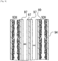
- Figs. 7 and 8 show a case in which metal particles 82 are introduced into the heating cells 93H such that the metal particles 82 are included in a coating layer 80 formed on the inner surface of the cell-wall 94 of the heating cell 93H.
- the ceramic base body 90 has a plurality of heating cells 93H in which a coating layer 80 including a plurality of metal particles 82 is formed on the inner surface of the cell-wall 94.
- the coating layer 80 is formed in the cells 93 selected in the two-dimensional array of cells 93 in the ceramic base body 90.
- the coating layer 80 includes a bonding material in which a plurality of metal particles or metal fragments 82 for induction heating are dispersed. Glass may be an example of such bonding material.
- Glass may preferably be a high-melting point glass.
- the melting point of the high-melting point glass may be within a range between 900 to 1100 °C.
- the coating layer 80 may be formed by introducing a slurry into the cells 93 of the ceramic base body 90 and the drying and thermally processing the slurry, not necessarily limited to this though.
- the slurry used here may include a plurality of metal particles or metal fragments 82, powder of bonding material (e.g. glass), and dispersion medium (e.g. water), for example. Viscosity of slurry may be set appropriately.
- a temperature of drying oven used to dry the slurry may be 120 °C, for example.
- a temperature of oven used for thermal processing of slurry may be 950 °C, for example. In some instances, the temperature of thermal processing may be equal to or greater than 5 times, 6 times, or 7 times of the temperature of drying.
- the temperature of thermal processing may be equal to or less than 8 times of the temperature of drying.
- the thermal processing of slurry for forming the coating layer 80 is performed under a non-oxidizing atmosphere, i.e. an atmosphere in which oxygen does not exist for preventing the oxidization of metal particles.
- a non-oxidizing atmosphere i.e. an atmosphere in which oxygen does not exist for preventing the oxidization of metal particles.
- the thermal processing temperature is 950 °C
- the thermal processing can be performed at a nitrogen atmosphere, for example.
- metal particles will be bonded due to bonding via glass powder.
- a temperature of 1100 °C for thermal processing can be employed.
- thermal processing may preferably be performed under a vacuum atmosphere.
- the above-described sealing portion 96 can be employed and/or a cover 71 described below can be employed.
- the sealing portion 96 seals the open end of the cell 93 at one or both of the first end 91 and the second end 92 of the ceramic base body 90.
- the sealing portion 96 is provided to block the slurry from flowing out of the cell 93 and/or to block a catalyst from flowing into the heating cell 93H.
- the sealing portion 96 can include the same material as described above. Similar to the case described above, an open end of selected cell 93 of the ceramic base body 90 may be sealed by a sealing material, and the ceramic base body 90 may be fired so that the sealing portion 96 will be obtained.
- Figs. 7 and 8 show that supplying and drying of the slurry is followed by a thermal processing at 900 to 1100 °C so that solid content of the slurry is bonded to the ceramic base body, and accordingly the coating layer 80 is formed on the inner surface of the cell-wall 94 of the ceramic base body 90.
- metal particles 82 are dispersed in a bonding material 81 such as glass.
- a hollow 83 exists in a cell 93 in which the coating layer 80 has been formed in a cross-sectional plane that is orthogonal to an extending direction of the ceramic base body 90 between the first end 91 and the second end 92 .
- the coating layer 80 is formed so as to form the hollow 83, thereby facilitating to reduce a thermal stress of the cell-wall 94.
- a ratio of an area of the hollow 83 to an area of the cell 93 in that cross-sectional plane is equal to or greater than 20 %, 30 %, 35 %, 40 %, 45 % or 50 %.
- thermal expansion coefficient of the bonding material 81 differs from thermal expansion coefficient of the cell-wall 94.
- Coefficient of thermal expansion of ceramic material of the ceramic base body may be equal to or less than 2 ⁇ 10 -6 /K.
- Coefficient of thermal expansion of the bonding material 81 may be 3 ⁇ 10 -6 /K to 6 ⁇ 10 -6 /K.
- thermal expansion coefficient of the bonding material 81 is equal to or less than 4 ⁇ 10 -6 /K and has a value closer to the thermal expansion coefficient of ceramic material of the ceramic base body 90.
- the metal particles or metal fragments 82 are dispersed in the coating layer 80 formed on the inner surface of the cell 93.
- the metal particles or metal fragments 82 are dispersed around the above-described hollow 83 in the coating layer 80 formed on the inner surface of the cell 93.
- Heat generated by metal particles or metal fragments 82 is transmitted to the cell-wall 94 via the bonding material 81.
- the internal space of the catalyst cells 93C will be heated.
- heat generated by each of the metal particles or metal fragments 82 will be efficiently transmitted to the surrounding cell-wall 94.
- Fig. 9 is a schematic view showing a state in which catalyst layers 97 have been introduced into cells 93 of the ceramic base body 90 other than the selected cells 93 into which metal particles or metal fragments 82 had been introduced.
- the catalyst layer 97 may be a ternary catalyst that supports platinum-based metal catalyst particles in fine pores of beta-alumina, and etc. Similar to above descriptions, wash-coating method, injection or pressure-applied pouring can be employed as a method of introducing a catalyst into the cells 93 of the ceramic base body 90.
- a ceramic base body 90 is manufactured (S1). As described above, a clay may be molded through extrusion, dried and then fired, so that a ceramic base body 90 is obtained. Next, first open ends of selected cells 93 of the ceramic base body 90 are sealed (S2). For example, the first open end of cell 93 is sealed by a sealing material of the same raw material as the ceramic base body 90, and then it is fired. Next, a multiplicity of metal particles is supplied into the selected cell 93 via unsealed second open ends of the selected cells 93 (S3).
- the second open ends of the cells 93 into which the multiplicity of metal particles has been introduced are sealed (S4).
- the second open end of the cell 93 is sealed by a sealing material of the same raw material as the ceramic base body 90, and then it is fired.
- the ceramic base body 90 is manufactured (S1). As described above, a clay may be molded through extrusion, dried and then fired, so that a ceramic base body 90 is obtained. Next, a slurry is introduced into selected cells 93 of the ceramic base body 90 (S2).
- covers 71 are placed on respective terminal surfaces of the ceramic base body 90.
- the ceramic base body 90 is sandwiched by the covers 71, and respective open ends of cells 93 of the ceramic base body 90 are closed by the cover 71.
- apertures 72 are selectively formed in the cover 71.
- the aperture 72 is formed at a position that corresponds to a selected cell 93 that will be a heating cell 93H and allows a slurry to flow into a cell 93.
- the slurry is introduced into a selected cell 93 via the aperture 72.
- the cover 71 may be a resin or plastic sheet having one surface on which an adhesive agent is coated.
- the slurry may flow into the selected cell 93 of the ceramic base body 90 via the aperture 72 formed in the cover 71 placed on the terminal surface of the ceramic base body 90.
- the aperture may be formed at a cover at the opposite side relative to a side at which the slurry is injected. By confirming that the slurry flows out via this opposite-side aperture, it would be possible to assume that sufficient amount of slurry has been injected into the cell 93. That is, supply of the slurry may be ended when the slurry flows out of the selected cell 93 via the aperture in the cover at the opposite side.
- Forming the apertures in the cover 71 may be done by using a laser device, but should not be limited to this.
- a porous body of the ceramic base body 90 may absorb dispersion medium, e.g. water, and a layer mainly consisting of solid content may be formed on the cell-wall 94 of the ceramic base body 90.
- the fluidity of the slurry may be low and could be said as zero. Drying this ceramic base body 90 allows that the solid content of the slurry is bonded to the cell-wall 94 of the ceramic base body 90 (S3).
- the cover 71 may be removed from the ceramic base body 90. The solid content of the slurry is bonded to the cell-wall 94, and thus the solid content of the slurry may not drop off the selected cell 93 even after the cover 71 is removed.
- an open end of the selected cell 93 of the ceramic base body 90 is sealed by a sealing material (S4).
- a sealing material for example, the first and/or second open end of the cell 93 is sealed by a sealing material of the raw material that is identical to the raw material of the ceramic base body 90.
- the ceramic base body 90 is thermally processed (S5).
- the ceramic base body 90 is thermally processed in vacuum.
- the bonding material (i.e. glass) in the slurry is fired and bonded to the cell-wall 94 of the ceramic base body 90 (See Fig. 15 ).
- optional sealing material may be bonded to the ceramic base body 90 through firing.
- a slurry is introduced into the selected cells 93 as illustrated in Figs. 16 to 18 .
- a clay is introduced into a selected cell 93 via the aperture 72 formed in the first cover 71 on the terminal surface of the ceramic base body 90.
- the clay may be pressed against the first cover 71 so that the clay is pressed into the selected cell 93 via the aperture 72 in the first cover 71.
- the ceramic base body 90 in which one open ends (i.e. first open ends) of selected cells 93 have been sealed by the clary is dried. Accordingly, the clay at one open end (i.e. first open ends) of the selected cell 93 will be hardened and bonded to the ceramic base body 90.
- a slurry is introduced into the selected cells 93 via the other open ends (i.e. second open ends) of selected cells 93 not being sealed by the sealing portion 96.
- the slurry may be introduced into the selected cell 93 via the aperture 72' in the second cover 71'.
- the slurry introduced here may include at least metal particles and dispersion medium, and may have optionally glass particles and dispersant. It may be preferred to decrease the concentration of solid content included in the slurry.
- the dispersion medium included in the slurry introduced into the selected cells 93 e.g. water may flow into neighboring cells 93 around the selected cell 93 via the porous cell-wall 94 and may flow out of the ceramic base body 90 via that neighboring cells 93.
- the solid content included in the slurry cannot pass through the porous cell-wall 94, and may be accumulated within the selected cell 93, i.e. the porous cell-wall 94 (See the schematic view of Fig. 18 ).
- the ceramic base body 90 obtained as such would be thermally processed, and the solid content is fired and bonded to the cell-wall 94.
- An embodiment is envisaged in which an open end of the selected cell 93 at the side at which the slurry was introduced is further sealed by a sealing portion.
- a cylindrical ceramic base body made of cordierite having a diameter of 82 mm and a length of 85 mm was manufactured.
- the thickness of the cell-wall was 100 ⁇ m, and the density of cells was 62 cell/cm 2 .
- covers were placed on the respective terminal surfaces of the ceramic base body so that it is sealed.
- a laser device was used to form apertures in respective covers. Holes were formed at positions corresponding to open ends of cells 93 that will be heating cells 93H.
- the apertures were formed in the cover at intervals of 5 cells in longitudinal and lateral directions at each terminal surface of the ceramic base body. That is, the apertures were formed at a ratio of 1 cell per 25 cells (5 ⁇ 5 cells).
- the apertures were formed in respective covers placed on respective terminal surfaces of the ceramic base body at the opposite positions with respect to the same cell.
- a slurry including ferritic stainless-steel particles (average particle diameter is 10 ⁇ m), silica-based glass particles (average diameter is 2 ⁇ m), a dispersant, and water was injected into the cells via the apertures.
- the injection of the slurry ended at a timing when the slurry flowed out via the aperture in the cover at the opposite side relative to a side at which the slurry was injected.
- the catalyst substrate was thereafter dried for an hour at 120 °C.
- the catalyst substrate was thermally processed for an hour in vacuum at 1100 °C. A coating layer having a thickness of 35 ⁇ m was obtained.
- the weight of the coating layer in the entire catalyst substrate was 6.8 gram.
- a coating layer having a thickness of 100 ⁇ m was obtained. The weight of the coating layer in the entire ceramic base body was 19.0 gram.
- Ferritic stainless steel particles having average particle diameter of 100 ⁇ m were used. Other conditions were the same as the working example 1. A coating layer having a thickness of 33 ⁇ m was obtained. The weight of the coating layer in the entire ceramic base body was 7.0 gram.
- a cylindrical ceramic base body made of cordierite having a diameter of 82 mm and a length of 85 mm was manufactured.
- the thickness of the cell-wall was 100 ⁇ m, and the density of cells was 62 cell/cm 2 .
- covers were placed on the respective terminal surfaces of the ceramic base body so that it is sealed.
- a laser device was used to form apertures in respective covers. Holes were formed at positions corresponding to open ends of cells 93 that will be heating cells 93H.
- the apertures were formed in the cover at intervals of 5 cells in longitudinal and lateral directions at each terminal surface of the ceramic base body 90.
- the apertures were formed at a ratio of 1 cell per 25 cells (5 ⁇ 5 cells).
- the apertures were formed in respective covers placed on respective terminal surfaces of the ceramic base body at the opposite positions with respect to the same cell.
- a sealing material was pressed into a cell at which the aperture is formed at one of the terminal surfaces, and then it is dried to form a sealing portion.
- a mixed power including ferritic stainless-steel particles (average particle diameter is 100 ⁇ m) and silica-based glass particles (average diameter is 2 ⁇ m) was injected into the cell via the aperture in the cover while being vibrated. After that, a sealing material was pressed into the aperture through which the power had been injected, and then it was dried so that the powder was blocked from spilling out.
- the cover was removed thereafter and, through thermal processing for an hour at 950 °C in nitrogen atmosphere, the stainless particles were bonded to the cell-wall of the ceramic base body via glass and the bonding material (i.e. glass) was bonded to the ceramic base body.
- the bonding material i.e. glass
- ferritic stainless-steel particles having average particle diameter of 100 ⁇ m were used.
- a cylindrical ceramic base body made of cordierite having a diameter of 82 mm and a length of 85 mm was manufactured.
- the thickness of the cell-wall was 100 ⁇ m, and the density of cells was 62 cell/cm 2 .
- the porosity of the cell-wall was 28 %, and the average diameter of narrow pores was 1 ⁇ m.
- covers were placed on the respective terminal surfaces of the catalyst substrate so that it is sealed.
- a laser device was used to form apertures in respective covers. Holes were formed at positions corresponding to open ends of cells 93 that will be heating cells 93H.
- the apertures were formed in the cover at intervals of 5 cells in longitudinal and lateral directions at each terminal surface of the ceramic base body 90.
- the apertures were formed at a ratio of 1 cell per 25 cells (5 ⁇ 5 cells).
- the apertures were formed in respective covers placed on respective terminal surfaces of the ceramic base body at the opposite positions with respect to the same cell.
- a clay including cordierite particles and colloidal silica was rubbed via the aperture in the cover at one end of the ceramic base body to reach 3 mm depth, and then it was dried at 200 °C to form the sealing portion, and the cover at that end was peeled off.
- a slurry was injected into the cells via the apertures in the cover at a terminal surface of ceramic substrate at which the apertures-provided-cover remained, and a step in which water is discharged from the opposite terminal surface continued until the volume of drain water reached 600 cc.
- the injecting speed of the slurry was 20 cc/sec, and the time period of injection of slurry was 30 seconds.
- the slurry included ferritic stainless-steel particles (average particle diameter is 10 ⁇ m), silica-based glass particles (average diameter is 2 ⁇ m), a dispersant, and water.
- the catalyst substrate was thereafter dried for an hour at 120 °C. Next, the catalyst substrate was thermally processed for an hour at 1100 °C. The weight of the fillings in the entire ceramic substrate was 37.0 kg.
- the metal particles were successfully introduced and fixed within the selected cells 93.
Abstract
Description
- The present disclosure is directed to a catalyst substrate, a method of manufacturing the same, and an exhaust gas purification apparatus.
-
US Patent Application Publication No.2017/0022868 Specification discloses a technique in which metal wires are inserted into selected cells in a substrate and the substrate is heated based on induction heating. - When the metal wires are inserted into the selected cells in the substrate, one may consider that a diameter of metal wire should be increased in order to reduce an influence of shaking when the substrate is built into a moving body such as a two-wheeled vehicle or four-wheeled vehicle. However, it would be not easy to suitably insert, into the selected cells, such metal wires with increased diameter.
- A catalyst substrate according to an aspect of the present disclosure may include: a ceramic base body including first and second ends, the second end being opposite to the first end, and the ceramic base body being provided with a plurality of cells each extending between the first and second ends; and a plurality of metal particles or metal fragments introduced into one or more internal spaces of one or more selected cells in the plurality of cells, wherein each of the plurality of metal particles or metal fragments has a size equal to or less than an opening width of the cell, and the plurality of metal particles or metal fragments is configured to generate heat in accordance with varying magnetic field.
- In some embodiments, the first end and/or the second end is provided with a plurality of sealing portions, each of the plurality of sealing portions being configured to seal an open end of the selected cell. The plurality of metal particles or metal fragments may be included in a multiplicity of metal particles or metal fragments that at least partially occupies the internal space of the cell.
- In some embodiments, the sealing portion may be configured to prevent a catalyst from flowing into the selected cell. The catalyst substrate may consist of cordierite, and the plurality of sealing portions may consist of cordierite. The selected cell may be occupied by the plurality of metal particles or metal fragments entirely between the first and second ends. The plurality of metal particles or metal fragments may be bonded to one another and to the ceramic base body via a bonding material in the internal space of the cell. A coating layer, where the metal particles or metal fragments are dispersed, is formed on an inner surface of a cell-wall of the selected cell.
- In some embodiments, the first end and/or the second end may be provided with one or more sealing portions, the sealing portion being configured to seal an open end of the selected cell. The sealing portion may include at least ceramic material.
- In some embodiments, a hollow may exist in at least one selected cell, in which the coating layer has been formed, in a cross-sectional plane orthogonal to an extending direction of the ceramic base body between the first and second ends, and a ratio of an area of the hollow to an area of the cell in the cross-sectional plane is equal to or greater than 20 %. A ratio of an area of the hollow to an area of the cell in the cross-sectional plane may be equal to or greater than 50 %.
- In some embodiments, the plurality of metal particles or metal fragments may include metal particles or metal fragments of ferritic stainless steel or austenitic stainless steel.
- In some embodiments, the metal particles or metal fragments each may have an average particle size equal to or less than 100 µm.
- In some embodiments, thermal expansion coefficient of ceramic material of the ceramic base body may be equal to or less than 2 x10 -6 /K.
- In some embodiments, initial permeability of metal material of the metal particle or metal fragment may be equal to or greater than 5 x10 -5 H/m.
- In some embodiments, the ceramic base body may include ceramic oxide material.
- In some embodiments, a thickness of the cell-wall may be equal to or less than 0.2 mm.
- An exhaust gas purification apparatus according to an aspect of the present disclosure may include: an exhaust gas purification device that comprises a catalyst substrate supporting a catalyst; and a coil wiring that spirally surrounds the exhaust gas purification device, the catalyst substrate comprising: a ceramic base body including first and second ends, the second end being opposite to the first end, and the ceramic base body being provided with a plurality of cells each extending between the first and second ends; and a plurality of metal particles or metal fragments introduced into one or more internal spaces of one or more selected cells in the plurality of cells of the ceramic base body, each of the metal particles or metal fragments having a size equal to or less than an opening width of the cell and generating heat in accordance with varying magnetic field, and the catalyst being introduced into one or more cells other than the selected cells.
- A method of manufacturing a catalyst substrate according to an aspect of the present disclosure may include:
- preparing a ceramic base body including first and second ends, the second end being opposite to the first end, and the ceramic base body being provided with a plurality of cells each extending between the first and second ends; and
- introducing a plurality of metal particles or metal fragments into one or more internal spaces of one or more selected cells in the plurality of cells of the ceramic base body, wherein
- each of the plurality of metal particles or metal fragments has a size equal to or less than an opening width of the cell, and
- the plurality of metal particles or metal fragments is configured to generate heat in accordance with varying magnetic field.
- In some embodiments, the method may further includes forming a plurality of sealing portions at the first end and/or the second end, each of the plurality of sealing portions being configured to seal an open end of the selected cell. Slurry including at least the plurality of metal particles or metal fragments, powder of bonding material, and dispersion medium may be introduced into the respective selected cells. When the slurry is introduced into the selected cell, the dispersion medium of the slurry may flow into one or more adjacent cells at least through a cell-wall of selected cell such that a solid content accumulates inside the selected cell.
- In some embodiments, said forming a plurality of sealing portions at the first end and/or the second end may include:
- introducing a clay into the selected cell through an aperture formed in a cover placed on a terminal surface of the ceramic base body; and
- drying the ceramic base body.
- In some embodiments, first and second covers may be placed onto respective terminal surfaces at the first and second ends, the slurry may be introduced into the selected cell through an aperture formed in the first cover, and the introducing of the slurry may end when the slurry flows out of the selected cell via an aperture formed in the second cover.
- In some embodiments, the internal space of the cell may be filled with powder at least including a multiplicity of metal particles or metal fragments.
- In some embodiments, the method may further include: sealing, by a sealing material, an open end of the cell into which the multiplicity of metal particles or metal fragments will be introduced. The sealing material may include at least ceramic material.
- In some embodiments, said forming a plurality of sealing portions at the first end and/or the second end may include:
- introducing a clay into the selected cell through an aperture formed in a cover placed on a terminal surface of the ceramic base body; and
- drying the ceramic base body.
- In some embodiments, the method of manufacturing a catalyst substrate may further include:
covering, by a cover, first or second terminal surface at the first or second end of the ceramic base body, the cover having an aperture that allows slurry to flow into the cell. The supplying of the slurry may end when the slurry flows out of the selected cell via a second aperture formed in a second cover arranged at the opposite side. - In some embodiments, the method of manufacturing a catalyst substrate may further include drying the ceramic base body in which the slurry has been introduced into the internal space of the selected cell so that a solid content of the slurry is bonded to the cell-wall extending around the cell.
- In some embodiments, the method of manufacturing a catalyst substrate may further include thermally processing the ceramic base body in a non-oxidizing atmosphere after the slurry has been dried.
- According to an aspect of the present disclosure, an alternative solution to the metal wires would be provided.
-
-
Fig. 1 is a schematic view of a channel for exhaust gas into which an exhaust gas purification apparatus according to an aspect of the present disclosure has been arranged. -
Fig. 2 is a schematic perspective view of a ceramic base body according to an aspect of the present disclosure, schematically illustrating a portion of cells within a dashed circle which are opened at a first end of the ceramic base body. -
Fig. 3 is an elevational schematic view of a first end of a ceramic base body of a catalyst substrate according to an aspect of the present disclosure in which selected cells are labelled with hatching. -
Fig. 4 is a schematic cross-sectional view taken along a line IV-IV inFig. 3 . -
Fig. 5 is a schematic cross-sectional view taken along a line V-V inFig. 4 . -
Fig. 6 is a schematic view showing a state in which catalyst has been introduced into cells of the ceramic base body illustrated inFig. 4 . -
Fig. 7 is a schematic cross-sectional view of a catalyst substrate according to another embodiment, corresponding to a section along a line IV-IV inFig. 3 . -
Fig. 8 is a schematic cross-sectional view taken along a line VIII-VIII inFig. 7 . -
Fig. 9 is a schematic view showing a state in which catalyst has been introduced into cells. -
Fig. 10 is a schematic flowchart showing a method of manufacturing a catalyst substrate. -
Fig. 11 is a schematic flowchart showing a method of manufacturing a catalyst substrate. -
Fig. 12 is a schematic view showing a state in which covers have been placed on respective terminal surfaces of a ceramic base body. -
Fig. 13 is a schematic view showing a state in which apertures have been selectively formed in the covers placed on the terminal ends of the ceramic base body. -
Fig. 14 is a schematic view showing a state in which a slurry is introduced into selected cells in the ceramic base body via apertures formed in the cover. -
Fig. 15 is a schematic view showing a state in which bonding material has been introduced into cells in the ceramic base body. -
Fig. 16 is a schematic view showing that clay is introduced into cells via apertures formed in a cover so that sealing portions are formed. -
Fig. 17 is a schematic view showing a state in which a cover has been removed. -
Fig. 18 is a schematic view showing a state in which slurry is introduced into selected cells via open ends of selected cells and its solid content is accumulated selectively within the selected cells. - Hereinafter, non-limiting exemplary embodiments of the present invention will be described with references to
Figs. 1 to 18 . A skilled person would be able to combine the respective embodiments and/or respective features without requiring excess descriptions. A skilled person would also be able to understand synergic effect by such combinations. Overlapping descriptions among exemplary embodiments will be basically omitted. Referenced drawings are mainly for the purpose of illustrating an invention and may possibly be simplified for the sake of convenience of illustration. The respective features identified by the language of "In some instances" in the present specification would be understood as an universal feature that is effective not only to a catalyst substrate and/or a method of manufacturing a catalyst substrate disclosed in the drawings for example, but also effective to other various catalyst substrates and/or methods of manufacturing a catalyst substrate. -
Fig. 1 is a schematic view of a channel for exhaust gas into which an exhaust gas purification apparatus has been arranged. A channel for exhaust gas is defined by ametal pipe 2. An exhaustgas purification apparatus 6 is provided at a radially-enlargedtube portion 2a of themetal pipe 2. The exhaustgas purification apparatus 6 has an exhaustgas purification device 3 in which a catalyst substrate supports a catalyst; acoil wiring 4 that helically extends around the outer circumference of the exhaustgas purification device 3; and a securingmember 5 that is used for securing the exhaustgas purification device 3 and thecoil wiring 4 inside of themetal pipe 2. A catalyst supported by the catalyst substrate of the exhaustgas purification device 3 may be a noble metal-based catalyst or any other types of catalysts, for example. The noble metal based catalysts may include a ternary catalyst or oxidized catalyst, which supports a noble metal such as platinum (Pt), palladium (Pd), and rhodium (Rh) by a surface of fine pore of alumina and includes ceria, zirconia and so on as a promoter, or a NOx occlusion reduction catalyst which includes alkaline earth metal and platinum as occlusive components of nitrogen oxide (NOx). A catalyst not using a noble metal may include a NOx selective reduction catalyst that includes a copper-substituted or iron-substituted zeolite and so on, for example. - In the present specification, "a catalyst substrate included in an exhaust gas purification device" will indicate that the catalyst substrate is actually supporting a catalyst. However, in the present specification, "a catalyst substrate" alone will indicate a catalyst substrate that is not supporting a catalyst yet unless it is expressly stated that "the catalyst substrate" is supporting a catalyst. As described below, a catalyst may be introduced into one or
more cells 93 of aceramic base body 90 other thancells 93 into which metal particles ormetal fragments 82 have been introduced. - The
coil wiring 4 is helically wound around the outer circumference of the exhaustgas purification device 3. Envisaged are embodiments where two ormore coil wirings 4 are used. In accordance with turning-ON of a switch SW, an alternating current supplied from an AC power source CS flows in thecoil wiring 4. A periodically changing magnetic field is in turn generated around thecoil wiring 4. Note that the ON/OFF of the switch SW may be controlled by acontroller 1. Thecontroller 1 is capable of turning ON the switch SW in synchronization with starting of an engine and is capable of allowing an alternating current to flow in thecoil wiring 4. Note that, an embodiment is envisaged where thecontroller 1 turns ON the switch SW independently of starting of an engine (for example, in accordance with activation of a heating switch pushed by a driver). The securingmember 5 may be a refractory member and may be provided to secure inside of themetal pipe 2 the exhaustgas purification device 3, supporting a catalyst, and thecoil wiring 4. - It has been considered that, when an engine starts, a temperature of exhaust gas reaching the exhaust
gas purification device 3 will likely be not sufficiently high. In this case, it is concerned that chemical reaction expected to be promoted by a catalyst supported by the catalyst substrate of the exhaustgas purification device 3 does not progress well, and harmful components in the exhaust gas, i.e. carbon monoxide (CO), nitrogen oxide (NOx), and hydrocarbon (CH) may pass through the exhaustgas purification device 3 as it is. In the present disclosure, the temperature of the exhaustgas purification device 3 will be increased in accordance with the changing magnetic field that is caused in accordance with the alternating current flowing thecoil wiring 4. This increase in the temperature of the exhaustgas purification device 3 will increase the temperature of the catalyst supported by the catalyst substrate included in the exhaustgas purification device 3, thus the catalyst reaction being facilitated. In particular, carbon monoxide (CO), nitrogen oxide (NOx), and hydrocarbon (CH) may be oxidized or reduced to be carbon dioxide (CO2), nitrogen (N2), and water (H2O). - The catalyst substrate that is expected to support a catalyst has a ceramic base body 90 (See
Figs. 2 and3 ), and a plurality of metal particles or metal fragments 82 (SeeFigs. 4 to 9 ) that is introduced into one or more internal spaces of one ormore cells 93 selected in a plurality ofcells 93 of theceramic base body 90. - The
ceramic base body 90 has afirst end 91 and asecond end 92 opposite to thefirst end 91. In particular, theceramic base body 90 is a columnar article having afirst end 91 and asecond end 92 opposite to thefirst end 91. Theceramic base body 90 could take various shapes such as a cylinder or a prism. Theceramic base body 90 is provided with the plurality ofcells 93 each extending between thefirst end 91 and thesecond end 92. Eachcell 93 is defined by a cell-wall 94 and has a first open end at thefirst end 91 side and a second open end at thesecond end 92 side. A fluid can communicate between thefirst end 91 and thesecond end 92 via thecell 93. The cell 93Could take various opening shapes. For example, its opening shape can be triangle, rectangle, pentagon, hexagon, octagon, circle, ellipse or any combination thereof. - One of the
first end 91 and thesecond end 92 is arranged at an upstream side in the channel for exhaust gas, and the other one of thefirst end 91 and thesecond end 92 is arranged at a downstream side in the channel for exhaust gas. Thus, it can be alternatively referred to as an upstream or downstream end. Note that, theceramic base body 90 is provided with an outercircumferential wall 95 that is thicker than the cell-wall 94. - The
ceramic base body 90 may be a non-conductive porous body, for example. Theceramic base body 90 may include an oxide-based ceramic material. The oxide-based ceramic material may be one or more material selected from a group consisting of alumina (Al2O3), zirconia (ZrO2), magnesia (MgO), titania (TiO2), silica (SiO2), and aluminum titanate. In a case, theceramic base body 90 includes cordierite (2MgO • 2Al2O3 • 5SiO2) or is made of cordierite (2MgO • 2Al2O3 • 5SiO2). - A method of manufacturing a
ceramic base body 90 that is made of cordierite (2MgO • 2Al2O3 • 5SiO2) is well established in the art. Firstly, a clay is molded through extrusion, and a soft molded body obtained by the extrusion molding is dried and fired. The clay may include at least a raw material that will be cordierite (2MgO • 2Al2O3 • 5SiO2) by firing, an organic binder, and dispersion medium (carrier fluid). In a step of firing, the binder included in the clay will be removed, and porousceramic base body 90 will be obtained. - The raw material that will be cordierite (2MgO • 2AbO3 • 5SiO2) by firing may be referred to as a raw material for cordierite. The raw material for cordierite may have a chemical composition in which silica is within 40 to 60 mass%, alumina is 15 to 45 mass%, and magnesia is within 5 to 30 mass%. The raw material for cordierite may be a mixture of a plurality of inorganic material selected from a group consisting of talc, kaolin, calcined kaolin, alumina, aluminum hydroxide, and silica. The organic binder may include at least one material selected from a group consisting of agar, hydroxypropyl methylcellulose, methylcellulose, hydroxyl ethylcellulose, carboxy methylcellulose, and polyvinyl alcohol. The firing temperature may be set within 1380 to 1450 °C or 1400 to 1440 °C. The firing time period may be within 3 to 10 hours.
- If required, a pore-forming agent may be added to the clay. The pore-forming agent may be any material that will disappear during a step of firing, and may include, for example, inorganic material such as coke, a highly polymerized compound such as foamed plastic (foamed resin), organic material such as a starch or any combination thereof. The dispersion medium may include ethylene glycol, dextrin, fatty acid soap, polyalcohol or any combination thereof, additionally or alternative to water.
- In the present embodiment, the metal particles or
metal fragments 82 are introduced into one or more internal spaces of one ormore cells 93 selected in the plurality ofcells 93 of theceramic base body 90. Each metal particle ormetal fragment 82 has a size equal to or less than an opening width W93 of thecell 93, and generates heat in accordance with varying magnetic field. An introducing ratio or introducing manner of metal particles ormetal fragments 82 will be preferably determined so as to reduce an influence of shaking when the catalyst substrate is built into a moving body such as a two-wheeled vehicle or four-wheeled vehicle, or so as to enhance efficiency of manufacturing of a catalyst substrate. The opening width W93 of thecell 93 may be equal to a minimum width of thecell 93 in a cross-sectional plane that is orthogonal to an extending direction of theceramic base body 90 between thefirst end 91 and thesecond end 92. - The plurality of metal particles or
metal fragments 82 having been introduced into one or more internal spaces of one ormore cells 93 selected in the plurality ofcells 93 of theceramic base body 90 is used for induction heating and not used for catalyst reaction. Hereinafter, these one ormore cells 93 into which metal particles ormetal fragments 82 have been introduced for induction heating will be referred to as "heating cell(s)".Cells 93 other than the "heating cells" are cells into which a catalyst will be introduced in future, and will be referred to as "catalyst cell(s)". - The metal particles or
metal fragments 82 for induction heating which are introduced into the selectedcells 93 of theceramic base body 90 may include metal particles ormetal fragments 82 of stainless steel such as metal particles ormetal fragments 82 of ferritic stainless steel. Additionally or alternatively, the metal particles ormetal fragments 82 for induction heating may include martensitic stainless steel, austenitic stainless steel, invar or super invar. The metal particles ormetal fragments 82 for induction heating may present a magnetic property. In some instances, initial permeability of metal material of metal particles ormetal fragments 82 is equal to or greater than 5 × 10⁻⁵ H/m. - The
ceramic base body 90 has M (M is an integer equal to or greater than 2)catalyst cells 93C and N (N is an integer equal to or greater than 2, and is less than M)heating cells 93H (SeeFig. 3 ). The number ofheating cells 93H is less than the number ofcatalyst cells 93C. In this case, an ability of the exhaustgas purification apparatus 6 for purifying the exhaust gas would be prevented from being lowered together with the introduction of theheating cells 93H. - The
heating cells 93H are regularly arranged in the two dimensional array of cells 93 (SeeFig. 3 ). In some instances, theheating cells 93H are arranged at intervals of Q (Q is an integer equal to or greater than 2) rows and P (P is an integer equal to or greater than 2) columns in the two-dimensional array ofcells 93. In a case illustrated inFig. 3 , theheating cells 93H are regularly arranged at intervals of 2 rows and 2 columns. In a case as such where oneheating cell 93H is surrounded byplural catalyst cells 93C, theplural catalyst cells 93C can receive heat transmitted from thecommon heating cell 93H, and thus a deviation may not be caused in a temperature distribution in theceramic base body 90. In some instances, theheating cells 93H are arranged at intervals of 5 cells, but not necessarily limited to this though. - Alternating current of 30 Hz or greater, 100 Hz or greater, or 200 Hz or greater may flow in the
coil wiring 4. When the alternating current flows in thecoil wiring 4, eddy current will flow in each of the metal particles ormetal fragments 82 introduced into thecell 93 of theceramic base body 90, and in turn joule heat will be generated. In accordance with increase in frequency of alternating current flowing in thecoil wiring 4, more current will likely flow nearby a surface of metal particle ormetal fragment 82, and more heat will be generated nearby the surface of metal particle ormetal fragment 82. This is a result of "Skin Effect". That is, compared with a case of metal wires, metal particles ormetal fragments 82 would allow that greater heat will be obtained by lesser amount of metals (in other words, lesser amount of increased weight). The metal particle ormetal fragment 82 may have an average particle size equal to or less than 100 µm, 80 µm, 60 µm, 50 µm, 40 µm, 30 µm, or 20 µm, not necessarily limited to this though. - As illustrated in
Fig. 4 , themetal particles 82 introduced into thecell 93 are included in a multiplicity of metal particles which at least partially occupies the internal space of thecell 93. In other words, theceramic base body 90 has a plurality of cells 93 (i.e.heating cells 93H) at least partially occupied by a multiplicity of metal particles. The multiplicity of metal particles is introduced into thecells 93 selected in the two-dimensional array ofcells 93 in theceramic base body 90. Note that, in a case in which a diameter of each metal particle in the multiplicity of metal particles is small, it would be understood that a powder made of the multiplicity of metal particles is introduced into thecell 93. - In order to block a catalyst from entering at the time of coating of catalyst, a sealing
portion 96 that seals an open end of thecell 93 may be provided at one or both of thefirst end 91 and thesecond end 92 of theceramic base body 90. Even when a catalyst was introduced into aheating cell 93H, the catalyst might be deteriorated due to heating by the metal particles. Thus, it would be not appropriate to expect that functionality of catalyst will be sustained over a long period of time. By using the sealingportion 96, this loss of catalyst may be suppressed or avoided. The sealingportion 96 may also prevent the metal particles inside of theheating cell 93H from being oxidized and deteriorated due to contact between the metal particle inside of theheating cell 93H and an exhaust gas. - The sealing
portion 96 can include at least ceramic material. The sealingportion 96 can include other material such as glass additionally to the ceramic material. For example, theceramic base body 90 and the sealingportion 96 include cordierite (2MgO • 2Al2O3 • 5SiO2). Combination of cordierite-madeceramic base body 90 and cordierite-made sealingportion 96 would reduce a difference in thermal expansion that may otherwise be caused between them. That is, in some instances, theceramic base body 90 and the sealingportion 96 include identical ceramic material. Note that, the sealingportion 96 can be a porous body likewise theceramic base body 90. - The sealing
portion 96 may be obtained by sealing an open end of selectedcell 93 of theceramic base body 90 using a sealing material, and then calcining theceramic base body 90 at a temperature equal to or less than 950 °C, not necessarily limited to this though. That is, the sealing material is bonded to theceramic base body 90 through a step of calcination so that the sealingportion 96 is formed. The sealing material may include at least ceramic material in some instances. For example, the sealing material is made of a mixture including cordierite particles and colloidal silica, and the sealing material will be bonded to theceramic base body 90 by the colloidal silica through calcination, but not necessarily limited to this though. - The metal particles or metal fragments are introduced into the
cell 93 of theceramic base body 90 via an open end of thecell 93. An embodiment is envisaged in which bonding material (e.g. glass powder (glass particles)) is additionally introduced into thecell 93 of theceramic base body 90 via the open end of thecell 93. After the metal particles or metal fragments have been introduced into thecell 93, the bonding material would be melted by heating theceramic base body 90. As a result, bonding of metal particles via the bonding material inside of thecell 93 is caused, and also bonding of metal particle with theceramic base body 90 is caused. In a preferred embodiment, powder mixture of at least a multiplicity of metal particles and glass powder is introduced into thecell 93. - A method of introducing into the cell 93 a powder mixture including a multiplicity of metal particles or including a multiplicity of metal particles and glass powder may include a method in which the
ceramic base body 90 is vibrated at several Hz to 1k Hz and the powder is allowed to be introduced into the cell due to the gravity. As an alternative method, one open end ofcell 93 is sealed by a sealing portion, and a slurry is fed into thecell 93 through the open end of thecell 93. The slurry may be a fluid in which a solid content such as metal particles and glass powder are dispersed in dispersion medium (carrier liquid) such as water. In order to ensure fluidity of the slurry, concentration of solid content in the slurry may be set to be low. Note that, it is envisaged that the slurry flows into thecell 93 based on suction. In this method, a solvent e.g. water may be discharged from an end of theceramic base body 90 that is opposite to an end at which the slurry is introduced. Solvent component of the slurry can pass through the porous cell-wall 94, but the solid content of the slurry cannot pass through the cell-wall 94 and will be accumulated within the selectedcell 93, i.e. onto the cell-wall 94 surrounding/defining the selectedcell 93. -
Figs. 4 and5 illustrate that the internal space of thecell 93 is fully occupied by metal particles, but should not be limited to this manner. A case is envisaged in which a multiplicity of metal particles can flow in the internal space of thecell 93, except bonding material was introduced into thecell 93 and metal particles or metal fragments were bonded via the bonding material, e.g. glass material. Furthermore,Figs. 4 and5 illustrate spherical metal particles, but the shape of metal particle should not be limited to a sphere. It is envisaged that metal fragments are used additionally to or alternative to metal particles. The metal fragments could have any shape in so far as it has a size equal to or less than the opening width W93 of thecell 93. An embodiment is envisaged in which different size and shapes of metal particles or fragments are introduced into a common selectedcell 93. -
Fig. 6 is a schematic view showing a state in which acatalyst layer 97 has been introduced into thecatalyst cells 93C of theceramic base body 90 illustrated inFig. 4 . Wash-coating method has been known as a way to introduce a catalyst into theceramic base body 90. In wash-coating method, a slurry including catalyst is supplied into the cells of the catalyst substrate. Note that, supplying a slurry into the cells of the catalyst substrate could be performed by immersing a catalyst substrate into a solution of slurry. Solvent component of the slurry will be absorbed by the porous cell-wall 94, thus facilitating settlement of thecatalyst layer 97 onto the cell-wall 94. It should be noted that other methods than the wash-coating method such as injection or pressure-applied pouring can be adopted. - The cell-
wall 94 of thecatalyst cell 93C has an inner surface for supporting a catalyst. In contrast, the cell-wall 94 of theheating cell 93H has an inner surface for confining metal particles orfragments 82 inside of theheating cell 93H. It should be noted thatFig. 6 schematically illustrates a state in which thecatalyst layer 97 is coated onto the inner surface of the cell-wall 94 of theheating cell 93H. Thecatalyst layer 97 is introduced into thecell 93 such that thecatalyst layer 97 is formed across thefirst end 91 and thesecond end 92 of theceramic base body 90. For example, thecatalyst layer 97 includes a catalyst base member and a multiple of catalyst particles attached to the catalyst base member, but should not be limited to this. - The thickness of the cell-
wall 94 may be equal to or less than 0.2 mm, not necessarily limited to this though. Thinning of cell-wall 94 would reduce thermal capacity of cell-wall. Reduction of thermal capacity of the cell-wall 94 would facilitate increase in temperature of catalyst supported by the cell-wall 94 or increase in temperature of exhaust gas. As a result, harmful components in exhaust gas are suppressed to pass through the exhaustgas purification apparatus 6 as it is. -
Figs. 7 and8 show a case in whichmetal particles 82 are introduced into theheating cells 93H such that themetal particles 82 are included in acoating layer 80 formed on the inner surface of the cell-wall 94 of theheating cell 93H. Theceramic base body 90 has a plurality ofheating cells 93H in which acoating layer 80 including a plurality ofmetal particles 82 is formed on the inner surface of the cell-wall 94. Thecoating layer 80 is formed in thecells 93 selected in the two-dimensional array ofcells 93 in theceramic base body 90. In some instances, thecoating layer 80 includes a bonding material in which a plurality of metal particles ormetal fragments 82 for induction heating are dispersed. Glass may be an example of such bonding material. Glass may preferably be a high-melting point glass. The melting point of the high-melting point glass may be within a range between 900 to 1100 °C. By using a high-melting point glass, heat-resistance ofheating cells 93H would be improved. - The
coating layer 80 may be formed by introducing a slurry into thecells 93 of theceramic base body 90 and the drying and thermally processing the slurry, not necessarily limited to this though. The slurry used here may include a plurality of metal particles ormetal fragments 82, powder of bonding material (e.g. glass), and dispersion medium (e.g. water), for example. Viscosity of slurry may be set appropriately. A temperature of drying oven used to dry the slurry may be 120 °C, for example. A temperature of oven used for thermal processing of slurry may be 950 °C, for example. In some instances, the temperature of thermal processing may be equal to or greater than 5 times, 6 times, or 7 times of the temperature of drying. The temperature of thermal processing may be equal to or less than 8 times of the temperature of drying. - It may be preferable that the thermal processing of slurry for forming the
coating layer 80 is performed under a non-oxidizing atmosphere, i.e. an atmosphere in which oxygen does not exist for preventing the oxidization of metal particles. In a case where the thermal processing temperature is 950 °C, the thermal processing can be performed at a nitrogen atmosphere, for example. In a case where the thermal processing temperature is 950 °C, metal particles will be bonded due to bonding via glass powder. As a higher temperature for thermal processing, a temperature of 1100 °C for thermal processing can be employed. In this instance, thermal processing may preferably be performed under a vacuum atmosphere. By the thermal processing at 1100 °C, metal particles will be bonded one another. Accordingly, it would be possible to control a size of conductive unit, i.e. a bonded body of metal particles. - In order to block the slurry from flowing out of the
cell 93, the above-describedsealing portion 96 can be employed and/or acover 71 described below can be employed. In a case where the sealingportion 96 is employed, the sealingportion 96 seals the open end of thecell 93 at one or both of thefirst end 91 and thesecond end 92 of theceramic base body 90. The sealingportion 96 is provided to block the slurry from flowing out of thecell 93 and/or to block a catalyst from flowing into theheating cell 93H. The sealingportion 96 can include the same material as described above. Similar to the case described above, an open end of selectedcell 93 of theceramic base body 90 may be sealed by a sealing material, and theceramic base body 90 may be fired so that the sealingportion 96 will be obtained. -
Figs. 7 and8 show that supplying and drying of the slurry is followed by a thermal processing at 900 to 1100 °C so that solid content of the slurry is bonded to the ceramic base body, and accordingly thecoating layer 80 is formed on the inner surface of the cell-wall 94 of theceramic base body 90. In thecoating layer 80,metal particles 82 are dispersed in abonding material 81 such as glass. As would be understood fromFig. 8 , a hollow 83 exists in acell 93 in which thecoating layer 80 has been formed in a cross-sectional plane that is orthogonal to an extending direction of theceramic base body 90 between thefirst end 91 and thesecond end 92 . Thecoating layer 80 is formed so as to form the hollow 83, thereby facilitating to reduce a thermal stress of the cell-wall 94. In some instances, a ratio of an area of the hollow 83 to an area of thecell 93 in that cross-sectional plane is equal to or greater than 20 %, 30 %, 35 %, 40 %, 45 % or 50 %. Note that, thermal expansion coefficient of thebonding material 81 differs from thermal expansion coefficient of the cell-wall 94. Coefficient of thermal expansion of ceramic material of the ceramic base body may be equal to or less than 2×10⁻⁶/K. Coefficient of thermal expansion of thebonding material 81 may be 3×10⁻⁶ /K to 6×10⁻⁶ /K. In a preferred instance, thermal expansion coefficient of thebonding material 81 is equal to or less than 4×10⁻⁶ /K and has a value closer to the thermal expansion coefficient of ceramic material of theceramic base body 90. - As illustrated in
Figs. 7 and8 , the metal particles ormetal fragments 82 are dispersed in thecoating layer 80 formed on the inner surface of thecell 93. The metal particles ormetal fragments 82 are dispersed around the above-described hollow 83 in thecoating layer 80 formed on the inner surface of thecell 93. Heat generated by metal particles ormetal fragments 82 is transmitted to the cell-wall 94 via thebonding material 81. Along with increase in temperature of the cell-wall 94, the internal space of thecatalyst cells 93C will be heated. As the metal particles ormetal fragments 82 exist around the hollow 83, heat generated by each of the metal particles ormetal fragments 82 will be efficiently transmitted to the surrounding cell-wall 94. -
Fig. 9 is a schematic view showing a state in which catalyst layers 97 have been introduced intocells 93 of theceramic base body 90 other than the selectedcells 93 into which metal particles ormetal fragments 82 had been introduced. Thecatalyst layer 97 may be a ternary catalyst that supports platinum-based metal catalyst particles in fine pores of beta-alumina, and etc. Similar to above descriptions, wash-coating method, injection or pressure-applied pouring can be employed as a method of introducing a catalyst into thecells 93 of theceramic base body 90. - Description will be made for a non-limiting method of manufacturing a catalyst substrate with reference to
Figs. 10 and11 . In an instance shown inFig. 10 , firstly, aceramic base body 90 is manufactured (S1). As described above, a clay may be molded through extrusion, dried and then fired, so that aceramic base body 90 is obtained. Next, first open ends of selectedcells 93 of theceramic base body 90 are sealed (S2). For example, the first open end ofcell 93 is sealed by a sealing material of the same raw material as theceramic base body 90, and then it is fired. Next, a multiplicity of metal particles is supplied into the selectedcell 93 via unsealed second open ends of the selected cells 93 (S3). Next, the second open ends of thecells 93 into which the multiplicity of metal particles has been introduced are sealed (S4). For example, the second open end of thecell 93 is sealed by a sealing material of the same raw material as theceramic base body 90, and then it is fired. - In an instance shown in
Fig. 11 , firstly, theceramic base body 90 is manufactured (S1). As described above, a clay may be molded through extrusion, dried and then fired, so that aceramic base body 90 is obtained. Next, a slurry is introduced into selectedcells 93 of the ceramic base body 90 (S2). - As illustrated in
Fig. 12 , covers 71 are placed on respective terminal surfaces of theceramic base body 90. Theceramic base body 90 is sandwiched by thecovers 71, and respective open ends ofcells 93 of theceramic base body 90 are closed by thecover 71. Next, as illustrated inFig. 13 ,apertures 72 are selectively formed in thecover 71. Theaperture 72 is formed at a position that corresponds to a selectedcell 93 that will be aheating cell 93H and allows a slurry to flow into acell 93. The slurry is introduced into a selectedcell 93 via theaperture 72. Thecover 71 may be a resin or plastic sheet having one surface on which an adhesive agent is coated. - As illustrated in
Fig. 14 , the slurry may flow into the selectedcell 93 of theceramic base body 90 via theaperture 72 formed in thecover 71 placed on the terminal surface of theceramic base body 90. In some instances, in order to confirm that sufficient amount of slurry has been injected into thecell 93, the aperture may be formed at a cover at the opposite side relative to a side at which the slurry is injected. By confirming that the slurry flows out via this opposite-side aperture, it would be possible to assume that sufficient amount of slurry has been injected into thecell 93. That is, supply of the slurry may be ended when the slurry flows out of the selectedcell 93 via the aperture in the cover at the opposite side. Forming the apertures in thecover 71 may be done by using a laser device, but should not be limited to this. - In some instances, in the
ceramic base body 90 in which the slurry has been introduced into the selectedcells 93, a porous body of theceramic base body 90 may absorb dispersion medium, e.g. water, and a layer mainly consisting of solid content may be formed on the cell-wall 94 of theceramic base body 90. The fluidity of the slurry may be low and could be said as zero. Drying thisceramic base body 90 allows that the solid content of the slurry is bonded to the cell-wall 94 of the ceramic base body 90 (S3). In or after the step of drying, thecover 71 may be removed from theceramic base body 90. The solid content of the slurry is bonded to the cell-wall 94, and thus the solid content of the slurry may not drop off the selectedcell 93 even after thecover 71 is removed. - Next, optionally, an open end of the selected
cell 93 of theceramic base body 90 is sealed by a sealing material (S4). For example, the first and/or second open end of thecell 93 is sealed by a sealing material of the raw material that is identical to the raw material of theceramic base body 90. - Next, after fluidity of the slurry is lowered, the
ceramic base body 90 is thermally processed (S5). For example, theceramic base body 90 is thermally processed in vacuum. Accordingly, the bonding material (i.e. glass) in the slurry is fired and bonded to the cell-wall 94 of the ceramic base body 90 (SeeFig. 15 ). Also, optional sealing material may be bonded to theceramic base body 90 through firing. - It is also envisaged that a slurry is introduced into the selected
cells 93 as illustrated inFigs. 16 to 18 . Firstly, similar to above, a clay is introduced into a selectedcell 93 via theaperture 72 formed in thefirst cover 71 on the terminal surface of theceramic base body 90. The clay may be pressed against thefirst cover 71 so that the clay is pressed into the selectedcell 93 via theaperture 72 in thefirst cover 71. Next, theceramic base body 90 in which one open ends (i.e. first open ends) of selectedcells 93 have been sealed by the clary is dried. Accordingly, the clay at one open end (i.e. first open ends) of the selectedcell 93 will be hardened and bonded to theceramic base body 90. - Next, as illustrated in
Fig. 17 , the first cover at the side the sealingportions 96 have been formed is removed. Next, as illustrated inFig. 18 , a slurry is introduced into the selectedcells 93 via the other open ends (i.e. second open ends) of selectedcells 93 not being sealed by the sealingportion 96. Specifically, the slurry may be introduced into the selectedcell 93 via the aperture 72' in the second cover 71'. The slurry introduced here may include at least metal particles and dispersion medium, and may have optionally glass particles and dispersant. It may be preferred to decrease the concentration of solid content included in the slurry. - The dispersion medium included in the slurry introduced into the selected
cells 93, e.g. water may flow into neighboringcells 93 around the selectedcell 93 via the porous cell-wall 94 and may flow out of theceramic base body 90 via that neighboringcells 93. On the other hand, the solid content included in the slurry cannot pass through the porous cell-wall 94, and may be accumulated within the selectedcell 93, i.e. the porous cell-wall 94 (See the schematic view ofFig. 18 ). Theceramic base body 90 obtained as such would be thermally processed, and the solid content is fired and bonded to the cell-wall 94. An embodiment is envisaged in which an open end of the selectedcell 93 at the side at which the slurry was introduced is further sealed by a sealing portion. - A cylindrical ceramic base body made of cordierite having a diameter of 82 mm and a length of 85 mm was manufactured. The thickness of the cell-wall was 100 µm, and the density of cells was 62 cell/cm2. Next, covers were placed on the respective terminal surfaces of the ceramic base body so that it is sealed. Next, a laser device was used to form apertures in respective covers. Holes were formed at positions corresponding to open ends of
cells 93 that will be heatingcells 93H. The apertures were formed in the cover at intervals of 5 cells in longitudinal and lateral directions at each terminal surface of the ceramic base body. That is, the apertures were formed at a ratio of 1 cell per 25 cells (5∗5 cells). The apertures were formed in respective covers placed on respective terminal surfaces of the ceramic base body at the opposite positions with respect to the same cell. Next, a slurry including ferritic stainless-steel particles (average particle diameter is 10 µm), silica-based glass particles (average diameter is 2 µm), a dispersant, and water was injected into the cells via the apertures. The slurry had a weight ratio of ferritic stainless-steel particles/silica-based glass particles/dispersant/water = 66/33/1/140. The injection of the slurry ended at a timing when the slurry flowed out via the aperture in the cover at the opposite side relative to a side at which the slurry was injected. The catalyst substrate was thereafter dried for an hour at 120 °C. Next, the catalyst substrate was thermally processed for an hour in vacuum at 1100 °C. A coating layer having a thickness of 35 µm was obtained. The weight of the coating layer in the entire catalyst substrate was 6.8 gram. - A slurry having a weight ratio of ferritic stainless steel particles/silica-based glass particles/dispersant/water = 66/33/1/35 was used. Other conditions were the same as the working example 1. A coating layer having a thickness of 100 µm was obtained. The weight of the coating layer in the entire ceramic base body was 19.0 gram.
- Ferritic stainless steel particles having average particle diameter of 100 µm were used. Other conditions were the same as the working example 1. A coating layer having a thickness of 33 µm was obtained. The weight of the coating layer in the entire ceramic base body was 7.0 gram.
- Ferritic stainless steel particles having average particle diameter of 100 µm were used. Also, a slurry having a weight ratio of ferritic stainless-steel particles/silica-based glass particles/dispersant/water = 66/33/1/400 was used. Other conditions were the same as the working example 1. A coating layer having a thickness of 94 µm was obtained. The weight of the coating layer in the entire ceramic base body was 17.5 gram.
- A cylindrical ceramic base body made of cordierite having a diameter of 82 mm and a length of 85 mm was manufactured. The thickness of the cell-wall was 100 µm, and the density of cells was 62 cell/cm2. Next, covers were placed on the respective terminal surfaces of the ceramic base body so that it is sealed. Next, a laser device was used to form apertures in respective covers. Holes were formed at positions corresponding to open ends of
cells 93 that will be heatingcells 93H. The apertures were formed in the cover at intervals of 5 cells in longitudinal and lateral directions at each terminal surface of theceramic base body 90. The apertures were formed at a ratio of 1 cell per 25 cells (5∗5 cells). The apertures were formed in respective covers placed on respective terminal surfaces of the ceramic base body at the opposite positions with respect to the same cell. Next, a sealing material was pressed into a cell at which the aperture is formed at one of the terminal surfaces, and then it is dried to form a sealing portion. From the opposite terminal surface, a mixed power including ferritic stainless-steel particles (average particle diameter is 100 µm) and silica-based glass particles (average diameter is 2 µm) was injected into the cell via the aperture in the cover while being vibrated. After that, a sealing material was pressed into the aperture through which the power had been injected, and then it was dried so that the powder was blocked from spilling out. The cover was removed thereafter and, through thermal processing for an hour at 950 °C in nitrogen atmosphere, the stainless particles were bonded to the cell-wall of the ceramic base body via glass and the bonding material (i.e. glass) was bonded to the ceramic base body. In this example, ferritic stainless-steel particles having average particle diameter of 100 µm were used. Also, the mixed power used had a weight ratio of ferritic stainless-steel particles/silica-based glass particles = 90/10. The weight of the mixed power was 40.0 gram. - A cylindrical ceramic base body made of cordierite having a diameter of 82 mm and a length of 85 mm was manufactured. The thickness of the cell-wall was 100 µm, and the density of cells was 62 cell/cm2. The porosity of the cell-wall was 28 %, and the average diameter of narrow pores was 1 µm. Next, covers were placed on the respective terminal surfaces of the catalyst substrate so that it is sealed. Next, a laser device was used to form apertures in respective covers. Holes were formed at positions corresponding to open ends of
cells 93 that will be heatingcells 93H. The apertures were formed in the cover at intervals of 5 cells in longitudinal and lateral directions at each terminal surface of theceramic base body 90. That is, the apertures were formed at a ratio of 1 cell per 25 cells (5∗5 cells). The apertures were formed in respective covers placed on respective terminal surfaces of the ceramic base body at the opposite positions with respect to the same cell. Next, a clay including cordierite particles and colloidal silica was rubbed via the aperture in the cover at one end of the ceramic base body to reach 3 mm depth, and then it was dried at 200 °C to form the sealing portion, and the cover at that end was peeled off. Then, a slurry was injected into the cells via the apertures in the cover at a terminal surface of ceramic substrate at which the apertures-provided-cover remained, and a step in which water is discharged from the opposite terminal surface continued until the volume of drain water reached 600 cc. The injecting speed of the slurry was 20 cc/sec, and the time period of injection of slurry was 30 seconds. The slurry included ferritic stainless-steel particles (average particle diameter is 10 µm), silica-based glass particles (average diameter is 2 µm), a dispersant, and water. The weight ratio was as follows, ferritic stainless steel particles/silica-based glass particles/dispersant/water = 66/33/1/1000. The catalyst substrate was thereafter dried for an hour at 120 °C. Next, the catalyst substrate was thermally processed for an hour at 1100 °C. The weight of the fillings in the entire ceramic substrate was 37.0 kg. - In every working example, the metal particles were successfully introduced and fixed within the selected
cells 93. - Given the above teachings, a skilled person in the art would be able to add various modifications to the respective embodiments.
Claims (15)
- A catalyst substrate comprising:a ceramic base body (90) including first and second ends (91, 92), the second end (92) being opposite to the first end (91), and the ceramic base body (90) being provided with a plurality of cells (93) each extending between the first and second ends (91, 92); anda plurality of metal particles or metal fragments (82) introduced into one or more internal spaces of one or more selected cells (93H) in the plurality of cells (93), whereineach of the plurality of metal particles or metal fragments (82) has a size equal to or less than an opening width of the cell, andthe plurality of metal particles or metal fragments (82) is configured to generate heat in accordance with varying magnetic field.
- The catalyst substrate of Claim 1, wherein the first end (91) and/or the second end (92) is provided with a plurality of sealing portions, each of the plurality of sealing portions being configured to seal an open end of the selected cell (93H).
- The catalyst substrate of Claim 2, wherein the sealing portion is configured to prevent a catalyst from flowing into the selected cell (93H).
- The catalyst substrate of Claim 2 or 3, wherein the catalyst substrate consists of cordierite, and the plurality of sealing portions consist of cordierite.
- The catalyst substrate any one of Claims 2-4, wherein the selected cell (93H) is occupied by the plurality of metal particles or metal fragments (82) entirely between the first and second ends (91, 92)
and/or wherein the plurality of metal particles or metal fragments (82) are bonded to one another and to the ceramic base body (90) via a bonding material in the internal space of the cell. - The catalyst substrate any one of Claims 2-4, wherein a coating layer, where the metal particles or metal fragments (82) are dispersed, is formed on an inner surface of a cell-wall of the selected cell (93H).
- The catalyst substrate of Claim 6, wherein a hollow exists in at least one selected cell (93H), in which the coating layer has been formed, in a cross-sectional plane orthogonal to an extending direction of the ceramic base body (90) between the first and second ends (91, 92), and a ratio of an area of the hollow to an area of the cell in the cross-sectional plane is equal to or greater than 20 %.
- The catalyst substrate of Claim 7, wherein a ratio of an area of the hollow to an area of the cell in the cross-sectional plane is equal to or greater than 50 %.
- The catalyst substrate of any one of Claims 1-8, wherein the metal particles or metal fragments (82) each has an average particle size equal to or less than 100 µm,
and/or wherein a thermal expansion coefficient of ceramic material of the ceramic base body (90) is equal to or less than 2x10⁻⁶/K, and/or wherein an initial permeability of metal material of the metal particle or metal fragment is equal to or greater than 5x10⁻⁵H/m, and/or wherein a thickness of the cell-wall is equal to or less than 0.2 mm. - An exhaust gas purification apparatus, comprising:an exhaust gas purification device that comprises a catalyst substrate of any one of Claims 1-13, and a catalyst supported by the catalyst substrate; anda coil wiring that spirally surrounds the exhaust gas purification device.
- A method of manufacturing a catalyst substrate, comprising:preparing a ceramic base body (90) including first and second ends (91, 92), the second end (92) being opposite to the first end (91), and the ceramic base body (90) being provided with a plurality of cells (93) each extending between the first and second ends (91, 92); andintroducing a plurality of metal particles or metal fragments (82) into one or more internal spaces of one or more selected cells (93H) in the plurality of cells (93) of the ceramic base body (90), whereineach of the plurality of metal particles or metal fragments (82) has a size equal to or less than an opening width of the cell, andthe plurality of metal particles or metal fragments (82) is configured to generate heat in accordance with varying magnetic field.
- The method of Claim 11, further comprising forming a plurality of sealing portions at the first end (91) and/or the second end (92), each of the plurality of sealing portions being configured to seal an open end of the selected cell (93H).
- The method of Claim 12, wherein slurry including at least the plurality of metal particles or metal fragments (82), powder of bonding material, and dispersion medium is introduced into the respective selected cells (93H).
and/or the dispersion medium of the slurry flows into one or more adjacent cells (93) at least through a cell-wall of the selected cell (93H) such that a solid content accumulates inside the selected cell (93H). - The method of Claim 13, wherein said forming a plurality of sealing portions at the first end (91) and/or the second end (92) comprises:introducing a clay into the selected cell (93H) through an aperture formed in a cover placed on a terminal surface of the ceramic base body (90); anddrying the ceramic base body (90).
- The method of any one of Claims 13 or 14, wherein first and second covers are placed onto respective terminal surfaces at the first and second ends (91, 92), the slurry is introduced into the selected cell (93H) through an aperture formed in the first cover, and the introducing of the slurry ends when the slurry flows out of the selected cell (93H) via an aperture formed in the second cover.
Applications Claiming Priority (1)
| Application Number | Priority Date | Filing Date | Title |
|---|---|---|---|
| JP2018080108A JP7089932B2 (en) | 2018-04-18 | 2018-04-18 | A carrier for supporting a catalyst, a method for producing the same, and an exhaust gas purifying device. |
Publications (2)
| Publication Number | Publication Date |
|---|---|
| EP3556453A1 true EP3556453A1 (en) | 2019-10-23 |
| EP3556453B1 EP3556453B1 (en) | 2023-05-03 |
Family
ID=66217774
Family Applications (1)
| Application Number | Title | Priority Date | Filing Date |
|---|---|---|---|
| EP19169520.4A Active EP3556453B1 (en) | 2018-04-18 | 2019-04-16 | Catalyst substrate, method of manufacturing the same, and exhaust gas purification apparatus |
Country Status (5)
| Country | Link |
|---|---|
| US (1) | US11280243B2 (en) |
| EP (1) | EP3556453B1 (en) |
| JP (1) | JP7089932B2 (en) |
| KR (1) | KR102590722B1 (en) |
| CN (1) | CN110385148A (en) |
Families Citing this family (6)
| Publication number | Priority date | Publication date | Assignee | Title |
|---|---|---|---|---|
| FR3096076B1 (en) * | 2019-05-17 | 2021-04-23 | Faurecia Systemes Dechappement | Dual housing exhaust gas purification device |
| CN115023538B (en) * | 2020-02-07 | 2023-09-08 | 日本碍子株式会社 | Honeycomb structure and exhaust gas purifying device |
| WO2021186792A1 (en) * | 2020-03-19 | 2021-09-23 | 日本碍子株式会社 | Honeycomb structure, exhaust gas purification catalyst, and exhaust gas purification system |
| KR20230083280A (en) * | 2020-10-05 | 2023-06-09 | 바스프 코포레이션 | Catalyst substrates comprising magnetic materials adapted for induction heating |
| DE112021004028T5 (en) | 2020-11-04 | 2023-05-17 | Ngk Insulators, Ltd. | CATALYST SUPPORT AND CATALYST SYSTEM WITH INDUCTION HEATING |
| CN116528960A (en) * | 2020-12-02 | 2023-08-01 | 日本碍子株式会社 | Honeycomb structure, exhaust gas purifying device, and method for manufacturing honeycomb structure |
Citations (6)
| Publication number | Priority date | Publication date | Assignee | Title |
|---|---|---|---|---|
| JPH11336534A (en) * | 1998-05-26 | 1999-12-07 | Toyota Motor Corp | Induction heating type emission control device for internal combustion engine |
| US20150075137A1 (en) * | 2013-09-18 | 2015-03-19 | Robin Crawford | Catalytic converter structures with induction heating |
| US20170014765A1 (en) * | 2013-09-18 | 2017-01-19 | Advanced Technology Emission Solutions Inc. | Apparatus and method for gaseous emissions treatment using front end induction heating |
| US20170022868A1 (en) | 2013-09-18 | 2017-01-26 | Advanced Technology Emission Solutions Inc. | Apparatus and method for gaseous emissions treatment with enhanced catalyst distribution |
| US20170226907A1 (en) * | 2013-09-18 | 2017-08-10 | Advanced Technology Emission Solutions Inc. | Emission control system with induction heating and methods for use therewith |
| CN107270311A (en) * | 2017-06-09 | 2017-10-20 | 南通斐腾新材料科技有限公司 | A kind of portable catalysis burning bed |
Family Cites Families (6)
| Publication number | Priority date | Publication date | Assignee | Title |
|---|---|---|---|---|
| US6803015B2 (en) * | 2001-04-23 | 2004-10-12 | Dow Global Technologies Inc. | Method of making wall-flow monolith filter |
| JP2003164765A (en) * | 2001-11-30 | 2003-06-10 | Toyota Motor Corp | Ferromagnetic catalyst for cleaning exhaust gas and exhaust gas cleaning apparatus |
| US10267193B2 (en) * | 2015-11-20 | 2019-04-23 | Advanced Technology Emission Solutions Inc. | Emission control system with controlled induction heating and methods for use therewith |
| WO2016021186A1 (en) * | 2014-08-07 | 2016-02-11 | 日本特殊陶業株式会社 | Exhaust gas flow path member, exhaust gas purification device, temperature raising method therefor, and magnetic body for exhaust gas flow path member |
| KR20170022868A (en) | 2015-08-19 | 2017-03-02 | 성균관대학교산학협력단 | B3 Composition for treating cancer containing [1-9-NC]-linusorb B3 |
| CN107387213A (en) * | 2017-08-08 | 2017-11-24 | 浙江锋锐发动机有限公司 | Exhaust gas treatment device catalyst warm-up system |
-
2018
- 2018-04-18 JP JP2018080108A patent/JP7089932B2/en active Active
-
2019
- 2019-03-19 KR KR1020190031048A patent/KR102590722B1/en active IP Right Grant
- 2019-04-16 EP EP19169520.4A patent/EP3556453B1/en active Active
- 2019-04-16 US US16/385,314 patent/US11280243B2/en active Active
- 2019-04-16 CN CN201910302268.3A patent/CN110385148A/en active Pending
Patent Citations (6)
| Publication number | Priority date | Publication date | Assignee | Title |
|---|---|---|---|---|
| JPH11336534A (en) * | 1998-05-26 | 1999-12-07 | Toyota Motor Corp | Induction heating type emission control device for internal combustion engine |
| US20150075137A1 (en) * | 2013-09-18 | 2015-03-19 | Robin Crawford | Catalytic converter structures with induction heating |
| US20170014765A1 (en) * | 2013-09-18 | 2017-01-19 | Advanced Technology Emission Solutions Inc. | Apparatus and method for gaseous emissions treatment using front end induction heating |
| US20170022868A1 (en) | 2013-09-18 | 2017-01-26 | Advanced Technology Emission Solutions Inc. | Apparatus and method for gaseous emissions treatment with enhanced catalyst distribution |
| US20170226907A1 (en) * | 2013-09-18 | 2017-08-10 | Advanced Technology Emission Solutions Inc. | Emission control system with induction heating and methods for use therewith |
| CN107270311A (en) * | 2017-06-09 | 2017-10-20 | 南通斐腾新材料科技有限公司 | A kind of portable catalysis burning bed |
Also Published As
| Publication number | Publication date |
|---|---|
| CN110385148A (en) | 2019-10-29 |
| JP2019188272A (en) | 2019-10-31 |
| US11280243B2 (en) | 2022-03-22 |
| JP7089932B2 (en) | 2022-06-23 |
| KR102590722B1 (en) | 2023-10-18 |
| EP3556453B1 (en) | 2023-05-03 |
| KR20190122137A (en) | 2019-10-29 |
| US20190323401A1 (en) | 2019-10-24 |
Similar Documents
| Publication | Publication Date | Title |
|---|---|---|
| US11280243B2 (en) | Catalyst substrate, method of manufacturing the same, and exhaust gas purification apparatus | |
| US20210115825A1 (en) | Pillar shaped honeycomb structure, exhaust gas purifying device, exhaust system, and method for producing honeycomb structure | |
| US11970961B2 (en) | Honeycomb structure, exhaust gas purifying device and exhaust system | |
| US11369952B2 (en) | Honeycomb structure and exhaust gas purifying device | |
| US20210388749A1 (en) | Honeycomb structure and exhaust gas purifying device | |
| JP2010089990A (en) | Honeycomb structure and method for manufacturing the same | |
| US20210324772A1 (en) | Honeycomb structure, exhaust gas purifying device and method for producing honeycomb structure | |
| US20210346880A1 (en) | Honeycomb structure and exhaust gas purifying device | |
| US20050054526A1 (en) | Coated substrate and process of preparation thereof | |
| JP2018130668A (en) | Honeycomb structure | |
| JP2014198653A (en) | Honeycomb structure and exhaust gas purification apparatus | |
| US20220118391A1 (en) | Honeycomb structure and exhaust gas purifying device | |
| US10408109B2 (en) | Device for catalytic conversion having a reduced activation time | |
| JP6581917B2 (en) | Honeycomb structure | |
| US20230364596A1 (en) | Catalyst substrate comprising magnetic material adapted for inductive heating | |
| JP2009045569A (en) | Porous support, method for preparing the same, and catalyst body | |
| JP2004174366A (en) | Method for manufacturing catalyst for cleaning exhaust gas and catalyst for cleaning exhaust gas | |
| KR20240042460A (en) | Composite structures, heater devices, fast activation exhaust gas aftertreatment systems, and methods of making and using the same |
Legal Events
| Date | Code | Title | Description |
|---|---|---|---|
| PUAI | Public reference made under article 153(3) epc to a published international application that has entered the european phase |
Free format text: ORIGINAL CODE: 0009012 |
|
| STAA | Information on the status of an ep patent application or granted ep patent |
Free format text: STATUS: THE APPLICATION HAS BEEN PUBLISHED |
|
| AK | Designated contracting states |
Kind code of ref document: A1 Designated state(s): AL AT BE BG CH CY CZ DE DK EE ES FI FR GB GR HR HU IE IS IT LI LT LU LV MC MK MT NL NO PL PT RO RS SE SI SK SM TR |
|
| AX | Request for extension of the european patent |
Extension state: BA ME |
|
| STAA | Information on the status of an ep patent application or granted ep patent |
Free format text: STATUS: REQUEST FOR EXAMINATION WAS MADE |
|
| 17P | Request for examination filed |
Effective date: 20200323 |
|
| RBV | Designated contracting states (corrected) |
Designated state(s): AL AT BE BG CH CY CZ DE DK EE ES FI FR GB GR HR HU IE IS IT LI LT LU LV MC MK MT NL NO PL PT RO RS SE SI SK SM TR |
|
| STAA | Information on the status of an ep patent application or granted ep patent |
Free format text: STATUS: EXAMINATION IS IN PROGRESS |
|
| 17Q | First examination report despatched |
Effective date: 20200713 |
|
| STAA | Information on the status of an ep patent application or granted ep patent |
Free format text: STATUS: EXAMINATION IS IN PROGRESS |
|
| GRAP | Despatch of communication of intention to grant a patent |
Free format text: ORIGINAL CODE: EPIDOSNIGR1 |
|
| STAA | Information on the status of an ep patent application or granted ep patent |
Free format text: STATUS: GRANT OF PATENT IS INTENDED |
|
| INTG | Intention to grant announced |
Effective date: 20221115 |
|
| GRAS | Grant fee paid |
Free format text: ORIGINAL CODE: EPIDOSNIGR3 |
|
| GRAA | (expected) grant |
Free format text: ORIGINAL CODE: 0009210 |
|
| STAA | Information on the status of an ep patent application or granted ep patent |
Free format text: STATUS: THE PATENT HAS BEEN GRANTED |
|
| AK | Designated contracting states |
Kind code of ref document: B1 Designated state(s): AL AT BE BG CH CY CZ DE DK EE ES FI FR GB GR HR HU IE IS IT LI LT LU LV MC MK MT NL NO PL PT RO RS SE SI SK SM TR |
|
| REG | Reference to a national code |
Ref country code: GB Ref legal event code: FG4D |
|
| REG | Reference to a national code |
Ref country code: DE Ref legal event code: R096 Ref document number: 602019028253 Country of ref document: DE |
|
| REG | Reference to a national code |
Ref country code: AT Ref legal event code: REF Ref document number: 1564101 Country of ref document: AT Kind code of ref document: T Effective date: 20230515 Ref country code: CH Ref legal event code: EP |
|
| REG | Reference to a national code |
Ref country code: IE Ref legal event code: FG4D |
|
| REG | Reference to a national code |
Ref country code: LT Ref legal event code: MG9D |
|
| REG | Reference to a national code |
Ref country code: NL Ref legal event code: MP Effective date: 20230503 |
|
| REG | Reference to a national code |
Ref country code: AT Ref legal event code: MK05 Ref document number: 1564101 Country of ref document: AT Kind code of ref document: T Effective date: 20230503 |
|
| PG25 | Lapsed in a contracting state [announced via postgrant information from national office to epo] |
Ref country code: SE Free format text: LAPSE BECAUSE OF FAILURE TO SUBMIT A TRANSLATION OF THE DESCRIPTION OR TO PAY THE FEE WITHIN THE PRESCRIBED TIME-LIMIT Effective date: 20230503 Ref country code: PT Free format text: LAPSE BECAUSE OF FAILURE TO SUBMIT A TRANSLATION OF THE DESCRIPTION OR TO PAY THE FEE WITHIN THE PRESCRIBED TIME-LIMIT Effective date: 20230904 Ref country code: NO Free format text: LAPSE BECAUSE OF FAILURE TO SUBMIT A TRANSLATION OF THE DESCRIPTION OR TO PAY THE FEE WITHIN THE PRESCRIBED TIME-LIMIT Effective date: 20230803 Ref country code: NL Free format text: LAPSE BECAUSE OF FAILURE TO SUBMIT A TRANSLATION OF THE DESCRIPTION OR TO PAY THE FEE WITHIN THE PRESCRIBED TIME-LIMIT Effective date: 20230503 Ref country code: ES Free format text: LAPSE BECAUSE OF FAILURE TO SUBMIT A TRANSLATION OF THE DESCRIPTION OR TO PAY THE FEE WITHIN THE PRESCRIBED TIME-LIMIT Effective date: 20230503 Ref country code: AT Free format text: LAPSE BECAUSE OF FAILURE TO SUBMIT A TRANSLATION OF THE DESCRIPTION OR TO PAY THE FEE WITHIN THE PRESCRIBED TIME-LIMIT Effective date: 20230503 |
|
| PG25 | Lapsed in a contracting state [announced via postgrant information from national office to epo] |
Ref country code: RS Free format text: LAPSE BECAUSE OF FAILURE TO SUBMIT A TRANSLATION OF THE DESCRIPTION OR TO PAY THE FEE WITHIN THE PRESCRIBED TIME-LIMIT Effective date: 20230503 Ref country code: PL Free format text: LAPSE BECAUSE OF FAILURE TO SUBMIT A TRANSLATION OF THE DESCRIPTION OR TO PAY THE FEE WITHIN THE PRESCRIBED TIME-LIMIT Effective date: 20230503 Ref country code: LV Free format text: LAPSE BECAUSE OF FAILURE TO SUBMIT A TRANSLATION OF THE DESCRIPTION OR TO PAY THE FEE WITHIN THE PRESCRIBED TIME-LIMIT Effective date: 20230503 Ref country code: LT Free format text: LAPSE BECAUSE OF FAILURE TO SUBMIT A TRANSLATION OF THE DESCRIPTION OR TO PAY THE FEE WITHIN THE PRESCRIBED TIME-LIMIT Effective date: 20230503 Ref country code: IS Free format text: LAPSE BECAUSE OF FAILURE TO SUBMIT A TRANSLATION OF THE DESCRIPTION OR TO PAY THE FEE WITHIN THE PRESCRIBED TIME-LIMIT Effective date: 20230903 Ref country code: HR Free format text: LAPSE BECAUSE OF FAILURE TO SUBMIT A TRANSLATION OF THE DESCRIPTION OR TO PAY THE FEE WITHIN THE PRESCRIBED TIME-LIMIT Effective date: 20230503 Ref country code: GR Free format text: LAPSE BECAUSE OF FAILURE TO SUBMIT A TRANSLATION OF THE DESCRIPTION OR TO PAY THE FEE WITHIN THE PRESCRIBED TIME-LIMIT Effective date: 20230804 |
|
| PG25 | Lapsed in a contracting state [announced via postgrant information from national office to epo] |
Ref country code: FI Free format text: LAPSE BECAUSE OF FAILURE TO SUBMIT A TRANSLATION OF THE DESCRIPTION OR TO PAY THE FEE WITHIN THE PRESCRIBED TIME-LIMIT Effective date: 20230503 |
|
| PG25 | Lapsed in a contracting state [announced via postgrant information from national office to epo] |
Ref country code: SK Free format text: LAPSE BECAUSE OF FAILURE TO SUBMIT A TRANSLATION OF THE DESCRIPTION OR TO PAY THE FEE WITHIN THE PRESCRIBED TIME-LIMIT Effective date: 20230503 |
|
| PG25 | Lapsed in a contracting state [announced via postgrant information from national office to epo] |
Ref country code: SM Free format text: LAPSE BECAUSE OF FAILURE TO SUBMIT A TRANSLATION OF THE DESCRIPTION OR TO PAY THE FEE WITHIN THE PRESCRIBED TIME-LIMIT Effective date: 20230503 Ref country code: SK Free format text: LAPSE BECAUSE OF FAILURE TO SUBMIT A TRANSLATION OF THE DESCRIPTION OR TO PAY THE FEE WITHIN THE PRESCRIBED TIME-LIMIT Effective date: 20230503 Ref country code: RO Free format text: LAPSE BECAUSE OF FAILURE TO SUBMIT A TRANSLATION OF THE DESCRIPTION OR TO PAY THE FEE WITHIN THE PRESCRIBED TIME-LIMIT Effective date: 20230503 Ref country code: EE Free format text: LAPSE BECAUSE OF FAILURE TO SUBMIT A TRANSLATION OF THE DESCRIPTION OR TO PAY THE FEE WITHIN THE PRESCRIBED TIME-LIMIT Effective date: 20230503 Ref country code: DK Free format text: LAPSE BECAUSE OF FAILURE TO SUBMIT A TRANSLATION OF THE DESCRIPTION OR TO PAY THE FEE WITHIN THE PRESCRIBED TIME-LIMIT Effective date: 20230503 Ref country code: CZ Free format text: LAPSE BECAUSE OF FAILURE TO SUBMIT A TRANSLATION OF THE DESCRIPTION OR TO PAY THE FEE WITHIN THE PRESCRIBED TIME-LIMIT Effective date: 20230503 |
|
| REG | Reference to a national code |
Ref country code: DE Ref legal event code: R097 Ref document number: 602019028253 Country of ref document: DE |
|
| PLBE | No opposition filed within time limit |
Free format text: ORIGINAL CODE: 0009261 |
|
| STAA | Information on the status of an ep patent application or granted ep patent |
Free format text: STATUS: NO OPPOSITION FILED WITHIN TIME LIMIT |
|
| REG | Reference to a national code |
Ref country code: DE Ref legal event code: R081 Ref document number: 602019028253 Country of ref document: DE Owner name: NGK INSULATORS, LTD., NAGOYA-SHI, JP Free format text: FORMER OWNERS: FAURECIA SYSTEMES D'ECHAPPEMENT, NANTERRE, FR; NGK INSULATORS, LTD., NAGOYA-SHI, AICHI, JP |
|
| 26N | No opposition filed |
Effective date: 20240206 |
|
| PG25 | Lapsed in a contracting state [announced via postgrant information from national office to epo] |
Ref country code: SI Free format text: LAPSE BECAUSE OF FAILURE TO SUBMIT A TRANSLATION OF THE DESCRIPTION OR TO PAY THE FEE WITHIN THE PRESCRIBED TIME-LIMIT Effective date: 20230503 |