EP3556448A1 - Chromatography and synthesis column apparatus and method of assembly - Google Patents
Chromatography and synthesis column apparatus and method of assembly Download PDFInfo
- Publication number
- EP3556448A1 EP3556448A1 EP18248023.6A EP18248023A EP3556448A1 EP 3556448 A1 EP3556448 A1 EP 3556448A1 EP 18248023 A EP18248023 A EP 18248023A EP 3556448 A1 EP3556448 A1 EP 3556448A1
- Authority
- EP
- European Patent Office
- Prior art keywords
- bottom plate
- legs
- main tube
- frame
- swing arm
- Prior art date
- Legal status (The legal status is an assumption and is not a legal conclusion. Google has not performed a legal analysis and makes no representation as to the accuracy of the status listed.)
- Withdrawn
Links
Images


Classifications
-
- B—PERFORMING OPERATIONS; TRANSPORTING
- B01—PHYSICAL OR CHEMICAL PROCESSES OR APPARATUS IN GENERAL
- B01L—CHEMICAL OR PHYSICAL LABORATORY APPARATUS FOR GENERAL USE
- B01L9/00—Supporting devices; Holding devices
-
- B—PERFORMING OPERATIONS; TRANSPORTING
- B01—PHYSICAL OR CHEMICAL PROCESSES OR APPARATUS IN GENERAL
- B01D—SEPARATION
- B01D15/00—Separating processes involving the treatment of liquids with solid sorbents; Apparatus therefor
- B01D15/08—Selective adsorption, e.g. chromatography
- B01D15/10—Selective adsorption, e.g. chromatography characterised by constructional or operational features
- B01D15/22—Selective adsorption, e.g. chromatography characterised by constructional or operational features relating to the construction of the column
-
- G—PHYSICS
- G01—MEASURING; TESTING
- G01N—INVESTIGATING OR ANALYSING MATERIALS BY DETERMINING THEIR CHEMICAL OR PHYSICAL PROPERTIES
- G01N30/00—Investigating or analysing materials by separation into components using adsorption, absorption or similar phenomena or using ion-exchange, e.g. chromatography or field flow fractionation
- G01N30/02—Column chromatography
- G01N30/60—Construction of the column
- G01N30/6047—Construction of the column with supporting means; Holders
-
- G—PHYSICS
- G01—MEASURING; TESTING
- G01N—INVESTIGATING OR ANALYSING MATERIALS BY DETERMINING THEIR CHEMICAL OR PHYSICAL PROPERTIES
- G01N30/00—Investigating or analysing materials by separation into components using adsorption, absorption or similar phenomena or using ion-exchange, e.g. chromatography or field flow fractionation
- G01N30/02—Column chromatography
- G01N30/60—Construction of the column
- G01N30/6052—Construction of the column body
- G01N30/606—Construction of the column body with fluid access or exit ports
-
- G—PHYSICS
- G03—PHOTOGRAPHY; CINEMATOGRAPHY; ANALOGOUS TECHNIQUES USING WAVES OTHER THAN OPTICAL WAVES; ELECTROGRAPHY; HOLOGRAPHY
- G03B—APPARATUS OR ARRANGEMENTS FOR TAKING PHOTOGRAPHS OR FOR PROJECTING OR VIEWING THEM; APPARATUS OR ARRANGEMENTS EMPLOYING ANALOGOUS TECHNIQUES USING WAVES OTHER THAN OPTICAL WAVES; ACCESSORIES THEREFOR
- G03B15/00—Special procedures for taking photographs; Apparatus therefor
- G03B15/02—Illuminating scene
- G03B15/06—Special arrangements of screening, diffusing, or reflecting devices, e.g. in studio
-
- H—ELECTRICITY
- H04—ELECTRIC COMMUNICATION TECHNIQUE
- H04N—PICTORIAL COMMUNICATION, e.g. TELEVISION
- H04N5/00—Details of television systems
- H04N5/222—Studio circuitry; Studio devices; Studio equipment
- H04N5/2224—Studio circuitry; Studio devices; Studio equipment related to virtual studio applications
-
- B—PERFORMING OPERATIONS; TRANSPORTING
- B01—PHYSICAL OR CHEMICAL PROCESSES OR APPARATUS IN GENERAL
- B01L—CHEMICAL OR PHYSICAL LABORATORY APPARATUS FOR GENERAL USE
- B01L2200/00—Solutions for specific problems relating to chemical or physical laboratory apparatus
- B01L2200/02—Adapting objects or devices to another
- B01L2200/025—Align devices or objects to ensure defined positions relative to each other
-
- B—PERFORMING OPERATIONS; TRANSPORTING
- B01—PHYSICAL OR CHEMICAL PROCESSES OR APPARATUS IN GENERAL
- B01L—CHEMICAL OR PHYSICAL LABORATORY APPARATUS FOR GENERAL USE
- B01L2300/00—Additional constructional details
- B01L2300/06—Auxiliary integrated devices, integrated components
Definitions
- the present disclosure generally relates to chromatography and synthesis columns and, more particularly, to base assemblies and components for chromatography and synthesis columns.
- Chromatography and synthesis columns can be utilized for the large-scale purification of pharmaceuticals and fine chemicals. Columns for these uses can be quite heavy, including some that have a weight around 12,000 pounds. Routine maintenance for these columns may be required as often as every day and, even further, some facilities require that the columns be moved to a maintenance area. Columns of these types can typically sit low to the ground and have a 3 or 4 leg frame.
- Routine maintenance of the column may include removing the bottom plate, ejecting (unpacking) the bed (also known as the stationary phase), capturing the bed, cleaning/inspecting/replacing the bed supports, cleaning/inspecting/replacing the sealing components or scraper seals, inspecting and wiping down the interior column walls and slurry port, reassembling the column, processing the stationary phase, re-forming the bed (packing), and, if necessary, transporting the column back to a manufacturing area.
- the bottom plate can be quite heavy, about 1,500 pounds, and is removed to perform one or more of the maintenance actions set forth above.
- one or more people remove some of the bolts securing the bottom plate to the column and insert threaded rods with washers and nuts secured thereto in place of the removed bolts.
- the remaining bolts are then removed and jack screws are inserted in the perimeter of the bottom plate.
- At least four people can then repeatedly coordinate unscrewing the nuts on the threaded rods and screwing in the jack screws until the bottom plate falls onto the nuts on the threaded rods.
- the nuts on the threaded rods can then be unscrewed to provide a sufficient clearance between the bottom plate and the column.
- a lift device such as a fork lift, is brought in to lift the bottom plate enough to remove the threaded rods.
- the lift device must then carefully move the bottom plate to avoid damaging any of the components, which can be difficult due to the imprecise operation of many lift devices.
- One maintenance action involves removing the bed from the main tube after removal of the bottom plate.
- a receiver can be rolled in underneath the main tube to capture the bed as it is ejected by the piston.
- the column may positioned too low to accommodate a receiver of sufficient depth to capture the entire height of the bed.
- the bed may be partially ejected into the receiver by a pump cart forcing downward movement of the piston and a piano wire may be used to cut the bed at a midpoint.
- Assembly of the column after routine maintenance can largely be the reverse of disassembly, but can require more precision in the placement of the bottom plate by the lift device to align the bottom plate translationally, rotationally for the insertion of threaded rods and bolts, and horizontally with the main tube. Due to this complicated alignment, the column components or operators may be damaged by collision or pinch during the alignment and insertion of the heavy components. Further, the complicated process of utilizing the threaded rods and nuts to elevate and insert the bottom plate into the column can then again be performed.
- a base assembly for a chromatography and synthesis column having a main tube and a bottom plate that includes a frame that is secured to the main tube of the column, legs mounted to the frame to support the column in an upright orientation, and lifting mechanisms of each of the legs that are configured to raise and lower the frame.
- each of the legs can include a base, and the lifting mechanisms can be hydraulic cylinders where each hydraulic cylinder is supported by the base with a portion thereof engaging the frame.
- the frame can include tubular leg portions extending downwardly toward the bases of the legs, where the hydraulic cylinders extend within the tubular leg portions.
- the legs can further include an upstanding wall that extends around a perimeter of the base, such that the upstanding wall is configured to telescope with the tubular leg portions as the hydraulic cylinders move the frame.
- the hydraulic cylinders can be double acting, double rod cylinders that are connected in series.
- the base assembly can include a control circuit that is configured to control operation of the hydraulic cylinders.
- the control circuit can be an air driven hydraulic circuit and/or the control circuit can include a pendant having user inputs that are configured to lift and lower the tube by operating the hydraulic cylinders.
- the base assembly can further include a rigid swing arm that has a proximal end coupled to one of the legs and a distal end coupled to the bottom plate.
- the swing arm is configured to guide pivoting of the bottom plate along a horizontal plane.
- one of the legs is spaced from at least another one of the legs a distance sized so that the bottom plate can be pivoted therebetween along a radius of the swing arm.
- the base assembly can further include a carriage having the bottom plate mounted thereon. So configured, the bottom plate can be conveyed on the carriage and movement of the carriage can be directed by pivoting of the swing arm.
- the base assembly can further include one or more removable couplings that are disposed between the bottom plate and the legs to hold the bottom plate stationary while the lifting mechanisms raise the main tube.
- the proximal end of the swing arm can include a bearing that coupled to the one of the legs and is configured to slide therealong.
- the frame has a pentagon shape that extends around a rectangular portion and a triangular portion.
- the legs can include two rear legs that are mounted at distal corners of the rectangular portion and a front leg that is mounted at a proximal corner of the triangular portion.
- the base assembly can further include telescoping legs that are mounted at intermediate corners of the frame. Each of the legs and the telescoping legs can include casters that are mounted on ends thereof, such that the telescoping legs are configured to cooperate with the legs to provide stable movement of the column.
- the base assembly in combination with the chromatography and synthesis column, can include a plurality of pendulum members that are pivotably mounted to the main tube.
- Each of the plurality of pendulum members can include a stem portion and a distal, enlarged retaining portion.
- the bottom plate can further include an array of radially opening slots, where each of the slots are aligned with one of the plurality of pendulum members. So configured, each of the pendulum members can be pivoted so that the stem portion extends through the respective slot and the retaining portion is disposed below the bottom plate and configured to abut a bottom surface of the bottom plate to retain the bottom plate on the main tube.
- the bottom plate can include a plug portion that is configured to extend into the main tube and seal to an interior surface of the main tube.
- the stem portion can then be sized so that the retaining portion clears the bottom plate when pivoted only when the plug portion is fully received within the main tube.
- a lower, radially outward corner of the bottom plate can be chamfered to provide clearance for the retaining portion of the pendulum.
- a base assembly for a chromatography and synthesis column having a main tube and a bottom plate includes a frame that is secured to the main tube of the column, legs mounted to the frame to support the column in an upright orientation, and a rigid swing arm that has a proximal end mounted to one of the legs and a distal end mounted to the bottom plate.
- the swing arm is configured to guide pivoting of the bottom plate along a horizontal plane.
- the one of the legs is spaced from at least another one of the legs a distance sized so that the bottom plate can be pivoted therebetween along a radius of the swing arm.
- the base assembly can further include a carriage having the bottom plate mounted thereto, such that the bottom plate can be conveyed on the carriage and movement of the carriage can be directed by pivoting of the swing arm.
- the frame can have a pentagon shape extending around a rectangular portion and a triangular portion and the legs can include two rear legs mounted at distal corners of the rectangular portion and a front leg mounted at a proximal corner of the triangular portion. So configured, the proximal end of the swing arm can be mounted to the front leg.
- the frame can have a rectangular shape with the legs mounted to corners of the frame.
- a method of servicing a chromatography and synthesis column where the column includes a main tube and a bottom plate and is supported by a base assembly that has a frame mounted to the main tube and legs mounted to the frame.
- the method includes uncoupling the bottom plate from the main tube, operating lifting mechanisms of each of the legs to raise the frame and the main tube, and moving the bottom plate out from underneath the main tube.
- uncoupling the bottom plate from the main tube can include pivoting a plurality of pendulum members that include a stem portion and a distal, enlarged retaining portion about pivot connections with the main tube from a first position where the retaining portions are disposed below the bottom plate to a second position where the retaining portions are disposed outwardly of or above the bottom plate.
- pivoting the plurality of pendulum members from the first position can include pivoting the plurality of pendulum members from a first position where the stem portions extend through radially opening slots in the bottom plate and the retaining portions are disposed below the bottom plate.
- uncoupling the bottom plate from the main tube can further include operating the lifting mechanisms of each of the legs to lower the frame so that a plug portion of the bottom plate is fully received within the main tube.
- uncoupling the bottom plate from the main tube can include releasably coupling the bottom plate to a plurality of the legs such that operating the lifting mechanisms of each of the legs to raise the frame and the main tube displaces a plug portion of the bottom plate from a sealing position within the main tube.
- operating the lifting mechanisms of each of the legs top raise the frame and the main tube can include operating hydraulic cylinders of each of the legs having a portion thereof engaging the frame.
- operating the hydraulic cylinders of each of the legs comprises operating double acting, double rod cylinders connected in series with an air driven hydraulic control circuit.
- operating the double acting, double rod cylinders connected in series with the air driven hydraulic control circuit can include operating a pneumatic valve of a pendant.
- moving the bottom plate out from underneath the main tube can include pivoting the bottom plate along a horizontal plane guided by a rigid swing arm having a proximal end coupled to one of the legs and a distal end coupled to the bottom plate between the one of the legs and another one of the legs.
- the bottom plate can be mounted on a carriage and pivoting the bottom plate can include conveying the bottom plate on the carriage along a path directed by pivoting of the swing arm.
- the frame can have a pentagon shape and the legs can include three legs mounted to three corners of the frame and two telescoping legs mounted to intermediate corners of the frame, and the method can further include shifting the telescoping legs to a lowered position from a raised position such that each of the legs and the removable legs support the main tube.
- the method can further include pivoting the bottom plate along the horizontal plane guided by the rigid swing underneath the main tube until the bottom plate abuts an alignment stop configured to align a plug portion of the bottom plate with the main tube.
- the method can further include operating lifting mechanisms of each of the legs to lower the frame and the main tube so that the plug portion of the bottom plate is inserted into the main tube to seal against an interior surface thereof and coupling the bottom plate to the main tube.
- the present disclosure is generally directed to chromatography and synthesis columns, assemblies, components, and methods of assembly and disassembly.
- the chromatography and synthesis columns as provided herein can be easily assembled and disassembled for maintenance saving time and potential damage to the columns.
- the chromatography and synthesis columns can further be provided with a stable base for securely moving the columns.
- the support assembly 10 includes a rigid frame 18 that has a house-shaped pentagon configuration with cross-members 19 extending around a rear rectangular portion 20 and a forward triangular portion 22.
- the frame 18 is sized to extend around the column 12 such that the column 12 is disposed both within the rectangular and triangular portions 20, 22.
- the support assembly 10 further includes two rear legs 24 that are mounted to the frame 18 at rear corners 26 of the rectangular portion 20 and a front leg 28 mounted to the frame 18 at a forward corner 30 of the triangular portion 22.
- the frame 18 is configured so that the forward corner 30 and front leg 28 align with a midpoint of the frame cross-member 19 extending between the rear corners 26.
- the front leg 28 is set a distance from the column 12 generally equal to the closest perpendicular spacing of the column 12 to the three cross-members 19 of the frame 18 in the rectangular portion 20.
- the support assembly 10 can be configured to lift the column 12 to thereby ease removal of the bottom plate 16 and other maintenance actions.
- the frame 18 is secured to the main tube 14 using brackets 44 or other suitable methods, such as welding, and lower leg assemblies 46, 48 for the rear legs 24 and front leg 28, respectively, cooperate to lift the frame 18 and the column 12 secured thereto.
- the lower leg assemblies 46, 48 of the rear legs 24 and front leg 28 include a base 50, a caster 52 mounted to an underside of the base 50, a hydraulic cylinder 54 including a barrel 55 and a piston rod 57, and a support 56 disposed between the base 50 and the hydraulic cylinder 54.
- the base 50 and support 56 are sized to position the hydraulic cylinder 54 so that movement of the piston rod 57 results in a desired amount of upward or downward movement of the frame 18 and the main tube 14.
- the lower leg assemblies 46, 48 control upward and downward movement of the frame 18 by raising and lowering the piston rod 57 of the hydraulic cylinder 54.
- the hydraulic cylinders 54 are inverted with the barrel 55 coupled to the frame 18. This advantageously avoids movement of hydraulic hoses and other components relative to the frame 18.
- the frame 18 In order to orient and couple the lower leg assembly 46 to the frame 18, the frame 18 includes downwardly depending tubular leg portions 58 disposed at the corners 26, 30 that have a vertical sidewall 59 extending around an interior 60 thereof.
- the leg portions 58 are sized so that the support 56 and the hydraulic cylinder 54 can extend upwardly into the interior 60 thereof.
- Bearings 61 are disposed along the height of and coupled to the support 56 to contact the leg portion sidewall 59 to orient the lower leg assembly 46 within the frame leg portion 58 as the hydraulic cylinder 54 moves the frame 18 upwardly and downwardly.
- the base 50 can include a block 62 having a vertical slot 64 extending through a portion thereof.
- the block 62 is positioned on the base 50 so that the sidewall 59 of the leg portion 58 shifts therein during lifting and lowering operations. Further, the block 62 can be configured to prevent the lower leg assembly 46, 48 from rotating relative to the frame 18.
- the base 50 can include an upstanding wall 66 that extends around a perimeter thereof. As shown, the wall 66 is spaced outwardly of the sidewall 59 of the leg portions 58 and has a height to project above a lower edge 68 of the leg portions 58 with the hydraulic cylinder 54 in a raised configuration. So configured, the leg portion 58 and the wall 66 telescope with respect to one another during lifting and lower operations, which effectively prevents a user from inadvertently putting a hand or other object underneath the frame 18.
- the leg assemblies 46, 48 can include a height guide member 70 that is slidable along the base 50.
- the guide member 70 includes raised portions 71 that project upwardly towards the frame 18.
- the raised portions 71 are configured so that when the leg portion 58 is lowered, the lower edge 68 abuts a top surface 72 of the raised portion 71 resulting in the frame 18 being disposed at a height suitable for operation.
- a user can slide the height guide member 70 so that the raised portions 71 are misaligned with respect to the sidewall 59 and a lowering operation causes the edge 68 to abut a lower surface 73 of the guide member 70.
- a lowering operation causes the edge 68 to abut a lower surface 73 of the guide member 70.
- the upstanding wall 66 of the base 50 can include openings 74 extending therethrough to allow the guide member 70 to be slid to a desired position on the base 50.
- the guide member 50 can include end stops 75 that are configured to abut the upstanding wall 66 or base 50 when the guide member 50 is slid from one end to the other.
- the end stops 75 can be utilized to position the guide member 70 in the raised or lowered configurations, allow a user to simply shift the guide member 70 until the desired end stop 75 prevents further movement.
- the hydraulic cylinders 54 can be configured to operate in lockstep, providing synchronized up and down movement of the frame 18 and, therefore, the main tube 14.
- the asymmetrical loading on the three lifting leg assemblies 46, 48 due to the offset positioning of the column 12 within the frame 18 makes synchronized movement more difficult.
- the hydraulic cylinders 54 can be double acting cylinders.
- the double rod configuration makes the area of the exposed piston 100 equal in each chamber 102, 104 of the double acting cylinder 54.
- the cylinders 54 are connected in series.
- a first closed system 108 which is filled with a hydraulic fluid as understood, is established between the top chamber 102 of the first cylinder 54a and the bottom chamber 104 of the second cylinder 54b.
- a second closed system 110 is established between the top chamber 102 of the second cylinder 54b and the bottom chamber 104 of the third cylinder 54c.
- the top chamber 102 of the first cylinder 54a will fill the bottom chamber 104 of the second cylinder 54b.
- the top chamber 102 of the second cylinder 54b will fill the bottom chamber 104 of the third cylinder 54c.
- the top chamber 102 will express hydraulic fluid into a reservoir 112 supplying the pump 106 for the first cylinder 54a.
- the load of the column 12 and frame 18 is used to drive the cylinders 54 downwardly and, as shown in Fig. 9 , a metering valve 114 on the first cylinder 54a defines the rate of descent of all the cylinders 54.
- the load pushing down on the third cylinder 54c causes the bottom chamber 104 to fill the top chamber 102 of the second cylinder 54b.
- the top chamber 102 of the third cylinder 54a is filling by suction of the fluid in the reservoir 112 supplying the pump 106.
- the top chamber 102 of the second cylinder 54b being filled by the third cylinder 54c and the load on the second and third cylinders 54b, 54c causes the bottom chamber 104 of the second cylinder 54b to fill the top chamber 102 of the first cylinder 54a.
- the top chamber 102 of the first cylinder 54a being filled by the second cylinder 54b and the load on the first, second and third cylinders 54 causes the bottom chamber 104 of the first cylinder 54a to express fluid.
- the metering valve 114 put on the fluid flow from the bottom chamber 104 of the first cylinder 54a defines the rate of descent of all three cylinders 54. So configured, the three cylinders 54 work in lockstep to move the frame 18 and column 12 upwardly and downwardly.
- Fig. 9 is a process and instrument diagram for an example air-driven hydraulic control circuit 116.
- the control circuit 116 is provided for driving movement of the cylinders 54 by controlling operation of the pump 106.
- the pump 106 is an air-over-hydraulic pump and the control circuit 116 is air driven.
- other circuits, including electrical, could alternatively be utilized to accomplish the hydraulic pump and control circuit.
- a user can provide input to the control circuit 116 using a pendent 118 having pushbutton vents 120 to provide convenience for the operator and to facilitate one-man operation.
- the valve components of the pendent 118 can be located elsewhere and/or alternative embodiments for the circuit can perform the same or similar functions.
- the control circuit 116 includes an inlet 122 from an air supply 123 suitable to drive the pump 106 to the pressure required by the cylinders 54 to lift the frame 18 and column 12 and an outlet 124 connected to the cylinders 54. As shown, the control circuit 116 can further utilize a 3-way manual valve 126 as an on/off control, a pressure regulator 128, various pressure gauges 130, a manual shut-off service valve 132, pneumatic valves 134, and a pressure relief valve 136.
- movement of the cylinders 54 can be locked out by the on/off valve 126 which simultaneously vents the pneumatics whether the cylinders 54 are moving or sitting idle.
- a first pressure gauge 130 is included so the inlet air pressure can be confirmed when the on/off valve 126 is in the on position and that the pneumatic pressure is vented when the on/off valve 126 is in the off position.
- the pendent 118 has two pneumatic valves 120 that are normally closed. To lower the frame 18 and column 12, the "down" valve 120 is in communication with the on/off valve 126 and the actuator of the down shutoff valve 134.
- the "up" valve 120 is in communication with the on/off valve 126 and the actuator of the up-shutoff valve 134.
- the pressure regulator 128 is in communication with the on/off valve 126 and the air side of the air driven pump 106.
- a second gauge 130 is in communication with the pressure regulator 128 and the air side of the air driven pump 106.
- the liquid side of the air driven pump 106 is in communication with the fluid in the hydraulic fluid reservoir 112 and the up-shutoff valve 134.
- the pressure relief valve 136 is in communication with the hydraulic fluid reservoir 112, the up-shutoff valve 134, the metering valve 114, and the output 124 to the hydraulic cylinders 54.
- a third pressure gauge 130 is in communication with the up-shutoff valve 134, the pressure relief valve 136, the metering valve 114, and the output 124 to the hydraulic cylinders 54.
- a swing arm 32 is provided that pivotably couples the bottom plate 16 to the support assembly 10 at the front support leg 28 via a bearing 29 ( Fig. 3 ).
- the swing arm 32 is rigid so that the bottom plate 16 can be pivoted along a set radius from the front support leg 28.
- the three-legged configuration of the support assembly 10 provides sufficient clearance between the front leg 28 and the rear legs 24 so that the bottom plate 16 can easily pass therebetween.
- a frame 18' can have a rectangular configuration where the legs 24 are spaced a sufficient distance from one another for the bottom plate 16 to be pivoted between two adjacent legs by a rigid swing arm 32'. While this configuration may be suitable for many purposes, the footprint of the frame 18' is larger in comparison to the size of the column 12 as with the above embodiment.
- the bottom plate 16 can be mounted to a carriage 34 having a housing 36 or other supporting framework and casters 38.
- the carriage 34 allows the weight of the bottom plate 16 to be supported on the casters 38 rather than a separate lifting device, such as a fork lift.
- a user can easily maneuver the carriage 34 on the casters 38, which avoids the precarious movements of a lift device.
- the carriage 34, along with the swing arm 32 ensures that movement of the bottom plate 16 is precisely controlled along the radius of the swing arm 32 so that contact, and any resulting damage, between the bottom plate 16 and the support assembly 10 is prevented.
- the swing arm 32 advantageously provides easy, repeatable alignment because the bottom plate 16 can be fixedly mounted to the swing arm 32 so that the plate 16 cannot rotate relative to the swing arm 32 and the swing arm 32, and carriage 34, can maintain the bottom plate 16 in an horizontal orientation.
- a stop 39 can be mounted to the support assembly 10 and/or the main tube 14 so that an inwardly facing surface 40 of the stop 39 positions the bottom plate 16 in translational alignment with the main tube 14 when the bottom plate 16 abuts the surface 40. So configured, a user can simply push the bottom plate 16 on the carriage 34 and the swing arm 32 will direct movement along the radius thereof until the bottom plate 16 contacts the stop 39.
- a lifting mechanism such as the hydraulics 54 discussed above, can further be utilized to reliably remove the bottom plate 16 from the main tube 14.
- the bottom plate 16 includes a plug portion 25 that projects into and seals against an interior surface 76 of the main tube 14 with one or more seals 77.
- the lower leg assemblies 46, 48 can include an anchor 78, such as a ring as illustrated, and the bottom plate 16 can include a corresponding anchor 80.
- a removable or releasable coupling 81 can then be installed between the anchors 78, 80 to couple the bottom plate 16 to the lower leg assemblies 46, 48 when the frame 18 is in the lowered position holding the bottom plate 16 in a fixed position.
- the three couplings 81 to the rear and front legs 24, 28 hold the bottom plate 16, so that, when the hydraulic cylinders 54 raise the frame 18, the bottom plate 16 and carriage 34 remain stationary.
- the plug portion 25 is pulled from within the main tube 14 until the plug portion 25 has sufficient clearance from the main tube 14.
- the couplings 81 can be removed or released and the bottom plate 16 can be pivoted on the swing arm 32 to a position exterior of the frame 18 through the spacing between the front and rear legs 28, 24 as discussed above.
- the anchors 78, 80 and couplings 81 can take any suitable form, such as hooks, straps, fasteners, and so forth.
- the carriage 34 can include one or more of the anchors 78 rather than the bottom plate 16.
- the lower leg assembly 48 of the front leg 28 can be modified relative to the rear legs 24 to include structure in addition to the components described above. More specifically, the lower leg assembly 48 includes a lower support 51 and base 53, with the caster 52 mounted to the lower base 53.
- the lower support 51 has a cylindrical configuration and is sized so that the bearing 29 of the swing arm 32 coupled thereto can freely rotate and has room to move upwardly and downwardly as the hydraulic cylinders 54 move the frame 18.
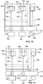
- the support assembly 10 can include telescoping legs 82 at intermediate corners 31 of the frame 18 between the rear corners 26 and the front corner 30.
- the legs 82 can be moved out of the path of the bottom plate 16 as the bottom plate is moved out from beneath the main tube 14, such as by using the swing arm 32 described above.
- each telescoping leg 82 includes an elongate shaft 83 with a cross bar 84 extending outwardly from an intermediate portion thereof and a caster 85 mounted on a distal end thereof.
- a telescoping housing 86 is mounted to the frame 18 at the corner 31.
- the housing 86 includes openings 87 extending through the top and bottom thereof so that the leg 82 can extend therethrough. If desired, the housing 86 can include bearings 88 disposed around the openings 87 to align and aid in movement of the leg 82.
- the housing 86 includes first and second position plates 89, 90 that extend across the interior of the housing 86.
- the first and second position plates 89, 90 each further include a key opening 91 that extends vertically therethrough that has a shape corresponding to the cross bar 84 of the leg 82.
- the first position plate 89 is disposed at a height so that with the cross-bar 84 positioned below the first position plate 89, as shown in Fig. 11 , the leg 82 is aligned with the other legs 24, 28 of the support assembly 10.
- the support assembly 10 in this configuration has five legs to support the weight of the column 12 and provides stable movement.
- the second position plate 90 is disposed above the first position plate 89 and is configured to hold the leg 82 in an elevated position out of the way for removal of the bottom plate 16.
- a user can align the cross bar 84 with the key opening 91 of the first position plate 89 and, subsequently, the key opening 91 of the second position plate 90. Thereafter, the user can rotate the leg 82 so that the cross bar 84 is not aligned with the key opening 91 and the weight of the leg 82 is supported on the second position plate 90.
- each leg 82 can include a handle 92 secured thereto to help a user to move the leg 82 to the elevated position.
- the corners 31 of the frame 18 can be utilized for the attachment of removable legs 93.
- the removable legs 93 include an elongate shaft 94, casters 95 mounted at a distal end of the shaft 94, and a coupling portion 96 at a proximal end of the shaft 94.
- the corners 31 include a corresponding coupling portion 97 so that the legs 93 can be removably secured thereto.
- the leg coupling portion 96 includes a threaded fastener 98 that can be inserted through a throughbore 99 extending through the frame 18 and into the proximal end of the shaft 88.
- the leg 93 can include a threaded fastener and the throughbore 99 can be threaded and/or a nut can secure the leg 93 to the frame 18. It will be understood that other coupling methods, such as snap-fit, friction, and so forth, are within the scope of this disclosure.
- Attaching and removing the removable legs 93 can be aided by frame lifting mechanisms, such as the hydraulics 54 discussed above. More specifically, the hydraulics 54 can lift the frame 18 to a raised position and the removable legs 93 can then easily be secured to the frame 18 as discussed above. Thereafter, the hydraulics 54 can lower the frame 18 until all of the legs 24, 28, 93 support the cylinder 12 for movement. When removal of the bottom plate 16 is desired, the frame 18 can then be lifted and the legs 93 removed so that the bottom plate 16 can be pivoted out between the front 28 and rear legs 24, as discussed above.
- frame lifting mechanisms such as the hydraulics 54 discussed above. More specifically, the hydraulics 54 can lift the frame 18 to a raised position and the removable legs 93 can then easily be secured to the frame 18 as discussed above. Thereafter, the hydraulics 54 can lower the frame 18 until all of the legs 24, 28, 93 support the cylinder 12 for movement. When removal of the bottom plate 16 is desired, the frame 18 can then be lifted and the legs 93 removed so that the bottom plate 16 can be pivoted out between
- the bottom plate 16 can be easily secured to the main tube 14 without the use of bolts as with the conventional method.
- the bottom plate 16 has a gear shaped configuration with an array of radially opening slots 150 extending through the bottom plate 16.
- the slots 150 have a curved interior end 152 with a rectangular radial opening 154 in the illustrated form, but other suitable configurations can be contemplated.
- the main tube 14 has a plurality of pendulum members 156 that are pivotably coupled to an exterior 158 of the main tube 14 at spaced radial positions.
- Each pendulum member 156 includes a stem portion 160, a distal, enlarged retaining portion 162, and a proximal end 164.
- Each pendulum member 156 can be coupled to the main tube 14 by any suitable method, including brackets 166 as shown.
- the pendulum members 102 are I-bars and the proximal end 164 is retained with the brackets 166 secured to the main tube 14 so that the pendulum members 156 can be pivoted along a vertical plane. So configured, to secure the bottom plate 16 to the main tube 14, a user can pivot each of the pendulum members 156 so that the retaining portions 162 are disposed below the bottom plate 16, which prevents the bottom plate 16 from being removed.
- the stem portion 160 of each pendulum member 156 is sized so that the retaining portion 162 can clear the bottom plate 16 when the plug portion 25 thereof is fully received within the main tube 14, i.e ., the hydraulic cylinders 54 are lowered to make the main tube 14 fully seat on the bottom plate 16 and compress a compliance gap 166. Thereafter, as a result of gravity, packing, or other operation, the plug portion 25 of the bottom plate 16 slides downwardly to expand the compliance gap 166 and abut the retaining portions 110 of the pendulum members 102.
- the seal between the plug portion 25 and the main tube 14 remains hermetic through this movement because the seal is an internal seal and the seal 77 is spaced from the bottom plate 16 a sufficient distance to allow for the expansion of the compliance gap 166.
- the pendulum members 102 capture the bottom plate 16 and secure the bottom plate 16 to the main tube 14 without the use of bolts.
- a lower outer corner 170 of the bottom plate 16 can be chamfered or rounded to reduce the arcuate path of the retaining portion 110 to pivot to a position below the bottom plate 16.
- the retaining portions 162 can have a flat radially inward surface 168 to provide a larger seating area for the bottom plate 16.
- the proximal end 164 of each pendulum member 156 can have a similar configuration as the retaining portion 162. With this configuration, the flat surface 168 can provide a distinguishing feature for a user installing the pendulum members 156.
- coupling brackets 172 can be mounted to the main tube 14 above the pivoting brackets 166.
- the coupling brackets 172 can be configured to retain the pendulum members 156 in a generally vertical orientation by clips, snap-fit, friction-fit, or other suitable methods.
- FIG. 18 A further embodiment for the column 12 is shown in Figs. 18 and 19 where the main tube 14 includes upper and lower slurry ports 200, 202.
- the bottom plate 16 is coupled to the main tube 14 and a piston 204 is driven downwardly to pack the bed 206 between the piston 204 and the bottom plate 16.
- a seal 208 of the piston 204 and the bottom plate seal 77 extend circumferentially around the piston 204 and bottom plate 16 respectively within a seal groove 210.
- the piston 204 and bottom plate 16 each further include a glide ring 212 disposed within a groove 214 extending circumferentially around the piston 204 and bottom plate 16 respectively.
- the piston 204 and bottom plate 16 can further include a scraper seal 216, a fritt 218, and a distributor plate 220 with a seal 222.
- the plug portion 25 of the bottom plate 16 has a larger depth than conventional plates so that the plug portion 25 projects further into the main tube 14. This additional depth can be utilized so that the seal 77 is driven past the lower slurry port 202 for operation.
- the glide ring 212 extends across the lower slurry port 202.
- the hydraulics 54 configuration described above can advantageously be utilized to drive the additional depth of the bottom plate 16 into the main tube 14.
- the piston 204 is driven downwardly within the main tube 14 so that the seal 208 is disposed below the upper slurry port 200 and the glide ring 212 extends across the upper slurry port 200. So configured, the lower and upper slurry ports 200, 202 are hidden to avoid disturbing the plug flow and to obtain better chromatography, i.e., higher plate count, HETP.
- the upper and lower slurry ports 200 can be utilized to re-slurry or process soft beds in the column 12. Additionally, the upper and lower slurry ports 200 can be utilized to transfer the bed 206 in a closed system. To utilize these features, the piston 204 is raised to expose the upper slurry port 200 and the bottom plate 16 is lowered to expose the lower slurry port 202, such as by use of the hydraulics 54 and removable couplings 81 described above.
Landscapes
- Chemical & Material Sciences (AREA)
- Analytical Chemistry (AREA)
- Health & Medical Sciences (AREA)
- General Physics & Mathematics (AREA)
- Physics & Mathematics (AREA)
- Chemical Kinetics & Catalysis (AREA)
- Pathology (AREA)
- General Health & Medical Sciences (AREA)
- Biochemistry (AREA)
- Immunology (AREA)
- Life Sciences & Earth Sciences (AREA)
- Clinical Laboratory Science (AREA)
- Engineering & Computer Science (AREA)
- Multimedia (AREA)
- Signal Processing (AREA)
- Treatment Of Liquids With Adsorbents In General (AREA)
- Accommodation For Nursing Or Treatment Tables (AREA)
Abstract
Description
- The present disclosure generally relates to chromatography and synthesis columns and, more particularly, to base assemblies and components for chromatography and synthesis columns.
- Chromatography and synthesis columns can be utilized for the large-scale purification of pharmaceuticals and fine chemicals. Columns for these uses can be quite heavy, including some that have a weight around 12,000 pounds. Routine maintenance for these columns may be required as often as every day and, even further, some facilities require that the columns be moved to a maintenance area. Columns of these types can typically sit low to the ground and have a 3 or 4 leg frame.
- Routine maintenance of the column may include removing the bottom plate, ejecting (unpacking) the bed (also known as the stationary phase), capturing the bed, cleaning/inspecting/replacing the bed supports, cleaning/inspecting/replacing the sealing components or scraper seals, inspecting and wiping down the interior column walls and slurry port, reassembling the column, processing the stationary phase, re-forming the bed (packing), and, if necessary, transporting the column back to a manufacturing area.
- For conventional columns, the bottom plate can be quite heavy, about 1,500 pounds, and is removed to perform one or more of the maintenance actions set forth above. By one removal approach, one or more people remove some of the bolts securing the bottom plate to the column and insert threaded rods with washers and nuts secured thereto in place of the removed bolts. The remaining bolts are then removed and jack screws are inserted in the perimeter of the bottom plate. At least four people can then repeatedly coordinate unscrewing the nuts on the threaded rods and screwing in the jack screws until the bottom plate falls onto the nuts on the threaded rods. The nuts on the threaded rods can then be unscrewed to provide a sufficient clearance between the bottom plate and the column. Thereafter, the jack screws are removed and a lift device, such as a fork lift, is brought in to lift the bottom plate enough to remove the threaded rods. The lift device must then carefully move the bottom plate to avoid damaging any of the components, which can be difficult due to the imprecise operation of many lift devices.
- One maintenance action involves removing the bed from the main tube after removal of the bottom plate. By one approach, a receiver can be rolled in underneath the main tube to capture the bed as it is ejected by the piston. With some configurations, the column may positioned too low to accommodate a receiver of sufficient depth to capture the entire height of the bed. To solve this problem, the bed may be partially ejected into the receiver by a pump cart forcing downward movement of the piston and a piano wire may be used to cut the bed at a midpoint.
- Assembly of the column after routine maintenance can largely be the reverse of disassembly, but can require more precision in the placement of the bottom plate by the lift device to align the bottom plate translationally, rotationally for the insertion of threaded rods and bolts, and horizontally with the main tube. Due to this complicated alignment, the column components or operators may be damaged by collision or pinch during the alignment and insertion of the heavy components. Further, the complicated process of utilizing the threaded rods and nuts to elevate and insert the bottom plate into the column can then again be performed.
- Accordingly, conventional procedures can be complicated, time-intensive, expensive in time and resources, and can, at times, pose unsafe situations for operations and column components.
- In accordance with a first aspect, a base assembly for a chromatography and synthesis column having a main tube and a bottom plate is disclosed that includes a frame that is secured to the main tube of the column, legs mounted to the frame to support the column in an upright orientation, and lifting mechanisms of each of the legs that are configured to raise and lower the frame.
- In accordance with one form, each of the legs can include a base, and the lifting mechanisms can be hydraulic cylinders where each hydraulic cylinder is supported by the base with a portion thereof engaging the frame. In accordance with a further form, the frame can include tubular leg portions extending downwardly toward the bases of the legs, where the hydraulic cylinders extend within the tubular leg portions. The legs can further include an upstanding wall that extends around a perimeter of the base, such that the upstanding wall is configured to telescope with the tubular leg portions as the hydraulic cylinders move the frame. In accordance with another form, the hydraulic cylinders can be double acting, double rod cylinders that are connected in series. In this form, the base assembly can include a control circuit that is configured to control operation of the hydraulic cylinders. In accordance with a further form, the control circuit can be an air driven hydraulic circuit and/or the control circuit can include a pendant having user inputs that are configured to lift and lower the tube by operating the hydraulic cylinders.
- In accordance with another form, the base assembly can further include a rigid swing arm that has a proximal end coupled to one of the legs and a distal end coupled to the bottom plate. The swing arm is configured to guide pivoting of the bottom plate along a horizontal plane. Further, one of the legs is spaced from at least another one of the legs a distance sized so that the bottom plate can be pivoted therebetween along a radius of the swing arm. In accordance with a further form, the base assembly can further include a carriage having the bottom plate mounted thereon. So configured, the bottom plate can be conveyed on the carriage and movement of the carriage can be directed by pivoting of the swing arm. In accordance with yet a further form, the base assembly can further include one or more removable couplings that are disposed between the bottom plate and the legs to hold the bottom plate stationary while the lifting mechanisms raise the main tube. The proximal end of the swing arm can include a bearing that coupled to the one of the legs and is configured to slide therealong.
- In accordance with another form, the frame has a pentagon shape that extends around a rectangular portion and a triangular portion. In this form, the legs can include two rear legs that are mounted at distal corners of the rectangular portion and a front leg that is mounted at a proximal corner of the triangular portion. In accordance with a further form, the base assembly can further include telescoping legs that are mounted at intermediate corners of the frame. Each of the legs and the telescoping legs can include casters that are mounted on ends thereof, such that the telescoping legs are configured to cooperate with the legs to provide stable movement of the column.
- In accordance with another form, the base assembly, in combination with the chromatography and synthesis column, can include a plurality of pendulum members that are pivotably mounted to the main tube. Each of the plurality of pendulum members can include a stem portion and a distal, enlarged retaining portion. The bottom plate can further include an array of radially opening slots, where each of the slots are aligned with one of the plurality of pendulum members. So configured, each of the pendulum members can be pivoted so that the stem portion extends through the respective slot and the retaining portion is disposed below the bottom plate and configured to abut a bottom surface of the bottom plate to retain the bottom plate on the main tube. In accordance with a further form, the bottom plate can include a plug portion that is configured to extend into the main tube and seal to an interior surface of the main tube. The stem portion can then be sized so that the retaining portion clears the bottom plate when pivoted only when the plug portion is fully received within the main tube. In accordance with a further form, a lower, radially outward corner of the bottom plate can be chamfered to provide clearance for the retaining portion of the pendulum.
- In accordance with a second aspect, a base assembly for a chromatography and synthesis column having a main tube and a bottom plate is disclosed that includes a frame that is secured to the main tube of the column, legs mounted to the frame to support the column in an upright orientation, and a rigid swing arm that has a proximal end mounted to one of the legs and a distal end mounted to the bottom plate. The swing arm is configured to guide pivoting of the bottom plate along a horizontal plane. The one of the legs is spaced from at least another one of the legs a distance sized so that the bottom plate can be pivoted therebetween along a radius of the swing arm.
- In accordance with one form, the base assembly can further include a carriage having the bottom plate mounted thereto, such that the bottom plate can be conveyed on the carriage and movement of the carriage can be directed by pivoting of the swing arm.
- In accordance with another form, the frame can have a pentagon shape extending around a rectangular portion and a triangular portion and the legs can include two rear legs mounted at distal corners of the rectangular portion and a front leg mounted at a proximal corner of the triangular portion. So configured, the proximal end of the swing arm can be mounted to the front leg.
- In accordance with another form, the frame can have a rectangular shape with the legs mounted to corners of the frame.
- In accordance with a third aspect, a method of servicing a chromatography and synthesis column is disclosed, where the column includes a main tube and a bottom plate and is supported by a base assembly that has a frame mounted to the main tube and legs mounted to the frame. The method includes uncoupling the bottom plate from the main tube, operating lifting mechanisms of each of the legs to raise the frame and the main tube, and moving the bottom plate out from underneath the main tube.
- In accordance with one form, uncoupling the bottom plate from the main tube can include pivoting a plurality of pendulum members that include a stem portion and a distal, enlarged retaining portion about pivot connections with the main tube from a first position where the retaining portions are disposed below the bottom plate to a second position where the retaining portions are disposed outwardly of or above the bottom plate. In accordance with a further form, pivoting the plurality of pendulum members from the first position can include pivoting the plurality of pendulum members from a first position where the stem portions extend through radially opening slots in the bottom plate and the retaining portions are disposed below the bottom plate. In accordance with a further form, uncoupling the bottom plate from the main tube can further include operating the lifting mechanisms of each of the legs to lower the frame so that a plug portion of the bottom plate is fully received within the main tube. In accordance with a further form, uncoupling the bottom plate from the main tube can include releasably coupling the bottom plate to a plurality of the legs such that operating the lifting mechanisms of each of the legs to raise the frame and the main tube displaces a plug portion of the bottom plate from a sealing position within the main tube.
- In accordance with another form, operating the lifting mechanisms of each of the legs top raise the frame and the main tube can include operating hydraulic cylinders of each of the legs having a portion thereof engaging the frame. In accordance with a further form, operating the hydraulic cylinders of each of the legs comprises operating double acting, double rod cylinders connected in series with an air driven hydraulic control circuit. In accordance with yet a further form, operating the double acting, double rod cylinders connected in series with the air driven hydraulic control circuit can include operating a pneumatic valve of a pendant.
- In accordance with another form, moving the bottom plate out from underneath the main tube can include pivoting the bottom plate along a horizontal plane guided by a rigid swing arm having a proximal end coupled to one of the legs and a distal end coupled to the bottom plate between the one of the legs and another one of the legs. In accordance with a further form, the bottom plate can be mounted on a carriage and pivoting the bottom plate can include conveying the bottom plate on the carriage along a path directed by pivoting of the swing arm. In accordance with a further form, the frame can have a pentagon shape and the legs can include three legs mounted to three corners of the frame and two telescoping legs mounted to intermediate corners of the frame, and the method can further include shifting the telescoping legs to a lowered position from a raised position such that each of the legs and the removable legs support the main tube. In accordance with a further form, the method can further include pivoting the bottom plate along the horizontal plane guided by the rigid swing underneath the main tube until the bottom plate abuts an alignment stop configured to align a plug portion of the bottom plate with the main tube. In accordance with a further form, the method can further include operating lifting mechanisms of each of the legs to lower the frame and the main tube so that the plug portion of the bottom plate is inserted into the main tube to seal against an interior surface thereof and coupling the bottom plate to the main tube.
- The features of this disclosure which are believed to be novel are set forth with particularity in the appended claims. The present disclosure may be best understood by reference to the following description taken in conjunction with the accompanying drawings, in which like reference numerals identify like elements in the several figures, in which:
-
Figure 1 is a perspective view of a chromatography and synthesis column and base assembly in accordance with various embodiments; -
Figure 2 is a side cross-sectional view of a leg assembly for a base assembly showing a hydraulic cylinder in accordance with various embodiments; -
Figure 3 is a side cross-sectional view of a leg assembly for a base assembly showing a hydraulic cylinder and swing arm in accordance with various embodiments; -
Figure 4 is a side cross-sectional view of a leg assembly for a base assembly showing a guide block in accordance with various embodiments; -
Figure 5 is a side elevational view of the chromatography and synthesis column and base assembly ofFig. 10 with the removable leg mounted thereto in accordance with various embodiments; -
Figure 6 is a side cross-sectional schematic view of a hydraulic cylinder system in accordance with various embodiments; -
Figure 7 is a top schematic view of a chromatography and synthesis column and base assembly with a swing arm configured to guide pivoting of a bottom plate in accordance with various embodiments; -
Figure 8 is a top schematic view of an alternative chromatography and synthesis column and base assembly with a swing arm configured to guide pivoting of a bottom plate in accordance with various embodiments; -
Figure 9 is a side elevational view of a chromatography and synthesis column and base assembly with a telescoping leg in accordance with various embodiments; -
Figure 10 is a top cross-sectional view of the telescoping leg ofFig. 7 in accordance with various embodiments; -
Figure 11 is a side cross-sectional view of the telescoping leg ofFig. 7 in accordance with various embodiments; -
Figure 12 is a side elevational view of a chromatography and synthesis column and base assembly with a removable leg being mounted thereto in accordance with various embodiments; -
Figure 13 is a diagrammatic view of an air driven hydraulic control circuit in accordance with various embodiments; -
Figure 14 is a top plan view of a bottom plate for a chromatography and synthesis column with radially opening slots in accordance with various embodiments; -
Figure 15 is a side plan view of a chromatography and synthesis column including the bottom plate ofFig. 14 and a main tube showing pendulum members to secure the bottom plate to the main tube in accordance with various embodiments; -
Figure 16 is a sectional side view of the chromatography and synthesis column ofFig. 15 in accordance with various embodiments; -
Figure 17 is a sectional side view of the chromatography and synthesis column ofFig. 15 in accordance with various embodiments; -
Figure 18 is a side cross-sectional view of a chromatography and synthesis column with a bottom plate inserted to cover a slurry port in accordance with various embodiments; and -
Figure 19 is a side cross-sectional view the chromatography and synthesis column ofFig. 18 in accordance with various embodiments. - Skilled artisans will appreciate that elements in the figures are illustrated for simplicity and clarity and have not necessarily been drawn to scale. For example, the dimensions and/or relative positioning of some of the elements in the figures may be exaggerated relative to other elements to help to improve understanding of various embodiments of the present invention. Also, common but well-understood elements that are useful or necessary in a commercially feasible embodiment are often not depicted in order to facilitate a less obstructed view of these various embodiments. It will further be appreciated that certain actions and/or steps may be described or depicted in a particular order of occurrence while those skilled in the art will understand that such specificity with respect to sequence is not actually required. It will also be understood that the terms and expressions used herein have the ordinary technical meaning as is accorded to such terms and expressions by persons skilled in the technical field as set forth above except where different specific meanings have otherwise been set forth herein.
- The present disclosure is generally directed to chromatography and synthesis columns, assemblies, components, and methods of assembly and disassembly. The chromatography and synthesis columns as provided herein can be easily assembled and disassembled for maintenance saving time and potential damage to the columns. The chromatography and synthesis columns can further be provided with a stable base for securely moving the columns.
- An
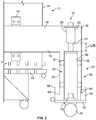
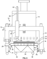
exemplary support assembly 10 for a chromatography andsynthesis column 12 that includes a generally annularmain tube 14 and abottom plate 16 is described with reference toFigs. 1-12 . As shown inFig. 2 , in one form, thesupport assembly 10 includes arigid frame 18 that has a house-shaped pentagon configuration withcross-members 19 extending around a rearrectangular portion 20 and a forwardtriangular portion 22. In the illustrated form, theframe 18 is sized to extend around thecolumn 12 such that thecolumn 12 is disposed both within the rectangular andtriangular portions - The
support assembly 10 further includes tworear legs 24 that are mounted to theframe 18 atrear corners 26 of therectangular portion 20 and afront leg 28 mounted to theframe 18 at aforward corner 30 of thetriangular portion 22. As shown, theframe 18 is configured so that theforward corner 30 andfront leg 28 align with a midpoint of theframe cross-member 19 extending between therear corners 26. Further, in one form, thefront leg 28 is set a distance from thecolumn 12 generally equal to the closest perpendicular spacing of thecolumn 12 to the threecross-members 19 of theframe 18 in therectangular portion 20. - In some embodiments, the
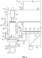
support assembly 10 can be configured to lift thecolumn 12 to thereby ease removal of thebottom plate 16 and other maintenance actions. To accomplish this, as shown inFigs. 1-6 , theframe 18 is secured to themain tube 14 usingbrackets 44 or other suitable methods, such as welding, andlower leg assemblies rear legs 24 andfront leg 28, respectively, cooperate to lift theframe 18 and thecolumn 12 secured thereto. - As shown in
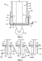
Figs. 2-4 , thelower leg assemblies rear legs 24 andfront leg 28 include abase 50, acaster 52 mounted to an underside of thebase 50, ahydraulic cylinder 54 including abarrel 55 and apiston rod 57, and asupport 56 disposed between the base 50 and thehydraulic cylinder 54. Thebase 50 andsupport 56 are sized to position thehydraulic cylinder 54 so that movement of thepiston rod 57 results in a desired amount of upward or downward movement of theframe 18 and themain tube 14. So configured, thelower leg assemblies frame 18 by raising and lowering thepiston rod 57 of thehydraulic cylinder 54. In the illustrated form, thehydraulic cylinders 54 are inverted with thebarrel 55 coupled to theframe 18. This advantageously avoids movement of hydraulic hoses and other components relative to theframe 18. - In order to orient and couple the
lower leg assembly 46 to theframe 18, theframe 18 includes downwardly dependingtubular leg portions 58 disposed at thecorners vertical sidewall 59 extending around an interior 60 thereof. Theleg portions 58 are sized so that thesupport 56 and thehydraulic cylinder 54 can extend upwardly into the interior 60 thereof.Bearings 61 are disposed along the height of and coupled to thesupport 56 to contact theleg portion sidewall 59 to orient thelower leg assembly 46 within theframe leg portion 58 as thehydraulic cylinder 54 moves theframe 18 upwardly and downwardly. - To further ensure that the
frame leg portion 58 is aligned with thebase 50, thebase 50 can include ablock 62 having avertical slot 64 extending through a portion thereof. Theblock 62 is positioned on the base 50 so that thesidewall 59 of theleg portion 58 shifts therein during lifting and lowering operations. Further, theblock 62 can be configured to prevent thelower leg assembly frame 18. - In order to shield the moving components of the
support assembly 10 during lifting and lowering operations, thebase 50 can include anupstanding wall 66 that extends around a perimeter thereof. As shown, thewall 66 is spaced outwardly of thesidewall 59 of theleg portions 58 and has a height to project above alower edge 68 of theleg portions 58 with thehydraulic cylinder 54 in a raised configuration. So configured, theleg portion 58 and thewall 66 telescope with respect to one another during lifting and lower operations, which effectively prevents a user from inadvertently putting a hand or other object underneath theframe 18. - By a further approach, as shown in
Fig. 4 , theleg assemblies height guide member 70 that is slidable along thebase 50. Theguide member 70 includes raisedportions 71 that project upwardly towards theframe 18. The raisedportions 71 are configured so that when theleg portion 58 is lowered, thelower edge 68 abuts atop surface 72 of the raisedportion 71 resulting in theframe 18 being disposed at a height suitable for operation. For storage, a user can slide theheight guide member 70 so that the raisedportions 71 are misaligned with respect to thesidewall 59 and a lowering operation causes theedge 68 to abut alower surface 73 of theguide member 70. As shown inFig. 4 , theupstanding wall 66 of the base 50 can includeopenings 74 extending therethrough to allow theguide member 70 to be slid to a desired position on thebase 50. Further, to keep theguide member 70 disposed on thebase 50, theguide member 50 can include end stops 75 that are configured to abut theupstanding wall 66 orbase 50 when theguide member 50 is slid from one end to the other. By one approach, the end stops 75 can be utilized to position theguide member 70 in the raised or lowered configurations, allow a user to simply shift theguide member 70 until the desiredend stop 75 prevents further movement. - Due to the high precision required to insert and remove the
bottom plate 16, by one approach, thehydraulic cylinders 54 can be configured to operate in lockstep, providing synchronized up and down movement of theframe 18 and, therefore, themain tube 14. The asymmetrical loading on the three liftingleg assemblies column 12 within theframe 18 makes synchronized movement more difficult. - To accomplish a coordinated lift, as shown in
Fig. 5 , thehydraulic cylinders 54 can be double acting cylinders. The double rod configuration makes the area of the exposedpiston 100 equal in eachchamber double acting cylinder 54. This allows one pump 106 (Fig. 6 ) to synchronizemultiple cylinders 54 and provide the coordinated descent of thecylinders 54 when there is an uneven load distributed across thecylinders 54. As illustrated inFig. 5 , thecylinders 54 are connected in series. A firstclosed system 108, which is filled with a hydraulic fluid as understood, is established between thetop chamber 102 of thefirst cylinder 54a and thebottom chamber 104 of thesecond cylinder 54b. A secondclosed system 110 is established between thetop chamber 102 of thesecond cylinder 54b and thebottom chamber 104 of thethird cylinder 54c. As thebottom chamber 104 of thefirst cylinder 54a is being filled by hydraulic fluid, thetop chamber 102 of thefirst cylinder 54a will fill thebottom chamber 104 of thesecond cylinder 54b. As thebottom chamber 104 of thesecond cylinder 54b is being filled, thetop chamber 102 of thesecond cylinder 54b will fill thebottom chamber 104 of thethird cylinder 54c. As thebottom chamber 104 of thethird cylinder 54c is being filled, thetop chamber 102 will express hydraulic fluid into areservoir 112 supplying thepump 106 for thefirst cylinder 54a. While this hydraulic configuration of thesystem 108 is inefficient relative to traditional hydraulic cylinders, the double rod configuration of thecylinders 54 reduces the area of exposedpiston 100 and thecylinders 54 in series adds the load on all of thecylinders 54 together and applies the total load to the reduced area of thepiston 100 of thefirst cylinder 54a. This disadvantage can be tolerated because while thecolumns 12 are large, thehydraulic cylinders 54 are more than sufficient to handle the load, and operating thecylinders 54 in sync provides a significant advantage of perfectlysynchronized cylinders 54 moving theframe 18, and thecolumn 12 secured thereto, upwardly and downwardly. - The reverse operations happen when lowering the
frame 18. The load of thecolumn 12 andframe 18 is used to drive thecylinders 54 downwardly and, as shown inFig. 9 , ametering valve 114 on thefirst cylinder 54a defines the rate of descent of all thecylinders 54. The load pushing down on thethird cylinder 54c causes thebottom chamber 104 to fill thetop chamber 102 of thesecond cylinder 54b. At the same time, thetop chamber 102 of thethird cylinder 54a is filling by suction of the fluid in thereservoir 112 supplying thepump 106. Thetop chamber 102 of thesecond cylinder 54b being filled by thethird cylinder 54c and the load on the second andthird cylinders bottom chamber 104 of thesecond cylinder 54b to fill thetop chamber 102 of thefirst cylinder 54a. Thetop chamber 102 of thefirst cylinder 54a being filled by thesecond cylinder 54b and the load on the first, second andthird cylinders 54 causes thebottom chamber 104 of thefirst cylinder 54a to express fluid. Themetering valve 114 put on the fluid flow from thebottom chamber 104 of thefirst cylinder 54a defines the rate of descent of all threecylinders 54. So configured, the threecylinders 54 work in lockstep to move theframe 18 andcolumn 12 upwardly and downwardly. -
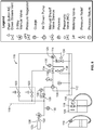
Fig. 9 is a process and instrument diagram for an example air-drivenhydraulic control circuit 116. As shown, thecontrol circuit 116 is provided for driving movement of thecylinders 54 by controlling operation of thepump 106. In the illustrated form, thepump 106 is an air-over-hydraulic pump and thecontrol circuit 116 is air driven. It will be understood that other circuits, including electrical, could alternatively be utilized to accomplish the hydraulic pump and control circuit. By one approach, a user can provide input to thecontrol circuit 116 using a pendent 118 havingpushbutton vents 120 to provide convenience for the operator and to facilitate one-man operation. It will be understood that the valve components of the pendent 118 can be located elsewhere and/or alternative embodiments for the circuit can perform the same or similar functions. - The
control circuit 116 includes aninlet 122 from anair supply 123 suitable to drive thepump 106 to the pressure required by thecylinders 54 to lift theframe 18 andcolumn 12 and anoutlet 124 connected to thecylinders 54. As shown, thecontrol circuit 116 can further utilize a 3-waymanual valve 126 as an on/off control, apressure regulator 128,various pressure gauges 130, a manual shut-offservice valve 132,pneumatic valves 134, and apressure relief valve 136. - With the
control circuit 116 shown inFig. 9 , movement of thecylinders 54 can be locked out by the on/offvalve 126 which simultaneously vents the pneumatics whether thecylinders 54 are moving or sitting idle. Afirst pressure gauge 130 is included so the inlet air pressure can be confirmed when the on/offvalve 126 is in the on position and that the pneumatic pressure is vented when the on/offvalve 126 is in the off position. The pendent 118 has twopneumatic valves 120 that are normally closed. To lower theframe 18 andcolumn 12, the "down"valve 120 is in communication with the on/offvalve 126 and the actuator of thedown shutoff valve 134. To raise theframe 12 andcolumn 12, the "up"valve 120 is in communication with the on/offvalve 126 and the actuator of the up-shutoff valve 134. Thepressure regulator 128 is in communication with the on/offvalve 126 and the air side of the air drivenpump 106. Asecond gauge 130 is in communication with thepressure regulator 128 and the air side of the air drivenpump 106. The liquid side of the air drivenpump 106 is in communication with the fluid in thehydraulic fluid reservoir 112 and the up-shutoff valve 134. Thepressure relief valve 136 is in communication with thehydraulic fluid reservoir 112, the up-shutoff valve 134, themetering valve 114, and theoutput 124 to thehydraulic cylinders 54. Athird pressure gauge 130 is in communication with the up-shutoff valve 134, thepressure relief valve 136, themetering valve 114, and theoutput 124 to thehydraulic cylinders 54. - As discussed above, the
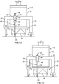
bottom plate 16 of thecolumn 12 is removed for many maintenance actions. In order to easily and repeatably move thebottom plate 16 from underneath themain tube 14 and realign thebottom plate 16 with themain tube 14, aswing arm 32 is provided that pivotably couples thebottom plate 16 to thesupport assembly 10 at thefront support leg 28 via a bearing 29 (Fig. 3 ). Theswing arm 32 is rigid so that thebottom plate 16 can be pivoted along a set radius from thefront support leg 28. Advantageously, as shown inFig. 7 , the three-legged configuration of thesupport assembly 10 provides sufficient clearance between thefront leg 28 and therear legs 24 so that thebottom plate 16 can easily pass therebetween. - In an alternative embodiment as shown in
Fig. 8 , a frame 18' can have a rectangular configuration where thelegs 24 are spaced a sufficient distance from one another for thebottom plate 16 to be pivoted between two adjacent legs by a rigid swing arm 32'. While this configuration may be suitable for many purposes, the footprint of the frame 18' is larger in comparison to the size of thecolumn 12 as with the above embodiment. - By one approach, as shown in
Fig. 9 , to aid in moving thebottom plate 16, thebottom plate 16 can be mounted to acarriage 34 having a housing 36 or other supporting framework andcasters 38. Thecarriage 34 allows the weight of thebottom plate 16 to be supported on thecasters 38 rather than a separate lifting device, such as a fork lift. With this configuration, a user can easily maneuver thecarriage 34 on thecasters 38, which avoids the precarious movements of a lift device. Moreover, thecarriage 34, along with theswing arm 32, ensures that movement of thebottom plate 16 is precisely controlled along the radius of theswing arm 32 so that contact, and any resulting damage, between thebottom plate 16 and thesupport assembly 10 is prevented. - As discussed above, moving the
bottom plate 16 back underneath the main 14 to insert aplug portion 25 thereof into themain tube 14 requires that thebottom plate 16 be aligned translationally, rotationally, and horizontally with themain tube 14. Theswing arm 32 advantageously provides easy, repeatable alignment because thebottom plate 16 can be fixedly mounted to theswing arm 32 so that theplate 16 cannot rotate relative to theswing arm 32 and theswing arm 32, andcarriage 34, can maintain thebottom plate 16 in an horizontal orientation. Further, astop 39 can be mounted to thesupport assembly 10 and/or themain tube 14 so that an inwardly facingsurface 40 of thestop 39 positions thebottom plate 16 in translational alignment with themain tube 14 when thebottom plate 16 abuts thesurface 40. So configured, a user can simply push thebottom plate 16 on thecarriage 34 and theswing arm 32 will direct movement along the radius thereof until thebottom plate 16 contacts thestop 39. - A lifting mechanism, such as the
hydraulics 54 discussed above, can further be utilized to reliably remove thebottom plate 16 from themain tube 14. As discussed above, thebottom plate 16 includes aplug portion 25 that projects into and seals against aninterior surface 76 of themain tube 14 with one or more seals 77. As shown inFig. 9 , thelower leg assemblies anchor 78, such as a ring as illustrated, and thebottom plate 16 can include acorresponding anchor 80. A removable orreleasable coupling 81 can then be installed between theanchors bottom plate 16 to thelower leg assemblies frame 18 is in the lowered position holding thebottom plate 16 in a fixed position. In the illustrated form, the threecouplings 81 to the rear andfront legs bottom plate 16, so that, when thehydraulic cylinders 54 raise theframe 18, thebottom plate 16 andcarriage 34 remain stationary. As themain tube 14 is raised, theplug portion 25 is pulled from within themain tube 14 until theplug portion 25 has sufficient clearance from themain tube 14. Thereafter, thecouplings 81 can be removed or released and thebottom plate 16 can be pivoted on theswing arm 32 to a position exterior of theframe 18 through the spacing between the front andrear legs anchors couplings 81 can take any suitable form, such as hooks, straps, fasteners, and so forth. Further, in another form, thecarriage 34 can include one or more of theanchors 78 rather than thebottom plate 16. - Referring back to
Fig. 3 , due to theswing arm 32, thelower leg assembly 48 of thefront leg 28 can be modified relative to therear legs 24 to include structure in addition to the components described above. More specifically, thelower leg assembly 48 includes alower support 51 andbase 53, with thecaster 52 mounted to thelower base 53. Thelower support 51 has a cylindrical configuration and is sized so that the bearing 29 of theswing arm 32 coupled thereto can freely rotate and has room to move upwardly and downwardly as thehydraulic cylinders 54 move theframe 18. - As is understood,
support assemblies 10 having three legs may result in less stable movement for thecolumn 12, especially where the weight of thecolumn 12 has asymmetrical loading as with theframe 18 discussed above. To provide additional support, as shown inFigs. 9-11 , thesupport assembly 10 can includetelescoping legs 82 atintermediate corners 31 of theframe 18 between therear corners 26 and thefront corner 30. By having a telescoping functionality, thelegs 82 can be moved out of the path of thebottom plate 16 as the bottom plate is moved out from beneath themain tube 14, such as by using theswing arm 32 described above. - As shown in
Figs 10 and 11 , eachtelescoping leg 82 includes anelongate shaft 83 with across bar 84 extending outwardly from an intermediate portion thereof and acaster 85 mounted on a distal end thereof. A telescopinghousing 86 is mounted to theframe 18 at thecorner 31. Thehousing 86 includesopenings 87 extending through the top and bottom thereof so that theleg 82 can extend therethrough. If desired, thehousing 86 can includebearings 88 disposed around theopenings 87 to align and aid in movement of theleg 82. - As shown, the
housing 86 includes first andsecond position plates housing 86. The first andsecond position plates key opening 91 that extends vertically therethrough that has a shape corresponding to thecross bar 84 of theleg 82. Thefirst position plate 89 is disposed at a height so that with the cross-bar 84 positioned below thefirst position plate 89, as shown inFig. 11 , theleg 82 is aligned with theother legs support assembly 10. As such, thesupport assembly 10 in this configuration has five legs to support the weight of thecolumn 12 and provides stable movement. Thesecond position plate 90 is disposed above thefirst position plate 89 and is configured to hold theleg 82 in an elevated position out of the way for removal of thebottom plate 16. To move theleg 82 to the elevated position, a user can align thecross bar 84 with thekey opening 91 of thefirst position plate 89 and, subsequently, thekey opening 91 of thesecond position plate 90. Thereafter, the user can rotate theleg 82 so that thecross bar 84 is not aligned with thekey opening 91 and the weight of theleg 82 is supported on thesecond position plate 90. If desired, eachleg 82 can include ahandle 92 secured thereto to help a user to move theleg 82 to the elevated position. - By another approach, in order to provide increased stability for the
support assembly 10, thecorners 31 of theframe 18 can be utilized for the attachment ofremovable legs 93. Theremovable legs 93 include anelongate shaft 94,casters 95 mounted at a distal end of theshaft 94, and acoupling portion 96 at a proximal end of theshaft 94. Thecorners 31 include acorresponding coupling portion 97 so that thelegs 93 can be removably secured thereto. In the illustrated form, theleg coupling portion 96 includes a threadedfastener 98 that can be inserted through athroughbore 99 extending through theframe 18 and into the proximal end of theshaft 88. By another approach, theleg 93 can include a threaded fastener and thethroughbore 99 can be threaded and/or a nut can secure theleg 93 to theframe 18. It will be understood that other coupling methods, such as snap-fit, friction, and so forth, are within the scope of this disclosure. - Attaching and removing the
removable legs 93 can be aided by frame lifting mechanisms, such as thehydraulics 54 discussed above. More specifically, thehydraulics 54 can lift theframe 18 to a raised position and theremovable legs 93 can then easily be secured to theframe 18 as discussed above. Thereafter, thehydraulics 54 can lower theframe 18 until all of thelegs cylinder 12 for movement. When removal of thebottom plate 16 is desired, theframe 18 can then be lifted and thelegs 93 removed so that thebottom plate 16 can be pivoted out between the front 28 andrear legs 24, as discussed above. - In a further embodiment shown in
Figs. 14-17 , thebottom plate 16 can be easily secured to themain tube 14 without the use of bolts as with the conventional method. As shown inFig. 14 , thebottom plate 16 has a gear shaped configuration with an array of radially openingslots 150 extending through thebottom plate 16. Theslots 150 have a curvedinterior end 152 with a rectangularradial opening 154 in the illustrated form, but other suitable configurations can be contemplated. - As shown in
Figs. 15-17 , themain tube 14 has a plurality ofpendulum members 156 that are pivotably coupled to anexterior 158 of themain tube 14 at spaced radial positions. Eachpendulum member 156 includes astem portion 160, a distal, enlarged retainingportion 162, and aproximal end 164. Eachpendulum member 156 can be coupled to themain tube 14 by any suitable method, includingbrackets 166 as shown. For example, in the illustrated form, thependulum members 102 are I-bars and theproximal end 164 is retained with thebrackets 166 secured to themain tube 14 so that thependulum members 156 can be pivoted along a vertical plane. So configured, to secure thebottom plate 16 to themain tube 14, a user can pivot each of thependulum members 156 so that the retainingportions 162 are disposed below thebottom plate 16, which prevents thebottom plate 16 from being removed. - By one approach, the
stem portion 160 of eachpendulum member 156 is sized so that the retainingportion 162 can clear thebottom plate 16 when theplug portion 25 thereof is fully received within themain tube 14, i.e., thehydraulic cylinders 54 are lowered to make themain tube 14 fully seat on thebottom plate 16 and compress acompliance gap 166. Thereafter, as a result of gravity, packing, or other operation, theplug portion 25 of thebottom plate 16 slides downwardly to expand thecompliance gap 166 and abut the retainingportions 110 of thependulum members 102. The seal between theplug portion 25 and themain tube 14 remains hermetic through this movement because the seal is an internal seal and theseal 77 is spaced from the bottom plate 16 a sufficient distance to allow for the expansion of thecompliance gap 166. As a result, thependulum members 102 capture thebottom plate 16 and secure thebottom plate 16 to themain tube 14 without the use of bolts. By one approach, a lowerouter corner 170 of thebottom plate 16 can be chamfered or rounded to reduce the arcuate path of the retainingportion 110 to pivot to a position below thebottom plate 16. If desired, the retainingportions 162 can have a flat radiallyinward surface 168 to provide a larger seating area for thebottom plate 16. As shown inFigs. 16 and 17 , theproximal end 164 of eachpendulum member 156 can have a similar configuration as the retainingportion 162. With this configuration, theflat surface 168 can provide a distinguishing feature for a user installing thependulum members 156. - Similarly, to remove the
bottom plate 16, a user can lower themain tube 14, or raise thebottom plate 16, so that theplug portion 25 is inserted further therein and thecompliance gap 166 is reduced. With this insertion, the retainingportions 162 will be spaced from thebottom plate 16, which allows a user to pivot thependulum members 156 to a storage position spaced radially from or disposed above thebottom plate 16. By one approach,coupling brackets 172 can be mounted to themain tube 14 above the pivotingbrackets 166. Thecoupling brackets 172 can be configured to retain thependulum members 156 in a generally vertical orientation by clips, snap-fit, friction-fit, or other suitable methods. - A further embodiment for the
column 12 is shown inFigs. 18 and19 where themain tube 14 includes upper andlower slurry ports bottom plate 16 is coupled to themain tube 14 and apiston 204 is driven downwardly to pack thebed 206 between thepiston 204 and thebottom plate 16. Aseal 208 of thepiston 204 and thebottom plate seal 77 extend circumferentially around thepiston 204 andbottom plate 16 respectively within aseal groove 210. Thepiston 204 andbottom plate 16 each further include aglide ring 212 disposed within agroove 214 extending circumferentially around thepiston 204 andbottom plate 16 respectively. As shown, thepiston 204 andbottom plate 16 can further include ascraper seal 216, afritt 218, and adistributor plate 220 with aseal 222. - In this embodiment, the
plug portion 25 of thebottom plate 16 has a larger depth than conventional plates so that theplug portion 25 projects further into themain tube 14. This additional depth can be utilized so that theseal 77 is driven past thelower slurry port 202 for operation. In the illustrated form, theglide ring 212 extends across thelower slurry port 202. Thehydraulics 54 configuration described above can advantageously be utilized to drive the additional depth of thebottom plate 16 into themain tube 14. - Similarly, the
piston 204 is driven downwardly within themain tube 14 so that theseal 208 is disposed below theupper slurry port 200 and theglide ring 212 extends across theupper slurry port 200. So configured, the lower andupper slurry ports - Advantageously, the upper and
lower slurry ports 200 can be utilized to re-slurry or process soft beds in thecolumn 12. Additionally, the upper andlower slurry ports 200 can be utilized to transfer thebed 206 in a closed system. To utilize these features, thepiston 204 is raised to expose theupper slurry port 200 and thebottom plate 16 is lowered to expose thelower slurry port 202, such as by use of thehydraulics 54 andremovable couplings 81 described above. - Those skilled in the art will recognize that a wide variety of modifications, alterations, and combinations can be made with respect to the above described embodiments without departing from the scope of the disclosure, and that such modifications, alterations, and combinations are to be viewed as being within the ambit of the inventive concept. Further, one or more of the above components, assemblies, and embodiments can be utilized to retrofit current columns to provide the features and advantages described herein.
Claims (15)
- A base assembly for a chromatography column having a main tube and a bottom plate, the base assembly comprising:a frame secured to the main tube of the chromatography column;legs mounted to the frame to support the chromatography column in an upright orientation; andlifting mechanisms of each of the legs configured to raise and lower the frame.
- The base assembly of claim 1, wherein each of the legs comprise a base, and the lifting mechanisms comprise hydraulic cylinders, each hydraulic cylinder supported by the base with a portion thereof engaging the frame, wherein optionally
the frame comprises tubular leg portions extending downwardly toward the bases of the legs, the hydraulic cylinders extending within the tubular leg portions, and the legs further comprise an upstanding wall extending around a perimeter of the base, the upstanding wall configured to telescope with the tubular leg portions as the hydraulic cylinders move the frame, and further wherein optionally
the legs further comprise one or more bearings configured to orient the hydraulic cylinders within the tubular leg portions of the frame. - The base assembly of claim 2, wherein the hydraulic cylinders comprise double acting, double rod cylinders connected in series, and further comprising a control circuit configured to control operation of the hydraulic cylinders, wherein optionally:(a) the control circuit comprises an air driven hydraulic circuit, or(b) the control circuit comprises a pendant having user inputs configured to lift and lower the main tube by operating the hydraulic cylinders.
- The base assembly of claim 1, further comprising a rigid swing arm having a proximal end coupled to one of the legs and a distal end coupled to the bottom plate, the swing arm configured to guide pivoting of the bottom plate along a horizontal plane, and wherein the one of the legs is spaced from at least another one of the legs a distance sized so that the bottom plate can be pivoted therebetween along a radius of the swing arm, optionally further comprising
a carriage and wherein the bottom plate is mounted on the carriage, such that the bottom plate can be conveyed on the carriage and movement of the carriage can be directed by pivoting of the swing arm, and optionally further comprising:one or more removable couplings disposed between the bottom plate and the legs to hold the bottom plate stationary while the lifting mechanisms raise the main tube, and wherein the proximal end of the swing arm comprises a bearing coupled to the one of the legs and configured to slide therealong. - The base assembly of claim 1, wherein the frame has a pentagon shape extending around a rectangular portion and a triangular portion, and the legs comprise two rear legs mounted at distal corners of the rectangular portion and a front leg mounted at a proximal corner of the triangular portion, and optionally further comprising
telescoping legs mounted at intermediate corners of the frame, each of the legs and the telescoping legs comprising casters mounted on ends thereof, such that the telescoping legs are configured to cooperate with the legs to provide stable movement of the chromatography column. - The base assembly of claim 1 in combination with the chromatography column, the combination further comprising a plurality of pendulum members pivotably mounted to the main tube, each of the plurality of pendulum members comprising a stem portion and a distal, enlarged retaining portion, and
wherein the bottom plate includes an array of radially opening slots, each of the slots aligned with one of the plurality of pendulum members, each of the pendulum members configured to be pivoted so that the stem portion extends through the respective slot and the retaining portion is disposed below the bottom plate and configured to abut a bottom surface of the bottom plate to retain the bottom plate on the main tube, and wherein optionally(a) the bottom plate includes a plug portion configured to extend into the main tube and seal to an interior surface of the main tube, and the stem portion is sized so that the retaining portion clears the bottom plate when pivoted only when the plug portion is fully received within the main tube, or(b) a lower, radially outward corner of the bottom plate is chamfered to provide clearance for the retaining portion of the pendulum. - A base assembly for a chromatography column having a main tube and a bottom plate, the base assembly comprising:a frame secured to the main tube of the chromatography column;legs mounted to the frame to support the chromatography column in an upright orientation;a rigid swing arm having a proximal end mounted to one of the legs and a distal end mounted to the bottom plate, the swing arm configured to guide pivoting of the bottom plate along a horizontal plane, andwherein the one of the legs is spaced from at least another one of the legs a distance sized so that the bottom plate can be pivoted therebetween along a radius of the swing arm.
- The base assembly of claim 7 further comprising(a) a pentagon shape extending around a rectangular portion and a triangular portion, and the legs comprise two rear legs mounted at distal corners of the rectangular portion and a front leg mounted at a proximal corner of the triangular portion, wherein the proximal end of the swing arm is mounted to the front leg, or(b) a rectangular shape with the legs mounted to corners of the frame .
- The base assembly of claim 7 or 8, further comprising a carriage, and wherein the bottom plate is mounted on the carriage, such that the bottom plate can be conveyed on the carriage and movement of the carriage can be directed by pivoting of the swing arm.
- A method of servicing a chromatography column having a main tube and a bottom plate and supported by a base assembly having a frame mounted to the main tube and legs mounted to the frame, the method comprising:uncoupling the bottom plate from the main tube;operating lifting mechanisms of each of the legs to raise the frame and the main tube; andmoving the bottom plate out from underneath the main tube.
- The method of claim 10, wherein uncoupling the bottom plate from the main tube comprises pivoting a plurality of pendulum members comprising stem portion and a distal, enlarged retaining portion about pivot connections with the main tube from a first position where the retaining portions are disposed below the bottom plate to a second position where the retaining portions are disposed outwardly of or above the bottom plate, wherein
pivoting the plurality of pendulum members from the first position optionally comprises pivoting the plurality of pendulum members from a first position where the stem portions extend through radially opening slots in the bottom plate and the retaining portions are disposed below the bottom plate, and wherein
uncoupling the bottom plate from the main tube further optionally comprises operating the lifting mechanisms of each of the legs to lower the frame so that a plug portion of the bottom plate is fully received within the main tube.. - The method of claim 10, wherein uncoupling the bottom plate from the main tube comprises releasably coupling the bottom plate to a plurality of the legs such that operating the lifting mechanisms of each of the legs to raise the frame and the main tube displaces a plug portion of the bottom plate from a sealing position within the main tube.
- The method of claim 10, wherein operating the lifting mechanisms of each of the legs top raise the frame and the main tube comprises operating hydraulic cylinders of each of the legs having a portion thereof engaging the frame, wherein(a) operating the hydraulic cylinders of each of the legs optionally comprises operating double acting, double rod cylinders connected in series with an air driven hydraulic control circuit, and(b) operating the double acting, double rod cylinders connected in series with the air driven hydraulic control circuit optionally comprises operating a pneumatic valve of a pendant.
- The method of claim 10, wherein moving the bottom plate out from underneath the main tube comprises pivoting the bottom plate along a horizontal plane guided by a rigid swing arm having a proximal end coupled to one of the legs and a distal end coupled to the bottom plate between the one of the legs and another one of the legs, wherein(a) the bottom plate is optionally mounted on a carriage and pivoting the bottom plate comprises conveying the bottom plate on the carriage along a path directed by pivoting of the swing arm, or(b) the frame has a pentagon shape and the legs optionally comprise three legs mounted to three corners of the frame and two telescoping legs mounted to intermediate corners of the frame, and further comprising shifting the telescoping legs from a raised position to a lowered position such that each of the legs and the telescoping legs support the main tube.
- The method of claim 14, further comprising:pivoting the bottom plate along the horizontal plane guided by the rigid swing underneath the main tube until the bottom plate abuts an alignment stop configured to align a plug portion of the bottom plate with the main tube, optionally comprising:operating lifting mechanisms of each of the legs to lower the frame and the main tube so that the plug portion of the bottom plate is inserted into the main tube to seal against an interior surface thereof; andcoupling the bottom plate to the main tube.
Applications Claiming Priority (1)
| Application Number | Priority Date | Filing Date | Title |
|---|---|---|---|
| US15/954,562 US11745119B2 (en) | 2018-04-16 | 2018-04-16 | Chromatography and synthesis column apparatus and method of assembly |
Publications (1)
| Publication Number | Publication Date |
|---|---|
| EP3556448A1 true EP3556448A1 (en) | 2019-10-23 |
Family
ID=65011764
Family Applications (1)
| Application Number | Title | Priority Date | Filing Date |
|---|---|---|---|
| EP18248023.6A Withdrawn EP3556448A1 (en) | 2018-04-16 | 2018-12-27 | Chromatography and synthesis column apparatus and method of assembly |
Country Status (4)
| Country | Link |
|---|---|
| US (1) | US11745119B2 (en) |
| EP (1) | EP3556448A1 (en) |
| KR (1) | KR20190120694A (en) |
| CN (1) | CN110384952B (en) |
Families Citing this family (3)
| Publication number | Priority date | Publication date | Assignee | Title |
|---|---|---|---|---|
| US11179691B1 (en) | 2020-08-12 | 2021-11-23 | Asahi Kasei Bioprocess America, Inc. | Dynamically adjustable chemical processing column |
| US11731062B2 (en) * | 2021-01-20 | 2023-08-22 | Asahi Kasei Bioprocess America, Inc. | Components that facilitate maintenance of chromatography and synthesis columns |
| CN115445243B (en) * | 2022-10-08 | 2023-08-01 | 苏州博进生物技术有限公司 | High-tightness sealing structure for chromatographic column |
Citations (5)
| Publication number | Priority date | Publication date | Assignee | Title |
|---|---|---|---|---|
| US20090039008A1 (en) * | 2007-06-15 | 2009-02-12 | Ge Healthcare Bio-Sciences Ab | Method for conducting maintenance on a chromatography column |
| EP2324898A2 (en) * | 2009-11-23 | 2011-05-25 | Agilent Technologies, Inc. | Apparatus and methods for packing chromatography columns |
| WO2011162678A1 (en) * | 2010-06-23 | 2011-12-29 | Ge Healthcare Bio-Sciences Ab | Method for performing maintenance on a chromatography column |
| WO2013191641A1 (en) * | 2012-06-21 | 2013-12-27 | Ge Healthcare Bio-Sciences Ab | Chromatography column frame and maintenance and packing method |
| US20150336027A1 (en) * | 2012-06-21 | 2015-11-26 | Ge Healthcare Bio-Sciences Ab | Chromatography column and method of conducting maintenance on a chromatography column |
Family Cites Families (35)
| Publication number | Priority date | Publication date | Assignee | Title |
|---|---|---|---|---|
| US3704904A (en) | 1972-01-24 | 1972-12-05 | United States Steel Corp | Piston rod joint |
| FR2219797B1 (en) | 1973-03-01 | 1978-03-03 | Roussel Uclaf | |
| EP0145578B1 (en) | 1983-12-02 | 1989-04-26 | Groupe Industriel De Realisations Et Applications | Chromatographic apparatuses |
| FR2606882B1 (en) | 1986-11-13 | 1989-01-20 | Couillard Francois | LIQUID PHASE CHROMATOGRAPHY APPARATUS |
| US4891133A (en) | 1987-09-15 | 1990-01-02 | Cerex Corporation | Chromatography apparatus |
| JP2595015B2 (en) | 1988-02-25 | 1997-03-26 | 東ソー株式会社 | Method for forming a packed bed of liquid chromatography column, and movable stopper type column apparatus used in the method |
| US5137628A (en) | 1990-02-20 | 1992-08-11 | Mallinckrodt Medical, Inc. | Sealing arrangement for a chromatography column |
| GB2248029A (en) | 1990-09-19 | 1992-03-25 | Amicon Ltd | Chromatography system. |
| DE4431662A1 (en) | 1994-09-06 | 1996-03-07 | Hoechst Ag | Low pressure chromatography column with automatically movable lid |
| US5902485A (en) | 1994-10-03 | 1999-05-11 | Amersham Pharmacia Biotech Ab | Access valve devices, their use in separation apparatus and corresponding methods |
| US5667675A (en) | 1996-02-29 | 1997-09-16 | Varian Associate, Inc. | Collapsible apparatus for compressing packing material in liquid chromatography columns and methods of use |
| US5893971A (en) | 1997-02-11 | 1999-04-13 | Modcol Corporation | Apparatus that maintains compression in a tube |
| WO1999022234A1 (en) | 1997-10-27 | 1999-05-06 | Millipore Corporation | Chromatographic column and valve |
| GB9812344D0 (en) | 1998-06-08 | 1998-08-05 | Euroflow Uk Ltd | Methods and apparatus for packing chromatography columns |
| US6190560B1 (en) | 1999-09-30 | 2001-02-20 | Mann Welding Company | Slurry fill method and valve |
| US6736974B1 (en) | 2001-11-02 | 2004-05-18 | Mann Welding Company | Chromatography column and method of operation |
| US7041216B2 (en) * | 2003-02-24 | 2006-05-09 | Millipore Corporation | Chromatography column |
| US6676168B2 (en) | 2002-03-25 | 2004-01-13 | Mcaliley J. Eugene | Methods for installing hollow fittings in vessel walls and a hollow fitting assembly therefor |
| GB0328674D0 (en) | 2003-12-10 | 2004-01-14 | Euroflow Uk Ltd | Chromatography columns and their operation |
| EP1643244B2 (en) | 2004-09-07 | 2015-09-09 | Asahi Kasei Bioprocess, Inc. | Hoist-free chromatography method |
| GB2419830B (en) | 2004-11-02 | 2009-11-04 | Amersham Biosciences Ab | Chromatography column with rotatable sections |
| US7258389B2 (en) | 2005-03-04 | 2007-08-21 | Actuant Corporation | Hydraulic synchronization of slide-out for recreational vehicle |
| US7452471B2 (en) | 2005-10-21 | 2008-11-18 | Ge Healthcare Bio-Sciences Ab | Automated packing system and method for chromatography columns |
| US7419599B2 (en) | 2005-07-12 | 2008-09-02 | Ge Healthcare Bio-Sciences Ab | Automated packing system and method for chromatography columns |
| FR2898064A1 (en) | 2006-03-03 | 2007-09-07 | Novasep Soc Par Actions Simpli | MODULAR CHROMATOGRAPHY DEVICE |
| WO2008076830A2 (en) | 2006-12-13 | 2008-06-26 | Bio-Rad Laboratories, Inc. | Supporting structures for preparative chromatography columns |
| US7718058B2 (en) | 2007-04-25 | 2010-05-18 | Bio-Rad Laboratories, Inc. | Chromatography column with pack, unpack, and clean-in-place features |
| US7926410B2 (en) | 2007-05-01 | 2011-04-19 | J.R. Automation Technologies, L.L.C. | Hydraulic circuit for synchronized horizontal extension of cylinders |
| GB0801212D0 (en) | 2008-01-23 | 2008-02-27 | Ge Healthcare Bio Sciences Ab | Chromatography column and maintenance method |
| CA2711672C (en) | 2008-01-23 | 2017-05-02 | Ge Healthcare Bio-Sciences Ab | Column packing method |
| US8246833B2 (en) * | 2009-12-17 | 2012-08-21 | Ge Healthcare Bio-Sciences Ab | Chromatography column and maintenance method |
| US8663477B2 (en) | 2012-06-21 | 2014-03-04 | Ge Healthcare Bio-Sciences Ab | Chromatography column stand |
| US8777513B2 (en) | 2012-11-26 | 2014-07-15 | Midwest Industries, Inc. | Hydraulic boat hoist |
| CN204073505U (en) * | 2013-12-17 | 2015-01-07 | 长沙市源创精科生物技术有限公司 | A kind of full-automatic chromatographic column |
| US20150308420A1 (en) | 2014-04-27 | 2015-10-29 | National Oilwell Varco, L.P. | Multi-Cylinder Hydraulically-Driven Pump System |
-
2018
- 2018-04-16 US US15/954,562 patent/US11745119B2/en active Active
- 2018-12-27 EP EP18248023.6A patent/EP3556448A1/en not_active Withdrawn
- 2018-12-29 CN CN201811632694.5A patent/CN110384952B/en active Active
-
2019
- 2019-01-08 KR KR1020190002334A patent/KR20190120694A/en not_active Application Discontinuation
Patent Citations (5)
| Publication number | Priority date | Publication date | Assignee | Title |
|---|---|---|---|---|
| US20090039008A1 (en) * | 2007-06-15 | 2009-02-12 | Ge Healthcare Bio-Sciences Ab | Method for conducting maintenance on a chromatography column |
| EP2324898A2 (en) * | 2009-11-23 | 2011-05-25 | Agilent Technologies, Inc. | Apparatus and methods for packing chromatography columns |
| WO2011162678A1 (en) * | 2010-06-23 | 2011-12-29 | Ge Healthcare Bio-Sciences Ab | Method for performing maintenance on a chromatography column |
| WO2013191641A1 (en) * | 2012-06-21 | 2013-12-27 | Ge Healthcare Bio-Sciences Ab | Chromatography column frame and maintenance and packing method |
| US20150336027A1 (en) * | 2012-06-21 | 2015-11-26 | Ge Healthcare Bio-Sciences Ab | Chromatography column and method of conducting maintenance on a chromatography column |
Also Published As
| Publication number | Publication date |
|---|---|
| CN110384952A (en) | 2019-10-29 |
| CN110384952B (en) | 2022-07-29 |
| KR20190120694A (en) | 2019-10-24 |
| US20190314741A1 (en) | 2019-10-17 |
| US11745119B2 (en) | 2023-09-05 |
Similar Documents
| Publication | Publication Date | Title |
|---|---|---|
| EP3556448A1 (en) | Chromatography and synthesis column apparatus and method of assembly | |
| CA2670542C (en) | Supporting structures for preparative chromatography columns | |
| US7891291B2 (en) | Double lift tank wine press | |
| US7452464B2 (en) | Chromatography column | |
| CN110354548B (en) | Discharge filter plate assembly for filter press | |
| JP6228195B2 (en) | Chromatography column and method for maintenance of chromatography column | |
| US11731062B2 (en) | Components that facilitate maintenance of chromatography and synthesis columns | |
| CN106413832A (en) | Hoisting and holding system for chromatography column | |
| AU2003301547B2 (en) | Fermentation tank wine press | |
| CN116252267A (en) | Magnetic resonance gradient coil installation fixture | |
| WO2023245802A1 (en) | Sofa convenient to transport and fold | |
| CN103622288A (en) | Lightweight seat lifting mechanism | |
| CN111230438A (en) | Large-scale valve handling device |
Legal Events
| Date | Code | Title | Description |
|---|---|---|---|
| PUAI | Public reference made under article 153(3) epc to a published international application that has entered the european phase |
Free format text: ORIGINAL CODE: 0009012 |
|
| STAA | Information on the status of an ep patent application or granted ep patent |
Free format text: STATUS: THE APPLICATION HAS BEEN PUBLISHED |
|
| AK | Designated contracting states |
Kind code of ref document: A1 Designated state(s): AL AT BE BG CH CY CZ DE DK EE ES FI FR GB GR HR HU IE IS IT LI LT LU LV MC MK MT NL NO PL PT RO RS SE SI SK SM TR |
|
| AX | Request for extension of the european patent |
Extension state: BA ME |
|
| STAA | Information on the status of an ep patent application or granted ep patent |
Free format text: STATUS: REQUEST FOR EXAMINATION WAS MADE |
|
| 17P | Request for examination filed |
Effective date: 20200422 |
|
| RBV | Designated contracting states (corrected) |
Designated state(s): AL AT BE BG CH CY CZ DE DK EE ES FI FR GB GR HR HU IE IS IT LI LT LU LV MC MK MT NL NO PL PT RO RS SE SI SK SM TR |
|
| STAA | Information on the status of an ep patent application or granted ep patent |
Free format text: STATUS: THE APPLICATION IS DEEMED TO BE WITHDRAWN |
|
| 18D | Application deemed to be withdrawn |
Effective date: 20220701 |