EP3556252B1 - Tilt mechanism for a chair and chair - Google Patents
Tilt mechanism for a chair and chair Download PDFInfo
- Publication number
- EP3556252B1 EP3556252B1 EP18167704.8A EP18167704A EP3556252B1 EP 3556252 B1 EP3556252 B1 EP 3556252B1 EP 18167704 A EP18167704 A EP 18167704A EP 3556252 B1 EP3556252 B1 EP 3556252B1
- Authority
- EP
- European Patent Office
- Prior art keywords
- support
- tilt mechanism
- chair
- base
- guide slot
- Prior art date
- Legal status (The legal status is an assumption and is not a legal conclusion. Google has not performed a legal analysis and makes no representation as to the accuracy of the status listed.)
- Active
Links
Images


Classifications
-
- A—HUMAN NECESSITIES
- A47—FURNITURE; DOMESTIC ARTICLES OR APPLIANCES; COFFEE MILLS; SPICE MILLS; SUCTION CLEANERS IN GENERAL
- A47C—CHAIRS; SOFAS; BEDS
- A47C1/00—Chairs adapted for special purposes
- A47C1/02—Reclining or easy chairs
- A47C1/031—Reclining or easy chairs having coupled concurrently adjustable supporting parts
- A47C1/032—Reclining or easy chairs having coupled concurrently adjustable supporting parts the parts being movably-coupled seat and back-rest
- A47C1/03261—Reclining or easy chairs having coupled concurrently adjustable supporting parts the parts being movably-coupled seat and back-rest characterised by elastic means
- A47C1/03272—Reclining or easy chairs having coupled concurrently adjustable supporting parts the parts being movably-coupled seat and back-rest characterised by elastic means with coil springs
-
- A—HUMAN NECESSITIES
- A47—FURNITURE; DOMESTIC ARTICLES OR APPLIANCES; COFFEE MILLS; SPICE MILLS; SUCTION CLEANERS IN GENERAL
- A47C—CHAIRS; SOFAS; BEDS
- A47C1/00—Chairs adapted for special purposes
- A47C1/02—Reclining or easy chairs
- A47C1/031—Reclining or easy chairs having coupled concurrently adjustable supporting parts
- A47C1/032—Reclining or easy chairs having coupled concurrently adjustable supporting parts the parts being movably-coupled seat and back-rest
- A47C1/03255—Reclining or easy chairs having coupled concurrently adjustable supporting parts the parts being movably-coupled seat and back-rest with a central column, e.g. rocking office chairs
-
- A—HUMAN NECESSITIES
- A47—FURNITURE; DOMESTIC ARTICLES OR APPLIANCES; COFFEE MILLS; SPICE MILLS; SUCTION CLEANERS IN GENERAL
- A47C—CHAIRS; SOFAS; BEDS
- A47C1/00—Chairs adapted for special purposes
- A47C1/02—Reclining or easy chairs
- A47C1/031—Reclining or easy chairs having coupled concurrently adjustable supporting parts
- A47C1/032—Reclining or easy chairs having coupled concurrently adjustable supporting parts the parts being movably-coupled seat and back-rest
- A47C1/03205—Reclining or easy chairs having coupled concurrently adjustable supporting parts the parts being movably-coupled seat and back-rest having adjustable and lockable inclination
-
- A—HUMAN NECESSITIES
- A47—FURNITURE; DOMESTIC ARTICLES OR APPLIANCES; COFFEE MILLS; SPICE MILLS; SUCTION CLEANERS IN GENERAL
- A47C—CHAIRS; SOFAS; BEDS
- A47C1/00—Chairs adapted for special purposes
- A47C1/02—Reclining or easy chairs
- A47C1/031—Reclining or easy chairs having coupled concurrently adjustable supporting parts
- A47C1/032—Reclining or easy chairs having coupled concurrently adjustable supporting parts the parts being movably-coupled seat and back-rest
- A47C1/03294—Reclining or easy chairs having coupled concurrently adjustable supporting parts the parts being movably-coupled seat and back-rest slidingly movable in the base frame, e.g. by rollers
Description
- The present invention relates to a tilt mechanism for a chair. The present invention relates furthermore to a chair comprising the tilt mechanism.
- Common adjustments for chairs, in particular office-type chairs, include a height adjustment of the chair seat, an adjustment of an inclination of the chair seat and the chair back as well as an arrangement of the chair seat with respect to the chair back. These chair adjustments allow users to change their sitting position in the chair as desired, such that fatigue may be minimised during long sitting periods.
- Chair configurations may implement a feature which allows a chair back and a chair seat to move simultaneously during a tilting or rearwardly inclining motion of the chair back. The chair seat may also tilt in this motion or may be displaced otherwise relative to the chair base or chair back. The combined movement of the chair back and the chair seat may simplify chair adjustment.
- Different types of chairs may impose different constraints on the adjustment mechanism. For example, the chair tilt mechanism should be able to move between a zero tilt and a full tilt position, while not moving the occupant's centre of gravity relative to a chair base assembly so much that an overbalancing or tipping occurs. The shift in centre of gravity which is acceptable depends on the configuration of the chair base assembly. It may be desirable to implement a chair tilt mechanism which can be easily adapted to different chair requirements.
- In this context,
WO 2015/072398 A1 discloses a tilt mechanism according to the preamble of claim 1, which comprises a support base provided upon a leg-body, a seat disposed upon the support base, and seat forward-slanting means which performs tilting, between a standard posture and a forward-slanting posture, of a portion of the seat from the front end portion to the rear end portion integrally centered on the rear portion of the same. -
WO 86/02536 A1 -
US 5 340 194 A relates to a device for adjusting a seat frame and a back rest of a chair of a swivel type chair. A pedestal supported chair such as a swivel type chair in which a seat plate carrier pivoted to a base member fixed to the pedestal and having a back rest carrier is provided with adjustment means operable over range of user weights for adjusting a torsion spring mounted with its windings on the pivot by which the seat plate carrier is mounted to the base member. First legs of the spring member engage the seat plate carrier and second spring legs are connected to a holder supported from the base member. Rotation of a shaft passing through the holder moves the holder towards or away from the base member and results in greater or lesser tightening of the windings of the torsion spring. -
US 5 228 748 A relates to a seat carrier for chairs comprising a seat carrier, wherein into the slots in the legs of the back rest carrier, bushings are inserted which are shaped to match the slots in the front sector between the legs of the back rest carrier where a cross web is arranged, and in the rear sector, the legs of the back rest carrier are overlapped by a plate connected with the same. - There is a need in the art for a chair tilt mechanism and a chair which address some of the above needs. In particular, there is a need in the art for a chair tilt mechanism which is a simple and reliable construction and which provides easy adaption to different chair requirements.
- According to an embodiment, a tilt mechanism for a chair is provided. The tilt mechanism is configured to affect a coordinated movement of a chair seat and a chair back. The tilt mechanism comprises a base, a first support, a second support, and a link element. The first support is configured to support the chair seat and is mounted to the base. The first support may be indirectly mounted to the base, in particular via the link element. Furthermore, the first support may be connected to the base. For example, the first support may be mounted such to the base that it may be displaceable in a forward and backward manner as well as being tilted. The second support is configured to support the chair back and is pivotably coupled to the base about a first pivot axis. The link element is pivotably coupled to the second support such that it is pivotable about a second pivot axis. A shaft of the tilt mechanism is attached to the first support. A first guide slot is provided at the base and a second guide slot is provided at the link element. The shaft can slide whilst being supported in the first guide slot and the second guide slot such that pivoting the second support relative to the base causes the shaft to be displaced along the first guide slot and the second guide slot.
- The tilt mechanism may comprise a further shaft attached to the first support which can slide whilst being supported in a third guide slot at the base.
- The longitudinal direction of the further shaft may be parallel to a longitudinal direction of the shaft.
- In this tilt mechanism, a movement of the first support supporting the chair seat is coupled via the link element with a movement of the second support supporting the chair back. In other words, the link element is an independent element which is not part of the first support, the second support or the base. In particular, the link element is rotatable with respect to the second support via the second pivot axis, and the link element is rotatable and displaceable in the front-rear and up-down directions with respect to the first support and the base. Due to the link element, the trajectory of the movement of the first support may be designed independently from a trajectory of the second support. The trajectory of the first support may include displacing and tilting the first support. The trajectory of the first support may be defined by the first guide slot and the third guide slot in the base. This provides a certain degree of flexibility in defining the trajectory of the first support and thus the chair seat, while providing a simple construction of the coupling between the chair back and the chair seat. The characteristics of the displacement and tilt may be altered by appropriately selecting for example a slope of the first guide slot and the third guide slot during manufacture. In particular, the first and third guide slots may be directed upwardly when the chair back is inclined rearwardly such that the tilt mechanism provides self-weighing characteristics.
- A longitudinal direction of the shaft may be parallel to the first pivot axis.
- The second pivot axis may be different from the first pivot axis.
- The first pivot axis may be parallel to the second pivot axis.
- The first guide slot may comprise a first linear guide slot and the second guide slot may comprise a second linear guide slot.
- Furthermore, the first linear guide slot and the second linear guide slot may be arranged nonparallel such that, when the shaft is displaced along the first and second linear guide slots, an angle between a direction of the first linear guide slot and a direction of the second linear guide slot varies. In other words, when the first and second linear guide slots are arranged nonparallel, an unambiguous and therefore coordinated arrangement of the shaft with respect to the base depending on the inclination of the chair back can be achieved, which provides, due to the coupling of the shaft to the chair seat, an unambiguous and coordinated arrangement of the chair seat.
- The tilt mechanism furthermore comprises an energy storage mechanism, for example a spring, including a first end and second end. The first end is coupled to a first attachment structure provided at the link element and the second end is coupled to a second attachment structure provided at the base. An energy level stored in the energy storage mechanism depends on a distance between the first end and the second end.
- The tilt mechanism may be configured such that the distance between the first attachment structure and the second attachment structure varies upon pivoting the second support relative to the base.
- The first attachment structure is provided at the second pivot axis.
- The energy storage mechanism may comprise a single tension spring.
- The energy storage mechanism as defined and arranged as described above, may provide self-weighing characteristics when using the tilt mechanism by a user sitting on the chair seat.
- The second support supporting the chair back may comprise a U-shaped section forming a central section, a first arm and second arm. The central section may be coupled to the chair back. The first and second arm may extend from the central section in an essentially perpendicular direction. A pin may extend along the second pivot axis from the first arm to the second arm through an opening in the link element. For example, the first and second arm may extend in an essentially parallel manner with the link element arranged between the first and second arms. The pin may include a first end and a second end in its longitudinal direction. The first attachment structure may be arranged closer to the first end of the pin than to the second end of the pin. In other words, the energy storage mechanism is not coupled centric at the link element. Rather, the energy storage mechanism is coupled to the link element closer to the first end of the pin.
- The tilt mechanism may comprise a locking mechanism mounted at the base and configured to engage with a locking section provided at the link element for inhibiting a movement, e.g. a rotation of the link element upon actuating the locking mechanism.
- The locking section may be arranged closer to the second end of the pin than to the first end of the pin.
- By arranging the energy storage mechanism at one end of the pin and the locking mechanism at the other end of the pin, a compact arrangement may be achieved. According to another embodiment, a chair is provided. The chair comprises a chair base assembly, a chair seat, a chair back, and a tilt mechanism. The tilt mechanism is the tilt mechanism of any aspects or embodiments described above. The base of the tilt mechanism is attached to the chair base assembly, the chair seat is attached to the first support, and the chair back is attached to the second support.
- The tilt mechanism and the chair according to embodiments may be utilised for various applications in which a coordinated inclining motion of the chair back and a motion of the chair seat is desired. For example, the chair tilt mechanism may be utilised in an office chair.
- Embodiments of the invention will be described with reference to the accompanying drawings.
-
Fig. 1 is a schematic view of a chair having a chair tilt mechanism according to an embodiment. -
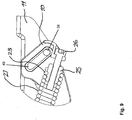
Fig. 2 is a schematic perspective view of a chair tilt mechanism according to an embodiment. -
Fig. 3 is a schematic cross-sectional side view of the chair tilt mechanism ofFig. 2 in a full-tilted position. -
Fig. 4 is a schematic partial perspective view of the chair tilt mechanism ofFig. 2 in a partially tilted position. -
Fig. 5 is a schematic cross-sectional side view of the chair tilt mechanism ofFig. 2 in a zero tilt position. -
Fig. 6 is a schematic partial perspective view of the chair tilt mechanism ofFig. 2 in a zero tilt position. -
Fig. 7 is a further schematic cross-sectional side view of the chair tilt mechanism of -
Fig. 2 in a zero tilt position. -
Fig. 8 is a schematic cross-sectional side view of the chair tilt mechanism ofFig. 2 in a full tilted position. -
Fig. 9 is a schematic partial cross-sectional side view of the chair tilt mechanism of -
Fig. 2 showing an adjustment mechanism in more detail. -
Fig. 10 is a schematic partial perspective view of the chair tilt mechanism ofFig. 2 in a partially tilted position. -
Fig. 11 is a further schematic partial perspective view of the chair tilt mechanism of -
Fig. 2 in a zero tilt position. -
Fig. 12 is a further schematic cross-sectional side view of the chair tilt mechanism of -
Fig. 2 showing a locking mechanism in more detail. -
Fig. 13 is yet a further schematic cross-sectional side view of the chair tilt mechanism ofFig. 2 showing the locking mechanism in more detail. -
Fig. 14 is a schematic partial perspective view of the chair tilt mechanism ofFig. 2 showing the locking mechanism in more detail. -
Fig. 15 is a further schematic cross-sectional side view of the chair tilt mechanism of -
Fig. 2 showing some more details of the locking mechanism. - Exemplary embodiments of the invention will be described with reference to the drawings. While some embodiments will be described in the context of specific fields of application, such as in the context of an office type chair, the embodiments are not limited to this field of application. The features of the various embodiments may be combined with each other unless specifically noted otherwise. Same reference signs in the various drawings refer to similar or identical components.
-
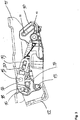
Fig. 1 shows a chair 101 which includes atilt mechanism 100 of an embodiment. The chair 101 is illustrated to be an office-type chair having achair base assembly 102 and a superstructure. The superstructure includes achair seat 103, a chair back 104 and components to interconnect theseat 103 with theback 104. The components which will be described in more detail below, include atilt mechanism 100 for effecting a coordinated motion of the back 104 and theseat 103. Thebase assembly 102 includes apedestal column 107, a number of support legs 105 extending radially from thecolumn 107 and a corresponding number of casters 106 supported on the outer ends of the support legs 105. Additionally, a gas cylinder 108 or other lifting mechanism may be supported by thecolumn 107 to enable the height of theseat 103, and thus of the chair superstructure, to be adjusted by an occupant. - It is to be understood that the terms "forward", "rearward" and "lateral", as used herein, each have a particular meaning that is defined in relation to a flat support surface beneath the chair 101 (for example parallel to a floor on which the casters 106 rest) and in relation to an occupant of the chair. For example, the term "forward" refers to a direction moving away from the back 104 and in front of a chair occupant along an axis which extends parallel to such a flat support surface, while the term "rearward" refers to a direction opposite to the forward direction. The term "lateral" refers to a generally horizontal direction perpendicular to both the forward and rearward direction and extending parallel to the aforementioned flat support surface. The tilt mechanism also defines a rearward direction, to which the second support extends, and an opposing forward direction. The attachment between a base of the
tilt mechanism 100 and thechair base assembly 102 also defines which plane of the tilt mechanism will be oriented horizontally in the installed date of the tilt mechanism. The chair 101 includes thetilt mechanism 100. Generally, thetilt mechanism 100 is operated to implement a coordinated motion of theseat 103 and the back 104 when the back 104 is tilted. Thetilt mechanism 100 includes a base 10 which, in the installed state of thetilt mechanism 100 in which thetilt mechanism 100 is incorporated into the chair 101 as illustrated inFig. 1 , is coupled to thepedestal column 107 via the lifting mechanism 108. Thetilt mechanism 100 includes aseat support 11 which, in the installed state of thetilt mechanism 100, is directly coupled to theseat 103 and supports theseat 103 at a lower side thereof. Theseat support 11 acts as first support which is connected to thebase 10. Theseat support 11 may be mounted to the base 10 such that it is displaceable with respect to thebase 10. Theseat 103 may be fixedly coupled to theseat support 11, such that a translational or rotational motion of theseat support 11 causes theseat 103 to move jointly with theseat support 11 in a translational or rotational manner. Thetilt mechanism 100 includes aback support 12 which, in the installed state of thetilt mechanism 100, is coupled to theback 104. The back 104 may be attached to theback support 12 using suitable connecting members, such as abar 109 fixed to theback support 12. Thebar 109 may be directly and rigidly attached to theback support 12. Theback support 12 acts as a second support. - As will be described in more detail with reference to
Figs. 2 to 15 , thetilt mechanism 100 is configured such that theback support 12 is pivotably coupled to thebase 10, allowing theback support 12 to pivot relatively to thebase 10. Thetilt mechanism 100 has a coupling mechanism coupling both theseat support 11 and theback support 12 to thebase 10. The coupling mechanism includes a link element pivotably coupled to theback support 12, a first guide slot provided at thebase 10, a second guide slot provided at the link element, and a shaft attached to theseat support 11 can slide whilst being supported in the first guide slot and the second guide slot. - When the back 104 is tilted, the link element is moved in the rearward direction which drives the shaft along the second guide slot via a shear action. As the shaft is supported by the first and second guide slots, the shaft simultaneously moves along the first guide slot thus driving the
seat support 11. When the back 104 is tilted, theseat support 11 is thereby displaced relative to thebase 10 and, thus, relative to thechair base assembly 102. - As used herein, the term "guide slot" refers to a slot which may be formed as a cutout, which means a through slot, or as a blind slot. The guide slots described herein may be linear guide slots, which means that the slots are extending in an essentially straight manner. The linear guide slot has a linear centre axis extending linearly from one end of the slot to the opposite end of the slot along the slot longitudinal axis.
-
Figs. 2 and3 show a perspective view and side view, respectively, of thetilt mechanism 100. Thetilt mechanism 100 comprises abase 10, which may be coupled to the gas cylinder 108, a first support (seat support) 11 configured to support thechair seat 103 and connected to thebase 10, a second support (back support) 12 configured to support the chair back 104 and pivotably coupled to the base 10 about afirst pivot axis 13, alink element 14 pivotably coupled to thesecond support 12 about asecond pivot axis 15, and ashaft 16 attached to thefirst support 11. Afirst guide slot 17 is provided at thebase 10 and asecond guide slot 18 is provided at thelink element 14. Theshaft 16 can slide whilst being supported in thefirst guide slot 17 and thesecond guide slot 18 such that pivoting thesecond support 12 relative to the base 10 causes thelink element 14 to be moved in the rearward direction, which causes theshaft 16 to be displaced along thefirst guide slot 17 and thesecond guide slot 18. - The
link element 14 may comprise an individual element which is not part of thefirst support 11, thesecond support 12 or thebase 10. Thelink element 14 may be rotatable with respect to thesecond support 12 about thesecond pivot axis 15. Further, thelink element 14 may be rotatable and displaceable in the front-rear and up-down directions with respect to thefirst support 11 and thebase 10. - The
tilt mechanism 100 may have a compact and simple construction, with the coupling between thefirst support 11 and thesecond support 12 implemented in a structure disposed below the chair seat. Thetilt mechanism 100 may provide self-weighing characteristics. - The
tilt mechanism 100 may include a biasing mechanism to bias thetilt mechanism 100 into a position in which theback 104 is in its foremost position. The biasing mechanism may be implemented by aspring 21, for example a tension spring or a compression spring. - The base 10 generally has a U-shaped cross section in a plane extending in the lateral direction of the
tilt mechanism 100. Thebase 10 has a bottom wall, which may be coupled to thechair base assembly 102. From the bottom of the base 10 to side walls may extend in an upward and forward-backward direction of thetilt mechanism 100. Within this U-shaped cross section of thebase 10, thelink element 14 and thespring 21 as well as further components for controlling the tilt mechanism may be accommodated. - The first support (seat support) 11 may comprise two L-shaped profiles laterally spaced apart, wherein one leg of each of the L-shaped profiles may be coupled to the
chair seat 103 and the other leg of each of the L-shaped profiles is indirectly mounted to thebase 10 and displaceable with respect to thebase 10. However, although not shown in the figures, thefirst support 11 may comprise a single element, for example, the first support may comprise a U shaped profile with a central section coupled to thechair seat 103 and side walls extending downwards and mounted indirectly to the base 10 like the legs of the L-shaped profiles. The side walls may be connected to the base 10 such that they are displaceable with respect to thebase 10. - The second support (back support) 12 may have a U-shaped cross section forming a
central section 27, afirst arm 28 and a second arm 29 (see for exampleFig. 10 ). Thecentral section 27 may be coupled to the chair back 104. The first andsecond arms first pivot axis 13, for example via a pin extending along thefirst pivot axis 13 or via corresponding pivot bearings at each side wall of thebase 10. - The
link element 14 is accommodated between the sidewalls of thebase 10. Thelink element 14 is pivotably coupled to thesecond support 12 about thesecond pivot axis 15, for example via a pin extending from thefirst arm 28 to thesecond arm 29 through a matching opening in thelink element 14. Thefirst pivot axis 13 and thesecond pivot axis 15 are arranged in parallel and spaced apart from each other. Thus, thelink element 14 is at least partially positively driven by a movement or rotation of thesecond support 12 when the chair back 104 is tilted. - The
first guide slot 17 is provided at each of the sidewalls of thebase 10. In the sectional side view shown inFig. 3 , a side view of one of the sidewalls of thebase 10 is shown with the correspondingfirst guide slot 17. Thefirst guide slot 17 may comprise a linear guide slot. In the link element 14 asecond guide slot 18 is provided. Thesecond guide slot 18 may also comprise a linear guide slot. Ashaft 16 is attached to thefirst support 11 and extends through thefirst guide slot 17 of one side wall of thebase 10, next through thesecond guide slot 18 of thelink element 14 and further through thefirst guide slot 17 of the other side wall of thebase 10. Both ends of theshaft 16 may be mounted at thefirst support 11. As indicated inFig. 3 , a longitudinal direction of thefirst guide slot 17 and a longitudinal direction of thesecond guide slot 18 are not parallel, but arranged angular, such that a positively driven arrangement of thefirst guide slot 17, thesecond guide slot 18 and theshaft 16 may be achieved. As theshaft 16 is mounted at the rearward end of thefirst support 11, the rearward end of thefirst support 11 is also positively driven by the arrangement of thelink element 14, thebase 10 and theshaft 16. As thelink element 14 is coupled to thesecond support 12 and driven by tilting thesecond support 12, a coordinated movement between the tilting of thesecond support 12 and a movement of thefirst support 11 can be achieved. At the forward end of thefirst support 11, afurther shaft 39 may be provided extending in parallel to theshaft 16. Furthermore, athird guide slot 40 may be provided at each of the sidewalls of the base 10 in a front area of the base 10 such that thefurther shaft 39 is extending through thethird guide slots 40 and positively drives the front end of thefirst support 11. Thefirst guide slot 17 and thethird guide slot 40 may have a different angle of inclination with respect to the bottom wall of thebase 10. Therefore, when thefirst support 11 is moved driven byshaft 16 in the front-and rear direction, a change of the height of the front side of thefirst support 11 is different compared to a change of the height of the rear side of thefirst support 11. Thus, thefirst support 11 and consequently thechair seat 103 may not only be moved in the front-rear direction, but also tilted when the chair back 104 is tilted. - At the
base 10, afurther shaft 19 may be provided which extends in parallel to theshaft 16. Afourth guide slot 20 may be provided in thelink element 14 through which thefurther shaft 19 is extending. Thefurther shaft 19 in combination with thefourth guide slot 20 provides a coordinated movement of thelink element 14, when thelink element 14 is driven via thesecond pivot axis 15 when thesecond support 12 is tilted. -
Fig. 2 shows furthermore ahandle 41 which may be operated by an occupant and which may actuate a locking mechanism of thetilt mechanism 100. The locking mechanism locks and unlocks the coordinated movement of thefirst support 11 and thesecond support 12. In a locked state of the locking mechanism, thefirst support 11 and thesecond support 12 are maintained in a fixed position with respect to thebase 10. In an unlocked state of the locking mechanism, thefirst support 11 and thesecond support 12 may be moved in a coordinated manner with respect to thebase 10. Details on the locking mechanism will be described in connection withFigs. 10 to 15 . -
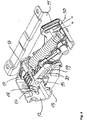
Fig. 4 shows a schematic perspective partial sectional view of thetilt mechanism 100. In particular,Fig. 4 shows the arrangement of thelink element 14 accommodated between the sidewalls of thebase 10 and between the arms of the U-shapedsecond support 12. - In the following, the coordinated movement between the
first support 11 and thesecond support 12 will be described in more detail. Thetilt mechanism 100 may enable to move the chair back 104 between a zero tilt and a full tilt position. In the zero tilt position, the chair back may be arranged in an essentially perpendicular direction with respect to the surface on which the chair 101 is provided. Consequently, the central section of the U shapedsecond support 12 may be arranged in the zero tilt position in an essentially perpendicular direction with respect to the surface on which the chair 101 is provided. In the full tilt position, the chair back 101 as well as the central section of the U-shapedsecond support 12 may be inclined in an angle from about 30° to about 50° from the zero tilt position. The full tilt position as well as the zero tilt position may be limited by thetilt mechanism 100. In the following, a position between the full tilt position and the zero tilt position will be called partially tilt position. -
Fig. 5 shows a sectional side view of thetilt mechanism 100 in the zero tilt position. Theshaft 39 is located at the lowest and furthest forward position in thethird guide slot 40. Theshaft 16 is arranged at the uppermost position of thesecond guide slot 18 and at the furthest forward position of thefirst guide slot 17. Theshaft 19 is arranged at the rearmost position of thefourth guide slot 20. -
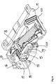
Fig. 6 shows a perspective sectional view of thetilt mechanism 100 in this zero tilt position. -
Fig. 7 shows a further sectional side view of thetilt mechanism 100 in this zero tilt position. In particular,Fig. 7 shows the arrangement of thespring 21 in this zero tilt position. Thespring 21 has afirst end 22 and asecond end 23. Thespring 21 may comprise a source of stored energy such that it may provide a restoring force when the distance between thefirst end 22 and thesecond end 23 is enlarged. Thefirst end 22 is coupled to a corresponding firstspring attachment structure 24 at thelink element 14. Thesecond end 23 of thespring 21 is coupled to a secondspring attachment structure 25 at thebase 10. -
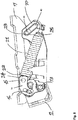
Fig. 8 shows the sectional side view of thetilt mechanism 100 ofFig. 7 in the full tilt position. Thesecond support 12 is inclined into a backward direction by rotating about thefirst pivot axis 13 with respect to thebase 10. Due to the rotating movement of thesecond support 12, thesecond pivot axis 15 is moved in a backward direction. Together with thepivot axis 15, thelink element 14 is also moved in a backward direction urging theshaft 16 backwards. As theshaft 16 is coupled to thefirst support 11, thefirst support 11 is also moved backwards. Further, as theshaft 16 is also guided by thefirst guide slot 17 in thebase 10, theshaft 16 is moved together with the rear part of thefirst support 11 in an upward direction. Theshaft 39 is moved together with thefirst support 11 in a rearward and upward direction guided in thethird guide slot 40. Thus, thefirst support 11 is moved as a whole together with thechair seat 103 in an upward and rearward direction and is tilted at the same time. - The chair back 104 and thus the
second support 12 may be inclined from the zero tilt position in the full tilt position or in any partially tilt position between the zero tilt position and the full tilt position by an occupant sitting on thechair seat 103 and leaning back against the chair back 104. When thelink element 14 is moved in the rearward direction, thespring 21 is enlarged and tensioned. Thus, thespring 21 provides a restoring force urging thetilt mechanism 100 back in the zero tilt position when the occupant does not apply a back-leaning force to the chair back 104. -
Fig. 9 shows the secondspring attachment structure 25 at the base 10 in more detail. The secondspring attachment structure 25 may comprise anadjustment element 26, for example a screw, for adjusting a pre-tension of thespring 21. Thus, the restoring force of thespring 21 may be adjusted. - The
tilt mechanism 100 may comprise a locking mechanism for mechanically locking the tilt mechanism in certain positions, for example in the full tilt position, in the zero tilt position and in at least some partially tilted positions. As shown inFigs. 10 to 15 , the locking mechanism may comprise amale lock plate 32, a female engageplate 33, aspring element 37, and acoupling element 38. The female engageplate 33 is mounted at thesecond support 12. Thus, the female engageplate 33 is moving together with thesecond support 12. The female engageplate 33 comprises a plurality of recesses into which themale lock plate 32 may engage. Themale lock plate 32 is arranged in a guidance which is mounted at thebase 10. Themale lock plate 32 can slide in the forward and backward direction between a front position and a rear position. In the front position, themale lock plate 32 is disengaged from the female engageplate 33 such that thesecond support 12 can be freely moved and rotated around thefirst pivot axis 13. In the rear position, themale lock plate 32 is engaged with one of the recesses at the female engageplate 33. Therefore, in the rear position of themale lock plate 32, thesecond support 12 cannot rotate about thefirst pivot axis 13. Thus, in the front position of themale lock plate 32, thetilt mechanism 100 is in the unlocked state and can be freely adjusted, whereas in the rear position of themale lock plate 32, thetilt mechanism 100 is in the locked state and thesecond support 12 is locked in a certain position. -
Figs. 10 and12 show the locked state of thetilt mechanism 100 in a partially tilted position in a perspective view and the side view, respectively. -
Figs. 11 and13 show the locked state of thetilt mechanism 100 in the zero tilt position in a perspective view and a side view, respectively. - The
male lock plate 32 may be operated by the occupant with thehandle 41. Thehandle 41 may be rotated around its longitudinal direction. For example, thehandle 41 may be rotated in a clockwise direction for unlocking thetilt mechanism 100, and thehandle 41 may be rotated in a counter-clockwise direction for locking thetilt mechanism 100. -
Figs. 14 and15 show the elements for controlling the locking mechanism in more detail. Thespring element 37 may be coupled to thehandle 41 at a proximal end of thespring element 37 via acontrol element 35. The distal end of thespring element 37 may be engaged with thecoupling element 38, which is coupled with themale lock plate 32. - When the
handle 41 is rotated in the clockwise direction, the distal end of thespring element 37 urges thecoupling element 38 together with themale lock plate 32 in the forward direction, thus unlocking thetilt mechanism 100. - When the
handle 41 is rotated in the counter-clockwise direction, the distal end of thespring element 37 urges thecoupling element 38 together with themale lock plate 32 in the rearward direction. When themale lock plate 32 is facing one of the recesses of the female engageplate 33, thespring element 37 moves themale lock plate 32 into this recess of the female engageplate 33. However, when themale lock plate 32 does not face one of the recesses of the female engageplate 33, the spring element urges themale lock plate 32 against one of the teeth between the recesses of the female engageplate 33. Thesecond support 12 is still moveable. However, when thesecond support 12 is moved, themale lock plate 32 will engage with one of the recesses of the female engageplate 33 as soon as possible, thus locking thetilt mechanism 100. - As further shown in figure
Fig. 15 , adetent element 36 may be provided at thehandle 41 or thecontrol element 35 for locking thehandle 41 in the locking and unlocking position. - In particular
Figs. 10 and11 show the arrangement of the locking mechanism in parallel to thespring 21 at thesecond support 12 and thelink element 14, respectively. Thesecond pivot axis 15 has afirst end 31 and asecond end 30. Thespring 21 is mounted at thelink element 14 near thefirst end 31, whereas the locking mechanism is arranged at the opposite side near the second and 30. This allows a compact design of thetilt mechanism 100. - While the
tilt mechanism 100 has been described withlinear guide slots guide slots - Furthermore, the
tilt mechanism 100 may comprise further components, for example two or more springs instead of thesingle spring 21, and a handle and a mechanism for the gas cylinder 108. - While exemplary embodiments have been described in the context of office-type chairs, the
tilt mechanism 100 and the chair 101 according to embodiments of the invention are not limited to this particular application. Rather, embodiments of the invention may be employed to effect a coordinated motion of a chair back and the chair seat in a wide variety of chairs.
Claims (14)
- A tilt mechanism for a chair, configured to affect a coordinated movement of a chair seat (103) and chair back (104), the tilt mechanism comprising (100):- a base (10),- a first support (11) configured to support the chair seat (103) and mounted to the base (10),- a second support (12) configured to support the chair back (104) and pivotably coupled to the base (10) about a first pivot axis (13),- a link element (14) pivotably coupled to the second support (12) about a second pivot axis (15),- a shaft (16) attached to the first support (11),wherein a first guide slot (17) is provided at the base (10) and a second guide slot (18) is provided at the link element (14), wherein the shaft (16) is supported in the first guide slot (17) and the second guide slot (18) such that pivoting the second support (12) relative to the base (10) causes the shaft (16) to be displaced along the first and second guide slots (17, 18), and- an energy storage mechanism (21) including a first end (22) and a second end (23), the first end (22) being coupled to a first attachment structure (24) provided at the link element (14) and the second end (21) being coupled to a second attachment structure (25) provided at the base (10), wherein an energy level stored in the energy storage mechanism (21) depends on a distance between the first end and the second end (22, 23),characterized in that
the first attachment structure (24) is provided at the second pivot axis (15). - The tilt mechanism according to claim 1, wherein a longitudinal direction of the shaft (16) is parallel to the first pivot axis (13).
- The tilt mechanism according to claim 1 or claim 2, wherein the second pivot axis (15) is different from the first pivot axis (13).
- The tilt mechanism according to any one of the preceding claims, wherein the first pivot axis (13) is parallel to the second pivot axis (15).
- The tilt mechanism according to any one of the preceding claims, wherein the first guide slot (17) comprises a first linear guide slot and the second guide slot (18) comprises a second linear guide slot.
- The tilt mechanism according to claim 5, wherein the first linear guide slot (17) and the second linear guide slot (18) are arranged nonparallel such that, when the shaft (16) is displaced along the first and second linear guide slots (17, 18), an angle between a direction of the first linear guide slot (17) and a direction of the second linear guide slot (18) varies.
- The tilt mechanism according to any one of the preceding claims, wherein the tilt mechanism is configured such that a distance between the first attachment structure (24) and the second attachment structure (25) varies upon pivoting the second support (12) relative to the base (10).
- The tilt mechanism according to any one of the preceding claims, wherein the energy storage mechanism (21) comprises a single tension spring.
- The tilt mechanism according to any one of the preceding claims, wherein the second support (12) comprises a U-shaped section forming a central section (27), a first arm (28) and a second arm (29), wherein a pin extends along the second pivot axis (15) from the first arm (28) to the second arm (29) through an opening in the link element (14), wherein the pin includes a first end (31) and a second end (30) in its longitudinal direction, wherein the first attachment structure (24) is arranged closer to the first end (31) of the pin than to the second end (30) of the pin.
- The tilt mechanism according to claim 9, comprising a locking mechanism (32) mounted at the base (10) and configured to engage with a locking section (33) provided at the link element (14) for inhibiting a movement of the link element (14) upon actuating the locking mechanism (32).
- The tilt mechanism according to claim 10, wherein the locking section (33) is arranged closer to the second end (30) of the pin than to the first end (31) of the pin.
- The tilt mechanism according to any one of the preceding claims, further comprising a further shaft (39) attached to the first support (11) and supported in a third guide slot (40) provided at the base (10).
- The tilt mechanism according to claim 12, wherein a longitudinal direction of the further shaft (39) is parallel to a longitudinal direction of the shaft (16).
- A chair, comprising
a chair base assembly (102),
a chair seat (103),
a chair back (104), and
a tilt mechanism (100) according to any one of the preceding claims, the base (10) of the tilt mechanism (100) being attached to the chair base assembly (102), the chair seat (103) being attached to the first support (11) of the tilt mechanism (100), and the chair back (104) being attached to the second support (12) of the tilt mechanism (100).
Priority Applications (7)
| Application Number | Priority Date | Filing Date | Title |
|---|---|---|---|
| ES18167704T ES2800425T3 (en) | 2018-04-17 | 2018-04-17 | Tilt mechanism of a chair and chair |
| PL18167704T PL3556252T3 (en) | 2018-04-17 | 2018-04-17 | Tilt mechanism for a chair and chair |
| EP18167704.8A EP3556252B1 (en) | 2018-04-17 | 2018-04-17 | Tilt mechanism for a chair and chair |
| CA3095867A CA3095867C (en) | 2018-04-17 | 2019-04-04 | Tilt mechanism for a chair and chair |
| CN201980026330.9A CN111989013A (en) | 2018-04-17 | 2019-04-04 | Reclining mechanism for chair and chair |
| PCT/EP2019/058472 WO2019201608A1 (en) | 2018-04-17 | 2019-04-04 | Tilt mechanism for a chair and chair |
| US17/048,175 US11350750B2 (en) | 2018-04-17 | 2019-04-04 | Tilt mechanism for a chair and chair |
Applications Claiming Priority (1)
| Application Number | Priority Date | Filing Date | Title |
|---|---|---|---|
| EP18167704.8A EP3556252B1 (en) | 2018-04-17 | 2018-04-17 | Tilt mechanism for a chair and chair |
Publications (2)
| Publication Number | Publication Date |
|---|---|
| EP3556252A1 EP3556252A1 (en) | 2019-10-23 |
| EP3556252B1 true EP3556252B1 (en) | 2020-05-13 |
Family
ID=62017206
Family Applications (1)
| Application Number | Title | Priority Date | Filing Date |
|---|---|---|---|
| EP18167704.8A Active EP3556252B1 (en) | 2018-04-17 | 2018-04-17 | Tilt mechanism for a chair and chair |
Country Status (7)
| Country | Link |
|---|---|
| US (1) | US11350750B2 (en) |
| EP (1) | EP3556252B1 (en) |
| CN (1) | CN111989013A (en) |
| CA (1) | CA3095867C (en) |
| ES (1) | ES2800425T3 (en) |
| PL (1) | PL3556252T3 (en) |
| WO (1) | WO2019201608A1 (en) |
Families Citing this family (5)
| Publication number | Priority date | Publication date | Assignee | Title |
|---|---|---|---|---|
| NO343925B1 (en) * | 2017-10-20 | 2019-07-08 | Ekornes Asa | Sit Module |
| JPWO2020255195A1 (en) * | 2019-06-17 | 2020-12-24 | ||
| US11957246B2 (en) * | 2020-07-22 | 2024-04-16 | Formway Furniture Limited | Chair |
| USD970912S1 (en) | 2020-12-18 | 2022-11-29 | MillerKnoll, Inc. | Chair |
| CN116172355B (en) * | 2023-02-21 | 2023-12-01 | 赛动(安吉)家具股份有限公司 | Chair back mechanism and electronic competition chair |
Family Cites Families (49)
| Publication number | Priority date | Publication date | Assignee | Title |
|---|---|---|---|---|
| EP0198056B1 (en) * | 1984-10-25 | 1991-01-09 | Konrad Neumüller | Seat support for chairs, especially for rotating work-chairs |
| DE8515221U1 (en) * | 1985-05-23 | 1986-05-22 | VOKO - Franz Vogt & Co, 6301 Pohlheim | Seating |
| DE3622272A1 (en) * | 1986-07-03 | 1988-01-21 | Porsche Ag | CHAIR, ESPECIALLY OFFICE CHAIR |
| IT1236439B (en) * | 1989-12-14 | 1993-03-01 | Loris Miotto | Movement device for chair |
| DK0461228T3 (en) | 1989-12-29 | 1994-12-19 | Wilkhahn Wilkening & Hahne | Synchronous setting device for office chairs and the like |
| DE9109184U1 (en) * | 1991-07-25 | 1991-10-10 | Sifa Sitzfabrik Gmbh, 8458 Sulzbach-Rosenberg, De | |
| DE9112861U1 (en) * | 1991-10-16 | 1992-01-02 | Sifa Sitzfabrik Gmbh, 8458 Sulzbach-Rosenberg, De | |
| IL103477A0 (en) * | 1992-10-20 | 1993-03-15 | Paltechnica Nitzanim | Office and like chairs |
| US5582459A (en) * | 1993-09-30 | 1996-12-10 | Itoki Crebio Corporation | Chair having tiltable seat back |
| US5871258A (en) | 1997-10-24 | 1999-02-16 | Steelcase Inc. | Chair with novel seat construction |
| US6250715B1 (en) * | 1998-01-21 | 2001-06-26 | Herman Miller, Inc. | Chair |
| IT1305620B1 (en) | 1998-05-05 | 2001-05-09 | Cofemo Spa | SYNCHRONISM ADJUSTMENT DEVICE OF THE SEAT SET UP OF A CHAIR |
| US6131998A (en) * | 1999-11-22 | 2000-10-17 | Su; Tung-Hua | Chassis for a chair seat |
| DE10122945A1 (en) | 2001-05-11 | 2002-12-12 | Armin Sander | Chair, especially office chair |
| DE10123316A1 (en) * | 2001-05-14 | 2002-11-28 | Johannes Uhlenbrock | Chair, especially office chair, with adjustable backrest preload |
| US20030132653A1 (en) | 2001-10-18 | 2003-07-17 | Doug Thole | Tension control mechanism for a chair |
| US6945602B2 (en) | 2003-12-18 | 2005-09-20 | Haworth, Inc. | Tilt control mechanism for chair |
| DE102004007095A1 (en) | 2004-02-13 | 2005-08-25 | Interstuhl Büromöbel GmbH & Co. KG | Office chair is mounted on support with curved upper surface, pneumatic spring moving support to reclining position and pneumatic lines connecting spring to cylinders which move slides attached to back rest |
| ITMI20050116U1 (en) | 2005-04-06 | 2006-10-07 | Donati Spa | SYNCHRONIZATION MECHANISM FOR CHAIRS OR ARMCHAIRS |
| DE202005011725U1 (en) | 2005-07-27 | 2006-12-07 | Sander, Armin | Chair, especially office chair |
| DE102007021782B3 (en) | 2007-05-07 | 2008-09-18 | Bock 1 Gmbh & Co. Kg | Synchronous mechanism for office chairs |
| ITTO20070398A1 (en) | 2007-06-06 | 2008-12-07 | Malenotti S R L | "CHAIR WITH OSCILLATING BACKREST" |
| CN201175121Y (en) * | 2008-03-05 | 2009-01-07 | 富翔股份有限公司 | Chair-back leaning-facing upward interlock seat-part |
| TW200950726A (en) * | 2008-06-06 | 2009-12-16 | Fon Chin Ind Co Ltd | Front-and-back reciprocating, reclining, lifting and lowering apparatus for a chair back |
| IT1395300B1 (en) | 2008-10-22 | 2012-09-05 | Imarc Spa | ADJUSTMENT SYSTEM OF THE MUTUAL POSITION AMONG TWO FURNITURE PARTS.- |
| US8973995B2 (en) | 2009-02-25 | 2015-03-10 | Donati S.P.A. | Device for synchronizing the tilt of a chair back and seat |
| WO2010103554A1 (en) * | 2009-03-10 | 2010-09-16 | Effe Tre S.R.L. | Support device of a chair with tilting backrest |
| EP2477523B1 (en) | 2009-09-15 | 2013-06-05 | Bock 1 GmbH & Co. KG | Tilting mechanism for an office chair |
| US8613482B2 (en) | 2010-02-08 | 2013-12-24 | Hangzhou Zhongtai Industrial Co., Ltd. | Chair chassis |
| BR112012021407B1 (en) | 2010-02-26 | 2020-06-09 | Donati Spa | device to synchronize the inclination of the backrest and seat of a chair |
| TW201141422A (en) | 2010-05-31 | 2011-12-01 | Wen-Shan Ke | Chair adjustment device |
| CN201743286U (en) | 2010-07-20 | 2011-02-16 | 杭州中泰实业有限公司 | Adjustable revolving chair tray of rolling shaft |
| CA2808205C (en) * | 2010-08-25 | 2015-10-13 | L&P Property Management Company | Tilt mechanism for a chair and chair |
| EP2608700B1 (en) * | 2010-08-25 | 2014-07-02 | L&P Property Management Company | Tilt mechanism for a chair and chair |
| GB201015414D0 (en) * | 2010-09-15 | 2010-10-27 | Birkbeck Hilary R | Link chair action |
| DE102010046994B4 (en) | 2010-09-30 | 2023-01-12 | Bock 1 Gmbh & Co. Kg | synchronous mechanism |
| DE102011010099A1 (en) | 2011-02-01 | 2012-08-02 | Bock 1 Gmbh & Co. Kg | synchronous mechanism |
| CA2837363C (en) * | 2011-07-01 | 2016-06-14 | L&P Property Management Company | Tilt mechanism for a chair and chair |
| DE102011051966B8 (en) | 2011-07-20 | 2013-06-13 | Interstuhl Büromöbel GmbH & Co. KG | chair |
| PL2772156T3 (en) * | 2013-02-27 | 2020-09-21 | L&P Property Management Company | Tilt mechanism for a chair and chair |
| CN203378783U (en) | 2013-03-18 | 2014-01-08 | 佛山高飞模家具配件有限公司 | Self-weight base plate for pushing seat part through back part of chair |
| JP6215659B2 (en) * | 2013-11-12 | 2017-10-18 | コクヨ株式会社 | Chair |
| EP2886015B1 (en) | 2013-12-17 | 2016-07-13 | Donati S.p.A. | Chair with adjustable backrest |
| CN106413479A (en) | 2014-03-28 | 2017-02-15 | 多纳蒂股份公司 | Device for synchronizing tilt of the backrest and seat of chair |
| DE102014104870A1 (en) | 2014-04-04 | 2015-10-08 | Bock 1 Gmbh & Co. Kg | Mechanics for an office chair |
| DE102014226645B4 (en) | 2014-12-19 | 2023-10-05 | Hangzhou Zhongtai Industrial Group Co., Ltd. | Adjustment mechanism for adjusting a restoring force acting on a backrest of a chair and office chair with such an adjustment mechanism |
| DE102015101545A1 (en) | 2015-02-03 | 2016-08-04 | Bock 1 Gmbh & Co. Kg | synchronous mechanism |
| DE102015111946A1 (en) | 2015-07-22 | 2017-01-26 | Bock 1 Gmbh & Co. Kg | Mechanics for an office chair |
| IT201700112144A1 (en) * | 2017-10-06 | 2019-04-06 | Co Fe Mo Ind S R L | OSCILLATION SYSTEM FOR CHAIRS |
-
2018
- 2018-04-17 ES ES18167704T patent/ES2800425T3/en active Active
- 2018-04-17 PL PL18167704T patent/PL3556252T3/en unknown
- 2018-04-17 EP EP18167704.8A patent/EP3556252B1/en active Active
-
2019
- 2019-04-04 WO PCT/EP2019/058472 patent/WO2019201608A1/en active Application Filing
- 2019-04-04 CA CA3095867A patent/CA3095867C/en active Active
- 2019-04-04 CN CN201980026330.9A patent/CN111989013A/en active Pending
- 2019-04-04 US US17/048,175 patent/US11350750B2/en active Active
Non-Patent Citations (1)
| Title |
|---|
| None * |
Also Published As
| Publication number | Publication date |
|---|---|
| CA3095867A1 (en) | 2019-10-24 |
| US20210368982A1 (en) | 2021-12-02 |
| CA3095867C (en) | 2022-12-13 |
| CN111989013A (en) | 2020-11-24 |
| ES2800425T3 (en) | 2020-12-30 |
| EP3556252A1 (en) | 2019-10-23 |
| US11350750B2 (en) | 2022-06-07 |
| PL3556252T3 (en) | 2020-11-16 |
| WO2019201608A1 (en) | 2019-10-24 |
Similar Documents
| Publication | Publication Date | Title |
|---|---|---|
| EP3556252B1 (en) | Tilt mechanism for a chair and chair | |
| US10455940B2 (en) | Chair and chair control assemblies, systems, and methods | |
| US7997652B2 (en) | Tilt control mechanism for a chair | |
| EP0614633B1 (en) | Adjustbale backrest for a chair | |
| US7066538B2 (en) | Chair with tilt lock mechanism | |
| EP3709840B1 (en) | Chair tilt mechanism | |
| EP2772156B1 (en) | Tilt mechanism for a chair and chair | |
| EP2608700B1 (en) | Tilt mechanism for a chair and chair | |
| US20100156158A1 (en) | Lumbar support system for furniture member | |
| US20060284461A1 (en) | Chair with recline control mechanism, recline limit control and back tilt mechanism | |
| EP4335324A1 (en) | Tilt mechanism for a chair | |
| US11812853B2 (en) | Tilt locking device | |
| EP4108135A1 (en) | Motion mechanism for a chair and chair | |
| JP2021100456A (en) | Back rest locking range adjustment mechanism and chair | |
| CA2848646A1 (en) | Tilt control mechanism for a chair |
Legal Events
| Date | Code | Title | Description |
|---|---|---|---|
| STAA | Information on the status of an ep patent application or granted ep patent |
Free format text: STATUS: EXAMINATION IS IN PROGRESS |
|
| PUAI | Public reference made under article 153(3) epc to a published international application that has entered the european phase |
Free format text: ORIGINAL CODE: 0009012 |
|
| 17P | Request for examination filed |
Effective date: 20181012 |
|
| AK | Designated contracting states |
Kind code of ref document: A1 Designated state(s): AL AT BE BG CH CY CZ DE DK EE ES FI FR GB GR HR HU IE IS IT LI LT LU LV MC MK MT NL NO PL PT RO RS SE SI SK SM TR |
|
| AX | Request for extension of the european patent |
Extension state: BA ME |
|
| GRAP | Despatch of communication of intention to grant a patent |
Free format text: ORIGINAL CODE: EPIDOSNIGR1 |
|
| STAA | Information on the status of an ep patent application or granted ep patent |
Free format text: STATUS: GRANT OF PATENT IS INTENDED |
|
| INTG | Intention to grant announced |
Effective date: 20191211 |
|
| GRAS | Grant fee paid |
Free format text: ORIGINAL CODE: EPIDOSNIGR3 |
|
| GRAA | (expected) grant |
Free format text: ORIGINAL CODE: 0009210 |
|
| STAA | Information on the status of an ep patent application or granted ep patent |
Free format text: STATUS: THE PATENT HAS BEEN GRANTED |
|
| AK | Designated contracting states |
Kind code of ref document: B1 Designated state(s): AL AT BE BG CH CY CZ DE DK EE ES FI FR GB GR HR HU IE IS IT LI LT LU LV MC MK MT NL NO PL PT RO RS SE SI SK SM TR |
|
| REG | Reference to a national code |
Ref country code: GB Ref legal event code: FG4D |
|
| REG | Reference to a national code |
Ref country code: CH Ref legal event code: EP |
|
| REG | Reference to a national code |
Ref country code: DE Ref legal event code: R096 Ref document number: 602018004375 Country of ref document: DE |
|
| REG | Reference to a national code |
Ref country code: AT Ref legal event code: REF Ref document number: 1269083 Country of ref document: AT Kind code of ref document: T Effective date: 20200615 |
|
| REG | Reference to a national code |
Ref country code: LT Ref legal event code: MG4D |
|
| REG | Reference to a national code |
Ref country code: NL Ref legal event code: MP Effective date: 20200513 |
|
| PG25 | Lapsed in a contracting state [announced via postgrant information from national office to epo] |
Ref country code: PT Free format text: LAPSE BECAUSE OF FAILURE TO SUBMIT A TRANSLATION OF THE DESCRIPTION OR TO PAY THE FEE WITHIN THE PRESCRIBED TIME-LIMIT Effective date: 20200914 Ref country code: IS Free format text: LAPSE BECAUSE OF FAILURE TO SUBMIT A TRANSLATION OF THE DESCRIPTION OR TO PAY THE FEE WITHIN THE PRESCRIBED TIME-LIMIT Effective date: 20200913 Ref country code: FI Free format text: LAPSE BECAUSE OF FAILURE TO SUBMIT A TRANSLATION OF THE DESCRIPTION OR TO PAY THE FEE WITHIN THE PRESCRIBED TIME-LIMIT Effective date: 20200513 Ref country code: GR Free format text: LAPSE BECAUSE OF FAILURE TO SUBMIT A TRANSLATION OF THE DESCRIPTION OR TO PAY THE FEE WITHIN THE PRESCRIBED TIME-LIMIT Effective date: 20200814 Ref country code: NO Free format text: LAPSE BECAUSE OF FAILURE TO SUBMIT A TRANSLATION OF THE DESCRIPTION OR TO PAY THE FEE WITHIN THE PRESCRIBED TIME-LIMIT Effective date: 20200813 Ref country code: SE Free format text: LAPSE BECAUSE OF FAILURE TO SUBMIT A TRANSLATION OF THE DESCRIPTION OR TO PAY THE FEE WITHIN THE PRESCRIBED TIME-LIMIT Effective date: 20200513 Ref country code: LT Free format text: LAPSE BECAUSE OF FAILURE TO SUBMIT A TRANSLATION OF THE DESCRIPTION OR TO PAY THE FEE WITHIN THE PRESCRIBED TIME-LIMIT Effective date: 20200513 |
|
| PG25 | Lapsed in a contracting state [announced via postgrant information from national office to epo] |
Ref country code: BG Free format text: LAPSE BECAUSE OF FAILURE TO SUBMIT A TRANSLATION OF THE DESCRIPTION OR TO PAY THE FEE WITHIN THE PRESCRIBED TIME-LIMIT Effective date: 20200813 Ref country code: RS Free format text: LAPSE BECAUSE OF FAILURE TO SUBMIT A TRANSLATION OF THE DESCRIPTION OR TO PAY THE FEE WITHIN THE PRESCRIBED TIME-LIMIT Effective date: 20200513 Ref country code: LV Free format text: LAPSE BECAUSE OF FAILURE TO SUBMIT A TRANSLATION OF THE DESCRIPTION OR TO PAY THE FEE WITHIN THE PRESCRIBED TIME-LIMIT Effective date: 20200513 Ref country code: HR Free format text: LAPSE BECAUSE OF FAILURE TO SUBMIT A TRANSLATION OF THE DESCRIPTION OR TO PAY THE FEE WITHIN THE PRESCRIBED TIME-LIMIT Effective date: 20200513 |
|
| PG25 | Lapsed in a contracting state [announced via postgrant information from national office to epo] |
Ref country code: AL Free format text: LAPSE BECAUSE OF FAILURE TO SUBMIT A TRANSLATION OF THE DESCRIPTION OR TO PAY THE FEE WITHIN THE PRESCRIBED TIME-LIMIT Effective date: 20200513 Ref country code: NL Free format text: LAPSE BECAUSE OF FAILURE TO SUBMIT A TRANSLATION OF THE DESCRIPTION OR TO PAY THE FEE WITHIN THE PRESCRIBED TIME-LIMIT Effective date: 20200513 |
|
| PG25 | Lapsed in a contracting state [announced via postgrant information from national office to epo] |
Ref country code: DK Free format text: LAPSE BECAUSE OF FAILURE TO SUBMIT A TRANSLATION OF THE DESCRIPTION OR TO PAY THE FEE WITHIN THE PRESCRIBED TIME-LIMIT Effective date: 20200513 Ref country code: SM Free format text: LAPSE BECAUSE OF FAILURE TO SUBMIT A TRANSLATION OF THE DESCRIPTION OR TO PAY THE FEE WITHIN THE PRESCRIBED TIME-LIMIT Effective date: 20200513 Ref country code: EE Free format text: LAPSE BECAUSE OF FAILURE TO SUBMIT A TRANSLATION OF THE DESCRIPTION OR TO PAY THE FEE WITHIN THE PRESCRIBED TIME-LIMIT Effective date: 20200513 Ref country code: CZ Free format text: LAPSE BECAUSE OF FAILURE TO SUBMIT A TRANSLATION OF THE DESCRIPTION OR TO PAY THE FEE WITHIN THE PRESCRIBED TIME-LIMIT Effective date: 20200513 Ref country code: RO Free format text: LAPSE BECAUSE OF FAILURE TO SUBMIT A TRANSLATION OF THE DESCRIPTION OR TO PAY THE FEE WITHIN THE PRESCRIBED TIME-LIMIT Effective date: 20200513 |
|
| REG | Reference to a national code |
Ref country code: DE Ref legal event code: R097 Ref document number: 602018004375 Country of ref document: DE |
|
| PG25 | Lapsed in a contracting state [announced via postgrant information from national office to epo] |
Ref country code: SK Free format text: LAPSE BECAUSE OF FAILURE TO SUBMIT A TRANSLATION OF THE DESCRIPTION OR TO PAY THE FEE WITHIN THE PRESCRIBED TIME-LIMIT Effective date: 20200513 |
|
| PLBE | No opposition filed within time limit |
Free format text: ORIGINAL CODE: 0009261 |
|
| STAA | Information on the status of an ep patent application or granted ep patent |
Free format text: STATUS: NO OPPOSITION FILED WITHIN TIME LIMIT |
|
| 26N | No opposition filed |
Effective date: 20210216 |
|
| PG25 | Lapsed in a contracting state [announced via postgrant information from national office to epo] |
Ref country code: MC Free format text: LAPSE BECAUSE OF FAILURE TO SUBMIT A TRANSLATION OF THE DESCRIPTION OR TO PAY THE FEE WITHIN THE PRESCRIBED TIME-LIMIT Effective date: 20200513 |
|
| PG25 | Lapsed in a contracting state [announced via postgrant information from national office to epo] |
Ref country code: LU Free format text: LAPSE BECAUSE OF NON-PAYMENT OF DUE FEES Effective date: 20210417 |
|
| REG | Reference to a national code |
Ref country code: BE Ref legal event code: MM Effective date: 20210430 |
|
| PG25 | Lapsed in a contracting state [announced via postgrant information from national office to epo] |
Ref country code: CH Free format text: LAPSE BECAUSE OF NON-PAYMENT OF DUE FEES Effective date: 20210430 Ref country code: LI Free format text: LAPSE BECAUSE OF NON-PAYMENT OF DUE FEES Effective date: 20210430 |
|
| PG25 | Lapsed in a contracting state [announced via postgrant information from national office to epo] |
Ref country code: IE Free format text: LAPSE BECAUSE OF NON-PAYMENT OF DUE FEES Effective date: 20210417 |
|
| PG25 | Lapsed in a contracting state [announced via postgrant information from national office to epo] |
Ref country code: BE Free format text: LAPSE BECAUSE OF NON-PAYMENT OF DUE FEES Effective date: 20210430 |
|
| REG | Reference to a national code |
Ref country code: AT Ref legal event code: UEP Ref document number: 1269083 Country of ref document: AT Kind code of ref document: T Effective date: 20200513 |
|
| PGFP | Annual fee paid to national office [announced via postgrant information from national office to epo] |
Ref country code: FR Payment date: 20230221 Year of fee payment: 6 |
|
| PGFP | Annual fee paid to national office [announced via postgrant information from national office to epo] |
Ref country code: PL Payment date: 20230215 Year of fee payment: 6 Ref country code: IT Payment date: 20230310 Year of fee payment: 6 Ref country code: GB Payment date: 20230223 Year of fee payment: 6 |
|
| P01 | Opt-out of the competence of the unified patent court (upc) registered |
Effective date: 20230523 |
|
| PG25 | Lapsed in a contracting state [announced via postgrant information from national office to epo] |
Ref country code: CY Free format text: LAPSE BECAUSE OF FAILURE TO SUBMIT A TRANSLATION OF THE DESCRIPTION OR TO PAY THE FEE WITHIN THE PRESCRIBED TIME-LIMIT Effective date: 20200513 |
|
| PG25 | Lapsed in a contracting state [announced via postgrant information from national office to epo] |
Ref country code: HU Free format text: LAPSE BECAUSE OF FAILURE TO SUBMIT A TRANSLATION OF THE DESCRIPTION OR TO PAY THE FEE WITHIN THE PRESCRIBED TIME-LIMIT; INVALID AB INITIO Effective date: 20180417 |
|
| PGFP | Annual fee paid to national office [announced via postgrant information from national office to epo] |
Ref country code: ES Payment date: 20230512 Year of fee payment: 6 Ref country code: DE Payment date: 20230222 Year of fee payment: 6 |
|
| PGFP | Annual fee paid to national office [announced via postgrant information from national office to epo] |
Ref country code: AT Payment date: 20230327 Year of fee payment: 6 |
|
| PG25 | Lapsed in a contracting state [announced via postgrant information from national office to epo] |
Ref country code: SI Free format text: LAPSE BECAUSE OF FAILURE TO SUBMIT A TRANSLATION OF THE DESCRIPTION OR TO PAY THE FEE WITHIN THE PRESCRIBED TIME-LIMIT Effective date: 20200513 |