EP3556078B1 - A multi-client/multi-server managing method and system with a routine of rejection of already connected clients for balancing the system - Google Patents
A multi-client/multi-server managing method and system with a routine of rejection of already connected clients for balancing the system Download PDFInfo
- Publication number
- EP3556078B1 EP3556078B1 EP16815794.9A EP16815794A EP3556078B1 EP 3556078 B1 EP3556078 B1 EP 3556078B1 EP 16815794 A EP16815794 A EP 16815794A EP 3556078 B1 EP3556078 B1 EP 3556078B1
- Authority
- EP
- European Patent Office
- Prior art keywords
- server
- client
- servers
- clients
- merit
- Prior art date
- Legal status (The legal status is an assumption and is not a legal conclusion. Google has not performed a legal analysis and makes no representation as to the accuracy of the status listed.)
- Active
Links
Images


Classifications
-
- H—ELECTRICITY
- H04—ELECTRIC COMMUNICATION TECHNIQUE
- H04L—TRANSMISSION OF DIGITAL INFORMATION, e.g. TELEGRAPHIC COMMUNICATION
- H04L67/00—Network arrangements or protocols for supporting network services or applications
- H04L67/01—Protocols
- H04L67/10—Protocols in which an application is distributed across nodes in the network
- H04L67/1001—Protocols in which an application is distributed across nodes in the network for accessing one among a plurality of replicated servers
- H04L67/1004—Server selection for load balancing
- H04L67/1008—Server selection for load balancing based on parameters of servers, e.g. available memory or workload
-
- H—ELECTRICITY
- H04—ELECTRIC COMMUNICATION TECHNIQUE
- H04L—TRANSMISSION OF DIGITAL INFORMATION, e.g. TELEGRAPHIC COMMUNICATION
- H04L43/00—Arrangements for monitoring or testing data switching networks
- H04L43/08—Monitoring or testing based on specific metrics, e.g. QoS, energy consumption or environmental parameters
-
- H—ELECTRICITY
- H04—ELECTRIC COMMUNICATION TECHNIQUE
- H04L—TRANSMISSION OF DIGITAL INFORMATION, e.g. TELEGRAPHIC COMMUNICATION
- H04L67/00—Network arrangements or protocols for supporting network services or applications
- H04L67/01—Protocols
- H04L67/10—Protocols in which an application is distributed across nodes in the network
- H04L67/1001—Protocols in which an application is distributed across nodes in the network for accessing one among a plurality of replicated servers
- H04L67/1004—Server selection for load balancing
- H04L67/101—Server selection for load balancing based on network conditions
-
- H—ELECTRICITY
- H04—ELECTRIC COMMUNICATION TECHNIQUE
- H04L—TRANSMISSION OF DIGITAL INFORMATION, e.g. TELEGRAPHIC COMMUNICATION
- H04L67/00—Network arrangements or protocols for supporting network services or applications
- H04L67/01—Protocols
- H04L67/10—Protocols in which an application is distributed across nodes in the network
- H04L67/1001—Protocols in which an application is distributed across nodes in the network for accessing one among a plurality of replicated servers
- H04L67/1004—Server selection for load balancing
- H04L67/1012—Server selection for load balancing based on compliance of requirements or conditions with available server resources
Definitions
- the present invention concerns multi-client/multi-server systems and methods for managing said systems.
- a multi-client/multi-server system is an aggregate comprised of several electronic devices operating as clients, which are in data communication with a plurality of electronic devices operating as servers.
- Each client is in a data communication relationship with at least one server.
- Each server is in turn in data communication relationship with at least one client, and usually with a plurality of clients.
- Servers can be connected to a gateway for communication with a remote monitoring center station.
- the servers are connected to the gateway through a fast and reliable communication channel, e.g. a TCP/IP network, which permits managing a high data bandwidth to forward information to the gateway.
- a wireless or a wired network is provided for connecting clients and servers.
- Examples of multi-client/multi-server systems of this kind can be found e.g. in the field of renewable energy installations, such as wind turbine installations, fields of photovoltaic panels, fuel cells, and the like.
- the use of low-power devices, e.g. micro-inverters involves the use of a large number of such inverters, e.g. up to several hundreds of inverters, which are distributed on the field.
- Each inverter represents a client of the multi-client/multi-server system.
- Each client is connected to a server and, due to the large number of clients, a plurality of servers are needed.
- the channels connecting the clients to the servers must be managed carefully to prevent overload of communication data or problems related to the available bandwidth, for instance.
- One critical aspect of a multi-client/multi-server system concerns balancing the communication load between clients and servers in terms of data traffic bandwidth.
- clients are connected to the network through respective servers when they are powered by a renewable energy resource and leave the network when no energy is available. For instance, in solar power plants the inverters will connect to the network at sunrise and will leave the network at sunset. Similarly, inverters coupled to wind turbines will connect to the network only when wind is available. When the clients require connection to the network again, e.g. at sunrise, or when wind starts blowing again, the communication between each client and the respective server must be re-established correctly.
- client-server connection can be lost.
- a client-server re-assignment may become necessary in such situations.
- US 8499086 discloses a method for client load distribution in a multi-client/multi-server environment. Each server is adapted to re-assign single clients assigned to it to another server, for load distribution purposes.
- WO2007/001151 discloses a method and system for providing streaming service in home network, wherein a client requesting a streaming service transmits information about the priority of the request to the server.
- the figure of merit of rejection is a figure that takes into account one or more factors that are indicative for example of how the quality of the connection.
- the figure of merit for rejection can be calculated on the basis of the number of clients connected to a given server. The higher the total number of clients connected to said server, the higher the figure of merit for rejection, which indicates that the server is overloaded and the chance of rejecting one (or more) clients is consistently high.
- an identical figure of merit for rejection can be calculated for all clients connected to a given server, if the number of connected clients is the only parameter used.
- the figure of merit for rejection calculated for clients of a server, to which a low number of clients is connected, will be correspondingly low.
- the figure of merit for rejection can take into account not only the number of clients actually connected to a server, but also the number of total slots of that server, i.e. the highest number of connections which the server may support. In such case the figure of merit for rejection could e.g. be the inverse of the difference between the maximum number of clients connectable to the server and the number of actually connected clients.
- the process of establishing a client-server connection can be performed on the basis of novel methods disclosed later on, or using any other known method, even an inefficient one.
- the routine of calculating a figure of merit for rejection will improve the balance and efficiency of the network even if an inefficient method is used to establish a server-client connection.
- the figure of merit for rejection can be calculated as a function of at least one of the following parameters: a quality of a client-server communication signal; an amount of buffer memory available for the client; a number of clients queueing for connection to a server; a number of total clients connected to the server; a number of total clients connected to servers of the system; or a combination of a plurality of said parameters.
- two parameters can be used in combination, such as the total number of clients connected to a server and the quality of client-server communication signal.
- a figure of merit for rejection will be calculated on the basis of the two parameters mentioned above.
- the first parameter will be the same for each client, since it depends on the total number of clients connected to a given server.
- the second parameter can be different for each client.
- the figure of merit for rejection can be directly proportional to the total number of clients connected (or to the inverse of the difference between maximum connectable clients and total number of connected clients) and inversely proportional to the power of the connecting signal. The chance for a client to be rejected will increase as the total number of connected clients increases, and will decrease as the strength of the transmission signal increases.
- each parameter can be weighted or some of them can be weighted.
- Weighing factors can be used to multiply each parameter.
- the weighing factors can be constant, some can be constant and some variable, or all of them can be variable.
- the number of total clients connected to a server can be given a low weight and the communication signal can be given a higher weight, such that the signal quality will be more important in determining the chance of a client to be rejected, i.e. the poor signal quality will weigh more than the overloading of a server in determining the chance of a client to be rejected.
- one weighing factor can be variable as a function of another weighing factor or as one or more of the parameters involved in the calculation of the figure of merit for rejection.
- the step of connecting a client to a server can comprise the following steps:
- the method can include the following further steps:
- the figure of merit is used as a quality measure to provide a higher or lower probability for a given client to be joined to a given server.
- the method using a figure of merit for joining a client to a server can be used either when the network is established for the first time, or for establishing a new connection each time a client is rejected.
- the figure of merit can be calculated as a function of at least one of: a client-depending factor; a server-depending factor; a transmission channel-depending factor; or a combination thereof.
- the method can comprise the step of calculating the figure of merit on a combination of the following factors: a number of available slots of the server (i.e. the difference between maximum number of clients that can be connected to the server and total number of clients actually connected to the server); a strength of the transmission signal from the requesting client to the server; a number of requests for connection issued by the requesting client.
- a solar plant comprised of an arrangement of photovoltaic panels and relevant inverters, these latter representing clients of a multi-client/multi-server installation. It shall however be understood that various features of the invention disclosed herein can be embodied in other kinds of installations and different environments, where clients and servers represent generic electronic devices in data communication relationship.
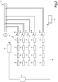
- a generic multi-client/multi-server network or system 1 is schematically represented.
- the system 1 can be comprised of a plurality of servers 3.1, 3.2, 3.3, 3.4.
- Each server 3.j is a master device, whereto a plurality of slave devices or clients 5.1-5.n can be connected, so as to be in data communication relationship therewith.
- each client is in data communication relationship with only one server.
- a first group 6.1 of clients is in data communication with server 3.1
- a second group 6.2 of clients is in data communication with server 3.2
- a third group 6.3 of clients is in data communication with server 3.3
- a fourth group 6.4 of clients is in data communication with server 3.4.
- a generic server will be designated simply with reference number 3
- a generic client will be designated with reference number 5
- a generic group of clients will be designated with reference number 6.
- each group 6 of clients 5 comprises the same number of clients 5, it will become apparent from the following description that the number of clients 5 assigned to each server 3 can be different. Moreover, in the schematic representation of Fig. 1 six clients 5 are assigned to each server 3. It shall however be understood that this is by way of representation only and that in real installations a usually larger number of clients 5 can be in data communication relationship with each server 6. For instance each server 3 can comprise up to 30 communication slots or more, to connect with a corresponding number of clients 5.
- Reference numbers 9 and 10 schematically represent communication channels between clients 5 and servers 3, and between servers 3 and a gateway 11, respectively. All servers 3 are connected to gateway 11.
- the gateway 11 can be connected to a remote monitoring center station 13.
- Channels 10 can be wired or wireless channels and may ensure a large bandwidth, for instance they can form a TCP/IP network (e.g. Ethernet, Wi-Fi, or the like).
- Small bandwidth channels 9, e.g. wireless connection channels can connect each client 5 to the respective server 3, which includes a relevant access point for connection to clients 5.
- One aspect of the methods disclosed herein concerns the manner in which clients 5 connect to a respective server 3 for optimal load balancing.
- Other aspects of the methods disclosed herein concern ways to dynamically adapt the configuration of the multi-client/multi-server system 1, e.g. to variable environmental conditions, which may affect the strength of the transmission signal, for instance, or events which may cause one or more servers 3 to become inoperative.
- clients 5 can be any kind of electronic devices.
- some clients 5 are inverters or micro-inverters of a photovoltaic panel installation.
- clients 5 can be electronic devices of the same kind or category (e.g. all inverters or micro-inverters), or else they can include electronic devices of different kinds, for instance inverters, repeaters, network extenders, sensors and the like, in combination.
- the inverters or micro-inverters have input terminals electrically connected to photovoltaic panels and output terminals electrically connected to an electric power distribution grid.
- the DC current generated by the photovoltaic panels is converted into AC current by micro-inverter.
- the AC current is delivered to the electric power distribution grid to power local loads and/or for distribution to a public electric power distribution grid.
- Fig. 2 schematically illustrates a portion of a photovoltaic plant comprised of rows of photovoltaic panels 15, each connected to a respective inverter or micro-inverter 5 (5.i, 5.i+1, 5.i+2, ).
- the clients 5 e.g. inverters, micro-inverters, or other electronic devices
- each micro-inverter 5 is in data communication relationship with at least one server 3 (3.i, 3.j).
- each client 5 can take several statuses and perform several actions, in order to join the clients/servers network.
- Fig.3 schematically illustrates four statuses, which each client 5 can take. Arrows schematically represent actions which a client 5 can perform to switch from one status to another.
- the four client statuses represented in Fig.3 are defined as follows:
- each client 5 can move from one status to another.
- a client 5 in an IDLE status can switch to the JOINED status through a "first join" action.
- a client 5 can be switched back from a JOINED status to an IDLE status through a reset action.
- a client 5 can also be switched back into the IDLE status from a SERVICE status.
- a client 5 in a JOINED status can switch to an ORPHAN status, for instance if the network is lost, i.e. if for whatever reason communication between the client 5 and the selected server 3, whereto the client 5 is joined, is interrupted.
- Each client 5 in an IDLE status has to join a server 3 of the network 1 to start communication therewith and with the gateway 11.
- the IDLE status differs from the ORPHAN status since the IDLE status is taken by a client 5, which has never joined the network or system 1, or has been reset. Conversely, the ORPHAN status is taken by a client 5, which has lost connection with a server 3, it was previously connected to.
- a client 5 in an IDLE status will send repeated requests for connection to a server 3.
- the request for connection to a server 3 can be a broadcast message, addressed to all servers 3 of the network 1.
- a server 3 receives a request for connection from a client 5, the server 3 has to decide whether or not the request for connection can be accepted.
- a routine is provided, for establishing a client-server connection, according to a connection policy. Embodiments disclosed herein provide for routines which allow a balanced distribution of clients 5 among the various servers 3 of the system 1.
- each server 3 which receives a request for connection from a client 5 in an IDLE status, calculates a figure of merit (herein after also shortly named FoM), based upon which the probability of establishing a connection with the requesting client 5 is calculated.
- the FoM is calculated on the basis of more than one factor, for instance a server-depending factor and a client-depending factor, or else a client-depending factor and a transmission channel-depending factor, or a server-depending factor and a transmission channel-depending factor or combinations of more than two factors.
- Each factor can be expressed as a percentage, i.e. its value can range between 0 and 99.
- a server-depending factor is any factor, which depends upon one or more conditions, parameters or statuses of the server 3.
- the server-depending factor can take into account the number of available slots, i.e. the total amount of possible server-client connections which the server 3 can support, minus the number of clients 5 already connected to said server 3. If N is the total number of available slots and M is the total number of clients 5 which already joined the server 3, the number of available slots is N-M.
- server-depending factor can be the server reaction time.
- server-depending factors can include the traffic amount and/or the amount of data stored in a server.
- a client-depending factor is any factor, which depends upon one or more conditions, parameters, statuses of the client 5. According to exemplary embodiments disclosed herein, a client-depending factor can be the number of unsuccessful requests for connection already sent by that specific client 5.
- Each server 3 can comprise a counter for a given client 5, which is increased each time a request from that client 5 is received and that client is not accepted by the server, and which may be decreased periodically, e.g. as a function of time.
- each client 5.j can be identified by a client identification number ID_clientj. Said ID_client_j identification number can be transmitted along with the request for connection, such that any server 3 receiving the request for connection can also indentify which client 5 is sending the request for connection. In this way, each server 3 can be programmed to store the number of requests for connection received by each client 5.
- each client 5 can include a counter, which counts the number of requests for connection generated by that client 5, said information being transmitted along with the request for connection.
- Each server 3 will thus be informed about the number of requests for connection generated by a given client 5 and can use said number as a client-depending factor to calculate the FoM.
- Another client-depending factor can be the kind and amount of data generated by the client.
- clients 5 need not to be identical to one another and may even belong to different categories of devices.
- Inverters and micro-inverters are typical clients which generate a large amount of data, while sensors are clients which generate less data.
- a factor taken into consideration in the FoM calculation can be therefore the intensity of data traffic generated by a client.
- a server that is already handling a large number of data may calculate a higher FoM for a client which is a low-traffic generator, and a smaller FoM if the client is a high-traffic generator.
- each client 5 can comprise a buffer storage memory, wherein data are temporarily stored.
- the buffer storage memory can store data on voltage, current, power, temperature or other operating parameters or status, alarms, logs of events related to the device, as a function of time. Data can be periodically sampled to collect information on the above mentioned parameters as a function of time.
- a client-dependent factor for the calculation of the FoM can include the buffer storage memory available for that particular client 5.
- clients 5 having less available storage memory take precedence over clients 5 having a larger available buffer storage memory, in order to avoid loss of collected data.
- the available buffer storage memory can thus be used as a client-dependent factor for calculating the figure of merit.
- Information on available buffer storage memory can be transmitted by client 5 to servers 3 along with the request for connection.
- a transmission channel-depending factor is any factor, which depends upon one or more conditions, parameters, statuses of the transmission channel 9.
- the strength of the transmission signal can be used as a parameter indicative of the transmission quality.
- environmental conditions such as weather conditions, external sources of electromagnetic noise and the like can strongly affect the strength of the radio signal transmitted by a client 5 and received by the servers 3.
- joining the server 3, which receives the strongest signal from a given client 5 can contribute to optimum exploitation of the transmission bandwidth, since it is in general preferable for a client 5 to join that server 3, wherewith the best data communication conditions can be established.
- a transmission channel-depending factor for the calculation of the FoM can be the strength of the signal received by the server 3.
- a transmission channel-depending factor is the number of clients each server 3 "sniffs" in the communication network. This can help the server to figure out who and how other servers perform the client management and make appropriate informed decisions.
- Two or more of the factors mentioned above can be used in combination to one another. Different combinations of different factors can be used.
- one, some or all factors used for calculating the FoM can be weighted with a constant or variable weight, such that either one or the other of said multiple factors can have a stronger influence on the resulting FoM.
- the weights ⁇ , ⁇ , ⁇ can be constant. In other embodiments, however, one, some or all weights ⁇ , ⁇ , ⁇ can be variable. For instance, if the number of available slots is particularly high, i.e. if there are much less clients 5 than there are slots available in that particular server 3, the weight applied by the server 3 to factor A can be high. However, if the number of clients increases, e.g. as more clients 5 are added to the system 1, the weight applied to factor A can be reduced.
- one or more servers 3 can be connected to one another, such that information can be exchanged between servers 3. While it is not necessary for all servers 3 of a network 1 to be in mutual data communication relationship, communication between all servers 3 can be useful under certain conditions. Communication between servers 3 can be obtained through channel 9. Each server 3 can thus use data from other servers 3 of the network 1 to calculate the FoM when a request for connection is received by a server 3 from a client 5. Thus, according to some examples, a further server-dependent factor can be used in calculating the FoM, which factor can be dependent upon information exchanged between servers in mutual data communication relationship.
- the total number of already connected clients 5 can be known if all servers 3 of the network 1 are in mutual data communication relationship.
- the information can be even more detailed and can include the number of clients 5 connected to each server 3.
- the FoM can then cure a situation where the server 3 receiving a request for connection determines that it has a number of clients 5 already connected thereto which is substantially lower (or else substantially higher) than the number of clients connected to other servers. This information can be used as a factor in the calculation of the FoM.
- server 3 determines that the number of clients 5 connected thereto is lower than the mean number of clients 5 connected to the remaining servers, a high value can be attributed to the factor involved in the calculation of the FoM. A low value for said factor will be used in the opposite situation.
- an exchange of information between servers 3 can further be used to assess which server 3 has calculated the highest FoM for a given requesting client 5 and will thus establish a connection with the requesting client 5.
- the server 3 which calculated the highest FoM will accept the requesting client 5 and initiate a data exchange relationship therewith.
- a requesting client 5 transmits a broadcast connection request
- several servers 3 will usually receive the request and each of them will calculate the relevant FoM.
- the network 1 can be configured to compare several FoMs calculated by several servers 3 for one and the same request for connection. The highest FoM will automatically determine which server 3 will accept the requesting client 5 and establish a connection therewith.
- One, some or all servers 3 can be configured to receive and compare FoMs from a plurality of servers 3. Or a dedicated device, such as the remote monitoring center station 13 can be in charge of establishing which is the highest FoM.
- the routine for connecting a client 5 requesting a connection can for instance provide for the following steps:
- routine for connecting a client 5 requesting a connection can for instance provide for the following steps:
- each server 3 can include a random number generator which generates numbers comprised between 0 and 99. Once the FoM has been calculated and a random number has been generated, the random number and the FoM are compared. If the random number is comprised between 0 and the calculated FoM, the requesting client 5 is accepted and the server 3 transmits a connection-accepting response to the requesting client 5. If the generated random number is higher than the calculated FoM, the request is not accepted. In this latter instance, a connection-refusing response can be transmitted to the requesting client 5.
- the server can simply provide no response to the request. In both cases the request from the requesting client 5 is refused by the server 3, either actively through a connection-refusing response, or passively, i.e. by not responding to the request.
- an external parameter e.g. the environment temperature
- a temperature sensor providing a temperature with accuracy up to one hundredth of a degree Celsius can be used and the last two digits of the temperature value can be compared with the calculated FoM.
- XX.yy °C be the measured temperature: the number yy will be compared with the calculated FoM.
- the requesting client 5 will receive a connection-accepting response or a connection-rejecting response (which may also include the case of no-response from the server) as follows: if 00 ⁇ yy ⁇ FoM a request-accepting response is transmitted if FoM ⁇ yy ⁇ 99 no response is transmitted, or a request-rejecting response is transmitted.
- the FoMs calculated by several servers 3 for a given client 5 requesting connection can be compared and connection is established with the server 3 which calculated the highest FoM.
- Selection of the highest FoM can be performed by the servers 3, or can be performed by the remote monitoring center station 13.
- one or some servers 3 can be selected to act as masters, which receive the FoMs values calculated by several servers and comparing the calculated FoMs to select the highest one.
- the above described routines allow a balanced distribution of clients 5 among several servers 3 of the system 1.
- a client 5 which receives a connection-accepting response and joins a server 3, switches from the IDLE status to the JOINED status.
- the connection-accepting response may contain the ID_server_j identification number of the server 3.j.
- the client 5.i will therefore identify the server 3.j it is joined to.
- the server 3.j, whereto the client 5.i is joined can be configured to receive and store the ID_client_i identification number of client 5.i.
- each server 3 generates and stores stored list of all clients 5 connected thereto and all clients store the relevant ID_server_j identification number.
- the network 1 can be identified by a network identification number ID_Network.
- Each server 3 and each client 5 can store the ID Network identifying the network 1, it is joined to.
- each server 3.j it is not essential for each server 3.j to have a univocal ID_server_j. Actually, in some embodiments all servers 3 of a given system may have the same ID_server_j identification code or identification number. According to other embodiments, each server 3j can have its own ID_server_j identification number and store the ID_Network identification number, to identify the network 1, the server belongs to.
- the newly added client 5 will be in an IDLE status and will start a routine for joining one of the available servers 3.
- the method described so far ensures correct distribution of clients 5 among servers 3, to obtain a fair load balancing and taking into consideration also possible environmental conditions, which may affect the strength of the transmission signal.
- a client 5 Once a client 5 is in a JOINED status, several events can cause loss of connection. For instance, weather conditions (snow, rain or fog) may have an impact on wireless communication. Similarly, electromagnetic disturbances can generate noise, which adversely affects the client-server communication and may lead to disconnection. In solar plants, clients and servers will switch off at sunset, due to loss of power supply. In wind turbines installations, clients and servers can switch off when wind stops. In those instances, one, some or all clients 5 in a JOINED status will switch into an ORPHAN status. In the diagram of Fig. 3 this event is represented by the arrow marked "network loss".
- a client 5.i in an ORPHAN status will generate a request for connection to the server 3.j, it was previously connected to, i.e. to the server identified by the identification number ID_server_j. Re-joining from an ORPHAN status, therefore, does not require the above described routine to be performed again.
- more servers 3 can have the same identification number ID_server_j.
- a client in an ORPHAN status may join either one or the other of the servers identified by the same ID_server_j identification number.
- each server 3.j may store the ID_client_i identification number of each client 5.i connected thereto. Now, if a client 5.i in an ORPHAN status requires connection to server(s) identified by the server identification number ID_serverj, only the server 3.j, whereto the requesting client 5.i in the ORPHAN status was previously connected, will accept the client 5.i again and set it back into the JOINED status.
- each client 5 and each server 3 can have the network identification number ID network stored therein.
- a client 5 requesting to rejoin the server from an ORPHAN status will transmit a request to rejoin, that can contain the server identification number ID_server_j and the network identification number ID_network, such that the servers receiving the request can immediately recognize if the requesting client 5.i belongs to the same network 1. Wrong associations between clients and servers belonging to neighboring networks is thus avoided.
- the ID_network identification number can be used instead of, or in combination with the ID_server_j identification number. In this case the ID_network identification number can be used for rejoining.
- a client 5 in an ORPHAN status can join any server of the network 1.
- Each server receiving a request for connection can be configured to accept the request only if the requesting client 5.i is in the list of previously connected clients 5. Rejoining becomes a fast procedure.
- a server 3.j receiving a request for connection from an orphan client 5.i can start a FoM calculation routine and determine whether or not to accept the requesting client, irrespective of whether said client was previously connected to said server or not. This will cause a re-distribution of clients among servers when switching from the ORPHAN status to the JOINED status again.
- the method can be configured to prevent interruption of communication or to restore communication between clients 5 and the remote monitoring center station 13 when a server 3.j becomes either permanently or temporarily inoperative.
- a server 3.j may become permanently inoperative in case of fault or breakdown, for instance.
- a server 3.j may become temporarily inoperative, e.g. due to a temporary loss of connection caused by a disturbance on the transmission channel 10 or on the transmission channel 9.
- any client 5.i connected thereto can be joined to the remaining server 3.j(2) with the same ID_server_j as follows.
- the clients 5.i(1) connected thereto switch in an ORPHAN status and start sending a request to join.
- Server 3.j(2) which is still operative receives the request for connection and determines that the requesting client 5.i(1) is not in the list of clients connected thereto.
- Server 3.j(2) can be configured such that it will not accept the requesting client 5.i(1) until a given delay time ⁇ t has lapsed.
- server 3.j(2) will accept the requesting client 5.i (1), either immediately or upon calculation of a FoM. If several servers 3.j share the same ID_server_j identification number, each of said servers will perform the same routine. The requesting clients 5.i(1) which were switched into the ORPHAN status following breakdown of server 3.j(1) will thus gradually rejoin one or the other of the remaining servers 3.j which are still operative and have the same ID_sever_j identification number.
- each server 3.j has its own univocal ID_server_j identification number
- the above re-assignment procedure can be run on the basis of the ID_network identification number or code.
- the clients 5.i which switch in the ORPHAN status as a consequence of server 3.j breakdown will start sending a request for connection.
- the remaining servers will determine that the request comes from a client belonging to the same network (which is evidenced by the ID_network identification number contained in the request for connection).
- the servers 3 which are operative will run a FoM calculation routine as described above, to join the requesting client to a new server 3.
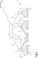
- Fig.4 The result of clients re-assigment in case of a sever breakdown is pictorially represented in Fig.4 .
- server 3.2 is assumed to be broken
- the clients 5.i-5.j belonging to group 6.2 are re-assigned partly to server 3.1 and partly to server 3.3.
- the above described status/action scheme provides an additional anti-theft feature. If the client-server connection is lost e.g. because the client is fraudulently removed from the system 1, the client 5 will switch into the ORPHAN status and will not join a server of another network or system 1 and becomes therefore unusable.
- each server 3 may contain information on all clients 5 belonging to the system 1.
- a storage memory can be provided for that purpose in each server 3 or in some of said servers. This can be done by loading the ID_client_j identification numbers manually in each server, or by transmitting said information to each server 3 from the remote monitoring center station 13 through the gateway 11 and the channel 10. Two additional functions can thus be achieved.
- an anti-theft function is added to the servers 3.
- Each server 3 can accept only clients 5 of the network or system 1, it belongs to, and will become useless if introduced in a different system.
- two systems are installed at a distance such that clients 5 of one system can be "seen" by servers 3 of the neighbor system, no overlapping or erroneous assignment of clients 5 of the first system to servers of the second system, or vice-versa, is possible.
- the client 5 can switch from the ORPHAN status to a SERVICE status, as represented in Fig.3 . This can occur after a pre-set timeout.
- a client 5 which is in the SERVICE status can be re-set in the IDLE status.
- the clients 5 can be configured such that they switch back into the ORPHAN status after a given period of time.
- the two arrows labeled "timeout" between the ORPHAN status and the SERVICE status in Fig.3 indicate that a client 5 can be switched back and forth between the ORPHAN status and the SERVICE status. If the event which caused a client 5 to switch into the ORPHAN status ceases, the client 5 can thus connect to its server 3 again. For instance, if a broken server 3 is replaced by a new server 3, and if the new server 3 is given the same ID_server_j identification number, all clients 5 previously joined to the broke server will join the replacing server 3.
- a client 5 is set in the SERVICE status and cannot connect to its server 3 again, e.g. because the server is broken and is not replaced and a re-assignment routine to a different server is not provided for or does not operate properly, the anomalous situation can be detected at the remote monitoring center station 13, for instance because no data from the client 5 concerned are received anymore.
- a manual service intervention can then be triggered.
- service intervention can be performed by personnel in charge of the system 1.
- the client 5 which is in the SERVICE status and does not succeed in getting back in the JOINED status is reset into an IDLE status manually. This action is schematically represented by arrow "re-set" in Fig. 3 , connecting the SERVICE status with the IDLE status. Once the client 5 has been reset in the IDLE status, it will perform the above described routine for joining a new server 3.
- the above described method of operation can be further improved in order to cope with variable network conditions, for instance.
- weather or other factors such as electromagnetic noise or the like can have an impact on the strength of the signal.
- the conditions may change during time to such an extent that the selected client-server connections are not optimized under modified conditions.
- each server 3 can reject one or more clients 5 assigned thereto and reset said client(s) back in the IDLE status.
- This action is represented in the scheme of Fig.3 by the arrow marked “reset” between the JOINED status and the IDLE status of a generic client 5. This function allows the client-server connections to be modified and dynamically adapt the system to variable conditions.
- the rejection function and consequent reset in the IDLE status can be used to achieve different goals, as will be described here on.
- the rejection and reset function can be used to cyclically reject one or more clients and allow other clients 5 from a waiting list to join the rejecting server 3.
- the rejection and reset function can be further used to manage situations where the number of clients 5 is small enough to be managed by the servers 3 provided in the network 1, but one or more servers 3 become temporarily or permanently unavailable, e.g. due to breakdown or fault.
- a re-assignment of the clients 5 switched to the ORPHAN status due to server breakdown can be provided, to distribute the clients 5 in the ORPHAN status to a new server 3.
- the number of total available slots may become less than the total number of clients 5 to be connected.
- the rejection and reset function can also be used to re-arrange the server-client connections to take into account possible variable environmental conditions, variability of the total number of active clients 5, or any other dynamic occurrence that may affect the overall structure or operation of the network 1.
- each client 5 connected to a server 3 can be cyclically rejected upon expiration of a maximum connection time, for instance.
- the rejected client 5 is reset in the IDLE status and will start a routine for joining a server 3 again.
- the newly established connection can be the same as the previous one, i.e. the client 5 can join the same server 3.
- the client 5 can join a different server 3. This will depend upon the actual conditions of system or network 1 at the time the request for connection is issued by the client 5.
- Re-joining can be through a FoM calculation routine as described above.
- a figure of merit for rejection (here on shortly referred to as FoMR) is calculated by a server 3, to establish if and which one of the clients 5 connected thereto will be rejected and reset in the IDLE status.
- the FoMR can be calculated on the basis of one or more factors.
- the FoMR determines the probability for a given client 5 to be rejected by the respective server 3 and be reset in the IDLE status.
- one factor, upon which the FoMR for a given client 5 can be calculated is based on the strength of the signal received from the client 5 concerned.
- the strength of the signal can be expressed as RSSI.
- the contribution to the FoMR can be the lower, the higher the RSSI is. This means that clients 5, wherefrom the server 3 receives a weak signal, have a higher percentage of probability of being rejected.
- the system will attempt to re-distribute clients 5 to get improved connection signals. Since the strength of the signal can vary as a function of events, such as environmental conditions, the FoMR calculated for a given client 5 can vary during time.
- the FoMR can be calculated cyclically, at regular or random intervals, and for the same client 5 the FoMR can change.
- another factor upon which the FoMR can be calculated, takes into account the amount of buffer storage memory, which is available for a given client 5 for collecting data. Since a client 5 in an idle status cannot transfer data from the buffer storage memory thereof to the gateway 11 through server 3, the less space is available for data storage, the lower is the chance for the given client 5 to be rejected and reset in an idle status. This factor takes into account the need of avoiding loss of data.
- yet further factor upon which the FoMR for a given client 5 can be calculated, is a function of the previous status of the client 5. If the client 5 concerned has remained for a long time in an IDLE status before receiving a connection-accepting response to join the server 3, the probability of being set in the IDLE status again shall be low. Such factor is aimed at making the time of lack of connection as uniform as possible among the various clients belonging to the network 1, and to avoid a situation where some clients 5 will remain in the IDLE status for a longer time than others.
- the FoMR can be calculated on the basis of one, two or more factors used in combination. Each factor can be weighted and each weight can be either constant or variable. In some embodiments, one or more weights can be a function of one or several other weights or factors.
- the FoMR can be a function (g) of one or more factors A', B', C'. Each factor can be weighted with a weight ⁇ ' , ⁇ ', ⁇ '.
- the routine for rejecting a client 5 and resetting said client 5 in the IDLE status is similar to the routine for switching a client 5 from the IDLE status to the JOINED status.
- the FoMR is calculated and given a value comprised between 0 and 99.
- a number between 0 and 99 is generated in any suitable manner, e.g. through a random number generator, and the two entities are compared. If the random number is comprised between 0 and FoMR, the client 5 is rejected, otherwise it remains joined to the server 3. Since the rejected client 5 is placed in the IDLE status, it will start the procedure to join a server 3 again.
- the server 3 can calculate a FoMR for each client connected thereto and reject the client 5 for which the highest FoMR has been calculated.
- a rejection policy can be coordinated among several servers 3.
- clients 5 will be selectively rejected based upon the calculated FoMR and by comparing FoMRs for clients 5 joined to different servers. It can thus be envisaged that FoMRs calculated by several severs 3 are compared, and the client(s) with the higher FoMR(s) among all the clients 5 connected to the various servers (or some of said clients) is(are) rejected.
- the number of clients rejected by each server 3 can vary from server to server.
- a conditioning function can be provided, such that, in addition to selecting the client 5 to be rejected, a threshold to the maximum number of clients that can be rejected by one and the same server 3 can be set.
- the network 1 Since clients 5 are rejected and reset in the IDLE status, the network 1 is capable of managing a number of clients 5 larger than the total number of available slots. In such case, there will always be a waiting list of queueing clients 5 in the IDLE status, requesting connection to a server.
- the number Q of queueing clients 5 will normally be equal to the total number of clients 5 minus the total number of slots available. This, however, is not mandatory. In some conditions the number of queueing clients can be higher, e.g. if one or more servers 3 can temporarily not be reached.
- the frequency of rejections can be set a priori for each server 3, or can be changed according to needs.
- the frequency of rejections i.e. the frequency at which each server 3 rejects a client 5 by resetting it into the IDLE status, can depend upon the number of clients 5 of the system in excess of the total available slots, i.e. to the number of queueing clients 5.
- the frequency of rejection can be determined on the basis of the total number of clients 5 connected to a server 3. The larger the number of clients connected, the higher the frequency of rejection.
- the frequency of rejection for each server 3 can be modulated according to the actual distribution of clients among several servers. For instance, servers 3 having a larger number of clients 5 connected thereto can be given a higher frequency of rejection, and servers 3 having a smaller number of clients 5 connected thereto can be given a lower frequency of rejection.
- measures can be taken to reduce the queueing time.
- the number of queueing clients 5 requesting to re-join a server 3 can be used to accelerate the rejection rate.
- the presence of servers 3, which are in a fault condition may also be used to increase the rate of rejection. In both cases a factor taking into consideration the above mentioned conditions may be added in the formula for the calculation of the FoMR.
- rejection of a client 5 is determined by switching the client from the JOINED status to the IDLE status.
- the rejection may be determined by switching the client 5 from the JOINED status to the ORPHAN status.
- some or all servers 3 are identified by the same ID_server_j identification number, or if a common ID_network identification number is used, a dynamic adaptation of the network 1 is possible through cyclic rejection and re-joining, even if the clients 5 are switched in an ORPHAN status rather than in an IDLE status.
- a client 5 which is rejected by a server 3.j by switching the client 5 in an ORPHAN status, will be rejoined to one of the servers of said sub-groups.
- each client 5 which is rejected and switched in the ORPHAN status, will start a routine for joining a server 3 and will be potentially able to join any one of the servers 3 in the network 1.
- the servers 3 can communicate to one another.
- One purpose of mutual communication between servers 3 can be to set and/or modify a policy used for calculating the FoM and/or the FoMR.
- servers 3 can communicate with one another to set appropriate weights for the calculation of the FoM and/or the FoMR.
- servers 3 can communicate with one another, so that each server 3 is informed about the total number of clients 5 which are in the system 1, or the total number of clients in the JOINED status. It can also be possible for each server 3 to know how many clients 5 are in data communication relationship with each other server 3. This information can be used, for instance, in order to start a rejection routine if an unbalanced situation is noticed. Servers 3 having a higher load, i.e. a larger number of clients 5 connected thereto, may be forced to initiate or accelerate a rejection policy. If one or more servers 3 are connected to an overly large number of clients compared to other servers 3, the rejection policy may assist in re-balancing the distribution of client-server connections.
- data communication between servers 3 is used by a server 3 to check if the client 5 which it intends to reject can be accepted by another server and the FoMR can be calculated on the basis of a factor that depends upon the probability for the client 5 to be joined to another server 3.
- Transmission channel sniffing techniques can be used, for instance, to determine how many of the remaining servers can "see" the client 5 which is about to be rejected.
- the rejecting server 3 can determine whether and how many other servers 3 have available slots to accept the client 5, which is about to be rejected.
- the FoMR can be calculated taking this factor into consideration.
- data from other servers 3 can be used as a further server-depending factor in the calculation of the FoM or of the FoMR. For instance, if a client 5 in an IDLE status is requesting connection, the FoM calculated by a server 3 receiving the request can take into consideration how many other clients 5 are already joined to the remaining servers 3. If the server 3, which calculates the FoM has a number of clients 5 already connected thereto, which is lower than the mean number of clients 5 connected to each remaining server 3, the FoM will be increased accordingly. The FoM will be decreased if the number of clients 5 already connected to said server 3 is higher than a mean number of clients 5 connected to the remaining servers 3.
- the servers 3 are configured to periodically check if each server 3 of the system is operative. Exemplary embodiments provide for routines for this purpose. If the checking routine is successfully completed, all servers 3 are operating. If one server 3 is broken, information on the broken server can be obtained.
- a checking routine include sending a broadcast checking message. Each server 3 replies to the checking message. If a response is missing, the server 3 is broken.
- One of the servers 3 of the system 1 can be configured as a master to perform this routine. The master will broadcast the checking message and collect the received responses, one from each remaining server 3. Each response contains information sufficient to identify the responding server 3. The master can alert the remote monitoring center station 13 if one or more servers 3 do not reply to the checking message.
- the checking routine can be run through the remote monitoring center station 13. This latter may send a command message, asking all the servers 3 to provide a response indicative of their status. A broken server 3 will not respond.
- servers 3 have self-test capability, information on the problem of a non-properly working server 3 can also be collected at the remote monitoring center station 13. Service intervention can thus be programmed.
- the remote monitoring center station 13 can be programmed to determine whether regular data flows are received from each server 3 of the network 1. Absence of data flow, or altered data flow from one server 3 can be interpreted as an alert on possible server malfunctioning. The remote monitoring center station 13 can be programmed to perform a status check on the server concerned.
- an anomalous situation concerning one of the servers 3 of the network 1 detected by the remote monitoring center station 13 can start a client-reassignment routine.
- the client-reassignment routine is controlled by the remote monitoring center station 13.
- Information is transmitted to the remaining servers 3 that the clients 5 assigned to the malfunctioning or broken server 3 shall be re-assigned.
- Each one of the remaining servers 3, which receives a request from the clients 5 in the ORPHAN status previously assigned to the malfunctioning or broken server 3, will accept the request for connection.
- the re-assigned clients 5 may store the ID_server_j identification number of the new server 3 and the new server 3 will store the ID_client k identification number of the newly connected client 5, for future rejoining from the ORPHAN status.
- a re-balancing routine can be started to re-balance the client distribution.
- a re-balancing routine command can be sent by the remote monitoring center station 13 once the server 3 has been replaced.
- the re-balancing routine can involve a rejection routine by the servers other than the newly replaced one. Rejections of the clients 5 in the JOINED status will gradually re-balance the clients distribution among the servers 3.
- the multi-client/multi-server network 1 is established by connecting each client 5 to a respective server 3 through a routine that involves the calculation of a figure of merit FoM, based on one or more factors.
- a figure of merit for rejection FoMR can be calculated, which is used to re-balancing the network, e.g. in order to take into account events that may change the conditions of the network.
- a rejected client 5 will start a routine for rejoin a server 3, which involves the calculation of the FoM.
- the criterion of cyclically rejecting clients 5 which are already connected to a server 3, in order to improve the network balancing can be used also in combination with a different way of establishing the first or subsequent client-server connection.
- any method can be used to create a first multi-client/multi-server network, irrespective of how inefficient the method is.
- the network can be balanced by cyclically causing each server 3 to reject one or more of the clients 5 connected thereto, by using the above described routine based on the calculation of a Figure of Merit for Rejection FoMR. This will automatically re-balance the network, gradually and automatically achieving an optimum balanced network structure.
- Each client 5 which has been rejected by the server 3 it was connected to can join a server 3 again using the method described above, involving the calculation of a Figure of Merit (FoM).
- the rejected client 5 can join a server 3 again using any possible connection method, e.g. those known from the current art.
- the aforementioned examples do not form part of the invention.
Description
- The present invention concerns multi-client/multi-server systems and methods for managing said systems.
- Generally speaking, a multi-client/multi-server system is an aggregate comprised of several electronic devices operating as clients, which are in data communication with a plurality of electronic devices operating as servers. Each client is in a data communication relationship with at least one server. Each server is in turn in data communication relationship with at least one client, and usually with a plurality of clients. Servers can be connected to a gateway for communication with a remote monitoring center station. The servers are connected to the gateway through a fast and reliable communication channel, e.g. a TCP/IP network, which permits managing a high data bandwidth to forward information to the gateway. A wireless or a wired network is provided for connecting clients and servers.
- Examples of multi-client/multi-server systems of this kind can be found e.g. in the field of renewable energy installations, such as wind turbine installations, fields of photovoltaic panels, fuel cells, and the like. The use of low-power devices, e.g. micro-inverters, involves the use of a large number of such inverters, e.g. up to several hundreds of inverters, which are distributed on the field. Each inverter represents a client of the multi-client/multi-server system. Each client is connected to a server and, due to the large number of clients, a plurality of servers are needed.
- The channels connecting the clients to the servers must be managed carefully to prevent overload of communication data or problems related to the available bandwidth, for instance.
- The physical positioning of the electronic devices (e.g. inverters connected to photovoltaic panels, wind turbines, fuel cells, or other renewable energy resources) on the field is not always predictable. Sometimes the photovoltaic panels, and therefore the electronic devices connected thereto, are installed on asymmetric roofs. In other situations they are spread over extensive fields.
- One critical aspect of a multi-client/multi-server system concerns balancing the communication load between clients and servers in terms of data traffic bandwidth.
- In some cases, clients are connected to the network through respective servers when they are powered by a renewable energy resource and leave the network when no energy is available. For instance, in solar power plants the inverters will connect to the network at sunrise and will leave the network at sunset. Similarly, inverters coupled to wind turbines will connect to the network only when wind is available. When the clients require connection to the network again, e.g. at sunrise, or when wind starts blowing again, the communication between each client and the respective server must be re-established correctly.
- Especially when a wireless network is used to connect clients to servers, environmental factors can adversely affect client-server communication. In some cases, client-server connection can be lost. A client-server re-assignment may become necessary in such situations.
- Various criteria have been developed to assign clients to servers in a multi-client/multi-server environment, to achieve proper load balancing. These criteria proved to be unsatisfactory.
-
US 8499086 discloses a method for client load distribution in a multi-client/multi-server environment. Each server is adapted to re-assign single clients assigned to it to another server, for load distribution purposes. -
WO2007/001151 discloses a method and system for providing streaming service in home network, wherein a client requesting a streaming service transmits information about the priority of the request to the server. - A need therefore exists, for a more efficient criterion to manage load balancing in a multi-client/multi-server system.
- According to the invention, a method is provided according to
claim 1. - The figure of merit of rejection is a figure that takes into account one or more factors that are indicative for example of how the quality of the connection. The higher the figure of merit for rejection, the lower the quality of the connection. For example, the figure of merit for rejection can be calculated on the basis of the number of clients connected to a given server. The higher the total number of clients connected to said server, the higher the figure of merit for rejection, which indicates that the server is overloaded and the chance of rejecting one (or more) clients is consistently high. In this example, an identical figure of merit for rejection can be calculated for all clients connected to a given server, if the number of connected clients is the only parameter used. The figure of merit for rejection calculated for clients of a server, to which a low number of clients is connected, will be correspondingly low. In this scenario. The figure of merit for rejection can take into account not only the number of clients actually connected to a server, but also the number of total slots of that server, i.e. the highest number of connections which the server may support. In such case the figure of merit for rejection could e.g. be the inverse of the difference between the maximum number of clients connectable to the server and the number of actually connected clients.
- The process of establishing a client-server connection can be performed on the basis of novel methods disclosed later on, or using any other known method, even an inefficient one. The routine of calculating a figure of merit for rejection, will improve the balance and efficiency of the network even if an inefficient method is used to establish a server-client connection.
- The figure of merit for rejection can be calculated as a function of at least one of the following parameters: a quality of a client-server communication signal; an amount of buffer memory available for the client; a number of clients queueing for connection to a server; a number of total clients connected to the server; a number of total clients connected to servers of the system; or a combination of a plurality of said parameters.
- If two or more parameters are used, an improved efficiency is obtained. For example two parameters can be used in combination, such as the total number of clients connected to a server and the quality of client-server communication signal. For each client connected to a server a figure of merit for rejection will be calculated on the basis of the two parameters mentioned above. The first parameter will be the same for each client, since it depends on the total number of clients connected to a given server. The second parameter can be different for each client. The figure of merit for rejection can be directly proportional to the total number of clients connected (or to the inverse of the difference between maximum connectable clients and total number of connected clients) and inversely proportional to the power of the connecting signal. The chance for a client to be rejected will increase as the total number of connected clients increases, and will decrease as the strength of the transmission signal increases.
- This will cause a re-balancing of the network. Clients connected to overloaded servers will have a higher chance to be rejected, and thus to be re-joined to a different server. However, the chance of being rejected increases with decreasing transmission signal strength. Those clients connected to overloaded servers and having the weakest connections signal are those which will be most probably rejected.
- By repeating the rejection process again and again, with a chance for each client to be rejected being a function of the connection quality, will gradually cause a re-balancing of the network.
- If the figure of merit for rejection is calculated on the basis of more than one parameter, each parameter can be weighted or some of them can be weighted. Weighing factors can be used to multiply each parameter. The weighing factors can be constant, some can be constant and some variable, or all of them can be variable.
- In the above mentioned example, the number of total clients connected to a server can be given a low weight and the communication signal can be given a higher weight, such that the signal quality will be more important in determining the chance of a client to be rejected, i.e. the poor signal quality will weigh more than the overloading of a server in determining the chance of a client to be rejected.
- If the weights are not constant, e.g. one weighing factor can be variable as a function of another weighing factor or as one or more of the parameters involved in the calculation of the figure of merit for rejection.
- According to some embodiments, the step of connecting a client to a server can comprise the following steps:
- the client generates a request for connection;
- when one of the servers receives a request for a connection from one of the clients, the server connects the requesting client thereto.
- The method can include the following further steps:
- the server receiving a request for connection from a client calculates a figure of merit for the requesting client;
- the server sends a connection-accepting response to the requesting client with a probability, which depends upon the figure of merit;
- the requesting client receiving a connection-accepting response joins the server and starts communication therewith.
- The figure of merit, differently from the figure of merit for rejection, is used as a quality measure to provide a higher or lower probability for a given client to be joined to a given server.
- The method using a figure of merit for joining a client to a server can be used either when the network is established for the first time, or for establishing a new connection each time a client is rejected.
- Using both a figure of merit for joining a client to a server and a figure of merit for rejection for rejecting an already connected client results in a particularly efficient method of administering the network.
- The figure of merit can be calculated as a function of at least one of: a client-depending factor; a server-depending factor; a transmission channel-depending factor; or a combination thereof.
- For instance, the method can comprise the step of calculating the figure of merit on a combination of the following factors: a number of available slots of the server (i.e. the difference between maximum number of clients that can be connected to the server and total number of clients actually connected to the server); a strength of the transmission signal from the requesting client to the server; a number of requests for connection issued by the requesting client.
- Further features and embodiments of the method according to the invention are set forth in the appended claims and are disclosed in the following description.
- A more complete appreciation of the disclosed embodiments of the invention and many of the attendant advantages thereof will be readily obtained as the same becomes better understood by reference to the following detailed description when considered in connection with the accompanying drawings, wherein:
-
Fig.1 illustrates a schematic of a multi-client/multi-server system, in which methods disclosed herein can be implemented; -
Fig.2 schematically illustrates a portion of a photovoltaic panel installation configured as a multi-client/multi-server system; -
Fig.3 illustrates a diagram of the statuses and actions which can be taken by each client; -
Fig.4 illustrates the schematic ofFig. 1 in a situation where one of the servers is out of service. - The following detailed description of the exemplary embodiments refers to the accompanying drawings. The same reference numbers in different drawings identify the same or similar elements. Additionally, the drawings are not necessarily drawn to scale. Also, the following detailed description does not limit the invention. Instead, the scope of the invention is defined by the appended claims.
- Reference throughout the specification to "one embodiment" or "an embodiment" or "some embodiments" means that the particular feature, structure or characteristic described in connection with an embodiment is included in at least one embodiment of the subject matter disclosed. Thus, the appearance of the phrase "in one embodiment" or "in an embodiment" or "in some embodiments" in various places throughout the specification is not necessarily referring to the same embodiment(s). Further, the particular features, structures or characteristics may be combined in any suitable manner in one or more embodiments.
- In the following description, reference will specifically be made to a solar plant, comprised of an arrangement of photovoltaic panels and relevant inverters, these latter representing clients of a multi-client/multi-server installation. It shall however be understood that various features of the invention disclosed herein can be embodied in other kinds of installations and different environments, where clients and servers represent generic electronic devices in data communication relationship.
- In
Fig.1 a generic multi-client/multi-server network orsystem 1 is schematically represented. Thesystem 1 can be comprised of a plurality of servers 3.1, 3.2, 3.3, 3.4. Each server 3.j is a master device, whereto a plurality of slave devices or clients 5.1-5.n can be connected, so as to be in data communication relationship therewith. Usually each client is in data communication relationship with only one server. In the schematic ofFig. 1 , a first group 6.1 of clients is in data communication with server 3.1, a second group 6.2 of clients is in data communication with server 3.2, a third group 6.3 of clients is in data communication with server 3.3 and a fourth group 6.4 of clients is in data communication with server 3.4. Here below a generic server will be designated simply withreference number 3, a generic client will be designated with reference number 5 and a generic group of clients will be designated with reference number 6. - While in the schematic of
Fig.1 each group 6 of clients 5 comprises the same number of clients 5, it will become apparent from the following description that the number of clients 5 assigned to eachserver 3 can be different. Moreover, in the schematic representation ofFig. 1 six clients 5 are assigned to eachserver 3. It shall however be understood that this is by way of representation only and that in real installations a usually larger number of clients 5 can be in data communication relationship with each server 6. For instance eachserver 3 can comprise up to 30 communication slots or more, to connect with a corresponding number of clients 5. -
Reference numbers servers 3, and betweenservers 3 and agateway 11, respectively. Allservers 3 are connected togateway 11. Thegateway 11 can be connected to a remotemonitoring center station 13.Channels 10 can be wired or wireless channels and may ensure a large bandwidth, for instance they can form a TCP/IP network (e.g. Ethernet, Wi-Fi, or the like).Small bandwidth channels 9, e.g. wireless connection channels can connect each client 5 to therespective server 3, which includes a relevant access point for connection to clients 5. - One aspect of the methods disclosed herein concerns the manner in which clients 5 connect to a
respective server 3 for optimal load balancing. Other aspects of the methods disclosed herein concern ways to dynamically adapt the configuration of the multi-client/multi-server system 1, e.g. to variable environmental conditions, which may affect the strength of the transmission signal, for instance, or events which may cause one ormore servers 3 to become inoperative. - As mentioned, clients 5 can be any kind of electronic devices. In the exemplary embodiment described herein some clients 5 are inverters or micro-inverters of a photovoltaic panel installation. It shall moreover be understood that clients 5 can be electronic devices of the same kind or category (e.g. all inverters or micro-inverters), or else they can include electronic devices of different kinds, for instance inverters, repeaters, network extenders, sensors and the like, in combination.
- The inverters or micro-inverters have input terminals electrically connected to photovoltaic panels and output terminals electrically connected to an electric power distribution grid. The DC current generated by the photovoltaic panels is converted into AC current by micro-inverter. The AC current is delivered to the electric power distribution grid to power local loads and/or for distribution to a public electric power distribution grid.
Fig. 2 schematically illustrates a portion of a photovoltaic plant comprised of rows ofphotovoltaic panels 15, each connected to a respective inverter or micro-inverter 5 (5.i, 5.i+1, 5.i+2, .....). The clients 5 (e.g. inverters, micro-inverters, or other electronic devices) are electrically connected to the electricpower distribution grid 17 and each micro-inverter 5 is in data communication relationship with at least one server 3 (3.i, 3.j). - According to some embodiments, each client 5 can take several statuses and perform several actions, in order to join the clients/servers network.
Fig.3 schematically illustrates four statuses, which each client 5 can take. Arrows schematically represent actions which a client 5 can perform to switch from one status to another. The four client statuses represented inFig.3 are defined as follows: - IDLE: this is the status of the client 5 prior to being linked to the
network 1, e.g. when it is first delivered from a factory and installed insystem 1, or once it has been reset to factory default values. As will be explained later on, according to some embodiments this status can be forced by a server of the network; i.e. a client 5 can be forced back in the IDLE status by aserver 3, it has been previously connected to; - JOINED: this is the status where the client 5 is connected to a
respective server 3 and, through saidserver 3, with the remotemonitoring center station 13. The client 5 is in data communication with the remotemonitoring center station 13 and can send/receive data, commands or instructions. Eachserver 3 can be identified by a server identification number. E.g. server 3.j can be identified by identification number ID_server_j. Once joined to server 3.j, the generic client 5.i will be able to communicate with said server only, unless special reset actions are taken, as will be disclosed here below. The network orsystem 1 can in turn be identified by a network identification number ID Network; - ORPHAN: if, for whatever reason, communication between the client 5 and the
relevant server 3 is lost, the client 5 will be set in the ORPHAN status. This may happen e.g. due to loss of the communication signal in a wireless communication network, caused by temporary environmental disturbance factors. A client 5 can be set in the ORPHAN status for instance also due to a temporary loss of power supply to the client 5 and/or to therespective server 3. In solar power plants, all clients 5 will switch to the ORPHAN status at sunset, since the loss of power supply will turn the network off. Similar situations may occur e.g. in wind turbine installations in case of lack of wind; - SERVICE: in this status client 5 requires service intervention from the plant managing staff.
- As schematically represented by the arrows in
Fig.3 , each client 5 can move from one status to another. For instance, a client 5 in an IDLE status can switch to the JOINED status through a "first join" action. In some embodiments, a client 5 can be switched back from a JOINED status to an IDLE status through a reset action. According to the schematic ofFig. 3 a client 5 can also be switched back into the IDLE status from a SERVICE status. A client 5 in a JOINED status can switch to an ORPHAN status, for instance if the network is lost, i.e. if for whatever reason communication between the client 5 and the selectedserver 3, whereto the client 5 is joined, is interrupted. From the ORPHAN status the client 5 can switch back to the JOINED status or to the SERVICE status. From the SERVICE status the device 5 can switch to an IDLE status or back to an ORPHAN status. These switching actions will now be described in greater detail. The above mentioned statuses and actions can be provided in some exemplary embodiments of the system disclosed herein. In other embodiments a different number of statuses (for instance less) can be provided for and/or a different set of actions can be foreseen to switch from one status to another. - Each client 5 in an IDLE status has to join a
server 3 of thenetwork 1 to start communication therewith and with thegateway 11. As noted above, the IDLE status differs from the ORPHAN status since the IDLE status is taken by a client 5, which has never joined the network orsystem 1, or has been reset. Conversely, the ORPHAN status is taken by a client 5, which has lost connection with aserver 3, it was previously connected to. - When the system or
network 1 is first set-up, all clients 5 are in an IDLE status and must be switched into a JOINED status. If thesystem 1 is expanded, e.g. if additional photovoltaic panels and relevant micro-inverters (or other generic electronic devices such as sensors, repeaters, etc.) are added to the network orsystem 1, each newly added client 5 will be in an IDLE status and shall join thesystem 1 by establishing communication with one of theavailable servers 3. - To establish a new connection between a client 5 in an IDLE status and a
server 3, according to some examples the client 5 that is in the IDLE status will send repeated requests for connection to aserver 3. The request for connection to aserver 3 can be a broadcast message, addressed to allservers 3 of thenetwork 1. When aserver 3 receives a request for connection from a client 5, theserver 3 has to decide whether or not the request for connection can be accepted. According to some embodiments, a routine is provided, for establishing a client-server connection, according to a connection policy. Embodiments disclosed herein provide for routines which allow a balanced distribution of clients 5 among thevarious servers 3 of thesystem 1. - According to some examples each
server 3, which receives a request for connection from a client 5 in an IDLE status, calculates a figure of merit (herein after also shortly named FoM), based upon which the probability of establishing a connection with the requesting client 5 is calculated. In currently preferred embodiments, the FoM is calculated on the basis of more than one factor, for instance a server-depending factor and a client-depending factor, or else a client-depending factor and a transmission channel-depending factor, or a server-depending factor and a transmission channel-depending factor or combinations of more than two factors. Each factor can be expressed as a percentage, i.e. its value can range between 0 and 99. - In general terms, a server-depending factor is any factor, which depends upon one or more conditions, parameters or statuses of the
server 3. According to some exemplary embodiments, the server-depending factor can take into account the number of available slots, i.e. the total amount of possible server-client connections which theserver 3 can support, minus the number of clients 5 already connected to saidserver 3. If N is the total number of available slots and M is the total number of clients 5 which already joined theserver 3, the number of available slots is N-M. For instance, if the number N of slots available is 30 and the number M of clients 5 already connected to saidserver 3 is 10, the server-depending factor which is used to calculate the FoM can be a probability of accepting a new connection defined as
- Another server-depending factor can be the server reaction time. Yet further server-depending factors can include the traffic amount and/or the amount of data stored in a server.
- A client-depending factor is any factor, which depends upon one or more conditions, parameters, statuses of the client 5. According to exemplary embodiments disclosed herein, a client-depending factor can be the number of unsuccessful requests for connection already sent by that specific client 5.
- Each
server 3 can comprise a counter for a given client 5, which is increased each time a request from that client 5 is received and that client is not accepted by the server, and which may be decreased periodically, e.g. as a function of time. - According to examples disclosed herein, each client 5.j can be identified by a client identification number ID_clientj. Said ID_client_j identification number can be transmitted along with the request for connection, such that any
server 3 receiving the request for connection can also indentify which client 5 is sending the request for connection. In this way, eachserver 3 can be programmed to store the number of requests for connection received by each client 5. - In other examples, each client 5 can include a counter, which counts the number of requests for connection generated by that client 5, said information being transmitted along with the request for connection. Each
server 3 will thus be informed about the number of requests for connection generated by a given client 5 and can use said number as a client-depending factor to calculate the FoM. - Another client-depending factor can be the kind and amount of data generated by the client. As noted above, clients 5 need not to be identical to one another and may even belong to different categories of devices. Inverters and micro-inverters are typical clients which generate a large amount of data, while sensors are clients which generate less data. A factor taken into consideration in the FoM calculation can be therefore the intensity of data traffic generated by a client. A server that is already handling a large number of data may calculate a higher FoM for a client which is a low-traffic generator, and a smaller FoM if the client is a high-traffic generator.
- One of the purposes of establishing a connection between a client 5 and a
server 3 is to transmit data collected by the client 5 to the remotemonitoring center station 13 viachannel 9,server 3,channel 10 andgateway 11. In some embodiments, each client 5 can comprise a buffer storage memory, wherein data are temporarily stored. For instance, if the client 5 is a micro-inverter of a photovoltaic system or any other generic electronic device, the buffer storage memory can store data on voltage, current, power, temperature or other operating parameters or status, alarms, logs of events related to the device, as a function of time. Data can be periodically sampled to collect information on the above mentioned parameters as a function of time. - Since a client 5 must be connected to a
server 3 in order to transmit the data to the remotemonitoring center station 13, a client-dependent factor for the calculation of the FoM can include the buffer storage memory available for that particular client 5. The smaller the available buffer storage memory, the larger the probability for that specific client 5 to join aserver 3, and vice-versa. In other words, clients 5 having less available storage memory take precedence over clients 5 having a larger available buffer storage memory, in order to avoid loss of collected data. The available buffer storage memory can thus be used as a client-dependent factor for calculating the figure of merit. Information on available buffer storage memory can be transmitted by client 5 toservers 3 along with the request for connection. - A transmission channel-depending factor is any factor, which depends upon one or more conditions, parameters, statuses of the
transmission channel 9. For instance the strength of the transmission signal can be used as a parameter indicative of the transmission quality. Particularly in case of wireless transmission, environmental conditions, such as weather conditions, external sources of electromagnetic noise and the like can strongly affect the strength of the radio signal transmitted by a client 5 and received by theservers 3. In general terms, joining theserver 3, which receives the strongest signal from a given client 5 can contribute to optimum exploitation of the transmission bandwidth, since it is in general preferable for a client 5 to join thatserver 3, wherewith the best data communication conditions can be established. Thus, a transmission channel-depending factor for the calculation of the FoM can be the strength of the signal received by theserver 3. - For example, if the maximum Received Signal Strength Indication (RSSI) is 200 and the maximum RSSI of a client is 150, the transmission channel-depending factor can be calculated as:

- According to further embodiments, a transmission channel-depending factor is the number of clients each
server 3 "sniffs" in the communication network. This can help the server to figure out who and how other servers perform the client management and make appropriate informed decisions. - Two or more of the factors mentioned above can be used in combination to one another. Different combinations of different factors can be used.
- In some embodiments, one, some or all factors used for calculating the FoM can be weighted with a constant or variable weight, such that either one or the other of said multiple factors can have a stronger influence on the resulting FoM.
- By way of example, let A, B and C be factors contributing to the calculation of the figure of merit, wherein:
- A is a server-depending factor, e.g. the number of available slots;
- B is a client-depending factor, e.g. the number of requests for connection already issued by the client 5, which were unsuccessful;
- C is a transmission channel-depending factor, e.g. the strength of the signal received by
server 3 from a client 5. - The FoM can be calculated as a function f of A, B, C and of relevant weights as follows:

- In some embodiments the weights α, β ,γ can be constant. In other embodiments, however, one, some or all weights α, β , γ can be variable. For instance, if the number of available slots is particularly high, i.e. if there are much less clients 5 than there are slots available in that
particular server 3, the weight applied by theserver 3 to factor A can be high. However, if the number of clients increases, e.g. as more clients 5 are added to thesystem 1, the weight applied to factor A can be reduced. - According to some examples, one or
more servers 3 can be connected to one another, such that information can be exchanged betweenservers 3. While it is not necessary for allservers 3 of anetwork 1 to be in mutual data communication relationship, communication between allservers 3 can be useful under certain conditions. Communication betweenservers 3 can be obtained throughchannel 9. Eachserver 3 can thus use data fromother servers 3 of thenetwork 1 to calculate the FoM when a request for connection is received by aserver 3 from a client 5. Thus, according to some examples, a further server-dependent factor can be used in calculating the FoM, which factor can be dependent upon information exchanged between servers in mutual data communication relationship. - According to examples, the total number of already connected clients 5 (i.e. the total number of clients 5 in the JOINED status) can be known if all
servers 3 of thenetwork 1 are in mutual data communication relationship. In some embodiments the information can be even more detailed and can include the number of clients 5 connected to eachserver 3. The FoM can then cure a situation where theserver 3 receiving a request for connection determines that it has a number of clients 5 already connected thereto which is substantially lower (or else substantially higher) than the number of clients connected to other servers. This information can be used as a factor in the calculation of the FoM. In some examples, ifserver 3 determines that the number of clients 5 connected thereto is lower than the mean number of clients 5 connected to the remaining servers, a high value can be attributed to the factor involved in the calculation of the FoM. A low value for said factor will be used in the opposite situation. - According to some examples, an exchange of information between
servers 3 can further be used to assess whichserver 3 has calculated the highest FoM for a given requesting client 5 and will thus establish a connection with the requesting client 5. Theserver 3 which calculated the highest FoM will accept the requesting client 5 and initiate a data exchange relationship therewith. - In some examples, if a requesting client 5 transmits a broadcast connection request,
several servers 3 will usually receive the request and each of them will calculate the relevant FoM. Thenetwork 1 can be configured to compare several FoMs calculated byseveral servers 3 for one and the same request for connection. The highest FoM will automatically determine whichserver 3 will accept the requesting client 5 and establish a connection therewith. One, some or allservers 3 can be configured to receive and compare FoMs from a plurality ofservers 3. Or a dedicated device, such as the remotemonitoring center station 13 can be in charge of establishing which is the highest FoM. - The routine for connecting a client 5 requesting a connection can for instance provide for the following steps:
- the client transmits a connection request, e.g. through a broadcast message;
- a plurality of
servers 3 receive the request for connection; - each receiving
server 3 calculates a figure of merit FoM for the requesting client; - the servers which calculated a FoM exchange information to determine which server has calculated the highest FoM;
- the server with the highest FoM is informed that it has been selected as the one that has to establish a connection with the requesting client;
- the selected
server 3 emits a connection-accepting response, identifying the server; - the client receives the connection-accepting response and connection is established.
- In other embodiments, the routine for connecting a client 5 requesting a connection can for instance provide for the following steps:
- the client transmits a connection request, e.g. through a broadcast message;
- a plurality of
servers 3 receive the request for connection; - each receiving
server 3 calculates a figure of merit FoM for the requesting client; - each server 5 which calculated a FoM transmit the calculated FoM to the client 5;
- the requesting client 5 determines which server has calculated the highest FoM and informs the
server 3 accordingly; - connection is established between the selected
server 3 and the client 5. - Several possible ways can be used to utilize the calculated FoM as a percentage of probability for the client 5 to be accepted by the
server 3. - In some examples, embodiments, each
server 3 can include a random number generator which generates numbers comprised between 0 and 99. Once the FoM has been calculated and a random number has been generated, the random number and the FoM are compared. If the random number is comprised between 0 and the calculated FoM, the requesting client 5 is accepted and theserver 3 transmits a connection-accepting response to the requesting client 5. If the generated random number is higher than the calculated FoM, the request is not accepted. In this latter instance, a connection-refusing response can be transmitted to the requesting client 5. - Alternatively, the server can simply provide no response to the request. In both cases the request from the requesting client 5 is refused by the
server 3, either actively through a connection-refusing response, or passively, i.e. by not responding to the request. - Therefore, the higher the FoM calculated by a given
server 3 for a given connection requesting client 5, the higher the chances for that client 5 of receiving a connection-accepting response. - According to other examples an external parameter, e.g. the environment temperature, can be used instead of a random number. A temperature sensor providing a temperature with accuracy up to one hundredth of a degree Celsius can be used and the last two digits of the temperature value can be compared with the calculated FoM. Let XX.yy °C be the measured temperature: the number yy will be compared with the calculated FoM. The requesting client 5 will receive a connection-accepting response or a connection-rejecting response (which may also include the case of no-response from the server) as follows:
if 00 ≤ yy ≤ FoM a request-accepting response is transmitted if FoM < yy ≤ 99 no response is transmitted, or a request-rejecting response is transmitted. - Based on the above routine, for each client 5 in an IDLE status that sends a request for connection, none, one or some
servers 3 will generate a connection-accepting response. If noserver 3 generates a connection-accepting response, the client 5 will issue a new request for connection and the above described routine will be repeated. If only oneserver 3 generates a connection-accepting response, the client 5 will join saidserver 3 and start communicating therewith. If more than oneserver 3 generates a connection-accepting response, the client 5 will join one of said servers. For instance, the client 5 can join theserver 3, the connection-accepting response whereof first reached the requesting client 5 or decide which server is best "positioned" to offer the connection. Several methods can be used to help this decision (e.g. RSSI, # messages seen, etc.). - These approaches allow a client-accepting routine to be run based on the figure of merit, without the need for comparing FoMs calculated by
several servers 3. The higher the FoM the higher the chance of being connected to a givenserver 3. - As noted above, if
servers 3 communicate with one another, the FoMs calculated byseveral servers 3 for a given client 5 requesting connection can be compared and connection is established with theserver 3 which calculated the highest FoM. Selection of the highest FoM can be performed by theservers 3, or can be performed by the remotemonitoring center station 13. In further embodiments, one or someservers 3 can be selected to act as masters, which receive the FoMs values calculated by several servers and comparing the calculated FoMs to select the highest one. - The above described routines allow a balanced distribution of clients 5 among
several servers 3 of thesystem 1. A client 5 which receives a connection-accepting response and joins aserver 3, switches from the IDLE status to the JOINED status. - The connection-accepting response may contain the ID_server_j identification number of the server 3.j. The client 5.i will therefore identify the server 3.j it is joined to. Moreover, the server 3.j, whereto the client 5.i is joined, can be configured to receive and store the ID_client_i identification number of client 5.i. In this way, each
server 3 generates and stores stored list of all clients 5 connected thereto and all clients store the relevant ID_server_j identification number. Moreover, as noted above, thenetwork 1 can be identified by a network identification number ID_Network. Eachserver 3 and each client 5 can store the ID Network identifying thenetwork 1, it is joined to. - In case of loss of connection, this information is useful for the client 5.i to re-join server 3.j. As will become apparent from the description below, it is not essential for each server 3.j to have a univocal ID_server_j. Actually, in some embodiments all
servers 3 of a given system may have the same ID_server_j identification code or identification number. According to other embodiments, each server 3j can have its own ID_server_j identification number and store the ID_Network identification number, to identify thenetwork 1, the server belongs to. - Whenever a new client 5 is added to the system or
network 1, for instance when new photovoltaic panels are added to the solar plant (or any other electronic device is added to the network 1), the newly added client 5 will be in an IDLE status and will start a routine for joining one of theavailable servers 3. The method described so far ensures correct distribution of clients 5 amongservers 3, to obtain a fair load balancing and taking into consideration also possible environmental conditions, which may affect the strength of the transmission signal. - Once a client 5 is in a JOINED status, several events can cause loss of connection. For instance, weather conditions (snow, rain or fog) may have an impact on wireless communication. Similarly, electromagnetic disturbances can generate noise, which adversely affects the client-server communication and may lead to disconnection. In solar plants, clients and servers will switch off at sunset, due to loss of power supply. In wind turbines installations, clients and servers can switch off when wind stops. In those instances, one, some or all clients 5 in a JOINED status will switch into an ORPHAN status. In the diagram of
Fig. 3 this event is represented by the arrow marked "network loss". - According to some examples, a client 5.i in an ORPHAN status will generate a request for connection to the server 3.j, it was previously connected to, i.e. to the server identified by the identification number ID_server_j. Re-joining from an ORPHAN status, therefore, does not require the above described routine to be performed again.
- As noted above,
more servers 3 can have the same identification number ID_server_j. In this case, a client in an ORPHAN status may join either one or the other of the servers identified by the same ID_server_j identification number. - In order for the generic client 5.i to join the correct server 3.j, among the several servers having the same ID_server_j identification code, i.e. the one it was connected prior to be set in the ORPHAN status, data stored in the servers can be used. As noted above, each server 3.j may store the ID_client_i identification number of each client 5.i connected thereto. Now, if a client 5.i in an ORPHAN status requires connection to server(s) identified by the server identification number ID_serverj, only the server 3.j, whereto the requesting client 5.i in the ORPHAN status was previously connected, will accept the client 5.i again and set it back into the JOINED status. This allows
several servers 3 with the same ID_server_j identification number to be used, without any risk of wrong re-joining of clients 5.i to servers 3.j, since each server will rejoin only the clients 5, which were connected thereto prior to be set in the ORPHAN status. - If the plant is identified by a network identification number ID_network, each client 5 and each
server 3 can have the network identification number ID network stored therein. A client 5 requesting to rejoin the server from an ORPHAN status will transmit a request to rejoin, that can contain the server identification number ID_server_j and the network identification number ID_network, such that the servers receiving the request can immediately recognize if the requesting client 5.i belongs to thesame network 1. Wrong associations between clients and servers belonging to neighboring networks is thus avoided. - In some examples, the ID_network identification number can be used instead of, or in combination with the ID_server_j identification number. In this case the ID_network identification number can be used for rejoining. Thus a client 5 in an ORPHAN status can join any server of the
network 1. Each server receiving a request for connection can be configured to accept the request only if the requesting client 5.i is in the list of previously connected clients 5. Rejoining becomes a fast procedure. - In other examples, a server 3.j receiving a request for connection from an orphan client 5.i can start a FoM calculation routine and determine whether or not to accept the requesting client, irrespective of whether said client was previously connected to said server or not. This will cause a re-distribution of clients among servers when switching from the ORPHAN status to the JOINED status again.
- According to some examples, the method can be configured to prevent interruption of communication or to restore communication between clients 5 and the remote
monitoring center station 13 when a server 3.j becomes either permanently or temporarily inoperative. A server 3.j may become permanently inoperative in case of fault or breakdown, for instance. A server 3.j may become temporarily inoperative, e.g. due to a temporary loss of connection caused by a disturbance on thetransmission channel 10 or on thetransmission channel 9. - If at least two servers 3.j(1) and 3.j(2) share the same ID_server_j identification number, in case of breakdown of one of said servers, any client 5.i connected thereto can be joined to the remaining server 3.j(2) with the same ID_server_j as follows. Upon breakdown of server 3.j(1), the clients 5.i(1) connected thereto switch in an ORPHAN status and start sending a request to join. Server 3.j(2) which is still operative receives the request for connection and determines that the requesting client 5.i(1) is not in the list of clients connected thereto. Server 3.j(2) can be configured such that it will not accept the requesting client 5.i(1) until a given delay time Δt has lapsed. Once the delay time Δt has lapsed, server 3.j(2) will accept the requesting client 5.i (1), either immediately or upon calculation of a FoM. If several servers 3.j share the same ID_server_j identification number, each of said servers will perform the same routine. The requesting clients 5.i(1) which were switched into the ORPHAN status following breakdown of server 3.j(1) will thus gradually rejoin one or the other of the remaining servers 3.j which are still operative and have the same ID_sever_j identification number.
- According to some examples, if each server 3.j has its own univocal ID_server_j identification number, the above re-assignment procedure can be run on the basis of the ID_network identification number or code. The clients 5.i which switch in the ORPHAN status as a consequence of server 3.j breakdown will start sending a request for connection. The remaining servers will determine that the request comes from a client belonging to the same network (which is evidenced by the ID_network identification number contained in the request for connection). Upon lapse of a given delay Δt, the
servers 3 which are operative will run a FoM calculation routine as described above, to join the requesting client to anew server 3. - The result of clients re-assigment in case of a sever breakdown is pictorially represented in
Fig.4 . In this example server 3.2 is assumed to be broken The clients 5.i-5.j belonging to group 6.2 are re-assigned partly to server 3.1 and partly to server 3.3. - The above described status/action scheme provides an additional anti-theft feature. If the client-server connection is lost e.g. because the client is fraudulently removed from the
system 1, the client 5 will switch into the ORPHAN status and will not join a server of another network orsystem 1 and becomes therefore unusable. - According to some examples, each
server 3 may contain information on all clients 5 belonging to thesystem 1. In some examples, a storage memory can be provided for that purpose in eachserver 3 or in some of said servers.. This can be done by loading the ID_client_j identification numbers manually in each server, or by transmitting said information to eachserver 3 from the remotemonitoring center station 13 through thegateway 11 and thechannel 10. Two additional functions can thus be achieved. - On the one hand, an anti-theft function is added to the
servers 3. Eachserver 3 can accept only clients 5 of the network orsystem 1, it belongs to, and will become useless if introduced in a different system. Moreover, if two systems are installed at a distance such that clients 5 of one system can be "seen" byservers 3 of the neighbor system, no overlapping or erroneous assignment of clients 5 of the first system to servers of the second system, or vice-versa, is possible. - If the request for re-joining the server generated by a client 5 in an ORPHAN status does not result in the connection be re-established, e.g. because the
server 3 is broken and the re-assignment routine described above does not properly operate or is not provided for, or for other reasons, the client 5 can switch from the ORPHAN status to a SERVICE status, as represented inFig.3 . This can occur after a pre-set timeout. A client 5 which is in the SERVICE status can be re-set in the IDLE status. - According to some examples, the clients 5 can be configured such that they switch back into the ORPHAN status after a given period of time. The two arrows labeled "timeout" between the ORPHAN status and the SERVICE status in
Fig.3 indicate that a client 5 can be switched back and forth between the ORPHAN status and the SERVICE status. If the event which caused a client 5 to switch into the ORPHAN status ceases, the client 5 can thus connect to itsserver 3 again. For instance, if abroken server 3 is replaced by anew server 3, and if thenew server 3 is given the same ID_server_j identification number, all clients 5 previously joined to the broke server will join the replacingserver 3. - If a client 5 is set in the SERVICE status and cannot connect to its
server 3 again, e.g. because the server is broken and is not replaced and a re-assignment routine to a different server is not provided for or does not operate properly, the anomalous situation can be detected at the remotemonitoring center station 13, for instance because no data from the client 5 concerned are received anymore. A manual service intervention can then be triggered. In some embodiments, service intervention can be performed by personnel in charge of thesystem 1. The client 5 which is in the SERVICE status and does not succeed in getting back in the JOINED status is reset into an IDLE status manually. This action is schematically represented by arrow "re-set" inFig. 3 , connecting the SERVICE status with the IDLE status. Once the client 5 has been reset in the IDLE status, it will perform the above described routine for joining anew server 3. - The above described method of operation can be further improved in order to cope with variable network conditions, for instance. As noted above, weather or other factors, such as electromagnetic noise or the like can have an impact on the strength of the signal. The conditions may change during time to such an extent that the selected client-server connections are not optimized under modified conditions.
- Further factors which can influence or modify the operation of the system include the addition of new clients 5 to
network 1. Each newly added client 5 can join thenetwork 1 by switching from the IDLE status to the JOINED status as described above through a FoM calculation routine. However, if the already established client-server connections are not modified, it may well happen that the configuration of the system, which is achieved upon addition of several clients 5, is not optimized. In other words, it may be that if the system ornetwork 1 is enlarged by adding elements or components (either servers or, more often, clients), a different distribution of clients and servers may result in a more balanced network. - According to some examples, each
server 3 can reject one or more clients 5 assigned thereto and reset said client(s) back in the IDLE status. This action is represented in the scheme ofFig.3 by the arrow marked "reset" between the JOINED status and the IDLE status of a generic client 5. This function allows the client-server connections to be modified and dynamically adapt the system to variable conditions. - The rejection function and consequent reset in the IDLE status can be used to achieve different goals, as will be described here on.
- For instance, it can be used form managing a number of clients 5 which is larger than the total slots available, i.e the total number of client connectable to the
servers 3. In the schematic ofFig.1 fourservers 3 are provided. Assuming eachserver 3 can manage 30 clients 5, the maximum number of clients 5 that can be simultaneously connected to thegateway 11 throughservers 3 is 120. If the total number of clients 5 is larger than 120, the rejection and reset function can be used to cyclically reject one or more clients and allow other clients 5 from a waiting list to join the rejectingserver 3. - The rejection and reset function can be further used to manage situations where the number of clients 5 is small enough to be managed by the
servers 3 provided in thenetwork 1, but one ormore servers 3 become temporarily or permanently unavailable, e.g. due to breakdown or fault. As described above, a re-assignment of the clients 5 switched to the ORPHAN status due to server breakdown can be provided, to distribute the clients 5 in the ORPHAN status to anew server 3. However, the number of total available slots may become less than the total number of clients 5 to be connected. - The rejection and reset function can also be used to re-arrange the server-client connections to take into account possible variable environmental conditions, variability of the total number of active clients 5, or any other dynamic occurrence that may affect the overall structure or operation of the
network 1. - In some examples, each client 5 connected to a
server 3 can be cyclically rejected upon expiration of a maximum connection time, for instance. The rejected client 5 is reset in the IDLE status and will start a routine for joining aserver 3 again.. The newly established connection can be the same as the previous one, i.e. the client 5 can join thesame server 3. Alternatively, the client 5 can join adifferent server 3. This will depend upon the actual conditions of system ornetwork 1 at the time the request for connection is issued by the client 5. - Re-joining can be through a FoM calculation routine as described above.
- According to other exemplary embodiments, a figure of merit for rejection (here on shortly referred to as FoMR) is calculated by a
server 3, to establish if and which one of the clients 5 connected thereto will be rejected and reset in the IDLE status. The FoMR can be calculated on the basis of one or more factors. The FoMR determines the probability for a given client 5 to be rejected by therespective server 3 and be reset in the IDLE status. - According to some embodiments, one factor, upon which the FoMR for a given client 5 can be calculated, is based on the strength of the signal received from the client 5 concerned. The strength of the signal can be expressed as RSSI. According to one approach, the contribution to the FoMR can be the lower, the higher the RSSI is. This means that clients 5, wherefrom the
server 3 receives a weak signal, have a higher percentage of probability of being rejected. According to this approach, the system will attempt to re-distribute clients 5 to get improved connection signals. Since the strength of the signal can vary as a function of events, such as environmental conditions, the FoMR calculated for a given client 5 can vary during time. The FoMR can be calculated cyclically, at regular or random intervals, and for the same client 5 the FoMR can change. - According to some embodiments, another factor, upon which the FoMR can be calculated, takes into account the amount of buffer storage memory, which is available for a given client 5 for collecting data. Since a client 5 in an idle status cannot transfer data from the buffer storage memory thereof to the
gateway 11 throughserver 3, the less space is available for data storage, the lower is the chance for the given client 5 to be rejected and reset in an idle status. This factor takes into account the need of avoiding loss of data. - According to yet further embodiments, yet further factor, upon which the FoMR for a given client 5 can be calculated, is a function of the previous status of the client 5. If the client 5 concerned has remained for a long time in an IDLE status before receiving a connection-accepting response to join the
server 3, the probability of being set in the IDLE status again shall be low. Such factor is aimed at making the time of lack of connection as uniform as possible among the various clients belonging to thenetwork 1, and to avoid a situation where some clients 5 will remain in the IDLE status for a longer time than others. - As for the FoM, also the FoMR can be calculated on the basis of one, two or more factors used in combination. Each factor can be weighted and each weight can be either constant or variable. In some embodiments, one or more weights can be a function of one or several other weights or factors.
- In general terms, therefore, the FoMR can be a function (g) of one or more factors A', B', C'. Each factor can be weighted with a weight α', β', γ'. The FoMR can thus be expressed as

- According to some embodiments, the routine for rejecting a client 5 and resetting said client 5 in the IDLE status is similar to the routine for switching a client 5 from the IDLE status to the JOINED status. For a given client the FoMR is calculated and given a value comprised between 0 and 99. A number between 0 and 99 is generated in any suitable manner, e.g. through a random number generator, and the two entities are compared. If the random number is comprised between 0 and FoMR, the client 5 is rejected, otherwise it remains joined to the
server 3. Since the rejected client 5 is placed in the IDLE status, it will start the procedure to join aserver 3 again. - According to some embodiments, the
server 3 can calculate a FoMR for each client connected thereto and reject the client 5 for which the highest FoMR has been calculated. - If servers are in mutual data communication relationship, according to some examples a rejection policy can be coordinated among
several servers 3. In some examples, clients 5 will be selectively rejected based upon the calculated FoMR and by comparing FoMRs for clients 5 joined to different servers. It can thus be envisaged that FoMRs calculated byseveral severs 3 are compared, and the client(s) with the higher FoMR(s) among all the clients 5 connected to the various servers (or some of said clients) is(are) rejected. In this scenario, the number of clients rejected by eachserver 3 can vary from server to server. In other examples, a conditioning function can be provided, such that, in addition to selecting the client 5 to be rejected, a threshold to the maximum number of clients that can be rejected by one and thesame server 3 can be set. - Since clients 5 are rejected and reset in the IDLE status, the
network 1 is capable of managing a number of clients 5 larger than the total number of available slots. In such case, there will always be a waiting list of queueing clients 5 in the IDLE status, requesting connection to a server. The number Q of queueing clients 5 will normally be equal to the total number of clients 5 minus the total number of slots available. This, however, is not mandatory. In some conditions the number of queueing clients can be higher, e.g. if one ormore servers 3 can temporarily not be reached. - It is thus possible for a number N of
servers 3, for instance, to manage a number of clients 5 which is larger than the number of total slots available. The frequency of rejections can be set a priori for eachserver 3, or can be changed according to needs. For instance, the frequency of rejections, i.e. the frequency at which eachserver 3 rejects a client 5 by resetting it into the IDLE status, can depend upon the number of clients 5 of the system in excess of the total available slots, i.e. to the number of queueing clients 5. - In some examples the frequency of rejection can be determined on the basis of the total number of clients 5 connected to a
server 3. The larger the number of clients connected, the higher the frequency of rejection. - In some examples, if
servers 3 communicate to one another, the frequency of rejection for eachserver 3 can be modulated according to the actual distribution of clients among several servers. For instance,servers 3 having a larger number of clients 5 connected thereto can be given a higher frequency of rejection, andservers 3 having a smaller number of clients 5 connected thereto can be given a lower frequency of rejection. - According to examples of the method disclosed herein, measures can be taken to reduce the queueing time. According to some examples, the number of queueing clients 5 requesting to re-join a
server 3 can be used to accelerate the rejection rate. The larger then number of clients 5 which have been re-set in the IDLE status and which are waiting to rejoin aserver 3, the higher the rejection rate, to provide a faster flow of clients and to shorten the waiting time. The presence ofservers 3, which are in a fault condition may also be used to increase the rate of rejection. In both cases a factor taking into consideration the above mentioned conditions may be added in the formula for the calculation of the FoMR. - In the above described scenario, rejection of a client 5 is determined by switching the client from the JOINED status to the IDLE status. However, in other embodiments the rejection may be determined by switching the client 5 from the JOINED status to the ORPHAN status. Specifically, if some or all
servers 3 are identified by the same ID_server_j identification number, or if a common ID_network identification number is used, a dynamic adaptation of thenetwork 1 is possible through cyclic rejection and re-joining, even if the clients 5 are switched in an ORPHAN status rather than in an IDLE status. - According to some exemplary examples, if a sub-group of servers 3.j shares the same ID_server_j identification number, a client 5, which is rejected by a server 3.j by switching the client 5 in an ORPHAN status, will be rejoined to one of the servers of said sub-groups.
- If all servers of the
network 1 have the same ID_server_j identification number, or else if the ID_network identification number (which is the same for all servers) is used instead of the ID_server_j identification number, each client 5 which is rejected and switched in the ORPHAN status, will start a routine for joining aserver 3 and will be potentially able to join any one of theservers 3 in thenetwork 1. - As described above, according to some examples the
servers 3 can communicate to one another. One purpose of mutual communication betweenservers 3 can be to set and/or modify a policy used for calculating the FoM and/or the FoMR. For instance,servers 3 can communicate with one another to set appropriate weights for the calculation of the FoM and/or the FoMR. - According to examples,
servers 3 can communicate with one another, so that eachserver 3 is informed about the total number of clients 5 which are in thesystem 1, or the total number of clients in the JOINED status. It can also be possible for eachserver 3 to know how many clients 5 are in data communication relationship with eachother server 3. This information can be used, for instance, in order to start a rejection routine if an unbalanced situation is noticed.Servers 3 having a higher load, i.e. a larger number of clients 5 connected thereto, may be forced to initiate or accelerate a rejection policy. If one ormore servers 3 are connected to an overly large number of clients compared toother servers 3, the rejection policy may assist in re-balancing the distribution of client-server connections. - Moreover, according to some examples, data communication between
servers 3 is used by aserver 3 to check if the client 5 which it intends to reject can be accepted by another server and the FoMR can be calculated on the basis of a factor that depends upon the probability for the client 5 to be joined to anotherserver 3. Transmission channel sniffing techniques can be used, for instance, to determine how many of the remaining servers can "see" the client 5 which is about to be rejected. According to some embodiments, the rejectingserver 3 can determine whether and how manyother servers 3 have available slots to accept the client 5, which is about to be rejected. The FoMR can be calculated taking this factor into consideration. - According to examples, data from
other servers 3 can be used as a further server-depending factor in the calculation of the FoM or of the FoMR. For instance, if a client 5 in an IDLE status is requesting connection, the FoM calculated by aserver 3 receiving the request can take into consideration how many other clients 5 are already joined to the remainingservers 3. If theserver 3, which calculates the FoM has a number of clients 5 already connected thereto, which is lower than the mean number of clients 5 connected to each remainingserver 3, the FoM will be increased accordingly. The FoM will be decreased if the number of clients 5 already connected to saidserver 3 is higher than a mean number of clients 5 connected to the remainingservers 3. - According to some examples, the
servers 3 are configured to periodically check if eachserver 3 of the system is operative. Exemplary embodiments provide for routines for this purpose. If the checking routine is successfully completed, allservers 3 are operating. If oneserver 3 is broken, information on the broken server can be obtained. - In some examples, a checking routine include sending a broadcast checking message. Each
server 3 replies to the checking message. If a response is missing, theserver 3 is broken. One of theservers 3 of thesystem 1 can be configured as a master to perform this routine. The master will broadcast the checking message and collect the received responses, one from each remainingserver 3. Each response contains information sufficient to identify the respondingserver 3. The master can alert the remotemonitoring center station 13 if one ormore servers 3 do not reply to the checking message. - According to other examples, the checking routine can be run through the remote
monitoring center station 13. This latter may send a command message, asking all theservers 3 to provide a response indicative of their status. Abroken server 3 will not respond. - If
servers 3 have self-test capability, information on the problem of anon-properly working server 3 can also be collected at the remotemonitoring center station 13. Service intervention can thus be programmed. - According to some examples, the remote
monitoring center station 13 can be programmed to determine whether regular data flows are received from eachserver 3 of thenetwork 1. Absence of data flow, or altered data flow from oneserver 3 can be interpreted as an alert on possible server malfunctioning. The remotemonitoring center station 13 can be programmed to perform a status check on the server concerned. - According to examples, an anomalous situation concerning one of the
servers 3 of thenetwork 1 detected by the remotemonitoring center station 13 can start a client-reassignment routine. In some examples, the client-reassignment routine is controlled by the remotemonitoring center station 13. Information is transmitted to the remainingservers 3 that the clients 5 assigned to the malfunctioning orbroken server 3 shall be re-assigned. Each one of the remainingservers 3, which receives a request from the clients 5 in the ORPHAN status previously assigned to the malfunctioning orbroken server 3, will accept the request for connection. The re-assigned clients 5 may store the ID_server_j identification number of thenew server 3 and thenew server 3 will store the ID_client k identification number of the newly connected client 5, for future rejoining from the ORPHAN status. - Once the
broken server 3 is replaced by anew server 3, a re-balancing routine can be started to re-balance the client distribution. A re-balancing routine command can be sent by the remotemonitoring center station 13 once theserver 3 has been replaced. The re-balancing routine can involve a rejection routine by the servers other than the newly replaced one. Rejections of the clients 5 in the JOINED status will gradually re-balance the clients distribution among theservers 3. - According to the examples described so far the multi-client/
multi-server network 1 is established by connecting each client 5 to arespective server 3 through a routine that involves the calculation of a figure of merit FoM, based on one or more factors. These latter can be client-dependent factors, server-dependent factors, channel-dependent factors, for example, or combinations thereof. Once a client 5 has been connected to aserver 3 and is in data communication therewith, a figure of merit for rejection FoMR can be calculated, which is used to re-balancing the network, e.g. in order to take into account events that may change the conditions of the network. A rejected client 5 will start a routine for rejoin aserver 3, which involves the calculation of the FoM. - However, according to other examples, the criterion of cyclically rejecting clients 5 which are already connected to a
server 3, in order to improve the network balancing, can be used also in combination with a different way of establishing the first or subsequent client-server connection. - Several methods are known to those skilled in the art, in order to generate a multi-client/multi-server network, which have proven unsatisfactory for several reasons. According to some examples of the methods according to the present disclosure, any method can be used to create a first multi-client/multi-server network, irrespective of how inefficient the method is. Once the network has been established, it can be balanced by cyclically causing each
server 3 to reject one or more of the clients 5 connected thereto, by using the above described routine based on the calculation of a Figure of Merit for Rejection FoMR. This will automatically re-balance the network, gradually and automatically achieving an optimum balanced network structure. - Each client 5 which has been rejected by the
server 3 it was connected to can join aserver 3 again using the method described above, involving the calculation of a Figure of Merit (FoM). In other examples, however, the rejected client 5 can join aserver 3 again using any possible connection method, e.g. those known from the current art. The aforementioned examples do not form part of the invention.
Claims (16)
- A method for managing a multi-client/multi-server system (1), comprising a plurality of servers (3) and a plurality of clients (5), each client requiring a connection to at least one of said servers; the method comprising the following steps:- connecting each client (5) to a respective one of said servers (3) and establishing a data communication between each client (5) and the respective server (3), thus forming a multi-client/multi-server network;- at least one of said servers (3) calculating a figure of merit for rejection, FoMR, for at least one client (5) connected to said server (3), each figure of merit for rejection, FoMR, determining a probability of rejection of the relevant client (5) by the server (3);- said server (3) rejecting at least one of the clients connected thereto (5) and placing said rejected client in a non-connected condition; wherein the client (5) to be rejected by the server (3) is selected on the basis of the figure of merit for rejection, FoMR, calculated by said server, as the client (5) for which the highest figure of merit for rejection, FoMR, has been calculated;- the rejected client (5) starting a routine for joining one of said servers (3) again.
- The method of claim 1, wherein the figure of merit for rejection, FoMR, is calculated as a function of at least one of the following parameters: a quality of a client-server communication signal; an amount of buffer memory available for the client; a number of clients (5) queueing for connection to a server (3); a number of total clients (5) connected to the server (3); a number of total clients (5) connected to servers (3) of the system (1); or a combination of a plurality of said parameters
- The method of claim 2, comprising the step of weighing at least one factor, whereupon the figure of merit for rejection, FoMR, depends, with a weighting coefficient.
- The method of claim 2, comprising the step of weighing each factor, whereupon the figure of merit for rejection, FoMR, depends, with a weighting coefficient.
- The method of any one of the preceding claims, wherein the step of connecting a client (5) to a server (3) comprises the following steps:- the client (5) generates a request for connection;- when one of the servers (3) receives a request for a connection from one of the clients (5), the server connects the requesting client thereto.
- The method of claim 5, wherein:- the server (3) receiving a request for connection from a client (5) calculates a figure of merit, FoM, for the requesting client;- with a probability, which depends upon the figure of merit, FoM, the server (3) sends a connection-accepting response to the requesting client (5);- the requesting client (5) receiving a connection-accepting response joins the server (3) and starts communication therewith.
- The method of claim 5, wherein:- when servers (3) receive a request for connection from one of the clients (5), the servers calculate respective figures of merit for the requesting client;- the figures of merit calculated by said servers are compared, and the requesting client will be joined to the server that has calculated the highest figure of merit.
- The method of claim 6 or 7, comprising the step of calculating the figure of merit, FoM, as a function of at least one of: a client-depending factor; a server-depending factor; a transmission channel-depending factor; or a combination thereof.
- The method of claim 6 or 7 or 8, comprising the step of calculating the figure of merit, FoM, on a combination of the following factors: a number of available slots of the server; a strength of the transmission signal from the requesting client to the server; a number of requests for connection issued by the requesting client; and wherein preferably the figure of merit, FoM, is further calculated on a factor indicative of an amount of free data buffer memory of the requesting client.
- The method of claim 8 or 9, comprising the step of weighing at least one factor, whereupon the figure of merit, FoM, depends, with a weighting coefficient.
- The method of any one of claims 8 to 10, comprising the step of weighing each factor, whereupon the figure of merit, FoM, depends, with a weighting coefficient.
- The method of claim 10 or 11, wherein at least one weighting coefficient is constant; or wherein at least one weighting coefficient is variable, and preferably all the weighting coefficients are variable.
- The method of any one of claims 10 to 12, wherein the weighting coefficient of at least one factor is a function of at least one of the other factors.
- The method of one or more of the preceding claims, further comprising the step of exchanging information between a plurality of said servers (3); and wherein the step of exchanging information between a plurality of servers (3) comprises in particular the steps of: comparing the figure of merit for rejection, FoMR, calculated by a plurality of servers (3); rejecting the client (5) which has the highest figure of merit for rejection, FoMR.
- The method of claim 16, wherein the step of exchanging information between a plurality of servers (3) comprises the steps of: comparing the figure of merit (FoM) calculated by a plurality of servers (3) for a requesting client (5); sending a connection-accepting response to the requesting client (5) from the server (3) which has calculated the highest figure of merit, FoM, for that client.
- The method of one or more of the preceding claims, wherein the clients (5) are configured such that when a client (5) has joined a server (3), further communication will be only through the server (3), which the client (5) has joined.
Applications Claiming Priority (1)
| Application Number | Priority Date | Filing Date | Title |
|---|---|---|---|
| PCT/EP2016/080812 WO2018108250A1 (en) | 2016-12-13 | 2016-12-13 | A multi-client/multi-server managing method and system with a routine of rejection of already connected clients for balancing the system |
Publications (2)
| Publication Number | Publication Date |
|---|---|
| EP3556078A1 EP3556078A1 (en) | 2019-10-23 |
| EP3556078B1 true EP3556078B1 (en) | 2021-10-13 |
Family
ID=57589005
Family Applications (1)
| Application Number | Title | Priority Date | Filing Date |
|---|---|---|---|
| EP16815794.9A Active EP3556078B1 (en) | 2016-12-13 | 2016-12-13 | A multi-client/multi-server managing method and system with a routine of rejection of already connected clients for balancing the system |
Country Status (4)
| Country | Link |
|---|---|
| US (1) | US11223673B2 (en) |
| EP (1) | EP3556078B1 (en) |
| CN (1) | CN110178352A (en) |
| WO (1) | WO2018108250A1 (en) |
Family Cites Families (32)
| Publication number | Priority date | Publication date | Assignee | Title |
|---|---|---|---|---|
| ATE536588T1 (en) * | 1996-07-25 | 2011-12-15 | Xcelera Inc | WEB SERVER SYSTEM WITH PRIMARY AND SECONDARY SERVERS |
| US6389448B1 (en) * | 1999-12-06 | 2002-05-14 | Warp Solutions, Inc. | System and method for load balancing |
| US6922724B1 (en) * | 2000-05-08 | 2005-07-26 | Citrix Systems, Inc. | Method and apparatus for managing server load |
| US7231445B1 (en) * | 2000-11-16 | 2007-06-12 | Nortel Networks Limited | Technique for adaptively distributing web server requests |
| JP4307747B2 (en) * | 2001-01-25 | 2009-08-05 | インターナショナル・ビジネス・マシーンズ・コーポレーション | Connection reception system, reception server, client terminal, connection reception management method, storage medium, computer program |
| US8499086B2 (en) * | 2003-01-21 | 2013-07-30 | Dell Products L.P. | Client load distribution |
| US7103809B2 (en) * | 2003-10-24 | 2006-09-05 | Motorola, Inc. | Server selection method |
| US7389510B2 (en) * | 2003-11-06 | 2008-06-17 | International Business Machines Corporation | Load balancing of servers in a cluster |
| US7353339B2 (en) * | 2003-12-24 | 2008-04-01 | Intel Corporation | Adaptive caching |
| KR100781511B1 (en) | 2005-06-29 | 2007-12-03 | 삼성전자주식회사 | Method and system of streaming service based on home network |
| US20070204046A1 (en) * | 2006-02-28 | 2007-08-30 | Puneet Batta | Methods and apparatus for balanced load distribution in wireless switch architecture |
| US7519734B1 (en) * | 2006-03-14 | 2009-04-14 | Amazon Technologies, Inc. | System and method for routing service requests |
| US20070233866A1 (en) * | 2006-03-28 | 2007-10-04 | Karen Appleby | Method and system for dynamically allocating servers to compute-resources using capacity thresholds |
| US8291108B2 (en) * | 2007-03-12 | 2012-10-16 | Citrix Systems, Inc. | Systems and methods for load balancing based on user selected metrics |
| US8159961B1 (en) * | 2007-03-30 | 2012-04-17 | Amazon Technologies, Inc. | Load balancing utilizing adaptive thresholding |
| DE102008040009A1 (en) * | 2008-08-27 | 2010-03-04 | Siemens Aktiengesellschaft | Load-balanced allocation of medical taskflows to servers of a server farm |
| US9116752B1 (en) * | 2009-03-25 | 2015-08-25 | 8X8, Inc. | Systems, methods, devices and arrangements for server load distribution |
| US8769541B2 (en) * | 2009-12-31 | 2014-07-01 | Facebook, Inc. | Load balancing web service by rejecting connections |
| CN101778105B (en) * | 2010-01-20 | 2013-04-17 | 杭州华三通信技术有限公司 | Method, system and equipment for obtaining real-time performance monitoring indicated numbers based on WEB |
| CN102123179A (en) * | 2011-03-28 | 2011-07-13 | 中国人民解放军国防科学技术大学 | Load balancing method and system applied to distributed application system |
| US9639678B2 (en) * | 2012-06-29 | 2017-05-02 | Microsoft Technology Licensing, Llc | Identity risk score generation and implementation |
| US10652318B2 (en) * | 2012-08-13 | 2020-05-12 | Verisign, Inc. | Systems and methods for load balancing using predictive routing |
| US9223780B2 (en) * | 2012-12-19 | 2015-12-29 | Microsoft Technology Licensing, Llc | Non-blocking caching technique |
| US9559906B2 (en) * | 2013-01-11 | 2017-01-31 | Microsoft Technology Licensing, Llc | Server load management |
| KR101920130B1 (en) * | 2013-12-04 | 2018-11-19 | 아사히 가세이 일렉트로닉스 가부시끼가이샤 | Camera module adjustment method, lens position control device, control device and control method for linear motion device |
| JP6272190B2 (en) * | 2014-09-02 | 2018-01-31 | 株式会社日立製作所 | Computer system, computer, load balancing method and program thereof |
| GB2531341B (en) * | 2014-10-17 | 2016-10-12 | Ibm | Reconnection of a client to a server in a transaction processing server cluster |
| CN106101171B (en) * | 2016-05-24 | 2019-12-03 | 中国联合网络通信集团有限公司 | Server connection method and device |
| US10348836B2 (en) * | 2017-02-22 | 2019-07-09 | Microsoft Technology Licensing, Llc | Migrating clients between servers |
| US10934230B2 (en) * | 2017-07-06 | 2021-03-02 | Kainos Tech Incorporated | Production of aromatic hydrocarbons from light alkanes |
| US10616346B2 (en) * | 2017-07-28 | 2020-04-07 | International Business Machines Corporation | Server connection capacity management |
| US10834230B2 (en) * | 2017-08-25 | 2020-11-10 | International Business Machines Corporation | Server request management |
-
2016
- 2016-12-13 WO PCT/EP2016/080812 patent/WO2018108250A1/en unknown
- 2016-12-13 EP EP16815794.9A patent/EP3556078B1/en active Active
- 2016-12-13 US US16/469,252 patent/US11223673B2/en active Active
- 2016-12-13 CN CN201680092007.8A patent/CN110178352A/en active Pending
Also Published As
| Publication number | Publication date |
|---|---|
| US11223673B2 (en) | 2022-01-11 |
| CN110178352A (en) | 2019-08-27 |
| WO2018108250A1 (en) | 2018-06-21 |
| US20190327295A1 (en) | 2019-10-24 |
| EP3556078A1 (en) | 2019-10-23 |
Similar Documents
| Publication | Publication Date | Title |
|---|---|---|
| MXPA06012373A (en) | Method and system for configurable qualification and registration in a fixed network automated meter reading system. | |
| CN104023357A (en) | Load balancing method of concentrated-type wireless local area network and access controller | |
| WO2017018395A1 (en) | Management server and management method | |
| US10257759B2 (en) | Load balancing among wireless access points | |
| US10306342B2 (en) | Transmission of data from wind turbines and wind farms to a control center | |
| CN105472660A (en) | Load balancing method and system and network equipment | |
| US20160125556A1 (en) | Power management message bus system | |
| US20200036777A1 (en) | A multi-client/multi-server managing method and system | |
| CN105867314A (en) | Remote monitoring system and communication method thereof | |
| EP3556078B1 (en) | A multi-client/multi-server managing method and system with a routine of rejection of already connected clients for balancing the system | |
| CN110830967A (en) | LoRa communication equipment with one-key networking function and networking method | |
| US9921597B2 (en) | Power control apparatus, power control system, and control method | |
| US20180007699A1 (en) | Communication timing control method, communication service system and wireless communication terminal | |
| CN107832192A (en) | A kind of server start and stop intelligence control system | |
| JP4633529B2 (en) | Load balancing method, C-planeWireless Controller device, base station and terminal station | |
| JPWO2014132446A1 (en) | Wireless terminal device, wireless mesh network, and communication method | |
| CN105632152A (en) | Power consumer electricity information reading method and system and intelligent interactive terminal | |
| JP7390908B2 (en) | Report system, first device, second device, and report method | |
| US20240088668A1 (en) | Systems and methods for control of distributed energy resources | |
| US20220021208A1 (en) | Phasor identification via synchronous messaging | |
| JPWO2013089150A1 (en) | Power control apparatus, power control system, and control method | |
| CN112702432B (en) | Automatic network building method for photovoltaic module array | |
| US20230275435A1 (en) | Power management server and power management method | |
| EP3419139B1 (en) | Management system, management method, device, and control apparatus | |
| Gang et al. | Ultra reliable load-aware connection management (LACM) algorithm in WIA-FA systems |
Legal Events
| Date | Code | Title | Description |
|---|---|---|---|
| STAA | Information on the status of an ep patent application or granted ep patent |
Free format text: STATUS: UNKNOWN |
|
| STAA | Information on the status of an ep patent application or granted ep patent |
Free format text: STATUS: THE INTERNATIONAL PUBLICATION HAS BEEN MADE |
|
| PUAI | Public reference made under article 153(3) epc to a published international application that has entered the european phase |
Free format text: ORIGINAL CODE: 0009012 |
|
| STAA | Information on the status of an ep patent application or granted ep patent |
Free format text: STATUS: REQUEST FOR EXAMINATION WAS MADE |
|
| 17P | Request for examination filed |
Effective date: 20190531 |
|
| AK | Designated contracting states |
Kind code of ref document: A1 Designated state(s): AL AT BE BG CH CY CZ DE DK EE ES FI FR GB GR HR HU IE IS IT LI LT LU LV MC MK MT NL NO PL PT RO RS SE SI SK SM TR |
|
| AX | Request for extension of the european patent |
Extension state: BA ME |
|
| DAV | Request for validation of the european patent (deleted) | ||
| DAX | Request for extension of the european patent (deleted) | ||
| RAP1 | Party data changed (applicant data changed or rights of an application transferred) |
Owner name: MARICI HOLDINGS THE NETHERLANDS B.V. |
|
| GRAP | Despatch of communication of intention to grant a patent |
Free format text: ORIGINAL CODE: EPIDOSNIGR1 |
|
| STAA | Information on the status of an ep patent application or granted ep patent |
Free format text: STATUS: GRANT OF PATENT IS INTENDED |
|
| INTG | Intention to grant announced |
Effective date: 20210317 |
|
| GRAS | Grant fee paid |
Free format text: ORIGINAL CODE: EPIDOSNIGR3 |
|
| GRAA | (expected) grant |
Free format text: ORIGINAL CODE: 0009210 |
|
| STAA | Information on the status of an ep patent application or granted ep patent |
Free format text: STATUS: THE PATENT HAS BEEN GRANTED |
|
| AK | Designated contracting states |
Kind code of ref document: B1 Designated state(s): AL AT BE BG CH CY CZ DE DK EE ES FI FR GB GR HR HU IE IS IT LI LT LU LV MC MK MT NL NO PL PT RO RS SE SI SK SM TR |
|
| RAP1 | Party data changed (applicant data changed or rights of an application transferred) |
Owner name: FIMER S.P.A. |
|
| REG | Reference to a national code |
Ref country code: GB Ref legal event code: FG4D |
|
| REG | Reference to a national code |
Ref country code: CH Ref legal event code: EP |
|
| REG | Reference to a national code |
Ref country code: DE Ref legal event code: R096 Ref document number: 602016064941 Country of ref document: DE |
|
| REG | Reference to a national code |
Ref country code: IE Ref legal event code: FG4D |
|
| REG | Reference to a national code |
Ref country code: AT Ref legal event code: REF Ref document number: 1439005 Country of ref document: AT Kind code of ref document: T Effective date: 20211115 |
|
| REG | Reference to a national code |
Ref country code: DE Ref legal event code: R079 Ref document number: 602016064941 Country of ref document: DE Free format text: PREVIOUS MAIN CLASS: H04L0029080000 Ipc: H04L0065000000 |
|
| REG | Reference to a national code |
Ref country code: LT Ref legal event code: MG9D |
|
| REG | Reference to a national code |
Ref country code: NL Ref legal event code: MP Effective date: 20211013 |
|
| REG | Reference to a national code |
Ref country code: AT Ref legal event code: MK05 Ref document number: 1439005 Country of ref document: AT Kind code of ref document: T Effective date: 20211013 |
|
| PG25 | Lapsed in a contracting state [announced via postgrant information from national office to epo] |
Ref country code: RS Free format text: LAPSE BECAUSE OF FAILURE TO SUBMIT A TRANSLATION OF THE DESCRIPTION OR TO PAY THE FEE WITHIN THE PRESCRIBED TIME-LIMIT Effective date: 20211013 Ref country code: LT Free format text: LAPSE BECAUSE OF FAILURE TO SUBMIT A TRANSLATION OF THE DESCRIPTION OR TO PAY THE FEE WITHIN THE PRESCRIBED TIME-LIMIT Effective date: 20211013 Ref country code: FI Free format text: LAPSE BECAUSE OF FAILURE TO SUBMIT A TRANSLATION OF THE DESCRIPTION OR TO PAY THE FEE WITHIN THE PRESCRIBED TIME-LIMIT Effective date: 20211013 Ref country code: BG Free format text: LAPSE BECAUSE OF FAILURE TO SUBMIT A TRANSLATION OF THE DESCRIPTION OR TO PAY THE FEE WITHIN THE PRESCRIBED TIME-LIMIT Effective date: 20220113 Ref country code: AT Free format text: LAPSE BECAUSE OF FAILURE TO SUBMIT A TRANSLATION OF THE DESCRIPTION OR TO PAY THE FEE WITHIN THE PRESCRIBED TIME-LIMIT Effective date: 20211013 |
|
| PG25 | Lapsed in a contracting state [announced via postgrant information from national office to epo] |
Ref country code: IS Free format text: LAPSE BECAUSE OF FAILURE TO SUBMIT A TRANSLATION OF THE DESCRIPTION OR TO PAY THE FEE WITHIN THE PRESCRIBED TIME-LIMIT Effective date: 20220213 Ref country code: SE Free format text: LAPSE BECAUSE OF FAILURE TO SUBMIT A TRANSLATION OF THE DESCRIPTION OR TO PAY THE FEE WITHIN THE PRESCRIBED TIME-LIMIT Effective date: 20211013 Ref country code: PT Free format text: LAPSE BECAUSE OF FAILURE TO SUBMIT A TRANSLATION OF THE DESCRIPTION OR TO PAY THE FEE WITHIN THE PRESCRIBED TIME-LIMIT Effective date: 20220214 Ref country code: PL Free format text: LAPSE BECAUSE OF FAILURE TO SUBMIT A TRANSLATION OF THE DESCRIPTION OR TO PAY THE FEE WITHIN THE PRESCRIBED TIME-LIMIT Effective date: 20211013 Ref country code: NO Free format text: LAPSE BECAUSE OF FAILURE TO SUBMIT A TRANSLATION OF THE DESCRIPTION OR TO PAY THE FEE WITHIN THE PRESCRIBED TIME-LIMIT Effective date: 20220113 Ref country code: NL Free format text: LAPSE BECAUSE OF FAILURE TO SUBMIT A TRANSLATION OF THE DESCRIPTION OR TO PAY THE FEE WITHIN THE PRESCRIBED TIME-LIMIT Effective date: 20211013 Ref country code: LV Free format text: LAPSE BECAUSE OF FAILURE TO SUBMIT A TRANSLATION OF THE DESCRIPTION OR TO PAY THE FEE WITHIN THE PRESCRIBED TIME-LIMIT Effective date: 20211013 Ref country code: HR Free format text: LAPSE BECAUSE OF FAILURE TO SUBMIT A TRANSLATION OF THE DESCRIPTION OR TO PAY THE FEE WITHIN THE PRESCRIBED TIME-LIMIT Effective date: 20211013 Ref country code: GR Free format text: LAPSE BECAUSE OF FAILURE TO SUBMIT A TRANSLATION OF THE DESCRIPTION OR TO PAY THE FEE WITHIN THE PRESCRIBED TIME-LIMIT Effective date: 20220114 Ref country code: ES Free format text: LAPSE BECAUSE OF FAILURE TO SUBMIT A TRANSLATION OF THE DESCRIPTION OR TO PAY THE FEE WITHIN THE PRESCRIBED TIME-LIMIT Effective date: 20211013 |
|
| REG | Reference to a national code |
Ref country code: DE Ref legal event code: R097 Ref document number: 602016064941 Country of ref document: DE |
|
| PG25 | Lapsed in a contracting state [announced via postgrant information from national office to epo] |
Ref country code: SM Free format text: LAPSE BECAUSE OF FAILURE TO SUBMIT A TRANSLATION OF THE DESCRIPTION OR TO PAY THE FEE WITHIN THE PRESCRIBED TIME-LIMIT Effective date: 20211013 Ref country code: SK Free format text: LAPSE BECAUSE OF FAILURE TO SUBMIT A TRANSLATION OF THE DESCRIPTION OR TO PAY THE FEE WITHIN THE PRESCRIBED TIME-LIMIT Effective date: 20211013 Ref country code: RO Free format text: LAPSE BECAUSE OF FAILURE TO SUBMIT A TRANSLATION OF THE DESCRIPTION OR TO PAY THE FEE WITHIN THE PRESCRIBED TIME-LIMIT Effective date: 20211013 Ref country code: MC Free format text: LAPSE BECAUSE OF FAILURE TO SUBMIT A TRANSLATION OF THE DESCRIPTION OR TO PAY THE FEE WITHIN THE PRESCRIBED TIME-LIMIT Effective date: 20211013 Ref country code: EE Free format text: LAPSE BECAUSE OF FAILURE TO SUBMIT A TRANSLATION OF THE DESCRIPTION OR TO PAY THE FEE WITHIN THE PRESCRIBED TIME-LIMIT Effective date: 20211013 Ref country code: DK Free format text: LAPSE BECAUSE OF FAILURE TO SUBMIT A TRANSLATION OF THE DESCRIPTION OR TO PAY THE FEE WITHIN THE PRESCRIBED TIME-LIMIT Effective date: 20211013 Ref country code: CZ Free format text: LAPSE BECAUSE OF FAILURE TO SUBMIT A TRANSLATION OF THE DESCRIPTION OR TO PAY THE FEE WITHIN THE PRESCRIBED TIME-LIMIT Effective date: 20211013 |
|
| REG | Reference to a national code |
Ref country code: CH Ref legal event code: PL |
|
| PLBE | No opposition filed within time limit |
Free format text: ORIGINAL CODE: 0009261 |
|
| STAA | Information on the status of an ep patent application or granted ep patent |
Free format text: STATUS: NO OPPOSITION FILED WITHIN TIME LIMIT |
|
| 26N | No opposition filed |
Effective date: 20220714 |
|
| REG | Reference to a national code |
Ref country code: BE Ref legal event code: MM Effective date: 20211231 |
|
| GBPC | Gb: european patent ceased through non-payment of renewal fee |
Effective date: 20220113 |
|
| PG25 | Lapsed in a contracting state [announced via postgrant information from national office to epo] |
Ref country code: LU Free format text: LAPSE BECAUSE OF NON-PAYMENT OF DUE FEES Effective date: 20211213 Ref country code: IE Free format text: LAPSE BECAUSE OF NON-PAYMENT OF DUE FEES Effective date: 20211213 Ref country code: GB Free format text: LAPSE BECAUSE OF NON-PAYMENT OF DUE FEES Effective date: 20220113 Ref country code: AL Free format text: LAPSE BECAUSE OF FAILURE TO SUBMIT A TRANSLATION OF THE DESCRIPTION OR TO PAY THE FEE WITHIN THE PRESCRIBED TIME-LIMIT Effective date: 20211013 |
|
| PG25 | Lapsed in a contracting state [announced via postgrant information from national office to epo] |
Ref country code: SI Free format text: LAPSE BECAUSE OF FAILURE TO SUBMIT A TRANSLATION OF THE DESCRIPTION OR TO PAY THE FEE WITHIN THE PRESCRIBED TIME-LIMIT Effective date: 20211013 Ref country code: FR Free format text: LAPSE BECAUSE OF NON-PAYMENT OF DUE FEES Effective date: 20211213 Ref country code: BE Free format text: LAPSE BECAUSE OF NON-PAYMENT OF DUE FEES Effective date: 20211231 |
|
| PG25 | Lapsed in a contracting state [announced via postgrant information from national office to epo] |
Ref country code: LI Free format text: LAPSE BECAUSE OF NON-PAYMENT OF DUE FEES Effective date: 20211231 Ref country code: CH Free format text: LAPSE BECAUSE OF NON-PAYMENT OF DUE FEES Effective date: 20211231 |
|
| PGFP | Annual fee paid to national office [announced via postgrant information from national office to epo] |
Ref country code: IT Payment date: 20221229 Year of fee payment: 7 Ref country code: DE Payment date: 20230123 Year of fee payment: 7 |
|
| PG25 | Lapsed in a contracting state [announced via postgrant information from national office to epo] |
Ref country code: CY Free format text: LAPSE BECAUSE OF FAILURE TO SUBMIT A TRANSLATION OF THE DESCRIPTION OR TO PAY THE FEE WITHIN THE PRESCRIBED TIME-LIMIT Effective date: 20211013 |
|
| PG25 | Lapsed in a contracting state [announced via postgrant information from national office to epo] |
Ref country code: HU Free format text: LAPSE BECAUSE OF FAILURE TO SUBMIT A TRANSLATION OF THE DESCRIPTION OR TO PAY THE FEE WITHIN THE PRESCRIBED TIME-LIMIT; INVALID AB INITIO Effective date: 20161213 |