EP3555885B1 - Method and encoder for handling envelope representation coefficients - Google Patents
Method and encoder for handling envelope representation coefficients Download PDFInfo
- Publication number
- EP3555885B1 EP3555885B1 EP17816811.8A EP17816811A EP3555885B1 EP 3555885 B1 EP3555885 B1 EP 3555885B1 EP 17816811 A EP17816811 A EP 17816811A EP 3555885 B1 EP3555885 B1 EP 3555885B1
- Authority
- EP
- European Patent Office
- Prior art keywords
- shape
- coefficients
- gain
- envelope representation
- encoder
- Prior art date
- Legal status (The legal status is an assumption and is not a legal conclusion. Google has not performed a legal analysis and makes no representation as to the accuracy of the status listed.)
- Active
Links
- 238000000034 method Methods 0.000 title claims description 46
- 238000004891 communication Methods 0.000 claims description 54
- 238000013139 quantization Methods 0.000 claims description 19
- 238000004590 computer program Methods 0.000 claims description 13
- 239000011159 matrix material Substances 0.000 claims description 11
- 238000012545 processing Methods 0.000 claims description 5
- 230000001131 transforming effect Effects 0.000 claims description 4
- 239000013598 vector Substances 0.000 description 70
- 230000009471 action Effects 0.000 description 27
- 230000003595 spectral effect Effects 0.000 description 21
- 230000015572 biosynthetic process Effects 0.000 description 9
- 238000003786 synthesis reaction Methods 0.000 description 9
- 238000010586 diagram Methods 0.000 description 6
- 238000001228 spectrum Methods 0.000 description 6
- 230000006870 function Effects 0.000 description 5
- 238000010606 normalization Methods 0.000 description 5
- 230000008901 benefit Effects 0.000 description 4
- 238000005457 optimization Methods 0.000 description 4
- 230000005236 sound signal Effects 0.000 description 4
- XDIDQEGAKCWQQP-OWOJBTEDSA-N (e)-2,3-dichloro-1,1,1,4,4,4-hexafluorobut-2-ene Chemical compound FC(F)(F)C(\Cl)=C(/Cl)C(F)(F)F XDIDQEGAKCWQQP-OWOJBTEDSA-N 0.000 description 3
- 230000001413 cellular effect Effects 0.000 description 3
- 230000006835 compression Effects 0.000 description 3
- 238000007906 compression Methods 0.000 description 3
- 238000000354 decomposition reaction Methods 0.000 description 3
- 238000000926 separation method Methods 0.000 description 3
- 238000003860 storage Methods 0.000 description 3
- 230000003044 adaptive effect Effects 0.000 description 2
- 230000005540 biological transmission Effects 0.000 description 2
- 239000000969 carrier Substances 0.000 description 2
- 230000000295 complement effect Effects 0.000 description 2
- 230000001419 dependent effect Effects 0.000 description 2
- 238000002360 preparation method Methods 0.000 description 2
- 230000002441 reversible effect Effects 0.000 description 2
- 241000760358 Enodes Species 0.000 description 1
- 101150083341 LOG2 gene Proteins 0.000 description 1
- 229920006235 chlorinated polyethylene elastomer Polymers 0.000 description 1
- 238000000136 cloud-point extraction Methods 0.000 description 1
- 230000003247 decreasing effect Effects 0.000 description 1
- 238000013461 design Methods 0.000 description 1
- 230000009977 dual effect Effects 0.000 description 1
- 238000005516 engineering process Methods 0.000 description 1
- 238000011156 evaluation Methods 0.000 description 1
- 230000007774 longterm Effects 0.000 description 1
- 238000010295 mobile communication Methods 0.000 description 1
- 230000004048 modification Effects 0.000 description 1
- 238000012986 modification Methods 0.000 description 1
- 230000003287 optical effect Effects 0.000 description 1
- 230000008569 process Effects 0.000 description 1
- 238000005070 sampling Methods 0.000 description 1
- 230000009466 transformation Effects 0.000 description 1
- 238000000844 transformation Methods 0.000 description 1
- 238000005303 weighing Methods 0.000 description 1
Images


Classifications
-
- G—PHYSICS
- G10—MUSICAL INSTRUMENTS; ACOUSTICS
- G10L—SPEECH ANALYSIS OR SYNTHESIS; SPEECH RECOGNITION; SPEECH OR VOICE PROCESSING; SPEECH OR AUDIO CODING OR DECODING
- G10L19/00—Speech or audio signals analysis-synthesis techniques for redundancy reduction, e.g. in vocoders; Coding or decoding of speech or audio signals, using source filter models or psychoacoustic analysis
- G10L19/02—Speech or audio signals analysis-synthesis techniques for redundancy reduction, e.g. in vocoders; Coding or decoding of speech or audio signals, using source filter models or psychoacoustic analysis using spectral analysis, e.g. transform vocoders or subband vocoders
- G10L19/0212—Speech or audio signals analysis-synthesis techniques for redundancy reduction, e.g. in vocoders; Coding or decoding of speech or audio signals, using source filter models or psychoacoustic analysis using spectral analysis, e.g. transform vocoders or subband vocoders using orthogonal transformation
-
- G—PHYSICS
- G10—MUSICAL INSTRUMENTS; ACOUSTICS
- G10L—SPEECH ANALYSIS OR SYNTHESIS; SPEECH RECOGNITION; SPEECH OR VOICE PROCESSING; SPEECH OR AUDIO CODING OR DECODING
- G10L19/00—Speech or audio signals analysis-synthesis techniques for redundancy reduction, e.g. in vocoders; Coding or decoding of speech or audio signals, using source filter models or psychoacoustic analysis
- G10L19/02—Speech or audio signals analysis-synthesis techniques for redundancy reduction, e.g. in vocoders; Coding or decoding of speech or audio signals, using source filter models or psychoacoustic analysis using spectral analysis, e.g. transform vocoders or subband vocoders
- G10L19/032—Quantisation or dequantisation of spectral components
- G10L19/038—Vector quantisation, e.g. TwinVQ audio
-
- G—PHYSICS
- G10—MUSICAL INSTRUMENTS; ACOUSTICS
- G10L—SPEECH ANALYSIS OR SYNTHESIS; SPEECH RECOGNITION; SPEECH OR VOICE PROCESSING; SPEECH OR AUDIO CODING OR DECODING
- G10L19/00—Speech or audio signals analysis-synthesis techniques for redundancy reduction, e.g. in vocoders; Coding or decoding of speech or audio signals, using source filter models or psychoacoustic analysis
- G10L2019/0001—Codebooks
- G10L2019/0002—Codebook adaptations
Landscapes
- Engineering & Computer Science (AREA)
- Physics & Mathematics (AREA)
- Spectroscopy & Molecular Physics (AREA)
- Computational Linguistics (AREA)
- Signal Processing (AREA)
- Health & Medical Sciences (AREA)
- Audiology, Speech & Language Pathology (AREA)
- Human Computer Interaction (AREA)
- Acoustics & Sound (AREA)
- Multimedia (AREA)
- Compression, Expansion, Code Conversion, And Decoders (AREA)
- Transmission Systems Not Characterized By The Medium Used For Transmission (AREA)
Description
- The present embodiments generally relate to speech and audio encoding, and in particular to handling of envelope representation coefficients.
- When handling audio signals, such as speech signals, at an encoder of a transmitting unit, the audio signals are represented digitally in a compressed form using for example Linear Predictive Coding, LPC. As LPC coefficients are sensitive to distortions, which may occur to a signal transmitted in a communication network from a transmitting unit to a receiving unit, the LPC coefficients might be transformed to envelope representation coefficients at the encoder. Further, the envelope representation coefficients may be compressed, i.e. coded, in order to save bandwidth over the communication interface between the transmitting unit and the receiving unit.
US 2004/176951 A1 discloses an encoder of a communication system for handling input envelope representation coefficients. - A further use of the spectral envelope is to apply a mean removed normalized frequency envelope to scale a frequency domain signal prior to quantization, based on a quantized spectral envelope in order to control the frequency location and magnitude of the spectral line quantization errors introduced in the spectral line quantization for those frequency locations. The mean removed normalized frequency envelope may be represented as a vector of scale factors.
- LSF coefficients provide a compact representation of a spectral envelope, especially suited for speech signals. LSF coefficients are used in speech and audio coders to represent and transmit the envelope of the signal to be coded. The LSFs are a representation typically based on linear prediction. The LSFs comprise an ordered set of angles in the range from 0 to pi, or equivalently a set of frequencies from 0 to Fs/2, where Fs is the sampling frequency of the time domain signal. The LSF coefficients can be quantized on the encoder side and are then sent to the decoder side. LSF coefficients are robust to quantization errors due to their ordering property. As a further benefit, the input LSF coefficient values are easily used to weigh the quantization error for each individual LSF coefficient, a weighing principle which coincides well with a wish to reduce the codec quantization error more in perceptually important frequency areas than in less important areas.
- Legacy methods, such as AMR-WB (Adaptive Multi-Rate Wide Band), use a large stored codebook or several medium sized codebooks in several stages, such as Multistage Vector Quantizer (MSVQ) or Split MSVQ, for LSF, or Immittance Spectral Frequencies (ISF), quantization, and typically make an exhaustive search in codebooks that is computationally costly.
- Alternatively, an algorithmic VQ can be used, e.g. in EVS (Enhanced Voice Service) a scaled D8+ lattice VQ is used which applies a shaped lattice to encode the LSF coefficients. The benefit of using a structured lattice VQ is that the search in codebooks may be simplified and the storage requirements for codebooks may be reduced, as the structured nature of algorithmic Lattice VQs can be used. Other examples of lattices are D8, RE8. In some EVS mode of operation, Trellis Coded Quantization, TCQ, is employed for LSF quantization. TCQ is also a structured algorithmic VQ.
- There is an interest to achieve an efficient compression technique requiring low computational complexity at the encoder.
- An object of embodiments herein is to provide efficient compression requiring low computational complexity at the encoder.
- According to the invention, there are provided a method as set forth in
claim 1, an encoder as set forth inclaim 19, and a computer program as set forth in claim 21. Preferred embodiments are set forth in the dependent claims. - Other objectives, features and advantages of the enclosed embodiments will be apparent from the following detailed disclosure, from the attached dependent embodiments as well as from the drawings.
- Generally, all terms used in the enumerated embodiments are to be interpreted according to their ordinary meaning in the technical field, unless explicitly defined otherwise herein. All references to "a/an/the element, apparatus, component, means, module, step, etc." are to be interpreted openly as referring to at least one instance of the element, apparatus, component, means, module, step, etc., unless explicitly stated otherwise. The steps of any method disclosed herein do not have to be performed in the exact order disclosed, unless explicitly stated.
- The inventive concept is now described, by way of example, with reference to the accompanying drawings.
-
Figure 1 shows a communication network comprising a transmitting unit and a receiving unit. -
Figure 2 shows an exemplary wireless communications network in which embodiments herein may be implemented. -
Figure 3 shows an exemplary communication network comprising a first and a second short-range radio enabled communication devices. -
Figure 4 illustrates an example of actions that may be performed by an encoder. -
Figure 5 illustrates an example of actions that may be performed by a decoder. -
Figure 6 illustrates an example of an encoder, with a generic MSE-minimization loop. -
Figure 7 illustrates an example of a decoder. -
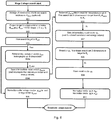
Figure 8 is a flow chart illustration of an example embodiment of astage 2 shape search flow. -
Figure 9 shows example results in terms of spectral distortion for 38 bit quantization of the envelope representation coefficients. -
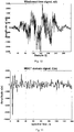
Figure 10 shows an example of a time domain signal. -
Figure 11 shows an example of an MDCT domain signal of the time signal inFigure 10 . -
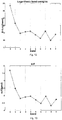
Figure 12 shows logarithmic band energies of the MDCT domain signal inFigure 11 . -
Figure 13 shows envelope representation coefficients of the logarithmic band energies inFigure 12 . -
Figure 14 illustrates an example of an encoder with gain and shape search in a transformed domain. -
Figure 15 illustrates an example of a decoder. -
Figure 16 shows a block diagram illustrating an example embodiment of an encoder. -
Figure 17 shows a block diagram illustrating another example embodiment of an encoder. -
Figure 18 shows a block diagram illustrating an example of a decoder. -
Figure 19 shows a block diagram illustrating another example of a decoder. - The inventive concept will now be described more fully hereinafter with reference to the accompanying drawings, in which certain embodiments of the inventive concept are shown. This inventive concept may, however, be embodied in many different forms and should not be construed as limited to the embodiments set forth herein; rather, these embodiments are provided by way of example so that this disclosure will be thorough and complete, and will fully convey the scope of the inventive concept, as defined by the claims, to those skilled in the art. Like numbers refer to like elements throughout the description. The figures are schematic and simplified for clarity, and they merely show details for the understanding of the embodiments presented herein, while other details have been left out.
-
Figure 1 shows acommunication network 100 comprising a transmittingunit 10 and areceiving unit 20. The transmittingunit 10 is operatively connected to thereceiving unit 20 via a communication channel 30. The communication channel 30 may be a direct connection or an indirect connection via one or more routers or switches. The communication channel 30 may be through a wireline connection, e.g. via one or more optical cables or metallic cables, or through a wireless connection, e.g. a direct wireless connection or a connection via a wireless network comprising more than one link. The transmittingunit 10 comprises anencoder 1600. Thereceiving unit 20 comprises adecoder 1800. -
Figure 2 depicts an exemplarywireless communications network 100 in which embodiments herein may be implemented. Thewireless communications network 100 may be a wireless communications network such as an LTE (Long Term Evolution), LTE-Advanced, Next Evolution, WCDMA (Wideband Code Division Multiple Access), GSM/EDGE (Global System for Mobile communications / Enhanced Data rates for GSM Evolution), UMTS (Universal Mobile Telecommunication System) or WiFi (Wireless Fidelity), or any other similar cellular network or system. - The
wireless communications network 100 comprises anetwork node 110. Thenetwork node 110 serves at least onecell 112. Thenetwork node 110 may be a base station, a radio base station, a nodeB, an eNodeB, a Home Node B, a Home eNode B or any other network unit capable of communicating with a wireless device within thecell 112 served by the network node depending e.g. on the radio access technology and terminology used. The network node may also be a base station controller, a network controller, a relay node, a repeater, an access point, a radio access point, a Remote Radio Unit, RRU, or a Remote Radio Head, RRH. - In
Figure 2 , awireless device 121 is located within thefirst cell 112. Thedevice 121 is configured to communicate within thewireless communications network 100 via thenetwork node 110 over a radio link, also called wireless communication channel, when present in thecell 112 served by thenetwork node 110. Thewireless device 121 may e.g. be any kind of wireless device such as a mobile phone, cellular phone, Personal Digital Assistants, PDA, a smart phone, tablet, sensor equipped with wireless communication abilities, Laptop Mounted Equipment, LME, e.g. USB, Laptop Embedded Equipment, LEE, Machine Type Communication, MTC, device, Machine to Machine, M2M, device, cordless phone, e.g. DECT (Digital Enhanced Cordless Telecommunications) phone, or Customer Premises Equipment, CPEs, etc. In embodiments herein, the mentionedencoder 1600 may be situated in thenetwork node 110 and the mentioneddecoder 1800 may be situated in thewireless device 121, or theencoder 1600 may be situated in thewireless device 121 and thedecoder 1800 may be situated in thenetwork node 110. - Embodiments described herein may also be implemented in a short-range radio wireless communication network such as a Bluetooth based network. In a short-range radio wireless communication network communication may be performed between different short-range radio communication enabled communication devices, which may have a relation such as the relation between an access point/base station and a wireless device. However, the short-range radio enabled communication devices may also be two wireless devices communicating directly with each other, leaving the cellular network discussion of
Figure 2 obsolete.Figure 3 shows anexemplary communication network 100 comprising a first and a second short-range radio enabledcommunication devices encoder 1600 may be situated in the first short-range radio enabledcommunication device 131 and the mentioneddecoder 1800 may be situated in the second short-range radio enabledcommunication device 132, or vice versa. Naturally both communication devices comprise an encoder as well as a decoder to enable two-way communication. - Alternatively, the communication network may be a wireline communication network.
- As part of the developing of the embodiments described herein, a problem will first be identified and discussed.
- When transmitting envelope representation coefficients from a transmitting unit comprising an encoder to a receiving unit comprising a decoder there is an interest to achieve a better compression technique, requiring low bandwidth for transmitting the signal and low computational complexity at the encoder and the decoder.
- According to one embodiment, such a problem may be solved by a method performed by an encoder of a communication system for handling input envelope representation coefficients as presented above.
-
Figure 4 is an illustrated example of actions or operations that may be taken or performed by an encoder, or by a transmitting unit comprising the encoder. In the disclosure, the "encoder" may correspond to "a transmitting unit comprising an encoder". The method of the example shown inFigure 4 may comprise one or more of the following actions:
Action 202. Quantize the input envelope representation coefficients using a first number of bits. -
Action 204. Determine envelope representation residual coefficients as first compressed envelope representation coefficients subtracted from the input envelope representation coefficients. -
Action 206. Transform the envelope representation residual coefficients into a warped domain so as to obtain transformed envelope representation residual coefficients. -
Action 208. Apply at least one of a plurality of gain-shape coding schemes on the transformed envelope representation residual coefficients in order to achieve gain-shape coded envelope representation residual coefficients, where the plurality of gain-shape coding schemes have mutually different trade-offs in one or more of gain resolution and shape resolution for one or more of the transformed envelope representation residual coefficients. -
Action 210. Transmit, over a communication channel to a decoder, a representation of the first compressed envelope representation coefficients, the gain-shape coded envelope representation residual coefficients, and information on the at least one applied gain-shape coding scheme. - According to one embodiment, such a problem may be solved by a method performed by an decoder of a communication system for handling envelope representation residual coefficients as presented above.
-
Figure 5 is an illustrated example of actions or operations that may be taken or performed by a decoder, or by a receiving unit comprising the decoder. In the disclosure, the "decoder" may correspond to "a receiving unit comprising a decoder". The method of the example shown inFigure 5 may comprise one or more of the following actions:
Action 301. Receive, over a communication channel from an encoder (1600), a representation of first compressed envelope representation coefficients, gain-shape coded envelope representation residual coefficients, and information on at least one applied gain-shape coding scheme, applied by the encoder. - Action 302. Receive, over the communication channel and from the encoder, the first number of bits used at a quantizer of the encoder.
-
Action 304. Apply at least one of a plurality of gain-shape decoding schemes on the received gain-shape coded envelope representation residual coefficients according to the received information on at least one applied gain-shape coding scheme, in order to achieve envelope representation residual coefficients, where the plurality of gain-shape decoding schemes have mutually different trade-offs in one or more of gain resolution and shape resolution for one or more of the gain-shape coded envelope representation residual coefficients. -
Action 306. Transform the envelope representation residual coefficients from a warped domain into an envelope representation original domain so as to obtain transformed envelope representation residual coefficients. -
Action 307. De-the quantize envelope representation coefficients using a first number of bits corresponding to the number of bits used for quantizing envelope representation coefficients at a quantizer of the encoder. -
Action 308. Determine envelope representation coefficients as the transformed envelope representation residual coefficients added with the received first compressed envelope representation coefficients. - According to some embodiments, the encoder performs the following actions:
The encoder applies a low bit rate first stage quantizer to the mean removed envelope representation coefficients, resulting in envelope representation residual coefficients. A lower bitrate requires smaller storage than a bitrate that is higher than the low bitrate. The mean removed envelope representation coefficients are input envelope representation coefficients with the mean value removed. - The encoder transforms the envelope representation residual coefficients to a warped domain (e.g applying Hadamard transform, Rotated DCT transform, or DCT transform.
- The encoder selectively applies at least one of a plurality of submode gain-shape coding schemes of the transformed envelope representation residual coefficients, where the submode schemes have different trade-offs in gain resolution and/or resolution for the shape of the coefficients (i.e. across the transformed envelope representation residual coefficients).
- The gain-shape submodes may use different resolution (in bits/coefficient) for different subsets. Examples of subsets {A/B}: {even+last}/{odd-last} Hadamard coefficients, DCT{0-9} and DCT{10-15}. An outlier mode may have one single full set of all the coefficients in the residual, whereas the regular mode may have several, or restricted, subsets, covering different dimensions with differing resolutions (bits/coefficient).
- In some examples, the submode scheme selection is made by a combination of low complex Pyramid Vector Quantizer-, PVQ-projection and shape fine search selection followed by an optional global mean square error, MSE, optimization. The MSE optimization is global in the sense that both gain and shape and all submodes are evaluated. This saves average complexity. The action results in a submode index and possibly a gain codeword, and shape code word(s) for the selected submode. The selectively applying may be realized by searching an initial outlier submode and subsequently a non-outlier mode.
- In some examples the gain-shape sub-mode selection is made by a combination of low complex Pyramid VQ (PVQ) shape fine search selection and then an optional global (mean square error) MSE optimization(global in the sense that both gain and shape and all submodes are evaluated). This saves average complexity and results in a shape-gain submode index j and possibly a gain codeword i, and shape code word(s) for the selected shape-gain submode j.
- In some examples the encoder searches an initial outlier submode and eventually a non-outlier mode.
- In some examples the encoder sends first stage VQ codewords over the channel to the decoder.
- In some examples the encoder sends high level submode-information over the channel to the decoder.
- In some examples the encoder combines gain codeword(s) with the shape index and send these over the channel to the decoder, if required by the selected gain-shape submode j.
- In some examples the shape PVQ codeword(s) are indexed, optionally combined with a part of the gain codeword and/or a part of the submode index by the encoder, and sent by the encoder over the channel to the decoder.
- By one or more of the embodiments of the invention one or more of the following advantages may be achieved:
Very low complexity can be achieved. - The application of a structured (energy compacting) transform allows for a strongly reduced first stage VQ. For example, the first stage VQ may be reduced to 25% of its original codebook size decreasing both Table ROM (Read Only Memory) and first stage search complexity. E.g. from R=0.875 bits/coefficient to R=0.625 bits per coefficient. E.g. with
dimensions 8 the bit rate can be dropped from 8*.875=7 bits to 8*.625=5 bits, which corresponds to a drop from 128 vectors to 32 vectors ofdimension 8. - The structured PVQ based sub-modes may be searched with an extended (low complex) linear search, even though there are several gain-shape combination sub-modes for the envelope representation coefficients available.
- The structured PVQ based sub-modes may be optimized to handle both outliers, where outliers are the envelope representation residual coefficients with an atypical high and low energy, and also handle non-outlier target vectors with sufficient resolution.
- In the following, an embodiment is presented. The proposed method requires as input a vector of envelope representation coefficients.
-
Figure 10 depicts an example of a time domain signal s(t). The example shown is 20 ms of a 16 kHz sampled signal. In general terms, the time signal s(t) is transformed into a frequency domain signal using the known MDCT transform, where component n of the frequency domain signal is denoted c(n) and is determined according to: c(n) = MDCT(s(t)).Figure 11 shows the spectral coefficients c(n) (also known as spectral lines) obtained for the time signal inFigure 10 . - In some aspects the time signal is an audio signal, such as a speech signal. An analysis window might be applied before the MDCT, see e.g. MDCT application and definition in ITU-T G.719 encoder. The spectral coefficients c(n) for n=0...(Ncoded -1), where Ncoded may be e.g. 400 coefficients from the encoder side MDCT, are in this embodiment grouped into Nbands=16 uniform bands of length Lbands = Ncoded/16. The band sizes could alternatively be logarithmic or semi- logarithmic band sizes (as in aforementioned document ITU-T G.719)). The obtained logarithmic spectral band energies enLog(band) are normalized into a vector of target scale factors scf(band) by removing the mean of all enLog(band) values:


- These target scale factors scf(band) for band=0...15 now represents an approximation of the mean level normalized Root Mean Square (RMS) shape for the spectral envelope of the original time domain input signal s(t).
Figure 12 shows the logarithmic spectral band energies enLog(band) as obtained from the spectral coefficients c(n) according to Equation (1).Figure 13 shows the scale factors scf(n) as obtained from the logarithmic spectral band energies enLog(band) according to Equation (2). - The target scale factors scf(n) as obtained according the above are quantized using a two-stage vector quantizer employing a total of 38 bits (R = 2.375 bits/coefficient). The first stage is a 10 bit split VQ and the second stage is a low complex algorithmic Pyramid VQ (PVQ). To maintain low overall VQ complexity the Pyramid VQ is analyzed in a gain/shape fashion in a transformed domain, enabling an efficient shape only search, followed by a low complex total MSE evaluation in a combined gain and shape determination step. The presented VQ-scheme can typically be realized in the range of 20-60 bits without any drastic increase in complexity with increased bit rate.
-
Figure 14 schematically illustrates functional modules of an encoder employing the above disclosedstage 1 andstage 2 VQ. A complementary representation of this encoder is shown inFigure 6 . - The first stage is a split VQ employing two off-line trained stochastic codebooks LFCB and HFCB. Each codebook row has
dimension 8 and the number of codebook columns is limited to 32, requiring 5 bits for each split for transmission. The MSE distortions for the two codebooks are defined as follows:

- The best index for the low frequency split is found (
module 601; SCF VQ-stage 1 short/low complexity search) according to:
- The best index for the high frequency split is found (
module 601; SCF VQ-stage 1 short/low complexity search) according to:
- The first stage vector is composed as:


- The first stage residual signal is calculated (module 602) as:

- Reference is made to
Figure 8 illustrating an example embodiment of astage 2 shape search flow with actions 801-810: - 801: Arrange r1 dimensions into linear search sections in r1 /inear (optional)
- 802: Project target to subpyramid at or below Koutl (e.g. K outl = K for shape j=2 or j=3)
- 803: Fine search target to K outl
- 804a: Remove any pulses in vector youtl belonging to set B dimensions
- 804b: Save intermediate result vector youtl,A (and recompute the related correlation and energy values)
- 805: Normalize outlier integer vector youtl to unit energy vector xq,outl
- 806: Based on youtl A shape result for dimensions in set A. Fine search set A dimensions in target from K 1- K outl,A to K1
- 807: Save intermediate result vector y1 (and its related correlation and energy values)
- 808: Based on y1 , fine shape search set B dimensions in target to KB
- 809: Save result vector y0
- 810: Normalize vector y1 to xq,1 , and normalize vector y0 to xq,0 .
- The corresponding modules in
Figure 6 are module 611(overall direction), module 612 (outlier shapes), module 613 (regular shapes), wheremodule 611implements actions 801 through 810, andmodule 612 implements toactions action 803 is run first with j =3 and then with j =2, and then thenormalization action 805 is run for each j ) asmodule 612 results in two outlier vectors). - On a high level the overall mean square error that is minimized(616) by the second stage is:

length 16. The shapeind, gainind, unitShapeIdxs indices results in a total of 228 possible gain-shape combinations, the target of the second stage search is to find the set of indices that results in a minimum dMSE distortion value. InFigure 6 this overall gain-shape MSE minimization and analysis is implemented by the normalizedshape selector module 614, the adjustmentgain application module 615, thesubtraction module 618 and theMSE minimization module 616. TheMSE minimization module 616 as depicted inFigure 6 may also include varying the shapes yj , (a unit energy normalized xj , would be xq,shape ,). This general error minimization loop indicated inFigure 6 and byEquation 10 indicates that the MSE error is evaluated in the original scale factor domain, however given that the implemented analysis transform and synthesis transform is of high enough numerical precision the gain-shape MSE optimization may preferably be made in the transformed scale factor domain (See Equation 11,Figure 14 ) to save encoder side processing complexity. - The second stage employs a 16-dimensional DCT-rotation using a 16-by-16 matrix D. The matrix D has been determined off-line for efficient scale factor quantization, it has the property that DT.D = I, where / is the identity matrix. To reduce the encoder side search complexity the reverse (i.e., analysis) transform D (i.e. DCT) may be used prior to the shape and gain determination, while on the decoder side only the forward(synthesis) transform DT (i.e. IDCT) is required. The coefficients of the full D rotation matrix are listed below. It should be noted that the conventional DCT() and IDCT() functions could be used to realize these transformations. Possible alternatives that also are able to handle a mean value component in the residual signal, are to use e.g the Hadamard transform with very low processing and storage requirements or even a trained Rotation Matrix. In
Figure 6 the move of a candidate signal from the transformed scale factor domain to the original scale factor domain is implemented by thesynthesis transform module 617.Figure 14 shows how the MSE-shape and gain search is preferably moved to the transformed domain by the analysis transform inmodule 1402, this is also explicitly shown in Equation 11. - There are four different 16-dimensional unit energy normalized shape candidates evaluated, where the normalization is always performed over 16 coefficients. The pulse configurations for two sets (denoted A and B) of scale factors for each candidate shape index( j ) are given in Table 1.
Table 1: Scale factor VQ second stage shape candidate pulse configurations Shape index (j) Shape name Scale factor set A Scale factor set B Pulse configuration, Set A, PVQ(NA, KA) Pulse configuration, Set B, PVQ(NB, KB) 0 "regular" {0,1,2,3,4,5,6, 7,8,9} {10,11,12,13,14, 15} PVQ(10, 10) PVQ(6, 1) 1 "regular_lf" {0,1,2,3,4,5,6, 7,8,9} {10,11,12,13,14, 15} PVQ(10, 10) Zeroed 2 'outlier_near' {0,1,2,3,4,5,6, 7,8,9, 10,11,12,13,14 ,15} Empty set PVQ(16, 8) Empty 3 'outlier_far' {0,1,2,3,4,5,6, 7,8,9, 10,11,12,13,14 ,15} Empty set PVQ(16, 6) Empty - Shape index j=0 pulse configuration is a hybrid PVQ shape configuration, with KA =10 over NA =10 scale factors and KA =1 over the remaining NB =6 scale factors. For
shape index 0, it the two sets of unit pulses are unit energy normalized over the full target dimension N=NA + NB =16, even though the PVQ integer pulse and sign enumeration is performed separately for each scale factor set. - The shape search target preparation consists of a 16x16 dimensional matrix analysis rotation (a DCT implemented using matrix D) as follows:

- The goal of a generic PVQ(N, K) shape search procedure is to find the best normalized vector xq(n). In vector notation, xq(n) is defined as:


- I.e. Xq is the unit energy normalized integer vector y , a deterministic point on the unit energy hypersphere. The best integer y vector is the one minimizing the mean squared shape error between the second stage target vector t2rot(n) = x(n) and the normalized quantized output vector xq . The shape search is achieved by minimizing the following
distortion:
- Equivalently, by squaring numerator and denominator, by maximizing the quotient QPVQ-shape :


- The best position nbest for the k'th unit pulse, is iteratively updated by increasing nc from 0 to N-1:

- To avoid division operations (which might be especially important in fixed point arithmetic) the QPVQ-shape maximization update decision may be performed using a cross-multiplication of a saved best squared correlation numerator bestCorrSq so far and the saved best energy denominator bestEn so far:

- The iterative maximization of Q PVQ-shape(k, nc) may start from a zero number of initially placed unit pulses (ystart(n) = 0, for n=0...15) or alternatively from a low cost pre-placement number of unit pulses based on an projection to a integer valued point below the K'th-pyramid's surface, with a guaranteed undershoot of unit pulses in the target L1 norm K. Such a projection may be made as follows:


- A projection to K (on the PVQ(N,K) pyramids surface) might also be used. It numerical precision issues result in a point above the pyramids surface, a new valid projection at or below the surface needs to be performed, or alternatively unit pulses are removed until the surface of the pyramid is reached.
- For shape j=0, the set B positions only contain one single non-stacked unit pulse with a fixed energy contribution. This means that the search for the single pulse in set B may be simplified to search only for the maximum absolute value in the six set B locations.
- Four signed integer pulse configurations vectors yj are established by using distortion measure dPVQ-shape and then their corresponding unit energy shape vectors xq,j are computed according to Equation (12). As each total pulse configuration yj always spans 16 coefficients, the energy normalization is always performed over
dimension 16, even though two shorter sets are used for enumeration of the y0 integer vector. - An efficient overall unit pulse search (for all four shape candidates) may be achieved by searching the shapes in the order from shape j=3 to shape j=0, by making a first projection to a point on or below the pyramid K=6, and then sequentially add unit pulses and save intermediate shape results until K is correct for each of the shape candidates with a higher number of unit pulses K. Note that as the regular set A shapes j=0, 1 spans over different allowed scale factor regions than the two outlier shapes (j=2, 3), the search start pulse configuration for the two regular shapes is handled by removing any unit pulses which are not possible to index in the regular shape sets A (for j=0,1). As the pulse search is performed in the all positive orthant, a final step of setting the signs of the non-zero entries in yj (n) based on the corresponding sign of the target vector x(n) is performed.
- An example of a search procedure corresponding to the above PVQ search strategy for the described PVQ based shapes is summarized in Table 2.
Table 2: Informational example of PVQ search strategy for the described PVQ based shapes. Search step Related shape index (=j) Description of search step Resulting integer vector 1 3 Project to or below pyramid N=16, K=6 y 3,start2 3 Add unit pulses until you reach L1norm= K=6 over N=16 samples y3, = y 2,start3 2 Add unit pulses until you reach L1norm= K=8 over N=16 samples y2, = y 1,pre-start4 1 Remove any unit pulses in y1,pre-start that are not part of set A to yield y1, start y1, start 5 1 Update energy eny and correlation corrxy terms to reflect the pulses present in y1, start y1, start (unchanged) 6 1 Add unit pulses until you reach L1norm= K=10 over N=10 samples (in set A) y1, = y 0, start7 0 Add unit pulses to y0,start until you reach L 1norm= K=1 over N=6 samples (in set B) y 0 8 3,2,1,0 Add signs to non zero positions of each yj vector from the target vector x y3, y2, y1, y0 9 3,2,1,0 Unit energy normalize each yj vector to candidate vector xq,j xq,3, xq,2, xq,1, xq,0 - An example of potentially available integer vectors yj and unit energy normalized vectors xq,j, after the PVQ search are summarized in Table 3.
Table 3: Informational example of potentially available integer vectors yj and unit energy normalized vectors xq,j, after the PVQ search. Shape index (=j) Example Integer vector yj Corresponding unit energy normalized vector xq,j (NB! shown in very low precision here) 0 yo = [-10,0,0,0,0,0,0,0, 0,0, 0,0,0,0,0, 1] xq,0 = [-0.995,0,0,0,0,0,0,0, 0,0,0, 0,0,0,0,0.100] 1 y1 =[0,0,0,0,0,0, 0,0, 0, 10,0,0,0,0,0,0] xq,1 =[0,0,0,0,0,0,0,0, 0,1.0, 0,0,0,0,0,07 2 y2 =[0,0,0,0,0,0,0,0, 0,1,0,0,0,0,0,-7] xq,2 =[0,0,0,0,0,0,0,0, 0,0.141,0,0,0,0,0,-0.9901 3 y3 = [0,0,0,0,0,0,0,0, 0,0, -1, 1,-1, 1,-1, 1 ] xq,3 = [0,0,0,0,0,0,0,0, 0,0,-0.408,0.408,-0.408,0.408,-0.408,0.4081 - There are four different adjustment gain candidate sets, one set corresponding to each overall shape candidate j. The adjustment gain configuration for each of the shapes are given in Table 4
Table 4: Scale factor VQ Second Stage Adjustment Gain sets including a global common gain factor of 2.5 Gain set index (same as shape index =j) Corresponding Shape name Number of gain levels Adjustment Gain set values ( Ggain_index, j ) Start adjustment gain index Gminindj End adjustment gain index Gmaxindj 0 'regular' 2 2.5* {0.87, 1.18} = {2.175, 2.95 } 0 1 1 "regular_lf" 4 2.5* {0.61, 1.47, 1.74, 2.05} 0 3 2 "outlier_near" 4 2.5* {0.69, 0.89, 1.10, 1.45 } 0 3 3 "outlier_far" 8 2.5* {0.42, 0.49, 0.58,0.80, 1.00, 1.25, 1.65, 1.94 } 0 7 - The best possible shape and gain is determined among the possible shape candidates and each corresponding gain set. To minimize complexity the MSE versus the target may be evaluated in the rotated domain, i.e. the same domain as the shape search was performed in:

- Out of the total 18(2+4+4+8) possible gain-shape combinations, the shape_index(=j) and adjustment gain index gain_index(=i) that results in the minimum MSE are selected for subsequent enumeration and multiplexing:

- The pulse configuration(s) of the selected shape are enumerated using an efficient scheme which separates each PVQ(N, K) pulse configuration into two short codewords; a leading sign index bit and an integer MPVQ-index codeword. The MPVQ-index bit-space is typically fractional (i.e. a non-power of 2 total number of pulse configurations). In
Figure 6 the enumeration of the selected integer vector yj into leading sign index bit LS_indA and MPVQ-index idxA (and additionally for shape j=0, into leading sign index bit LS_indB and MPVQ-index idxB) is implemented by the MPVQ-enumeration module 621. - The largest sized MPVQ integer shape index (j=2, "outlier_near") fits within a 24 bit unsigned word, enabling fast implementations of MPVQ enumeration and de-enumeration on platforms supporting unsigned integer arithmetic of 24 bits or higher.
- The enumeration scheme uses an indexing offsets table A(n, k) which may be found as tabled unsigned integer values below. The offset values in A (dimension n, L1-norm k) are defined recursively as:

- The actual enumeration of a signed integer vector y(=vec_in) with an L1 norm of K(=k_val_in) over dimension N (=dim_in), into an MPVQ shape index index an and a leading sign index lead_sign_ind is shown in pseudo-code below:


- MPVQ enumeration calls for a selected shape (j) are summarized in Table 5:
Table 5: Scale factor VQ second stage shape enumeration of integer vector yj into leading signs indices and MPVQ shape indices for each possible selected shape index j. Shape index (j) Shape name Scale factor set A enumeration Scale factor set B enumeration 0 "regular" [LS_indA, idxA] = MPVQenum(10, 10,y0) z(10-n) = y0(n), for n=10...15 [LS_indB, idxB] = MPVQenum(6,1,z); 1 'regular_lf' [LS_indA, idxA ] = MPVQenum(10, 10,y1 ) n/a 2 "outlier_near" [LS_indA, idxA] = MPVQenum(16, 8, y 2) n/a 3 "outlier_far" [LS_indA, idxA ] = MPVQdeum(16, 6, y 3) n/a - The
stage 1 indices are multiplexed in the following order: ind_LF (5 bits) followed by ind_HF(5 bits). - To efficiently use the available total bit space for the scale factor quantizer (38 bits), in combination with the fractional sized MPVQ-indices, the shape index j, the second stage shape codewords and potentially an LSB of the gain codeword are jointly encoded. The overall parameter encoding order for the second stage multiplexing components is shown in Table 6.
Table 6: Multiplexing order and parameters for the second stage. scale factor - VQ Stage 2 Parameter Multiplexing order Stage 2 parameter description Parameter 0 stage 2 submode bitj>>1, (as an MSB submode bit) 1 Adjustment gain or MSBs of the adjustment gain i, (the actual gain index), for even(j) (or i>>1; for odd (j) 2 leading sign of shape in set A LeadSignA 3 a joint shape index(for set A and set B) and possibly a submode LSB-bit and a gain LSB bit. Joint composition of : (indexshapeA, , LeadSignB, indexshapeB, LSBsubmode, L The LSB submode bit is encoded as a specific bitspace section inside the overall joint shape codeword indexjoint. - In the multiplexing of leading signs LeadSignA and/or LeadSignB, each leading sign is multiplexed as 1 if the leading sign is negative and multiplexed as a 0 if the leading sign is positive. Table 7 shows submode bit values, sizes of the various second stage MPVQ shape indices, and the adjustment gain separation sections for each shape index (j).
Table 7: Submode bit values, sizes of the various second stage MPVQ shape indices, and the adjustment gain separation sections for each shape index (j). Shape index (j) Shape name MSB Submode bit value (regular/outlier) SZMPVQ Set A (excl. LeadSignA ) SZMPVQ Set B (excl. LeadSignB ) Number of LSB gain index code points Adjustment gain index bit separation {MSBs, LSB} 0 "regular" 0 SZshapeA,0 = 2390004 (∼21.1886 bits) SZshapeB,0 = 6 (∼2.585 bits) 0 {1, 0} 1 'regular_lf' 0 SZshapeA,1 = SZshapeA,0 SZshapeB,1 = 1 (0 bits) 2 {1, 1} 2 "outlier_near" 1 SZshapeA,2 15158272 (∼23.8536 bits) n/a 0 {2,0} 3 "outlier_far' 1 SZshapeA,3 = 774912 (∼19.5637 bits) n/a 2 {2, 1} - For a selected shape with shape index j=0 and j=2, the selected gain index is sent without modification as index i, for gain value Gi,j , requiring 1 bit for j=0 and 2 bits for j=2.
- For a selected shape with shape index j=1 and j=3, and a selected gain value Gi,j with gain index i, the MSB part of the gain index is first sent by a removal of the LSBgain bit. That is. iMsBs = i>>1; LSBgain = i&0x1; The multiplexing of iMSBs will require 1 bit for j=1 and 2 bits for j=3. The LSBgain bit will be multiplexed into the joint index.
- In
Figure 6 the joint index composition based on the selected shape j and the selected gain index i and the enumerated leading sign index bit LS_indA and MPVQ-index idxA (and for shape j=0, leading sign index bit LS_indB and MPVQ-index idxB) is performed by the jointindex composition module 622, and further the result of the joint composition is sent to theencoder multiplexor module 623 for subsequent transmission to the decoder. - Composition of the joint index for a selected shape index of j=0 ('regular') is determined as:

- Composition of the joint index for a selected shape index of j=1 ('regular_lf') is determined as:

- Composition of the joint index for a selected shape index of j=2 ('outlier_near') is determined as:

- Composition of the joint index for a selected shape index of j=3 ('outlier_far')

- The quantized first stage vector st1, the quantized second stage unit energy shape vector xq,j and the quantized adjustment gain Gi,j (with gain index i) are used to establish the quantized scale factor vector scfQ(n) as follows:


- In equation (30, the xq,j (n) · DT vector times matrix multiplication realizes the IDCT synthesis transform. Even though this (Equations 30 and 31) quantized scale factor generation takes place on the encoder side, the corresponding steps are performed the same way in the decoder, see
Figure 7 modules 702; SCF VQ-stage 1 contribution, 706; Inverse warping/ transform, the adjustment gain inmodule 707, and the addition inmodule 708. - The quantized scale factor vector scfQ(n) is now used to scale/normalize the MDCT coefficients c(n) into cnorm(n) as follows:

- The normalized coefficients cnorm(n) may be quantized using a logarithmic PCM quantizer, like ITU-T G.711, where G.711 is defined for using 8 bits per coefficient, into normQ(n) for n=(0..Ncoded-1). And G711 mu-law may handle a dynamic range of 14 bits.
- The resulting residual spectrum parameter bytes spec(n) for n=(0...Ncoded-1) are forwarded on the transport channel, where each spec(n) is a G.711 8 bit index.
- In some aspects the decoder performs the following steps. A set of 16 quantized scale factors is first decoded as described for/in the encoder. These quantized scale factors are the same as the quantized scale factors obtained in the encoder. The quantized scale factors are then used to shape the received MDCT normalized spectrum coefficient as described below.
-
Figure 15 schematically illustrates functional modules of a corresponding decoder for the encoder employing the above disclosedstage 1 andstage 2 VQ. A complementary representation of this decoder is shown inFigure 7 . - The first stage parameters are decoded, in
Figure 7 this is performed by thedemultiplexor module 701; and inFigure 14 this is performed by the bitstream demultiplexor module 1501 as follows:
ind_LF = read_indice(5); /*stagel LF 5 bits */ ind_HF = read_indice(5); /*stagel HF 5 bits */


 shape_j = (submodeMSB<<1) + submodeLSB;
 j = shape_j;
 i = G_ind;


| Shape index (j) | Shape name | Scale factor set A de-enumeration | Scale factor set B de-enumeration (or initialization) |
| 0 | "regular" | MPVQdeenum(10, 10,y0 , LS_indA, idxA) | MPVQdeenum(6,1, z, LS_indB, idxB); |
| yo(n) = z(n-10), for n=10 ...15 | |||
| 1 | 'regular_lf' | MPVQdeenum(10, 10, y1, LS_indA, idxA) | y1(n) = 0, for n=10 ...15 |
| 2 | 'outlier_near' | MPVQdeenum(16, 8, y2 , LS_indA, idxA) | n/a |
| 3 | 'outlier_far' | MPVQdeenum(16, 6, y3, LS_indA, idxA) | n/a |


 unsigned int A[1+16][1+10]=
 /* k=0,k=1,k=2, ... , k=10*/
 /* n= 0 */ 0U,1U,1U, 1U, 1U, 1U, 1U, 1U, 1U, 1U, 1U,
 /* n= 1 */ 0U,1U,3U. 5U, 7U, 9U, 11U, 13U, 15U, 17U, 19U,
 /* n= 2 */ 0U,1U,5U, 13U, 25U, 41U, 61U, 85U, 113U, 145U, 181U,
 /* n= 3 */ 0U,1U,7U, 25U, 63U, 129U, 231U, 377U, 575U, 833U, 1159U,
 /* n= 4 */ 0U,1U,9U. 41U, 129U, 321U, 681U, 1289U, 2241U, 3649U, 5641U,
 /* n= 5 */ 0U,1U,11U, 61U, 231U, 681U, 1683U, 3653U, 7183U, 13073U, 22363U,
 /* n= 6 */ 0U,1U,13U, 85U, 377U, 1289U, 3653U, 8989U, 19825U, 40081U, 75517U,
 /* n= 7 */ 0U,1U,15U, 113U, 575U, 2241U, 7183U, 19825U, 48639U, 108545U, 224143U,
 /* n= 8 */ 0U,1U,17U, 145U, 833U, 3649U, 13073U, 40081U, 108545U, 265729U, 598417U,
 /* n= 9 */ 0U,1U,19U, 181U, 1159U, 5641U, 22363U, 75517U, 224143U, 598417U, 1462563U,
 /* n=10 */ 0U,1U,21U, 221U, 1561U, 8361U, 36365U, 134245U, 433905U, 1256465U, 3317445U,
 /* n=11 */ 0U,1U,23U, 265U, 2047U, 11969U, 56695U, 227305U, 795455U, 2485825U, 7059735U,
 /* n=12 */ 0U,1U,25U, 313U, 2625U, 16641U, 85305U, 369305U, 1392065U, 4673345U, 14218905U,
 /* n=13 */ 0U,1U,27U, 365U, 3303U, 22569U, 124515U, 579125U, 2340495U, 8405905U, 27298155U,
 /* n=14 */ 0U,1U,29U, 421U, 4089U, 29961U, 177045U, 880685U, 3800305U, 14546705U, 50250765U,
 /* n=15 */ 0U,1U,31U, 481U, 4991U, 39041U, 246047U, 1303777U, 5984767U, 24331777U,
 89129247U};


- LSF
- Line Spectral Frequencies
- LSP
- Line Spectral Pairs
- ISP
- Immittance Spectral Pairs
- ISF
- Immittance Spectral Frequencies
- VQ
- Vector Quantizer
- MS-SVQ
- MultiStage Split Vector Quantizer
- PVQ
- Pyramid VQ
- NPVQ
- Number of PVQ indices
- MPVQ
- sign Modular PVQ enumeration scheme
- MSE
- Mean Square Error
- RMS
- Root Mean Square
- WMSE
- Weighted MSE
- LSB
- Least Significant Bit
- MSB
- Most Significant Bit
- DCT
- Discrete Cosine Transform
- IDCT
- Inverse Discrete Cosine Transform
- RDCT
- Rotated (ACF based) DCT
- LOG2
-
Base 2 logarithm - SD
- Spectral Distortion
- EVS
- Enhanced Voice Service
- WB
- Wideband (typically an audio signal sampled at 16kHz)
- WMOPS
- Weighted Million Operations per Second
- WC-WMOPS
- Worst Case WMOPS
- AMR-WB
- Adaptive Multi-Rate Wide Band
- DSP
- Digital Signal Processor
- TCQ
- Trellis Coded Quantization
- MUX
- MUltipleXor (multiplexing unit)
- DEMUX
- DE-MUltipleXor (de-multiplexing unit)
- ARE
- Arithmetic/Range Encoder
- ARD
- Arithmetic/Range Decoder
Claims (21)
- A method performed by an encoder (1600) of a communication system (100) for handling input envelope representation coefficients, the method comprising:determining (204) envelope representation residual coefficients as first compressed envelope representation coefficients subtracted from the input envelope representation coefficients;transforming (206) the envelope representation residual coefficients into a warped domain so as to obtain transformed envelope representation residual coefficients;applying (208) at least one of a plurality of gain-shape coding schemes on the transformed envelope representation residual coefficients in order to achieve gain-shape coded envelope representation residual coefficients, where the plurality of gain-shape coding schemes have mutually different trade-offs in one or more of gain resolution and shape resolution for one or more of the transformed envelope representation residual coefficients; andtransmitting (210), over a communication channel to a decoder, a representation of the first compressed envelope representation coefficients, the gain-shape coded envelope representation residual coefficients, and information on the at least one applied gain-shape coding scheme.
- Method according to claim 1, further comprising:quantizing (202) the input envelope representation coefficients using a first number of bits,and wherein the determining (204) of envelope representation residual coefficients comprises subtracting the quantized envelope representation coefficients from the input envelope representation coefficients, and the transmitted first compressed envelope representation coefficients are the quantized envelope representation coefficients.
- Method according to any of the preceding claims, wherein the applying (208) at least of one of a plurality of gain-shape coding schemes on the transformed envelope representation residual coefficients comprises selectively applying the at least one of the plurality of gain-shape coding schemes.
- Method according to claim 3, wherein the selection in the selectively applying (208) of the at least one of the plurality of gain-shape coding schemes is performed by a combination of a PVQ shape projection and a shape fine search to reach a first PVQ pyramid code point over available dimensions on a per envelope representation residual coefficient basis.
- Method according to claim 3, wherein the selection in the selectively applying (208) of the at least one of the plurality of gain-shape coding schemes is performed by a combination of a PVQ shape projection and a shape fine search to reach a first PVQ pyramid codepoint over available dimensions followed by another shape fine search to reach a second PVQ pyramid code point within a restricted set of dimensions.
- Method according to any of the preceding claims, wherein at least some of the plurality of gain-shape coding schemes use mutually different bit resolutions for different subsets of envelope representation residual coefficients.
- Method according to any of the preceding claims, wherein the input envelope representation coefficients are mean removed envelope representation coefficients.
- Method according to any of the preceding claims, wherein the applying (208) at least of one of a plurality of gain-shape coding schemes on the transformed envelope representation residual coefficients comprises applying a two-stage VQ.
- Method according to claim 8, wherein the two-stage VQ comprises a first stage split VQ and a second stage PVQ.
- Method according to claim 9, wherein the split VQ employs two off-line trained stochastic codebooks.
- Method according to claim 10, wherein the two off-line trained stochastic codebooks are not larger than half the size of codebooks used during the second stage PVQ.
- Method according to claim 9, wherein the PVQ employs application of a DCT-rotation matrix, application of a shape search, application of adjustment gain and submode quantization, and application of shape enumeration.
- Method according to claim 12, wherein the two-stage VQ employs a total of whole 38 bits.
- Method according to any of the preceding claims, wherein an integer bit space for gain-shape multiplexing is used by sectioning a joint shape codeword into several subsections, and where a specific subsection indicates submode least significant bit, a gain least significant bit, or an additional shape codeword.
- Method according to any of the preceding claims, wherein the representation is defined by indices to codebooks.
- Method according to any of the preceding claims, wherein the representation is defined by the first compressed envelope representation coefficients, the gain-shape coded envelope representation residual coefficients, and the information on at least one applied gain-shape coding scheme themselves.
- Method according to any of the preceding claims, wherein the envelope representation coefficients represent scale factors.
- Method according to any of the preceding claims, wherein the envelope representation coefficients represent an encoded audio waveform.
- An encoder (1600) of a communication system (100) for handling input envelope representation coefficients, the encoder comprising processing circuitry (1603), the processing circuitry being configured to cause the encoder (1600) to:determine envelope representation residual coefficients as first compressed envelope representation coefficients subtracted from the input envelope representation coefficients;transform the envelope representation residual coefficients into a warped domain so as to obtain transformed envelope representation residual coefficients;apply at least one of a plurality of gain-shape coding schemes on the transformed envelope representation residual coefficients in order to achieve gain-shape coded envelope representation residual coefficients, where the plurality of gain-shape coding schemes have mutually different trade-offs in one or more of gain resolution and shape resolution for one or more of the transformed envelope representation residual coefficients; andtransmit, over a communication channel to a decoder, a representation of the first compressed envelope representation coefficients, the gain-shape coded envelope representation residual coefficients, and information on the at least one applied gain-shape coding scheme.
- The encoder (1600) according to claim 19, the encoder further being configured to perform the method according to any of claims 1 to 18.
- A computer program (1605) for handling input envelope representation coefficients, the computer program comprising computer code which, when run on processing circuitry (1603) of an encoder (1600), causes the encoder (1600) to:determine (204) envelope representation residual coefficients as first compressed envelope representation coefficients subtracted from the input envelope representation coefficients;transform (206) the envelope representation residual coefficients into a warped domain so as to obtain transformed envelope representation residual coefficients;apply (208) at least one of a plurality of gain-shape coding schemes on the transformed envelope representation residual coefficients in order to achieve gain-shape coded envelope representation residual coefficients, where the plurality of gain-shape coding schemes have mutually different trade-offs in one or more of gain resolution and shape resolution for one or more of the transformed envelope representation residual coefficients; andtransmit (210), over a communication channel to a decoder, a representation of the first compressed envelope representation coefficients, the gain-shape coded envelope representation residual coefficients, and information on the at least one applied gain-shape coding scheme.
Priority Applications (2)
| Application Number | Priority Date | Filing Date | Title |
|---|---|---|---|
| EP20177960.0A EP3723087A1 (en) | 2016-12-16 | 2017-12-15 | Method and encoder for handling envelope representation coefficients |
| PL17816811T PL3555885T3 (en) | 2016-12-16 | 2017-12-15 | Method and encoder for handling envelope representation coefficients |
Applications Claiming Priority (3)
| Application Number | Priority Date | Filing Date | Title |
|---|---|---|---|
| US201662435173P | 2016-12-16 | 2016-12-16 | |
| US201762583791P | 2017-11-09 | 2017-11-09 | |
| PCT/EP2017/082951 WO2018109143A1 (en) | 2016-12-16 | 2017-12-15 | Methods, encoder and decoder for handling envelope representation coefficients |
Related Child Applications (1)
| Application Number | Title | Priority Date | Filing Date |
|---|---|---|---|
| EP20177960.0A Division EP3723087A1 (en) | 2016-12-16 | 2017-12-15 | Method and encoder for handling envelope representation coefficients |
Publications (2)
| Publication Number | Publication Date |
|---|---|
| EP3555885A1 EP3555885A1 (en) | 2019-10-23 |
| EP3555885B1 true EP3555885B1 (en) | 2020-06-24 |
Family
ID=60702783
Family Applications (2)
| Application Number | Title | Priority Date | Filing Date |
|---|---|---|---|
| EP17816811.8A Active EP3555885B1 (en) | 2016-12-16 | 2017-12-15 | Method and encoder for handling envelope representation coefficients |
| EP20177960.0A Pending EP3723087A1 (en) | 2016-12-16 | 2017-12-15 | Method and encoder for handling envelope representation coefficients |
Family Applications After (1)
| Application Number | Title | Priority Date | Filing Date |
|---|---|---|---|
| EP20177960.0A Pending EP3723087A1 (en) | 2016-12-16 | 2017-12-15 | Method and encoder for handling envelope representation coefficients |
Country Status (8)
| Country | Link |
|---|---|
| US (3) | US10580422B2 (en) |
| EP (2) | EP3555885B1 (en) |
| CN (2) | CN110050304B (en) |
| ES (1) | ES2821141T3 (en) |
| MX (1) | MX2019006535A (en) |
| PL (1) | PL3555885T3 (en) |
| PT (1) | PT3555885T (en) |
| WO (1) | WO2018109143A1 (en) |
Families Citing this family (3)
| Publication number | Priority date | Publication date | Assignee | Title |
|---|---|---|---|---|
| US10950251B2 (en) * | 2018-03-05 | 2021-03-16 | Dts, Inc. | Coding of harmonic signals in transform-based audio codecs |
| US20200402523A1 (en) * | 2019-06-24 | 2020-12-24 | Qualcomm Incorporated | Psychoacoustic audio coding of ambisonic audio data |
| CN112735449B (en) * | 2020-12-30 | 2023-04-14 | 北京百瑞互联技术有限公司 | Audio coding method and device for optimizing frequency domain noise shaping |
Family Cites Families (11)
| Publication number | Priority date | Publication date | Assignee | Title |
|---|---|---|---|---|
| US7069212B2 (en) * | 2002-09-19 | 2006-06-27 | Matsushita Elecric Industrial Co., Ltd. | Audio decoding apparatus and method for band expansion with aliasing adjustment |
| KR100487719B1 (en) | 2003-03-05 | 2005-05-04 | 한국전자통신연구원 | Quantizer of LSF coefficient vector in wide-band speech coding |
| ES2358125T3 (en) * | 2005-04-01 | 2011-05-05 | Qualcomm Incorporated | PROCEDURE AND APPLIANCE FOR AN ANTIDISPERSION FILTER OF AN EXTENDED SIGNAL FOR EXCESSING THE BAND WIDTH SPEED EXCITATION. |
| KR101290622B1 (en) * | 2007-11-02 | 2013-07-29 | 후아웨이 테크놀러지 컴퍼니 리미티드 | An audio decoding method and device |
| EP2239731B1 (en) * | 2008-01-25 | 2018-10-31 | III Holdings 12, LLC | Encoding device, decoding device, and method thereof |
| CN101588182A (en) * | 2008-05-19 | 2009-11-25 | 华为技术有限公司 | Method and device for regulating vector as well as method and device for decoding regulated vector |
| EP2357649B1 (en) * | 2010-01-21 | 2012-12-19 | Electronics and Telecommunications Research Institute | Method and apparatus for decoding audio signal |
| CN102222505B (en) * | 2010-04-13 | 2012-12-19 | 中兴通讯股份有限公司 | Hierarchical audio coding and decoding methods and systems and transient signal hierarchical coding and decoding methods |
| ES2741559T3 (en) * | 2011-04-15 | 2020-02-11 | Ericsson Telefon Ab L M | Adaptive sharing of gain-form speed |
| US20200402523A1 (en) * | 2019-06-24 | 2020-12-24 | Qualcomm Incorporated | Psychoacoustic audio coding of ambisonic audio data |
| US11361776B2 (en) * | 2019-06-24 | 2022-06-14 | Qualcomm Incorporated | Coding scaled spatial components |
-
2017
- 2017-12-15 PL PL17816811T patent/PL3555885T3/en unknown
- 2017-12-15 CN CN201780075965.9A patent/CN110050304B/en active Active
- 2017-12-15 WO PCT/EP2017/082951 patent/WO2018109143A1/en unknown
- 2017-12-15 US US15/774,535 patent/US10580422B2/en active Active
- 2017-12-15 ES ES17816811T patent/ES2821141T3/en active Active
- 2017-12-15 CN CN202211569599.1A patent/CN116343804A/en active Pending
- 2017-12-15 EP EP17816811.8A patent/EP3555885B1/en active Active
- 2017-12-15 MX MX2019006535A patent/MX2019006535A/en unknown
- 2017-12-15 PT PT178168118T patent/PT3555885T/en unknown
- 2017-12-15 EP EP20177960.0A patent/EP3723087A1/en active Pending
-
2020
- 2020-02-06 US US16/783,823 patent/US11430455B2/en active Active
-
2022
- 2022-08-22 US US17/821,344 patent/US20230072546A1/en active Pending
Non-Patent Citations (1)
| Title |
|---|
| None * |
Also Published As
| Publication number | Publication date |
|---|---|
| BR112019008054A2 (en) | 2019-07-02 |
| EP3555885A1 (en) | 2019-10-23 |
| MX2019006535A (en) | 2019-08-21 |
| US10580422B2 (en) | 2020-03-03 |
| US20200176005A1 (en) | 2020-06-04 |
| WO2018109143A1 (en) | 2018-06-21 |
| US20190362730A1 (en) | 2019-11-28 |
| US20230072546A1 (en) | 2023-03-09 |
| PL3555885T3 (en) | 2021-01-11 |
| PT3555885T (en) | 2020-07-20 |
| CN110050304B (en) | 2022-11-29 |
| EP3723087A1 (en) | 2020-10-14 |
| CN110050304A (en) | 2019-07-23 |
| CN116343804A (en) | 2023-06-27 |
| US11430455B2 (en) | 2022-08-30 |
| ES2821141T3 (en) | 2021-04-23 |
Similar Documents
| Publication | Publication Date | Title |
|---|---|---|
| US20230072546A1 (en) | Methods, encoder and decoder for handling envelope representation coefficients | |
| US10841584B2 (en) | Method and apparatus for pyramid vector quantization de-indexing of audio/video sample vectors | |
| US8438020B2 (en) | Vector quantization apparatus, vector dequantization apparatus, and the methods | |
| WO2007132750A1 (en) | Lsp vector quantization device, lsp vector inverse-quantization device, and their methods | |
| WO2007114290A1 (en) | Vector quantizing device, vector dequantizing device, vector quantizing method, and vector dequantizing method | |
| EP2557566B1 (en) | Method and apparatus for processing an audio signal | |
| US20110316732A1 (en) | Vector quantization device, vector inverse-quantization device, and methods of same | |
| US20100274556A1 (en) | Vector quantizer, vector inverse quantizer, and methods therefor | |
| US20040176951A1 (en) | LSF coefficient vector quantizer for wideband speech coding | |
| EP3555886B1 (en) | Methods, encoder and decoder for handling line spectral frequency coefficients | |
| BR112019008054B1 (en) | METHODS FOR HANDLING INPUT ENVELOPE REPRESENTATION COEFFICIENTS AND RESIDUAL ENVELOPE REPRESENTATION COEFFICIENTS, ENCODER, AND, DECODER | |
| US20230238012A1 (en) | Encoding device, decoding device, encoding method, and decoding method | |
| EP4318954A1 (en) | Encoding device, decoding device, encoding method, and decoding method | |
| JPH03263100A (en) | Audio encoding and decoding device | |
| CA2991341A1 (en) | Bit error detector for an audio signal decoder | |
| EP2490217A1 (en) | Encoding device, decoding device and methods therefor | |
| CN116964944A (en) | Encoding device, decoding device, encoding method, and decoding method | |
| CN112352277A (en) | Encoding device and encoding method |
Legal Events
| Date | Code | Title | Description |
|---|---|---|---|
| STAA | Information on the status of an ep patent application or granted ep patent |
Free format text: STATUS: UNKNOWN |
|
| STAA | Information on the status of an ep patent application or granted ep patent |
Free format text: STATUS: THE INTERNATIONAL PUBLICATION HAS BEEN MADE |
|
| PUAI | Public reference made under article 153(3) epc to a published international application that has entered the european phase |
Free format text: ORIGINAL CODE: 0009012 |
|
| STAA | Information on the status of an ep patent application or granted ep patent |
Free format text: STATUS: REQUEST FOR EXAMINATION WAS MADE |
|
| 17P | Request for examination filed |
Effective date: 20190613 |
|
| AK | Designated contracting states |
Kind code of ref document: A1 Designated state(s): AL AT BE BG CH CY CZ DE DK EE ES FI FR GB GR HR HU IE IS IT LI LT LU LV MC MK MT NL NO PL PT RO RS SE SI SK SM TR |
|
| AX | Request for extension of the european patent |
Extension state: BA ME |
|
| GRAP | Despatch of communication of intention to grant a patent |
Free format text: ORIGINAL CODE: EPIDOSNIGR1 |
|
| STAA | Information on the status of an ep patent application or granted ep patent |
Free format text: STATUS: GRANT OF PATENT IS INTENDED |
|
| INTG | Intention to grant announced |
Effective date: 20200120 |
|
| DAV | Request for validation of the european patent (deleted) | ||
| DAX | Request for extension of the european patent (deleted) | ||
| GRAS | Grant fee paid |
Free format text: ORIGINAL CODE: EPIDOSNIGR3 |
|
| GRAA | (expected) grant |
Free format text: ORIGINAL CODE: 0009210 |
|
| STAA | Information on the status of an ep patent application or granted ep patent |
Free format text: STATUS: THE PATENT HAS BEEN GRANTED |
|
| AK | Designated contracting states |
Kind code of ref document: B1 Designated state(s): AL AT BE BG CH CY CZ DE DK EE ES FI FR GB GR HR HU IE IS IT LI LT LU LV MC MK MT NL NO PL PT RO RS SE SI SK SM TR |
|
| REG | Reference to a national code |
Ref country code: GB Ref legal event code: FG4D |
|
| REG | Reference to a national code |
Ref country code: CH Ref legal event code: EP |
|
| REG | Reference to a national code |
Ref country code: FI Ref legal event code: FGE |
|
| REG | Reference to a national code |
Ref country code: AT Ref legal event code: REF Ref document number: 1284687 Country of ref document: AT Kind code of ref document: T Effective date: 20200715 |
|
| REG | Reference to a national code |
Ref country code: DE Ref legal event code: R096 Ref document number: 602017018834 Country of ref document: DE |
|
| REG | Reference to a national code |
Ref country code: PT Ref legal event code: SC4A Ref document number: 3555885 Country of ref document: PT Date of ref document: 20200720 Kind code of ref document: T Free format text: AVAILABILITY OF NATIONAL TRANSLATION Effective date: 20200715 |
|
| REG | Reference to a national code |
Ref country code: IE Ref legal event code: FG4D |
|
| REG | Reference to a national code |
Ref country code: SE Ref legal event code: TRGR |
|
| REG | Reference to a national code |
Ref country code: NL Ref legal event code: FP |
|
| PG25 | Lapsed in a contracting state [announced via postgrant information from national office to epo] |
Ref country code: GR Free format text: LAPSE BECAUSE OF FAILURE TO SUBMIT A TRANSLATION OF THE DESCRIPTION OR TO PAY THE FEE WITHIN THE PRESCRIBED TIME-LIMIT Effective date: 20200925 Ref country code: NO Free format text: LAPSE BECAUSE OF FAILURE TO SUBMIT A TRANSLATION OF THE DESCRIPTION OR TO PAY THE FEE WITHIN THE PRESCRIBED TIME-LIMIT Effective date: 20200924 Ref country code: LT Free format text: LAPSE BECAUSE OF FAILURE TO SUBMIT A TRANSLATION OF THE DESCRIPTION OR TO PAY THE FEE WITHIN THE PRESCRIBED TIME-LIMIT Effective date: 20200624 |
|
| REG | Reference to a national code |
Ref country code: LT Ref legal event code: MG4D |
|
| PG25 | Lapsed in a contracting state [announced via postgrant information from national office to epo] |
Ref country code: RS Free format text: LAPSE BECAUSE OF FAILURE TO SUBMIT A TRANSLATION OF THE DESCRIPTION OR TO PAY THE FEE WITHIN THE PRESCRIBED TIME-LIMIT Effective date: 20200624 Ref country code: BG Free format text: LAPSE BECAUSE OF FAILURE TO SUBMIT A TRANSLATION OF THE DESCRIPTION OR TO PAY THE FEE WITHIN THE PRESCRIBED TIME-LIMIT Effective date: 20200924 Ref country code: LV Free format text: LAPSE BECAUSE OF FAILURE TO SUBMIT A TRANSLATION OF THE DESCRIPTION OR TO PAY THE FEE WITHIN THE PRESCRIBED TIME-LIMIT Effective date: 20200624 Ref country code: HR Free format text: LAPSE BECAUSE OF FAILURE TO SUBMIT A TRANSLATION OF THE DESCRIPTION OR TO PAY THE FEE WITHIN THE PRESCRIBED TIME-LIMIT Effective date: 20200624 |
|
| REG | Reference to a national code |
Ref country code: AT Ref legal event code: MK05 Ref document number: 1284687 Country of ref document: AT Kind code of ref document: T Effective date: 20200624 |
|
| PG25 | Lapsed in a contracting state [announced via postgrant information from national office to epo] |
Ref country code: AL Free format text: LAPSE BECAUSE OF FAILURE TO SUBMIT A TRANSLATION OF THE DESCRIPTION OR TO PAY THE FEE WITHIN THE PRESCRIBED TIME-LIMIT Effective date: 20200624 |
|
| PG25 | Lapsed in a contracting state [announced via postgrant information from national office to epo] |
Ref country code: AT Free format text: LAPSE BECAUSE OF FAILURE TO SUBMIT A TRANSLATION OF THE DESCRIPTION OR TO PAY THE FEE WITHIN THE PRESCRIBED TIME-LIMIT Effective date: 20200624 Ref country code: RO Free format text: LAPSE BECAUSE OF FAILURE TO SUBMIT A TRANSLATION OF THE DESCRIPTION OR TO PAY THE FEE WITHIN THE PRESCRIBED TIME-LIMIT Effective date: 20200624 Ref country code: SM Free format text: LAPSE BECAUSE OF FAILURE TO SUBMIT A TRANSLATION OF THE DESCRIPTION OR TO PAY THE FEE WITHIN THE PRESCRIBED TIME-LIMIT Effective date: 20200624 Ref country code: EE Free format text: LAPSE BECAUSE OF FAILURE TO SUBMIT A TRANSLATION OF THE DESCRIPTION OR TO PAY THE FEE WITHIN THE PRESCRIBED TIME-LIMIT Effective date: 20200624 |
|
| PG25 | Lapsed in a contracting state [announced via postgrant information from national office to epo] |
Ref country code: IS Free format text: LAPSE BECAUSE OF FAILURE TO SUBMIT A TRANSLATION OF THE DESCRIPTION OR TO PAY THE FEE WITHIN THE PRESCRIBED TIME-LIMIT Effective date: 20201024 Ref country code: SK Free format text: LAPSE BECAUSE OF FAILURE TO SUBMIT A TRANSLATION OF THE DESCRIPTION OR TO PAY THE FEE WITHIN THE PRESCRIBED TIME-LIMIT Effective date: 20200624 |
|
| REG | Reference to a national code |
Ref country code: DE Ref legal event code: R097 Ref document number: 602017018834 Country of ref document: DE |
|
| REG | Reference to a national code |
Ref country code: ES Ref legal event code: FG2A Ref document number: 2821141 Country of ref document: ES Kind code of ref document: T3 Effective date: 20210423 |
|
| PG25 | Lapsed in a contracting state [announced via postgrant information from national office to epo] |
Ref country code: DK Free format text: LAPSE BECAUSE OF FAILURE TO SUBMIT A TRANSLATION OF THE DESCRIPTION OR TO PAY THE FEE WITHIN THE PRESCRIBED TIME-LIMIT Effective date: 20200624 |
|
| PLBE | No opposition filed within time limit |
Free format text: ORIGINAL CODE: 0009261 |
|
| STAA | Information on the status of an ep patent application or granted ep patent |
Free format text: STATUS: NO OPPOSITION FILED WITHIN TIME LIMIT |
|
| 26N | No opposition filed |
Effective date: 20210325 |
|
| REG | Reference to a national code |
Ref country code: CH Ref legal event code: PL |
|
| PG25 | Lapsed in a contracting state [announced via postgrant information from national office to epo] |
Ref country code: MC Free format text: LAPSE BECAUSE OF FAILURE TO SUBMIT A TRANSLATION OF THE DESCRIPTION OR TO PAY THE FEE WITHIN THE PRESCRIBED TIME-LIMIT Effective date: 20200624 Ref country code: SI Free format text: LAPSE BECAUSE OF FAILURE TO SUBMIT A TRANSLATION OF THE DESCRIPTION OR TO PAY THE FEE WITHIN THE PRESCRIBED TIME-LIMIT Effective date: 20200624 |
|
| REG | Reference to a national code |
Ref country code: BE Ref legal event code: MM Effective date: 20201231 |
|
| PG25 | Lapsed in a contracting state [announced via postgrant information from national office to epo] |
Ref country code: LU Free format text: LAPSE BECAUSE OF NON-PAYMENT OF DUE FEES Effective date: 20201215 |
|
| PG25 | Lapsed in a contracting state [announced via postgrant information from national office to epo] |
Ref country code: LI Free format text: LAPSE BECAUSE OF NON-PAYMENT OF DUE FEES Effective date: 20201231 Ref country code: CH Free format text: LAPSE BECAUSE OF NON-PAYMENT OF DUE FEES Effective date: 20201231 |
|
| PG25 | Lapsed in a contracting state [announced via postgrant information from national office to epo] |
Ref country code: MT Free format text: LAPSE BECAUSE OF FAILURE TO SUBMIT A TRANSLATION OF THE DESCRIPTION OR TO PAY THE FEE WITHIN THE PRESCRIBED TIME-LIMIT Effective date: 20200624 Ref country code: CY Free format text: LAPSE BECAUSE OF FAILURE TO SUBMIT A TRANSLATION OF THE DESCRIPTION OR TO PAY THE FEE WITHIN THE PRESCRIBED TIME-LIMIT Effective date: 20200624 |
|
| PG25 | Lapsed in a contracting state [announced via postgrant information from national office to epo] |
Ref country code: MK Free format text: LAPSE BECAUSE OF FAILURE TO SUBMIT A TRANSLATION OF THE DESCRIPTION OR TO PAY THE FEE WITHIN THE PRESCRIBED TIME-LIMIT Effective date: 20200624 |
|
| PG25 | Lapsed in a contracting state [announced via postgrant information from national office to epo] |
Ref country code: BE Free format text: LAPSE BECAUSE OF NON-PAYMENT OF DUE FEES Effective date: 20201231 |
|
| PGFP | Annual fee paid to national office [announced via postgrant information from national office to epo] |
Ref country code: ES Payment date: 20230102 Year of fee payment: 6 |
|
| PGFP | Annual fee paid to national office [announced via postgrant information from national office to epo] |
Ref country code: DE Payment date: 20221228 Year of fee payment: 6 |
|
| P01 | Opt-out of the competence of the unified patent court (upc) registered |
Effective date: 20230523 |
|
| PGFP | Annual fee paid to national office [announced via postgrant information from national office to epo] |
Ref country code: GB Payment date: 20231227 Year of fee payment: 7 |
|
| PGFP | Annual fee paid to national office [announced via postgrant information from national office to epo] |
Ref country code: TR Payment date: 20231130 Year of fee payment: 7 Ref country code: SE Payment date: 20231227 Year of fee payment: 7 Ref country code: PT Payment date: 20231123 Year of fee payment: 7 Ref country code: NL Payment date: 20231226 Year of fee payment: 7 Ref country code: IT Payment date: 20231220 Year of fee payment: 7 Ref country code: IE Payment date: 20231227 Year of fee payment: 7 Ref country code: FR Payment date: 20231227 Year of fee payment: 7 Ref country code: FI Payment date: 20231227 Year of fee payment: 7 Ref country code: CZ Payment date: 20231127 Year of fee payment: 7 |
|
| PGFP | Annual fee paid to national office [announced via postgrant information from national office to epo] |
Ref country code: PL Payment date: 20231124 Year of fee payment: 7 |
|
| PGFP | Annual fee paid to national office [announced via postgrant information from national office to epo] |
Ref country code: ES Payment date: 20240102 Year of fee payment: 7 |
|
| PGFP | Annual fee paid to national office [announced via postgrant information from national office to epo] |
Ref country code: DE Payment date: 20231229 Year of fee payment: 7 |