EP3555702B1 - Laserquelle und verfahren zur erzeugung von temporären dissipativen hohlraumsolitonen - Google Patents
Laserquelle und verfahren zur erzeugung von temporären dissipativen hohlraumsolitonen Download PDFInfo
- Publication number
- EP3555702B1 EP3555702B1 EP16819265.6A EP16819265A EP3555702B1 EP 3555702 B1 EP3555702 B1 EP 3555702B1 EP 16819265 A EP16819265 A EP 16819265A EP 3555702 B1 EP3555702 B1 EP 3555702B1
- Authority
- EP
- European Patent Office
- Prior art keywords
- resonator
- input
- laser
- pulse
- micro
- Prior art date
- Legal status (The legal status is an assumption and is not a legal conclusion. Google has not performed a legal analysis and makes no representation as to the accuracy of the status listed.)
- Active
Links
Images

Classifications
-
- G—PHYSICS
- G02—OPTICS
- G02F—OPTICAL DEVICES OR ARRANGEMENTS FOR THE CONTROL OF LIGHT BY MODIFICATION OF THE OPTICAL PROPERTIES OF THE MEDIA OF THE ELEMENTS INVOLVED THEREIN; NON-LINEAR OPTICS; FREQUENCY-CHANGING OF LIGHT; OPTICAL LOGIC ELEMENTS; OPTICAL ANALOGUE/DIGITAL CONVERTERS
- G02F1/00—Devices or arrangements for the control of the intensity, colour, phase, polarisation or direction of light arriving from an independent light source, e.g. switching, gating or modulating; Non-linear optics
- G02F1/35—Non-linear optics
- G02F1/365—Non-linear optics in an optical waveguide structure
-
- H—ELECTRICITY
- H01—ELECTRIC ELEMENTS
- H01S—DEVICES USING THE PROCESS OF LIGHT AMPLIFICATION BY STIMULATED EMISSION OF RADIATION [LASER] TO AMPLIFY OR GENERATE LIGHT; DEVICES USING STIMULATED EMISSION OF ELECTROMAGNETIC RADIATION IN WAVE RANGES OTHER THAN OPTICAL
- H01S3/00—Lasers, i.e. devices using stimulated emission of electromagnetic radiation in the infrared, visible or ultraviolet wave range
- H01S3/005—Optical devices external to the laser cavity, specially adapted for lasers, e.g. for homogenisation of the beam or for manipulating laser pulses, e.g. pulse shaping
- H01S3/0085—Modulating the output, i.e. the laser beam is modulated outside the laser cavity
-
- H—ELECTRICITY
- H01—ELECTRIC ELEMENTS
- H01S—DEVICES USING THE PROCESS OF LIGHT AMPLIFICATION BY STIMULATED EMISSION OF RADIATION [LASER] TO AMPLIFY OR GENERATE LIGHT; DEVICES USING STIMULATED EMISSION OF ELECTROMAGNETIC RADIATION IN WAVE RANGES OTHER THAN OPTICAL
- H01S3/00—Lasers, i.e. devices using stimulated emission of electromagnetic radiation in the infrared, visible or ultraviolet wave range
- H01S3/005—Optical devices external to the laser cavity, specially adapted for lasers, e.g. for homogenisation of the beam or for manipulating laser pulses, e.g. pulse shaping
- H01S3/0092—Nonlinear frequency conversion, e.g. second harmonic generation [SHG] or sum- or difference-frequency generation outside the laser cavity
-
- H—ELECTRICITY
- H01—ELECTRIC ELEMENTS
- H01S—DEVICES USING THE PROCESS OF LIGHT AMPLIFICATION BY STIMULATED EMISSION OF RADIATION [LASER] TO AMPLIFY OR GENERATE LIGHT; DEVICES USING STIMULATED EMISSION OF ELECTROMAGNETIC RADIATION IN WAVE RANGES OTHER THAN OPTICAL
- H01S3/00—Lasers, i.e. devices using stimulated emission of electromagnetic radiation in the infrared, visible or ultraviolet wave range
- H01S3/05—Construction or shape of optical resonators; Accommodation of active medium therein; Shape of active medium
- H01S3/06—Construction or shape of active medium
- H01S3/063—Waveguide lasers, i.e. whereby the dimensions of the waveguide are of the order of the light wavelength
- H01S3/067—Fibre lasers
- H01S3/0675—Resonators including a grating structure, e.g. distributed Bragg reflectors [DBR] or distributed feedback [DFB] fibre lasers
-
- H—ELECTRICITY
- H01—ELECTRIC ELEMENTS
- H01S—DEVICES USING THE PROCESS OF LIGHT AMPLIFICATION BY STIMULATED EMISSION OF RADIATION [LASER] TO AMPLIFY OR GENERATE LIGHT; DEVICES USING STIMULATED EMISSION OF ELECTROMAGNETIC RADIATION IN WAVE RANGES OTHER THAN OPTICAL
- H01S3/00—Lasers, i.e. devices using stimulated emission of electromagnetic radiation in the infrared, visible or ultraviolet wave range
- H01S3/10—Controlling the intensity, frequency, phase, polarisation or direction of the emitted radiation, e.g. switching, gating, modulating or demodulating
- H01S3/11—Mode locking; Q-switching; Other giant-pulse techniques, e.g. cavity dumping
- H01S3/1106—Mode locking
-
- G—PHYSICS
- G02—OPTICS
- G02F—OPTICAL DEVICES OR ARRANGEMENTS FOR THE CONTROL OF LIGHT BY MODIFICATION OF THE OPTICAL PROPERTIES OF THE MEDIA OF THE ELEMENTS INVOLVED THEREIN; NON-LINEAR OPTICS; FREQUENCY-CHANGING OF LIGHT; OPTICAL LOGIC ELEMENTS; OPTICAL ANALOGUE/DIGITAL CONVERTERS
- G02F2203/00—Function characteristic
- G02F2203/15—Function characteristic involving resonance effects, e.g. resonantly enhanced interaction
-
- G—PHYSICS
- G02—OPTICS
- G02F—OPTICAL DEVICES OR ARRANGEMENTS FOR THE CONTROL OF LIGHT BY MODIFICATION OF THE OPTICAL PROPERTIES OF THE MEDIA OF THE ELEMENTS INVOLVED THEREIN; NON-LINEAR OPTICS; FREQUENCY-CHANGING OF LIGHT; OPTICAL LOGIC ELEMENTS; OPTICAL ANALOGUE/DIGITAL CONVERTERS
- G02F2203/00—Function characteristic
- G02F2203/17—Function characteristic involving soliton waves
-
- G—PHYSICS
- G02—OPTICS
- G02F—OPTICAL DEVICES OR ARRANGEMENTS FOR THE CONTROL OF LIGHT BY MODIFICATION OF THE OPTICAL PROPERTIES OF THE MEDIA OF THE ELEMENTS INVOLVED THEREIN; NON-LINEAR OPTICS; FREQUENCY-CHANGING OF LIGHT; OPTICAL LOGIC ELEMENTS; OPTICAL ANALOGUE/DIGITAL CONVERTERS
- G02F2203/00—Function characteristic
- G02F2203/56—Frequency comb synthesizer
Definitions
- the present invention relates to a laser source apparatus for generating temporal dissipative cavity solitons, in particular including an optical resonator with a third order optical Kerr non-linearity. Furthermore, the invention relates to a method of generating temporal dissipative cavity solitons. Applications of the invention are available e. g. in optical data transmission techniques, metrology and spectroscopy. In particular, the invention enables micro-photonic pulse compressors, ultra-efficient low noise frequency comb sources and resonant supercontinuum generation for application including optical data transfer, optical spectroscopy, metrology, or optical coherence tomography.
- continuous-wave (cw) laser driven nonlinear, high-Q optical micro-resonators have enabled a variety of novel applications and phenomena including the generation of optical frequency combs, ultra-low noise microwaves, as well as, ultra-short optical pulses.
- optical micro-resonators Driven by a cw input laser, optical micro-resonators give rise to efficient parametric frequency conversion, and stimulated Brillouin and Raman scattering.
- the nonlinear optical effects in micro-resonators have enabled the generation of frequency combs with tens of Gigahertz mode spacing and have found application in coherent optical data transfer, arbitrary optical waveform generation, as well as ultra-low noise electronic signal generation.
- DKS temporal dissipative Kerr-cavity solitons
- Such DKS provide a reliable way of achieving a smooth spectral envelope and low noise frequency combs.
- soliton frequency combs have for instance enabled chip-scale dual comb spectrometers, 50 Tbit/s optical data transmission, broadband low noise comb generation for self-referencing and low noise microwave signal generators.
- Fiber-ring cavity related methods are not directly applicable to micro-resonators, wherein the resonator roundtrip time is much faster and the soliton pulse duration much shorter in comparison to fiber-ring cavities. Indeed, the generation of DKS in micro-resonator is to date challenging. First, a rapid and precise control (comparable or faster to the thermal time constant) of the relative cw laser to resonator detuning is required in order to achieve stable soliton operation ([1], [2]). Second, due to the spontaneous formation of the DKS from an uncontrollable breathing soliton state (e. g. [1]), the number as well as the relative separation in time between solitons is random and cannot deterministically be controlled.
- phase and amplitude modulation of the cw laser can in parts overcome the challenges associated with the formation of DKS ([5], [6]).
- DKS [5], [6]
- These approaches are similar to experimental demonstrations where parametric seeding was used to control the dynamics of four-wave mixing [7] or the generation of 'platicons' in the normal dispersion regime [8] via intensity modulation of the continuous wave laser.
- a continuous wave driving beam remains an integral component of the system.
- the efficiency of DKS generation is limited by the fact that the continuous wave driving input results in a high average pump power, while the output DKS with fs duration have a relatively lower average power (often 100 times less than the input average power).
- the limited efficiency causes disadvantages in terms of energy consumption and load to optical components by the holding beam.
- the repetition rate of the generated DKS is determined by the round trip length in the micro-resonator.
- the micro-resonator size can fluctuate, e. g. due to thermal drifts, the DKS repetition rate and further DKS parameters can fluctuate as well. This can cause restrictions e. g. for data transmission or spectroscopy applications.
- the known setups for DKS generation require complex measures for thermally or mechanically stabilizing the micro-resonator.
- a fiber-ring cavity system is disclosed in [10], wherein a Kerr-nonlinear fibre-ring cavity with an optical path length of about 10 m is driven with short optical pulses in order to investigate resonant radiation or dispersive wave formation. Solitons are created with this technique.
- M. Malinoswki, et al. Synchronously-pumped microring resonator for efficient optical comb generation
- Y. Xu, et al. Experimental observation of the spontaneous breaking of the time-reversal symmetry in a synchronously pumped passive Kerr resonator
- the laser source apparatus is to be capable of DKS generation with increased efficiency, reduced required input pump power, improved controllability and/or improved stability, e. g. stabilized repetition rate.
- a laser source apparatus for generating temporal dissipative cavity solitons comprising an input source device for providing an input light field and an optical resonator device including a resonator, in particular a micro-resonator.
- the input source device and the optical resonator device are arranged for coupling of the input light field into the resonator.
- the resonator is made of a material, which has a third order optical Kerr non-linearity, and the resonator is configured for generating the cavity solitons by the driving input light field, in particular by an optical non-linear interaction of the input light field with the resonator material.
- the input source device is configured for providing the input light field as a pulse train of laser pulses.
- the above objective is solved by a method of generating temporal dissipative cavity solitons (or: DKS generating method), comprising steps of coupling an input light field into a resonator having a third order optical Kerr non-linearity and generating the cavity solitons in the resonator by the effect of the driving input light field.
- the input light field is a pulse train of laser pulses.
- the method is conducted using the laser source apparatus of the invention.
- the inventive DKS generation is based on the input light field which is formed as a periodic pulse train of laser pulses, i. e. a sequence of laser pulses being temporally separated from each other by a finite interval.
- the pulse train of laser pulses is a non-sinusoidal waveform, in particular with zero background or negligible background between the laser pulses.
- the inventors have found that DKS generation is possible even if the input light field has an effective amplitude for pumping the resonator only at certain times when it is required for driving a circulating soliton in the resonator. With the pulse train shaped input light field, the DKS generation can be started and continued with high temporal stability.
- the inventors break with the paradigm of the continuous-wave optical drive, and instead use periodic, e. g. pico-second optical pulses.
- periodic e.g. pico-second optical pulses.
- the deterministic generation of single or multiple stable, e.g. femto-second, dissipative Kerr-soliton 'on-top' of the resonantly enhanced driving pulse is observed.
- the efficiency of the DKS generation has been essentially improved.
- the invention is drastically more efficient and can already give rise to broadband frequency combs at femto-Joule driving pulse energies, and average pump powers significantly below parametric threshold power of continuous-wave driven micro-resonators.
- the invention bridges and unifies the fields of continuous-wave driven resonant and pulse-driven non-resonant nonlinear optics.
- the soliton pulse locks to the driving pulse, which enables direct and high-bandwidth all-optical control of both the soliton pulse repetition rate and soliton carrier envelope offset frequency without the need for any actuation on the resonator.
- the soliton generation follows the input laser pulses.
- the repetition rate of the solitons can be controlled by controlling the repetition rate (reciprocal period of the pulse train) of the input pulses.
- DKS generation can be stabilized without thermal or mechanical stabilization of the resonator.
- the inventive apparatus is operated with laser pulses being separated from each other and each having a plurality (preferably more than 3 optical modes, in particular at least 10 optical modes).
- a potential of improving the efficiency nor the optical control of the solitons have been recognized.
- the pulse train of laser pulses has a duty cycle defined by the pulse duration of the laser pulses divided by the pulse repetition period.
- the input source device is configured for generating the pulse train of laser pulses with a duty cycle below 1/2.
- the duty cycle is equal to or below 1/5, in particular equal to or below 1/10. Below these limits, the improvements of efficiency, deterministic single soliton generation and stabilization have particular impact for the application of the invention in practice.
- the number of solitons circulating in the resonator can be determined by controlling the pulse duration of the input laser pulses.
- the input source device is controllable in pulse duration such that only one single cavity soliton is created per input laser pulse.
- the pulse duration preferably is below 3 ps.
- the input source device is controllable in pulse duration such that two or more cavity solitons are created per input laser pulse. This is preferably obtained, if the pulse duration is at least 4 ps and below 10 ps.
- the laser source apparatus includes a sensor device for sensing parameters of at least one of the input light field and the cavity solitons.
- the sensor device has particular advantages for monitoring the state of soliton generation (validating the soliton state) and/or providing an optional control loop (see below) for controlling the input source device. Detecting the soliton state can be done once at the beginning of resonator operation, repeatedly for monitoring the resonator state and/or continuously for feedback-controlling the laser source apparatus.
- Sensing pulse parameters of the input light field can be done with any available sensor element, like a photo diode, an optical spectrum analyzer, a wavemeter or a sensor camera, receiving a portion of the input light field, preferably before coupling into the resonator. Alternatively, a portion of the input light field transmitted through the resonator can be sensed. Accordingly, sensing parameters of the solitons, like number of solitons, soliton duration, centre wavelength, average power and/or repetition frequency, can be done in reflection and/or transmission at the resonator, i. e. at the input and/or at the output side of the resonator.
- the soliton state can be detected by a transmission measurement, or, in refection sensing light loss compared with the input light field, e. g. with a photo diode.
- the transmitted light or the light loss measured in reflection are a direct measure for the occurrence of the solitons.
- the soliton state is detected when the resonator transmission as a function of input pulse carrier envelope offset frequency (or detuning of the modes of the optical input spectrum from the resonance frequencies) shows a series of regular step features.
- a light modulation can be sensed by a frequency analysis of the sensor element signal, an optical spectrum of the light coupled out of the resonator can be measured, and/or a standard pulse measurement, e. g. based on an auto-correlation measurement can be done.
- the input source device is adapted for a control of the pulse repetition rate and the carrier envelope offset frequency of the input laser pulses.
- These pulse parameters are adapted to resonator parameters.
- the pulse parameters are controlled such that the optical modes of the laser pulses are adapted to resonant modes of the resonator.
- the resonator is controllable in resonance frequencies, such that the optical modes of the laser pulses are adapted to resonant modes of the resonator.
- the resonator is controllable by an actuator, including e. g. a temperature control, a mechanical stress control and/or an electro-optic tuning of the resonator, as a means to adapt the free spectral range of the resonator to a provided pulse repetition rate of the input source.
- the pulse repetition rate of the input laser pulses and the free spectral range (FSR) (and reciprocal round trip time of the soliton to be obtained) of the resonator are adapted relative to each other, and the carrier envelope offset frequency of the input laser pulses and the resonance frequency of the resonator are adapted relative to each other.
- the term "adapting" covers both of equal or approximately equal (deviation typically below one effective resonance width of the resonator) amounts of the respective pulse and resonator parameters. As an example, with a repetition rate of 10 GHz, a resonance width of 5 MHz, a mismatch with the FSR of the resonator of 100 kHz can be tolerated.
- creating the DKS is obtained by firstly adapting the pulse repetition rate to the free-spectral range of the resonator generally, then scanning the carrier envelope offset frequency of the pulse train such that the optical modes of the pulse train scan over the resonance frequencies with decreasing optical frequency (increasing optical wavelength), and stopping tuning of the pulse train's carrier envelope offset frequency once the soliton state has been achieved.
- the tolerance in adapting the pulse parameters and the resonator parameters to be obtained represents an essential advantage of the invention.
- an input pulse duration of 1 ps, and an input pulse repetition rate of 10 GHz based on the conventional techniques where the input pulse would act as a local CW background, it was expected that the soliton and the driving pulse would drift apart (resulting in annihilation of the soliton) within less than 10 ms if the driving pulse repetition rate differs only by 1 Hz from the soliton's natural pulse repetition rate, which is largely defined by the FSR of the resonator.
- Stabilizing the resonator's FSR to the 1 Hz level would amongst other aspects imply a temperature stability of less than 10 ⁇ K, despite the effect of comparably strong laser heating. Before the invention, this was considered to be practically impossible.
- the soliton pulse locks to the driving pulse and the inventors have found that DKS are capable of adapting their round trip time to the repetition rate of the input pulses in the resonator by self organization effects.
- the input pulse repetition rate is matched not to the single FSR of the resonator, but to an integer fraction or an integer multiple of the FSR of the resonator. Accordingly, only every n-th input pulses is used for driving the DKS, or the DKS are driven every n-th round trip only (n: integer, e. g. up to 100 or even more. In these cases, there is still the synchronization of input pulses and DKS. While driving the resonator at an integer fraction or multiple of its FSR reduces the efficiency when compared to driving it at its FSR, this approach is nevertheless interesting as the high peak power obtainable with standard mode locked lasers (operating at a pulse repetition rate e.g. at an integer fraction of the resonator's FSR) can outweigh this efficiency reduction.
- the laser source apparatus includes a control unit including an input control device and/or a resonator control device.
- the input control device is adapted for controlling at least one of the pulse repetition rate and the carrier envelope offset frequency of the input source device. With the input control device, the input source device can be adjusted in a targeted manner.
- the input control device can be provided for controlling further input pulse parameters, like pulse duration, centre wavelength, and/or average power and/or operational conditions of the input source device.
- the resonator control device is adapted for acting on the resonator, so that resonance frequencies of the resonator are adapted to at least one of the pulse repetition rate and the carrier envelope offset frequency of the input source device.
- a feedback control loop including the sensor device and at least one of the input control device and the resonator control device is implemented.
- the input control device and/or the resonator control device are configured for acting on the input source device and/or the resonator, resp., in dependency on the sensed parameters.
- the optional control loop allows an automatic stabilization of the DKS generation.
- the input source device can include any laser pulse source allowing an adjustment and preferably a control of the repetition rate and the carrier envelope offset frequency of the input pulses.
- the input source device preferably is a tunable electro-optic modulator-based pulse generator, a mode-locked laser, an amplitude modulated cw laser source or a phase-modulated cw laser source which can be implemented in conjunction with a dispersive element for pulse compression.
- the input source device may comprise a laser source apparatus according to the invention.
- a serial cascade arrangement of multiple (at least two) laser source apparatuses can be provided, wherein one of the laser source apparatuses is arranged as the input source device of a subsequent one of the laser source apparatuses.
- each laser source device works as a pulse compressor, so that the serial cascade arrangement of laser source apparatuses provides an additional soliton shortening.
- the input source device has at least one of the following features.
- the input source device provides the pulse train of laser input pulses preferably with a duration from 10 fs to 100 ps, with a repetition rate from 10 MHz to 100 GHz, in particular from 10 GHz to 100 GHz, and/or with a frequency chirp.
- Input pulses with a duration below 100 ps, in particular below 10 ps, e. g. 1 ps, have particular advantages in providing high peak power for driving the soliton generation, resulting in a shortening of the DKS.
- Providing the frequency chirp, e. g. by modulating the phase of the input pulses has particular advantages in terms of providing another degree of freedom for controlling the DKS generation.
- the resonator includes a Fabry-Perot cavity, a ferrule contained coated optical fiber, in particular single mode optical fiber (as described in [9]), and/or a waveguide.
- the resonator can be made of SiN, AlN, SiO 2 or chalcogenide glass or a crystalline optical material, in particular CaF 2 or MgF 2 or BaF 2 or diamond or LiNbO 3 or KNbO 3 or silicon or gallium arsenide or indium phosphide.
- the resonator comprises an optical micro-resonator.
- the micro-resonator is a resonator having sub-cm scale optical path length, e. g. between resonator mirrors in a linear resonator or along one circulation on a circular resonator, i. e. having an optical path length equal to or below 1 cm) and optionally a micro-meter scale optical mode field diameter (e. g. optical mode field diameter equal to or below 100 pm).
- the invention provides the following advantages:
- Embodiments of the invention are described in the following with exemplary reference to a laser source device including an electro-optic modulator (EOM)-based input source device and a linear micro-resonator embedded in a ferrule.
- EOM electro-optic modulator
- citation [9] is introduced to the present specification by reference. It is emphasized that the invention is not restricted to these examples, but rather can be implemented with other types of input source device and micro-resonators (e. g. as mentioned above).
- the resonator geometry of the micro-resonator embedded in a ferrule is formally equivalent to ring-type micro-resonators.
- FIG. 1 show schematic views of the optical components for illustrative purposes, wherein the details of the optical components can be implemented as it is known as such in the art.
- Details of operating the laser source device like e. g. operating the input source device or coupling light into or out of the resonator can be provided as known in the art.
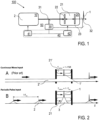
- Figure 1 shows an overview of a laser source apparatus 100 for generating solitons 1 with the input source device 10 and the optical resonator device 20 including an optical micro-resonator 21.
- the input source device 10 which is described with further details with reference to Figure 3 below, creates the input light field 2 comprising a pulse train (sequence) of laser pulses.
- the micro-resonator 21 has an incoupling resonator mirror 22 and an outcoupling resonator mirror 23, being adapted for incoupling the input light field 2 and outcoupling the solitons 1 (possibly with a portion of the transmitted input light field 2) for a subsequent application.
- a portion of the input light field 2 is directed via a beam splitter 31 to a sensor device 30 comprising e. g. a photo diode.
- the beam splitter 31 can be arranged for directing a portion of light reflected by the incoupling resonator mirror 22 of the resonator 21 and/or another beam splitter 32 can be arranged for directing a portion of light transmitted through the resonator 21 to the sensor device 30.
- a control unit 40 is provided including an input control device 41 and/or a resonator control device 42.
- the components can be provided separately or combined in the common unit 40 as shown with dashed line.
- the input source device 10 is controllable with the input control device 41.
- the input control device 41 is configured in dependency on the type of input source device 10 and input pulse parameters to be controlled. As an example, in a mode-locked laser the repetition rate can be controlled via changing the cavity length.
- the carrier envelope offset frequency can be controlled via the current of a pump diode of an optically pumped pulsed laser.
- the resonator control device 42 is provided for acting on the resonator in order to adapt resonance frequencies, in particular the FSR and/or an offset tuning, to the repetition rate and/or the carrier envelope offset frequency of the input pulse train.
- the resonator control device 42 includes e. g. a temperature control, a mechanical actor or an electro-optic tuning element.
- the sensor device 30 can be coupled with the control unit 40 for providing a control loop 50 for feedback controlling the input source device 10 and/or the resonator device 20, in particular the pulse repetition rate and the carrier envelope offset frequency and/or the resonance frequencies in dependency on the sensed parameters of the input laser field 2 and/or the solitons 1.
- Figure 2 shows a comparison of the known cw input based DKS generation ( Figure 2A , prior art) and the inventive pulse input based DKS generation ( Figure 2B ) along a spatial coordinate z.
- Figure 2A shows a cw driven micro-resonator 21'.
- a temporal dissipative soliton 1' can form inside the micro-resonator 21' and propagate with a roundtrip defined by the resonator's inverse free-spectral range (FSR) while being supported by the resonantly enhanced cw background of the input light field 2'.
- FSR inverse free-spectral range
- Figure 2 illustrates how the invention deviates from the concept of a continuous wave driving beam conventionally used for micro-resonators.
- the resonantly enhanced pulsed driving of the micro-resonator 21 is used for nonlinear optics and in particular the generation of DKS.
- This does not only correspond to a novel scheme of resonant supercontinuum generation, but could also allow for unprecedentedly efficient micro-resonator based ultra-short soliton pulse and frequency comb generation.
- the periodic train of driving pulses 2 replaces the cw holding beam ( Figure 2A ), so that inside the resonator cavity a resonantly enhanced pulse 3 co-propagates with the soliton pulse ( Figure 2B ).
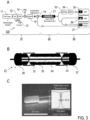
- FIG 3 shows further details of a practical example of a laser source device 100 according to the invention.
- the optical setup ( Figure 3A ) comprises the input source device 10, the resonator device 20 and a sensor device 30 (shown here for diagnostic purposes).
- the input source device 10 is provided by a pico-second periodic laser pulse generator (here: based on electro-optic intensity and phase modulators (IM/PM) 12.
- IM/PM electro-optic intensity and phase modulators
- a 1559 nm cw fiber laser 11 is strongly chirped using the EOM phase modulator 12 (driven by a tunable 9.77 GHz microwave source 13) and compressed into picosecond pulses via linear propagation in a chirped fiber-Bragg grating 14 for chirp compensation.
- the pulse repetition rate corresponds to the modulation frequency.
- a chirped fiber-Bragg grating 14 with a group delay dispersion (GDD) of 10 ps/nm is used for pulse compression.
- GDD group delay dispersion
- an intensity modulator Prior to phase modulation, an intensity modulator (IM) is used to carve out the modulation half period with the correct sign of chirp.
- IM intensity modulator
- Such EOM based pulse generator 12 allows for straightforward control of both, pulse repetition rate and pulse center wavelength (i.e. carrier envelope offset frequency).
- the pulses After chirp compensation in the CFBG 14, the pulses have a pulse duration of 2.4 ps and are characterized by an almost flat-top spectrum.
- the pulses are amplified in an erbium-doped fiber amplifier 15 up to 1.5 W of average power.
- the amplified pulses Prior to being coupled to the resonator device 20, the amplified pulses propagate through approximately 10 m of optical fiber resulting in moderate pulse shortening to 2.1 ps and formation of weak side pulses (peak power 13% of main pulse, separation from main pulse about 2 ps). This manifests itself in the generation of additional spectral lines.
- the threshold power reduction when compared to cw driving is in the same order.
- the resonator device 20 includes an optical fiber-based Fabry-Perot microresonator 21 as shown in Figure 3B and further illustrated with a photographic image in Figure 3C (see also [9]).
- the inset of Figure 3C shows the measured reflection and transmission of the resonator 21 when scanning across the resonance frequency with a cw laser.
- the microresonator 21 consist of a mm-scale length optical fiber 24 with a total lengths of about 10 mm whose end facets have been coated with highly reflecting, zero group delay dielectric Bragg-mirror coatings providing incoupling and outcoupling mirrors 22, 23.
- the resonator 21 has a FSR of 9.77 GHz, resonance width of 7 MHz and a linear coupling efficiency of 60%.
- This resonator design allows for a high-Q microresonator with a FSR low enough to be matched by the available driving laser source.
- the resonator fiber 24 is mounted inside a fiber optic ferrule 25 whose diameter matches the one of standard FC/PC fiber connectors.
- the present system is inherently fiber coupled using an input fiber coupler 26 and an output fiber coupler 27 ( Figure 3B ).
- the sensor device 30 is coupled with the output fiber coupler 27 of the laser source apparatus 100.
- the sensor device 30 includes an erbium doped fiber amplifier 33 (EDFA) and a bandpass filter 34 (BPF) coupled with an electronic spectrum analyzer 35, an optical spectrum analyzer 36 and an oscilloscope 37.
- EDFA erbium doped fiber amplifier
- BPF bandpass filter 34
- the transmitted spectrum of the resonator 21 measured with the sensor device 30 gives direct access to the intra-cavity soliton 1 field and is equivalent to a drop port that efficiently suppresses uncoupled input light 2 during soliton operation.
- the illustrated components of the sensor device 30 only serve a complete characterization of the generated DKS.
- the sensor device 30 comprises simple components, like at least one photo diode, optionally coupled with an electronic spectrum analyzer (see e. g. Figure 1 ).
- test results are described, obtained with the laser source device 100 according to the invention.
- the test results refer to the practical indication of soliton formation via pulsed driving, the characterization of the solitons, and investigating the of DKS generation.
- soliton formation is obtained by precisely matching first the central wavelength of the input source device 10 (wavelength defined by the cw fiber laser 11, see Figure 3 ) to a resonance of the resonator 21 and second the pulse repetition rate (defined by the modulation frequency) to the resonator's FSR.
- the pulse duration is 2.1 ps and the maximally coupled driving power approximately 100 mW.
- the regime of soliton formation is identified by repeatedly scanning the cw fiber lasers 11 wavelength across a resonance (from blue to red detuning) while at the same time slowly decreasing the microwave modulation frequency of the microwave source 13 around the value of the FSR of 9.77 GHz.
- the soliton formation is found, when the resonator transmission, that is the cumulative resonance shape of all driven modes, shows characteristic step features that are in marked similarity to the ones observed in known cw driven systems where they are directly related to formation of DKS [1].
- the observed transmission is essentially free of the random fluctuation of step length and height in the transmission spectrum. Strikingly, the step feature appears for a rather wide, 100 kHz spanning interval of driving pulse repetition rates, suggesting that DKS formation in a pulsed system is unexpectedly robust against a mismatch between FSR and pulse repetition rate.
- Figure 4 includes further tests results characterizing the solitons generated according to the invention.
- Figure 4A shows an optical spectrum of a single soliton obtained when driving with 2.1 ps pulses and a coupled power of maximally 100 mW. With a sech2-fit, a soliton pulse duration of 137 fs is found (see insert). The input pulse spectrum is indicated in the center, the additional spectra at shorter wavelength indicate the transmission spectra of bandpass filters (see e. g. BPF 34 in Figure 3A ) used for intermode beatnote detection.
- Figure 4A shows intermode beatnotes recorded using BPFs in the setup shown in Figure 3A (left/middle) and the adiabatic change of the soliton mode spacing by varying the external pulse repetition rate f rep within an interval of 60 kHz (upper curve is the max-hold trace of the beatnote signal) without losing the soliton state (right).
- Figure 4C shows a comparison of single and multiple (two) solitons transmission curves, and Figure 4AD shows the optical spectrum of two solitons obtained when driving with 2.4 ps pulses.
- Figure 4A shows the optical spectrum of DKS obtained after tuning the driving modes into the step-feature.
- This spectrum corresponds to single soliton pulse of 137 fs duration circulating stably in the resonator 21 with a pulse repetition rate of 9.77 GHz.
- this frequency comb spectrum (line spacing 9.77 GHz) consists of more than 1000 individual spectral lines (within 25 dB) and its envelope follows closely the characteristic sech2 shape.
- a particular advantage and distinct when compared to known cw driven systems is that there is no strong individual spectral component being orders of magnitude stronger than the soliton spectrum.
- the second spectral feature are the spectral 'ears' adjacent to the central portion of the driving laser spectrum.
- the inventive DKS generation driven by pulses without a cw holding beam is a surprising result found by the inventors, when the soliton co-propagates in sync with the driving laser input pulses 2 inside the resonator 1.
- the microwave beatnote generated by the repetitive, out-coupled soliton pulses is recorded and compared to the 9.77 GHz microwave signal that is used to drive the EOMs 12 of the input source device 10 (defining the driving pulse repetition rate).
- the beatnote detection is limited, via an optical bandpass filter, to spectral component of the soliton that do not overlap with the spectral content of the driving pulse ( Figure 4A ).
- the soliton spectrum Prior to filtering, the soliton spectrum is amplified via a low power EDFA 33 ( Figure 3A ) in order to reach a higher signal to noise ratio.
- the resulting beatnotes are shown in Figure 4B (left, middle). These beatnotes precisely correspond to the repetition rate of the driving laser, are perfectly stable and show 1 Hz resolution bandwidth limited signals, without any sidebands or sign of noise anywhere from DC to the carrier frequency. This, demonstrates the tight locking characteristics of the soliton to the driving pulse.
- one single soliton is created per input as observed with the single step features in the transmission.
- This is enables deterministic and reliable generation of single DKS states, which is challenging to achieve in conventional cw driven systems, yet highly desirable as the resulting optical spectrum is characterized by a smooth, unmodulated sech2 envelope ( Figure 4A ).
- the input pump pulses 2 can be arranged to also deterministically result in multi-soliton states evidenced by higher ⁇ step' height ( Figure 4C ).
- the corresponding optical spectra are characterized by a modulated envelope as shown in Figure 4D , where the spectral modulation corresponds to the inverse separation of the soliton pulses in time.
- the transmission for a laser scan generating multiple solitons is shown in Figure 4D . Similar to the single soliton case the resulting cumulative resonance shape does not show qualitative fluctuations between consecutive scans.
- identical soliton multi-soliton states can be reproduced by using identical driving pulse parameters (i. e. the exact optical spectrum is reproduced when the soliton is destroyed and regenerated with the same driving parameters).
- the stability of the spectral envelope of multi-soliton states over long time scales (> 30 mins) also agrees well with the solitons being not only loosely attached to but indeed tightly locked to a specific relative temporal position of the driving pulse.
- the ultra-low power soliton generation of the invention can be demonstrated by comparing the efficiency of a resonator device driven by optical input pulses when compared to continuous wave driven resonators.
- a resonator with a resonance width of 2.5 MHz and 9.80 GHz FSR is used.
- the coupling of the resonator is strongly under-coupled and reaches only 0.5%.
- Further optimization of the sample fabrication process can however yield critically coupled resonators with comparable linewidth.
- Single soliton generation is possible already when driving the resonator with 2.1 ps pulses and 3 mW of maximally coupled average power corresponding to pulse energies of approximately 300 fJ.
- the required average power is below the parametric threshold power in cw driving and even below the (thermal and nonlinear) bistability threshold.
- the pulsed driving allows to directly enter the single soliton state, without transiting through an intermediate state of breather solitons (no noise present in the transmission trace).
- This test result is confirmed by numerical simulations by the inventors. Further numerical simulations confirm that the required power for equivalent single soliton generation scales approximately with the number of in-phase driving modes (i.e. with the duty cycle of the driving pulse train). Generally, high average driving power and shorter driving pulse duration, but also lower anomalous GVD results in broader spectra.
- the inventors have found for the first time that a nonlinear optical resonator being driven by periodic optical pico-second pulses, whose corresponding optical modes are matched to the modes of the resonator, allow the formation of femtosecond DKS 'on-top' of the resonantly enhanced external driving input pulses.
- DKS formation does not require the external pulse repetition rate to exactly match the FSR of the resonator (or the corresponding natural soliton pulse repetition rate). Instead, the repetition rate of the external laser can even be tuned around this value without destroying the generated soliton circulating inside the resonator.
- the tests by the inventors reveal that indeed, the soliton stays tightly locked to the driving pump pulses and even adapts adiabatically to the externally imposed pulse repetition rate.
- This remarkable behavior is in agreement with numerical simulations that reveal the underlying plasticity of the soliton that via shifts and deformation of its spectral envelope can adapt to the externally imposed pulse repetition rate.
- the inventions demonstrates that pulsed pumping can significantly lower the average threshold power of DKS formation to below the parametric threshold power (and even the bistability power) of cw driven systems.
- An advantageous side effect of the highly efficient and 'targeted' pulse pumping is that, in contrast to conventional cw driven systems, the laser can be manually (i.e. slowly) tuned into the soliton state, without the need for rapid and complex actuation on the driving laser or the resonator.
Landscapes
- Physics & Mathematics (AREA)
- Electromagnetism (AREA)
- Optics & Photonics (AREA)
- Nonlinear Science (AREA)
- Engineering & Computer Science (AREA)
- Plasma & Fusion (AREA)
- General Physics & Mathematics (AREA)
- Lasers (AREA)
Claims (17)
- Laserquellenvorrichtung (100), die zum Erzeugen von zeitlich dissipativen Resonator-Solitonen (1) ausgebildet ist, umfassend:- eine Eingangsquelleneinrichtung (10), die ausgebildet ist, ein Eingangslichtfeld (2) als eine periodische Pulsfolge von Laserpulsen (3), die zeitlich durch ein endliches Intervall voneinander getrennt sind, bereitzustellen, und- eine optische Resonatoreinrichtung (20), die einen optischen Mikroresonator (21) mit einer optischen Weglänge kleiner oder gleich 1 cm und mit einer optischen Kerr-Nichtlinearität dritter Ordnung umfasst und mit der Eingangsquelleneinrichtung (10) gekoppelt ist, um die Resonator-Solitonen (1) durch das treibende Eingangslichtfeld (2) zu erzeugen,dadurch gekennzeichnet, dass- die Eingangsquelleneinrichtung (10) eine amplitudenmodulierte CW-Laserquelle oder eine phasenmodulierte CW-Laserquelle umfasst,- die Eingangsquelleneinrichtung (10) in einer Pulswiederholrate und einer Träger-Einhüllenden-Offset-Frequenz derart steuerbar ist, dass die optischen Moden der Laserpulse an Resonanzmoden des Resonators (21) angepasst sind,- eine Eingangssteuereinrichtung (41) zur Steuerung der Pulswiederholrate und der Träger-Einhüllenden-Offset-Frequenz der Eingangsquelleneinrichtung (10) vorgesehen ist, und- eine Sensoreinrichtung (30) zur Erfassung von Parametern der Resonator-Solitonen (1) und zur Überwachung eines Zustands einer Solitonenerzeugung angeordnet ist.
- Laserquellenvorrichtung nach Anspruch 1, wobei- die Eingangsquelleneinrichtung (10) ausgebildet ist, die Pulsfolge mit einem Tastverhältnis von Pulsdauer geteilt durch Pulswiederholperiode unter 1/2, insbesondere unter 1/10, bereitzustellen.
- Laserquellenvorrichtung nach einem der vorangehenden Ansprüche, wobei- die Eingangsquelleneinrichtung (10) in der Pulsdauer so steuerbar ist, dass pro Eingangslaserpuls (3) mindestens ein einzelnes Resonator-Soliton (1) erzeugt wird.
- Laserquellenvorrichtung nach einem der vorangehenden Ansprüche, wobei- die Sensoreinrichtung (30) ferner zur Erfassung von Parametern des Eingangslichtfeldes (2) angeordnet ist.
- Laserquellenvorrichtung nach einem der vorangehenden Ansprüche, wobei- der Mikroresonator (21) in Resonanzfrequenzen derart steuerbar ist, dass die optischen Moden der Laserpulse an die Resonanzmoden des Mikroresonators (21) angepasst sind.
- Laserquellenvorrichtung nach Anspruch 5, wobei- die Eingangsquelleneinrichtung (10) und/oder der Mikroresonator (21) in der Pulswiederholrate derart steuerbar ist, dass die Pulswiederholrate ein ganzzahliger Bruchteil oder ein ganzzahliges Vielfaches des freien Spektralbereichs des Mikroresonators (21) ist.
- Laserquellenvorrichtung nach einem der vorangehenden Ansprüche, ferner umfassend- eine Resonatorsteuereinrichtung (42), die ausgebildet ist, auf den Mikroresonator (21) einzuwirken, um die Resonanzfrequenzen des Mikroresonators (21) an die Pulswiederholrate und/oder die Träger-Einhüllenden-Offset-Frequenz der Eingangsquelleneinrichtung (10) anzupassen.
- Laserquellenvorrichtung nach Anspruch 7, ferner enthaltend- einen Regelkreis (50), der die Sensoreinrichtung (30) und mindestens eine von der Eingangssteuereinrichtung (41) und der Resonatorsteuereinrichtung (42) enthält, wobei- die Eingangssteuereinrichtung (41) und/oder die Resonatorsteuereinrichtung (42) ausgebildet sind, in Abhängigkeit von den erfassten Parametern auf die Eingangsquelleneinrichtung (10) und/oder den Mikroresonator (21) einwirken.
- Laserquellenvorrichtung nach einem der vorangehenden Ansprüche, wobei die Eingangsquelleneinrichtung (10) mindestens eines der Merkmale aufweist:- die Eingangsquelleneinrichtung (10) ist ausgebildet, die Pulsfolge von Laserpulsen mit einer Dauer von 10 fs bis 100 ps zu liefern,- die Eingangsquelleneinrichtung (10) ist ausgebildet, die Pulsfolge von Laserpulsen mit einer Wiederholrate von 10 MHz bis 100 GHz zu liefern, und- die Eingangsquelleneinrichtung (10) ist ausgebildet, die Laserpulse mit einem Frequenzchirp zu versehen.
- Laserquellenvorrichtung nach einem der vorangehenden Ansprüche, wobei der Mikroresonator (21) mindestens eines der Merkmale aufweist:- der Mikroresonator (21) umfasst einen Fabry-Perot-Resonator,- der Mikroresonator (21) umfasst eine in einer Ferrule enthaltende, beschichtete optische Faser,- der Mikroresonator (21) umfasst einen Wellenleiter,- der Mikroresonator (21) ist aus SiN, AlN, GaN, SiO2 oder Chalkogenidglas hergestellt, und- der Mikroresonator ist aus kristallinem optischen Material, insbesondere aus CaF2, MgF2, BaF2, Diamant, LiNbO3, KNbO3, Silizium, Galliumarsenid oder Indiumphosphid, hergestellt.
- Laserquellenvorrichtung nach einem der vorhergehenden Ansprüche, wobei- eine serielle Kaskadenanordnung von mehreren Laserquellenvorrichtungen vorgesehen ist, wobei eine der Laserquellenvorrichtungen als Eingangsquelleneinrichtung einer nachfolgenden Laserquellenvorrichtung der Laserquellenvorrichtungen angeordnet ist.
- Verfahren zur Erzeugung von zeitlich dissipativen Resonator-Solitonen (1), umfassend die Schritte:- Bereitstellen eines Eingangslichtfeldes (2) als eine periodische Pulsfolge von Laserpulsen (3), die zeitlich durch ein endliches Intervall voneinander getrennt sind, wobei das Eingangslichtfeld (2) mit einer Eingangsquelleneinrichtung (10) bereitgestellt wird, und- Erzeugen der Resonator-Solitonen (1) durch das treibende Eingangslichtfeld (2) mit einer Resonatoreinrichtung (20), die einen optischen Mikroresonator (21) mit einer optischen Weglänge kleiner oder gleich 1 cm und mit einer optischen Kerr-Nichtlinearität dritter Ordnung umfasst und mit der Eingangsquelleneinrichtung (10) gekoppelt ist,dadurch gekennzeichnet, dass- die Eingangsquelleneinrichtung (10) eine amplitudenmodulierte CW-Laserquelle oder eine phasenmodulierte CW-Laserquelle umfasst, und- das Verfahren einen weiteren Schritt eines Erfassens von Parametern der Resonator-Solitonen (1) umfasst, wobei- die Pulswiederholrate zunächst an den freien Spektralbereich des Resonators, einen ganzzahligen Bruchteil des freien Spektralbereichs oder ein ganzzahliges Vielfaches des freien Spektralbereichs angepasst wird,- die Träger-Einhüllenden-Offset-Frequenz der Pulsfolge anschließend so gescannt wird, dass die optischen Moden der Pulsfolge über Resonanzfrequenzen des Mikroresonators (21) scannen, und- das Scannen der Träger-Einhüllenden-Offset-Frequenz der Pulsfolge gestoppt wird, sobald der Solitonzustand erreicht ist.
- Verfahren nach Anspruch 12, wobei- die Eingangsquelleneinrichtung (10) die Pulsfolge mit einem Tastverhältnis von Pulsdauer geteilt durch Pulswiederholperiode unter 1/2, insbesondere unter 1/10, bereitstellt.
- Verfahren nach Anspruch 13, enthaltend den Schritt:- Steuern der Pulsdauer der Eingangslaserpulse (3) derart, dass pro Eingangslaserpuls (3) mindestens ein einzelnes Resonator-Soliton (1) erzeugt wird.
- Verfahren nach einem der Ansprüche 12 bis 14, enthaltend den Schritt:- Erfassen von Parametern des Eingangslichtfeldes (2).
- Verfahren nach einem der Ansprüche 12 bis 15, ferner enthaltend:- Steuern der Resonanzfrequenzen des Resonators (21) in Abhängigkeit von den erfassten Parametern.
- Verfahren nach einem der Ansprüche 12 bis 16, wobei- eine serielle Kaskadenanordnung von mehreren Laserquellenvorrichtungen vorgesehen ist, wobei eine der Laserquellenvorrichtungen als Eingangsquelleneinrichtung einer nachfolgenden Laserquellenvorrichtung der Laserquellenvorrichtungen angeordnet ist.
Applications Claiming Priority (1)
| Application Number | Priority Date | Filing Date | Title |
|---|---|---|---|
| PCT/EP2016/002135 WO2018113893A1 (en) | 2016-12-19 | 2016-12-19 | Laser source apparatus and method for generating temporal dissipative cavity solitons |
Publications (2)
| Publication Number | Publication Date |
|---|---|
| EP3555702A1 EP3555702A1 (de) | 2019-10-23 |
| EP3555702B1 true EP3555702B1 (de) | 2023-04-19 |
Family
ID=57629552
Family Applications (1)
| Application Number | Title | Priority Date | Filing Date |
|---|---|---|---|
| EP16819265.6A Active EP3555702B1 (de) | 2016-12-19 | 2016-12-19 | Laserquelle und verfahren zur erzeugung von temporären dissipativen hohlraumsolitonen |
Country Status (3)
| Country | Link |
|---|---|
| US (1) | US11048144B2 (de) |
| EP (1) | EP3555702B1 (de) |
| WO (1) | WO2018113893A1 (de) |
Families Citing this family (6)
| Publication number | Priority date | Publication date | Assignee | Title |
|---|---|---|---|---|
| US11092424B2 (en) * | 2017-08-02 | 2021-08-17 | The Trustees Of Columbia University In The City Of New York | Microresonator-frequency-comb-based platform for clinical high-resolution optical coherence tomography |
| US11050214B2 (en) * | 2018-05-02 | 2021-06-29 | Massachusetts Institute Of Technology | Narrow-linewidth microcavity brillouin laser with suppressed temperature fluctuations |
| CN109494559B (zh) * | 2018-12-27 | 2020-12-04 | 上海交通大学 | 孤子光频梳产生装置及操作方法 |
| WO2021194630A2 (en) * | 2020-01-31 | 2021-09-30 | The General Hospital Corporation | Frequency-comb generation based on electro-optic phase-code mode-locking for circular-ranging oct |
| SE545304C2 (en) | 2021-07-08 | 2023-06-27 | Oskar Bjarki Helgason | An optical resonator frequency comb |
| CN114006659B (zh) * | 2021-10-29 | 2023-06-06 | 中国地质大学(武汉) | 基于无源谐振腔的高阶矢量孤子产生系统及方法 |
Family Cites Families (2)
| Publication number | Priority date | Publication date | Assignee | Title |
|---|---|---|---|---|
| US9348194B2 (en) | 2013-02-28 | 2016-05-24 | Ecole Polytechnique Federale De Lausanne (Epfl) | Generating optical pulses via a soliton state of an optical microresonator |
| CN109478754A (zh) | 2016-06-29 | 2019-03-15 | 瑞士Csem电子显微技术研发中心 | 光学谐振器、光学谐振器的制造方法及其应用 |
-
2016
- 2016-12-19 EP EP16819265.6A patent/EP3555702B1/de active Active
- 2016-12-19 WO PCT/EP2016/002135 patent/WO2018113893A1/en not_active Ceased
- 2016-12-19 US US16/471,309 patent/US11048144B2/en active Active
Non-Patent Citations (1)
| Title |
|---|
| JAE K JANG ET AL: "Writing and erasing of temporal cavity solitons by direct phase modulation of the cavity driving field", ARXIV.ORG, CORNELL UNIVERSITY LIBRARY, 201 OLIN LIBRARY CORNELL UNIVERSITY ITHACA, NY 14853, 21 January 2015 (2015-01-21), XP081329329, DOI: 10.1364/OL.40.004755 * |
Also Published As
| Publication number | Publication date |
|---|---|
| EP3555702A1 (de) | 2019-10-23 |
| US11048144B2 (en) | 2021-06-29 |
| WO2018113893A1 (en) | 2018-06-28 |
| US20190317379A1 (en) | 2019-10-17 |
Similar Documents
| Publication | Publication Date | Title |
|---|---|---|
| EP3555702B1 (de) | Laserquelle und verfahren zur erzeugung von temporären dissipativen hohlraumsolitonen | |
| EP4189478B1 (de) | Aktiver optischer resonator zur frequenzumwandlung | |
| Anderson et al. | Coexistence of multiple nonlinear states in a tristable passive Kerr resonator | |
| US7982944B2 (en) | Method and apparatus for optical frequency comb generation using a monolithic micro-resonator | |
| EP1988425B1 (de) | Verfahren und Vorrichtung zur Erzeugung eines optischen Frequenzkamms mittels eines monolithischen Mikroresonators | |
| Jang et al. | Observation of Arnold tongues in coupled soliton Kerr frequency combs | |
| CN110168444A (zh) | 绝热色散管理的频率梳产生 | |
| WO2016048740A2 (en) | Low carrier phase noise fiber oscillators | |
| CN113875102A (zh) | 驱动腔飞秒源 | |
| Schimpf et al. | Frequency-comb-based laser system producing stable optical beat pulses with picosecond durations suitable for high-precision multi-cycle terahertz-wave generation and rapid detection | |
| Bao et al. | Oscillatory motion of a counterpropagating Kerr soliton dimer | |
| Yang et al. | Actively mode-locked fiber optical parametric oscillator | |
| Xiao et al. | Modeling the Kerr comb of a pulse pumped FP microresonator with normal dispersion | |
| US20250260208A1 (en) | Mode-locking method and system | |
| Yang et al. | Fiber optical parametric oscillator based on highly nonlinear dispersion-shifted fiber | |
| Zhou et al. | A time-dispersion-tuned picosecond fiber-optical parametric oscillator | |
| Yang et al. | Dispersion-tuned harmonically mode-locked fiber-optical parametric oscillator | |
| JPH04357892A (ja) | モード同期光ファイバレーザ装置 | |
| Salik et al. | EDFA-based coupled opto-electronic oscillator and its phase noise | |
| Bolotov et al. | Seeded Intermodal Four-Wave Mixing in a Few Moded Fiber | |
| Wang | On-chip microresonator frequency combs: Generation dynamics, power transfer, and time-domain characterization | |
| Bojęś et al. | Precise passive synchronization of dissipative soliton resonance lasers via cascaded cross-phase-and cross-absorption-modulation for mid-infrared mode-locked pulse generation | |
| Trask | Opto-Electronic Oscillator driven Electro-Optic Modulator based Optical Frequency Comb | |
| Honig et al. | Diode-pumped 22-W average-power uv laser with user-selectable pulse width and> 50% conversion efficiency | |
| Boggio et al. | Optical Frequency Comb Generated with an Amplitude Modulated Pump in Silicon Nitride Ring-resonators. |
Legal Events
| Date | Code | Title | Description |
|---|---|---|---|
| STAA | Information on the status of an ep patent application or granted ep patent |
Free format text: STATUS: UNKNOWN |
|
| STAA | Information on the status of an ep patent application or granted ep patent |
Free format text: STATUS: THE INTERNATIONAL PUBLICATION HAS BEEN MADE |
|
| PUAI | Public reference made under article 153(3) epc to a published international application that has entered the european phase |
Free format text: ORIGINAL CODE: 0009012 |
|
| STAA | Information on the status of an ep patent application or granted ep patent |
Free format text: STATUS: REQUEST FOR EXAMINATION WAS MADE |
|
| 17P | Request for examination filed |
Effective date: 20190717 |
|
| AK | Designated contracting states |
Kind code of ref document: A1 Designated state(s): AL AT BE BG CH CY CZ DE DK EE ES FI FR GB GR HR HU IE IS IT LI LT LU LV MC MK MT NL NO PL PT RO RS SE SI SK SM TR |
|
| AX | Request for extension of the european patent |
Extension state: BA ME |
|
| DAV | Request for validation of the european patent (deleted) | ||
| DAX | Request for extension of the european patent (deleted) | ||
| STAA | Information on the status of an ep patent application or granted ep patent |
Free format text: STATUS: EXAMINATION IS IN PROGRESS |
|
| 17Q | First examination report despatched |
Effective date: 20200619 |
|
| GRAP | Despatch of communication of intention to grant a patent |
Free format text: ORIGINAL CODE: EPIDOSNIGR1 |
|
| STAA | Information on the status of an ep patent application or granted ep patent |
Free format text: STATUS: GRANT OF PATENT IS INTENDED |
|
| INTG | Intention to grant announced |
Effective date: 20221109 |
|
| GRAS | Grant fee paid |
Free format text: ORIGINAL CODE: EPIDOSNIGR3 |
|
| GRAA | (expected) grant |
Free format text: ORIGINAL CODE: 0009210 |
|
| STAA | Information on the status of an ep patent application or granted ep patent |
Free format text: STATUS: THE PATENT HAS BEEN GRANTED |
|
| AK | Designated contracting states |
Kind code of ref document: B1 Designated state(s): AL AT BE BG CH CY CZ DE DK EE ES FI FR GB GR HR HU IE IS IT LI LT LU LV MC MK MT NL NO PL PT RO RS SE SI SK SM TR |
|
| REG | Reference to a national code |
Ref country code: GB Ref legal event code: FG4D |
|
| REG | Reference to a national code |
Ref country code: DE Ref legal event code: R096 Ref document number: 602016078921 Country of ref document: DE |
|
| REG | Reference to a national code |
Ref country code: CH Ref legal event code: EP |
|
| REG | Reference to a national code |
Ref country code: IE Ref legal event code: FG4D |
|
| REG | Reference to a national code |
Ref country code: AT Ref legal event code: REF Ref document number: 1561640 Country of ref document: AT Kind code of ref document: T Effective date: 20230515 |
|
| REG | Reference to a national code |
Ref country code: LT Ref legal event code: MG9D |
|
| REG | Reference to a national code |
Ref country code: NL Ref legal event code: MP Effective date: 20230419 |
|
| REG | Reference to a national code |
Ref country code: AT Ref legal event code: MK05 Ref document number: 1561640 Country of ref document: AT Kind code of ref document: T Effective date: 20230419 |
|
| PG25 | Lapsed in a contracting state [announced via postgrant information from national office to epo] |
Ref country code: NL Free format text: LAPSE BECAUSE OF FAILURE TO SUBMIT A TRANSLATION OF THE DESCRIPTION OR TO PAY THE FEE WITHIN THE PRESCRIBED TIME-LIMIT Effective date: 20230419 |
|
| PG25 | Lapsed in a contracting state [announced via postgrant information from national office to epo] |
Ref country code: SE Free format text: LAPSE BECAUSE OF FAILURE TO SUBMIT A TRANSLATION OF THE DESCRIPTION OR TO PAY THE FEE WITHIN THE PRESCRIBED TIME-LIMIT Effective date: 20230419 Ref country code: PT Free format text: LAPSE BECAUSE OF FAILURE TO SUBMIT A TRANSLATION OF THE DESCRIPTION OR TO PAY THE FEE WITHIN THE PRESCRIBED TIME-LIMIT Effective date: 20230821 Ref country code: NO Free format text: LAPSE BECAUSE OF FAILURE TO SUBMIT A TRANSLATION OF THE DESCRIPTION OR TO PAY THE FEE WITHIN THE PRESCRIBED TIME-LIMIT Effective date: 20230719 Ref country code: ES Free format text: LAPSE BECAUSE OF FAILURE TO SUBMIT A TRANSLATION OF THE DESCRIPTION OR TO PAY THE FEE WITHIN THE PRESCRIBED TIME-LIMIT Effective date: 20230419 Ref country code: AT Free format text: LAPSE BECAUSE OF FAILURE TO SUBMIT A TRANSLATION OF THE DESCRIPTION OR TO PAY THE FEE WITHIN THE PRESCRIBED TIME-LIMIT Effective date: 20230419 |
|
| PG25 | Lapsed in a contracting state [announced via postgrant information from national office to epo] |
Ref country code: RS Free format text: LAPSE BECAUSE OF FAILURE TO SUBMIT A TRANSLATION OF THE DESCRIPTION OR TO PAY THE FEE WITHIN THE PRESCRIBED TIME-LIMIT Effective date: 20230419 Ref country code: PL Free format text: LAPSE BECAUSE OF FAILURE TO SUBMIT A TRANSLATION OF THE DESCRIPTION OR TO PAY THE FEE WITHIN THE PRESCRIBED TIME-LIMIT Effective date: 20230419 Ref country code: LV Free format text: LAPSE BECAUSE OF FAILURE TO SUBMIT A TRANSLATION OF THE DESCRIPTION OR TO PAY THE FEE WITHIN THE PRESCRIBED TIME-LIMIT Effective date: 20230419 Ref country code: LT Free format text: LAPSE BECAUSE OF FAILURE TO SUBMIT A TRANSLATION OF THE DESCRIPTION OR TO PAY THE FEE WITHIN THE PRESCRIBED TIME-LIMIT Effective date: 20230419 Ref country code: IS Free format text: LAPSE BECAUSE OF FAILURE TO SUBMIT A TRANSLATION OF THE DESCRIPTION OR TO PAY THE FEE WITHIN THE PRESCRIBED TIME-LIMIT Effective date: 20230819 Ref country code: HR Free format text: LAPSE BECAUSE OF FAILURE TO SUBMIT A TRANSLATION OF THE DESCRIPTION OR TO PAY THE FEE WITHIN THE PRESCRIBED TIME-LIMIT Effective date: 20230419 Ref country code: GR Free format text: LAPSE BECAUSE OF FAILURE TO SUBMIT A TRANSLATION OF THE DESCRIPTION OR TO PAY THE FEE WITHIN THE PRESCRIBED TIME-LIMIT Effective date: 20230720 Ref country code: AL Free format text: LAPSE BECAUSE OF FAILURE TO SUBMIT A TRANSLATION OF THE DESCRIPTION OR TO PAY THE FEE WITHIN THE PRESCRIBED TIME-LIMIT Effective date: 20230419 |
|
| PG25 | Lapsed in a contracting state [announced via postgrant information from national office to epo] |
Ref country code: FI Free format text: LAPSE BECAUSE OF FAILURE TO SUBMIT A TRANSLATION OF THE DESCRIPTION OR TO PAY THE FEE WITHIN THE PRESCRIBED TIME-LIMIT Effective date: 20230419 |
|
| PG25 | Lapsed in a contracting state [announced via postgrant information from national office to epo] |
Ref country code: SK Free format text: LAPSE BECAUSE OF FAILURE TO SUBMIT A TRANSLATION OF THE DESCRIPTION OR TO PAY THE FEE WITHIN THE PRESCRIBED TIME-LIMIT Effective date: 20230419 |
|
| REG | Reference to a national code |
Ref country code: DE Ref legal event code: R097 Ref document number: 602016078921 Country of ref document: DE |
|
| PG25 | Lapsed in a contracting state [announced via postgrant information from national office to epo] |
Ref country code: SM Free format text: LAPSE BECAUSE OF FAILURE TO SUBMIT A TRANSLATION OF THE DESCRIPTION OR TO PAY THE FEE WITHIN THE PRESCRIBED TIME-LIMIT Effective date: 20230419 Ref country code: SK Free format text: LAPSE BECAUSE OF FAILURE TO SUBMIT A TRANSLATION OF THE DESCRIPTION OR TO PAY THE FEE WITHIN THE PRESCRIBED TIME-LIMIT Effective date: 20230419 Ref country code: RO Free format text: LAPSE BECAUSE OF FAILURE TO SUBMIT A TRANSLATION OF THE DESCRIPTION OR TO PAY THE FEE WITHIN THE PRESCRIBED TIME-LIMIT Effective date: 20230419 Ref country code: EE Free format text: LAPSE BECAUSE OF FAILURE TO SUBMIT A TRANSLATION OF THE DESCRIPTION OR TO PAY THE FEE WITHIN THE PRESCRIBED TIME-LIMIT Effective date: 20230419 Ref country code: DK Free format text: LAPSE BECAUSE OF FAILURE TO SUBMIT A TRANSLATION OF THE DESCRIPTION OR TO PAY THE FEE WITHIN THE PRESCRIBED TIME-LIMIT Effective date: 20230419 Ref country code: CZ Free format text: LAPSE BECAUSE OF FAILURE TO SUBMIT A TRANSLATION OF THE DESCRIPTION OR TO PAY THE FEE WITHIN THE PRESCRIBED TIME-LIMIT Effective date: 20230419 |
|
| PLBE | No opposition filed within time limit |
Free format text: ORIGINAL CODE: 0009261 |
|
| STAA | Information on the status of an ep patent application or granted ep patent |
Free format text: STATUS: NO OPPOSITION FILED WITHIN TIME LIMIT |
|
| 26N | No opposition filed |
Effective date: 20240122 |
|
| PG25 | Lapsed in a contracting state [announced via postgrant information from national office to epo] |
Ref country code: SI Free format text: LAPSE BECAUSE OF FAILURE TO SUBMIT A TRANSLATION OF THE DESCRIPTION OR TO PAY THE FEE WITHIN THE PRESCRIBED TIME-LIMIT Effective date: 20230419 |
|
| PG25 | Lapsed in a contracting state [announced via postgrant information from national office to epo] |
Ref country code: SI Free format text: LAPSE BECAUSE OF FAILURE TO SUBMIT A TRANSLATION OF THE DESCRIPTION OR TO PAY THE FEE WITHIN THE PRESCRIBED TIME-LIMIT Effective date: 20230419 Ref country code: IT Free format text: LAPSE BECAUSE OF FAILURE TO SUBMIT A TRANSLATION OF THE DESCRIPTION OR TO PAY THE FEE WITHIN THE PRESCRIBED TIME-LIMIT Effective date: 20230419 |
|
| PG25 | Lapsed in a contracting state [announced via postgrant information from national office to epo] |
Ref country code: LU Free format text: LAPSE BECAUSE OF NON-PAYMENT OF DUE FEES Effective date: 20231219 |
|
| PG25 | Lapsed in a contracting state [announced via postgrant information from national office to epo] |
Ref country code: MC Free format text: LAPSE BECAUSE OF FAILURE TO SUBMIT A TRANSLATION OF THE DESCRIPTION OR TO PAY THE FEE WITHIN THE PRESCRIBED TIME-LIMIT Effective date: 20230419 |
|
| REG | Reference to a national code |
Ref country code: BE Ref legal event code: MM Effective date: 20231231 |
|
| PG25 | Lapsed in a contracting state [announced via postgrant information from national office to epo] |
Ref country code: MC Free format text: LAPSE BECAUSE OF FAILURE TO SUBMIT A TRANSLATION OF THE DESCRIPTION OR TO PAY THE FEE WITHIN THE PRESCRIBED TIME-LIMIT Effective date: 20230419 Ref country code: LU Free format text: LAPSE BECAUSE OF NON-PAYMENT OF DUE FEES Effective date: 20231219 |
|
| REG | Reference to a national code |
Ref country code: IE Ref legal event code: MM4A |
|
| PG25 | Lapsed in a contracting state [announced via postgrant information from national office to epo] |
Ref country code: IE Free format text: LAPSE BECAUSE OF NON-PAYMENT OF DUE FEES Effective date: 20231219 |
|
| PG25 | Lapsed in a contracting state [announced via postgrant information from national office to epo] |
Ref country code: BE Free format text: LAPSE BECAUSE OF NON-PAYMENT OF DUE FEES Effective date: 20231231 |
|
| PG25 | Lapsed in a contracting state [announced via postgrant information from national office to epo] |
Ref country code: IE Free format text: LAPSE BECAUSE OF NON-PAYMENT OF DUE FEES Effective date: 20231219 Ref country code: BE Free format text: LAPSE BECAUSE OF NON-PAYMENT OF DUE FEES Effective date: 20231231 |
|
| PG25 | Lapsed in a contracting state [announced via postgrant information from national office to epo] |
Ref country code: BG Free format text: LAPSE BECAUSE OF FAILURE TO SUBMIT A TRANSLATION OF THE DESCRIPTION OR TO PAY THE FEE WITHIN THE PRESCRIBED TIME-LIMIT Effective date: 20230419 |
|
| PG25 | Lapsed in a contracting state [announced via postgrant information from national office to epo] |
Ref country code: BG Free format text: LAPSE BECAUSE OF FAILURE TO SUBMIT A TRANSLATION OF THE DESCRIPTION OR TO PAY THE FEE WITHIN THE PRESCRIBED TIME-LIMIT Effective date: 20230419 |
|
| PGFP | Annual fee paid to national office [announced via postgrant information from national office to epo] |
Ref country code: DE Payment date: 20241216 Year of fee payment: 9 |
|
| PGFP | Annual fee paid to national office [announced via postgrant information from national office to epo] |
Ref country code: CH Payment date: 20250101 Year of fee payment: 9 |
|
| PG25 | Lapsed in a contracting state [announced via postgrant information from national office to epo] |
Ref country code: CY Free format text: LAPSE BECAUSE OF FAILURE TO SUBMIT A TRANSLATION OF THE DESCRIPTION OR TO PAY THE FEE WITHIN THE PRESCRIBED TIME-LIMIT; INVALID AB INITIO Effective date: 20161219 |
|
| PG25 | Lapsed in a contracting state [announced via postgrant information from national office to epo] |
Ref country code: HU Free format text: LAPSE BECAUSE OF FAILURE TO SUBMIT A TRANSLATION OF THE DESCRIPTION OR TO PAY THE FEE WITHIN THE PRESCRIBED TIME-LIMIT; INVALID AB INITIO Effective date: 20161219 |
|
| PG25 | Lapsed in a contracting state [announced via postgrant information from national office to epo] |
Ref country code: TR Free format text: LAPSE BECAUSE OF FAILURE TO SUBMIT A TRANSLATION OF THE DESCRIPTION OR TO PAY THE FEE WITHIN THE PRESCRIBED TIME-LIMIT Effective date: 20230419 |
|
| REG | Reference to a national code |
Ref country code: CH Ref legal event code: U11 Free format text: ST27 STATUS EVENT CODE: U-0-0-U10-U11 (AS PROVIDED BY THE NATIONAL OFFICE) Effective date: 20260101 |
|
| PGFP | Annual fee paid to national office [announced via postgrant information from national office to epo] |
Ref country code: GB Payment date: 20251230 Year of fee payment: 10 |
|
| PGFP | Annual fee paid to national office [announced via postgrant information from national office to epo] |
Ref country code: FR Payment date: 20251230 Year of fee payment: 10 |