EP3555565B1 - Navigationssensor mit dominanter achse - Google Patents
Navigationssensor mit dominanter achse Download PDFInfo
- Publication number
- EP3555565B1 EP3555565B1 EP17826400.8A EP17826400A EP3555565B1 EP 3555565 B1 EP3555565 B1 EP 3555565B1 EP 17826400 A EP17826400 A EP 17826400A EP 3555565 B1 EP3555565 B1 EP 3555565B1
- Authority
- EP
- European Patent Office
- Prior art keywords
- magnetic field
- sensor
- field sensor
- magneto
- sensing elements
- Prior art date
- Legal status (The legal status is an assumption and is not a legal conclusion. Google has not performed a legal analysis and makes no representation as to the accuracy of the status listed.)
- Not-in-force
Links
Images




Classifications
-
- A—HUMAN NECESSITIES
- A61—MEDICAL OR VETERINARY SCIENCE; HYGIENE
- A61B—DIAGNOSIS; SURGERY; IDENTIFICATION
- A61B5/00—Measuring for diagnostic purposes; Identification of persons
- A61B5/06—Devices, other than using radiation, for detecting or locating foreign bodies ; Determining position of diagnostic devices within or on the body of the patient
- A61B5/061—Determining position of a probe within the body employing means separate from the probe, e.g. sensing internal probe position employing impedance electrodes on the surface of the body
- A61B5/062—Determining position of a probe within the body employing means separate from the probe, e.g. sensing internal probe position employing impedance electrodes on the surface of the body using magnetic field
-
- G—PHYSICS
- G01—MEASURING; TESTING
- G01V—GEOPHYSICS; GRAVITATIONAL MEASUREMENTS; DETECTING MASSES OR OBJECTS; TAGS
- G01V3/00—Electric or magnetic prospecting or detecting; Measuring magnetic field characteristics of the earth, e.g. declination, deviation
- G01V3/08—Electric or magnetic prospecting or detecting; Measuring magnetic field characteristics of the earth, e.g. declination, deviation operating with magnetic or electric fields produced or modified by objects or geological structures or by detecting devices
-
- G—PHYSICS
- G01—MEASURING; TESTING
- G01R—MEASURING ELECTRIC VARIABLES; MEASURING MAGNETIC VARIABLES
- G01R33/00—Arrangements or instruments for measuring magnetic variables
- G01R33/0005—Geometrical arrangement of magnetic sensor elements; Apparatus combining different magnetic sensor types
-
- G—PHYSICS
- G01—MEASURING; TESTING
- G01R—MEASURING ELECTRIC VARIABLES; MEASURING MAGNETIC VARIABLES
- G01R33/00—Arrangements or instruments for measuring magnetic variables
- G01R33/0011—Arrangements or instruments for measuring magnetic variables comprising means, e.g. flux concentrators, flux guides, for guiding or concentrating the magnetic flux, e.g. to the magnetic sensor
-
- G—PHYSICS
- G01—MEASURING; TESTING
- G01R—MEASURING ELECTRIC VARIABLES; MEASURING MAGNETIC VARIABLES
- G01R33/00—Arrangements or instruments for measuring magnetic variables
- G01R33/02—Measuring direction or magnitude of magnetic fields or magnetic flux
- G01R33/06—Measuring direction or magnitude of magnetic fields or magnetic flux using galvano-magnetic devices
Definitions
- the present disclosure relates to systems, methods, and devices for tracking items. More specifically, the disclosure relates to systems, methods, and devices for electro-magnetically tracking medical devices used in medical procedures.
- Tracking systems can use externally generated magnetic fields that are sensed by at least one tracking sensor in the tracked medical device.
- the externally generated magnetic fields provide a fixed frame of reference, and the tracking sensor senses the magnetic fields to determine the location and orientation of the sensor in relation to the fixed frame of reference.
- Documents WO 2016/087970 A1 , US 6,484,118 B1 and WO 2016/196985 A1 relate to various medical devices including position sensors.
- a sensor assembly in accordance with the invention includes a first magnetic field sensor and a second magnetic field sensor.
- the first magnetic field sensor includes a first substrate and a first elongated magnetic field sensor component extending a first length.
- the second magnetic field sensor includes a second substrate and a second elongated magnetic field sensor component extending a second length that is shorter than the first length.
- the first magnetic field sensor has a greater sensitivity to a sensed magnetic field than the second magnetic field sensor.
- the first elongated magnetic field sensor component is first flux guide, and wherein the second elongated magnetic field sensor is a second flux guide.
- the first magnetic field sensor includes a first magneto-resistive (MR) sensing element positioned adjacent the first flux guide, and wherein the second magnetic field sensor includes a second MR sensing element positioned adjacent the second flux guide.
- MR magneto-resistive
- the first and second MR sensing elements are one of giant-magneto-resistive sensing elements, tunneling-magneto-resistive sensing elements, hall-effect sensing elements, colossal magneto-resistive sensing elements, extraordinary magneto-resistive sensing elements, and spin hall sensing elements.
- the first elongated magnetic field sensor component is a first anisotropic-magneto-resistive (AMR) sensing element, wherein the second elongated magnetic field sensor component is a second AMR sensing element.
- AMR anisotropic-magneto-resistive
- the first magnetic field sensor is configured to sense a first component of a magnetic field along a first axis
- the second magnetic field sensor is configured to sense a second component of the magnetic field along a second axis
- the first magnetic field sensor and the second magnetic field sensor are coupled to a common substrate.
- the sensor assembly further includes a third magnetic field sensor including a third substrate and a third elongated magnetic field sensor component extending a third length that is shorter than the first length.
- the first magnetic field sensor is at least twice as sensitive as the second magnetic field sensor.
- a system in an embodiment, includes the inventive sensor assembly and a magnetic field generator configured to generate a magnetic field and a probe having a longitudinal axis and with the sensor assembly positioned at or near a distal end of the probe.
- the first magnetic field sensor of the system is configured to sense a first component of the magnetic field along the longitudinal axis, while the second magnetic field sensor is configured to sense a second component of the magnetic field along a second axis, and wherein the first magnetic sensor has a greater sensitivity to the first component of the magnetic field than a sensitivity of the second magnetic field sensor with respect to the second component of the magnetic field.
- the first magnetic field sensor includes a first magneto-resistive (MR) sensing element
- the second magnetic field sensor includes a second MR sensing element, wherein the first MR sensing element is longer than the second MR sensing element
- the first flux guide may be longer than the second flux guide.
- the first magnetic field sensor includes a first magneto-resistive (MR) sensing element
- the second magnetic field sensor includes a second MR sensing element
- the first and second magnetic field sensors are one of giant-magneto-resistive sensing elements, tunneling-magneto-resistive sensing elements, hall-effect sensing elements, colossal magneto-resistive sensing elements, extraordinary magneto-resistive sensing elements, and spin hall sensing elements.
- the system further includes a third magnetic field sensor configured to sense a third component of the magnetic field along a third axis that is different than the longitudinal axis and the second axis.
- probes e.g., catheters
- catheters e.g., catheters
- probes can be provisioned with magnetic field sensors.
- magnetic field sensors As probes become smaller and/or carry more components, the space or real estate available for magnetic field sensors decreases. Certain embodiments of the present disclosure are accordingly directed to systems, methods, and devices including sensor assemblies with compact geometry.
- FIG. 1 is a diagram illustrating a tracking system 100 including a sensor assembly 102, magnetic field generator 104, a controller 106, and a probe 108 (e.g., catheter, imaging probe, diagnostic probe).
- the sensor assembly 102 can be positioned within the probe 108, for example, at a distal end of the probe 108.
- the tracking system 100 is configured to determine the location and orientation of the sensor assembly 102 and, therefore, the probe 108.
- Magnetic fields generated by the magnetic field generator 104 provide a frame of reference for the tracking system 100 such that the location and orientation of the sensor assembly 102 is determined relative to the generated magnetic fields.
- the tracking system 100 can be used in a medical procedure, where the probe 108 is inserted into a patient and the sensor assembly 102 is used to assist with tracking the location of the probe 108 in the patient.
- the sensor assembly 102 is communicatively coupled to the controller 106 by a wired or wireless communications path such that the controller 106 sends and receives various signals to and from the sensor assembly 102.
- the magnetic field generator 104 is configured to generate one or more magnetic fields.
- the magnetic field generator 104 is configured to generate at least three magnetic fields B1, B2, and B3. Each of the magnetic fields B1, B2, and B3 is directed in a different direction, as indicated by arrows in FIG. 1 .
- Magnetic field B1 is a magnetic field in the horizontal direction
- magnetic field B2 is a magnetic field in the vertical direction
- magnetic field B3 is a magnetic field into the page of FIG. 1 .
- the controller 106 is configured to control the magnetic field generator 104 via a wired or wireless communications path to generate one or more of the magnetic fields B1, B2, and B3 to assist with tracking the sensor assembly 102 (and therefore probe 108).
- the sensor assembly 102 is configured to sense the generated magnetic fields and provide tracking signals indicating the location and orientation of the sensor assembly 102 in up to six degrees of freedom (i.e., x, y, and z measurements, and pitch, yaw, and roll angles).
- degrees of freedom i.e., x, y, and z measurements, and pitch, yaw, and roll angles.
- the number of degrees of freedom that a tracking system is able to track depends on the number of magnetic field sensors and magnetic field generators.
- a tracking system with a single magnetic field sensor may not be capable of tracking roll angles and thus are limited to tracking in only five degrees of freedom (i.e., x, y, and z coordinates, and pitch and yaw angles).
- the sensor assembly 102 includes at least two magnetic field sensors, 110A and 110B.
- the magnetic field sensors can include sensors such as inductive sensing coils and/or various sensing elements such as magneto-resistive (MR) sensing elements (e.g., anisotropic magneto-resistive (AMR) sensing elements, giant magneto-resistive (GMR) sensing elements, tunneling magneto-resistive (TMR) sensing elements, Hall effect sensing elements, colossal magneto-resistive (CMR) sensing elements, extraordinary magneto-resistive (EMR) sensing elements, spin Hall sensing elements, and the like), giant magneto-impedance (GMI) sensing elements, and/or flux-gate sensing elements.
- MR magneto-resistive
- AMR anisotropic magneto-resistive
- GMR giant magneto-resistive
- TMR tunneling magneto-resistive
- Hall effect sensing elements colos
- the sensor assembly 102 is configured to sense each of the magnetic fields B1, B2, and B3 and provide signals to the controller 106 that correspond to each of the sensed magnetic fields B1, B2, and B3.
- the controller 106 receives the signals from the sensor assembly 102 via the communications path and determines the position and location of the sensor assembly 102 and probe 108 in relation to the generated magnetic fields B1, B2, and B3.
- the magnetic field sensors can be powered by voltages or currents to drive or excite elements of the magnetic field sensors.
- the magnetic field sensor elements receive the voltage or current and, in response to one or more of the generated magnetic fields, the magnetic field sensor elements generate sensing signals, which are transmitted to the controller 106.
- the controller 106 is configured to control the amount of voltage or current to the magnetic field sensors and to control the magnetic field generators 104 to generate one or more of the magnetic fields B1, B2, and B3.
- the controller 106 is configured to receive the sensing signals from the magnetic field sensors and to determine the location and orientation of the sensor assembly 102 (and therefore probe 108) in relation to the magnetic fields B1, B2, and B3.
- the controller 106 can be implemented using firmware, integrated circuits, and/or software modules that interact with each other or are combined together.
- the controller 106 may include computer-readable instructions/code for execution by a processor. Such instructions may be stored on a non-transitory computer-readable medium and transferred to the processor for execution. In some embodiments, the controller 106 can be implemented in one or more application-specific integrated circuits and/or other forms of circuitry suitable for controlling and processing magnetic tracking signals and information.
- FIG. 2 shows a sensor assembly 200 that can be used in tracking systems such as the tracking system 100 of FIG. 1 and positioned in a probe like the probe 108 of FIG. 1 .
- the sensor assembly 200 is shown as having three magnetic field sensors (i.e., a first magnetic field sensor 202A, a second magnetic field sensor 202B, and a third magnetic field sensor 202C), although is appreciated that the sensor assembly 200 could have only two magnetic field sensors or more than three magnetic field sensors.
- the magnetic field sensors 202A-C can be ordered in different arrangement.
- the sensor assembly 200 is part of a flex circuit assembly.
- FIG. 2 shows each magnetic field sensor 202A-C as including an MR sensing element: a first MR sensing element 204A, a second MR sensing element 204B, and a third MR sensing element 204C.
- the MR sensing elements can be GMR sensing elements, TMR sensing elements, hall-effect sensing elements, CMR sensing elements, EMR sensing elements, spin-hall sensing elements, and the like.
- the MR sensing elements are configured to sense magnetic fields, like those generated by the magnetic field generator 104 of FIG. 1 , and generate a responsive sensing signal.
- Each magnetic field sensor 202A-C also includes at least one elongated magnetic field sensor component: 206A, 206B, and 206C.
- the elongated magnetic field sensor components are flux guides. Flux guides can be configured to collect and direct magnetic flux to an MR sensing element, which senses generated magnetic fields and generates sensing signals indicative of the sensed generated magnetic fields.
- the first magnetic field sensor 202A includes a first sensor substrate 208A
- the second magnetic field sensor 202B includes a second sensor substrate 208B
- the third magnetic field sensor 202C includes a third sensor substrate 208C.
- the MR sensing elements and elongated magnetic field sensor components are coupled to and/or positioned on the sensor substrates.
- the first magnetic field sensor 202A and the second magnetic field sensor 202B are shown being positioned on a common sensor assembly substrate 210, which can form part of a flex circuit.
- the third magnetic field sensor 202C is shown being positioned on another sensor assembly substrate 212, which is coupled to the common sensor assembly substrate 210, is oriented orthogonal to the common sensor assembly substrate 210, and can form part of a flex circuit.
- the first magnetic field sensor 202A includes multiple flux guides 206A, which are positioned adjacent to the MR sensing element 204A.
- the flux guides 206A have a length, L-A, along an axis 214 that is perpendicular to a longitudinal axis 216 of the sensor assembly 200.
- the longitudinal axis 214 of the sensor assembly 200 can be parallel with a longitudinal axis of the probe.
- the flux guides 206B in the second magnetic field sensor 202B are positioned adjacent to the second MR sensing element 204B.
- the flux guides 206B have a length, L-B, in a direction along the longitudinal axis 214 of the sensor assembly 200.
- the length, L-B, of the flux guides 206B of the second magnetic field sensor 202B is longer than the length, L-A, of the first magnetic field sensor 202A.
- the second magnetic field sensor 202B has an overall length that is longer than an overall length of the first magnetic field sensor 202A.
- the longer flux guides 206B direct more magnetic flux to the second MR sensing element 204B compared to the amount of magnetic flux directed to the first MR sensing element 204A by the shorter flux guides 206A.
- the second magnetic field sensor 202B can be characterized as having a greater sensitivity to magnetic fields than the first magnetic field sensor's sensitivity.
- the second magnetic field sensor 202B generates a larger responsive sensing signal, which is used to determine location and orientation of the sensor assembly 200.
- This increased sensitivity is due to increased flux directed by the longer flux guides 206B to the second MR sensing element 204B.
- the longer flux guides 206B of the second magnetic field sensor 202B take advantage of the geometry of a probe in that the flux guides 206B (and therefore second magnetic field sensor 202B) are designed to be longer in a longitudinal axis of a probe to provide increased sensitivity compared to the other magnetic field sensors.
- the increased sensitivity of the second magnetic field sensor 202B relative to the sensitivity of the other magnetic field sensors increases sensing performance of the overall sensor assembly 200.
- a single sensor can be configured to sense up to five degrees of freedom (i.e., x, y, z, pitch, and yaw).
- the sensed signals generated by the second magnetic field sensor 202B can dominate the sensed signals generated by the other magnetic field sensors.
- the sensitivity of the first and third magnetic field sensors, 202A and 202C need not be as sensitive as the second magnetic field sensor 202B and therefore can be made smaller, which can reduce the overall size of the sensor assembly 200.
- the more sensitive magnetic field sensor can be two to ten times more sensitive than the other magnetic field sensors. In some embodiments, the more sensitive magnetic field sensor can be up to five times more sensitive than the other magnetic field sensors.
- the sensing signals generated by the magnetic field sensors 202A-C can be transmitted from the sensing assembly 200 to a controller, such as the controller 106 of FIG. 1 , wirelessly or via one or more conductors.
- FIG. 2 shows three conductors, 218A, 218B, and 218C, each corresponding to one of the magnetic field sensors, 202A, 202B, and 202C.
- the sensor assembly embodiments described below utilize multiple magnetic field sensors with at least one of the sensors being more sensitive than the other magnetic field sensors.
- Such sensor assemblies take advantage of the geometry of probes such as catheters.
- the sensor assembly embodiments described below as being used with a probe it is appreciated that the sensor assemblies can be utilized in other environments.
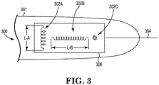
- FIG. 3 shows a sensor assembly 300 that can be used in tracking systems such as the tracking system 100 of FIG. 1 .
- the sensor assembly 300 is shown being positioned at a distal end of a probe 301, like the probe 108 of FIG. 1 .
- the sensor assembly 300 is shown as having three magnetic field sensors (i.e., a first magnetic field sensor 302A, a second magnetic field sensor 302B, and a third magnetic field sensor 302C), although is appreciated that the sensor assembly 300 could have only two magnetic field sensors or more than three magnetic field sensors.
- the magnetic field sensors 302A-C can be ordered in different arrangements.
- the magnetic field sensors in FIG. 3 are inductive sensing coils, which are arranged orthogonally to each other.
- the first magnetic field sensor 302A extends a length, L-A, in a direction that is perpendicular to a longitudinal axis 304 of the probe 301.
- the second magnetic field sensor 302B extends a length, L-B, in a direction parallel to the longitudinal axis 304.
- the length, L-B, of the second magnetic field sensor 302B is longer than the length, L-A, of the first magnetic field sensor 302A.
- the second magnetic field sensor 302B is at least 1.25 times longer than the first magnetic field sensor 302A.
- the second magnetic field sensor 302B is at least twice as long as the first magnetic field sensor 302A.
- the second magnetic field sensor 302B is at or between 1.25-2 times longer than the first magnetic field sensor 302A.
- the second magnetic field sensor 302B can be characterized as having a greater sensitivity to magnetic fields than the first magnetic field sensor's sensitivity. In other words, for a given magnetic field amplitude, the second magnetic field sensor 302B generates a larger responsive sensing signal, which is used to determine location and orientation of the sensor assembly 300.
- the magnetic field sensors 302A-C can be coupled together and oriented relative to each other by various means 306.
- the coupling and orientation means 306 includes suspending the magnetic field sensors 302A-C in an epoxy, potting, and the like.
- the coupling and orientation means 306 includes using injection molding to couple the various sensors.
- the sensing signals generated by the magnetic field sensors 302A-C can be transmitted from the sensing assembly 300 to a controller, such as the controller 106 of FIG. 1 , wirelessly or via one or more conductors.
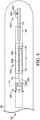
- FIG. 4 shows a sensor assembly 400 that can be used in tracking systems such as the tracking system 100 of FIG. 1 .
- the sensor assembly 400 is shown being positioned at a distal end of a probe 401, like the probe 108 of FIG. 1 .
- the sensor assembly 400 is shown as having three magnetic field sensors (i.e., a first magnetic field sensor 402A, a second magnetic field sensor 402B, and a third magnetic field sensor 402C), although is appreciated that the sensor assembly 400 could have only two magnetic field sensors or more than three magnetic field sensors.
- the magnetic field sensors 402A-C can be ordered in different arrangements.
- the magnetic field sensors in FIG. 4 are inductive sensing coils, which are arranged orthogonally to each other.
- the first magnetic field sensor 402A extends in a direction that is perpendicular to a longitudinal axis 404 of the probe 401 and has a number of windings, N-A.
- the second magnetic field sensor 402B extends a length in a direction parallel to the longitudinal axis 404 and has a number of windings, N-B.
- the second magnetic field sensor 402B has a greater number of windings, N-B than the number of windings, N-A, of the first magnetic field sensor 402A.
- the second magnetic field sensor 302B includes at least 1.25 times more windings than the first magnetic field sensor 302A.
- the second magnetic field sensor 302B includes at least two times more windings than the first magnetic field sensor 302A. In some embodiments, the second magnetic field sensor 302B includes 1.25-2 times more windings than the first magnetic field sensor 302A.
- the second magnetic field sensor 402B can be characterized as having a greater sensitivity to magnetic fields than the first magnetic field sensor's sensitivity. In other words, for a given magnetic field amplitude, the second magnetic field sensor 402B generates a larger responsive sensing signal, which is used to determine location and orientation of the sensor assembly 400.
- the magnetic field sensors 402A-C can be coupled together and oriented relative to each other by various means 406.
- the coupling and orientation means 406 includes suspending the magnetic field sensors 402A-C in an epoxy, potting, and the like.
- the coupling and orientation means 306 includes using injection molding to couple the various sensors.
- the sensing signals generated by the magnetic field sensors 402A-C can be transmitted from the sensing assembly 400 to a controller, such as the controller 106 of FIG. 1 , wirelessly or via one or more conductors.
- FIG. 5 shows a sensor assembly 500 that can be used in tracking systems such as the tracking system 100 of FIG. 1 .
- the sensor assembly 500 is shown being positioned at a distal end of a probe 501, like the probe 108 of FIG. 1 .
- the sensor assembly 500 is shown as having three magnetic field sensors (i.e., a first magnetic field sensor 502A, a second magnetic field sensor 502B, and a third magnetic field sensor 502C), although is appreciated that the sensor assembly 500 could have only two magnetic field sensors or more than three magnetic field sensors.
- the magnetic field sensors 502A-C can be ordered in different arrangements.
- the sensor assembly 500 is part of a flex circuit assembly.
- Each magnetic field sensor in FIG. 5 includes at least one elongated magnetic field sensor component, 504A, 504B, and 504C, which can be AMR sensing elements.
- the first magnetic field sensor 502A includes a first sensor substrate 506A
- the second magnetic field sensor 502B includes a second sensor substrate 506B
- the third magnetic field sensor 502C includes a third sensor substrate 506C.
- Each elongated magnetic field sensor component can be coupled to or positioned on its respective sensor substrate.
- the first magnetic field sensor 502A and the second magnetic field sensor 502B are shown being positioned on a common sensor assembly substrate 508, which can form part of a flex circuit.
- the third magnetic field sensor 502C is shown being positioned on another sensor assembly substrate 510, which is coupled to the common sensor assembly substrate 508, is oriented perpendicular to the common sensor assembly substrate 508, and can form part of a flex circuit.
- the AMR sensing elements, 504A-C each has an associated length: L-A, L-B, etc.
- the first AMR sensing element 504A has a length, L-A, along an axis 512 that is perpendicular to a longitudinal axis 514 of the probe 501.
- the second AMR sensing element 504B in the second magnetic field sensor 502B has a length, L-B, along the longitudinal axis 514 of the probe 501.
- the length, L-B, of the second AMR sensing element 504B is longer than the length, L-A, of the first AMR sensing element 504A.
- the second magnetic field sensor 502B has an overall length that is longer than an overall length of the first magnetic field sensor 502A. Because of the longer AMR sensing element 504B, the second magnetic field sensor 502B can be characterized as having a greater sensitivity to magnetic fields than the first magnetic field sensor's sensitivity. In other words, for a given magnetic field amplitude, the second magnetic field sensor 502B generates a larger responsive sensing signal, which is used to determine location and orientation of the sensor assembly 500.
- FIG. 6 shows a sensor assembly 600 that can be used in tracking systems such as the tracking system 100 of FIG. 1 .
- the sensor assembly 600 is shown being positioned at a distal end of a probe 601, like the probe 108 of FIG. 1 .
- the sensor assembly 600 is shown as having four magnetic field sensors (i.e., a first magnetic field sensor 602A, a second magnetic field sensor 602B, a third magnetic field sensor 602C, and a fourth magnetic field sensor 602D), although is appreciated that the sensor assembly 600 could have only two magnetic field sensors or more than three magnetic field sensors.
- the magnetic field sensors 602A-C can be ordered in different arrangements.
- the sensor assembly 600 is part of a flex circuit assembly.
- the magnetic field sensors 602A-D can include sensors such as inductive sensing coils and/or various sensing elements such as MR sensing elements (e.g., AMR sensing elements, GMR sensing elements, TMR sensing elements, Hall effect sensing elements, CMR sensing elements, EMR sensing elements, spin Hall sensing elements, and the like), GMI sensing elements, and/or flux-gate sensing elements.
- MR sensing elements e.g., AMR sensing elements, GMR sensing elements, TMR sensing elements, Hall effect sensing elements, CMR sensing elements, EMR sensing elements, spin Hall sensing elements, and the like
- GMI sensing elements e.g., GMI sensing elements, and/or flux-gate sensing elements.
- FIG. 6 shows the first magnetic field sensor 602A positioned and oriented such that its primary sensing direction is along an axis 604 that is perpendicular to a longitudinal axis 606 of the probe 601.
- the second magnetic field sensor 602B is positioned and oriented such that its primary sensing direction is parallel to the longitudinal axis 606 of the probe 601.
- the third magnetic field sensor 602C is positioned and oriented such that its primary sensing direction is parallel to the longitudinal axis 606 of the probe 601.
- the fourth magnetic field sensor 602D is positioned and oriented along an axis that is orthogonal to the longitudinal axis 606 of the probe 601.
- first, second, and third magnetic field sensors 602A-C are shown as being positioned on common substrate 608, it is appreciated that the magnetic field sensors can be positioned on individual substrates, common substrates, or suspended in epoxy, potting, etc., without a substrate, and/or a combination of the same.
- the fourth magnetic field sensor 602D is shown being positioned on another sensor assembly substrate 610, which is coupled to the common sensor assembly substrate 608, is oriented perpendicular to the common sensor assembly substrate 608, and can form part of a flex circuit.
- the two magnetic field sensors can provide greater sensitivity compared to the sensitivity of the first and fourth magnetic field sensors, 602A and 602D.
- the second magnetic field sensor 202B and the third magnetic field sensor 202C generate a combined larger responsive sensing signal compared to the other magnetic field sensor's responsive sensing signals.
Landscapes
- Physics & Mathematics (AREA)
- Life Sciences & Earth Sciences (AREA)
- Engineering & Computer Science (AREA)
- Health & Medical Sciences (AREA)
- General Physics & Mathematics (AREA)
- Condensed Matter Physics & Semiconductors (AREA)
- Remote Sensing (AREA)
- Surgery (AREA)
- Animal Behavior & Ethology (AREA)
- Veterinary Medicine (AREA)
- Public Health (AREA)
- Human Computer Interaction (AREA)
- General Health & Medical Sciences (AREA)
- Biophysics (AREA)
- Pathology (AREA)
- Biomedical Technology (AREA)
- Heart & Thoracic Surgery (AREA)
- Medical Informatics (AREA)
- Molecular Biology (AREA)
- Electromagnetism (AREA)
- Geology (AREA)
- Environmental & Geological Engineering (AREA)
- Geophysics (AREA)
- General Life Sciences & Earth Sciences (AREA)
- Measuring Magnetic Variables (AREA)
- Hall/Mr Elements (AREA)
- Media Introduction/Drainage Providing Device (AREA)
Claims (11)
- Sensoranordnung (200), umfassend:einen ersten Magnetfeldsensor (202A), umfassend ein erstes Substrat (208A) und eine erste längliche Magnetfeldsensorkomponente (206A), die sich über eine erste Länge erstreckt; undeinen zweiten Magnetfeldsensor (202B), umfassend ein zweites Substrat (208B) und eine zweite längliche Magnetfeldsensorkomponente (206B), die sich über eine zweite Länge erstreckt, die kürzer als die erste Länge ist,wobei der erste Magnetfeldsensor (202A) eine größere Empfindlichkeit gegenüber einem erfassten Magnetfeld aufweist als der zweite Magnetfeldsensor (202B),wobei die erste längliche Magnetfeldsensorkomponente (206A) eine erste Flussführung ist, und wobei die zweite längliche Magnetfeldsensorkomponente (206B) eine zweite Flussführung ist,wobei der erste Magnetfeldsensor (202A) ein erstes magnetoresistives Sensorelement (204A) umfasst, das benachbart zu der ersten Flussführung positioniert ist, und wobei der zweite Magnetfeldsensor (202B) ein zweites magnetoresistives Sensorelement (204B) umfasst, das benachbart zu der zweiten Flussführung positioniert ist.
- Sensoranordnung (200) nach Anspruch 1, wobei das erste und das zweite magnetoresistive Sensorelement (204A, 204B) eines von riesenmagnetoresistiven Sensorelementen, tunnelmagnetoresistiven Sensorelementen, Hall-Effekt-Sensorelementen, kolossal magnetoresistiven Sensorelementen, außergewöhnlich magnetoresistiven Sensorelementen und Spin-Hall-Sensorelementen sind.
- Sensoranordnung (200) nach einem der Ansprüche 1-2, wobei der erste Magnetfeldsensor (202A) dazu ausgelegt ist, eine erste Komponente eines Magnetfelds entlang einer ersten Achse zu erfassen, wobei der zweite Magnetfeldsensor (202B) dazu ausgelegt ist, eine zweite Komponente des Magnetfelds entlang einer zweiten Achse zu erfassen.
- Sensoranordnung (200) nach einem der Ansprüche 1-3, wobei der erste Magnetfeldsensor (202A) und der zweite Magnetfeldsensor (202B) an ein gemeinsames Substrat gekoppelt sind.
- Sensoranordnung (200) nach einem der Ansprüche 1-4, ferner umfassend:
einen dritten Magnetfeldsensor (202C), umfassend ein drittes Substrat (208C) und eine dritte längliche Magnetfeldsensorkomponente (206C), die sich über eine dritte Länge erstreckt, die kürzer als die erste Länge ist. - Sensoranordnung (200) nach einem der Ansprüche 1-5, wobei der erste Magnetfeldsensor (202A) mindestens doppelt so empfindlich ist wie der zweite Magnetfeldsensor (202B).
- System (100), umfassend:einen Magnetfeldgenerator (104), dazu ausgelegt, ein Magnetfeld zu erzeugen; undeine Sonde (108) mit einer Längsachse und einer Sensoranordnung (102) nach Anspruch 1, positioniert an oder nahe einem distalen Ende der Sonde (108).
- System (100) nach Anspruch 7, wobei der erste Magnetfeldsensor (202A) dazu ausgelegt ist, eine erste Komponente des Magnetfelds entlang der Längsachse (216) zu erfassen, wobei der zweite Magnetfeldsensor (202B) dazu ausgelegt ist, eine zweite Komponente des Magnetfelds entlang einer zweiten Achse zu erfassen, und wobei der erste Magnetsensor (202A) eine größere Empfindlichkeit gegenüber der ersten Komponente des Magnetfelds als eine Empfindlichkeit des zweiten Magnetfeldsensors (202B) gegenüber der zweiten Komponente des Magnetfelds aufweist.
- System (100) nach einem der Ansprüche 7-8, wobei der erste Magnetfeldsensor (202A) ein erstes magnetoresistives Sensorelement umfasst, wobei der zweite Magnetfeldsensor (202B) ein zweites magnetoresistives Sensorelement umfasst, wobei das erste magnetoresistive Sensorelement länger als das zweite magnetoresistive Sensorelement ist.
- System (100) nach einem der Ansprüche 7-9, wobei der erste und zweite Magnetfeldsensor (202A, 202B) einer von riesenmagnetoresistiven Sensorelementen, tunnelmagnetoresistiven Sensorelementen, Hall-Effekt-Sensorelementen, kolossal magnetoresistiven Sensorelementen, außergewöhnlich magnetoresistiven Sensorelementen und Spin-Hall-Sensorelementen sind.
- System (100) nach einem der Ansprüche 7-10, ferner umfassend:
einen dritten Magnetfeldsensor (202C), dazu ausgelegt, eine dritte Komponente des Magnetfelds entlang einer dritten Achse zu erfassen, die sich von der Längsachse (216) und der zweiten Achse unterscheidet.
Applications Claiming Priority (2)
| Application Number | Priority Date | Filing Date | Title |
|---|---|---|---|
| US201662436418P | 2016-12-19 | 2016-12-19 | |
| PCT/US2017/067111 WO2018118814A1 (en) | 2016-12-19 | 2017-12-18 | Dominant axis navigation sensor |
Publications (2)
| Publication Number | Publication Date |
|---|---|
| EP3555565A1 EP3555565A1 (de) | 2019-10-23 |
| EP3555565B1 true EP3555565B1 (de) | 2021-09-08 |
Family
ID=60943157
Family Applications (1)
| Application Number | Title | Priority Date | Filing Date |
|---|---|---|---|
| EP17826400.8A Not-in-force EP3555565B1 (de) | 2016-12-19 | 2017-12-18 | Navigationssensor mit dominanter achse |
Country Status (5)
| Country | Link |
|---|---|
| US (1) | US20180172865A1 (de) |
| EP (1) | EP3555565B1 (de) |
| JP (1) | JP2020513882A (de) |
| CN (1) | CN110088571A (de) |
| WO (1) | WO2018118814A1 (de) |
Families Citing this family (5)
| Publication number | Priority date | Publication date | Assignee | Title |
|---|---|---|---|---|
| US10782114B2 (en) | 2016-12-20 | 2020-09-22 | Boston Scientific Scimed Inc. | Hybrid navigation sensor |
| US11058321B2 (en) | 2016-12-20 | 2021-07-13 | Boston Scientific Scimed Inc. | Current driven sensor for magnetic navigation |
| EP3576622B1 (de) | 2017-02-06 | 2025-11-19 | Boston Scientific Scimed Inc. | Sensoranordnungen für elektromagnetische navigationssysteme |
| KR20230061378A (ko) * | 2020-08-04 | 2023-05-08 | 멜지 코퍼레이션 | 금속 검출 장치 및 그 오퍼레이션의 방법 |
| WO2023244703A1 (en) | 2022-06-17 | 2023-12-21 | Boston Scientific Scimed, Inc. | Medical device position sensing components |
Family Cites Families (12)
| Publication number | Priority date | Publication date | Assignee | Title |
|---|---|---|---|---|
| EP1892538A3 (de) * | 1999-06-18 | 2008-08-13 | Koninklijke Philips Electronics N.V. | Magnetische Systeme mit unumkehrbaren Eigenschaften und Verfahren zur Herstellung, zur Wiederherstellung und zum Betrieb derartiger Systeme |
| US6484118B1 (en) * | 2000-07-20 | 2002-11-19 | Biosense, Inc. | Electromagnetic position single axis system |
| JP2003069109A (ja) * | 2001-08-30 | 2003-03-07 | Sony Corp | 磁気抵抗効果型磁気センサ、磁気抵抗効果型磁気ヘッド、磁気再生装置と、磁気抵抗効果型磁気センサおよび磁気抵抗効果型磁気ヘッドの製造方法 |
| US7301332B2 (en) * | 2005-10-06 | 2007-11-27 | Biosense Webster, Inc. | Magnetic sensor assembly |
| US7870678B2 (en) * | 2006-09-06 | 2011-01-18 | Samsung Electro-Mechanics Co., Ltd. | Hybrid sensor module and sensing method using the same |
| WO2010117363A1 (en) * | 2009-04-09 | 2010-10-14 | Michelin Recherche Et Technique, S.A. | Tire metallic cable anomaly detection method and apparatus |
| US8706193B2 (en) * | 2009-06-22 | 2014-04-22 | Biosense Webster, Inc. | Catheter with obliquely-oriented coils |
| US9427172B2 (en) * | 2011-12-30 | 2016-08-30 | Mediguide Ltd. | Roll detection and six degrees of freedom sensor assembly |
| US10966629B2 (en) * | 2014-12-01 | 2021-04-06 | Koninklijke Philips N.V. | Virtually-oriented electromagnetic tracking coil for catheter based navigation |
| US9857438B2 (en) * | 2015-04-20 | 2018-01-02 | Infineon Technologies Ag | Magnetoresistive devices |
| JP2018524054A (ja) * | 2015-06-03 | 2018-08-30 | セント・ジュード・メディカル・インターナショナル・ホールディング・エスエーアールエルSt. Jude Medical International Holding S.a,r.l. | 能動型磁気位置センサ |
| CN105911490B (zh) * | 2016-05-12 | 2018-06-15 | 美新半导体(无锡)有限公司 | 具有自检重置导线的磁场传感器 |
-
2017
- 2017-12-18 JP JP2019532949A patent/JP2020513882A/ja active Pending
- 2017-12-18 US US15/845,901 patent/US20180172865A1/en not_active Abandoned
- 2017-12-18 EP EP17826400.8A patent/EP3555565B1/de not_active Not-in-force
- 2017-12-18 CN CN201780078560.0A patent/CN110088571A/zh active Pending
- 2017-12-18 WO PCT/US2017/067111 patent/WO2018118814A1/en not_active Ceased
Also Published As
| Publication number | Publication date |
|---|---|
| CN110088571A (zh) | 2019-08-02 |
| WO2018118814A1 (en) | 2018-06-28 |
| JP2020513882A (ja) | 2020-05-21 |
| EP3555565A1 (de) | 2019-10-23 |
| US20180172865A1 (en) | 2018-06-21 |
Similar Documents
| Publication | Publication Date | Title |
|---|---|---|
| US10782114B2 (en) | Hybrid navigation sensor | |
| US11058321B2 (en) | Current driven sensor for magnetic navigation | |
| EP3555565A1 (de) | Navigationssensor mit dominanter achse | |
| US10835151B2 (en) | Sensor assemblies for electromagnetic navigation systems | |
| US9360533B2 (en) | Reading circuit for a magnetic field sensor with sensititivy calibration, and related reading method | |
| JP6508163B2 (ja) | 電流測定装置 | |
| US20180220928A1 (en) | Sensor assemblies for electromagnetic navigation systems | |
| US7650178B2 (en) | Magnetic field sensor-based navigation system to track MR image-guided interventional procedures | |
| CN109414212B (zh) | 生物磁测量装置 | |
| JP5897719B2 (ja) | 磁気抵抗センサ、グラジオメータ | |
| JP6710747B2 (ja) | 位置追跡システム | |
| US20040143183A1 (en) | Device for detecting a position and an orientation of a medical insertion tool inside a body cavity, and detecting method therefor | |
| KR20080031929A (ko) | 중재적 디바이스 위치 측정을 위한 감지기의 자기 추적을위한 시스템 및 방법 | |
| EP3282943A1 (de) | Aktiver magnetischer positionssensor | |
| US12038757B2 (en) | Marker detection system and method of operating marker detection system | |
| US20180220927A1 (en) | Electromagnetic navigation system with magneto-resistive sensors and application-specific integrated circuits | |
| US11759117B2 (en) | Surgical ferromagnetic object detection system and method | |
| CN108872887B (zh) | 磁场补偿装置 | |
| JP7273876B2 (ja) | 磁気センサ装置、インバータ装置およびバッテリ装置 | |
| US20180220926A1 (en) | Electromagnetic navigation system with magneto-resistive sensors and application-specific integrated circuits | |
| US10076267B2 (en) | Methods and systems for improved navigation | |
| EP4732804A2 (de) | Magnetoresistives spulensensor-verfolgungssystem | |
| Ren et al. | Design of a data acquisition system on magnetic signal for magnetic localization and orientation system | |
| Zeng et al. | An analytic algorithm based position and orientation detection using a tri-axial magnetoresistive sensor |
Legal Events
| Date | Code | Title | Description |
|---|---|---|---|
| STAA | Information on the status of an ep patent application or granted ep patent |
Free format text: STATUS: UNKNOWN |
|
| STAA | Information on the status of an ep patent application or granted ep patent |
Free format text: STATUS: THE INTERNATIONAL PUBLICATION HAS BEEN MADE |
|
| PUAI | Public reference made under article 153(3) epc to a published international application that has entered the european phase |
Free format text: ORIGINAL CODE: 0009012 |
|
| STAA | Information on the status of an ep patent application or granted ep patent |
Free format text: STATUS: REQUEST FOR EXAMINATION WAS MADE |
|
| 17P | Request for examination filed |
Effective date: 20190709 |
|
| AK | Designated contracting states |
Kind code of ref document: A1 Designated state(s): AL AT BE BG CH CY CZ DE DK EE ES FI FR GB GR HR HU IE IS IT LI LT LU LV MC MK MT NL NO PL PT RO RS SE SI SK SM TR |
|
| AX | Request for extension of the european patent |
Extension state: BA ME |
|
| DAV | Request for validation of the european patent (deleted) | ||
| DAX | Request for extension of the european patent (deleted) | ||
| RIC1 | Information provided on ipc code assigned before grant |
Ipc: A61B 5/06 20060101ALI20200727BHEP Ipc: G01C 21/00 20060101AFI20200727BHEP Ipc: G01R 33/00 20060101ALI20200727BHEP Ipc: G01R 33/09 20060101ALI20200727BHEP |
|
| GRAP | Despatch of communication of intention to grant a patent |
Free format text: ORIGINAL CODE: EPIDOSNIGR1 |
|
| STAA | Information on the status of an ep patent application or granted ep patent |
Free format text: STATUS: GRANT OF PATENT IS INTENDED |
|
| INTG | Intention to grant announced |
Effective date: 20201008 |
|
| GRAJ | Information related to disapproval of communication of intention to grant by the applicant or resumption of examination proceedings by the epo deleted |
Free format text: ORIGINAL CODE: EPIDOSDIGR1 |
|
| STAA | Information on the status of an ep patent application or granted ep patent |
Free format text: STATUS: REQUEST FOR EXAMINATION WAS MADE |
|
| INTC | Intention to grant announced (deleted) | ||
| GRAS | Grant fee paid |
Free format text: ORIGINAL CODE: EPIDOSNIGR3 |
|
| STAA | Information on the status of an ep patent application or granted ep patent |
Free format text: STATUS: GRANT OF PATENT IS INTENDED |
|
| GRAP | Despatch of communication of intention to grant a patent |
Free format text: ORIGINAL CODE: EPIDOSNIGR1 |
|
| INTG | Intention to grant announced |
Effective date: 20210421 |
|
| RIN1 | Information on inventor provided before grant (corrected) |
Inventor name: VISWANATHAN, RAJU Inventor name: FOSTER, DANIEL J. Inventor name: HEIN, MATTHEW |
|
| GRAA | (expected) grant |
Free format text: ORIGINAL CODE: 0009210 |
|
| STAA | Information on the status of an ep patent application or granted ep patent |
Free format text: STATUS: THE PATENT HAS BEEN GRANTED |
|
| AK | Designated contracting states |
Kind code of ref document: B1 Designated state(s): AL AT BE BG CH CY CZ DE DK EE ES FI FR GB GR HR HU IE IS IT LI LT LU LV MC MK MT NL NO PL PT RO RS SE SI SK SM TR |
|
| REG | Reference to a national code |
Ref country code: GB Ref legal event code: FG4D |
|
| REG | Reference to a national code |
Ref country code: AT Ref legal event code: REF Ref document number: 1428968 Country of ref document: AT Kind code of ref document: T Effective date: 20210915 Ref country code: CH Ref legal event code: EP |
|
| REG | Reference to a national code |
Ref country code: IE Ref legal event code: FG4D |
|
| REG | Reference to a national code |
Ref country code: DE Ref legal event code: R096 Ref document number: 602017045791 Country of ref document: DE |
|
| REG | Reference to a national code |
Ref country code: LT Ref legal event code: MG9D |
|
| REG | Reference to a national code |
Ref country code: NL Ref legal event code: MP Effective date: 20210908 |
|
| PG25 | Lapsed in a contracting state [announced via postgrant information from national office to epo] |
Ref country code: RS Free format text: LAPSE BECAUSE OF FAILURE TO SUBMIT A TRANSLATION OF THE DESCRIPTION OR TO PAY THE FEE WITHIN THE PRESCRIBED TIME-LIMIT Effective date: 20210908 Ref country code: SE Free format text: LAPSE BECAUSE OF FAILURE TO SUBMIT A TRANSLATION OF THE DESCRIPTION OR TO PAY THE FEE WITHIN THE PRESCRIBED TIME-LIMIT Effective date: 20210908 Ref country code: HR Free format text: LAPSE BECAUSE OF FAILURE TO SUBMIT A TRANSLATION OF THE DESCRIPTION OR TO PAY THE FEE WITHIN THE PRESCRIBED TIME-LIMIT Effective date: 20210908 Ref country code: FI Free format text: LAPSE BECAUSE OF FAILURE TO SUBMIT A TRANSLATION OF THE DESCRIPTION OR TO PAY THE FEE WITHIN THE PRESCRIBED TIME-LIMIT Effective date: 20210908 Ref country code: ES Free format text: LAPSE BECAUSE OF FAILURE TO SUBMIT A TRANSLATION OF THE DESCRIPTION OR TO PAY THE FEE WITHIN THE PRESCRIBED TIME-LIMIT Effective date: 20210908 Ref country code: BG Free format text: LAPSE BECAUSE OF FAILURE TO SUBMIT A TRANSLATION OF THE DESCRIPTION OR TO PAY THE FEE WITHIN THE PRESCRIBED TIME-LIMIT Effective date: 20211208 Ref country code: LT Free format text: LAPSE BECAUSE OF FAILURE TO SUBMIT A TRANSLATION OF THE DESCRIPTION OR TO PAY THE FEE WITHIN THE PRESCRIBED TIME-LIMIT Effective date: 20210908 Ref country code: NO Free format text: LAPSE BECAUSE OF FAILURE TO SUBMIT A TRANSLATION OF THE DESCRIPTION OR TO PAY THE FEE WITHIN THE PRESCRIBED TIME-LIMIT Effective date: 20211208 |
|
| REG | Reference to a national code |
Ref country code: AT Ref legal event code: MK05 Ref document number: 1428968 Country of ref document: AT Kind code of ref document: T Effective date: 20210908 |
|
| PG25 | Lapsed in a contracting state [announced via postgrant information from national office to epo] |
Ref country code: LV Free format text: LAPSE BECAUSE OF FAILURE TO SUBMIT A TRANSLATION OF THE DESCRIPTION OR TO PAY THE FEE WITHIN THE PRESCRIBED TIME-LIMIT Effective date: 20210908 Ref country code: GR Free format text: LAPSE BECAUSE OF FAILURE TO SUBMIT A TRANSLATION OF THE DESCRIPTION OR TO PAY THE FEE WITHIN THE PRESCRIBED TIME-LIMIT Effective date: 20211209 |
|
| PG25 | Lapsed in a contracting state [announced via postgrant information from national office to epo] |
Ref country code: AT Free format text: LAPSE BECAUSE OF FAILURE TO SUBMIT A TRANSLATION OF THE DESCRIPTION OR TO PAY THE FEE WITHIN THE PRESCRIBED TIME-LIMIT Effective date: 20210908 |
|
| PG25 | Lapsed in a contracting state [announced via postgrant information from national office to epo] |
Ref country code: IS Free format text: LAPSE BECAUSE OF FAILURE TO SUBMIT A TRANSLATION OF THE DESCRIPTION OR TO PAY THE FEE WITHIN THE PRESCRIBED TIME-LIMIT Effective date: 20220108 Ref country code: SM Free format text: LAPSE BECAUSE OF FAILURE TO SUBMIT A TRANSLATION OF THE DESCRIPTION OR TO PAY THE FEE WITHIN THE PRESCRIBED TIME-LIMIT Effective date: 20210908 Ref country code: SK Free format text: LAPSE BECAUSE OF FAILURE TO SUBMIT A TRANSLATION OF THE DESCRIPTION OR TO PAY THE FEE WITHIN THE PRESCRIBED TIME-LIMIT Effective date: 20210908 Ref country code: RO Free format text: LAPSE BECAUSE OF FAILURE TO SUBMIT A TRANSLATION OF THE DESCRIPTION OR TO PAY THE FEE WITHIN THE PRESCRIBED TIME-LIMIT Effective date: 20210908 Ref country code: PT Free format text: LAPSE BECAUSE OF FAILURE TO SUBMIT A TRANSLATION OF THE DESCRIPTION OR TO PAY THE FEE WITHIN THE PRESCRIBED TIME-LIMIT Effective date: 20220110 Ref country code: PL Free format text: LAPSE BECAUSE OF FAILURE TO SUBMIT A TRANSLATION OF THE DESCRIPTION OR TO PAY THE FEE WITHIN THE PRESCRIBED TIME-LIMIT Effective date: 20210908 Ref country code: NL Free format text: LAPSE BECAUSE OF FAILURE TO SUBMIT A TRANSLATION OF THE DESCRIPTION OR TO PAY THE FEE WITHIN THE PRESCRIBED TIME-LIMIT Effective date: 20210908 Ref country code: EE Free format text: LAPSE BECAUSE OF FAILURE TO SUBMIT A TRANSLATION OF THE DESCRIPTION OR TO PAY THE FEE WITHIN THE PRESCRIBED TIME-LIMIT Effective date: 20210908 Ref country code: CZ Free format text: LAPSE BECAUSE OF FAILURE TO SUBMIT A TRANSLATION OF THE DESCRIPTION OR TO PAY THE FEE WITHIN THE PRESCRIBED TIME-LIMIT Effective date: 20210908 Ref country code: AL Free format text: LAPSE BECAUSE OF FAILURE TO SUBMIT A TRANSLATION OF THE DESCRIPTION OR TO PAY THE FEE WITHIN THE PRESCRIBED TIME-LIMIT Effective date: 20210908 |
|
| REG | Reference to a national code |
Ref country code: DE Ref legal event code: R097 Ref document number: 602017045791 Country of ref document: DE |
|
| PLBE | No opposition filed within time limit |
Free format text: ORIGINAL CODE: 0009261 |
|
| STAA | Information on the status of an ep patent application or granted ep patent |
Free format text: STATUS: NO OPPOSITION FILED WITHIN TIME LIMIT |
|
| PG25 | Lapsed in a contracting state [announced via postgrant information from national office to epo] |
Ref country code: MC Free format text: LAPSE BECAUSE OF FAILURE TO SUBMIT A TRANSLATION OF THE DESCRIPTION OR TO PAY THE FEE WITHIN THE PRESCRIBED TIME-LIMIT Effective date: 20210908 Ref country code: DK Free format text: LAPSE BECAUSE OF FAILURE TO SUBMIT A TRANSLATION OF THE DESCRIPTION OR TO PAY THE FEE WITHIN THE PRESCRIBED TIME-LIMIT Effective date: 20210908 |
|
| REG | Reference to a national code |
Ref country code: CH Ref legal event code: PL |
|
| 26N | No opposition filed |
Effective date: 20220609 |
|
| PG25 | Lapsed in a contracting state [announced via postgrant information from national office to epo] |
Ref country code: SI Free format text: LAPSE BECAUSE OF FAILURE TO SUBMIT A TRANSLATION OF THE DESCRIPTION OR TO PAY THE FEE WITHIN THE PRESCRIBED TIME-LIMIT Effective date: 20210908 |
|
| REG | Reference to a national code |
Ref country code: BE Ref legal event code: MM Effective date: 20211231 |
|
| PG25 | Lapsed in a contracting state [announced via postgrant information from national office to epo] |
Ref country code: LU Free format text: LAPSE BECAUSE OF NON-PAYMENT OF DUE FEES Effective date: 20211218 Ref country code: IE Free format text: LAPSE BECAUSE OF NON-PAYMENT OF DUE FEES Effective date: 20211218 |
|
| PG25 | Lapsed in a contracting state [announced via postgrant information from national office to epo] |
Ref country code: BE Free format text: LAPSE BECAUSE OF NON-PAYMENT OF DUE FEES Effective date: 20211231 |
|
| PG25 | Lapsed in a contracting state [announced via postgrant information from national office to epo] |
Ref country code: LI Free format text: LAPSE BECAUSE OF NON-PAYMENT OF DUE FEES Effective date: 20211231 Ref country code: CH Free format text: LAPSE BECAUSE OF NON-PAYMENT OF DUE FEES Effective date: 20211231 |
|
| PG25 | Lapsed in a contracting state [announced via postgrant information from national office to epo] |
Ref country code: IT Free format text: LAPSE BECAUSE OF FAILURE TO SUBMIT A TRANSLATION OF THE DESCRIPTION OR TO PAY THE FEE WITHIN THE PRESCRIBED TIME-LIMIT Effective date: 20210908 |
|
| PG25 | Lapsed in a contracting state [announced via postgrant information from national office to epo] |
Ref country code: CY Free format text: LAPSE BECAUSE OF FAILURE TO SUBMIT A TRANSLATION OF THE DESCRIPTION OR TO PAY THE FEE WITHIN THE PRESCRIBED TIME-LIMIT Effective date: 20210908 |
|
| PG25 | Lapsed in a contracting state [announced via postgrant information from national office to epo] |
Ref country code: HU Free format text: LAPSE BECAUSE OF FAILURE TO SUBMIT A TRANSLATION OF THE DESCRIPTION OR TO PAY THE FEE WITHIN THE PRESCRIBED TIME-LIMIT; INVALID AB INITIO Effective date: 20171218 |
|
| PGFP | Annual fee paid to national office [announced via postgrant information from national office to epo] |
Ref country code: GB Payment date: 20231121 Year of fee payment: 7 |
|
| PGFP | Annual fee paid to national office [announced via postgrant information from national office to epo] |
Ref country code: FR Payment date: 20231122 Year of fee payment: 7 Ref country code: DE Payment date: 20231121 Year of fee payment: 7 |
|
| PG25 | Lapsed in a contracting state [announced via postgrant information from national office to epo] |
Ref country code: MK Free format text: LAPSE BECAUSE OF FAILURE TO SUBMIT A TRANSLATION OF THE DESCRIPTION OR TO PAY THE FEE WITHIN THE PRESCRIBED TIME-LIMIT Effective date: 20210908 |
|
| PG25 | Lapsed in a contracting state [announced via postgrant information from national office to epo] |
Ref country code: MT Free format text: LAPSE BECAUSE OF FAILURE TO SUBMIT A TRANSLATION OF THE DESCRIPTION OR TO PAY THE FEE WITHIN THE PRESCRIBED TIME-LIMIT Effective date: 20210908 |
|
| REG | Reference to a national code |
Ref country code: DE Ref legal event code: R119 Ref document number: 602017045791 Country of ref document: DE |
|
| GBPC | Gb: european patent ceased through non-payment of renewal fee |
Effective date: 20241218 |
|
| PG25 | Lapsed in a contracting state [announced via postgrant information from national office to epo] |
Ref country code: DE Free format text: LAPSE BECAUSE OF NON-PAYMENT OF DUE FEES Effective date: 20250701 |
|
| PG25 | Lapsed in a contracting state [announced via postgrant information from national office to epo] |
Ref country code: GB Free format text: LAPSE BECAUSE OF NON-PAYMENT OF DUE FEES Effective date: 20241218 |
|
| PG25 | Lapsed in a contracting state [announced via postgrant information from national office to epo] |
Ref country code: FR Free format text: LAPSE BECAUSE OF NON-PAYMENT OF DUE FEES Effective date: 20241231 |
|
| PG25 | Lapsed in a contracting state [announced via postgrant information from national office to epo] |
Ref country code: TR Free format text: LAPSE BECAUSE OF FAILURE TO SUBMIT A TRANSLATION OF THE DESCRIPTION OR TO PAY THE FEE WITHIN THE PRESCRIBED TIME-LIMIT Effective date: 20210908 |