EP3555512B1 - Method of manufacturing a male tube fitting and tube assembly comprising a male tube fitting - Google Patents
Method of manufacturing a male tube fitting and tube assembly comprising a male tube fitting Download PDFInfo
- Publication number
- EP3555512B1 EP3555512B1 EP18749371.3A EP18749371A EP3555512B1 EP 3555512 B1 EP3555512 B1 EP 3555512B1 EP 18749371 A EP18749371 A EP 18749371A EP 3555512 B1 EP3555512 B1 EP 3555512B1
- Authority
- EP
- European Patent Office
- Prior art keywords
- tube fitting
- friction
- male tube
- layer
- male
- Prior art date
- Legal status (The legal status is an assumption and is not a legal conclusion. Google has not performed a legal analysis and makes no representation as to the accuracy of the status listed.)
- Active
Links
Images

Classifications
-
- F—MECHANICAL ENGINEERING; LIGHTING; HEATING; WEAPONS; BLASTING
- F16—ENGINEERING ELEMENTS AND UNITS; GENERAL MEASURES FOR PRODUCING AND MAINTAINING EFFECTIVE FUNCTIONING OF MACHINES OR INSTALLATIONS; THERMAL INSULATION IN GENERAL
- F16L—PIPES; JOINTS OR FITTINGS FOR PIPES; SUPPORTS FOR PIPES, CABLES OR PROTECTIVE TUBING; MEANS FOR THERMAL INSULATION IN GENERAL
- F16L19/00—Joints in which sealing surfaces are pressed together by means of a member, e.g. a swivel nut, screwed on, or into, one of the joint parts
- F16L19/02—Pipe ends provided with collars or flanges, integral with the pipe or not, pressed together by a screwed member
- F16L19/025—Pipe ends provided with collars or flanges, integral with the pipe or not, pressed together by a screwed member the pipe ends having integral collars or flanges
- F16L19/028—Pipe ends provided with collars or flanges, integral with the pipe or not, pressed together by a screwed member the pipe ends having integral collars or flanges the collars or flanges being obtained by deformation of the pipe wall
-
- B—PERFORMING OPERATIONS; TRANSPORTING
- B60—VEHICLES IN GENERAL
- B60T—VEHICLE BRAKE CONTROL SYSTEMS OR PARTS THEREOF; BRAKE CONTROL SYSTEMS OR PARTS THEREOF, IN GENERAL; ARRANGEMENT OF BRAKING ELEMENTS ON VEHICLES IN GENERAL; PORTABLE DEVICES FOR PREVENTING UNWANTED MOVEMENT OF VEHICLES; VEHICLE MODIFICATIONS TO FACILITATE COOLING OF BRAKES
- B60T17/00—Component parts, details, or accessories of power brake systems not covered by groups B60T8/00, B60T13/00 or B60T15/00, or presenting other characteristic features
- B60T17/04—Arrangements of piping, valves in the piping, e.g. cut-off valves, couplings or air hoses
- B60T17/043—Brake line couplings, air hoses and stopcocks
-
- F—MECHANICAL ENGINEERING; LIGHTING; HEATING; WEAPONS; BLASTING
- F02—COMBUSTION ENGINES; HOT-GAS OR COMBUSTION-PRODUCT ENGINE PLANTS
- F02M—SUPPLYING COMBUSTION ENGINES IN GENERAL WITH COMBUSTIBLE MIXTURES OR CONSTITUENTS THEREOF
- F02M55/00—Fuel-injection apparatus characterised by their fuel conduits or their venting means; Arrangements of conduits between fuel tank and pump F02M37/00
- F02M55/004—Joints; Sealings
- F02M55/005—Joints; Sealings for high pressure conduits, e.g. connected to pump outlet or to injector inlet
-
- F—MECHANICAL ENGINEERING; LIGHTING; HEATING; WEAPONS; BLASTING
- F02—COMBUSTION ENGINES; HOT-GAS OR COMBUSTION-PRODUCT ENGINE PLANTS
- F02M—SUPPLYING COMBUSTION ENGINES IN GENERAL WITH COMBUSTIBLE MIXTURES OR CONSTITUENTS THEREOF
- F02M55/00—Fuel-injection apparatus characterised by their fuel conduits or their venting means; Arrangements of conduits between fuel tank and pump F02M37/00
- F02M55/02—Conduits between injection pumps and injectors, e.g. conduits between pump and common-rail or conduits between common-rail and injectors
- F02M55/025—Common rails
-
- F—MECHANICAL ENGINEERING; LIGHTING; HEATING; WEAPONS; BLASTING
- F16—ENGINEERING ELEMENTS AND UNITS; GENERAL MEASURES FOR PRODUCING AND MAINTAINING EFFECTIVE FUNCTIONING OF MACHINES OR INSTALLATIONS; THERMAL INSULATION IN GENERAL
- F16L—PIPES; JOINTS OR FITTINGS FOR PIPES; SUPPORTS FOR PIPES, CABLES OR PROTECTIVE TUBING; MEANS FOR THERMAL INSULATION IN GENERAL
- F16L19/00—Joints in which sealing surfaces are pressed together by means of a member, e.g. a swivel nut, screwed on, or into, one of the joint parts
- F16L19/02—Pipe ends provided with collars or flanges, integral with the pipe or not, pressed together by a screwed member
- F16L19/025—Pipe ends provided with collars or flanges, integral with the pipe or not, pressed together by a screwed member the pipe ends having integral collars or flanges
- F16L19/028—Pipe ends provided with collars or flanges, integral with the pipe or not, pressed together by a screwed member the pipe ends having integral collars or flanges the collars or flanges being obtained by deformation of the pipe wall
- F16L19/0286—Pipe ends provided with collars or flanges, integral with the pipe or not, pressed together by a screwed member the pipe ends having integral collars or flanges the collars or flanges being obtained by deformation of the pipe wall and being formed as a flange
Definitions
- the present invention relates to a method of manufacturing a male tube fitting, particularly to a male tube nut, and to a tube assembly, particularly a brake tubing or a fuel tubing for a motor vehicle, wherein the tube assembly comprises a male tube fitting.
- Hydraulic braking systems and male tube fittings are generally known and standardized for example according to ISO 4038 and to DIN 74233-1.
- Male tube fittings are used to connect a tube to a counterpart in a brake system of a motor vehicle.
- Conventional male tube fittings have an external thread and a passage extending in the axial direction for receiving the tube. This passage is commonly, and in this text, referred to as a through-hole.
- the tube is inserted into the passage in such a way that the flared tube end is brought into contact with a contact surface of the male tube fitting.
- the male tube fitting including the tube is screwed into an opening of the receiving counterpart or into a connecting member.
- the design of the flared end is similarly standardized, for example in accordance with DIN 74 234:1992-09 or SAE J2879.
- EP 2 706 277 A2 discloses a male tube fitting with a thread section and an end section.
- the thread section and the end section are coated with a friction-reducing layer.
- the end section is provided with a second layer in order to avoid the storage of torsional energy or deformation when screwing the male tube fitting into the opening of the receiving counterpart.
- the male tube fitting can be heated to dry and cure the first layer.
- the first layer can be subjected to thermal treatment or modification in order to achieve a thermal destruction of the first layer in parts, leading to a higher friction coefficient.
- EP 2 952 796 A1 discloses a male tube fitting having an inner layer and an outer layer.
- the outer layer includes a polymer and nanoparticles of solid matter and covers the entire surface of the male tube fitting.
- the inner layer is only applied to contact surfaces of the male tube fitting that come into contact with a tube or a connecting block.
- Another male tube fitting is disclosed in DE 20 2017 104 112 U1 .
- This male tube fitting includes a zinc nickel coating serving as an anti-corrosion coating.
- the anti-corrosion coating can be passivated by application of a passivation coating on the anti-corrosion coating.
- first and second coatings are applied to the male tube fitting, wherein the first coating covers the entire surface of the male tube fitting and the second coating is only applied to a contact surface at an end surface of the male tube fitting.
- the object is achieved by a method of manufacturing a male tube fitting according to claim 1 and by a tube assembly according to claim 11.
- Advantageous embodiments of the method are subject-matter of claims 2 to 10.
- the method of manufacturing a male tube fitting, particularly a male tube nut comprises the following steps:
- the modulation of friction applied to the friction-reducing layer By the modulation of friction applied to the friction-reducing layer, the quantity or amount of organic constituents in the friction-reducing layer is reduced, leading to a higher friction coefficient in some selected places of the friction-reducing layer, in particular in the region of the threaded section.
- the modulation improves the properties of the friction-reducing layer with respect to joint robustness, which is increased whilst minimizing deformation of the flared tube end.
- the inorganic constituents namely the silicates
- the inorganic constituents are largely unaffected by the modulation so that the additional anti-corrosion protection provided by them is still available.
- the inorganic constituents are harder than the organic constituents so that also the wear properties of the friction-reducing layer are maintained.
- the modulation of friction is conducted using a plasma treatment for the purpose of breaking up molecules in the friction-reducing layer.
- Plasma treatment allows a modification of the structure of both the friction-reducing layer and the anti-corrosion layer. This is done with a beam of oxygen ions generated by an open-air plasma system. Thereby, organic molecular chains in the friction-reducing layer are "cracked” into CO and CO 2 compounds, and the organic constituents, for instance organic waxes, are removed or stripped out from the friction-reducing layer.
- the male tube fitting is subjected to cooling, in particular active cooling at selected places, during the plasma treatment.
- cooling in particular active cooling at selected places
- the choice of a particular plasma setting that is advantageous for obtaining a high friction coefficient at the selected section, for instance the threaded section, may also lead to an undesired increase of the friction coefficient at undesirable places, for instance the contact section.
- Another option which is not part of the present invention, is to conduct the modulation of friction using a laser treatment for the purpose of breaking up molecules in the friction-reducing layer, whereby both organic and inorganic constituents are affected indiscriminately.
- the anti-corrosion layer is applied by immersing the male tube fitting into a bath solution.
- the friction-reducing layer is preferably applied by immersing the male tube fitting into a bath solution. This allows the bulk application of the layers to male tube fittings so that manufacturing the male tube fittings is conducted in an efficient manner.
- the male tube fitting is preferably subjected to centrifugal spin and heat to ensure an even distribution of the cured layer after application.
- the anti-corrosion layer is applied by galvanization, wherein preferably after step b), the anti-corrosion layer is passivated.
- a passivation is a chemical modification of the anti-corrosion layer. In that way, the anti-corrosion properties of the anti-corrosion layer are further improved.
- the passivation can particularly be conducted by immersing the male tube fitting into electrolytes.
- the anti-corrosion layer is preferably a galvanically-applied Zn or ZnNi alloy layer, or a dip-spin-applied zinc-flake or zinc-aluminium-flake layer, referred herein to the zinc-flake layer.
- the zinc-flake layer is an anti-corrosion layer including a multitude of zinc flakes and usually consisting of a combination of zinc and aluminium flakes which are compounded by an inorganic matrix. When the layer is applied, no hydrogen is produced. Thus, the risk of hydrogen induced stress corrosion cracking is avoided, particularly in the case of high-tensile steel.
- the thickness of the male tube fitting is at least partially reduced at the through-hole, wherein preferably the thickness is reduced so as to form a runout.
- an ultraviolet (UV) fluorescence value at the surface of the male tube fitting is measured to determine the content of organic constituents in the friction reducing layer.
- the fluorescence value can be determined due to the fluorescence of organic constituents.
- fluorescence is a special form of luminescence. Fluorescence is excited by radiation in an ultraviolet range. When electrons of fluorescing molecules absorb photons, they reach a higher level of energy. However, such an excited state is energetically instable. The electrons, therefore, return to their initial condition, thereby causing the previously absorbed energy to be released once again. This release of energy results in the emission of fluorescent light. Usually, some of the energy is transformed into heat so that the emitted radiation has less energy and, consequently, a longer wavelength.
- the fluorescence value can be measured by a detector which uses the so-called confocal measuring principle.
- Organic constituents are excited by a light emitting diode (LED) with light in an ultraviolet range.
- the fluorescence intensity depends on the amount of organic constituents at the measuring point.
- a photodiode measures the intensity of the fluorescence.
- the tube assembly according to the invention is particularly a brake tubing or a fuel tubing for a motor vehicle.
- the tube assembly comprises: a fluid-carrying tube, a connecting member having an internal thread and a male tube fitting configured in accordance with the method according to the invention.
- the external thread of the male tube fitting is configured to engage with the internal thread of the connecting member.
- the tube assembly in accordance with the present invention comprises an especially high friction coefficient in selected areas, in particular in the threaded section.
- the passivation is applied to the anti-corrosion layer before application of the friction reducing layer to the male tube fitting.
- the passivation is a chemical modification of the anti-corrosion layer in order to further improve the anti-corrosion properties.
- the anti-corrosion layer of the male tube fitting is a galvanically-applied Zn or ZnNi alloy layer, or a dip-spin-applied zinc-flake layer.
- the male tube fitting is made of metal, particularly of steel.
- a male tube fitting 10 manufactured in accordance with the method according to the present invention.
- the male tube fitting 10 comprises a head section 11 for applying a tightening torque to the male tube fitting 10, a threaded section 12 having an external thread 15, a contact section 13 having a contact face 16 and a through-hole 17, which extends in an axial direction As of the male tube fitting 10.
- an anti-corrosion layer 20 is first applied to the male tube fitting 10.
- a friction-reducing layer 30 is applied to the male tube fitting 10 to obtain a first friction coefficient ⁇ 1 .
- the friction-reducing layer 30 is friction modulated, at least in the threaded section 12.
- the male tube fitting 10 comprises two layers 20, 30, namely the anti-corrosion layer 20 to protect the male tube fitting 10 from corrosion and the friction-reducing layer 30 to reduce friction on the surface of the male tube fitting 10.
- the friction-reducing layer 30 is not homogenous, but comprises selected places, i. e. in particular in the threaded section 12, which have a higher friction coefficient ⁇ 2 than the friction coefficient ⁇ 1 in the remainder of the friction-reducing layer 30.
- the anti-corrosion layer 20 can be a galvanically-applied Zn or ZnNi alloy layer, or a dip-spin-applied zinc-flake layer.
- the galvanically-applied layer is a 12 % Ni alloy layer.
- the friction-reducing layer 30 comprises organic and inorganic constituents.
- Organic constituents are particularly waxes and polymers such as polyethylene (PE).
- Inorganic constituents are particularly silicates. Silicates predominantly serve for anti-corrosion protection.
- the male tube fitting 10 Due to the friction-reducing layer 30, the male tube fitting 10 has a first friction coefficient ⁇ 1 .
- a modulation of friction is applied to the friction-reducing layer 30 by breaking up molecules in the friction-reducing layer 30.
- organic constituents in the friction-reducing layer 30 are considerably reduced in relation to the inorganic constituents so that the threaded section 12 has a second friction coefficient ⁇ 2 .
- the second friction coefficient ⁇ 2 is higher than the first friction coefficient ⁇ 1 .
- Either a plasma treatment or, alternatively, a laser treatment can be conducted in order to break up the molecules in the in the friction-reducing layer 30.
- the plasma treatment is more advantageous and, therefore, this invention makes use of the plasma treatment.
- the plasma can be generated through a high-voltage discharge or, according to the invention, with a stream or beam of oxygen ions generated by an open-air plasma system.
- Fig. 3a illustrates the effect that a particular plasma setting has on the friction coefficient ⁇ 2 at the threaded section 12
- Fig. 3b illustrates the effect that the same plasma setting has on the friction coefficient ⁇ 1 at the contact section 13.
- the plasma settings 0 to 4 shown in both Fig. 3a and 3b refer to the plasma.
- the male tube fitting 10 can be subjected to a cooling, particularly to an active cooling at selected places, during the plasma treatment.
- the modulation of friction by open-air plasma further allows keeping the inorganic constituents, namely the silicates, intact.
- the additional anti-corrosion protection provided by them is still available.
- the inorganic constituents are also harder than the organic constituents so that also the wear properties of the friction-reducing layer are maintained.
- an ultraviolet (UV) fluorescence value at the surface of the male tube fitting 10 is measured to determine the content of organic constituents in the friction reducing layer 30.
- the UV fluorescence value dropped by the modulation of friction from an average of 3309 units to 1116 units.
- the thickness t A of the anti-corrosion layer 20 of a galvanically applied Zn or Zn-AI alloy layer is partially reduced in the through-hole 17. Thereupon, the addition of a mixed organic and inorganic sealer ensures that this reduction does not affect the corrosion resistance of the male tube fitting.
- FIG. 2a, 2b there are shown embodiments of a tube assembly 60 according to the invention with a male tube fitting 10 manufactured in accordance with the method described above.
- the tube assembly 60 comprises a connecting member 50 having an inner thread 51. Furthermore, a fluid-carrying tube 40 is provided.
- the fluid-carrying tube 40 has an abutment face 41 formed by a flared end 42. Flared ends 42 of tubes 40 are standardized.
- Fig. 2a shows a flared end 42 having form F according to DIN 74 234:1992-09
- Fig. 2b shows a flared end 42 having form E.
- the flared end 42 is in contact with the connecting member 50.
- the fluid-carrying tube 40 is received in the through-hole 17 of the male tube fitting 10 in such a way that the contact face 16 of the male tube fitting 10 contacts the abutment face 41 of the fluid-carrying tube 40.
- the male tube fitting 10 with the fluid-carrying tube 40 received in the through-hole 17 is screwed into the connecting member 50.
- the external thread 15 present in the threaded section 12 of the male tube fitting 10 is in engagement with the inner thread 51 of the connecting member 50.
- the male tube fitting 10 presses the fluid-carrying tube 40 against the connecting member 50 so that the fluid-carrying tube 40 is axially locked.
- the axial direction As of the male tube fitting 10 becomes coaxial with the axial direction Ap of the tube assembly 60.
- a first friction coefficient ⁇ 1 is achieved. This is advantageous, particularly in the area where the contact face 16 of the male tube fitting 10 contacts the abutment face 41 of the fluid-carrying tube 40.
- torsional load is applied to the fluid-carrying tube 40.
- the reduction of friction is particularly necessary in the area around the contact face 16, which is done by applying the friction-reducing layer 30.
- the organic constituents in the friction-reducing layer 30 are reduced so that a second friction coefficient ⁇ 2 higher than the first friction coefficient ⁇ 1 is achieved.
- the male tube fitting 10 and the tube assembly 60 shown in the drawings have in common that they reduce the friction in the area of the external thread 15 and therefore simplify the screwing of the male tube fitting 10 into the connecting member 50.
Landscapes
- Engineering & Computer Science (AREA)
- General Engineering & Computer Science (AREA)
- Mechanical Engineering (AREA)
- Chemical & Material Sciences (AREA)
- Combustion & Propulsion (AREA)
- Transportation (AREA)
- Rigid Pipes And Flexible Pipes (AREA)
- Non-Disconnectible Joints And Screw-Threaded Joints (AREA)
Description
- The present invention relates to a method of manufacturing a male tube fitting, particularly to a male tube nut, and to a tube assembly, particularly a brake tubing or a fuel tubing for a motor vehicle, wherein the tube assembly comprises a male tube fitting.
- Hydraulic braking systems and male tube fittings are generally known and standardized for example according to ISO 4038 and to DIN 74233-1. Male tube fittings are used to connect a tube to a counterpart in a brake system of a motor vehicle. Conventional male tube fittings have an external thread and a passage extending in the axial direction for receiving the tube. This passage is commonly, and in this text, referred to as a through-hole. In order to fix the tube provided with a flared end to a receiving counterpart of the brake system, the tube is inserted into the passage in such a way that the flared tube end is brought into contact with a contact surface of the male tube fitting. Subsequently, the male tube fitting including the tube is screwed into an opening of the receiving counterpart or into a connecting member. The design of the flared end is similarly standardized, for example in accordance with DIN 74 234:1992-09 or SAE J2879.
-
EP 2 706 277 A2 -
EP 2 952 796 A1 - Another male tube fitting is disclosed in
DE 20 2017 104 112 U1 . This male tube fitting includes a zinc nickel coating serving as an anti-corrosion coating. The anti-corrosion coating can be passivated by application of a passivation coating on the anti-corrosion coating. Moreover, first and second coatings are applied to the male tube fitting, wherein the first coating covers the entire surface of the male tube fitting and the second coating is only applied to a contact surface at an end surface of the male tube fitting. - The object of the invention is to provide a male tube fitting having improved friction compared with male tube fittings of prior art, combined with a reduction in manufacturing complexity.
- The object is achieved by a method of manufacturing a male tube fitting according to
claim 1 and by a tube assembly according toclaim 11. Advantageous embodiments of the method are subject-matter ofclaims 2 to 10. - According to
claim 1, the method of manufacturing a male tube fitting, particularly a male tube nut, comprises the following steps: - a) providing a male tube fitting which comprises
- a head section for applying a tightening torque to the male tube fitting,
- a threaded section having an external thread,
- a contact section configured to contact a fluid-carrying tube and
- a through-hole extending in an axial direction of the male tube fitting;
- b) applying an anti-corrosion layer onto the male tube fitting;
- c) applying a friction-reducing layer, which consists of a material having organic constituents and inorganic constituents, onto the anti-corrosion layer, thereby obtaining a continuous coating which has a first friction coefficient; and
- d) modulating the friction-reducing layer, at least in selected sections, by breaking up molecules in the friction-reducing layer to reduce the quantity or amount of organic constituents in relation to the quantity or amount of inorganic constituents in the friction-reducing layer, thereby obtaining a coating which has a second friction coefficient higher than the first friction coefficient in some selected places.
- Thus, the male tube fitting manufactured in accordance with the inventive method comprises two layers, namely an anti-corrosion layer to protect the male tube fitting from corrosion and a friction-reducing layer to reduce friction on the surface of the male tube fitting. The friction-reducing layer comprises organic and inorganic constituents. Organic constituents are particularly waxes and polymers such as polyethylene (PE). Inorganic constituents are particularly silicates. Silicates predominantly serve for anti-corrosion protection.
- When a tube is inserted into the through-hole and the male tube fitting is screwed into an internal thread of a connecting member in such a way that it presses the tube against the connecting member, locking the tube in the longitudinal direction, the contact section of the male tube fitting is pressed against the flared end of the tube. Due to the friction between the contact section and the flared end of the tube, the tube is exposed to a torsional load. The low friction coefficient realized by applying the friction-reducing layer allows that the torsional load acting on the tube is significantly reduced.
- By the modulation of friction applied to the friction-reducing layer, the quantity or amount of organic constituents in the friction-reducing layer is reduced, leading to a higher friction coefficient in some selected places of the friction-reducing layer, in particular in the region of the threaded section. Thus, the modulation improves the properties of the friction-reducing layer with respect to joint robustness, which is increased whilst minimizing deformation of the flared tube end.
- At the same time, the inorganic constituents, namely the silicates, are largely unaffected by the modulation so that the additional anti-corrosion protection provided by them is still available. Furthermore, the inorganic constituents are harder than the organic constituents so that also the wear properties of the friction-reducing layer are maintained.
- The modulation of friction is conducted using a plasma treatment for the purpose of breaking up molecules in the friction-reducing layer. Plasma treatment allows a modification of the structure of both the friction-reducing layer and the anti-corrosion layer. This is done with a beam of oxygen ions generated by an open-air plasma system. Thereby, organic molecular chains in the friction-reducing layer are "cracked" into CO and CO2 compounds, and the organic constituents, for instance organic waxes, are removed or stripped out from the friction-reducing layer.
- Preferably, the male tube fitting is subjected to cooling, in particular active cooling at selected places, during the plasma treatment. Under certain circumstances, the choice of a particular plasma setting that is advantageous for obtaining a high friction coefficient at the selected section, for instance the threaded section, may also lead to an undesired increase of the friction coefficient at undesirable places, for instance the contact section. By active cooling the male tube fitting, this effect can be avoided.
- Another option, which is not part of the present invention, is to conduct the modulation of friction using a laser treatment for the purpose of breaking up molecules in the friction-reducing layer, whereby both organic and inorganic constituents are affected indiscriminately.
- Preferably, in step b), the anti-corrosion layer is applied by immersing the male tube fitting into a bath solution. Moreover, in step c), the friction-reducing layer is preferably applied by immersing the male tube fitting into a bath solution. This allows the bulk application of the layers to male tube fittings so that manufacturing the male tube fittings is conducted in an efficient manner.
- After step c), the male tube fitting is preferably subjected to centrifugal spin and heat to ensure an even distribution of the cured layer after application.
- Preferably, the anti-corrosion layer is applied by galvanization, wherein preferably after step b), the anti-corrosion layer is passivated. A passivation is a chemical modification of the anti-corrosion layer. In that way, the anti-corrosion properties of the anti-corrosion layer are further improved. The passivation can particularly be conducted by immersing the male tube fitting into electrolytes.
- The anti-corrosion layer is preferably a galvanically-applied Zn or ZnNi alloy layer, or a dip-spin-applied zinc-flake or zinc-aluminium-flake layer, referred herein to the zinc-flake layer. The zinc-flake layer is an anti-corrosion layer including a multitude of zinc flakes and usually consisting of a combination of zinc and aluminium flakes which are compounded by an inorganic matrix. When the layer is applied, no hydrogen is produced. Thus, the risk of hydrogen induced stress corrosion cracking is avoided, particularly in the case of high-tensile steel.
- Preferably, the thickness of the male tube fitting, in particular of the anti-corrosion layer, is at least partially reduced at the through-hole, wherein preferably the thickness is reduced so as to form a runout.
- In a preferred embodiment, an ultraviolet (UV) fluorescence value at the surface of the male tube fitting is measured to determine the content of organic constituents in the friction reducing layer. The fluorescence value can be determined due to the fluorescence of organic constituents.
- As generally known, fluorescence is a special form of luminescence. Fluorescence is excited by radiation in an ultraviolet range. When electrons of fluorescing molecules absorb photons, they reach a higher level of energy. However, such an excited state is energetically instable. The electrons, therefore, return to their initial condition, thereby causing the previously absorbed energy to be released once again. This release of energy results in the emission of fluorescent light. Usually, some of the energy is transformed into heat so that the emitted radiation has less energy and, consequently, a longer wavelength.
- The fluorescence value can be measured by a detector which uses the so-called confocal measuring principle. Organic constituents are excited by a light emitting diode (LED) with light in an ultraviolet range. The fluorescence intensity depends on the amount of organic constituents at the measuring point. A photodiode measures the intensity of the fluorescence.
- The tube assembly according to the invention is particularly a brake tubing or a fuel tubing for a motor vehicle. The tube assembly comprises: a fluid-carrying tube, a connecting member having an internal thread and a male tube fitting configured in accordance with the method according to the invention. The external thread of the male tube fitting is configured to engage with the internal thread of the connecting member.
- The tube assembly in accordance with the present invention comprises an especially high friction coefficient in selected areas, in particular in the threaded section. Preferably, the passivation is applied to the anti-corrosion layer before application of the friction reducing layer to the male tube fitting. As described above, the passivation is a chemical modification of the anti-corrosion layer in order to further improve the anti-corrosion properties.
- Preferably, the anti-corrosion layer of the male tube fitting is a galvanically-applied Zn or ZnNi alloy layer, or a dip-spin-applied zinc-flake layer. Advantageously, the male tube fitting is made of metal, particularly of steel.
- In the following, the invention will be described in detail with reference to preferred embodiments, which are shown in the drawings, wherein:
- Fig. 1
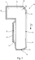
- shows the male tube fitting manufactured in accordance with the method described herein in half section;
- Fig. 2a
- shows a cross-section of a tube assembly according to a first embodiment;
- Fig. 2b
- shows a cross-section of a tube assembly according to a second embodiment;
- Fig. 3a
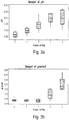
- shows a data chart illustrating the friction coefficient at the threaded section depending on a plasma setting; and
- Fig. 3b
- shows a data chart illustrating the friction coefficient at the contact section depending on the plasma setting.
- Referring to
Fig. 1 , there is shown in half section a male tube fitting 10 manufactured in accordance with the method according to the present invention. The male tube fitting 10 comprises ahead section 11 for applying a tightening torque to the male tube fitting 10, a threadedsection 12 having anexternal thread 15, acontact section 13 having acontact face 16 and a through-hole 17, which extends in an axial direction As of the male tube fitting 10. - In the method according to the invention, an
anti-corrosion layer 20 is first applied to the male tube fitting 10. Subsequently, a friction-reducinglayer 30 is applied to the male tube fitting 10 to obtain a first friction coefficient µ1. Then, the friction-reducinglayer 30 is friction modulated, at least in the threadedsection 12. Accordingly, the male tube fitting 10 comprises twolayers anti-corrosion layer 20 to protect the male tube fitting 10 from corrosion and the friction-reducinglayer 30 to reduce friction on the surface of the male tube fitting 10. However, the friction-reducinglayer 30 is not homogenous, but comprises selected places, i. e. in particular in the threadedsection 12, which have a higher friction coefficient µ2 than the friction coefficient µ1 in the remainder of the friction-reducinglayer 30. - The
anti-corrosion layer 20 can be a galvanically-applied Zn or ZnNi alloy layer, or a dip-spin-applied zinc-flake layer. Preferably, the galvanically-applied layer is a 12 % Ni alloy layer. - The friction-reducing
layer 30 comprises organic and inorganic constituents. Organic constituents are particularly waxes and polymers such as polyethylene (PE). Inorganic constituents are particularly silicates. Silicates predominantly serve for anti-corrosion protection. - Due to the friction-reducing
layer 30, the male tube fitting 10 has a first friction coefficient µ1. In particular in the threadedsection 12, a modulation of friction is applied to the friction-reducinglayer 30 by breaking up molecules in the friction-reducinglayer 30. Thereby, organic constituents in the friction-reducinglayer 30 are considerably reduced in relation to the inorganic constituents so that the threadedsection 12 has a second friction coefficient µ2. The second friction coefficient µ2 is higher than the first friction coefficient µ1. - Either a plasma treatment or, alternatively, a laser treatment can be conducted in order to break up the molecules in the in the friction-reducing
layer 30. However, the plasma treatment is more advantageous and, therefore, this invention makes use of the plasma treatment. The plasma can be generated through a high-voltage discharge or, according to the invention, with a stream or beam of oxygen ions generated by an open-air plasma system. -
Fig. 3a illustrates the effect that a particular plasma setting has on the friction coefficient µ2 at the threadedsection 12, andFig. 3b illustrates the effect that the same plasma setting has on the friction coefficient µ1 at thecontact section 13. Theplasma settings 0 to 4 shown in bothFig. 3a and 3b refer to the plasma. The higher the plasma setting, the more aggressive the plasma, i.e. particularly the higher the resulting temperature of the surface of the treated male tube fitting or tube nut. - As
Fig. 3a and 3b show, the increase of the plasma setting leads to a continuous increase of the friction coefficient µ2 at the threadedsection 12, as desired, whereas the friction coefficient µ1 at thecontact section 13 initially remains constant by approximation (plasma settings 0 to 2), and then rises when the male tube fitting 10 is overheated (plasma settings 3 to 4). - While an increase of the friction coefficient µ2 is desired, the rise of the friction coefficient µ1 through
plasma settings - The modulation of friction by open-air plasma further allows keeping the inorganic constituents, namely the silicates, intact. The additional anti-corrosion protection provided by them is still available. The inorganic constituents are also harder than the organic constituents so that also the wear properties of the friction-reducing layer are maintained.
- Before and/or during and/or after the modulation of friction an ultraviolet (UV) fluorescence value at the surface of the male tube fitting 10 is measured to determine the content of organic constituents in the
friction reducing layer 30. For example, the UV fluorescence value dropped by the modulation of friction from an average of 3309 units to 1116 units. - The thickness tA of the
anti-corrosion layer 20 of a galvanically applied Zn or Zn-AI alloy layer is partially reduced in the through-hole 17. Thereupon, the addition of a mixed organic and inorganic sealer ensures that this reduction does not affect the corrosion resistance of the male tube fitting. - Referring now to
Fig. 2a, 2b , there are shown embodiments of atube assembly 60 according to the invention with a male tube fitting 10 manufactured in accordance with the method described above. - As
Fig. 2a and 2b show, thetube assembly 60 comprises a connectingmember 50 having aninner thread 51. Furthermore, a fluid-carryingtube 40 is provided. The fluid-carryingtube 40 has anabutment face 41 formed by a flaredend 42. Flared ends 42 oftubes 40 are standardized.Fig. 2a shows a flaredend 42 having form F according to DIN 74 234:1992-09, whereasFig. 2b shows a flaredend 42 having form E. - In either of the two embodiments, the flared
end 42 is in contact with the connectingmember 50. The fluid-carryingtube 40 is received in the through-hole 17 of the male tube fitting 10 in such a way that thecontact face 16 of the male tube fitting 10 contacts theabutment face 41 of the fluid-carryingtube 40. The male tube fitting 10 with the fluid-carryingtube 40 received in the through-hole 17 is screwed into the connectingmember 50. Thus, theexternal thread 15 present in the threadedsection 12 of the male tube fitting 10 is in engagement with theinner thread 51 of the connectingmember 50. The male tube fitting 10 presses the fluid-carryingtube 40 against the connectingmember 50 so that the fluid-carryingtube 40 is axially locked. - By screwing the male tube fitting 10 into the connecting
member 50, the axial direction As of the male tube fitting 10 becomes coaxial with the axial direction Ap of thetube assembly 60. - By applying the friction-reducing
layer 30 to the male tube fitting 10, a first friction coefficient µ1 is achieved. This is advantageous, particularly in the area where thecontact face 16 of the male tube fitting 10 contacts theabutment face 41 of the fluid-carryingtube 40. When screwing the male tube fitting 10 against theabutment face 41, torsional load is applied to the fluid-carryingtube 40. In order to reduce the torsional load, the reduction of friction is particularly necessary in the area around thecontact face 16, which is done by applying the friction-reducinglayer 30. - By the friction modulation of the friction-reducing
layer 30, at least in the threadedsection 12, the organic constituents in the friction-reducinglayer 30 are reduced so that a second friction coefficient µ2 higher than the first friction coefficient µ1 is achieved. - The male tube fitting 10 and the
tube assembly 60 shown in the drawings have in common that they reduce the friction in the area of theexternal thread 15 and therefore simplify the screwing of the male tube fitting 10 into the connectingmember 50. -
- 10
- male tube fitting
- 11
- head section
- 12
- threaded section
- 13
- contact section
- 14
- screw head
- 15
- external thread
- 16
- contact face
- 17
- through-hole
- 20
- anti-corrosion layer
- 21
- runout
- 30
- friction-reducing layer
- 40
- fluid-carrying tube
- 41
- abutment face
- 42
- flared end
- 50
- connecting member
- 51
- inner thread
- 60
- tube assembly
- AP
- axial direction
- As
- axial direction
- tA
- thickness
- µ1
- first friction coefficient
- µ2
- second friction coefficient
Claims (11)
- A method of manufacturing a male tube fitting (10), comprising the following steps:a) providing a male tube fitting (10) which comprisesa head section (11) for applying a tightening torque to the male tube fitting (10),a threaded section (12) having an external thread (15),a contact section (13) configured to contact a fluid-carrying tube (40) anda through-hole (17) extending in an axial direction (As) of the male tube fitting (10);b) applying an anti-corrosion layer (20) onto the male tube fitting (10);c) applying a friction-reducing layer (30), which consists of a material having organic constituents and inorganic constituents, onto the anti-corrosion layer (20), thereby obtaining a continuous coating which has a first friction coefficient (µ1); andd) modulating the friction-reducing layer (30) at least in selected sections using a plasma treatment for breaking up molecules in the friction-reducing layer (30) to reduce the quantity of organic constituents in relation to the quantity of inorganic constituents in the friction-reducing layer (30), thereby obtaining a coating which has a second friction coefficient (µ2) higher than the first friction coefficient (µ1) in some selected places;wherein the plasma is generated with a stream of oxygen ions generated by an open-air plasma system.
- The method of claim 1, characterized by
cooling the male tube fitting (10) during the plasma treatment. - The method of claim 1 or 2, characterized by
immersing the male tube fitting (10) into a bath solution to apply the anti-corrosion layer (20) in step b). - The method of any of claims 1 to 3, characterized by
immersing the male tube fitting (10) into a bath solution to apply the friction-reducing layer (30) in step c). - The method of any of claims 1 to 4, characterized by
applying the anti-corrosion layer (20) by galvanization in step b). - The method of claim 5, characterized in that
the anti-corrosion layer (20) is a galvanically-applied Zn or ZnNi alloy layer. - The method of any of claims 1 to 6, characterized in that
the anti-corrosion layer (20) is a dip-spin-applied zinc-flake layer. - The method of any of claims 5 to 7, characterized by
passivating the anti-corrosion layer (20) after the galvanization process. - The method of any of claims 1 to 8, characterized in that
the male tube fitting (10) is made of metal, particularly of steel. - The method of any of claims 1 to 9, characterized by
measuring an ultraviolet (UV) fluorescence value at the surface of the male tube fitting (10) to determine the content of organic constituents in the friction reducing layer (30). - A tube assembly (60), particularly a brake tubing or a fuel tubing for a motor vehicle, the tube assembly (60) comprising:a fluid-carrying tube (40); anda connecting member (50) having an internal thread (51);characterized by a male tube fitting (10) as manufactured by the method of any of claims 1 to 10;wherein the internal thread (51) is configured to engage with the external thread (15) of the male tube fitting (10).
Applications Claiming Priority (2)
| Application Number | Priority Date | Filing Date | Title |
|---|---|---|---|
| PCT/EP2017/069700 WO2019024998A1 (en) | 2017-08-03 | 2017-08-03 | Method of manufacturing a male tube fitting and tube assembly comprising a male tube fitting |
| PCT/EP2018/071119 WO2019025587A1 (en) | 2017-08-03 | 2018-08-03 | Method of manufacturing a male tube fitting and tube assembly comprising a male tube fitting |
Publications (2)
| Publication Number | Publication Date |
|---|---|
| EP3555512A1 EP3555512A1 (en) | 2019-10-23 |
| EP3555512B1 true EP3555512B1 (en) | 2020-10-28 |
Family
ID=59699655
Family Applications (1)
| Application Number | Title | Priority Date | Filing Date |
|---|---|---|---|
| EP18749371.3A Active EP3555512B1 (en) | 2017-08-03 | 2018-08-03 | Method of manufacturing a male tube fitting and tube assembly comprising a male tube fitting |
Country Status (3)
| Country | Link |
|---|---|
| EP (1) | EP3555512B1 (en) |
| ES (1) | ES2834380T3 (en) |
| WO (2) | WO2019024998A1 (en) |
Cited By (2)
| Publication number | Priority date | Publication date | Assignee | Title |
|---|---|---|---|---|
| EP3884193B1 (en) * | 2019-12-27 | 2021-12-29 | Cooper-Standard Automotive (Deutschland) GmbH | Union screw for a pipeline provided with at least one flange, in particular a brake pipe |
| WO2024165301A1 (en) * | 2023-02-10 | 2024-08-15 | Ti Automotive (Heidelberg) Gmbh | Screw element with anti-corrosion coating |
Families Citing this family (1)
| Publication number | Priority date | Publication date | Assignee | Title |
|---|---|---|---|---|
| EP3961078B1 (en) * | 2020-08-27 | 2023-01-25 | TI Automotive (Heidelberg) GmbH | Method for coating a screw element, screw element and pipe connection device |
Family Cites Families (7)
| Publication number | Priority date | Publication date | Assignee | Title |
|---|---|---|---|---|
| US6130404A (en) * | 1997-03-03 | 2000-10-10 | Itt Automotive, Inc. | Electro-optical removal of plastic layer bonded to a metal tube |
| GB9816190D0 (en) * | 1998-07-25 | 1998-09-23 | Dow Corning Gmbh | Antifriction coating |
| KR101305993B1 (en) * | 2011-08-22 | 2013-09-12 | (주)백년기술 | Method for mesuring biochemical oxygen demand |
| JP5835805B2 (en) * | 2012-04-27 | 2015-12-24 | 日本製紙クレシア株式会社 | Product inspection device and inspection method thereof |
| DE102012108433C9 (en) | 2012-09-10 | 2022-11-24 | Cooper-Standard Automotive (Deutschland) Gmbh | Pipe screw for fastening a pipeline and a method for manufacturing such a pipe screw |
| DE202014102663U1 (en) | 2014-06-06 | 2014-06-24 | Ti Automotive (Heidelberg) Gmbh | Screw element for connecting pipes and pipe connection device with this screw |
| DE202017104112U1 (en) * | 2017-07-11 | 2017-07-30 | Ti Automotive (Heidelberg) Gmbh | Screw element for connection of piping and pipe connection device |
-
2017
- 2017-08-03 WO PCT/EP2017/069700 patent/WO2019024998A1/en not_active Ceased
-
2018
- 2018-08-03 ES ES18749371T patent/ES2834380T3/en active Active
- 2018-08-03 WO PCT/EP2018/071119 patent/WO2019025587A1/en not_active Ceased
- 2018-08-03 EP EP18749371.3A patent/EP3555512B1/en active Active
Non-Patent Citations (1)
| Title |
|---|
| None * |
Cited By (2)
| Publication number | Priority date | Publication date | Assignee | Title |
|---|---|---|---|---|
| EP3884193B1 (en) * | 2019-12-27 | 2021-12-29 | Cooper-Standard Automotive (Deutschland) GmbH | Union screw for a pipeline provided with at least one flange, in particular a brake pipe |
| WO2024165301A1 (en) * | 2023-02-10 | 2024-08-15 | Ti Automotive (Heidelberg) Gmbh | Screw element with anti-corrosion coating |
Also Published As
| Publication number | Publication date |
|---|---|
| ES2834380T3 (en) | 2021-06-17 |
| EP3555512A1 (en) | 2019-10-23 |
| WO2019025587A1 (en) | 2019-02-07 |
| WO2019024998A1 (en) | 2019-02-07 |
Similar Documents
| Publication | Publication Date | Title |
|---|---|---|
| EP3555512B1 (en) | Method of manufacturing a male tube fitting and tube assembly comprising a male tube fitting | |
| RU2647282C1 (en) | Threaded connection for pipes of oil-field grade and composition for photo-cured coating | |
| US10125905B2 (en) | Screw element for the connection of tubes and tube connection device having this screw element | |
| EA023140B1 (en) | Tubular threaded joint having improved low temperature performance | |
| US9400068B2 (en) | Crimp-on pipe connection accessory | |
| CN102947489A (en) | Anti-corrosion agent, covered wire with terminal, and wiring harness | |
| EP2706277B1 (en) | Tubular screw for fixing a pipe and a method for producing such a tubular screw | |
| EP3652475B1 (en) | A pipe connecting device with screw element for connecting pipes | |
| US20100028101A1 (en) | Hot pressing process, particularly for providing metal unions for pneumatic, hydraulic and fluid-operated circuits, and metal union obtained thereby | |
| JP6206240B2 (en) | Coated electric wire with terminal, manufacturing method thereof, and wire harness | |
| US20080025810A1 (en) | Wire Threaded Insert Made of Magnesium or Aluminium Alloy | |
| JP6111997B2 (en) | Anticorrosive, coated electric wire with terminal and wire harness | |
| US20050153597A1 (en) | Electrical capped contact stud and method of fastening an electrical contact | |
| US7788802B2 (en) | Method of fastening an electrical contact | |
| FR2786204A1 (en) | Method for soldering metallic construction parts equipped with corrosion protection layers containing semiconductor material as filler which is excited into its conducting state during soldering | |
| JP2010165588A (en) | Protection structure of connector | |
| EP2798052A1 (en) | Threaded tubular component and method for coating such a threaded tubular component | |
| US12606144B2 (en) | Union screw for a pipeline provided with at least one flange, in particular a brake pipe | |
| JP7026290B2 (en) | Inserts for connecting electrical connections to the wall and protective caps for inserts | |
| BE1005573A3 (en) | Improvements to heat exchange in copper boiler wall. | |
| KR100897112B1 (en) | Car brake bracket structure | |
| EP3325828B1 (en) | Bolt with restrained unscrewing | |
| FR3161013A1 (en) | Pressurized gas tank including a protective coating | |
| BE1014113A3 (en) | STEEL WIRE WITH FLUORESCENT UV lacquer coating. | |
| EP3977354A1 (en) | Identification device, corresponding tubular element and method |
Legal Events
| Date | Code | Title | Description |
|---|---|---|---|
| STAA | Information on the status of an ep patent application or granted ep patent |
Free format text: STATUS: UNKNOWN |
|
| STAA | Information on the status of an ep patent application or granted ep patent |
Free format text: STATUS: THE INTERNATIONAL PUBLICATION HAS BEEN MADE |
|
| PUAI | Public reference made under article 153(3) epc to a published international application that has entered the european phase |
Free format text: ORIGINAL CODE: 0009012 |
|
| STAA | Information on the status of an ep patent application or granted ep patent |
Free format text: STATUS: REQUEST FOR EXAMINATION WAS MADE |
|
| 17P | Request for examination filed |
Effective date: 20190715 |
|
| AK | Designated contracting states |
Kind code of ref document: A1 Designated state(s): AL AT BE BG CH CY CZ DE DK EE ES FI FR GB GR HR HU IE IS IT LI LT LU LV MC MK MT NL NO PL PT RO RS SE SI SK SM TR |
|
| AX | Request for extension of the european patent |
Extension state: BA ME |
|
| STAA | Information on the status of an ep patent application or granted ep patent |
Free format text: STATUS: EXAMINATION IS IN PROGRESS |
|
| 17Q | First examination report despatched |
Effective date: 20200204 |
|
| GRAP | Despatch of communication of intention to grant a patent |
Free format text: ORIGINAL CODE: EPIDOSNIGR1 |
|
| STAA | Information on the status of an ep patent application or granted ep patent |
Free format text: STATUS: GRANT OF PATENT IS INTENDED |
|
| DAV | Request for validation of the european patent (deleted) | ||
| DAX | Request for extension of the european patent (deleted) | ||
| INTG | Intention to grant announced |
Effective date: 20200817 |
|
| GRAS | Grant fee paid |
Free format text: ORIGINAL CODE: EPIDOSNIGR3 |
|
| GRAA | (expected) grant |
Free format text: ORIGINAL CODE: 0009210 |
|
| STAA | Information on the status of an ep patent application or granted ep patent |
Free format text: STATUS: THE PATENT HAS BEEN GRANTED |
|
| AK | Designated contracting states |
Kind code of ref document: B1 Designated state(s): AL AT BE BG CH CY CZ DE DK EE ES FI FR GB GR HR HU IE IS IT LI LT LU LV MC MK MT NL NO PL PT RO RS SE SI SK SM TR |
|
| REG | Reference to a national code |
Ref country code: GB Ref legal event code: FG4D |
|
| REG | Reference to a national code |
Ref country code: CH Ref legal event code: EP |
|
| REG | Reference to a national code |
Ref country code: AT Ref legal event code: REF Ref document number: 1328572 Country of ref document: AT Kind code of ref document: T Effective date: 20201115 |
|
| REG | Reference to a national code |
Ref country code: DE Ref legal event code: R096 Ref document number: 602018009194 Country of ref document: DE |
|
| REG | Reference to a national code |
Ref country code: IE Ref legal event code: FG4D |
|
| REG | Reference to a national code |
Ref country code: AT Ref legal event code: MK05 Ref document number: 1328572 Country of ref document: AT Kind code of ref document: T Effective date: 20201028 |
|
| REG | Reference to a national code |
Ref country code: NL Ref legal event code: MP Effective date: 20201028 |
|
| PG25 | Lapsed in a contracting state [announced via postgrant information from national office to epo] |
Ref country code: PT Free format text: LAPSE BECAUSE OF FAILURE TO SUBMIT A TRANSLATION OF THE DESCRIPTION OR TO PAY THE FEE WITHIN THE PRESCRIBED TIME-LIMIT Effective date: 20210301 Ref country code: RS Free format text: LAPSE BECAUSE OF FAILURE TO SUBMIT A TRANSLATION OF THE DESCRIPTION OR TO PAY THE FEE WITHIN THE PRESCRIBED TIME-LIMIT Effective date: 20201028 Ref country code: FI Free format text: LAPSE BECAUSE OF FAILURE TO SUBMIT A TRANSLATION OF THE DESCRIPTION OR TO PAY THE FEE WITHIN THE PRESCRIBED TIME-LIMIT Effective date: 20201028 Ref country code: NO Free format text: LAPSE BECAUSE OF FAILURE TO SUBMIT A TRANSLATION OF THE DESCRIPTION OR TO PAY THE FEE WITHIN THE PRESCRIBED TIME-LIMIT Effective date: 20210128 Ref country code: GR Free format text: LAPSE BECAUSE OF FAILURE TO SUBMIT A TRANSLATION OF THE DESCRIPTION OR TO PAY THE FEE WITHIN THE PRESCRIBED TIME-LIMIT Effective date: 20210129 |
|
| REG | Reference to a national code |
Ref country code: LT Ref legal event code: MG4D |
|
| PG25 | Lapsed in a contracting state [announced via postgrant information from national office to epo] |
Ref country code: AT Free format text: LAPSE BECAUSE OF FAILURE TO SUBMIT A TRANSLATION OF THE DESCRIPTION OR TO PAY THE FEE WITHIN THE PRESCRIBED TIME-LIMIT Effective date: 20201028 Ref country code: BG Free format text: LAPSE BECAUSE OF FAILURE TO SUBMIT A TRANSLATION OF THE DESCRIPTION OR TO PAY THE FEE WITHIN THE PRESCRIBED TIME-LIMIT Effective date: 20210128 Ref country code: SE Free format text: LAPSE BECAUSE OF FAILURE TO SUBMIT A TRANSLATION OF THE DESCRIPTION OR TO PAY THE FEE WITHIN THE PRESCRIBED TIME-LIMIT Effective date: 20201028 Ref country code: IS Free format text: LAPSE BECAUSE OF FAILURE TO SUBMIT A TRANSLATION OF THE DESCRIPTION OR TO PAY THE FEE WITHIN THE PRESCRIBED TIME-LIMIT Effective date: 20210228 Ref country code: PL Free format text: LAPSE BECAUSE OF FAILURE TO SUBMIT A TRANSLATION OF THE DESCRIPTION OR TO PAY THE FEE WITHIN THE PRESCRIBED TIME-LIMIT Effective date: 20201028 Ref country code: LV Free format text: LAPSE BECAUSE OF FAILURE TO SUBMIT A TRANSLATION OF THE DESCRIPTION OR TO PAY THE FEE WITHIN THE PRESCRIBED TIME-LIMIT Effective date: 20201028 |
|
| REG | Reference to a national code |
Ref country code: ES Ref legal event code: FG2A Ref document number: 2834380 Country of ref document: ES Kind code of ref document: T3 Effective date: 20210617 |
|
| PG25 | Lapsed in a contracting state [announced via postgrant information from national office to epo] |
Ref country code: NL Free format text: LAPSE BECAUSE OF FAILURE TO SUBMIT A TRANSLATION OF THE DESCRIPTION OR TO PAY THE FEE WITHIN THE PRESCRIBED TIME-LIMIT Effective date: 20201028 Ref country code: HR Free format text: LAPSE BECAUSE OF FAILURE TO SUBMIT A TRANSLATION OF THE DESCRIPTION OR TO PAY THE FEE WITHIN THE PRESCRIBED TIME-LIMIT Effective date: 20201028 |
|
| REG | Reference to a national code |
Ref country code: DE Ref legal event code: R097 Ref document number: 602018009194 Country of ref document: DE |
|
| PG25 | Lapsed in a contracting state [announced via postgrant information from national office to epo] |
Ref country code: EE Free format text: LAPSE BECAUSE OF FAILURE TO SUBMIT A TRANSLATION OF THE DESCRIPTION OR TO PAY THE FEE WITHIN THE PRESCRIBED TIME-LIMIT Effective date: 20201028 Ref country code: CZ Free format text: LAPSE BECAUSE OF FAILURE TO SUBMIT A TRANSLATION OF THE DESCRIPTION OR TO PAY THE FEE WITHIN THE PRESCRIBED TIME-LIMIT Effective date: 20201028 Ref country code: SK Free format text: LAPSE BECAUSE OF FAILURE TO SUBMIT A TRANSLATION OF THE DESCRIPTION OR TO PAY THE FEE WITHIN THE PRESCRIBED TIME-LIMIT Effective date: 20201028 Ref country code: SM Free format text: LAPSE BECAUSE OF FAILURE TO SUBMIT A TRANSLATION OF THE DESCRIPTION OR TO PAY THE FEE WITHIN THE PRESCRIBED TIME-LIMIT Effective date: 20201028 Ref country code: LT Free format text: LAPSE BECAUSE OF FAILURE TO SUBMIT A TRANSLATION OF THE DESCRIPTION OR TO PAY THE FEE WITHIN THE PRESCRIBED TIME-LIMIT Effective date: 20201028 Ref country code: RO Free format text: LAPSE BECAUSE OF FAILURE TO SUBMIT A TRANSLATION OF THE DESCRIPTION OR TO PAY THE FEE WITHIN THE PRESCRIBED TIME-LIMIT Effective date: 20201028 |
|
| PG25 | Lapsed in a contracting state [announced via postgrant information from national office to epo] |
Ref country code: DK Free format text: LAPSE BECAUSE OF FAILURE TO SUBMIT A TRANSLATION OF THE DESCRIPTION OR TO PAY THE FEE WITHIN THE PRESCRIBED TIME-LIMIT Effective date: 20201028 |
|
| PLBE | No opposition filed within time limit |
Free format text: ORIGINAL CODE: 0009261 |
|
| STAA | Information on the status of an ep patent application or granted ep patent |
Free format text: STATUS: NO OPPOSITION FILED WITHIN TIME LIMIT |
|
| 26N | No opposition filed |
Effective date: 20210729 |
|
| PG25 | Lapsed in a contracting state [announced via postgrant information from national office to epo] |
Ref country code: AL Free format text: LAPSE BECAUSE OF FAILURE TO SUBMIT A TRANSLATION OF THE DESCRIPTION OR TO PAY THE FEE WITHIN THE PRESCRIBED TIME-LIMIT Effective date: 20201028 |
|
| PG25 | Lapsed in a contracting state [announced via postgrant information from national office to epo] |
Ref country code: SI Free format text: LAPSE BECAUSE OF FAILURE TO SUBMIT A TRANSLATION OF THE DESCRIPTION OR TO PAY THE FEE WITHIN THE PRESCRIBED TIME-LIMIT Effective date: 20201028 |
|
| REG | Reference to a national code |
Ref country code: CH Ref legal event code: PL |
|
| PG25 | Lapsed in a contracting state [announced via postgrant information from national office to epo] |
Ref country code: MC Free format text: LAPSE BECAUSE OF FAILURE TO SUBMIT A TRANSLATION OF THE DESCRIPTION OR TO PAY THE FEE WITHIN THE PRESCRIBED TIME-LIMIT Effective date: 20201028 |
|
| REG | Reference to a national code |
Ref country code: BE Ref legal event code: MM Effective date: 20210831 |
|
| PG25 | Lapsed in a contracting state [announced via postgrant information from national office to epo] |
Ref country code: LI Free format text: LAPSE BECAUSE OF NON-PAYMENT OF DUE FEES Effective date: 20210831 Ref country code: CH Free format text: LAPSE BECAUSE OF NON-PAYMENT OF DUE FEES Effective date: 20210831 |
|
| PG25 | Lapsed in a contracting state [announced via postgrant information from national office to epo] |
Ref country code: IS Free format text: LAPSE BECAUSE OF FAILURE TO SUBMIT A TRANSLATION OF THE DESCRIPTION OR TO PAY THE FEE WITHIN THE PRESCRIBED TIME-LIMIT Effective date: 20210228 Ref country code: LU Free format text: LAPSE BECAUSE OF NON-PAYMENT OF DUE FEES Effective date: 20210803 |
|
| PG25 | Lapsed in a contracting state [announced via postgrant information from national office to epo] |
Ref country code: IE Free format text: LAPSE BECAUSE OF NON-PAYMENT OF DUE FEES Effective date: 20210803 Ref country code: BE Free format text: LAPSE BECAUSE OF NON-PAYMENT OF DUE FEES Effective date: 20210831 |
|
| PG25 | Lapsed in a contracting state [announced via postgrant information from national office to epo] |
Ref country code: CY Free format text: LAPSE BECAUSE OF FAILURE TO SUBMIT A TRANSLATION OF THE DESCRIPTION OR TO PAY THE FEE WITHIN THE PRESCRIBED TIME-LIMIT Effective date: 20201028 |
|
| PG25 | Lapsed in a contracting state [announced via postgrant information from national office to epo] |
Ref country code: HU Free format text: LAPSE BECAUSE OF FAILURE TO SUBMIT A TRANSLATION OF THE DESCRIPTION OR TO PAY THE FEE WITHIN THE PRESCRIBED TIME-LIMIT; INVALID AB INITIO Effective date: 20180803 |
|
| PG25 | Lapsed in a contracting state [announced via postgrant information from national office to epo] |
Ref country code: MK Free format text: LAPSE BECAUSE OF FAILURE TO SUBMIT A TRANSLATION OF THE DESCRIPTION OR TO PAY THE FEE WITHIN THE PRESCRIBED TIME-LIMIT Effective date: 20201028 |
|
| PG25 | Lapsed in a contracting state [announced via postgrant information from national office to epo] |
Ref country code: TR Free format text: LAPSE BECAUSE OF FAILURE TO SUBMIT A TRANSLATION OF THE DESCRIPTION OR TO PAY THE FEE WITHIN THE PRESCRIBED TIME-LIMIT Effective date: 20201028 |
|
| PG25 | Lapsed in a contracting state [announced via postgrant information from national office to epo] |
Ref country code: MT Free format text: LAPSE BECAUSE OF FAILURE TO SUBMIT A TRANSLATION OF THE DESCRIPTION OR TO PAY THE FEE WITHIN THE PRESCRIBED TIME-LIMIT Effective date: 20201028 |
|
| PGFP | Annual fee paid to national office [announced via postgrant information from national office to epo] |
Ref country code: ES Payment date: 20250917 Year of fee payment: 8 |
|
| PGFP | Annual fee paid to national office [announced via postgrant information from national office to epo] |
Ref country code: DE Payment date: 20250910 Year of fee payment: 8 |
|
| PGFP | Annual fee paid to national office [announced via postgrant information from national office to epo] |
Ref country code: IT Payment date: 20250829 Year of fee payment: 8 |
|
| PGFP | Annual fee paid to national office [announced via postgrant information from national office to epo] |
Ref country code: GB Payment date: 20250818 Year of fee payment: 8 |
|
| PGFP | Annual fee paid to national office [announced via postgrant information from national office to epo] |
Ref country code: FR Payment date: 20250821 Year of fee payment: 8 |