EP3555464B1 - Rotor arresting device for a wind turbine and method - Google Patents
Rotor arresting device for a wind turbine and method Download PDFInfo
- Publication number
- EP3555464B1 EP3555464B1 EP17816522.1A EP17816522A EP3555464B1 EP 3555464 B1 EP3555464 B1 EP 3555464B1 EP 17816522 A EP17816522 A EP 17816522A EP 3555464 B1 EP3555464 B1 EP 3555464B1
- Authority
- EP
- European Patent Office
- Prior art keywords
- arresting
- tooth
- rotor
- locking
- arresting element
- Prior art date
- Legal status (The legal status is an assumption and is not a legal conclusion. Google has not performed a legal analysis and makes no representation as to the accuracy of the status listed.)
- Active
Links
- 238000000034 method Methods 0.000 title claims description 15
- 230000033001 locomotion Effects 0.000 claims description 35
- 238000010008 shearing Methods 0.000 claims description 6
- 230000005540 biological transmission Effects 0.000 claims description 5
- 230000007423 decrease Effects 0.000 claims description 4
- 230000003068 static effect Effects 0.000 claims 3
- 238000009434 installation Methods 0.000 description 20
- 238000011161 development Methods 0.000 description 8
- 230000018109 developmental process Effects 0.000 description 8
- 238000013461 design Methods 0.000 description 6
- 238000012423 maintenance Methods 0.000 description 4
- 230000008439 repair process Effects 0.000 description 3
- 240000005561 Musa balbisiana Species 0.000 description 1
- 235000018290 Musa x paradisiaca Nutrition 0.000 description 1
- 208000012886 Vertigo Diseases 0.000 description 1
- 230000009286 beneficial effect Effects 0.000 description 1
- 230000003247 decreasing effect Effects 0.000 description 1
- 230000001419 dependent effect Effects 0.000 description 1
- 230000000694 effects Effects 0.000 description 1
- 230000005520 electrodynamics Effects 0.000 description 1
- 238000003780 insertion Methods 0.000 description 1
- 230000037431 insertion Effects 0.000 description 1
- 108090000623 proteins and genes Proteins 0.000 description 1
Images


Classifications
-
- F—MECHANICAL ENGINEERING; LIGHTING; HEATING; WEAPONS; BLASTING
- F03—MACHINES OR ENGINES FOR LIQUIDS; WIND, SPRING, OR WEIGHT MOTORS; PRODUCING MECHANICAL POWER OR A REACTIVE PROPULSIVE THRUST, NOT OTHERWISE PROVIDED FOR
- F03D—WIND MOTORS
- F03D7/00—Controlling wind motors
- F03D7/02—Controlling wind motors the wind motors having rotation axis substantially parallel to the air flow entering the rotor
- F03D7/0264—Controlling wind motors the wind motors having rotation axis substantially parallel to the air flow entering the rotor for stopping; controlling in emergency situations
- F03D7/0268—Parking or storm protection
-
- F—MECHANICAL ENGINEERING; LIGHTING; HEATING; WEAPONS; BLASTING
- F03—MACHINES OR ENGINES FOR LIQUIDS; WIND, SPRING, OR WEIGHT MOTORS; PRODUCING MECHANICAL POWER OR A REACTIVE PROPULSIVE THRUST, NOT OTHERWISE PROVIDED FOR
- F03D—WIND MOTORS
- F03D7/00—Controlling wind motors
- F03D7/02—Controlling wind motors the wind motors having rotation axis substantially parallel to the air flow entering the rotor
- F03D7/0264—Controlling wind motors the wind motors having rotation axis substantially parallel to the air flow entering the rotor for stopping; controlling in emergency situations
-
- F—MECHANICAL ENGINEERING; LIGHTING; HEATING; WEAPONS; BLASTING
- F03—MACHINES OR ENGINES FOR LIQUIDS; WIND, SPRING, OR WEIGHT MOTORS; PRODUCING MECHANICAL POWER OR A REACTIVE PROPULSIVE THRUST, NOT OTHERWISE PROVIDED FOR
- F03D—WIND MOTORS
- F03D13/00—Assembly, mounting or commissioning of wind motors; Arrangements specially adapted for transporting wind motor components
- F03D13/10—Assembly of wind motors; Arrangements for erecting wind motors
-
- F—MECHANICAL ENGINEERING; LIGHTING; HEATING; WEAPONS; BLASTING
- F03—MACHINES OR ENGINES FOR LIQUIDS; WIND, SPRING, OR WEIGHT MOTORS; PRODUCING MECHANICAL POWER OR A REACTIVE PROPULSIVE THRUST, NOT OTHERWISE PROVIDED FOR
- F03D—WIND MOTORS
- F03D80/00—Details, components or accessories not provided for in groups F03D1/00 - F03D17/00
- F03D80/50—Maintenance or repair
-
- F—MECHANICAL ENGINEERING; LIGHTING; HEATING; WEAPONS; BLASTING
- F03—MACHINES OR ENGINES FOR LIQUIDS; WIND, SPRING, OR WEIGHT MOTORS; PRODUCING MECHANICAL POWER OR A REACTIVE PROPULSIVE THRUST, NOT OTHERWISE PROVIDED FOR
- F03D—WIND MOTORS
- F03D13/00—Assembly, mounting or commissioning of wind motors; Arrangements specially adapted for transporting wind motor components
-
- F—MECHANICAL ENGINEERING; LIGHTING; HEATING; WEAPONS; BLASTING
- F03—MACHINES OR ENGINES FOR LIQUIDS; WIND, SPRING, OR WEIGHT MOTORS; PRODUCING MECHANICAL POWER OR A REACTIVE PROPULSIVE THRUST, NOT OTHERWISE PROVIDED FOR
- F03D—WIND MOTORS
- F03D80/00—Details, components or accessories not provided for in groups F03D1/00 - F03D17/00
-
- F—MECHANICAL ENGINEERING; LIGHTING; HEATING; WEAPONS; BLASTING
- F05—INDEXING SCHEMES RELATING TO ENGINES OR PUMPS IN VARIOUS SUBCLASSES OF CLASSES F01-F04
- F05B—INDEXING SCHEME RELATING TO WIND, SPRING, WEIGHT, INERTIA OR LIKE MOTORS, TO MACHINES OR ENGINES FOR LIQUIDS COVERED BY SUBCLASSES F03B, F03D AND F03G
- F05B2230/00—Manufacture
- F05B2230/60—Assembly methods
- F05B2230/604—Assembly methods using positioning or alignment devices for aligning or centering, e.g. pins
- F05B2230/608—Assembly methods using positioning or alignment devices for aligning or centering, e.g. pins for adjusting the position or the alignment, e.g. wedges or excenters
-
- F—MECHANICAL ENGINEERING; LIGHTING; HEATING; WEAPONS; BLASTING
- F05—INDEXING SCHEMES RELATING TO ENGINES OR PUMPS IN VARIOUS SUBCLASSES OF CLASSES F01-F04
- F05B—INDEXING SCHEME RELATING TO WIND, SPRING, WEIGHT, INERTIA OR LIKE MOTORS, TO MACHINES OR ENGINES FOR LIQUIDS COVERED BY SUBCLASSES F03B, F03D AND F03G
- F05B2230/00—Manufacture
- F05B2230/70—Disassembly methods
-
- F—MECHANICAL ENGINEERING; LIGHTING; HEATING; WEAPONS; BLASTING
- F05—INDEXING SCHEMES RELATING TO ENGINES OR PUMPS IN VARIOUS SUBCLASSES OF CLASSES F01-F04
- F05B—INDEXING SCHEME RELATING TO WIND, SPRING, WEIGHT, INERTIA OR LIKE MOTORS, TO MACHINES OR ENGINES FOR LIQUIDS COVERED BY SUBCLASSES F03B, F03D AND F03G
- F05B2230/00—Manufacture
- F05B2230/80—Repairing, retrofitting or upgrading methods
-
- F—MECHANICAL ENGINEERING; LIGHTING; HEATING; WEAPONS; BLASTING
- F05—INDEXING SCHEMES RELATING TO ENGINES OR PUMPS IN VARIOUS SUBCLASSES OF CLASSES F01-F04
- F05B—INDEXING SCHEME RELATING TO WIND, SPRING, WEIGHT, INERTIA OR LIKE MOTORS, TO MACHINES OR ENGINES FOR LIQUIDS COVERED BY SUBCLASSES F03B, F03D AND F03G
- F05B2260/00—Function
- F05B2260/30—Retaining components in desired mutual position
- F05B2260/31—Locking rotor in position
-
- F—MECHANICAL ENGINEERING; LIGHTING; HEATING; WEAPONS; BLASTING
- F05—INDEXING SCHEMES RELATING TO ENGINES OR PUMPS IN VARIOUS SUBCLASSES OF CLASSES F01-F04
- F05B—INDEXING SCHEME RELATING TO WIND, SPRING, WEIGHT, INERTIA OR LIKE MOTORS, TO MACHINES OR ENGINES FOR LIQUIDS COVERED BY SUBCLASSES F03B, F03D AND F03G
- F05B2270/00—Control
- F05B2270/30—Control parameters, e.g. input parameters
- F05B2270/326—Rotor angle
-
- Y—GENERAL TAGGING OF NEW TECHNOLOGICAL DEVELOPMENTS; GENERAL TAGGING OF CROSS-SECTIONAL TECHNOLOGIES SPANNING OVER SEVERAL SECTIONS OF THE IPC; TECHNICAL SUBJECTS COVERED BY FORMER USPC CROSS-REFERENCE ART COLLECTIONS [XRACs] AND DIGESTS
- Y02—TECHNOLOGIES OR APPLICATIONS FOR MITIGATION OR ADAPTATION AGAINST CLIMATE CHANGE
- Y02B—CLIMATE CHANGE MITIGATION TECHNOLOGIES RELATED TO BUILDINGS, e.g. HOUSING, HOUSE APPLIANCES OR RELATED END-USER APPLICATIONS
- Y02B10/00—Integration of renewable energy sources in buildings
- Y02B10/30—Wind power
-
- Y—GENERAL TAGGING OF NEW TECHNOLOGICAL DEVELOPMENTS; GENERAL TAGGING OF CROSS-SECTIONAL TECHNOLOGIES SPANNING OVER SEVERAL SECTIONS OF THE IPC; TECHNICAL SUBJECTS COVERED BY FORMER USPC CROSS-REFERENCE ART COLLECTIONS [XRACs] AND DIGESTS
- Y02—TECHNOLOGIES OR APPLICATIONS FOR MITIGATION OR ADAPTATION AGAINST CLIMATE CHANGE
- Y02E—REDUCTION OF GREENHOUSE GAS [GHG] EMISSIONS, RELATED TO ENERGY GENERATION, TRANSMISSION OR DISTRIBUTION
- Y02E10/00—Energy generation through renewable energy sources
- Y02E10/70—Wind energy
- Y02E10/72—Wind turbines with rotation axis in wind direction
-
- Y—GENERAL TAGGING OF NEW TECHNOLOGICAL DEVELOPMENTS; GENERAL TAGGING OF CROSS-SECTIONAL TECHNOLOGIES SPANNING OVER SEVERAL SECTIONS OF THE IPC; TECHNICAL SUBJECTS COVERED BY FORMER USPC CROSS-REFERENCE ART COLLECTIONS [XRACs] AND DIGESTS
- Y02—TECHNOLOGIES OR APPLICATIONS FOR MITIGATION OR ADAPTATION AGAINST CLIMATE CHANGE
- Y02P—CLIMATE CHANGE MITIGATION TECHNOLOGIES IN THE PRODUCTION OR PROCESSING OF GOODS
- Y02P70/00—Climate change mitigation technologies in the production process for final industrial or consumer products
- Y02P70/50—Manufacturing or production processes characterised by the final manufactured product
Definitions
- the invention relates to a rotor locking device for a wind power plant, a wind power plant and a method for locking and / or rotating a rotor of a wind power plant.
- a wind turbine converts the energy of the wind into electrical energy.
- the dominant design of wind turbines is the three-bladed horizontal axis wind turbine, in which the rotor is on the windward side during operation and the machine house is arranged on a tower and the wind direction is actively tracked.
- the aerodynamic rotor of the wind energy installation preferably comprises one, two or more rotor blades, which are preferably attached to a common hub.
- This hub is also preferably connected in a torsionally rigid manner to a rotary assembly.
- the rotor drives a generator rotor, for example via the hub and an axle journal.
- the rotary assembly also generally includes a rotor shaft which connects the rotor and a gearbox to one another.
- the gearbox converts the rotary movement of the rotor into a gearbox output movement so that this gearbox output movement can then be transmitted to a generator.
- the rotor is understood to be the aerodynamic rotor of a wind energy installation with, as a rule, three rotor blades.
- a generator rotor is understood to be an electrodynamic rotor of a generator, preferably of a generator for a wind energy installation.
- a generator within the meaning of this application includes both internal rotor generators, in which a generator rotor rotates radially inside a stator, and external rotor generators, in which a generator rotor rotates radially outside around a stator.
- the aerodynamic rotor of a wind turbine is to be locked in various situations, it being further preferred that the rotor is locked in a specific rotational position.
- the rotor may be locked in order to carry out repair and / or maintenance work, for example inside the nacelle or in the area of the hub. It may also be necessary to lock the rotor as soon as the wind energy installation is assembled and / or disassembled. For example, high locking forces and / or locking torques arise for holding a rotor in a defined position if not all the rotor blades provided are arranged and the rotor is thus in an unstable position.
- Rotor locking devices known in the prior art have the particular aim of providing secure locking. This is explained in particular by the fact that appropriate safety precautions for those working on the wind energy installation Individuals should be taken care of. Therefore, in the case of rotor locking devices known in the prior art, primarily combinations of bolts and preferably several openings are provided. Furthermore, openings are preferably arranged on a generator rotor of a generator, in particular on a rotor carrier, the direction of passage of which is preferably arranged essentially parallel to an axis of rotation of the generator. On the generator stator, in particular on a stator carrier, bolts that correspond to the openings are preferably arranged, which bolts can be arranged in the openings. By arranging the bolts within the openings, a locking of the generator rotor and thus also of the aerodynamic rotor can be achieved.
- a rotor locking device mentioned and described above can, on the one hand, provide a secure locking of the rotor, but positioning of the rotor is only possible in the positions at which openings are provided on the rotary assembly. Furthermore, for example, to assemble rotor blades, it is necessary to release the lock after assembling a first rotor blade in order to turn the rotor into the position for assembling the second rotor blade, preferably in a six o'clock position, and to lock it there again . This results in high costs and great effort in a wide variety of application areas. While the existing systems and methods for locking wind turbine rotors offer various advantages, further improvements are desirable.
- German Patent and Trademark Office researched the following prior art in the priority application for the present application: DE 100 31 472 C1 , DE 10 2008 063 043 B4 , DE 10 2008 054 100 A1 and DE 21 2013 000 242 U1 .
- Another prior art document is EP 2 927 479 A1 .
- a rotor locking device for a wind energy installation with a A rotor, a rotationally rigidly connected to the rotor rotation assembly and a stationary assembly relative to the rotation assembly, comprising a toothed disk that can be arranged on the rotation assembly, with a plurality of locking recesses arranged along a circumference, two adjacent locking recesses forming a tooth, a first locking module with at least one first Locking element, a second locking module with at least one second locking element, wherein the first locking module and the second locking module can be arranged on the stand assembly, wherein the first locking element and the second locking element are arranged and designed to engage in locking recesses of the toothed disk, wherein the toothed disk is in the circumferential direction of the
- the distance between the at least one first locking element and the at least one second locking element is a non-integer multiple of a tooth tip distance of the toothed disk.
- the rotary assembly is torsionally rigidly connected to the rotor.
- a rotor is understood to mean the assembly comprising at least one rotor blade, a hub on which the at least one rotor blade is arranged. Often the rotor also has a spinner.
- the rotary assembly can comprise, for example, a rotor carrier and / or an axle journal and / or a rotor shaft which is connected to the rotor hub in a torsionally rigid manner.
- the rotary assembly can preferably also comprise a generator rotor.
- the rotary assembly preferably comprises any component that is also set into rotary motion by means of a rotation of the rotor.
- a wind power installation includes a standing assembly which is stationary with respect to the rotating assembly.
- the stand assembly comprises in particular elements of this type which are arranged within the nacelle and which do not perform any rotational movement about an axis of rotation of the rotor.
- the stand assembly is therefore stationary with respect to the rotation assembly.
- the stand assembly together with the nacelle can usually be rotated around an essentially vertical axis, since wind turbines generally have a wind direction tracking system, so that the nacelle rotate around an axis parallel to the longitudinal axis of the tower can.
- the stand assembly which is arranged inside the nacelle, thus also rotates with respect to a point outside the nacelle, in particular with respect to the ground on which the wind power installation is erected.
- stationary is to be understood in relation to the rotating rotary assembly.
- the stand assembly includes for example a generator stator, a journal, a machine carrier, a generator housing or a gear housing.
- the stand assembly preferably comprises an element on which the locking modules can be arranged.
- the toothed disk that can be arranged on the rotary assembly has a plurality of locking recesses along a circumference.
- the toothed washer can either be an element which is provided specifically for the rotor locking and which is arranged in a torsionally rigid manner on the rotary assembly, or alternatively the toothed washer can also be arranged on a known element of the rotary assembly.
- the toothed disk can be part of a generator rotor disk in that the generator rotor disk has locking recesses arranged along a circumference.
- a tooth system is formed by the plurality of locking recesses along the circumference of the toothed disk.
- the toothing can, for example, have a wave profile, which is characterized in that the recesses and / or the teeth have a partially circular, in particular semicircular, geometry. Furthermore, the toothing can preferably have an involute and / or cycloid toothing. In addition, a saw tooth system can be provided.
- the locking recesses or the teeth formed by the locking recesses must have such a geometry that the at least one first locking element and the at least one second locking element can always be arranged in one of the locking recesses, despite the spacing of these two locking elements according to the invention.
- the locking elements or the locking recesses are to be designed in such a way that when a locking element is moved into a locking recess, a shearing movement may take place so that moving the toothed washer enables a locking element or a section of a locking element to be arranged in a locking recess.
- the at least one first locking element is arranged on the first locking module.
- the first locking element preferably extends from a module end to an engagement end. With the module end, the first locking element is preferably arranged on and / or in the first locking module.
- the first locking element is preferably arranged on the first locking module in such a way that the first locking element can be moved relative to the locking module.
- the engagement end of the first locking element is preferably facing away from the locking module and, in the operating state, facing the toothed disk.
- a region adjoining the engagement end preferably has a geometry which at least partially represents a negative geometry of the locking recesses.
- an area adjacent to the engagement end is designed in such a way that when a locking element is inserted into a locking recess that does not take place exactly in the center, a shear movement and thus also a shear force, in particular in the tangential direction of the toothed disk, arise.
- a shear movement and thus also a shear force in particular in the tangential direction of the toothed disk, arise.
- this arrangement of the first locking element results in the fact that a shear force is exerted on the assembly connected to the toothed washer and rotation of this assembly relative to the first locking element can be made possible.
- a rotation of the rotation assembly or the rotor can thus be made possible.
- the first locking module and the second locking module can be arranged on a stand assembly of a wind turbine.
- the first locking module and the second locking module are preferably and essentially not movable in the direction of rotation of the rotating assembly.
- the at least one first locking element and / or the at least one second locking element is / are also arranged fixedly with respect to a direction of rotation of the rotary assembly.
- this fixed arrangement of the at least one first locking element and / or the at least one second locking element on the first locking module or the second locking module is designed such that they can engage in locking recesses of the toothed disk.
- the locking elements on the locking modules are preferably arranged to be movable in the direction of the toothed disk.
- the locking elements are fixedly arranged on the locking modules, but the locking modules with the locking elements fixedly arranged on them are designed to be movable in the direction of the toothed disk.
- An engagement of a locking element in a locking recess is to be understood in particular to mean that the locking element is arranged in the locking recess of the toothed disk in such a way that the toothed disk can neither be moved in a first direction of rotation nor in a second direction of rotation.
- This definition does not take into account any forces necessary for locking, so that it may also be necessary for two or more locking elements to fully engage in several locking recesses in order to ensure secure rotor locking.
- the at least one first locking element is at a distance from the at least one second locking element which is a non-integer multiple of a tooth tip distance of the toothed disk.
- a tooth tip distance is to be understood in particular as the distance that two tooth high points have from two adjacent teeth. In the case of a homogeneous toothing, this tooth tip spacing is constant along the entire toothed disk.
- toothed disks can also be provided whose toothing is not constant. With such a toothing there is also the possibility of defining tooth tip spacing areas, the tooth tip spacing areas each preferably having a constant tooth tip spacing. In addition, the provision of individual larger teeth means that the tooth tip spacing cannot be constant in sections.
- the spacing of the at least one first locking element and the at least one second locking element makes it clear that the at least one first locking element and the at least one second locking element cannot fully engage a locking recess at the same time.
- the at least one first locking element fully engages in a locking recess
- the at least one second locking element does not fully engage in a further locking recess.
- partial engagement of the at least one second locking element in a locking recess is possible. In this situation, the second locking element can be moved further in the direction of the toothed disk and thus in the direction of an engagement position.
- a corresponding design of the locking recess and the locking elements or their engagement areas results in a shearing movement so that the toothed disk and thus also the toothing move tangentially so that the at least one second locking element can fully engage in a locking recess. It becomes apparent that the at least one first locking element as a result of the complete engagement of the at least one second locking element in a locking recess and the tangential movement of the toothed disk Locking element can no longer be arranged completely in the previously arranged locking recess. In this situation, the at least one first locking element is either switched to a powerless state and also pushed out of the engagement position by the movement of the toothed disk, or alternatively the at least one first locking element is actively withdrawn, for example by means of a drive.
- a wind energy installation is understood in particular to be a horizontal axis wind energy installation, which is particularly characterized in that, during operation, the rotor sweeps over an area that is essentially oriented vertically to the earth's surface and has a rotor axis that is essentially horizontal.
- Such wind turbines are also referred to as horizontal-axis wind turbines.
- a wind energy installation is in particular a wind energy installation with a nominal power of more than 500 kW, and / or more than 1000 kW, and / or more than 1500 kW, and / or more than 2000 kW, and / or more than 2500 kW, and / or more than 3000 kW, and / or more than 3500 kW, and / or more than 4000 kW, and / or more than 4500 kW, and / or more than 5000 kW, and / or more than 5500 kW, and / or understood more than 6000 kW.
- the invention is based on the knowledge that the locking known in the prior art is in many cases insufficient to achieve a desired position of the rotor.
- a toothing on a toothed disk which is torsionally rigidly connected to a rotary assembly, as well as locking elements that can engage in this toothing, which in turn are fixedly arranged on a standing assembly, the resolution of a rotary positioning can be significantly improved.
- the invention is based on the knowledge that by means of appropriately shaped locking elements and correspondingly designed locking recesses, a shear force can be achieved between the toothed disk and the locking elements in the tangential direction of the toothed disk, so that an incremental rotation of the toothed disk through the insertion, in particular the off-center a locking element is made possible in a locking recess.
- the rotor locking device according to the invention can reduce the need for a holding brake or dispense with a holding brake.
- the often necessary spin or spin operation is largely unnecessary due to the possibility of targeted rotation.
- the assembly of the rotor blades on the rotor is simplified in that, for example, a ballast or banana arm could be dispensed with.
- the The need for a further generator to turn the rotor can be reduced or avoided.
- the at least one first locking element and / or the at least one second locking element has or have an engagement area and the engagement area has a negative geometry of one of the locking recesses, so that the engagement area of the first locking element and / or the second locking element can preferably be arranged completely in one of the locking recesses.
- the engagement area is preferably arranged adjacent to the engagement end of the locking elements.
- the teeth have a triangular geometry
- the locking recess arranged between two teeth also has a triangular geometry, which preferably has the same dimensions as the triangular geometry of a tooth
- the meshing area preferably has the same again Geometry like one of the teeth.
- the engagement area also has a negative geometry of the locking recesses and can thus be arranged in an engagement position in these.
- the width of the locking recesses decreases in the circumferential direction in the radial and / or axial direction from a tip diameter to a root diameter, this decrease preferably taking place continuously.
- the tip diameter is formed by connecting the tooth tips of the toothing.
- the root diameter preferably connects the low points of the locking recesses with one another. The decreasing width of the locking recesses from the tip diameter to the root diameter results in a good shear effect as soon as a suitably designed locking element engages in a locking recess.
- the locking recesses form a homogeneous toothing which, in particular, has a constant tooth tip spacing. It is also preferred that the toothed disk has areas which have a constant tooth tip spacing. These areas can be provided, for example, at rotational positions of the toothed disk in which precise positioning of the rotor is desirable. Furthermore, it is preferably provided that the at least one first locking element is movably arranged on the first locking module and / or the at least one second locking element is movably arranged on the second locking module. In this embodiment variant, the first locking module and / or the second locking module can be arranged firmly on the stand assembly.
- the fixed arrangement of the first and / or second locking module on the stand assembly and the movable arrangement of the locking elements on the locking modules can provide a particularly advantageous design of the rotor locking device.
- the locking modules can ensure the stability and strength of the rotor locking device, while the locking elements, which are movably arranged on the locking modules, provide the required movement.
- the at least one first locking element and the at least one second locking element are movably arranged relative to one another, preferably in the circumferential direction and / or radial direction and / or axial direction of the rotary assembly.
- a first locking element and a second locking element can also fully engage in a locking recess here.
- Another embodiment variant preferably provides that the first locking module and / or the second locking module can be arranged movably on the stand assembly, so that the locking elements are also moveable relative to one another.
- the first locking module and / or the second locking module is or are designed to move the at least one first locking element and / or the at least one second locking element in the engagement direction from a standby position into an engagement position , wherein preferably the at least one first locking element and / or the at least one second locking element does not engage or engage in one of the locking recesses in the standby position and engages or engage in one of the locking recesses in the engagement position.
- the toothed disk can execute a rotational movement without being prevented from this rotational movement by the locking elements.
- there is no direct contact between one of the locking elements and the toothed disc when the The locking elements are in the ready position.
- the locking elements can be moved from the standby position into the engagement position.
- the engagement direction of the at least one first locking element and / or of the at least one second locking element is directed in the radial direction and / or in the axial direction of an axis of rotation of the rotary assembly.
- the toothed disk is preferably provided as an externally toothed toothed disk. This means in particular that the toothing is arranged on an outer circumference of the toothed disk.
- a radial engagement direction if the locking recesses or teeth of the toothed disk can be reached by a locking element from the radial direction.
- a direction of engagement of the at least one first locking element and / or of the at least one second locking element in the axial direction of the axis of rotation of the rotary assembly is preferably provided if the toothed washer has a toothing on one end face.
- an axial direction of engagement if the locking recesses or teeth of the toothed disk can be reached from the axial direction for a locking element.
- a tooth height of the teeth of the toothed disk is aligned parallel and / or radially to the axis of rotation of the rotary assembly.
- the tooth height of a tooth preferably extends from its tooth tip to a center point at its tooth base.
- the rotor locking device comprises a number of locking recesses from 45 to 720, in particular from 90 to 360.
- the rotor locking device is characterized in that the first locking module and / or the second locking module on a support frame and / or a base support and / or a generator stator, in particular on a stator support, and / or a machine support and / or a bearing device the main shaft can be arranged or are. Furthermore, it is preferably provided that the toothed disc on a generator rotor and / or on a rotor disc and / or on a Main shaft and / or can be arranged on a drive side of a transmission and / or on an output side of a transmission.
- the rotor locking device comprises a control device which is arranged and designed to move the at least one first locking element in the engagement direction into an engagement position, so that the toothed disc by the engagement of the at least one first locking element in one of the locking recesses in at least one direction of rotation is locked, preferably in both directions of rotation.
- This locking in particular in both directions of rotation, can be achieved, for example, in that the locking element is arranged completely in a locking recess.
- the control device is preferably also arranged and designed to move the at least one second locking element in the engagement direction into an engagement position so that the toothed disk is locked in at least one direction of rotation, preferably in both directions, by the engagement of the at least one second locking element in one of the locking recesses.
- the rotor locking device comprises a control device which is arranged and designed to move the at least one second locking element in the engagement direction into an engagement position, the at least one first locking element being moved into a standby position in such a way that the toothed washer during the movement of the first locking element and the second locking element is always locked in both directions of rotation.
- the first locking elements preferably lock the toothed disk in a first direction of rotation
- the second locking elements lock the toothed disk in a second direction of rotation, which is opposite to the first direction of rotation, as soon as one of the locking elements is moved into the engagement position and the other locking elements are moved out into a standby position.
- a wind turbine with a nacelle, a rotating assembly and a standing assembly, comprising a rotor locking device according to at least one of the embodiment variants described above.
- the aforementioned object is achieved by a method for locking and / or rotating a rotor of a Wind energy installation, in particular a wind energy installation according to the previous aspect, comprising providing a rotor locking device according to at least one of the embodiment variants described above, moving the at least one first locking element, which is arranged and designed to engage in a locking recess of a toothed disk, in the engagement direction into an engagement position, so that the toothed disk is locked in at least one direction of rotation, preferably in both directions of rotation, by the engagement of the at least one first locking element in one of the locking recesses.
- Another preferred development of the method comprises the steps of moving the at least one second locking element, which is arranged and designed to engage in one of the locking recesses of the toothed disk, in the engagement direction into an engagement position, so that the toothed disk is in an engagement position through the engagement of the at least one second locking element the locking recesses is locked in at least one direction of rotation, preferably in both directions of rotation, moving the at least one first locking element into a standby position in which the at least one first locking element does not engage in one of the locking recesses of the toothed disc, the moving of the first locking element and the moving of the second locking element takes place in such a way that the toothed disc is locked in at least one direction of rotation, preferably in both directions of rotation, during these movements.
- This locking ensures that the rotary assembly on which the toothed disk is arranged does not spin or move in an uncontrolled manner between two rotary positions during the rotation.
- the object mentioned at the beginning is achieved by a method for locking and / or rotating a rotor of a wind turbine, in particular a wind turbine according to the preceding aspect, comprising providing a rotor locking device according to at least one of the above-described embodiment variants with a third Locking module with a third locking element, wherein the first locking module comprises a first locking element and the second locking module comprises a second locking element, wherein the second locking element is arranged adjacent to the first locking element and the third locking element is arranged adjacent to the second locking element, and wherein the toothed washer has at least one first tooth, a second tooth arranged adjacent to this, a third tooth arranged adjacent to this, a fourth tooth arranged adjacent to this, a fifth arranged adjacent to this en tooth, and one to this adjacently arranged sixth tooth comprises moving the first locking element into an engagement position between the first tooth and the second tooth, and moving the second locking element to a tooth flank of the third tooth facing away from the second tooth, moving
- the method preferably further comprises the steps of moving the first locking element into an engagement position between the second tooth and the third tooth, following the method steps described above, the first locking element making a heavy movement on the tooth flank facing away from the first tooth of the second tooth, and passively or actively moving the third locking element on a tooth flank of the sixth tooth facing the fifth tooth, and moving the second locking element into a standby position.
- Figure 1 shows a schematic view of an exemplary embodiment of a wind turbine.
- Figure 1 shows in particular a wind energy installation 100 with a tower 102 and a nacelle 104.
- a rotor 106 with three rotor blades 108 and a spinner 110 is arranged on the nacelle 104.
- the rotor 106 is set in rotation by the wind during operation and thereby drives a generator on the nacelle 104.
- the wind energy installation 100 according to Figure 1 preferably has a rotor locking device according to the invention in order to lock the rotor 106 in an essentially arbitrary rotational position.
- the Figures 2a and 2b each show a rotor locking device 10 with a first locking module 120, a second locking module 130 and a third locking module 140.
- the rotor locking device 10 has a toothed disk 11.
- the first locking module 120 has two first locking elements 122.
- the first locking elements 122 are arranged on the side of the first locking module 120 which faces the toothing of the toothed disk 11.
- the first locking elements 122 are movably arranged on the first locking module 120, in particular moveable in one direction from the first locking module 120 to the toothed disk 11 and in the opposite direction.
- the second locking module 130 has second locking elements 132.
- the third locking module 140 likewise has two third locking elements 142.
- the second locking elements 132 and the third locking elements 142 are each arranged on the locking modules analogously to the arrangement of the first locking elements on the first locking module 120.
- the toothed disk 11 has a plurality of locking recesses.
- the two adjacent locking recesses 12 and 14 are identified here with a reference number, with the locking recesses 12, 14 forming a tooth 16 between them.
- the locking recesses 12, 14 on the toothed disk 11 have a triangular shape.
- the teeth 16 of the toothed disk 11 also have a triangular shape.
- the first locking elements 122 extend from a module end (not shown) to an engagement end 123.
- the module end (not shown) faces the locking module 120.
- the engaging end 123 faces the toothed disk 11.
- An engagement region adjacent to the engagement end 123 of the first locking element 122 has a triangular shape which essentially corresponds to the negative geometry of the locking recesses.
- Figure 2a the situation according to the invention is shown that the second locking elements 132 are in an engagement position.
- the engagement areas are arranged adjacent to the engagement ends completely within the locking recess, so that the toothed disk can essentially not perform any rotational movement in a first tangential direction D1 and / or in a second tangential direction D1.
- the first locking elements 122 and the third locking elements 142 are not arranged completely within the locking recesses.
- the toothed disk 11 By further pushing in the first locking elements 122 and switching off the force and / or actively withdrawing the second and third locking elements 132, 142, the toothed disk 11 would rotate tangentially in a first tangential direction D1 due to the complete positioning of the first engagement elements 122 in an engagement position.
- the toothed disk could be rotated in a second tangential direction D2 opposite to the first tangential direction D1, if in the situation shown in FIG Figure 2a the third locking elements 142 would be arranged completely in the locking recesses.
- a locking of a toothed disk and turning in two opposite directions D1, D2 can be realized.
- the embodiment shown differs from that in FIG Figure 2a embodiment shown in particular in that the first locking elements of the second and third locking elements do not have a non-integer multiple as a spacing, but rather a spacing which is an integer multiple of a tooth tip spacing of the toothed disk.
- the first, second and third locking elements 122, 132, 142 are all arranged in an engaged position.
- the locking modules 120, 130, 140 are designed to be movable, preferably slightly movable, in the tangential direction of the toothed disk. Furthermore, this can be achieved in that the locking elements are arranged movably on the locking modules in such a way that they can move in tangential directions D1, D2.
- the generator 20 includes a generator stator 22 and a generator rotor 24, which is connected in a torsionally rigid manner to a drive shaft or to a component part of a rotary assembly of a wind turbine.
- the generator stator 22 also has a stator disk 23 connected to it in a torsionally rigid manner.
- a first locking module 25, a second locking module 26 and a third locking module 27 are shown schematically on the stator disk 23.
- the locking elements, not shown, extend in the direction of a rotor disk which is connected to the generator rotor in a torsionally rigid manner.
- the toothed disk is also arranged on the generator rotor 24 and has the locking recesses in which the locking elements of the locking modules 25, 26, 27 can engage in order to lock the toothed disk. Due to the torsionally rigid connection of the toothed disk with the generator rotor 24 and its torsionally rigid connection to a rotation assembly, which is equipped with an aerodynamic rotor, as it is for example in Figure 1 is shown, a locking of the rotary assembly or the rotor can be guaranteed.
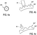
- the Figures 4a, 4b and 4c show a possible embodiment of the toothed disk 200 with a toothing 202, which is arranged on a radial circumferential surface of the toothed disk 200.
- the toothing 202 can also be referred to as a radial external toothing.
- the tooth lock washer 200 'in Figure 4b has a triangular toothing 202 '.
- a locking element 50 corresponding to this triangular toothing 202 ′ is shown.
- the locking element 50 has a triangular engagement area which is essentially a negative geometry of the locking recess of the toothing 202 '.
- Such a locking element 50 can also be referred to as a wedge shape.
- Figure 4c is an alternative to the embodiment in Figure 4b shown, with a toothed washer 200 ′′ and a toothing 202 ′′, which has a wave profile or a shaft toothing.
- a locking element 60 corresponding to this wave profile 202 ′′ has an engagement area which has a round geometry.
- Such a locking element can, for example, have the geometry of a roller, so that the aforementioned round geometry for engaging the toothing 202 ′′ is provided in a corresponding cross section can.
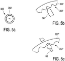
- Embodiments of the rotor locking device are shown as are possible with a toothed disk 300, the toothed disk 300 having a toothing 302 on a radial inner circumferential surface.
- a wedge-shaped locking element 50 can engage in such an internal toothing 302 'of a toothed disk 300'.
- Figure 5c is shown as a cylindrical Locking element 60 with a circular cross-section can engage in a wave profile 302 "of a toothed disk 300".
- the toothed disk 400 has a toothing 402 on one end face, so that the tooth heights of the toothing are aligned essentially parallel to an axis of rotation R of the rotating disk 400.
- the embodiment is shown how a wedge-shaped locking element 50 can engage in the toothing 402 'of the toothed disk 400'.
- the embodiment for a toothed washer 400 ′′ having a shaft toothing 402 ′′ with a cylindrical locking element 60 is shown.
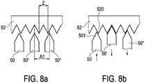
- FIGs 7a and 7b shows the difference between an engaged position and a standby position.
- Figure 7a it is shown how a wedge-shaped locking element 50 is arranged relative to a toothed washer 52 in a standby position.
- Figure 7b it is shown how the toothed washer 52 and the locking element 50 are arranged when the locking element 50 is in an engaged position.
- the toothed disk 52 is rotated here in the direction of the further locking elements 50, 50 '.
- the locking elements 50' and 50 are switched powerless or moved in an opposite direction from locking element 50 so that they no longer lock the toothed disk.
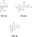
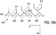
- FIGS. 10a-e show schematic views of a further exemplary embodiment of an exemplary embodiment of a rotor locking device with three locking elements in different positions of a method for locking and / or rotating a rotor of a wind energy installation.
- the first arrangement shown is a first locking element 611, a second locking element 612 and a third locking element 613 in a standby position. In the standby position, the locking elements 611, 612, 613 are not arranged in one of the recesses of a toothed disk 600.
- the recesses of the toothed disk 600 are at least formed by a first tooth 601, a second tooth 602 arranged adjacent to this, a third tooth 603 arranged adjacent to this, a fourth tooth 604 arranged adjacent to this, a fifth tooth 605 arranged adjacent to this, and a sixth tooth 606 arranged adjacent to this is formed.
- the teeth 601-606 each have a cross section orthogonally to the circumferential direction U and orthogonally to the radial direction RA of the toothed disk 600, the cross section having the geometry of an isosceles triangle. The height of the isosceles triangle is aligned in the radial direction.
- the cross section of the teeth 601-606 is also designed such that the locking recesses formed by the teeth 601-606 have the same cross-sectional geometry as the teeth 601-606.
- the locking elements 611, 612, 613 also have a triangular geometry at their ends facing the toothed disk 600 or in their areas adjacent to these ends.
- the locking elements 611, 612, 613 here have a geometry that forms a negative of the recesses, so that the locking elements with these areas can be arranged essentially completely in the recesses.
- the teeth 601-606 are equidistant from one another, so that the recesses are also equidistant from one another.
- the locking elements 611, 612, 613 are also equidistantly spaced from one another, the spacing of two locking elements is a non-integer multiple of a tooth tip distance between two adjacent teeth. As a rule, there is therefore no possibility of two locking elements being in an engaged position at the same time.
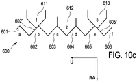
- the first locking element 611 is in an engagement position between the first tooth 601 and the second tooth 602. This arrangement prevents the toothed disk 600 from rotating in the circumferential direction U.
- the second locking element 612 is located in a position which is arranged in the radial direction RA between an engagement position and a standby position. In this position, the second locking element 612 is tangent to the tooth flank 603 ′ of the third tooth 603 facing away from the second tooth 602.
- the third locking element 613 is still in a standby position.
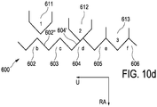
- the first locking element 611 is actively withdrawn such that it continuously shears on a tooth flank 602 ′ of the second tooth 602 facing the first tooth 601 when it is withdrawn.
- the third locking element 613 is located in a position which is arranged in the radial direction RA between an engagement position and a standby position. In this position, the third locking element 613 is tangent to the tooth flank 605 ′ of the fifth tooth 605 facing away from the fourth tooth 604.
- the rotor locking device shown here has the particular advantage, because of the claimed distance A1 of the locking elements compared to the tooth tip distance Z, that it can incrementally rotate a toothed disk in a tangential direction and thus also rotate the aerodynamic rotor of a wind turbine in small steps. Essentially any desired positioning of the aerodynamic rotor can thus be achieved. In addition, with such a positioning, care can be taken to ensure that, in particular, positions that are desirable for maintenance and / or assembly and / or disassembly steps can be achieved. In addition, by providing a plurality of locking modules 120, 130, 140, 25, 26, 27, the possibility can be created that the toothed disk is moved in a first direction of rotation and in a second direction of rotation opposite to this. In addition, the geometry of the locking elements, which cause a shearing movement in the toothing of the toothed disk, prevents jamming during locking. This also ensures improved releasability of the lock.
Description
Die Erfindung betrifft eine Rotorarretiervorrichtung für eine Windenergieanlage, eine Windenergieanlage sowie ein Verfahren zum Arretieren und/oder Drehen eines Rotors einer Windenergieanlage.The invention relates to a rotor locking device for a wind power plant, a wind power plant and a method for locking and / or rotating a rotor of a wind power plant.
Eine Windenergieanlage wandelt die Energie des Windes in elektrische Energie um. Die dominierende Bauform von Windenergieanlagen ist die dreiblättrige HorizontalachsenWindenergieanlage, bei der sich im Betrieb der Rotor auf der Luvseite befindet und deren Maschinenhaus auf einem Turm angeordnet ist und der Windrichtung aktiv nachgeführt wird.A wind turbine converts the energy of the wind into electrical energy. The dominant design of wind turbines is the three-bladed horizontal axis wind turbine, in which the rotor is on the windward side during operation and the machine house is arranged on a tower and the wind direction is actively tracked.
Der aerodynamische Rotor der Windenergieanlage umfasst vorzugsweise ein, zwei oder mehrere Rotorblätter, die vorzugsweise an einer gemeinsamen Nabe befestigt sind. Diese Nabe ist ferner vorzugsweise drehsteif mit einer Rotationsbaugruppe verbunden. Bei Windenergieanlagen mit einem Direktantrieb, das heißt ohne ein Getriebe zur Übersetzung, treibt der Rotor beispielsweise über die Nabe und einen Achszapfen einen Generatorrotor an. Die Rotationsbaugruppe umfasst bei Windenergieanlagen mit Getriebe in der Regel ferner eine Rotorwelle, welche den Rotor und ein Getriebe miteinander verbindet. Somit wird die Drehbewegung des Rotors durch das Getriebe in eine Getriebeabtriebsbewegung umgewandelt, so dass anschließend diese Getriebeabtriebsbewegung wiederum an einen Generator übertragen werden kann.The aerodynamic rotor of the wind energy installation preferably comprises one, two or more rotor blades, which are preferably attached to a common hub. This hub is also preferably connected in a torsionally rigid manner to a rotary assembly. In wind turbines with a direct drive, that is to say without a gearbox for transmission, the rotor drives a generator rotor, for example via the hub and an axle journal. In wind turbines with a gearbox, the rotary assembly also generally includes a rotor shaft which connects the rotor and a gearbox to one another. The gearbox converts the rotary movement of the rotor into a gearbox output movement so that this gearbox output movement can then be transmitted to a generator.
Als Rotor wird im Sinne dieser Anmeldung der aerodynamische Rotor einer Windenergieanlage mit in der Regel drei Rotorblättern verstanden. Als Generatorrotor wird im Sinne dieser Anmeldung ein elektrodynamischer Rotor eines Generators verstanden, vorzugsweise eines Generators für eine Windenergieanlage. Ein Generator im Sinne dieser Anmeldung umfasst sowohl Innenläufergeneratoren, bei denen ein Generatorrotor radial innerhalb eines Stators rotiert, als auch Außenläufergeneratoren, bei denen ein Generatorrotor radial außerhalb um einen Stator rotiert. Der aerodynamische Rotor einer Windenergieanlage ist in verschiedenen Situationen zu arretieren, wobei es ferner bevorzugt ist, dass der Rotor in einer spezifischen Drehposition arretiert wird.In the context of this application, the rotor is understood to be the aerodynamic rotor of a wind energy installation with, as a rule, three rotor blades. In the context of this application, a generator rotor is understood to be an electrodynamic rotor of a generator, preferably of a generator for a wind energy installation. A generator within the meaning of this application includes both internal rotor generators, in which a generator rotor rotates radially inside a stator, and external rotor generators, in which a generator rotor rotates radially outside around a stator. The aerodynamic rotor of a wind turbine is to be locked in various situations, it being further preferred that the rotor is locked in a specific rotational position.
Beispielsweise kann es erforderlich sein, dass der Rotor arretiert wird, um Reparatur- und/oder Wartungsarbeiten, beispielsweise im Inneren der Gondel oder im Bereich der Nabe, durchzuführen. Ferner kann es erforderlich werden, den Rotor zu arretieren, sobald die Windenergieanlage montiert und/oder demontiert wird. Beispielsweise entstehen hohe Arretierkräfte und/oder Arretiermomente zum Halten eines Rotors in einer definierten Position, wenn nicht alle vorgesehenen Rotorblätter angeordnet sind und sich der Rotor somit in einer labilen Position befindet. Dies ist insbesondere in der zweckmäßigen und sogenannten Sechs-Uhr-Position notwendig, indem ein Nabenanschlussbereich, an dem kein Rotorblatt angeordnet ist, in Richtung des Fundamentes der Windenergieanlage zeigt und die vorzugsweise bereits montierten zwei weiteren Rotorblätter teilweise in eine entgegengesetzte Richtung mit ihrer Längsachse zeigen. Dadurch bewirken die nicht gleichmäßig um eine Rotationsachse angeordneten Rotorblätter ein hohes Drehmoment in Bezug auf diese Rotationsachse.For example, it may be necessary for the rotor to be locked in order to carry out repair and / or maintenance work, for example inside the nacelle or in the area of the hub. It may also be necessary to lock the rotor as soon as the wind energy installation is assembled and / or disassembled. For example, high locking forces and / or locking torques arise for holding a rotor in a defined position if not all the rotor blades provided are arranged and the rotor is thus in an unstable position. This is particularly necessary in the practical and so-called six o'clock position, in that a hub connection area on which no rotor blade is arranged points in the direction of the foundation of the wind turbine and the two further rotor blades, which are preferably already installed, partially point in an opposite direction with their longitudinal axis . As a result, the rotor blades, which are not arranged uniformly about an axis of rotation, produce a high torque in relation to this axis of rotation.
Sobald die vorherrschende Windgeschwindigkeit die maximale Windgeschwindigkeit für die Windenergieanlage überschreitet, kann es ferner vorteilhaft sein, nicht nur den Anstellwinkel der Rotorblätter zu verändern, um den Rotor abzubremsen, sondern den Rotor der Windenergieanlage zum Stillstand zu bringen, also auf eine Drehzahl von Null abzubremsen und im Anschluss derart zu arretieren, dass der Rotor an einer Drehung gehindert ist. Ferner ist es häufig erforderlich, dass der Rotor mit einer hohen Präzision in einer gewünschten Position arretiert wird, sodass positionsabhängige Reparaturen und/oder Wartungsarbeiten und/oder Montagearbeiten durchgeführt werden können.As soon as the prevailing wind speed exceeds the maximum wind speed for the wind turbine, it can also be advantageous not only to change the angle of attack of the rotor blades in order to brake the rotor, but also to bring the rotor of the wind turbine to a standstill, i.e. to brake it to a speed of zero and then to be locked in such a way that the rotor is prevented from rotating. Furthermore, it is often necessary for the rotor to be locked in a desired position with great precision, so that position-dependent repairs and / or maintenance work and / or assembly work can be carried out.
Im Stand der Technik bekannte Rotorarretiervorrichtungen haben insbesondere das Ziel, eine sichere Arretierung bereitzustellen. Dies erklärt sich insbesondere dadurch, dass durch entsprechende Sicherheitsvorkehrungen für an der Windenergieanlage arbeitende Personen gesorgt sein sollte. Daher sind bei im Stand der Technik bekannten Rotorarretiervorrichtungen vornehmlich Kombinationen aus Bolzen und vorzugsweise mehreren Öffnungen vorgesehen. Ferner vorzugsweise sind an einem Generatorrotor eines Generators, insbesondere an einem Rotorträger, Öffnungen angeordnet, deren Durchtrittsrichtung vorzugsweise im Wesentlichen parallel zu einer Rotationsachse des Generators angeordnet ist. Am Generatorstator, insbesondere an einem Statorträger, sind vorzugsweise zu den Öffnungen korrespondierende Bolzen angeordnet, die in den Öffnungen angeordnet werden können. Durch die Anordnung der Bolzen innerhalb der Öffnungen kann eine Arretierung des Generatorrotors und somit auch des aerodynamischen Rotors erreicht werden.Rotor locking devices known in the prior art have the particular aim of providing secure locking. This is explained in particular by the fact that appropriate safety precautions for those working on the wind energy installation Individuals should be taken care of. Therefore, in the case of rotor locking devices known in the prior art, primarily combinations of bolts and preferably several openings are provided. Furthermore, openings are preferably arranged on a generator rotor of a generator, in particular on a rotor carrier, the direction of passage of which is preferably arranged essentially parallel to an axis of rotation of the generator. On the generator stator, in particular on a stator carrier, bolts that correspond to the openings are preferably arranged, which bolts can be arranged in the openings. By arranging the bolts within the openings, a locking of the generator rotor and thus also of the aerodynamic rotor can be achieved.
Eine im Vorherigen genannte und beschriebene Rotorarretiervorrichtung kann zwar einerseits eine sichere Arretierung des Rotors bereitstellen, allerdings ist eine Positionierung des Rotors nur auf den Positionen möglich, an denen Öffnungen an der Rotationsbaugruppe vorgesehen sind. Ferner ist es beispielsweise zur Montage von Rotorblättern erforderlich, nach der Montage eines ersten Rotorblatts die Arretierung zu lösen, um den Rotor in die Position für die Montage des zweiten Rotorblatts, vorzugsweise in eine Sechs-Uhr-Position, zu drehen und dort abermals zu arretieren. Dies resultiert in verschiedensten Anwendungsbereichen in hohen Kosten und einem großen Aufwand. Die existierenden Systeme und Verfahren zum Arretieren von Windenergieanlagenrotoren bieten zwar verschiedene Vorteile, jedoch sind weitere Verbesserungen wünschenswert.A rotor locking device mentioned and described above can, on the one hand, provide a secure locking of the rotor, but positioning of the rotor is only possible in the positions at which openings are provided on the rotary assembly. Furthermore, for example, to assemble rotor blades, it is necessary to release the lock after assembling a first rotor blade in order to turn the rotor into the position for assembling the second rotor blade, preferably in a six o'clock position, and to lock it there again . This results in high costs and great effort in a wide variety of application areas. While the existing systems and methods for locking wind turbine rotors offer various advantages, further improvements are desirable.
Das Deutsche Patent- und Markenamt hat in der Prioritätsanmeldung zu vorliegender Anmeldung folgenden Stand der Technik recherchiert:
Es ist daher eine Aufgabe der vorliegenden Erfindung, eine Lösung bereitzustellen, welche einen oder mehrere der genannten Nachteile vermindert oder beseitigt. Ferner ist es eine Aufgabe der vorliegenden Erfindung, eine Lösung bereitzustellen, welche eine kostengünstigere und/oder einfachere Montage und/oder Wartung und/oder Reparatur einer Windenergieanlage ermöglicht. Darüber hinaus ist es eine Aufgabe der vorliegenden Erfindung, eine Lösung bereitzustellen, welche die Arretierung einer Windenergieanlage verbessert und/oder vereinfacht.It is therefore an object of the present invention to provide a solution which reduces or eliminates one or more of the disadvantages mentioned. Furthermore, it is an object of the present invention to provide a solution which enables a more cost-effective and / or simpler assembly and / or maintenance and / or repair of a wind energy installation. In addition, it is an object of the present invention to provide a solution which improves and / or simplifies the locking of a wind energy installation.
Gemäß einem ersten Aspekt der vorliegenden Erfindung wird die eingangs genannte Aufgabe gelöst durch eine Rotorarretiervorrichtung für eine Windenergieanlage mit einem Rotor, einer mit dem Rotor drehsteif verbundenen Rotationsbaugruppe und einer relativ zur Rotationsbaugruppe ortsfesten Standbaugruppe, umfassend eine an der Rotationsbaugruppe anordenbare Zahnscheibe, mit einer entlang eines Umfangs angeordneten Mehrzahl an Arretierausnehmungen, wobei zwei benachbarte Arretierausnehmungen einen Zahn ausbilden, ein erstes Arretiermodul mit mindestens einem ersten Arretierelement, ein zweites Arretiermodul mit mindestens einem zweiten Arretierelement, wobei das erste Arretiermodul und das zweite Arretiermodul an der Standbaugruppe anordenbar sind, wobei das erste Arretierelement und das zweite Arretierelement angeordnet und ausgebildet sind, in Arretierausnehmungen der Zahnscheibe einzugreifen, wobei in Umfangsrichtung der Zahnscheibe der Abstand des mindestens einen ersten Arretierelements von dem mindestens einen zweiten Arretierelement ein nicht ganzzahliges Vielfaches eines Zahnspitzenabstands der Zahnscheibe beträgt.According to a first aspect of the present invention, the object mentioned at the beginning is achieved by a rotor locking device for a wind energy installation with a A rotor, a rotationally rigidly connected to the rotor rotation assembly and a stationary assembly relative to the rotation assembly, comprising a toothed disk that can be arranged on the rotation assembly, with a plurality of locking recesses arranged along a circumference, two adjacent locking recesses forming a tooth, a first locking module with at least one first Locking element, a second locking module with at least one second locking element, wherein the first locking module and the second locking module can be arranged on the stand assembly, wherein the first locking element and the second locking element are arranged and designed to engage in locking recesses of the toothed disk, wherein the toothed disk is in the circumferential direction of the The distance between the at least one first locking element and the at least one second locking element is a non-integer multiple of a tooth tip distance of the toothed disk.
Die Rotationsbaugruppe ist drehsteif mit dem Rotor verbunden. Wenn nicht explizit anders beschrieben, ist unter einem Rotor die Baugruppe umfassend mindestens ein Rotorblatt, eine Nabe, an der das mindestens eine Rotorblatt angeordnet ist, zu verstehen. Oft weist der Rotor auch einen Spinner auf. Die Rotationsbaugruppe kann beispielsweise einen Rotorträger und/oder einen Achszapfen und/oder eine Rotorwelle umfassen, welcher bzw. welche drehsteif mit der Rotornabe verbunden ist. Vorzugsweise kann die Rotationsbaugruppe auch einen Generatorrotor umfassen. Ferner vorzugsweise umfasst die Rotationsbaugruppe jegliches Bauteil, das mittels einer Drehung des Rotors ebenfalls in eine Drehbewegung versetzt wird.The rotary assembly is torsionally rigidly connected to the rotor. Unless explicitly described otherwise, a rotor is understood to mean the assembly comprising at least one rotor blade, a hub on which the at least one rotor blade is arranged. Often the rotor also has a spinner. The rotary assembly can comprise, for example, a rotor carrier and / or an axle journal and / or a rotor shaft which is connected to the rotor hub in a torsionally rigid manner. The rotary assembly can preferably also comprise a generator rotor. Furthermore, the rotary assembly preferably comprises any component that is also set into rotary motion by means of a rotation of the rotor.
Neben der Rotationsbaugruppe umfasst eine Windenergieanlage eine Standbaugruppe, welche gegenüber der Rotationsbaugruppe ortsfest ist. Die Standbaugruppe umfasst insbesondere derartige Elemente, die innerhalb der Gondel angeordnet sind und die um eine Rotationsachse des Rotors keine Rotationsbewegung ausführen. Die Standbaugruppe ist somit gegenüber der Rotationsbaugruppe ortsfest. Gegenüber dem Turm und/oder dem Fundament der Windenergieanlage ist die Standbaugruppe zusammen mit der Gondel in der Regel jedoch um eine im Wesentlichen vertikale Achse drehbar, da Windenergieanlagen in der Regel eine Windrichtungsnachführung aufweisen, sodass die Gondel um eine Achse parallel zur Längsachse des Turmes rotieren kann. Somit rotiert auch die Standbaugruppe, welche innerhalb der Gondel angeordnet ist, gegenüber einem Punkt außerhalb der Gondel, insbesondere gegenüber dem Boden, auf dem die Windenergieanlage errichtet ist. Ortsfest ist im Sinne dieser Anmeldung in Bezug auf die rotierende Rotationsbaugruppe zu verstehen. Die Standbaugruppe umfasst beispielsweise einen Generatorstator, einen Achszapfen, einen Maschinenträger, ein Generatorgehäuse oder ein Getriebegehäuse. Ferner vorzugsweise umfasst die Standbaugruppe ein Element, an dem die Arretiermodule anordenbar sind.In addition to the rotating assembly, a wind power installation includes a standing assembly which is stationary with respect to the rotating assembly. The stand assembly comprises in particular elements of this type which are arranged within the nacelle and which do not perform any rotational movement about an axis of rotation of the rotor. The stand assembly is therefore stationary with respect to the rotation assembly. Compared to the tower and / or the foundation of the wind turbine, however, the stand assembly together with the nacelle can usually be rotated around an essentially vertical axis, since wind turbines generally have a wind direction tracking system, so that the nacelle rotate around an axis parallel to the longitudinal axis of the tower can. The stand assembly, which is arranged inside the nacelle, thus also rotates with respect to a point outside the nacelle, in particular with respect to the ground on which the wind power installation is erected. In the context of this application, stationary is to be understood in relation to the rotating rotary assembly. The stand assembly includes for example a generator stator, a journal, a machine carrier, a generator housing or a gear housing. Furthermore, the stand assembly preferably comprises an element on which the locking modules can be arranged.
Die an der Rotationsbaugruppe anordenbare Zahnscheibe weist entlang eines Umfangs eine Mehrzahl an Arretierausnehmungen auf. Die Zahnscheibe kann entweder ein eigens für die Rotorarretierung vorgesehenes Element, das drehsteif an der Rotationsbaugruppe angeordnet ist, sein, oder alternativ kann die Zahnscheibe auch an einem bekannten Element der Rotationsbaugruppe angeordnet sein. Beispielsweise kann die Zahnscheibe ein Teil einer Generatorrotorscheibe sein, indem die Generatorrotorscheibe entlang eines Umfangs angeordnete Arretierausnehmungen aufweist. Durch die Mehrzahl an Arretierausnehmungen entlang des Umfangs der Zahnscheibe wird eine Verzahnung ausgebildet.The toothed disk that can be arranged on the rotary assembly has a plurality of locking recesses along a circumference. The toothed washer can either be an element which is provided specifically for the rotor locking and which is arranged in a torsionally rigid manner on the rotary assembly, or alternatively the toothed washer can also be arranged on a known element of the rotary assembly. For example, the toothed disk can be part of a generator rotor disk in that the generator rotor disk has locking recesses arranged along a circumference. A tooth system is formed by the plurality of locking recesses along the circumference of the toothed disk.
Die Verzahnung kann beispielsweise ein Wellenprofil aufweisen, das sich dadurch auszeichnet, dass die Ausnehmungen und/oder die Zähne eine teilkreisförmige, insbesondere halbkreisförmige, Geometrie aufweisen. Ferner vorzugsweise kann die Verzahnung eine Evolventen- und/oder Zykloidenverzahnung aufweisen. Darüber hinaus kann auch eine Sägezahnverzahnung vorgesehen werden. Die Arretierausnehmungen bzw. die durch die Arretierausnehmungen ausgebildeten Zähne müssen jedoch eine derartige Geometrie aufweisen, dass das mindestens eine erste Arretierelement und das mindestens eine zweite Arretierelement, trotz des erfindungsgemäßen Abstandes dieser zwei Arretierelemente zueinander, stets in einer der Arretierausnehmungen anordenbar sind. Insbesondere sind die Arretierelemente bzw. die Arretierausnehmungen derart zu gestalten, dass beim Bewegen eines Arretierelements in eine Arretierausnehmung gegebenenfalls eine Scherbewegung stattfindet, sodass durch das Bewegen der Zahnscheibe eine Anordnung eines Arretierelements bzw. eines Abschnitts eines Arretierelements in einer Arretierausnehmung ermöglicht wird.The toothing can, for example, have a wave profile, which is characterized in that the recesses and / or the teeth have a partially circular, in particular semicircular, geometry. Furthermore, the toothing can preferably have an involute and / or cycloid toothing. In addition, a saw tooth system can be provided. However, the locking recesses or the teeth formed by the locking recesses must have such a geometry that the at least one first locking element and the at least one second locking element can always be arranged in one of the locking recesses, despite the spacing of these two locking elements according to the invention. In particular, the locking elements or the locking recesses are to be designed in such a way that when a locking element is moved into a locking recess, a shearing movement may take place so that moving the toothed washer enables a locking element or a section of a locking element to be arranged in a locking recess.
Das mindestens eine erste Arretierelement ist an dem ersten Arretiermodul angeordnet. Das erste Arretierelement erstreckt sich vorzugsweise von einem Modulende zu einem Eingriffsende. Mit dem Modulende ist das erste Arretierelement vorzugsweise an und/oder in dem ersten Arretiermodul angeordnet. Vorzugsweise ist das erste Arretierelement an dem ersten Arretiermodul derart angeordnet, dass das erste Arretierelement relativ zum Arretiermodul bewegt werden kann. Das Eingriffsende des ersten Arretierelements ist vorzugsweise dem Arretiermodul abgewandt und im Betriebszustand der Zahnscheibe zugewandt. Vorzugsweise weist ein Bereich angrenzend an das Eingriffsende eine Geometrie auf, welche eine Negativgeometrie der Arretierausnehmungen darstellt. Ferner vorzugsweise weist ein Bereich angrenzend an das Eingriffsende eine Geometrie auf, die zumindest teilweise eine Negativgeometrie der Arretierausnehmungen darstellt. Insbesondere ist ein Bereich angrenzend an das Eingriffsende derart ausgebildet, sodass beim Hineinführen eines Arretierelements in eine Arretierausnehmung, welches nicht exakt mittig erfolgt, eine Scherbewegung und somit auch eine Scherkraft, insbesondere in tangentialer Richtung der Zahnscheibe, entsteht. Somit kann vorzugsweise gewährleistet werden, dass im Falle einer nicht exakt mittigen Einführung eines Arretierelements in eine Arretierausnehmung eine inkrementelle Bewegung der Zahnscheibe bzw. des Rotors erfolgt und somit das Arretierelement durch diese inkrementelle Bewegung dann mittig eingreift und eine sichere Rotorarretierung gewährleistet werden kann. Ferner resultiert diese Anordnung des ersten Arretierelements darin, dass auf die mit der Zahnscheibe verbundene Baugruppe eine Scherkraft ausgeübt und eine Drehung dieser Baugruppe relativ zu dem ersten Arretierelement ermöglicht werden kann. Im Falle einer Anordnung der Baugruppe an einer Rotationsbaugruppe einer Windenergieanlage kann somit eine Drehung der Rotationsbaugruppe bzw. des Rotors ermöglicht werden.The at least one first locking element is arranged on the first locking module. The first locking element preferably extends from a module end to an engagement end. With the module end, the first locking element is preferably arranged on and / or in the first locking module. The first locking element is preferably arranged on the first locking module in such a way that the first locking element can be moved relative to the locking module. The engagement end of the first locking element is preferably facing away from the locking module and, in the operating state, facing the toothed disk. Preferably has an area adjacent to the engagement end a geometry which represents a negative geometry of the locking recesses. Furthermore, a region adjoining the engagement end preferably has a geometry which at least partially represents a negative geometry of the locking recesses. In particular, an area adjacent to the engagement end is designed in such a way that when a locking element is inserted into a locking recess that does not take place exactly in the center, a shear movement and thus also a shear force, in particular in the tangential direction of the toothed disk, arise. In this way, it can preferably be ensured that in the event of a locking element not being inserted exactly in the center into a locking recess, an incremental movement of the toothed disc or rotor takes place and the locking element then engages in the center through this incremental movement and a secure rotor locking can be ensured. Furthermore, this arrangement of the first locking element results in the fact that a shear force is exerted on the assembly connected to the toothed washer and rotation of this assembly relative to the first locking element can be made possible. In the case of an arrangement of the assembly on a rotation assembly of a wind energy installation, a rotation of the rotation assembly or the rotor can thus be made possible.
Diese Ausführungen gelten im Wesentlichen analog für das zweite Arretiermodul und das mindestens eine zweite Arretierelement.These statements essentially apply analogously to the second locking module and the at least one second locking element.
Das erste Arretiermodul und das zweite Arretiermodul sind erfindungsgemäß an einer Standbaugruppe einer Windenergieanlage anordenbar. Das erste Arretiermodul und das zweite Arretiermodul sind vorzugsweise und im Wesentlichen nicht in Rotationsrichtung der Rotationsbaugruppe beweglich. Vorzugsweise ist bzw. sind das mindestens eine erste Arretierelement und/oder das mindestens eine zweite Arretierelement ebenfalls bezüglich einer Rotationsrichtung der Rotationsbaugruppe fest angeordnet. Insbesondere ist diese feste Anordnung des mindestens einen ersten Arretierelements und/oder des mindestens einen zweiten Arretierelements an dem ersten Arretiermodul bzw. dem zweiten Arretiermodul derart gestaltet, dass diese in Arretierausnehmungen der Zahnscheibe eingreifen können. Zu diesem Zweck sind die Arretierelement an den Arretiermodulen vorzugsweise in Richtung der Zahnscheibe bewegbar angeordnet. Darüber hinaus besteht die Möglichkeit, dass die Arretierelemente an den Arretiermodulen fest angeordnet sind, jedoch die Arretiermodule mit den fest an diesen angeordneten Arretierelementen in Richtung der Zahnscheibe beweglich ausgebildet sind.According to the invention, the first locking module and the second locking module can be arranged on a stand assembly of a wind turbine. The first locking module and the second locking module are preferably and essentially not movable in the direction of rotation of the rotating assembly. Preferably, the at least one first locking element and / or the at least one second locking element is / are also arranged fixedly with respect to a direction of rotation of the rotary assembly. In particular, this fixed arrangement of the at least one first locking element and / or the at least one second locking element on the first locking module or the second locking module is designed such that they can engage in locking recesses of the toothed disk. For this purpose, the locking elements on the locking modules are preferably arranged to be movable in the direction of the toothed disk. In addition, there is the possibility that the locking elements are fixedly arranged on the locking modules, but the locking modules with the locking elements fixedly arranged on them are designed to be movable in the direction of the toothed disk.
Unter einem Eingreifen eines Arretierelements in eine Arretierausnehmung ist insbesondere zu verstehen, dass das Arretierelement derart in der Arretierausnehmung der Zahnscheibe angeordnet ist, dass die Zahnscheibe weder in eine erste Drehrichtung noch in eine zweite Drehrichtung bewegbar ist. Unberücksichtigt bleiben bei dieser Definition eventuell notwendige Kräfte zum Arretieren, sodass eventuell auch das Eingreifen von zwei oder mehreren Arretierelementen vollständig in mehreren Arretierausnehmungen notwendig ist, um eine sichere Rotorarretierung zu gewährleisten.An engagement of a locking element in a locking recess is to be understood in particular to mean that the locking element is arranged in the locking recess of the toothed disk in such a way that the toothed disk can neither be moved in a first direction of rotation nor in a second direction of rotation. This definition does not take into account any forces necessary for locking, so that it may also be necessary for two or more locking elements to fully engage in several locking recesses in order to ensure secure rotor locking.
In Umfangsrichtung der Zahnscheibe weist das mindestens eine erste Arretierelement von dem mindestens einen zweiten Arretierelement einen Abstand auf, der ein nicht ganzzahliges Vielfaches eines Zahnspitzenabstands der Zahnscheibe beträgt. Ein Zahnspitzenabstand ist insbesondere als der Abstand zu verstehen, den zwei Zahnhochpunkte von zwei benachbarten Zähnen aufweisen. Bei einer homogenen Verzahnung ist dieser Zahnspitzenabstand entlang der gesamten Zahnscheibe konstant. Darüber hinaus können auch Zahnscheiben vorgesehen werden, deren Verzahnung nicht konstant ist. Bei einer derartigen Verzahnung besteht zusätzlich die Möglichkeit, dass Zahnspitzenabstandsbereiche definiert werden, wobei die Zahnspitzenabstandsbereiche jeweils vorzugsweise einen konstanten Zahnspitzenabstand aufweisen. Darüber hinaus kann der Zahnspitzenabstand durch das Vorsehen einzelner größerer Zähne abschnittsweise nicht konstant sein.In the circumferential direction of the toothed disk, the at least one first locking element is at a distance from the at least one second locking element which is a non-integer multiple of a tooth tip distance of the toothed disk. A tooth tip distance is to be understood in particular as the distance that two tooth high points have from two adjacent teeth. In the case of a homogeneous toothing, this tooth tip spacing is constant along the entire toothed disk. In addition, toothed disks can also be provided whose toothing is not constant. With such a toothing there is also the possibility of defining tooth tip spacing areas, the tooth tip spacing areas each preferably having a constant tooth tip spacing. In addition, the provision of individual larger teeth means that the tooth tip spacing cannot be constant in sections.
Durch die Beabstandung des mindestens einen ersten Arretierelements und des mindestens einen zweiten Arretierelements wird deutlich, dass das mindestens eine erste Arretierelement und das mindestens eine zweite Arretierelement nicht gleichzeitig vollständig in eine Arretierausnehmung eingreifen können. Im Falle, dass das mindestens eine erste Arretierelement vollständig in eine Arretierausnehmung eingreift, greift das mindestens eine zweite Arretierelement nicht vollständig in eine weitere Arretierausnehmung ein. Jedoch ist ein teilweises Eingreifen des mindestens einen zweiten Arretierelements in eine Arretierausnehmung möglich. In dieser Situation kann das zweite Arretierelement weiter in Richtung der Zahnscheibe bewegt werden und somit in Richtung einer Eingriffsposition. Durch eine entsprechende Ausbildung der Arretierausnehmung und der Arretierelemente bzw. deren Eingriffsbereiche erfolgt eine Scherbewegung, sodass sich die Zahnscheibe und somit auch die Verzahnung tangential bewegt, sodass das mindestens eine zweite Arretierelement vollständig in eine Arretierausnehmung eingreifen kann. Es erschließt sich, dass durch das vollständige Eingreifen des mindestens einen zweiten Arretierelements in eine Arretierausnehmung sowie durch die tangentiale Bewegung der Zahnscheibe das mindestens eine erste Arretierelement nicht mehr vollständig in der zuvor angeordneten Arretierausnehmung angeordnet sein kann. Das mindestens eine erste Arretierelement wird in dieser Situation entweder kraftlos geschaltet und durch die Bewegung der Zahnscheibe ebenfalls durch eine Scherbewegung aus der Eingriffsposition heraus gedrängt, oder alternativ wird das mindestens ein erstes Arretierelement aktiv zurückgezogen beispielsweise mittels eines Antriebs.The spacing of the at least one first locking element and the at least one second locking element makes it clear that the at least one first locking element and the at least one second locking element cannot fully engage a locking recess at the same time. In the event that the at least one first locking element fully engages in a locking recess, the at least one second locking element does not fully engage in a further locking recess. However, partial engagement of the at least one second locking element in a locking recess is possible. In this situation, the second locking element can be moved further in the direction of the toothed disk and thus in the direction of an engagement position. A corresponding design of the locking recess and the locking elements or their engagement areas results in a shearing movement so that the toothed disk and thus also the toothing move tangentially so that the at least one second locking element can fully engage in a locking recess. It becomes apparent that the at least one first locking element as a result of the complete engagement of the at least one second locking element in a locking recess and the tangential movement of the toothed disk Locking element can no longer be arranged completely in the previously arranged locking recess. In this situation, the at least one first locking element is either switched to a powerless state and also pushed out of the engagement position by the movement of the toothed disk, or alternatively the at least one first locking element is actively withdrawn, for example by means of a drive.
Unter einer Windenergieanlage wird vorliegend insbesondere eine Horizontalachsenwindenergieanlage verstanden, die insbesondere dadurch gekennzeichnet ist, dass der Rotor im Betrieb eine Fläche überstreicht, die im Wesentlichen vertikal zur Erdoberfläche ausgerichtet ist, und eine Rotorachse aufweist, die im Wesentlichen eine horizontale Ausrichtung aufweist. Solche Windenergieanlagen werden auch als Horizontalachsen-Windenergieanlagen bezeichnet. Ferner wird unter einer Windenergieanlage insbesondere eine Windenergieanlage mit einer Nennleistung von mehr als 500 kW, und/oder mehr als 1000 kW, und/oder mehr als 1500 kW, und/oder mehr als 2000 kW, und/oder mehr als 2500 kW, und/oder mehr als 3000 kW, und/oder mehr als 3500 kW, und/oder mehr als 4000 kW, und/oder mehr als 4500 kW, und/oder mehr als 5000 kW, und/oder mehr als 5500 kW, und/oder mehr als 6000 kW verstanden.In the present case, a wind energy installation is understood in particular to be a horizontal axis wind energy installation, which is particularly characterized in that, during operation, the rotor sweeps over an area that is essentially oriented vertically to the earth's surface and has a rotor axis that is essentially horizontal. Such wind turbines are also referred to as horizontal-axis wind turbines. Furthermore, a wind energy installation is in particular a wind energy installation with a nominal power of more than 500 kW, and / or more than 1000 kW, and / or more than 1500 kW, and / or more than 2000 kW, and / or more than 2500 kW, and / or more than 3000 kW, and / or more than 3500 kW, and / or more than 4000 kW, and / or more than 4500 kW, and / or more than 5000 kW, and / or more than 5500 kW, and / or understood more than 6000 kW.
Der Erfindung liegt die Erkenntnis zugrunde, dass das im Stand der Technik bekannte Arretieren in vielen Fällen nicht ausreichend ist, um eine gewünschte Position des Rotors zu erreichen. Durch eine Verzahnung an einer Zahnscheibe, welche drehsteif mit einer Rotationsbaugruppe verbunden ist, sowie Arretierelemente, die in diese Verzahnung eingreifen können, welche wiederum fest an einer Standbaugruppe angeordnet sind, kann die Auflösung einer Drehpositionierung deutlich verbessert werden. Ferner liegt der Erfindung die Erkenntnis zugrunde, dass durch entsprechend geformte Arretierelemente und korrespondierend ausgebildete Arretierausnehmungen eine Scherkraft zwischen der Zahnscheibe und den Arretierelementen in tangentialer Richtung der Zahnscheibe erzielt werden kann, sodass eine inkrementelle Drehung der Zahnscheibe durch das Einführen, insbesondere das nicht mittige Einführen, eines Arretierelements in eine Arretierausnehmung ermöglicht wird. Ferner kann durch die erfindungsgemäße Rotorarretiervorrichtung die Notwendigkeit einer Haltbremse reduziert oder auf eine Haltebremse verzichtet werden. Darüber hinaus wird das häufig notwendige Trudeln bzw. der Trudelbetrieb weitestgehend durch die Möglichkeit der gezielten Drehung unnötig. Es wird ferner die Montage der Rotorblätter an dem Rotor vereinfacht indem beispielsweise auf einen Ballast- oder Bananenarm verzichtet werden könnte. Ferner kann die Notwendigkeit eines weiteren Generators zum Drehen des Rotors reduziert oder vermieden werden.The invention is based on the knowledge that the locking known in the prior art is in many cases insufficient to achieve a desired position of the rotor. By means of a toothing on a toothed disk, which is torsionally rigidly connected to a rotary assembly, as well as locking elements that can engage in this toothing, which in turn are fixedly arranged on a standing assembly, the resolution of a rotary positioning can be significantly improved. Furthermore, the invention is based on the knowledge that by means of appropriately shaped locking elements and correspondingly designed locking recesses, a shear force can be achieved between the toothed disk and the locking elements in the tangential direction of the toothed disk, so that an incremental rotation of the toothed disk through the insertion, in particular the off-center a locking element is made possible in a locking recess. Furthermore, the rotor locking device according to the invention can reduce the need for a holding brake or dispense with a holding brake. In addition, the often necessary spin or spin operation is largely unnecessary due to the possibility of targeted rotation. Furthermore, the assembly of the rotor blades on the rotor is simplified in that, for example, a ballast or banana arm could be dispensed with. Furthermore, the The need for a further generator to turn the rotor can be reduced or avoided.
In einer bevorzugten Ausführungsvariante der Rotorarretiervorrichtung ist vorgesehen, dass das mindestens eine erste Arretierelement und/oder das mindestens eine zweite Arretierelement einen Eingriffsbereich aufweist bzw. aufweisen und der Eingriffsbereich eine Negativgeometrie von einer der Arretierausnehmungen aufweist, sodass der Eingriffsbereich des ersten Arretierelements und/oder des zweiten Arretierelements vorzugsweise vollständig in einer der Arretierausnehmungen anordenbar ist bzw. sind.In a preferred embodiment of the rotor locking device it is provided that the at least one first locking element and / or the at least one second locking element has or have an engagement area and the engagement area has a negative geometry of one of the locking recesses, so that the engagement area of the first locking element and / or the second locking element can preferably be arranged completely in one of the locking recesses.
Der Eingriffsbereich ist vorzugsweise angrenzend an das Eingriffsende der Arretierelemente angeordnet. In einer Ausgestaltung der Zahnscheibe und der Arretierelemente weisen die Zähne eine dreieckige Geometrie auf, die zwischen zwei Zähnen angeordnete Arretierausnehmung weist ebenfalls eine dreieckige Geometrie auf, welche vorzugsweise die gleichen Abmessungen hat wie die dreieckige Geometrie eines Zahns, und vorzugsweise hat der Eingriffsbereich wiederum die gleiche Geometrie wie einer der Zähne. Dadurch hat der Eingriffsbereich auch eine Negativgeometrie der Arretierausnehmungen und kann somit in diesen in einer Eingriffsposition angeordnet werden.The engagement area is preferably arranged adjacent to the engagement end of the locking elements. In one embodiment of the toothed disk and the locking elements, the teeth have a triangular geometry, the locking recess arranged between two teeth also has a triangular geometry, which preferably has the same dimensions as the triangular geometry of a tooth, and the meshing area preferably has the same again Geometry like one of the teeth. As a result, the engagement area also has a negative geometry of the locking recesses and can thus be arranged in an engagement position in these.
Eine weitere bevorzugte Fortbildung der Rotorarretiervorrichtung zeichnet sich dadurch aus, dass die Breite der Arretierausnehmungen in Umfangsrichtung in radialer und/oder axialer Richtung von einem Kopfkreisdurchmesser zu einem Fußkreisdurchmesser hin abnimmt, wobei diese Abnahme vorzugsweise stetig erfolgt. Der Kopfkreisdurchmesser wird gebildet durch das Verbinden der Zahnspitzen der Verzahnung. Der Fußkreisdurchmesser verbindet vorzugsweise die Tiefpunkte der Arretierausnehmungen miteinander. Die abnehmende Breite der Arretierausnehmungen vom Kopfkreisdurchmesser hin zum Fußkreisdurchmesser resultiert in einer guten Scherwirkung, sobald ein geeignet ausgebildetes Arretierelement in eine Arretierausnehmung eingreift.Another preferred development of the rotor locking device is characterized in that the width of the locking recesses decreases in the circumferential direction in the radial and / or axial direction from a tip diameter to a root diameter, this decrease preferably taking place continuously. The tip diameter is formed by connecting the tooth tips of the toothing. The root diameter preferably connects the low points of the locking recesses with one another. The decreasing width of the locking recesses from the tip diameter to the root diameter results in a good shear effect as soon as a suitably designed locking element engages in a locking recess.
Gemäß einer weiteren bevorzugten Ausführungsvariante der Rotorarretiervorrichtung ist vorgesehen, dass die Arretierausnehmungen eine homogene Verzahnung ausbilden, die insbesondere einen konstanten Zahnspitzenabstand aufweist. Es ist ferner bevorzugt, dass die Zahnscheibe Bereiche aufweist, die einen konstanten Zahnspitzenabstand aufweisen. Diese Bereiche können beispielsweise an Drehpositionen der Zahnscheibe vorgesehen werden, in denen eine präzise Positionierung des Rotors wünschenswert ist. Ferner ist vorzugsweise vorgesehen, dass das mindestens eine erste Arretierelement beweglich an dem ersten Arretiermodul angeordnet ist und/oder das mindestens eine zweite Arretierelement beweglich an dem zweiten Arretiermodul angeordnet ist. In dieser Ausführungsvariante kann bzw. können das erste Arretiermodul und/oder das zweite Arretiermodul fest an der Standbaugruppe angeordnet werden. Durch die feste Anordnung des ersten und/oder zweiten Arretiermoduls an der Standbaugruppe sowie die bewegliche Anordnung der Arretierelemente an den Arretiermodulen kann eine besonders vorteilhafte Ausbildung der Rotorarretiervorrichtung bereitgestellt werden. Die Arretiermodule können bei dieser Ausführungsvariante die Stabilität und Festigkeit der Rotorarretiervorrichtung gewährleisten, währenddessen die Arretierelemente, welche beweglich an den Arretiermodulen angeordnet sind, die erforderliche Bewegung bereitstellen.According to a further preferred embodiment of the rotor locking device, it is provided that the locking recesses form a homogeneous toothing which, in particular, has a constant tooth tip spacing. It is also preferred that the toothed disk has areas which have a constant tooth tip spacing. These areas can be provided, for example, at rotational positions of the toothed disk in which precise positioning of the rotor is desirable. Furthermore, it is preferably provided that the at least one first locking element is movably arranged on the first locking module and / or the at least one second locking element is movably arranged on the second locking module. In this embodiment variant, the first locking module and / or the second locking module can be arranged firmly on the stand assembly. The fixed arrangement of the first and / or second locking module on the stand assembly and the movable arrangement of the locking elements on the locking modules can provide a particularly advantageous design of the rotor locking device. In this embodiment variant, the locking modules can ensure the stability and strength of the rotor locking device, while the locking elements, which are movably arranged on the locking modules, provide the required movement.
In einer bevorzugten Ausführungsvariante der Rotorarretiervorrichtung ist vorgesehen, dass das mindestens eine erste Arretierelement und das mindestens eine zweite Arretierelement relativ zueinander, vorzugsweise in Umfangsrichtung und/oder radialer Richtung und/oder axialer Richtung der Rotationsbaugruppe, bewegbar angeordnet sind. In dieser bevorzugten Ausführungsvariante ist es insbesondere möglich, die Arretierelemente in tangentialer Richtung der Zahnscheibe relativ zueinander zu bewegen. Hier können auch ein erstes Arretierelement und ein zweites Arretierelement vollständig in eine Arretierausnehmung eingreifen. Eine weitere Ausführungsvariante sieht vorzugsweise vor, dass das erste Arretiermodul und/oder das zweite Arretiermodul beweglich an der Standbaugruppe anordenbar ist bzw. sind, so dass auch die Arretierelemente zueinander beweglich sind.In a preferred embodiment of the rotor locking device, it is provided that the at least one first locking element and the at least one second locking element are movably arranged relative to one another, preferably in the circumferential direction and / or radial direction and / or axial direction of the rotary assembly. In this preferred embodiment variant, it is particularly possible to move the locking elements relative to one another in the tangential direction of the toothed disk. A first locking element and a second locking element can also fully engage in a locking recess here. Another embodiment variant preferably provides that the first locking module and / or the second locking module can be arranged movably on the stand assembly, so that the locking elements are also moveable relative to one another.
Eine weitere bevorzugte Fortbildung der Rotorarretiervorrichtung zeichnet sich dadurch aus, dass das erste Arretiermodul und/oder das zweite Arretiermodul ausgebildet ist bzw. sind, das mindestens eine erste Arretierelement und/oder das mindestens eine zweite Arretierelement in Eingriffsrichtung von einer Bereitschaftsposition in eine Eingriffsposition zu bewegen, wobei vorzugsweise das mindestens eine erste Arretierelement und/oder das mindestens eine zweite Arretierelement in der Bereitschaftsposition nicht in eine der Arretierausnehmungen eingreift bzw. eingreifen und in der Eingriffsposition in eine der Arretierausnehmungen eingreift bzw. eingreifen. Wenn sich die Arretierelemente in einer Bereitschaftsposition befinden, kann die Zahnscheibe eine Rotationsbewegung ausführen, ohne von den Arretierelementen an dieser Rotationsbewegung gehindert zu werden. Insbesondere besteht kein unmittelbarer Kontakt zwischen einem der Arretierelemente und der Zahnscheibe, wenn sich die Arretierelemente in der Bereitschaftsposition befinden. Von der Bereitschaftsposition können die Arretierelemente jedoch in die Eingriffsposition bewegt werden.Another preferred development of the rotor locking device is characterized in that the first locking module and / or the second locking module is or are designed to move the at least one first locking element and / or the at least one second locking element in the engagement direction from a standby position into an engagement position , wherein preferably the at least one first locking element and / or the at least one second locking element does not engage or engage in one of the locking recesses in the standby position and engages or engage in one of the locking recesses in the engagement position. When the locking elements are in a standby position, the toothed disk can execute a rotational movement without being prevented from this rotational movement by the locking elements. In particular, there is no direct contact between one of the locking elements and the toothed disc when the The locking elements are in the ready position. However, the locking elements can be moved from the standby position into the engagement position.
Ferner ist vorzugsweise vorgesehen, dass die Eingriffsrichtung des mindestens einen ersten Arretierelements und/oder des mindestens einen zweiten Arretierelements in radialer Richtung und/oder in axialer Richtung einer Rotationsachse der Rotationsbaugruppe gerichtet ist. Wenn die Eingriffsrichtung des mindestens einen ersten Arretierelements und/oder des mindestens einen zweiten Arretierelements in radialer Richtung der Rotationsachse der Rotationsbaugruppe gerichtet ist, ist die Zahnscheibe vorzugsweise als eine außenverzahnte Zahnscheibe vorgesehen. Dies bedeutet insbesondere, dass die Verzahnung an einem Außenumfang der Zahnscheibe angeordnet ist. Darüber hinaus besteht die Möglichkeit einer radialen Eingriffsrichtung, wenn die Arretierausnehmungen bzw. Zähne der Zahnscheibe von radialer Richtung aus für ein Arretierelement erreichbar sind. Eine Eingriffsrichtung des mindestens einen ersten Arretierelements und/oder des mindestens einen zweiten Arretierelements in axialer Richtung der Rotationsachse der Rotationsbaugruppe ist bevorzugt vorgesehen, wenn die Zahnscheibe eine Verzahnung an einer Stirnseite aufweist. Darüber hinaus besteht die Möglichkeit einer axialen Eingriffsrichtung, wenn die Arretierausnehmungen bzw. Zähne der Zahnscheibe von axialer Richtung aus für ein Arretierelement erreichbar sind.Furthermore, it is preferably provided that the engagement direction of the at least one first locking element and / or of the at least one second locking element is directed in the radial direction and / or in the axial direction of an axis of rotation of the rotary assembly. When the engagement direction of the at least one first locking element and / or the at least one second locking element is directed in the radial direction of the axis of rotation of the rotary assembly, the toothed disk is preferably provided as an externally toothed toothed disk. This means in particular that the toothing is arranged on an outer circumference of the toothed disk. In addition, there is the possibility of a radial engagement direction if the locking recesses or teeth of the toothed disk can be reached by a locking element from the radial direction. A direction of engagement of the at least one first locking element and / or of the at least one second locking element in the axial direction of the axis of rotation of the rotary assembly is preferably provided if the toothed washer has a toothing on one end face. In addition, there is the possibility of an axial direction of engagement if the locking recesses or teeth of the toothed disk can be reached from the axial direction for a locking element.
In einer besonders bevorzugten Ausführungsvariante der Rotorarretiervorrichtung ist vorgesehen, dass eine Zahnhöhe der Zähne der Zahnscheibe parallel und/oder radial zur Rotationsachse der Rotationsbaugruppe ausgerichtet ist. Die Zahnhöhe eines Zahnes erstreckt sich vorzugsweise von seiner Zahnspitze bis zu einem Mittelpunkt an seinem Zahnfuß.In a particularly preferred embodiment of the rotor locking device it is provided that a tooth height of the teeth of the toothed disk is aligned parallel and / or radially to the axis of rotation of the rotary assembly. The tooth height of a tooth preferably extends from its tooth tip to a center point at its tooth base.
Gemäß einer weiteren bevorzugten Ausführungsvariante der Rotorarretiervorrichtung ist vorgesehen, dass diese eine Anzahl an Arretierausnehmungen von 45 bis 720, insbesondere von 90 bis 360, umfasst.According to a further preferred embodiment variant of the rotor locking device, it is provided that it comprises a number of locking recesses from 45 to 720, in particular from 90 to 360.
Eine weitere bevorzugte Fortbildung der Rotorarretiervorrichtung zeichnet sich dadurch aus, dass das erste Arretiermodul und/oder das zweite Arretiermodul an einem Tragrahmen und/oder einem Grundträger und/oder einem Generatorstator, insbesondere an einem Statorträger, und/oder einem Maschinenträger und/oder einer Lagervorrichtung der Hauptwelle anordenbar ist bzw. sind. Ferner ist vorzugsweise vorgesehen, dass die Zahnscheibe an einem Generatorrotor und/oder an einer Rotorscheibe und/oder an einer Hauptwelle und/oder an einer Antriebsseite eines Getriebes und/oder an einer Abtriebsseite eines Getriebes anordenbar ist.Another preferred development of the rotor locking device is characterized in that the first locking module and / or the second locking module on a support frame and / or a base support and / or a generator stator, in particular on a stator support, and / or a machine support and / or a bearing device the main shaft can be arranged or are. Furthermore, it is preferably provided that the toothed disc on a generator rotor and / or on a rotor disc and / or on a Main shaft and / or can be arranged on a drive side of a transmission and / or on an output side of a transmission.
Es ist ferner bevorzugt, dass die Rotorarretiervorrichtung eine Steuerungsvorrichtung umfasst, die angeordnet und ausgebildet ist, das mindestens eine erste Arretierelement in Eingriffsrichtung in eine Eingriffsposition zu bewegen, sodass die Zahnscheibe durch den Eingriff des mindestens einen ersten Arretierelements in eine der Arretierausnehmungen in mindestens einer Drehrichtung, vorzugsweise in beide Drehrichtungen, arretiert wird. Diese Arretierung insbesondere in beide Drehrichtungen kann beispielsweise dadurch erreicht werden, dass das Arretierelement vollständig in einer Arretierausnehmung angeordnet ist. Die Steuerungsvorrichtung ist vorzugsweise ebenfalls angeordnet und ausgebildet, das mindestens eine zweite Arretierelement in Eingriffsrichtung in eine Eingriffsposition zu bewegen, sodass die Zahnscheibe durch den Eingriff des mindestens einen zweiten Arretierelements in eine der Arretierausnehmungen in mindestens einer Drehrichtung, vorzugsweise in beide Drehrichtungen, arretiert wird.It is further preferred that the rotor locking device comprises a control device which is arranged and designed to move the at least one first locking element in the engagement direction into an engagement position, so that the toothed disc by the engagement of the at least one first locking element in one of the locking recesses in at least one direction of rotation is locked, preferably in both directions of rotation. This locking, in particular in both directions of rotation, can be achieved, for example, in that the locking element is arranged completely in a locking recess. The control device is preferably also arranged and designed to move the at least one second locking element in the engagement direction into an engagement position so that the toothed disk is locked in at least one direction of rotation, preferably in both directions, by the engagement of the at least one second locking element in one of the locking recesses.
Eine weitere besonders bevorzugte Ausführungsvariante der Rotorarretiervorrichtung umfasst eine Steuerungsvorrichtung, die angeordnet und ausgebildet ist, das mindestens eine zweite Arretierelement in Eingriffsrichtung in eine Eingriffsposition zu bewegen, wobei das mindestens eine erste Arretierelement derart in eine Bereitschaftsposition bewegt wird, dass die Zahnscheibe während der Bewegung des ersten Arretierelements und des zweiten Arretierelements stets in beide Drehrichtungen arretiert ist. Durch die Beabstandung des ersten Arretierelements und des zweiten Arretierelements arretieren vorzugsweise die ersten Arretierelemente die Zahnscheibe in eine erste Drehrichtung, und die zweiten Arretierelemente arretieren die Zahnscheibe in eine zweite Drehrichtung, die der ersten Drehrichtung entgegengesetzt ist, sobald eines der Arretierelemente in die Eingriffsposition hineingefahren wird und die jeweils anderen Arretierelemente in eine Bereitschaftsposition herausgefahren werden.Another particularly preferred embodiment of the rotor locking device comprises a control device which is arranged and designed to move the at least one second locking element in the engagement direction into an engagement position, the at least one first locking element being moved into a standby position in such a way that the toothed washer during the movement of the first locking element and the second locking element is always locked in both directions of rotation. By spacing the first locking element and the second locking element, the first locking elements preferably lock the toothed disk in a first direction of rotation, and the second locking elements lock the toothed disk in a second direction of rotation, which is opposite to the first direction of rotation, as soon as one of the locking elements is moved into the engagement position and the other locking elements are moved out into a standby position.
Gemäß einem weiteren Aspekt der vorliegenden Erfindung wird die eingangs genannte Aufgabe gelöst durch eine Windenergieanlage mit einer Gondel, einer Rotationsbaugruppe und einer Standbaugruppe, umfassend eine Rotorarretiervorrichtung nach mindestens einer der im Vorhergehenden beschriebenen Ausführungsvarianten.According to a further aspect of the present invention, the aforementioned object is achieved by a wind turbine with a nacelle, a rotating assembly and a standing assembly, comprising a rotor locking device according to at least one of the embodiment variants described above.
Gemäß einem weiteren Aspekt der vorliegenden Erfindung wird die eingangs genannte Aufgabe gelöst durch ein Verfahren zum Arretieren und/oder Drehen eines Rotors einer Windenergieanlage, insbesondere einer Windenergieanlage gemäß dem vorherigen Aspekt, umfassend Bereitstellen einer Rotorarretiervorrichtung nach mindestens einer der im Vorhergehenden beschriebenen Ausführungsvarianten, Bewegen des mindestens einen ersten Arretierelements, das angeordnet und ausgebildet ist, in einer Arretierausnehmung einer Zahnscheibe einzugreifen, in Eingriffsrichtung in eine Eingriffsposition, sodass die Zahnscheibe durch den Eingriff des mindestens einen ersten Arretierelements in eine der Arretierausnehmungen in mindestens einer Drehrichtung, vorzugsweise in beide Drehrichtungen, arretiert wird.According to a further aspect of the present invention, the aforementioned object is achieved by a method for locking and / or rotating a rotor of a Wind energy installation, in particular a wind energy installation according to the previous aspect, comprising providing a rotor locking device according to at least one of the embodiment variants described above, moving the at least one first locking element, which is arranged and designed to engage in a locking recess of a toothed disk, in the engagement direction into an engagement position, so that the toothed disk is locked in at least one direction of rotation, preferably in both directions of rotation, by the engagement of the at least one first locking element in one of the locking recesses.
Eine weitere bevorzugte Fortbildung des Verfahrens umfasst dieses die Schritte Bewegen des mindestens einen zweiten Arretierelements, das angeordnet und ausgebildet ist, in eine der Arretierausnehmungen der Zahnscheibe einzugreifen, in Eingriffsrichtung in eine Eingriffsposition, sodass die Zahnscheibe durch den Eingriff des mindestens einen zweiten Arretierelements in eine der Arretierausnehmungen in mindestens einer Drehrichtung, vorzugsweise in beide Drehrichtungen, arretiert wird, Bewegen des mindestens einen ersten Arretierelements in eine Bereitschaftsposition, in der das mindestens eine erste Arretierelement nicht in eine der Arretierausnehmungen der Zahnscheibe eingreift, wobei das Bewegen des ersten Arretierelements und das Bewegen des zweiten Arretierelements derart erfolgt, dass die Zahnscheibe während dieser Bewegungen in mindestens einer Drehrichtung, vorzugsweise in beiden Drehrichtungen, arretiert ist. Durch diese Arretierung kann gewährleistet werden, dass die Rotationsbaugruppe, an der die Zahnscheibe angeordnet ist, während des Drehens nicht trudelt bzw. sich unkontrolliert zwischen zwei Drehpositionen bewegt.Another preferred development of the method comprises the steps of moving the at least one second locking element, which is arranged and designed to engage in one of the locking recesses of the toothed disk, in the engagement direction into an engagement position, so that the toothed disk is in an engagement position through the engagement of the at least one second locking element the locking recesses is locked in at least one direction of rotation, preferably in both directions of rotation, moving the at least one first locking element into a standby position in which the at least one first locking element does not engage in one of the locking recesses of the toothed disc, the moving of the first locking element and the moving of the second locking element takes place in such a way that the toothed disc is locked in at least one direction of rotation, preferably in both directions of rotation, during these movements. This locking ensures that the rotary assembly on which the toothed disk is arranged does not spin or move in an uncontrolled manner between two rotary positions during the rotation.
Gemäß einem weiteren Aspekt der vorliegenden Erfindung wird die eingangs genannte Aufgabe gelöst durch ein Verfahren zum Arretieren und/oder Drehen eines Rotors einer Windenergieanlage, insbesondere einer Windenergieanlage gemäß dem vorhergehenden Aspekt, umfassend Bereitstellen einer Rotorarretiervorrichtung nach mindestens einer der im Vorhergehenden beschriebenen Ausführungsvarianten mit einem dritten Arretiermodul mit einem dritten Arretierelement, wobei das erste Arretiermodul ein erstes Arretierelement und das zweite Arretiermodul ein zweites Arretierelement umfassen, wobei das zweite Arretierelement benachbart zum ersten Arretierelement und das dritte Arretierelement benachbart zum zweiten Arretierelement angeordnet ist, und wobei die Zahnscheibe zumindest einen ersten Zahn, einen zu diesem benachbart angeordneten zweiten Zahn, einen zu diesem benachbart angeordneten dritten Zahn, einen zu diesem benachbart angeordneten vierten Zahn, einen zu diesem benachbart angeordneten fünften Zahn, und einen zu diesem benachbart angeordneten sechsten Zahn umfasst, Bewegen des ersten Arretierelements in eine Eingriffsposition zwischen dem ersten Zahn und dem zweiten Zahn, und Bewegen des zweiten Arretierelements an eine dem zweiten Zahn abgewandte Zahnflanke des dritten Zahns, Bewegen des zweiten Arretierelements in eine Eingriffsposition zwischen dem dritten Zahn und dem vierten Zahn, wobei das zweite Arretierelement eine Schwerbewegung an der dem zweiten Zahn abgewandten Zahnflanke des dritten Zahns ausführt, passives oder aktives Bewegen des ersten Arretierelements an einer dem ersten Zahn zugewandten Zahnflanke des zweiten Zahns und Bewegen des dritten Arretierelements an eine dem vierten Zahn abgewandten Zahnflanke des fünften Zahns, Bewegen des dritten Arretierelements in eine Eingriffsposition zwischen dem fünften Zahn und dem sechsten Zahn, wobei das dritte Arretierelement eine Schwerbewegung an der dem vierten Zahn abgewandten Zahnflanke des fünften Zahns ausführt, passives oder aktives Bewegen des zweiten Arretierelements an einer dem dritten Zahn zugewandten Zahnflanke des vierten Zahns und Bewegen des ersten Arretierelements in eine Bereitschaftsposition.According to a further aspect of the present invention, the object mentioned at the beginning is achieved by a method for locking and / or rotating a rotor of a wind turbine, in particular a wind turbine according to the preceding aspect, comprising providing a rotor locking device according to at least one of the above-described embodiment variants with a third Locking module with a third locking element, wherein the first locking module comprises a first locking element and the second locking module comprises a second locking element, wherein the second locking element is arranged adjacent to the first locking element and the third locking element is arranged adjacent to the second locking element, and wherein the toothed washer has at least one first tooth, a second tooth arranged adjacent to this, a third tooth arranged adjacent to this, a fourth tooth arranged adjacent to this, a fifth arranged adjacent to this en tooth, and one to this adjacently arranged sixth tooth comprises moving the first locking element into an engagement position between the first tooth and the second tooth, and moving the second locking element to a tooth flank of the third tooth facing away from the second tooth, moving the second locking element into an engagement position between the third tooth and the fourth tooth, the second locking element executing a heavy movement on the tooth flank of the third tooth facing away from the second tooth, passive or active movement of the first locking element on a tooth flank of the second tooth facing the first tooth and moving the third locking element on a tooth flank facing away from the fourth tooth Tooth flank of the fifth tooth, moving the third locking element into an engagement position between the fifth tooth and the sixth tooth, the third locking element executing a heavy movement on the tooth flank of the fifth tooth facing away from the fourth tooth, passive or active movement gene of the second locking element on a tooth flank facing the third tooth of the fourth tooth and moving the first locking element into a standby position.
Bei einer beabsichtigten weiteren Drehung der Zahnscheibe umfasst das Verfahren im Anschluss an die oben beschriebenen Verfahrensschritte vorzugsweise ferner die Schritte Bewegen des ersten Arretierelements in eine Eingriffsposition zwischen dem zweiten Zahn und dem dritten Zahn, wobei das erste Arretierelement eine Schwerbewegung an der dem ersten Zahn abgewandten Zahnflanke des zweiten Zahns ausführt, und passives oder aktives Bewegen des dritten Arretierelements an einer dem fünften Zahn zugewandten Zahnflanke des sechsten Zahns, und Bewegen des zweiten Arretierelements in eine Bereitschaftsposition.In the event of an intended further rotation of the toothed disk, the method preferably further comprises the steps of moving the first locking element into an engagement position between the second tooth and the third tooth, following the method steps described above, the first locking element making a heavy movement on the tooth flank facing away from the first tooth of the second tooth, and passively or actively moving the third locking element on a tooth flank of the sixth tooth facing the fifth tooth, and moving the second locking element into a standby position.
Das erfindungsgemäße Verfahren und seine möglichen Fortbildungen weisen Merkmale bzw. Verfahrensschritte auf, die sie insbesondere dafür geeignet machen, für eine erfindungsgemäße Rotorarretiervorrichtung und ihre Fortbildungen verwendet zu werden. Für weitere Vorteile, Ausführungsvarianten und Ausführungsdetails dieser weiteren Aspekte und ihrer möglichen Fortbildungen wird auch auf die zuvor erfolgte Beschreibung zu den entsprechenden Merkmalen und Fortbildungen der Rotorarretiervorrichtung verwiesen.The method according to the invention and its possible further developments have features or method steps which make them particularly suitable for being used for a rotor locking device according to the invention and its further developments. For further advantages, design variants and design details of these further aspects and their possible further developments, reference is also made to the description given above for the corresponding features and further developments of the rotor locking device.
Bevorzugte Ausführungsformen der Erfindung werden beispielhaft anhand der beiliegenden Figuren erläutert. Es zeigen:
- Fig. 1:
- eine schematische Ansicht einer Windenergieanlage;
- Fig. 2a:
- eine schematische Ansicht einer beispielhaften Ausführungsform einer Rotorarretiervorrichtung:
- Fig. 2b:
- eine schematische Ansicht einer weiteren beispielhaften Ausführungsform einer Rotorarretiervorrichtung mit tangential bewegbaren Arretiermodulen;
- Fig. 3:
- eine schematische dreidimensionale Ansicht einer beispielhaften Ausführungsform eines Generators mit drei Rotorarretiervorrichtungen;
- Fig. 4a:
- eine schematische Ansicht einer beispielhaften Ausführungsform einer außenverzahnten Zahnscheibe;
- Fig. 4b:
- eine schematische Teilansicht einer beispielhaften Ausführungsform einer Rotorarretiervorrichtung mit außenverzahnter Zahnscheibe gemäß
Figur 4a mit einer Sägezahnverzahnung; - Fig. 4c:
- eine schematische Teilansicht einer beispielhaften Ausführungsform einer Rotorarretiervorrichtung mit außenverzahnter Zahnscheibe gemäß
Figur 4a mit einer Wellenverzahnung; - Fig. 5a:
- eine schematische Ansicht einer beispielhaften Ausführungsform einer innenverzahnten Zahnscheibe;
- Fig. 5b:
- eine schematische Teilansicht einer beispielhaften Ausführungsform einer Rotorarretiervorrichtung mit innenverzahnter Zahnscheibe gemäß
Figur 5a mit einer Sägezahnverzahnung; - Fig. 5c:
- eine schematische Teilansicht einer beispielhaften Ausführungsform einer Rotorarretiervorrichtung mit innenverzahnter Zahnscheibe gemäß
Figur 5a mit einer Wellenverzahnung; - Fig. 6a:
- eine schematische Ansicht einer beispielhaften Ausführungsform einer stirnseitig verzahnten Zahnscheibe;
- Fig. 6b:
- eine schematische Teilansicht einer beispielhaften Ausführungsform einer Rotorarretiervorrichtung mit einer stirnseitig verzahnten Zahnscheibe gemäß
Figur 6a mit einer Sägezahnverzahnung; - Fig. 6c:
- eine schematische Teilansicht einer beispielhaften Ausführungsform einer Rotorarretiervorrichtung mit einer stirnseitig verzahnten Zahnscheibe gemäß
Figur 6a mit einer Sägezahnverzahnung; - Fig. 7a:
- einen schematischen Ausschnitt einer beispielhaften Ausführungsform einer Rotorarretiervorrichtung mit einem Arretierelement in einer Bereitschaftsposition;
- Fig. 7b:
- einen schematischen Ausschnitt einer beispielhaften Ausführungsform einer Rotorarretiervorrichtung mit einem Arretierelement in einer Eingriffsposition;
- Fig. 8a:
- eine schematische Teilansicht einer beispielhaften Ausführungsform einer Rotorarretiervorrichtung mit drei Arretierelementen in einer Bereitschaftsposition;
- Fig. 8b:
- eine schematische Teilansicht einer beispielhaften Ausführungsform einer Rotorarretiervorrichtung mit Arretierelementen in teilweiser oder vollständiger Eingriffsposition;
- Fig. 9a:
- eine schematische Ansicht einer beispielhaften Ausführungsform einer Zahnscheibe mit einer Sägezahnverzahnung und korrespondierendem Arretierelement;
- Fig. 9b:
- eine schematische Ansicht einer beispielhaften Ausführungsform einer Zahnscheibe mit einer Wellenverzahnung und korrespondierendem Arretierelement; und
- Fig. 9c:
- eine schematische Ansicht einer beispielhaften Ausführungsform einer Zahnscheibe mit einer Trapezverzahnung und korrespondierendem Arretierelement.
- Fig. 10a-e:
- schematische Ansichten einer weiteren beispielhaften Ausführungsform einer beispielhaften Ausführungsform einer Rotorarretiervorrichtung mit drei Arretierelementen in verschiedenen Positionen eines Verfahrens zum Arretieren und/oder Drehen eines Rotors einer Windenergieanlage.
- Fig. 1:
- a schematic view of a wind turbine;
- Fig. 2a:
- a schematic view of an exemplary embodiment of a rotor locking device:
- Fig. 2b:
- a schematic view of a further exemplary embodiment of a rotor locking device with tangentially movable locking modules;
- Fig. 3:
- a schematic three-dimensional view of an exemplary embodiment of a generator with three rotor locking devices;
- Fig. 4a:
- a schematic view of an exemplary embodiment of an externally toothed toothed disk;
- Fig. 4b:
- a schematic partial view of an exemplary embodiment of a rotor locking device with externally toothed toothed disk according to FIG
Figure 4a with a saw toothing; - Fig. 4c:
- a schematic partial view of an exemplary embodiment of a rotor locking device with externally toothed toothed disk according to FIG
Figure 4a with a shaft toothing; - Fig. 5a:
- a schematic view of an exemplary embodiment of an internally toothed toothed disk;
- Fig. 5b:
- a schematic partial view of an exemplary embodiment of a rotor locking device with internally toothed toothed disk according to FIG
Figure 5a with a saw toothing; - Fig. 5c:
- a schematic partial view of an exemplary embodiment of a rotor locking device with internally toothed toothed disk according to FIG
Figure 5a with a shaft toothing; - Fig. 6a:
- a schematic view of an exemplary embodiment of a toothed disk toothed on the end face;
- Fig. 6b:
- a schematic partial view of an exemplary embodiment of a rotor locking device with a toothed washer according to FIG
Figure 6a with a saw toothing; - Fig. 6c:
- a schematic partial view of an exemplary embodiment of a rotor locking device with a toothed washer according to FIG
Figure 6a with a saw toothing; - Fig. 7a:
- a schematic section of an exemplary embodiment of a rotor locking device with a locking element in a standby position;
- Fig. 7b:
- a schematic section of an exemplary embodiment of a rotor locking device with a locking element in an engagement position;
- Fig. 8a:
- a schematic partial view of an exemplary embodiment of a rotor locking device with three locking elements in a standby position;
- Fig. 8b:
- a schematic partial view of an exemplary embodiment of a rotor locking device with locking elements in a partially or fully engaged position;
- Fig. 9a:
- a schematic view of an exemplary embodiment of a toothed disc with a saw tooth system and a corresponding locking element;
- Fig. 9b:
- a schematic view of an exemplary embodiment of a toothed disk with a shaft toothing and a corresponding locking element; and
- Fig. 9c:
- a schematic view of an exemplary embodiment of a toothed disk with a trapezoidal toothing and a corresponding locking element.
- Fig. 10a-e:
- schematic views of a further exemplary embodiment of an exemplary embodiment of a rotor locking device with three locking elements in different positions of a method for locking and / or rotating a rotor of a wind turbine.
In den Figuren sind gleiche oder im Wesentlichen funktionsgleiche oder -ähnliche Elemente mit den gleichen Bezugszeichen bezeichnet.
Die
Die Zahnscheibe 11 weist eine Vielzahl von Arretierausnehmungen auf. Exemplarisch sind hier vorliegend die zwei benachbarten Arretierausnehmungen 12 und 14 mit einem Bezugszeichen gekennzeichnet, wobei die Arretierausnehmungen 12, 14 zwischen sich einen Zahn 16 ausbilden. Die Arretierausnehmungen 12, 14 an der Zahnscheibe 11 weisen eine Dreiecksform auf. Die Zähne 16 der Zahnscheibe 11 weisen ebenfalls eine Dreiecksform auf. Die ersten Arretierelemente 122 erstrecken sich von einem Modulende (nicht gezeigt) hin zu einem Eingriffsende 123. Das nicht gezeigte Modulende ist dem Arretiermodul 120 zugewandt. Das Eingriffsende 123 ist der Zahnscheibe 11 zugewandt. Ein Eingriffsbereich angrenzend an das Eingriffsende 123 des ersten Arretierelements 122 weist eine Dreiecksform auf, welche im Wesentlichen der Negativgeometrie der Arretierausnehmungen entspricht.The
In
Durch die Anordnung von drei Arretiermodulen mit jeweils mindestens einem Arretierelement kann somit, wie in
In
Die
In den
In den
In den
In den
In den
Die
Die Zähne 601-606 sind äquidistant voneinander beabstandet, so dass auch die Ausnehmungen äquidistant voneinander beabstandet sind. Die Arretierelemente 611, 612, 613 sind ebenfalls äquidistant voneinander beabstandet, wobei die Beabstandung zweier Arretierelemente ein nicht ganzzahliges Vielfaches eines Zahnspitzenabstands zweier benachbart angeordneter Zähne beträgt. Daher besteht in der Regel nicht die Möglichkeit, dass sich zwei Arretierelemente gleichzeitig in einer Eingriffsposition befinden.The teeth 601-606 are equidistant from one another, so that the recesses are also equidistant from one another. The locking
In
Von der in
Von der in
Von der in
Die hier dargestellte Rotorarretiervorrichtung hat insbesondere wegen des beanspruchten Abstands A1 der Arretierelemente im Vergleich zum Zahnspitzenabstand Z den besonderen Vorteil, dass diese eine Zahnscheibe inkrementell in tangentialer Richtung drehen kann und somit auch den aerodynamischen Rotor einer Windenergieanlage mit kleinen Schritten drehen kann. Somit kann im Wesentlichen jede beliebige Positionierung des aerodynamischen Rotors erreicht werden. Darüber hinaus kann bei einer derartigen Positionierung darauf geachtet werden, dass insbesondere Positionen, die beispielsweise für Wartungs- und/oder Montage und/oder Demontageschritte wünschenswert sind, erreicht werden können. Darüber hinaus kann durch das Vorsehen einer Mehrzahl von Arretiermodulen 120, 130, 140, 25, 26, 27 die Möglichkeit geschaffen werden, dass die Zahnscheibe in eine erste Drehrichtung und in eine dieser entgegengesetzten zweiten Drehrichtung bewegt wird. Darüber hinaus wird durch die Geometrie der Arretierelemente, die eine Scherbewegung in der Verzahnung der Zahnscheibe verursachen, ein Verklemmen während der Arretierung vermieden werden. Somit ist auch eine verbesserte Lösbarkeit der Arretierung gewährleistet.The rotor locking device shown here has the particular advantage, because of the claimed distance A1 of the locking elements compared to the tooth tip distance Z, that it can incrementally rotate a toothed disk in a tangential direction and thus also rotate the aerodynamic rotor of a wind turbine in small steps. Essentially any desired positioning of the aerodynamic rotor can thus be achieved. In addition, with such a positioning, care can be taken to ensure that, in particular, positions that are desirable for maintenance and / or assembly and / or disassembly steps can be achieved. In addition, by providing a plurality of locking
- 1010
- RotorarretiervorrichtungRotor locking device
- 1111
- ZahnscheibeTooth lock washer
- 1212
- ArretierausnehmungLocking recess
- 1414th
- ArretierausnehmungLocking recess
- 1616
- Zahntooth
- 2020th
- Generatorgenerator
- 2222nd
- Generator-StatorGenerator stator
- 2323
- StatorscheibeStator disc
- 2424
- Generator-RotorGenerator rotor
- 2525th
- erstes Arretiermodulfirst locking module
- 2626th
- zweites Arretiermodulsecond locking module
- 2727
- drittes Arretiermodulthird locking module
- 50, 50', 50"50, 50 ', 50 "
- keilförmiges Arretierelementwedge-shaped locking element
- 5252
- Zahnscheibe mit keilförmiger VerzahnungToothed pulley with wedge-shaped teeth
- 6060
- walzenförmiges Arretierelementcylindrical locking element
- 6262
- Zahnscheibe mit wellenförmiger VerzahnungToothed washer with wave-shaped teeth
- 7070
- konusförmiges Arretierelementconical locking element
- 7272
- Zahnscheibe mit konusförmiger VerzahnungToothed pulley with conical teeth
- 100100
- WindenergieanlageWind turbine
- 102102
- Turmtower
- 104104
- Gondelgondola
- 106106
- Rotorrotor
- 108, 108'108, 108 '
- RotorblattRotor blade
- 110110
- Spinnercrackhead
- 120120
- erstes Arretiermodulfirst locking module
- 122122
- erste Arretierelementefirst locking elements
- 123123
- EingriffsendeEnd of intervention
- 130130
- zweites Arretiermodulsecond locking module
- 132132
- zweite Arretierelementesecond locking elements
- 140140
- drittes Arretiermodulthird locking module
- 142142
- dritte Arretierelementethird locking elements
- 200, 200', 200"200, 200 ', 200 "
- ZahnscheibeTooth lock washer
- 202, 202', 202"202, 202 ', 202 "
- VerzahnungInterlocking
- 300, 300', 300"300, 300 ', 300 "
- ZahnscheibeTooth lock washer
- 302, 302', 302"302, 302 ', 302 "
- VerzahnungInterlocking
- 400, 400', 400"400, 400 ', 400 "
- ZahnscheibeTooth lock washer
- 402, 402', 402"402, 402 ', 402 "
- VerzahnungInterlocking
- 500500
- ZahnpaarungTooth pairing
- 501501
- EingriffsbereichIntervention area
- 520520
- Zahntooth
- 600600
- ZahnscheibeTooth lock washer
- 601601
- erster Zahnfirst tooth
- 602602
- zweiter Zahnsecond tooth
- 602'602 '
- dem ersten Zahn zugewandte Zahnflanke des zweiten ZahnsTooth flank of the second tooth facing the first tooth
- 602"602 "
- dem dritten Zahn zugewandte Zahnflanke des zweiten ZahnsTooth flank of the second tooth facing the third tooth
- 603603
- dritter Zahnthird tooth
- 603'603 '
- dem zweiten Zahn abgewandte Zahnflanke des dritten ZahnsTooth flank of the third tooth facing away from the second tooth
- 604604
- vierter Zahnfourth tooth
- 604'604 '
- dem dritten Zahn zugewandte Zahnflanke des vierten ZahnsTooth flank of the fourth tooth facing the third tooth
- 605605
- fünfter Zahnfifth tooth
- 605'605 '
- dem vierten Zahn abgewandte Zahnflanke des fünften ZahnsTooth flank of the fifth tooth facing away from the fourth tooth
- 606606
- sechster Zahnsixth tooth
- 611611
- erstes Arretierelementfirst locking element
- 612612
- zweites Arretierelementsecond locking element
- 613613
- drittes Arretierelementthird locking element
- A1A1
- Abstand ArretierelementeDistance between locking elements
- D1D1
- erste Tangentialrichtungfirst tangential direction
- D2D2
- zweite Tangentialrichtungsecond tangential direction
- RR.
- RotationsachseAxis of rotation
- RARA
- radiale Richtungradial direction
- UU
- UmfangsrichtungCircumferential direction
- ZZ
- ZahnspitzenabstandTooth tip distance
Claims (15)
- A rotor arresting device (10) for a wind turbine (100) having a rotor (106), a rotational assembly connected in a torsionally rigid manner to the rotor, and a static assembly fixed in position relative to the rotational assembly, comprising- a toothed disk (11, 52, 62, 72, 200, 200', 200", 300, 300', 300", 400, 400', 400"), which can be arranged on the rotational assembly, having a plurality of arresting recesses (12, 14) arranged along a circumference, wherein two adjacent arresting recesses form a tooth (16, 520),- a first arresting module (25, 120) having at least one first arresting element (122),- a second arresting module (26, 130) having at least one second arresting element (132),- wherein the first arresting module and the second arresting module can be arranged on the static assembly,- wherein the first arresting element and the second arresting element are arranged and designed to engage in arresting recesses of the toothed disk,
characterized in that
the spacing (A1) of the at least one first arresting element from the at least one second arresting element in the circumferential direction of the toothed disk is a non-integral multiple of a tooth tip spacing (Z) of the toothed disk. - The rotor arresting device (10) as claimed in the preceding claim, wherein the at least one first arresting element (122) and/or the at least one second arresting element (132) have/has an engagement region (501), and the engagement region has a negative geometry of one of the arresting recesses (12, 14), thus enabling the engagement region of the first arresting element and/or of the second arresting element to be arranged, preferably fully, in one of the arresting recesses.
- The rotor arresting device (10) as claimed in at least one of the preceding claims, wherein the width of the arresting recesses (12, 14) in the circumferential direction decreases in the radial and/or axial direction from an addendum circle diameter to a root circle diameter, wherein this decrease preferably takes place continuously.
- The rotor arresting device (10) as claimed in at least one of the preceding claims, wherein the arresting recesses (12, 14) form a uniform toothing (202, 202', 202", 302, 302', 302", 402, 402', 402"), which, in particular, has a constant tooth tip spacing (Z),
and/or
wherein a tooth height of the teeth (16, 520) of the toothed disk (11, 52, 62, 72, 200, 200', 200", 300, 300', 300", 400, 400', 400") is oriented parallel to and/or radially with respect to the axis of rotation (R) of the rotational assembly. - The rotor arresting device (10) as claimed in at least one of the preceding claims, wherein the at least one first arresting element (122) is arranged movably on the first arresting module (25, 120) and/or the at least one second arresting element (132) is arranged movably on the second arresting module (26, 130).
- The rotor arresting device (10) as claimed in at least one of the preceding claims, wherein the first arresting module (25, 120) and/or the second arresting module (26, 130) are/is designed to move the at least one first arresting element (122) and/or the at least one second arresting element (132) in the engagement direction from a standby position into an engagement position, wherein the at least one first arresting element and/or the at least one second arresting element preferably do or does not engage in one of the arresting recesses (12, 14) in the standby position and engage or engages in one of the arresting recesses (12, 14) in the engagement position.
- The rotor arresting device (10) as claimed in at least one of the preceding claims, wherein the engagement direction of the at least one first arresting element (122) and/or of the at least one second arresting element (132) is oriented in the radial direction and/or in the axial direction of an axis of rotation (R) of the rotational assembly.
- The rotor arresting device (10) as claimed in at least one of the preceding claims, wherein the first arresting module (25, 120) and/or the second arresting module (26, 130) can be arranged on a support frame and/or on a base support and/or on a generator stator (22), in particular on a stator support, and/or on a machine support, and/or on a bearing device of the main shaft.
- The rotor arresting device (10) as claimed in at least one of the preceding claims, wherein the toothed disk (11, 52, 62, 72, 200, 200', 200", 300, 300', 300", 400, 400', 400") can be arranged on a generator rotor (24) and/or on a rotor disk and/or on a main shaft and/or on an input side of a transmission and/or on an output side of a transmission.
- The rotor arresting device (10) as claimed in at least one of the preceding claims, comprising a control device which is arranged and designed to move the at least one first arresting element (122) in the engagement direction into the engagement position, with the result that the toothed disk (11, 52, 62, 72, 200, 200', 200", 300, 300', 300", 400, 400', 400") is arrested in at least one direction of rotation (D1), preferably in both directions of rotation (D1, D2), by the engagement of the at least one first arresting element in one of the arresting recesses (12, 14).
- The rotor arresting device (10) as claimed in at least one of the preceding claims, comprising a control device which is arranged and designed to move the at least one second arresting element (132) in the engagement direction into an engagement position, wherein the at least one first arresting element (122) is moved into a standby position in such a way that the toothed disk (11, 52, 62, 72, 200, 200', 200", 300, 300', 300", 400, 400', 400") is always arrested in both directions of rotation (D1, D2) by the first arresting element and/or the second arresting element during the movements of the first arresting element and the second arresting element.
- A wind turbine (100) having a nacelle (104), a rotational assembly and a static assembly, comprising a rotor arresting device (10) as claimed in at least one of the preceding claims 1-11.
- A method for arresting and/or rotating a rotor (106) of a wind turbine (100), in particular of a wind turbine as claimed in claim 12,
comprising- providing a rotor arresting device (10) as claimed in at least one of claims 1-11,- moving the at least one first arresting element (122), which is arranged and designed to engage in an arresting recess (12, 14) of a toothed disk (11, 52, 62, 72, 200, 200', 200", 300, 300', 300", 400, 400', 400"), in the engagement direction into an engagement position, with the result that the toothed disk is arrested in at least one direction of rotation (D1), preferably in both directions of rotation (D1, D2), by the engagement of the at least one first arresting element. - The method as claimed in the preceding claim,
comprising- moving the at least one second arresting element (132), which is arranged and designed to engage in one of the arresting recesses (12, 14) of the toothed disk (11, 52, 62, 72, 200, 200', 200", 300, 300', 300", 400, 400', 400"), in the engagement direction into an engagement position, with the result that the toothed disk is arrested in at least one direction of rotation (D1), preferably in both directions of rotation (D1, D2), by the engagement of the at least one second arresting element,- moving the at least one first arresting element (122) into a standby position, in which the at least one first arresting element does not engage in one of the arresting recesses of the toothed disk,- wherein the movement of the first arresting element and the movement of the second arresting element takes place in such a way that the toothed disk is arrested in at least one direction of rotation (D1), preferably in both directions of rotation (D1, D2), during these movements. - A method for arresting and/or rotating a rotor (106) of a wind turbine (100), in particular of a wind turbine as claimed in claim 12,
comprising- providing a rotor arresting device (10) as claimed in at least one of claims 1-11 having a third arresting module having a third arresting element (613), wherein the first arresting module comprises a first arresting element (611) and the second arresting module comprises a second arresting element (612), wherein the second arresting element is arranged adjacent to the first arresting element, and the third arresting element is arranged adjacent to the second arresting element, and wherein the toothed disk (600) comprises at least one first tooth (601), a second tooth (602) arranged adjacent to the first tooth, a third tooth (603) arranged adjacent to the second tooth, a fourth tooth (604) arranged adjacent to the third tooth, a fifth tooth (605) arranged adjacent to the fourth tooth, and a sixth tooth (606) arranged adjacent to the fifth tooth,- moving the first arresting element (611) into an engagement position between the first tooth (601) and the second tooth (602), and moving the second arresting element (612) onto a tooth flank (603') of the third tooth (603) which faces away from the second tooth (602),- moving the second arresting element (612) into an engagement position between the third tooth (603) and the fourth tooth (604), wherein the second arresting element (612) performs a shearing movement against the tooth flank (603') of the third tooth (603) which faces away from the second tooth (602), passively or actively moving the first arresting element (611) against a tooth flank (602') of the second tooth (602) which faces the first tooth (601) and moving the third arresting element (613) onto a tooth flank (605') of the fifth tooth (605) which faces away from the fourth tooth (604),- moving the third arresting element (613) into an engagement position between the fifth tooth (605) and the sixth tooth (606), wherein the third arresting element (613) performs a shearing movement against the tooth flank (605') of the fifth tooth (605) which faces away from the fourth tooth (604), passively or actively moving the second arresting element (612) against a tooth flank (604') of the fourth tooth (604) which faces the third tooth (603) and moving the first arresting element (611) into a standby position.
Applications Claiming Priority (2)
| Application Number | Priority Date | Filing Date | Title |
|---|---|---|---|
| DE102016124379.5A DE102016124379A1 (en) | 2016-12-14 | 2016-12-14 | Rotor locking device for a wind turbine and method |
| PCT/EP2017/080530 WO2018108506A1 (en) | 2016-12-14 | 2017-11-27 | Rotor arresting device for a wind turbine and method |
Publications (2)
| Publication Number | Publication Date |
|---|---|
| EP3555464A1 EP3555464A1 (en) | 2019-10-23 |
| EP3555464B1 true EP3555464B1 (en) | 2020-09-02 |
Family
ID=60702629
Family Applications (1)
| Application Number | Title | Priority Date | Filing Date |
|---|---|---|---|
| EP17816522.1A Active EP3555464B1 (en) | 2016-12-14 | 2017-11-27 | Rotor arresting device for a wind turbine and method |
Country Status (10)
| Country | Link |
|---|---|
| US (1) | US11480152B2 (en) |
| EP (1) | EP3555464B1 (en) |
| JP (1) | JP6925422B2 (en) |
| KR (1) | KR20190091342A (en) |
| CN (1) | CN110088465B (en) |
| BR (1) | BR112019011058A2 (en) |
| CA (1) | CA3044333A1 (en) |
| DE (1) | DE102016124379A1 (en) |
| RU (1) | RU2722121C1 (en) |
| WO (1) | WO2018108506A1 (en) |
Families Citing this family (4)
| Publication number | Priority date | Publication date | Assignee | Title |
|---|---|---|---|---|
| DE102018129867A1 (en) | 2018-11-27 | 2020-05-28 | Wobben Properties Gmbh | Method for controlling a wind turbine |
| EP3908749B1 (en) * | 2019-01-10 | 2023-07-12 | Vestas Wind Systems A/S | Locking mechanism for a wind turbine generator |
| DE102019109912A1 (en) * | 2019-04-15 | 2020-10-15 | Wittenstein Se | DEVICE FOR LOCKING A SHAFT OF AN ELECTRIC MOTOR |
| WO2023186275A1 (en) * | 2022-03-29 | 2023-10-05 | Vestas Wind Systems A/S | Wind turbine power transmission system |
Family Cites Families (21)
| Publication number | Priority date | Publication date | Assignee | Title |
|---|---|---|---|---|
| RU2031240C1 (en) * | 1988-02-18 | 1995-03-20 | Гоедеке Альфред | Wind motor |
| DE10031472C1 (en) * | 2000-06-28 | 2002-04-18 | Tacke Windenergie Gmbh | Device for locking a shaft of a wind turbine driven by a rotor |
| DE10031473C1 (en) * | 2000-06-28 | 2002-02-28 | Tacke Windenergie Gmbh | Device for rotating a shaft of a wind power plant connected or coupled to a rotor |
| US8028604B2 (en) * | 2007-01-26 | 2011-10-04 | General Electric Company | Methods and systems for turning rotary components within rotary machines |
| DE102008054100A1 (en) * | 2008-10-31 | 2010-05-06 | Suzlon Energy Gmbh | Wind turbine, has locking devices for form-fit locking of rotor shaft at machine carrier, and safety device provided at locking devices for fixedly arranging movable locking bolt in closed condition with respect to machine carrier |
| DE102008063043B4 (en) | 2008-12-23 | 2010-10-28 | Aerodyn Engineering Gmbh | Locking device for the rotor of wind turbines |
| DK2343454T3 (en) * | 2010-01-11 | 2013-07-08 | Alstom Wind Sl | Locking device for an additional wind turbine drive system |
| JP5610858B2 (en) | 2010-06-08 | 2014-10-22 | 株式会社日立製作所 | Horizontal axis windmill |
| DK2495435T3 (en) * | 2011-03-01 | 2016-01-25 | Areva Wind Gmbh | Pitchdrivsystem and method for controlling the pitch of a rotor blade of a wind power installation |
| EP2597306B1 (en) | 2011-09-22 | 2015-08-26 | Mitsubishi Heavy Industries, Ltd. | Regenerative energy power generation device and rotor locking method therefor |
| EP2730779B1 (en) * | 2012-11-09 | 2017-11-08 | GE Renewable Technologies | Yaw brakes for wind turbines |
| CN202926533U (en) | 2012-11-29 | 2013-05-08 | 北京金风科创风电设备有限公司 | Wind-driven generator and impeller locking device for wind-driven generator |
| WO2014097433A1 (en) * | 2012-12-19 | 2014-06-26 | 三菱重工業株式会社 | Wind-powered electricity generation device and method for locking rotation of rotor head of same |
| EP2821636B1 (en) * | 2013-07-03 | 2017-09-06 | Alstom Renovables España, S.L. | Method of operating a wind turbine |
| US9303644B2 (en) * | 2013-11-26 | 2016-04-05 | Woodward, Inc. | Gear pump bearing dam |
| EP2896824B1 (en) * | 2014-01-20 | 2016-06-01 | Siemens Aktiengesellschaft | Brake system for a wind turbine generator |
| EP2927479B1 (en) * | 2014-03-31 | 2018-11-21 | Alstom Renovables España, S.L. | Wind turbine rotor rotation |
| JP6160924B2 (en) * | 2014-05-08 | 2017-07-12 | Smc株式会社 | Gate valve |
| DK178152B1 (en) * | 2014-09-02 | 2015-07-06 | Envision Energy Denmark Aps | Wind turbine rotor lock system |
| CN204283953U (en) * | 2014-10-28 | 2015-04-22 | 宁波迪奥机械有限公司 | The angle adjustment assembly of fan blade multi-angle accurate adjusting mechanism |
| EP3516213B1 (en) * | 2016-09-21 | 2021-10-06 | Vestas Wind Systems A/S | An assembly for a wind turbine, and method of operating an assembly for a wind turbine |
-
2016
- 2016-12-14 DE DE102016124379.5A patent/DE102016124379A1/en not_active Withdrawn
-
2017
- 2017-11-27 RU RU2019121782A patent/RU2722121C1/en active
- 2017-11-27 US US16/468,640 patent/US11480152B2/en active Active
- 2017-11-27 KR KR1020197019792A patent/KR20190091342A/en not_active Application Discontinuation
- 2017-11-27 WO PCT/EP2017/080530 patent/WO2018108506A1/en unknown
- 2017-11-27 BR BR112019011058A patent/BR112019011058A2/en not_active Application Discontinuation
- 2017-11-27 JP JP2019528037A patent/JP6925422B2/en active Active
- 2017-11-27 EP EP17816522.1A patent/EP3555464B1/en active Active
- 2017-11-27 CN CN201780077339.3A patent/CN110088465B/en active Active
- 2017-11-27 CA CA3044333A patent/CA3044333A1/en not_active Abandoned
Non-Patent Citations (1)
| Title |
|---|
| None * |
Also Published As
| Publication number | Publication date |
|---|---|
| JP2020502406A (en) | 2020-01-23 |
| KR20190091342A (en) | 2019-08-05 |
| EP3555464A1 (en) | 2019-10-23 |
| BR112019011058A2 (en) | 2019-10-15 |
| RU2722121C1 (en) | 2020-05-27 |
| US11480152B2 (en) | 2022-10-25 |
| CN110088465B (en) | 2021-08-13 |
| CA3044333A1 (en) | 2018-06-21 |
| CN110088465A (en) | 2019-08-02 |
| WO2018108506A1 (en) | 2018-06-21 |
| US20200088163A1 (en) | 2020-03-19 |
| DE102016124379A1 (en) | 2018-06-14 |
| JP6925422B2 (en) | 2021-08-25 |
Similar Documents
| Publication | Publication Date | Title |
|---|---|---|
| EP3555464B1 (en) | Rotor arresting device for a wind turbine and method | |
| EP1794449B1 (en) | Method for operating a device for adjusting a blade setting angle, and adjusting device | |
| EP3140541B1 (en) | Azimuth positioning arrangement for a wind turbine | |
| EP2420670B1 (en) | Rotor locking device and method for arresting a rotor of a wind energy assembly | |
| EP1286048A1 (en) | Device for adjustment of rotor blades of the rotor in a wind power system | |
| WO2001055590A1 (en) | Wind power installation with two rotors in tandem | |
| EP2655874B1 (en) | Wind-powered rotor and power generation method therewith | |
| EP2671308B1 (en) | Rotor bearing for an electrical machine | |
| EP2126354A1 (en) | Wind power installation and transmission for same | |
| EP2960490B1 (en) | Rotating tool for rotating a component that can be rotated on a bearing of wind energy plant | |
| EP3589839B1 (en) | Adjustment unit for azimuth adjustment and/or pitch adjustment of a wind turbine, and method | |
| EP3550140A1 (en) | Machine support for wind turbine | |
| DE102004041281A1 (en) | Vertical rotor for producing electricity using wind energy, has rotor blades curved against axle, and coaxially bent around axle to form cylindrical surface | |
| EP3491238B1 (en) | Nacelle and rotor for a wind turbine, and method | |
| WO2013072004A1 (en) | Epicyclic gearing with a gearing housing | |
| DE102010003879B4 (en) | Wind turbine azimuth or pitch drive | |
| EP3379077B1 (en) | Rotary joint of a wind power plant and toothing for a rotary joint | |
| EP3510281B1 (en) | Rotor arresting device for a wind turbine and method | |
| EP3242013A1 (en) | Wind power plant with an apparatus for rotating a nacelle of the wind power plant and method for mounting a device for rotating a nacelle | |
| EP3645901A1 (en) | Wind turbine rotary connection, and wind turbine comprising same | |
| DE102018100951A1 (en) | Locking and braking module for a wind turbine as well as generator and wind turbine with selbigem | |
| DE102017004909A1 (en) | Device for adjusting the rotor blades of a flow force plant | |
| DE102013113863A1 (en) | Vertical axle wind-power plant, has rotatable carrier arranged opposite to wings over axles, and positioning device provided with sensor and servomotor that are formed to rotate carrier such that wing is vertically aligned in wind direction | |
| DE102012102876A1 (en) | Wind turbine with two rotors | |
| WO2016042068A1 (en) | Positioning system, wind turbine and method for aligning and/or tracking a machine housing |
Legal Events
| Date | Code | Title | Description |
|---|---|---|---|
| STAA | Information on the status of an ep patent application or granted ep patent |
Free format text: STATUS: UNKNOWN |
|
| STAA | Information on the status of an ep patent application or granted ep patent |
Free format text: STATUS: THE INTERNATIONAL PUBLICATION HAS BEEN MADE |
|
| PUAI | Public reference made under article 153(3) epc to a published international application that has entered the european phase |
Free format text: ORIGINAL CODE: 0009012 |
|
| STAA | Information on the status of an ep patent application or granted ep patent |
Free format text: STATUS: REQUEST FOR EXAMINATION WAS MADE |
|
| 17P | Request for examination filed |
Effective date: 20190715 |
|
| AK | Designated contracting states |
Kind code of ref document: A1 Designated state(s): AL AT BE BG CH CY CZ DE DK EE ES FI FR GB GR HR HU IE IS IT LI LT LU LV MC MK MT NL NO PL PT RO RS SE SI SK SM TR |
|
| GRAP | Despatch of communication of intention to grant a patent |
Free format text: ORIGINAL CODE: EPIDOSNIGR1 |
|
| STAA | Information on the status of an ep patent application or granted ep patent |
Free format text: STATUS: GRANT OF PATENT IS INTENDED |
|
| INTG | Intention to grant announced |
Effective date: 20200507 |
|
| GRAS | Grant fee paid |
Free format text: ORIGINAL CODE: EPIDOSNIGR3 |
|
| GRAA | (expected) grant |
Free format text: ORIGINAL CODE: 0009210 |
|
| STAA | Information on the status of an ep patent application or granted ep patent |
Free format text: STATUS: THE PATENT HAS BEEN GRANTED |
|
| AK | Designated contracting states |
Kind code of ref document: B1 Designated state(s): AL AT BE BG CH CY CZ DE DK EE ES FI FR GB GR HR HU IE IS IT LI LT LU LV MC MK MT NL NO PL PT RO RS SE SI SK SM TR |
|
| REG | Reference to a national code |
Ref country code: GB Ref legal event code: FG4D Free format text: NOT ENGLISH |
|
| REG | Reference to a national code |
Ref country code: AT Ref legal event code: REF Ref document number: 1309100 Country of ref document: AT Kind code of ref document: T Effective date: 20200915 Ref country code: CH Ref legal event code: EP |
|
| REG | Reference to a national code |
Ref country code: DE Ref legal event code: R096 Ref document number: 502017007110 Country of ref document: DE |
|
| REG | Reference to a national code |
Ref country code: IE Ref legal event code: FG4D Free format text: LANGUAGE OF EP DOCUMENT: GERMAN |
|
| REG | Reference to a national code |
Ref country code: DK Ref legal event code: T3 Effective date: 20200929 |
|
| REG | Reference to a national code |
Ref country code: NL Ref legal event code: FP |
|
| REG | Reference to a national code |
Ref country code: LT Ref legal event code: MG4D |
|
| PG25 | Lapsed in a contracting state [announced via postgrant information from national office to epo] |
Ref country code: LT Free format text: LAPSE BECAUSE OF FAILURE TO SUBMIT A TRANSLATION OF THE DESCRIPTION OR TO PAY THE FEE WITHIN THE PRESCRIBED TIME-LIMIT Effective date: 20200902 Ref country code: HR Free format text: LAPSE BECAUSE OF FAILURE TO SUBMIT A TRANSLATION OF THE DESCRIPTION OR TO PAY THE FEE WITHIN THE PRESCRIBED TIME-LIMIT Effective date: 20200902 Ref country code: SE Free format text: LAPSE BECAUSE OF FAILURE TO SUBMIT A TRANSLATION OF THE DESCRIPTION OR TO PAY THE FEE WITHIN THE PRESCRIBED TIME-LIMIT Effective date: 20200902 Ref country code: FI Free format text: LAPSE BECAUSE OF FAILURE TO SUBMIT A TRANSLATION OF THE DESCRIPTION OR TO PAY THE FEE WITHIN THE PRESCRIBED TIME-LIMIT Effective date: 20200902 Ref country code: GR Free format text: LAPSE BECAUSE OF FAILURE TO SUBMIT A TRANSLATION OF THE DESCRIPTION OR TO PAY THE FEE WITHIN THE PRESCRIBED TIME-LIMIT Effective date: 20201203 Ref country code: NO Free format text: LAPSE BECAUSE OF FAILURE TO SUBMIT A TRANSLATION OF THE DESCRIPTION OR TO PAY THE FEE WITHIN THE PRESCRIBED TIME-LIMIT Effective date: 20201202 Ref country code: BG Free format text: LAPSE BECAUSE OF FAILURE TO SUBMIT A TRANSLATION OF THE DESCRIPTION OR TO PAY THE FEE WITHIN THE PRESCRIBED TIME-LIMIT Effective date: 20201202 |
|
| PGFP | Annual fee paid to national office [announced via postgrant information from national office to epo] |
Ref country code: DK Payment date: 20201119 Year of fee payment: 4 |
|
| PG25 | Lapsed in a contracting state [announced via postgrant information from national office to epo] |
Ref country code: PL Free format text: LAPSE BECAUSE OF FAILURE TO SUBMIT A TRANSLATION OF THE DESCRIPTION OR TO PAY THE FEE WITHIN THE PRESCRIBED TIME-LIMIT Effective date: 20200902 Ref country code: RS Free format text: LAPSE BECAUSE OF FAILURE TO SUBMIT A TRANSLATION OF THE DESCRIPTION OR TO PAY THE FEE WITHIN THE PRESCRIBED TIME-LIMIT Effective date: 20200902 Ref country code: LV Free format text: LAPSE BECAUSE OF FAILURE TO SUBMIT A TRANSLATION OF THE DESCRIPTION OR TO PAY THE FEE WITHIN THE PRESCRIBED TIME-LIMIT Effective date: 20200902 |
|
| PG25 | Lapsed in a contracting state [announced via postgrant information from national office to epo] |
Ref country code: SM Free format text: LAPSE BECAUSE OF FAILURE TO SUBMIT A TRANSLATION OF THE DESCRIPTION OR TO PAY THE FEE WITHIN THE PRESCRIBED TIME-LIMIT Effective date: 20200902 Ref country code: EE Free format text: LAPSE BECAUSE OF FAILURE TO SUBMIT A TRANSLATION OF THE DESCRIPTION OR TO PAY THE FEE WITHIN THE PRESCRIBED TIME-LIMIT Effective date: 20200902 Ref country code: RO Free format text: LAPSE BECAUSE OF FAILURE TO SUBMIT A TRANSLATION OF THE DESCRIPTION OR TO PAY THE FEE WITHIN THE PRESCRIBED TIME-LIMIT Effective date: 20200902 Ref country code: PT Free format text: LAPSE BECAUSE OF FAILURE TO SUBMIT A TRANSLATION OF THE DESCRIPTION OR TO PAY THE FEE WITHIN THE PRESCRIBED TIME-LIMIT Effective date: 20210104 Ref country code: CZ Free format text: LAPSE BECAUSE OF FAILURE TO SUBMIT A TRANSLATION OF THE DESCRIPTION OR TO PAY THE FEE WITHIN THE PRESCRIBED TIME-LIMIT Effective date: 20200902 |
|
| PG25 | Lapsed in a contracting state [announced via postgrant information from national office to epo] |
Ref country code: IS Free format text: LAPSE BECAUSE OF FAILURE TO SUBMIT A TRANSLATION OF THE DESCRIPTION OR TO PAY THE FEE WITHIN THE PRESCRIBED TIME-LIMIT Effective date: 20210102 Ref country code: AL Free format text: LAPSE BECAUSE OF FAILURE TO SUBMIT A TRANSLATION OF THE DESCRIPTION OR TO PAY THE FEE WITHIN THE PRESCRIBED TIME-LIMIT Effective date: 20200902 Ref country code: ES Free format text: LAPSE BECAUSE OF FAILURE TO SUBMIT A TRANSLATION OF THE DESCRIPTION OR TO PAY THE FEE WITHIN THE PRESCRIBED TIME-LIMIT Effective date: 20200902 |
|
| REG | Reference to a national code |
Ref country code: DE Ref legal event code: R097 Ref document number: 502017007110 Country of ref document: DE |
|
| PG25 | Lapsed in a contracting state [announced via postgrant information from national office to epo] |
Ref country code: MC Free format text: LAPSE BECAUSE OF FAILURE TO SUBMIT A TRANSLATION OF THE DESCRIPTION OR TO PAY THE FEE WITHIN THE PRESCRIBED TIME-LIMIT Effective date: 20200902 Ref country code: SK Free format text: LAPSE BECAUSE OF FAILURE TO SUBMIT A TRANSLATION OF THE DESCRIPTION OR TO PAY THE FEE WITHIN THE PRESCRIBED TIME-LIMIT Effective date: 20200902 |
|
| REG | Reference to a national code |
Ref country code: CH Ref legal event code: PL |
|
| PLBE | No opposition filed within time limit |
Free format text: ORIGINAL CODE: 0009261 |
|
| STAA | Information on the status of an ep patent application or granted ep patent |
Free format text: STATUS: NO OPPOSITION FILED WITHIN TIME LIMIT |
|
| PG25 | Lapsed in a contracting state [announced via postgrant information from national office to epo] |
Ref country code: LU Free format text: LAPSE BECAUSE OF NON-PAYMENT OF DUE FEES Effective date: 20201127 |
|
| 26N | No opposition filed |
Effective date: 20210603 |
|
| REG | Reference to a national code |
Ref country code: BE Ref legal event code: MM Effective date: 20201130 |
|
| PG25 | Lapsed in a contracting state [announced via postgrant information from national office to epo] |
Ref country code: LI Free format text: LAPSE BECAUSE OF NON-PAYMENT OF DUE FEES Effective date: 20201130 Ref country code: SI Free format text: LAPSE BECAUSE OF FAILURE TO SUBMIT A TRANSLATION OF THE DESCRIPTION OR TO PAY THE FEE WITHIN THE PRESCRIBED TIME-LIMIT Effective date: 20200902 Ref country code: CH Free format text: LAPSE BECAUSE OF NON-PAYMENT OF DUE FEES Effective date: 20201130 |
|
| PG25 | Lapsed in a contracting state [announced via postgrant information from national office to epo] |
Ref country code: IE Free format text: LAPSE BECAUSE OF NON-PAYMENT OF DUE FEES Effective date: 20201127 Ref country code: IT Free format text: LAPSE BECAUSE OF FAILURE TO SUBMIT A TRANSLATION OF THE DESCRIPTION OR TO PAY THE FEE WITHIN THE PRESCRIBED TIME-LIMIT Effective date: 20200902 |
|
| PG25 | Lapsed in a contracting state [announced via postgrant information from national office to epo] |
Ref country code: TR Free format text: LAPSE BECAUSE OF FAILURE TO SUBMIT A TRANSLATION OF THE DESCRIPTION OR TO PAY THE FEE WITHIN THE PRESCRIBED TIME-LIMIT Effective date: 20200902 Ref country code: MT Free format text: LAPSE BECAUSE OF FAILURE TO SUBMIT A TRANSLATION OF THE DESCRIPTION OR TO PAY THE FEE WITHIN THE PRESCRIBED TIME-LIMIT Effective date: 20200902 Ref country code: CY Free format text: LAPSE BECAUSE OF FAILURE TO SUBMIT A TRANSLATION OF THE DESCRIPTION OR TO PAY THE FEE WITHIN THE PRESCRIBED TIME-LIMIT Effective date: 20200902 |
|
| REG | Reference to a national code |
Ref country code: DK Ref legal event code: EBP Effective date: 20211130 |
|
| PG25 | Lapsed in a contracting state [announced via postgrant information from national office to epo] |
Ref country code: MK Free format text: LAPSE BECAUSE OF FAILURE TO SUBMIT A TRANSLATION OF THE DESCRIPTION OR TO PAY THE FEE WITHIN THE PRESCRIBED TIME-LIMIT Effective date: 20200902 |
|
| PG25 | Lapsed in a contracting state [announced via postgrant information from national office to epo] |
Ref country code: BE Free format text: LAPSE BECAUSE OF NON-PAYMENT OF DUE FEES Effective date: 20201130 |
|
| PG25 | Lapsed in a contracting state [announced via postgrant information from national office to epo] |
Ref country code: DK Free format text: LAPSE BECAUSE OF NON-PAYMENT OF DUE FEES Effective date: 20211130 |
|
| PGFP | Annual fee paid to national office [announced via postgrant information from national office to epo] |
Ref country code: NL Payment date: 20231122 Year of fee payment: 7 |
|
| REG | Reference to a national code |
Ref country code: AT Ref legal event code: MM01 Ref document number: 1309100 Country of ref document: AT Kind code of ref document: T Effective date: 20221127 |
|
| PGFP | Annual fee paid to national office [announced via postgrant information from national office to epo] |
Ref country code: GB Payment date: 20231123 Year of fee payment: 7 |
|
| PG25 | Lapsed in a contracting state [announced via postgrant information from national office to epo] |
Ref country code: AT Free format text: LAPSE BECAUSE OF NON-PAYMENT OF DUE FEES Effective date: 20221127 |
|
| PGFP | Annual fee paid to national office [announced via postgrant information from national office to epo] |
Ref country code: FR Payment date: 20231124 Year of fee payment: 7 Ref country code: DE Payment date: 20231205 Year of fee payment: 7 |