EP3555461B1 - Procédé pour faire fonctionner un aérogénérateur ainsi que dispositif pour commander et/ou réguler un aérogénérateur et aérogénérateur correspondant comprenant un rotor et un générateur entraîné par le biais du rotor pour générer une puissance électrique - Google Patents
Procédé pour faire fonctionner un aérogénérateur ainsi que dispositif pour commander et/ou réguler un aérogénérateur et aérogénérateur correspondant comprenant un rotor et un générateur entraîné par le biais du rotor pour générer une puissance électrique Download PDFInfo
- Publication number
- EP3555461B1 EP3555461B1 EP17822240.2A EP17822240A EP3555461B1 EP 3555461 B1 EP3555461 B1 EP 3555461B1 EP 17822240 A EP17822240 A EP 17822240A EP 3555461 B1 EP3555461 B1 EP 3555461B1
- Authority
- EP
- European Patent Office
- Prior art keywords
- rotational speed
- wind power
- rotor
- power installation
- air density
- Prior art date
- Legal status (The legal status is an assumption and is not a legal conclusion. Google has not performed a legal analysis and makes no representation as to the accuracy of the status listed.)
- Active
Links
- 238000000034 method Methods 0.000 title claims description 35
- 238000009434 installation Methods 0.000 claims description 68
- 230000007613 environmental effect Effects 0.000 claims description 13
- 230000005284 excitation Effects 0.000 claims description 9
- 238000012937 correction Methods 0.000 description 11
- 238000011161 development Methods 0.000 description 9
- 230000018109 developmental process Effects 0.000 description 9
- 238000004519 manufacturing process Methods 0.000 description 8
- 230000033228 biological regulation Effects 0.000 description 7
- 230000006870 function Effects 0.000 description 7
- 230000001105 regulatory effect Effects 0.000 description 7
- 238000005259 measurement Methods 0.000 description 6
- 230000009467 reduction Effects 0.000 description 6
- 230000001276 controlling effect Effects 0.000 description 5
- 230000008859 change Effects 0.000 description 4
- 238000005457 optimization Methods 0.000 description 4
- 238000013461 design Methods 0.000 description 3
- 230000007423 decrease Effects 0.000 description 2
- 230000001419 dependent effect Effects 0.000 description 2
- 238000010586 diagram Methods 0.000 description 2
- 230000000694 effects Effects 0.000 description 2
- 230000006978 adaptation Effects 0.000 description 1
- 238000007792 addition Methods 0.000 description 1
- 230000002411 adverse Effects 0.000 description 1
- 230000005611 electricity Effects 0.000 description 1
- 238000005516 engineering process Methods 0.000 description 1
- 239000012530 fluid Substances 0.000 description 1
- 239000000463 material Substances 0.000 description 1
- 230000007246 mechanism Effects 0.000 description 1
- 238000012986 modification Methods 0.000 description 1
- 230000004048 modification Effects 0.000 description 1
- 230000008520 organization Effects 0.000 description 1
- 230000008447 perception Effects 0.000 description 1
- 238000011160 research Methods 0.000 description 1
- 238000004335 scaling law Methods 0.000 description 1
- 238000000926 separation method Methods 0.000 description 1
Images


Classifications
-
- F—MECHANICAL ENGINEERING; LIGHTING; HEATING; WEAPONS; BLASTING
- F03—MACHINES OR ENGINES FOR LIQUIDS; WIND, SPRING, OR WEIGHT MOTORS; PRODUCING MECHANICAL POWER OR A REACTIVE PROPULSIVE THRUST, NOT OTHERWISE PROVIDED FOR
- F03D—WIND MOTORS
- F03D7/00—Controlling wind motors
- F03D7/02—Controlling wind motors the wind motors having rotation axis substantially parallel to the air flow entering the rotor
- F03D7/0296—Controlling wind motors the wind motors having rotation axis substantially parallel to the air flow entering the rotor to prevent, counteract or reduce noise emissions
-
- F—MECHANICAL ENGINEERING; LIGHTING; HEATING; WEAPONS; BLASTING
- F03—MACHINES OR ENGINES FOR LIQUIDS; WIND, SPRING, OR WEIGHT MOTORS; PRODUCING MECHANICAL POWER OR A REACTIVE PROPULSIVE THRUST, NOT OTHERWISE PROVIDED FOR
- F03D—WIND MOTORS
- F03D7/00—Controlling wind motors
- F03D7/02—Controlling wind motors the wind motors having rotation axis substantially parallel to the air flow entering the rotor
- F03D7/0276—Controlling wind motors the wind motors having rotation axis substantially parallel to the air flow entering the rotor controlling rotor speed, e.g. variable speed
-
- F—MECHANICAL ENGINEERING; LIGHTING; HEATING; WEAPONS; BLASTING
- F03—MACHINES OR ENGINES FOR LIQUIDS; WIND, SPRING, OR WEIGHT MOTORS; PRODUCING MECHANICAL POWER OR A REACTIVE PROPULSIVE THRUST, NOT OTHERWISE PROVIDED FOR
- F03D—WIND MOTORS
- F03D7/00—Controlling wind motors
- F03D7/02—Controlling wind motors the wind motors having rotation axis substantially parallel to the air flow entering the rotor
- F03D7/022—Adjusting aerodynamic properties of the blades
- F03D7/0224—Adjusting blade pitch
-
- F—MECHANICAL ENGINEERING; LIGHTING; HEATING; WEAPONS; BLASTING
- F03—MACHINES OR ENGINES FOR LIQUIDS; WIND, SPRING, OR WEIGHT MOTORS; PRODUCING MECHANICAL POWER OR A REACTIVE PROPULSIVE THRUST, NOT OTHERWISE PROVIDED FOR
- F03D—WIND MOTORS
- F03D7/00—Controlling wind motors
- F03D7/02—Controlling wind motors the wind motors having rotation axis substantially parallel to the air flow entering the rotor
- F03D7/028—Controlling wind motors the wind motors having rotation axis substantially parallel to the air flow entering the rotor controlling wind motor output power
-
- F—MECHANICAL ENGINEERING; LIGHTING; HEATING; WEAPONS; BLASTING
- F03—MACHINES OR ENGINES FOR LIQUIDS; WIND, SPRING, OR WEIGHT MOTORS; PRODUCING MECHANICAL POWER OR A REACTIVE PROPULSIVE THRUST, NOT OTHERWISE PROVIDED FOR
- F03D—WIND MOTORS
- F03D9/00—Adaptations of wind motors for special use; Combinations of wind motors with apparatus driven thereby; Wind motors specially adapted for installation in particular locations
- F03D9/20—Wind motors characterised by the driven apparatus
- F03D9/25—Wind motors characterised by the driven apparatus the apparatus being an electrical generator
- F03D9/255—Wind motors characterised by the driven apparatus the apparatus being an electrical generator connected to electrical distribution networks; Arrangements therefor
- F03D9/257—Wind motors characterised by the driven apparatus the apparatus being an electrical generator connected to electrical distribution networks; Arrangements therefor the wind motor being part of a wind farm
-
- H—ELECTRICITY
- H02—GENERATION; CONVERSION OR DISTRIBUTION OF ELECTRIC POWER
- H02P—CONTROL OR REGULATION OF ELECTRIC MOTORS, ELECTRIC GENERATORS OR DYNAMO-ELECTRIC CONVERTERS; CONTROLLING TRANSFORMERS, REACTORS OR CHOKE COILS
- H02P9/00—Arrangements for controlling electric generators for the purpose of obtaining a desired output
-
- F—MECHANICAL ENGINEERING; LIGHTING; HEATING; WEAPONS; BLASTING
- F05—INDEXING SCHEMES RELATING TO ENGINES OR PUMPS IN VARIOUS SUBCLASSES OF CLASSES F01-F04
- F05B—INDEXING SCHEME RELATING TO WIND, SPRING, WEIGHT, INERTIA OR LIKE MOTORS, TO MACHINES OR ENGINES FOR LIQUIDS COVERED BY SUBCLASSES F03B, F03D AND F03G
- F05B2260/00—Function
- F05B2260/96—Preventing, counteracting or reducing vibration or noise
-
- F—MECHANICAL ENGINEERING; LIGHTING; HEATING; WEAPONS; BLASTING
- F05—INDEXING SCHEMES RELATING TO ENGINES OR PUMPS IN VARIOUS SUBCLASSES OF CLASSES F01-F04
- F05B—INDEXING SCHEME RELATING TO WIND, SPRING, WEIGHT, INERTIA OR LIKE MOTORS, TO MACHINES OR ENGINES FOR LIQUIDS COVERED BY SUBCLASSES F03B, F03D AND F03G
- F05B2270/00—Control
- F05B2270/10—Purpose of the control system
- F05B2270/101—Purpose of the control system to control rotational speed (n)
-
- F—MECHANICAL ENGINEERING; LIGHTING; HEATING; WEAPONS; BLASTING
- F05—INDEXING SCHEMES RELATING TO ENGINES OR PUMPS IN VARIOUS SUBCLASSES OF CLASSES F01-F04
- F05B—INDEXING SCHEME RELATING TO WIND, SPRING, WEIGHT, INERTIA OR LIKE MOTORS, TO MACHINES OR ENGINES FOR LIQUIDS COVERED BY SUBCLASSES F03B, F03D AND F03G
- F05B2270/00—Control
- F05B2270/10—Purpose of the control system
- F05B2270/103—Purpose of the control system to affect the output of the engine
- F05B2270/1033—Power (if explicitly mentioned)
-
- F—MECHANICAL ENGINEERING; LIGHTING; HEATING; WEAPONS; BLASTING
- F05—INDEXING SCHEMES RELATING TO ENGINES OR PUMPS IN VARIOUS SUBCLASSES OF CLASSES F01-F04
- F05B—INDEXING SCHEME RELATING TO WIND, SPRING, WEIGHT, INERTIA OR LIKE MOTORS, TO MACHINES OR ENGINES FOR LIQUIDS COVERED BY SUBCLASSES F03B, F03D AND F03G
- F05B2270/00—Control
- F05B2270/30—Control parameters, e.g. input parameters
- F05B2270/324—Air pressure
-
- F—MECHANICAL ENGINEERING; LIGHTING; HEATING; WEAPONS; BLASTING
- F05—INDEXING SCHEMES RELATING TO ENGINES OR PUMPS IN VARIOUS SUBCLASSES OF CLASSES F01-F04
- F05B—INDEXING SCHEME RELATING TO WIND, SPRING, WEIGHT, INERTIA OR LIKE MOTORS, TO MACHINES OR ENGINES FOR LIQUIDS COVERED BY SUBCLASSES F03B, F03D AND F03G
- F05B2270/00—Control
- F05B2270/30—Control parameters, e.g. input parameters
- F05B2270/325—Air temperature
-
- F—MECHANICAL ENGINEERING; LIGHTING; HEATING; WEAPONS; BLASTING
- F05—INDEXING SCHEMES RELATING TO ENGINES OR PUMPS IN VARIOUS SUBCLASSES OF CLASSES F01-F04
- F05B—INDEXING SCHEME RELATING TO WIND, SPRING, WEIGHT, INERTIA OR LIKE MOTORS, TO MACHINES OR ENGINES FOR LIQUIDS COVERED BY SUBCLASSES F03B, F03D AND F03G
- F05B2270/00—Control
- F05B2270/30—Control parameters, e.g. input parameters
- F05B2270/327—Rotor or generator speeds
-
- F—MECHANICAL ENGINEERING; LIGHTING; HEATING; WEAPONS; BLASTING
- F05—INDEXING SCHEMES RELATING TO ENGINES OR PUMPS IN VARIOUS SUBCLASSES OF CLASSES F01-F04
- F05B—INDEXING SCHEME RELATING TO WIND, SPRING, WEIGHT, INERTIA OR LIKE MOTORS, TO MACHINES OR ENGINES FOR LIQUIDS COVERED BY SUBCLASSES F03B, F03D AND F03G
- F05B2270/00—Control
- F05B2270/30—Control parameters, e.g. input parameters
- F05B2270/333—Noise or sound levels
-
- Y—GENERAL TAGGING OF NEW TECHNOLOGICAL DEVELOPMENTS; GENERAL TAGGING OF CROSS-SECTIONAL TECHNOLOGIES SPANNING OVER SEVERAL SECTIONS OF THE IPC; TECHNICAL SUBJECTS COVERED BY FORMER USPC CROSS-REFERENCE ART COLLECTIONS [XRACs] AND DIGESTS
- Y02—TECHNOLOGIES OR APPLICATIONS FOR MITIGATION OR ADAPTATION AGAINST CLIMATE CHANGE
- Y02E—REDUCTION OF GREENHOUSE GAS [GHG] EMISSIONS, RELATED TO ENERGY GENERATION, TRANSMISSION OR DISTRIBUTION
- Y02E10/00—Energy generation through renewable energy sources
- Y02E10/70—Wind energy
- Y02E10/72—Wind turbines with rotation axis in wind direction
Definitions
- the invention relates to a method according to the preamble of claim 1 for operating a wind energy plant with a rotor and a generator driven via the rotor for generating electrical power.
- an environmental variable relevant to the wind power plant is determined, including at least one air density relevant to the wind power plant, and a speed of the generator rotor (rotor) is also determined, and an electrical power output of the generator is specified.
- the wind power plant is set to generate the power to be delivered according to an operational management.
- the generator is preferably adjusted by means of an excitation current of the generator.
- the operational management indicates a relationship between the speed of the rotor and the electrical power to be delivered.
- the operational management is adjusted depending on the air density relevant for the wind turbine.
- Such a method is already known from the applicant EP 1 368 566 B1 .
- DE 19 844 258 A1 provides that in a wind turbine with a wind-driven rotor with adjustable rotor blades, a generator connected to the rotor is used to generate electrical energy, with the power output of the generator being possible at variable rotor speeds.
- the operational management system provides for the rotor speed to be designed to be controlled within a predetermined wind speed range by adjusting the rotor blade angle.
- JP 2008/309488 A a controller is provided which, based on the wind power density, the wind energy and the integrated wind energy of the wind, adjusts the speed of the electric generator in order to enable a balanced power output - the air density is also taken into account when taking the wind energy density into account. This will also be similar in EP 2 264 313 B1 taken into account, with a mass flow sensor, as in JP 2008/309488 is used.
- EP 2 463 520 A2 Another prior art document is EP 2 463 520 A2 .
- a wind turbine is designed according to a predetermined temperature envelope according to the IEC (International Engineering Code).
- EP 1 918 581 A2 provides for example to determine an air density in cold weather conditions by measuring the temperature and pressure of the environment - this can be used to reduce the load on a wind turbine.
- A represents the area through which flow occurs, ⁇ the generator efficiency and c p the power coefficient.
- the blade tip speed v tip is then inversely proportional to the third root of the density ⁇ or the power is directly proportional to the density ⁇ with other variables remaining constant.
- the invention comes in, the object of which is to specify a method and a device for operating a wind energy installation with a rotor and a generator driven above the rotor for generating electrical power, and a corresponding wind energy installation.
- the invention is based on the object of eliminating or reducing at least one of the above problems. In particular, taking into account an air density that is relevant for the wind energy installation and that consequently compensates for the less available wind power, it should be compensated in a reliable and/or improved manner.
- the increased is limited.
- the correction takes place on the basis of the noise emission determined using the air density relevant to the wind energy installation.
- the invention is based on the consideration that the operational management can be adapted as a function of the air density that is relevant for the wind energy installation. According to the concept of the invention, this should result in the adjusted rotational speed of the rotor being selected in order to generate a preferably optimized electrical output to be output by the generator. This means that in the case of a comparatively reduced air density that is relevant for the wind energy installation, the adjusted speed is increased compared to a (nominal) speed relating to a standard density of a standard atmosphere.
- the invention has also recognized that for a speed of the rotor or under the measure of an adjusted speed of the rotor of the wind energy plant, a noise emission of the wind energy plant is also influenced for the specified speed or adjusted speed of the rotor.
- a sound emission of the wind turbine for the adjusted speed of the rotor using the for Air density relevant to the wind energy plant is determined and the adjusted speed is corrected on the basis of the noise emission determined using the air density relevant to the wind energy plant.
- the operational management according to the invention allows, for example, the sound pressure caused by the rotor of the wind turbine and thus the sound emission of the rotor or the essentially relevant sound emission of the Wind turbine can be lower than under standard conditions of a standard atmosphere.
- ⁇ norm is the normal or according to ISA "normalized" density for which the operating characteristic was originally designed, e.g. normally according to IEC
- n corr is the adjusted speed compared to the speed n originally defined in the operating characteristic.
- To generate an optimized electrical output Power is the adjusted speed according to the concept of the first variant according to the invention, an increased speed with reduced air density.
- n correct ⁇ standard ⁇ 2 5 n
- the invention has thus recognized that the consideration of the sound pressure for a sound emission of the wind energy plant for specifying an adapted rotational speed of the rotor using an air density relevant for the wind energy plant should be included as an important or further important corrective parameter. via which the speed can be adjusted (e.g. according to equation (II)) or the adjusted speed (e.g. according to equation (I)) can be further corrected (e.g. according to equation (II)).
- These measures are advantageously also carried out on the basis of the air density that is relevant for the wind turbine to determine the relevant noise emission.
- this can either lead to a further increase in the speed in the sense of a correction in the manner described above.
- it can also lead to a limitation, in particular an upper limit of the adjusted speed - with the latter alternative, a certain specified noise emission can be guaranteed.
- the invention also leads to a device of claim 15 and a wind energy plant of claim 16 and a wind farm of claim 17.
- the concept of the invention for the first time advantageously offers the possibility of maintaining the annual yield for wind energy installations at locations with a lower density using a modified operational management, preferably by means of a modified operating characteristic.
- the concept of the invention provides in particular for the systems to be operated at a higher rated speed.
- the adaptation can take place, for example, for a setpoint speed using at least one variable that is directly determined by measurement and describes the noise emission.
- the variable describing at least one sound emission can be, for example, the sound pressure and/or the sound pressure level and/or the sound power level and/or the sound frequency and/or a sound pressure adapted to a hearing perception, in particular a frequency-weighted sound pressure, in particular from the rotor or the wind turbine.
- a development advantageously provides for the case that the air density as a relevant environmental variable is an air density that is lower than a standard density of a standard atmosphere, that the operational management is adapted depending on the lower air density for the wind energy installation. As explained above, this is particularly the case for wind turbines in lower-density locations, such as occurs with wind turbines at high altitudes.
- the air density can be a current air density at the location of the wind turbine, which is continuously measured and then dynamically adjusted. Additionally or alternatively, the air density can be a generally prevailing air density at the location of the wind turbine, which is measured once or repeatedly and then statically adjusted.
- the air density can be determined from measured ambient values.
- the ambient values can preferably also include an air temperature relevant to the wind energy installation.
- the air density can also be determined from other measured environmental values, with the additional environmental values also optionally including air pressure and relative or absolute air humidity.
- the air temperature can be used as a relevant environmental variable within the meaning of the concept of the invention for a particularly preferred development.
- the density is reduced at the same speed of sound.
- a normal noise emission of the wind turbine is determined in a standard atmosphere for the speed of the rotor, and - the normal noise emission is compared against the noise emission of the wind turbine for the adjusted speed of the rotor using the air density relevant to the wind turbine and /or air temperature, and - the adjusted speed of the rotor of the wind turbine is corrected and optionally limited.
- the wind energy installation can be operated using the corrected speed for the corrected noise emission, such that the wind energy installation is operated at a corrected acoustic emission limit.
- the wind energy installation can be operated using the corrected speed for the corrected noise emission, such that the wind energy installation is operated at a corrected acoustic emission limit.
- the concept of the invention has proven to be advantageous in the event that the air density is an air density lower than a standard density and the corrected speed is a speed higher than the speed for the standard atmosphere. This increased speed can be further increased or limited compared to the adjusted speed.
- the concept of the invention has also proven to be advantageous in the event that the air density is an air density that is higher than a standard density and the corrected speed is a lower speed than the speed for the standard atmosphere. This reduced speed can be reduced further compared to the adjusted speed or limited.
- this first adjustment of the speed and the subsequent correction or limitation of the speed - in the sense of an increase or reduction - also offers the possibility of taking into account the dependence of the air temperature.
- a speed of the rotor of the wind energy installation can be controlled and/or increased using the reduced air density that is relevant for the wind energy installation.
- an output can advantageously be increased or a guaranteed output to be delivered can be guaranteed, for example in accordance with an annual energy production (annual energy production—AEP).
- a correction for adapting the setpoint speed can be provided in such a way that it is first determined whether the air density is below a value that is relevant for the noise emission, ie in particular whether it is first determined whether the air density is below the standard density (according to an ISA according to the provisions of the ICAO), and if this is the case, the target speed is adjusted with regard to the maximum permissible noise emission value.
- the wind turbine as a whole can be adjusted to generate the power to be delivered by adjusting the generator, by adjusting an excitation current, preferably the generator rotor, by adjusting one or more rotor blades and/or one or more flow elements on a rotor blade, by adjusting an azimuth position of the Wind turbine nacelle.
- the speed is influenced and/or adjusted by controlling an angle of attack of a component on the rotor, in particular a pitch angle of a rotor blade and/or an angle of attack and/or one or more flow elements on a rotor blade Specification of the electrical power to be delivered, the air density and the sound emission, in particular one or more relevant sound pressure levels SPL for a sound pressure S describing the sound emission.
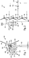
- Fig.1 shows a wind turbine 100 with a tower 102 and a nacelle 104.
- a rotor 106 with three rotor blades 108 and a spinner 110 is arranged on the nacelle 104.
- FIG. During operation, the rotor 106 is rotated by the wind and thereby drives a generator in the nacelle 104 .
- Fig.2 shows a wind farm 112 with, for example, three wind turbines 100, which can be the same or different.
- the three wind turbines 100 are therefore representative of basically any number of wind turbines in a wind farm 112.
- the wind energy installations 100 provide their power, namely in particular the electricity generated, via an electrical park network 114 .
- the currents or powers generated by the individual wind turbines 100 are added up and a transformer 116 is usually provided, which steps up the voltage in the park in order to then feed it into the supply grid 120 at the feed point 118, which is also generally referred to as PCC.
- Fig.2 12 is just a simplified representation of a wind farm 112 with a controller.
- the park network 114 can also be designed differently, for example, in that a transformer is also present at the output of each wind energy installation 100, just to name another exemplary embodiment.
- a wind turbine Fig.1 or any wind turbine of the wind farm according to Fig.2 , or the wind farm according to Fig.2 is presently equipped with a device 200 for controlling and/or regulating (control and regulating device 200) as part of an operational management with controllers 220.
- controllers 220 control an actuating device 300 with corresponding actuators or actuators 301, 302, 303 for, for example, rotor blades, generator and nacelle of wind turbine 100.
- the control and regulation device 200 receives according to Fig.1 and Fig.2 Measurement information from a sensor system 230 via a signal line 231, which goes to a measurement module 210 of the control and regulation device 200.
- This measurement module 210 has a first determination unit 211 for determining a density and a second determination unit 212 for determining the rotational speed n of a rotor of the wind energy installation.
- a pilot control unit 221- e.g. a computing unit or the like with one or more stored operating characteristics R(n', n*) - provided, which is capable of an adjusted speed n' corresponding to a density-adapted operating characteristics R(n') and/or a further corrected one specify speed n*; here also an operating characteristic R(n*) corresponding to a calculated sound pressure S.
- the speed n', n* adapted and/or corrected in this way that is, a speed n' adapted according to the pilot control unit 221, which is additionally or alternatively (preferably additionally) corrected according to a sound pressure S and/or a density-adapted power P to a speed n* -- can be given via a further signal line 232 to the wind turbine 100 and the corresponding control device 300 of the same.
- the speed n* can be further adjusted in such a way that the power is optimized considering the density matched power and the sound pressure S.
- the wind turbine is then operated at a speed greater than the target speed n_soll. Due to the higher speed, an increased value of an AEP (annual energy production) is ultimately to be expected.
- a wind turbine is designed according to a predetermined temperature envelope according to the IEC (International Engineering Code).
- the speed n_norm refers to the speed according to the operating characteristic (BKL).
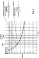
- Fig.3 shows a contour plot K relating to a speed n_quer standardized to the nominal speed n_nenn in relation to a density p_quer normalized to the standard density p_norm.
- the standardized density p_quer can be seen on the x-axis and the standardized speed n_quer on the y-axis, both normalized to reference values n_nenn or p_norm.
- the contour corresponds to the deviation from the guaranteed sound pressure S (here, for example, a relevant value for sound pressure level SPL or sound power level).
- speeds n>n_nom can be driven - namely along the 0 dB contour; ie the adjusted speed is corrected and the system is operated using the corrected speed at a corrected sound emission limit (according to the specifications for sound pressure S, for example using an assigned sound pressure level SPL).
- the system would -if necessary. regulated solely in relation to the sound pressure S or in combination with relation to the power P-- ie with regard to the noise emission to be expected.
- the sound power level or sound pressure level SPL is determined approximately, e.g. by simultaneously recording density ⁇ and speed n.
- the influence of the temperature T on the speed of sound c 0 is also taken into account in this particularly preferred embodiment. Because an increased speed of sound to a leads to a lower Mach number, a further, small reduction in the sound pressure level SPL can be expected. The reduced expected sound pressure S can be used to adjust the nominal speed. This would increase the sound pressure again. However, under simplified assumptions, it can be estimated that the increase in sound pressure S due to increased speed is less than the reduction due to lower density.
- a subscript n refers to the adjusted environment variables and ref to the sizes according to standard atmosphere.
- A represents the area flowing through, ⁇ the generator efficiency and c p the power coefficient.
- the power therefore decreases linearly with the air density.
- the sound pressure S should therefore be lower than under standard conditions.
- ⁇ norm is the normal density for which the operating characteristic was originally designed and n_ corr is the corrected speed n' compared to the speed n originally defined in the operating characteristic.
- the sound pressure (in the formula p') depends on density and Mach number or blade tip speed.
- p ′ const . ⁇ ⁇ ⁇ standard v hint v hint , standard 2.5
- Equation (12) an even slightly higher speed n* could be used compared to Equation (10).
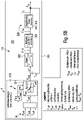
- FIG. 5A is a method for operating a wind energy plant with a rotor and a generator driven via the rotor for generating electrical power according to FIG Fig.1 or Fig.2 exemplified as part of a scheme explained for one Operation under full load.
- Full-load operation relates to operation of the wind energy plant essentially from the nominal wind speed.
- the rated power can usually be reached when the wind speed has reached the rated wind speed.
- a modified pilot control I is implemented for the method by means of a measuring module 210 .
- an environmental variable M relevant to the wind power plant is determined, including at least one air density relevant to the wind power plant.
- the density p_air is determined by simultaneously measuring air pressure p_air, temperature T air and, if necessary, the relative humidity ⁇ _ air.
- the recorded value is used directly for pre-control and/or regulation of the system speed n; namely about the in Figure 5A illustrated pilot control unit 221 - for example with a computing unit or the like with stored operating characteristics R(n', n*).
- the measured values are filtered with a moving average or the like (not shown).
- the system control is adjusted accordingly.
- a rotational speed n of the rotor is determined as system values A as n_ACTUAL and an electrical power P_SOLL to be delivered and a sound pressure S or, if applicable, a power limitation Lp_max of the generator are specified.
- the wind energy installation in particular the generator, namely here an excitation current of the generator, is specified for generating the power to be delivered according to an operational management which specifies a relationship between the rotational speed of the rotor and the electrical power to be delivered - here this includes the operating characteristic R(n', n*) or the in Fig.3 described contour K as part of a pilot control I, which is assigned to the measuring module 210.
- the operational management is adjusted depending on the air density p_air relevant to the wind turbine.
- optimal aerodynamic inflow conditions on the rotor can preferably be achieved, taking into account the current air density p_air and ensuring the predicted yield while taking into account the maximum noise emission.
- both a total guaranteed power P (based on the electrical power to be delivered - P_SOLL in part-load operation or rated power in full-load operation) as well as an upper Sound pressure S must be maintained (e.g. based on the specified sound pressure S or, if necessary, a power limit Lp_max of the generator).
- an adapted rotational speed n′, n* of the rotor of the wind turbine for generating electrical power to be delivered is calculated using the adapted operating management comprising the adapted operating characteristic R(n′, n*) or the in Fig.3 described contour K specified from the pilot control I, ie specified using the air density relevant for the wind turbine.
- this is used to generate an optimized electrical power P to be delivered by means of the controller 220, the adjusted speed n′, n* regularly being a speed n′, n* that is increased compared to the normal speed n (assuming normal air density) with a lower air density .
- the decisive background is that with a significantly lower air density p due to site-specific parameters (elevation of the site, level of the temperature), the expected sound pressure S and thus the essentially relevant sound emission of the wind turbine decreases.
- a correction of the noise emission to be expected is possible according to the specification of a noise pressure level SPL according to the above formula (3) and this noise emission to be expected can also be included in the operational management, for example as in Figure 5A or Figure 5B entered as an adjusted operating characteristic R(n, n*).
- a noise emission of the wind turbine for the specified speed n or already density-adapted speed n 'of the rotor using the air density relevant for the wind turbine can be determined.
- a given speed n can be corrected to n* but additionally the already density-adapted speed n' can also be corrected to n* - namely on the basis of the air density p and sound pressure S relevant for the wind turbine for the determined sound emission S.
- the aim of the regulation is generally a substantially constant speed during full-load operation, at least a speed within an appropriate range.
- the controlled system is fundamentally further developed with the control circuit II with a control device 300 and corresponding actuators or control elements 301, 302, 303 - the order of which is only an example here.
- this controlled system can regulate, for example, a blade angle ⁇ -rot of the rotor blades, an excitation current I_E of the generator and/or an azimuth angle of the nacelle or rotor of the wind turbine (not shown), such as this, for example, based on Fig.1 and Fig.2 and for part-load operation in Figure 5B is explained in detail.
- the result is an increased speed n_IST for full-load operation, which corresponds to the target value of a density-adjusted power P and/or a density-adjusted sound pressure S, ie the adjusted speed n′ and/or corrected speed n*.
- Figure 5B is a method for operating a wind energy plant with a rotor and a generator driven via the rotor for generating electrical power according to FIG Fig.1 or Fig.2 explained by way of example within the framework of a regulation with the control circuit III for operation under partial load.
- the output power is set as a function of the wind, ie as a function of the wind speed.
- Part-load operation is therefore operation in which the wind energy installation cannot yet reach its maximum output power due to the wind being too weak, namely in which it in particular cannot yet reach its nominal power.
- the rated power can be reached when the wind speed has reached the rated wind speed.
- the partial-load operation also relates to operation of the wind energy installation up to the nominal wind speed.
- the wind turbine can be set to generate the output power P_Soll by setting the generator, namely in particular by setting an excitation current I_E, preferably the generator rotor, preferably also taking into account a specification for the sound pressure S. It can also additionally or alternatively a blade angle one or more rotor blades can be adjusted by means of actuator 302. This can be implemented, for example, with a corresponding pitch drive or with a drive for an adjustment angle of one or more flow elements on a rotor blade in actuator 302. An azimuth position of the nacelle of the wind turbine can also be set using actuator 303.
- an increased speed can also be assumed for part-load operation and/or an increased speed n_ACTUAL can be set for control circuit III - this would then correspond to the target value of a density-adapted power P and/or a density-adapted sound pressure P, ie at the adapted speed n' and/or corrected speed n*.
- the wind energy installation is thus adjusted to generate the power to be delivered in accordance with control circuit III under setting an excitation current I_E of the generator and/or a blade angle ⁇ -Rot of a rotor blade and/or an azimuth angle of the nacelle to compare an actual power P_Ist with a target power P_Soll according to a power difference ⁇ P, as is exemplified in Figure 5B is shown.
Claims (17)
- Procédé d'exploitation d'une installation éolienne comprenant un rotor et comprenant un générateur entraîné par l'intermédiaire du rotor pour générer une puissance électrique, comprenant les étapes suivantes :- la détermination d'une variable environnementale pertinente pour l'installation éolienne, comprenant au moins une densité de l'air pertinente pour l'installation éolienne,- la détermination d'une vitesse de rotation du rotor,- la prédéfinition d'une puissance électrique du générateur à fournir,- le réglage de l'installation éolienne pour générer la puissance à fournir conformément à un guide d'exploitation qui indique une relation entre la vitesse de rotation du rotor et la puissance électrique à fournir,- le guide d'exploitation étant adapté en fonction de la densité de l'air pertinente pour l'installation éolienne,caractérisé en ce que- (I) une vitesse de rotation adaptée du rotor de l'installation éolienne pour générer une puissance électrique à fournir est prédéfinie en utilisant le guide d'exploitation adapté et donc en utilisant la densité de l'air pertinente pour l'installation éolienne, la vitesse de rotation adaptée étant une vitesse de rotation augmentée à une densité de l'air réduite pour générer une puissance électrique à fournir optimisée, en outre- (II) une émission sonore de l'installation éolienne est déterminée pour la vitesse de rotation adaptée du rotor en utilisant la densité de l'air pertinente pour l'installation éolienne, et- la vitesse de rotation adaptée est corrigée sur la base de l'émission sonore déterminée en utilisant la densité de l'air pertinente pour l'installation éolienne.
- Procédé selon la revendication 1, caractérisé en ce que la densité de l'air en tant que variable environnementale pertinente est une densité de l'air réduite par rapport à une densité standard d'une atmosphère standard et le guide d'exploitation est adapté en fonction de la densité de l'air réduite pour l'installation éolienne.
- Procédé selon la revendication 1 ou 2, caractérisé en ce que- la vitesse de rotation corrigée sur la base de l'émission sonore déterminée en utilisant la densité de l'air pertinente pour l'installation éolienne est encore davantage augmentée par rapport à la vitesse de rotation adaptée, ou- la vitesse de rotation corrigée n'est pas encore davantage augmentée par rapport à la vitesse de rotation adaptée et l'installation éolienne est exploitée avec une émission sonore encore plus faible ou inchangée.
- Procédé selon l'une quelconque des revendications 1 à 3, caractérisé en ce que la vitesse de rotation adaptée est limitée sur la base de l'émission sonore déterminée en utilisant la densité de l'air pertinente pour l'installation éolienne.
- Procédé selon l'une quelconque des revendications précédentes, caractérisé en ce que- le guide d'exploitation comprend une courbe caractéristique d'exploitation vitesse de rotation-puissance (courbe caractéristique d'exploitation n/P),- une courbe caractéristique d'exploitation adaptée étant prédéfinie en fonction de la densité de l'air pertinente pour l'installation éolienne et l'installation éolienne étant réglée pour générer la puissance à fournir sur la base de la courbe caractéristique d'exploitation vitesse de rotation-puissance adaptée dans le guide d'exploitation,- une vitesse de rotation actuelle ainsi prédéfinie et adaptée étant prédéfinie dans le guide d'exploitation et étant ensuite réglée au moyen d'une commande et/ou d'une régulation.
- Procédé selon l'une quelconque des revendications précédentes, caractérisé en ce que le réglage de l'installation éolienne est effectué au moyen d'un réglage du générateur en réglant un courant d'excitation du générateur.
- Procédé selon l'une quelconque des revendications précédentes, caractérisé en ce que la densité de l'air est une densité de l'air actuelle à l'emplacement de l'installation éolienne, qui est mesurée en permanence et adaptée dynamiquement et/ou une densité de l'air qui règne généralement à l'emplacement de l'installation éolienne, qui est mesurée une fois ou de manière répétée et adaptée statiquement.
- Procédé selon l'une quelconque des revendications précédentes, caractérisé en ce que- la densité de l'air est déterminée à partir de valeurs ambiantes mesurées, les valeurs ambiantes comprenant une température de l'air pertinente pour l'installation éolienne, et/ou- la densité de l'air est déterminée à partir de valeurs ambiantes mesurées, les valeurs ambiantes comprenant éventuellement la pression de l'air et l'humidité de l'air relative ou absolue.
- Procédé selon l'une quelconque des revendications précédentes, caractérisé en ce que- une émission sonore normale de l'installation éolienne dans une atmosphère standard est déterminée pour la vitesse de rotation du rotor, et- l'émission sonore normale est comparée à l'émission sonore de l'installation éolienne pour la vitesse de rotation adaptée du rotor en utilisant la densité de l'air et/ou la température de l'air pertinentes pour l'installation éolienne, et- la vitesse de rotation adaptée du rotor de l'installation éolienne est corrigée et éventuellement limitée sur la base de l'émission sonore.
- Procédé selon l'une quelconque des revendications précédentes, caractérisé en ce que- l'installation éolienne est exploitée au moyen de la vitesse de rotation corrigée pour l'émission sonore corrigée, de telle sorte que l'installation éolienne est exploitée à une limite d'émission sonore corrigée.
- Procédé selon l'une quelconque des revendications précédentes, caractérisé en ce que- tout d'abord, la vitesse de rotation du rotor est réglée en tenant compte d'une densité standard prédéterminée d'une atmosphère standard, et- ensuite, la vitesse de rotation adaptée est prédéfinie en tenant compte de la densité de l'air et/ou de la température de l'air pertinentes pour l'installation éolienne,- la vitesse de rotation adaptée est corrigée et l'installation est exploitée au moyen de la vitesse de rotation corrigée à la limite d'émission sonore corrigée.
- Procédé selon la revendication 10 ou 11, caractérisé en ce que la densité de l'air est une densité de l'air réduite par rapport à une densité standard et la vitesse de rotation corrigée est d'une part une vitesse de rotation augmentée par rapport à la vitesse de rotation pour l'atmosphère standard et d'autre part une vitesse davantage augmentée et/ou limitée par rapport à la vitesse de rotation adaptée, éventuellement en fonction de la température de l'air.
- Procédé selon l'une quelconque des revendications 1 à 12, caractérisé en ce que l'installation éolienne est réglée pour générer la puissance à fournir en prédéfinissant la vitesse de rotation adaptée (n') et la vitesse de rotation adaptée et corrigée (n*) ainsi que,- en mode d'exploitation à pleine charge, en régulant la vitesse de rotation.
- Procédé selon l'une quelconque des revendications 1 à 12, caractérisé en ce que l'installation éolienne est réglée pour générer la puissance à fournir en prédéfinissant la vitesse de rotation adaptée (n') et la vitesse de rotation adaptée et corrigée (n*) ainsi que,- en mode d'exploitation à charge partielle, en réglant le générateur en réglant un courant d'excitation, une ou plusieurs pales de rotor et/ou un ou plusieurs éléments d'écoulement sur une pale de rotor, du rotor,- et/ou en réglant un angle d'azimut pour la nacelle de l'installation éolienne,- en prédéfinissant la puissance électrique à fournir, la densité de l'air et l'émission sonore en mode d'exploitation à charge partielle, la vitesse de rotation étant influencée et/ou réglée au moyen d'une commande d'un angle d'inclinaison d'un composant sur le rotor, d'un angle de pas d'une pale de rotor et/ou d'un angle d'inclinaison et/ou d'un ou plusieurs éléments d'écoulement sur une pale de rotor.
- Appareil de commande et/ou de régulation d'une installation éolienne comprenant un guide d'exploitation configuré pour l'exécution du procédé selon l'une quelconque des revendications précédentes, le guide d'exploitation comprenant une courbe caractéristique d'exploitation vitesse de rotation-puissance (courbe caractéristique d'exploitation n/P), la courbe caractéristique d'exploitation adaptée étant établie et prédéfinie dans le guide d'exploitation en fonction de la densité de l'air pertinente pour l'installation éolienne et l'installation éolienne pour générer la puissance à fournir est ajustable dans la gestion de l'exploitation au moyen de la courbe caractéristique d'exploitation vitesse de rotation-puissance adaptée.
- Installation éolienne (100) comprenant un rotor et un générateur entraîné par l'intermédiaire du rotor pour générer une puissance électrique et comprenant un appareil de commande et/ou de régulation selon la revendication 15.
- Parc éolien (112) comprenant une pluralité d'installations éoliennes (100) qui sont raccordées à un réseau d'alimentation (120) par l'intermédiaire d'un point d'injection commun (118) pour injecter la puissance générée par la pluralité d'installations éoliennes, et dans lequel au moins une des installations éoliennes est une installation éolienne selon la revendication 16.
Applications Claiming Priority (2)
| Application Number | Priority Date | Filing Date | Title |
|---|---|---|---|
| DE102016124703.0A DE102016124703A1 (de) | 2016-12-16 | 2016-12-16 | Verfahren zum Betrieb einer Windenergieanlage sowie Einrichtung zum Steuern und/oder Regeln einer Windenergieanlage und entsprechende Windenergieanlage mit einem Rotor und einem über den Rotor angetriebenen Generator zur Erzeugung einer elektrischen Leistung |
| PCT/EP2017/082869 WO2018109100A1 (fr) | 2016-12-16 | 2017-12-14 | Procédé pour faire fonctionner un aérogénérateur ainsi que dispositif pour commander et/ou réguler un aérogénérateur et aérogénérateur correspondant comprenant un rotor et un générateur entraîné par le biais du rotor pour générer une puissance électrique |
Publications (2)
| Publication Number | Publication Date |
|---|---|
| EP3555461A1 EP3555461A1 (fr) | 2019-10-23 |
| EP3555461B1 true EP3555461B1 (fr) | 2022-11-30 |
Family
ID=60857061
Family Applications (1)
| Application Number | Title | Priority Date | Filing Date |
|---|---|---|---|
| EP17822240.2A Active EP3555461B1 (fr) | 2016-12-16 | 2017-12-14 | Procédé pour faire fonctionner un aérogénérateur ainsi que dispositif pour commander et/ou réguler un aérogénérateur et aérogénérateur correspondant comprenant un rotor et un générateur entraîné par le biais du rotor pour générer une puissance électrique |
Country Status (9)
| Country | Link |
|---|---|
| US (1) | US20200102934A1 (fr) |
| EP (1) | EP3555461B1 (fr) |
| JP (1) | JP6909292B2 (fr) |
| KR (1) | KR20190095402A (fr) |
| CN (1) | CN110139980B (fr) |
| BR (1) | BR112019012016A2 (fr) |
| CA (1) | CA3044752A1 (fr) |
| DE (1) | DE102016124703A1 (fr) |
| WO (1) | WO2018109100A1 (fr) |
Families Citing this family (4)
| Publication number | Priority date | Publication date | Assignee | Title |
|---|---|---|---|---|
| DE102018124084A1 (de) | 2018-09-28 | 2020-04-02 | Wobben Properties Gmbh | Verfahren zum Betreiben einer Windenergieanlage, Windenergieanlage und Windpark |
| DE102019106073A1 (de) * | 2019-03-11 | 2020-09-17 | Wobben Properties Gmbh | Verfahren zum Erkennen eines Eisansatzes an einer Windenergieanlage |
| CN110925134B (zh) * | 2019-12-03 | 2021-06-18 | 上海明华电力科技有限公司 | 一种风电机组的输出功率给定值实时修正系统及方法 |
| EP3995691A1 (fr) * | 2020-11-04 | 2022-05-11 | Wobben Properties GmbH | Procédé de fonctionnement d'une éolienne, éolienne et parc éolien |
Family Cites Families (15)
| Publication number | Priority date | Publication date | Assignee | Title |
|---|---|---|---|---|
| DE19844258A1 (de) | 1998-09-26 | 2000-03-30 | Dewind Technik Gmbh | Windenergieanlage |
| DE10109553B4 (de) | 2001-02-28 | 2006-03-30 | Wobben, Aloys, Dipl.-Ing. | Luftdichteabhängige Leistungsregelung |
| JP2005240725A (ja) * | 2004-02-27 | 2005-09-08 | Mitsubishi Heavy Ind Ltd | 風力発電装置およびその発電出力制御方法 |
| JP3764469B1 (ja) | 2005-02-17 | 2006-04-05 | 正秀 木村 | 風の計測制御装置及び計測制御方法 |
| US20080112807A1 (en) | 2006-10-23 | 2008-05-15 | Ulrich Uphues | Methods and apparatus for operating a wind turbine |
| US7883317B2 (en) * | 2007-02-02 | 2011-02-08 | General Electric Company | Method for optimizing the operation of a wind turbine |
| US8093737B2 (en) * | 2008-05-29 | 2012-01-10 | General Electric Company | Method for increasing energy capture in a wind turbine |
| JP5107271B2 (ja) * | 2009-01-06 | 2012-12-26 | 三菱重工業株式会社 | 風力発電装置及びそのブレードピッチ角制御方法並びにプログラム |
| DE102009025445B3 (de) | 2009-06-18 | 2010-09-23 | Nordex Energy Gmbh | Verfahren zum Betreiben einer Windenergieanlage und Windenergieanlage zur Ausführung des Verfahrens |
| DE102010054014A1 (de) * | 2010-12-10 | 2012-06-14 | Nordex Energy Gmbh | Verfahren zum Betrieb einer pitchgeregelten Windenergieanlage |
| WO2012149984A1 (fr) * | 2011-05-04 | 2012-11-08 | Siemens Aktiengesellschaft | Système et procédé pour faire fonctionner une éolienne au moyen d'une référence de vitesse adaptative |
| US9404478B2 (en) * | 2012-04-24 | 2016-08-02 | General Electric Company | Methods and systems for operating a wind turbine in noise reduced operation modes |
| CN202746093U (zh) * | 2012-06-26 | 2013-02-20 | 华锐风电科技(集团)股份有限公司 | 风力发电机组的噪声控制设备 |
| WO2014078770A1 (fr) * | 2012-11-19 | 2014-05-22 | Elwha Llc | Atténuation de génération de bruit de pale de turbine éolienne |
| CN104747366A (zh) * | 2013-12-26 | 2015-07-01 | 上海电气风电设备有限公司 | 一种自适应空气密度变化的风电发电机组控制方法 |
-
2016
- 2016-12-16 DE DE102016124703.0A patent/DE102016124703A1/de not_active Withdrawn
-
2017
- 2017-12-14 BR BR112019012016-5A patent/BR112019012016A2/pt not_active Application Discontinuation
- 2017-12-14 CN CN201780078098.4A patent/CN110139980B/zh active Active
- 2017-12-14 EP EP17822240.2A patent/EP3555461B1/fr active Active
- 2017-12-14 KR KR1020197020717A patent/KR20190095402A/ko not_active Application Discontinuation
- 2017-12-14 JP JP2019529252A patent/JP6909292B2/ja active Active
- 2017-12-14 US US16/469,997 patent/US20200102934A1/en not_active Abandoned
- 2017-12-14 WO PCT/EP2017/082869 patent/WO2018109100A1/fr unknown
- 2017-12-14 CA CA3044752A patent/CA3044752A1/fr not_active Abandoned
Also Published As
| Publication number | Publication date |
|---|---|
| KR20190095402A (ko) | 2019-08-14 |
| DE102016124703A1 (de) | 2018-06-21 |
| JP6909292B2 (ja) | 2021-07-28 |
| JP2020501489A (ja) | 2020-01-16 |
| WO2018109100A1 (fr) | 2018-06-21 |
| CN110139980B (zh) | 2021-12-10 |
| BR112019012016A2 (pt) | 2019-10-29 |
| CN110139980A (zh) | 2019-08-16 |
| CA3044752A1 (fr) | 2018-06-21 |
| EP3555461A1 (fr) | 2019-10-23 |
| US20200102934A1 (en) | 2020-04-02 |
Similar Documents
| Publication | Publication Date | Title |
|---|---|---|
| EP2463520B1 (fr) | Procédé de fonctionnement d'une éolienne avec réglage de l'angle d'incidence de pale | |
| EP3555461B1 (fr) | Procédé pour faire fonctionner un aérogénérateur ainsi que dispositif pour commander et/ou réguler un aérogénérateur et aérogénérateur correspondant comprenant un rotor et un générateur entraîné par le biais du rotor pour générer une puissance électrique | |
| EP2463518B1 (fr) | Procédé de fonctionnement d'une éolienne avec contrôle du pas | |
| EP1792075B1 (fr) | Procede de regulation d'une installation d'energie eolienne, et installation d'energie eolienne correspondante | |
| EP2556247B1 (fr) | Régulation d'inertie dynamique | |
| EP3548737B1 (fr) | Éolienne et procédé permettant de faire fonctionner une éolienne | |
| DE102010017777A1 (de) | Verfahren und Vorrichtung zum Steuern der Umfangsgeschwindigkeit an Rotorflügelspitzen | |
| EP3420226B1 (fr) | Procédé pour déterminer une vitesse du vent équivalente | |
| EP3931438B1 (fr) | Procédé servant à faire fonctionner une éolienne, structure de régulation, éolienne et parc éolien | |
| DE102010041508A1 (de) | Drehzahlanpassung einer Windenergieanlage | |
| EP3803109A1 (fr) | Procédé pour faire fonctionner une éolienne | |
| WO2019134793A1 (fr) | Fonctionnement d'une éolienne en cas de tempête | |
| WO2019138105A1 (fr) | Éolienne et procédé de commande d'une éolienne | |
| EP3740674A1 (fr) | Procédé de commande d'une éolienne et éolienne | |
| EP3995691A1 (fr) | Procédé de fonctionnement d'une éolienne, éolienne et parc éolien | |
| EP3842633A1 (fr) | Procédé de fonctionnement d'une éolienne, éolienne et parc éolien | |
| EP3848575A1 (fr) | Procédé de fonctionnement d'un parc éolien comprenant plusieurs éoliennes ainsi que parc éolien correspondant | |
| EP3768970B1 (fr) | Procédé pour faire fonctionner une éolienne, éolienne et parc éolien | |
| DE102019115943A1 (de) | Verfahren zum Steuern einer Windenergieanlage | |
| WO2019243129A1 (fr) | Fonctionnement à puissance réduite d'une éolienne | |
| DE102018130636A1 (de) | Verfahren zum Betreiben einer Windenergieanlage | |
| EP4074960A1 (fr) | Procédé de fonctionnement d'une ferme éolienne et ferme éolienne | |
| EP4092264A1 (fr) | Procédé de commande d'une éolienne, éolienne et parc éolien | |
| EP4297230A2 (fr) | Générateurs basés sur un convertisseur et procédé d'alimentation en puissance électrique | |
| DE102018116299A1 (de) | Verfahren zum Einspeisen elektrischer Leistung in ein elektrisches Versorgungsnetz |
Legal Events
| Date | Code | Title | Description |
|---|---|---|---|
| STAA | Information on the status of an ep patent application or granted ep patent |
Free format text: STATUS: UNKNOWN |
|
| STAA | Information on the status of an ep patent application or granted ep patent |
Free format text: STATUS: THE INTERNATIONAL PUBLICATION HAS BEEN MADE |
|
| PUAI | Public reference made under article 153(3) epc to a published international application that has entered the european phase |
Free format text: ORIGINAL CODE: 0009012 |
|
| STAA | Information on the status of an ep patent application or granted ep patent |
Free format text: STATUS: REQUEST FOR EXAMINATION WAS MADE |
|
| 17P | Request for examination filed |
Effective date: 20190716 |
|
| AK | Designated contracting states |
Kind code of ref document: A1 Designated state(s): AL AT BE BG CH CY CZ DE DK EE ES FI FR GB GR HR HU IE IS IT LI LT LU LV MC MK MT NL NO PL PT RO RS SE SI SK SM TR |
|
| GRAP | Despatch of communication of intention to grant a patent |
Free format text: ORIGINAL CODE: EPIDOSNIGR1 |
|
| STAA | Information on the status of an ep patent application or granted ep patent |
Free format text: STATUS: GRANT OF PATENT IS INTENDED |
|
| INTG | Intention to grant announced |
Effective date: 20220509 |
|
| GRAJ | Information related to disapproval of communication of intention to grant by the applicant or resumption of examination proceedings by the epo deleted |
Free format text: ORIGINAL CODE: EPIDOSDIGR1 |
|
| STAA | Information on the status of an ep patent application or granted ep patent |
Free format text: STATUS: REQUEST FOR EXAMINATION WAS MADE |
|
| INTC | Intention to grant announced (deleted) | ||
| GRAP | Despatch of communication of intention to grant a patent |
Free format text: ORIGINAL CODE: EPIDOSNIGR1 |
|
| STAA | Information on the status of an ep patent application or granted ep patent |
Free format text: STATUS: GRANT OF PATENT IS INTENDED |
|
| GRAS | Grant fee paid |
Free format text: ORIGINAL CODE: EPIDOSNIGR3 |
|
| INTG | Intention to grant announced |
Effective date: 20220928 |
|
| GRAA | (expected) grant |
Free format text: ORIGINAL CODE: 0009210 |
|
| STAA | Information on the status of an ep patent application or granted ep patent |
Free format text: STATUS: THE PATENT HAS BEEN GRANTED |
|
| AK | Designated contracting states |
Kind code of ref document: B1 Designated state(s): AL AT BE BG CH CY CZ DE DK EE ES FI FR GB GR HR HU IE IS IT LI LT LU LV MC MK MT NL NO PL PT RO RS SE SI SK SM TR |
|
| REG | Reference to a national code |
Ref country code: CH Ref legal event code: EP Ref country code: GB Ref legal event code: FG4D Free format text: NOT ENGLISH |
|
| REG | Reference to a national code |
Ref country code: AT Ref legal event code: REF Ref document number: 1534879 Country of ref document: AT Kind code of ref document: T Effective date: 20221215 Ref country code: DE Ref legal event code: R096 Ref document number: 502017014181 Country of ref document: DE |
|
| REG | Reference to a national code |
Ref country code: IE Ref legal event code: FG4D Free format text: LANGUAGE OF EP DOCUMENT: GERMAN |
|
| REG | Reference to a national code |
Ref country code: LT Ref legal event code: MG9D |
|
| REG | Reference to a national code |
Ref country code: NL Ref legal event code: MP Effective date: 20221130 |
|
| PG25 | Lapsed in a contracting state [announced via postgrant information from national office to epo] |
Ref country code: SE Free format text: LAPSE BECAUSE OF FAILURE TO SUBMIT A TRANSLATION OF THE DESCRIPTION OR TO PAY THE FEE WITHIN THE PRESCRIBED TIME-LIMIT Effective date: 20221130 Ref country code: PT Free format text: LAPSE BECAUSE OF FAILURE TO SUBMIT A TRANSLATION OF THE DESCRIPTION OR TO PAY THE FEE WITHIN THE PRESCRIBED TIME-LIMIT Effective date: 20230331 Ref country code: NO Free format text: LAPSE BECAUSE OF FAILURE TO SUBMIT A TRANSLATION OF THE DESCRIPTION OR TO PAY THE FEE WITHIN THE PRESCRIBED TIME-LIMIT Effective date: 20230228 Ref country code: LT Free format text: LAPSE BECAUSE OF FAILURE TO SUBMIT A TRANSLATION OF THE DESCRIPTION OR TO PAY THE FEE WITHIN THE PRESCRIBED TIME-LIMIT Effective date: 20221130 Ref country code: FI Free format text: LAPSE BECAUSE OF FAILURE TO SUBMIT A TRANSLATION OF THE DESCRIPTION OR TO PAY THE FEE WITHIN THE PRESCRIBED TIME-LIMIT Effective date: 20221130 Ref country code: ES Free format text: LAPSE BECAUSE OF FAILURE TO SUBMIT A TRANSLATION OF THE DESCRIPTION OR TO PAY THE FEE WITHIN THE PRESCRIBED TIME-LIMIT Effective date: 20221130 |
|
| PG25 | Lapsed in a contracting state [announced via postgrant information from national office to epo] |
Ref country code: RS Free format text: LAPSE BECAUSE OF FAILURE TO SUBMIT A TRANSLATION OF THE DESCRIPTION OR TO PAY THE FEE WITHIN THE PRESCRIBED TIME-LIMIT Effective date: 20221130 Ref country code: PL Free format text: LAPSE BECAUSE OF FAILURE TO SUBMIT A TRANSLATION OF THE DESCRIPTION OR TO PAY THE FEE WITHIN THE PRESCRIBED TIME-LIMIT Effective date: 20221130 Ref country code: LV Free format text: LAPSE BECAUSE OF FAILURE TO SUBMIT A TRANSLATION OF THE DESCRIPTION OR TO PAY THE FEE WITHIN THE PRESCRIBED TIME-LIMIT Effective date: 20221130 Ref country code: IS Free format text: LAPSE BECAUSE OF FAILURE TO SUBMIT A TRANSLATION OF THE DESCRIPTION OR TO PAY THE FEE WITHIN THE PRESCRIBED TIME-LIMIT Effective date: 20230330 Ref country code: HR Free format text: LAPSE BECAUSE OF FAILURE TO SUBMIT A TRANSLATION OF THE DESCRIPTION OR TO PAY THE FEE WITHIN THE PRESCRIBED TIME-LIMIT Effective date: 20221130 Ref country code: GR Free format text: LAPSE BECAUSE OF FAILURE TO SUBMIT A TRANSLATION OF THE DESCRIPTION OR TO PAY THE FEE WITHIN THE PRESCRIBED TIME-LIMIT Effective date: 20230301 |
|
| PGFP | Annual fee paid to national office [announced via postgrant information from national office to epo] |
Ref country code: DE Payment date: 20230117 Year of fee payment: 6 |
|
| PG25 | Lapsed in a contracting state [announced via postgrant information from national office to epo] |
Ref country code: NL Free format text: LAPSE BECAUSE OF FAILURE TO SUBMIT A TRANSLATION OF THE DESCRIPTION OR TO PAY THE FEE WITHIN THE PRESCRIBED TIME-LIMIT Effective date: 20221130 |
|
| PG25 | Lapsed in a contracting state [announced via postgrant information from national office to epo] |
Ref country code: SM Free format text: LAPSE BECAUSE OF FAILURE TO SUBMIT A TRANSLATION OF THE DESCRIPTION OR TO PAY THE FEE WITHIN THE PRESCRIBED TIME-LIMIT Effective date: 20221130 Ref country code: RO Free format text: LAPSE BECAUSE OF FAILURE TO SUBMIT A TRANSLATION OF THE DESCRIPTION OR TO PAY THE FEE WITHIN THE PRESCRIBED TIME-LIMIT Effective date: 20221130 Ref country code: EE Free format text: LAPSE BECAUSE OF FAILURE TO SUBMIT A TRANSLATION OF THE DESCRIPTION OR TO PAY THE FEE WITHIN THE PRESCRIBED TIME-LIMIT Effective date: 20221130 Ref country code: DK Free format text: LAPSE BECAUSE OF FAILURE TO SUBMIT A TRANSLATION OF THE DESCRIPTION OR TO PAY THE FEE WITHIN THE PRESCRIBED TIME-LIMIT Effective date: 20221130 Ref country code: CZ Free format text: LAPSE BECAUSE OF FAILURE TO SUBMIT A TRANSLATION OF THE DESCRIPTION OR TO PAY THE FEE WITHIN THE PRESCRIBED TIME-LIMIT Effective date: 20221130 |
|
| REG | Reference to a national code |
Ref country code: CH Ref legal event code: PL |
|
| REG | Reference to a national code |
Ref country code: BE Ref legal event code: MM Effective date: 20221231 |
|
| PG25 | Lapsed in a contracting state [announced via postgrant information from national office to epo] |
Ref country code: SK Free format text: LAPSE BECAUSE OF FAILURE TO SUBMIT A TRANSLATION OF THE DESCRIPTION OR TO PAY THE FEE WITHIN THE PRESCRIBED TIME-LIMIT Effective date: 20221130 Ref country code: LU Free format text: LAPSE BECAUSE OF NON-PAYMENT OF DUE FEES Effective date: 20221214 Ref country code: AL Free format text: LAPSE BECAUSE OF FAILURE TO SUBMIT A TRANSLATION OF THE DESCRIPTION OR TO PAY THE FEE WITHIN THE PRESCRIBED TIME-LIMIT Effective date: 20221130 |
|
| REG | Reference to a national code |
Ref country code: DE Ref legal event code: R097 Ref document number: 502017014181 Country of ref document: DE |
|
| PLBE | No opposition filed within time limit |
Free format text: ORIGINAL CODE: 0009261 |
|
| STAA | Information on the status of an ep patent application or granted ep patent |
Free format text: STATUS: NO OPPOSITION FILED WITHIN TIME LIMIT |
|
| PG25 | Lapsed in a contracting state [announced via postgrant information from national office to epo] |
Ref country code: LI Free format text: LAPSE BECAUSE OF NON-PAYMENT OF DUE FEES Effective date: 20221231 Ref country code: IE Free format text: LAPSE BECAUSE OF NON-PAYMENT OF DUE FEES Effective date: 20221214 Ref country code: CH Free format text: LAPSE BECAUSE OF NON-PAYMENT OF DUE FEES Effective date: 20221231 |
|
| 26N | No opposition filed |
Effective date: 20230831 |
|
| PG25 | Lapsed in a contracting state [announced via postgrant information from national office to epo] |
Ref country code: SI Free format text: LAPSE BECAUSE OF FAILURE TO SUBMIT A TRANSLATION OF THE DESCRIPTION OR TO PAY THE FEE WITHIN THE PRESCRIBED TIME-LIMIT Effective date: 20221130 Ref country code: BE Free format text: LAPSE BECAUSE OF NON-PAYMENT OF DUE FEES Effective date: 20221231 |
|
| PGFP | Annual fee paid to national office [announced via postgrant information from national office to epo] |
Ref country code: GB Payment date: 20231220 Year of fee payment: 7 |
|
| PGFP | Annual fee paid to national office [announced via postgrant information from national office to epo] |
Ref country code: FR Payment date: 20231219 Year of fee payment: 7 |
|
| REG | Reference to a national code |
Ref country code: AT Ref legal event code: MM01 Ref document number: 1534879 Country of ref document: AT Kind code of ref document: T Effective date: 20221214 |
|
| PG25 | Lapsed in a contracting state [announced via postgrant information from national office to epo] |
Ref country code: HU Free format text: LAPSE BECAUSE OF FAILURE TO SUBMIT A TRANSLATION OF THE DESCRIPTION OR TO PAY THE FEE WITHIN THE PRESCRIBED TIME-LIMIT; INVALID AB INITIO Effective date: 20171214 |
|
| PG25 | Lapsed in a contracting state [announced via postgrant information from national office to epo] |
Ref country code: AT Free format text: LAPSE BECAUSE OF NON-PAYMENT OF DUE FEES Effective date: 20221214 |
|
| PG25 | Lapsed in a contracting state [announced via postgrant information from national office to epo] |
Ref country code: CY Free format text: LAPSE BECAUSE OF FAILURE TO SUBMIT A TRANSLATION OF THE DESCRIPTION OR TO PAY THE FEE WITHIN THE PRESCRIBED TIME-LIMIT Effective date: 20221130 Ref country code: AT Free format text: LAPSE BECAUSE OF NON-PAYMENT OF DUE FEES Effective date: 20221214 |
|
| PGFP | Annual fee paid to national office [announced via postgrant information from national office to epo] |
Ref country code: DE Payment date: 20240112 Year of fee payment: 7 |