EP3555392B1 - Arrangement for manipulating a vehicle door lock remote control device - Google Patents
Arrangement for manipulating a vehicle door lock remote control device Download PDFInfo
- Publication number
- EP3555392B1 EP3555392B1 EP17832055.2A EP17832055A EP3555392B1 EP 3555392 B1 EP3555392 B1 EP 3555392B1 EP 17832055 A EP17832055 A EP 17832055A EP 3555392 B1 EP3555392 B1 EP 3555392B1
- Authority
- EP
- European Patent Office
- Prior art keywords
- remote control
- arrangement
- control device
- door lock
- lock remote
- Prior art date
- Legal status (The legal status is an assumption and is not a legal conclusion. Google has not performed a legal analysis and makes no representation as to the accuracy of the status listed.)
- Active
Links
Images




Classifications
-
- E—FIXED CONSTRUCTIONS
- E05—LOCKS; KEYS; WINDOW OR DOOR FITTINGS; SAFES
- E05B—LOCKS; ACCESSORIES THEREFOR; HANDCUFFS
- E05B81/00—Power-actuated vehicle locks
-
- E—FIXED CONSTRUCTIONS
- E05—LOCKS; KEYS; WINDOW OR DOOR FITTINGS; SAFES
- E05B—LOCKS; ACCESSORIES THEREFOR; HANDCUFFS
- E05B19/00—Keys; Accessories therefor
- E05B19/0005—Key safes
-
- G—PHYSICS
- G07—CHECKING-DEVICES
- G07C—TIME OR ATTENDANCE REGISTERS; REGISTERING OR INDICATING THE WORKING OF MACHINES; GENERATING RANDOM NUMBERS; VOTING OR LOTTERY APPARATUS; ARRANGEMENTS, SYSTEMS OR APPARATUS FOR CHECKING NOT PROVIDED FOR ELSEWHERE
- G07C9/00—Individual registration on entry or exit
- G07C9/00174—Electronically operated locks; Circuits therefor; Nonmechanical keys therefor, e.g. passive or active electrical keys or other data carriers without mechanical keys
-
- G—PHYSICS
- G07—CHECKING-DEVICES
- G07C—TIME OR ATTENDANCE REGISTERS; REGISTERING OR INDICATING THE WORKING OF MACHINES; GENERATING RANDOM NUMBERS; VOTING OR LOTTERY APPARATUS; ARRANGEMENTS, SYSTEMS OR APPARATUS FOR CHECKING NOT PROVIDED FOR ELSEWHERE
- G07C9/00—Individual registration on entry or exit
- G07C9/00174—Electronically operated locks; Circuits therefor; Nonmechanical keys therefor, e.g. passive or active electrical keys or other data carriers without mechanical keys
- G07C9/00896—Electronically operated locks; Circuits therefor; Nonmechanical keys therefor, e.g. passive or active electrical keys or other data carriers without mechanical keys specially adapted for particular uses
-
- G—PHYSICS
- G07—CHECKING-DEVICES
- G07C—TIME OR ATTENDANCE REGISTERS; REGISTERING OR INDICATING THE WORKING OF MACHINES; GENERATING RANDOM NUMBERS; VOTING OR LOTTERY APPARATUS; ARRANGEMENTS, SYSTEMS OR APPARATUS FOR CHECKING NOT PROVIDED FOR ELSEWHERE
- G07C9/00—Individual registration on entry or exit
- G07C9/00174—Electronically operated locks; Circuits therefor; Nonmechanical keys therefor, e.g. passive or active electrical keys or other data carriers without mechanical keys
- G07C9/00944—Details of construction or manufacture
-
- B—PERFORMING OPERATIONS; TRANSPORTING
- B60—VEHICLES IN GENERAL
- B60R—VEHICLES, VEHICLE FITTINGS, OR VEHICLE PARTS, NOT OTHERWISE PROVIDED FOR
- B60R25/00—Fittings or systems for preventing or indicating unauthorised use or theft of vehicles
- B60R25/01—Fittings or systems for preventing or indicating unauthorised use or theft of vehicles operating on vehicle systems or fittings, e.g. on doors, seats or windscreens
-
- E—FIXED CONSTRUCTIONS
- E05—LOCKS; KEYS; WINDOW OR DOOR FITTINGS; SAFES
- E05B—LOCKS; ACCESSORIES THEREFOR; HANDCUFFS
- E05B19/00—Keys; Accessories therefor
- E05B19/0082—Keys or shanks being removably stored in a larger object, e.g. a remote control or a key fob
-
- E—FIXED CONSTRUCTIONS
- E05—LOCKS; KEYS; WINDOW OR DOOR FITTINGS; SAFES
- E05B—LOCKS; ACCESSORIES THEREFOR; HANDCUFFS
- E05B47/00—Operating or controlling locks or other fastening devices by electric or magnetic means
- E05B2047/0094—Mechanical aspects of remotely controlled locks
- E05B2047/0095—Mechanical aspects of locks controlled by telephone signals, e.g. by mobile phones
-
- G—PHYSICS
- G07—CHECKING-DEVICES
- G07B—TICKET-ISSUING APPARATUS; FARE-REGISTERING APPARATUS; FRANKING APPARATUS
- G07B15/00—Arrangements or apparatus for collecting fares, tolls or entrance fees at one or more control points
Definitions
- the present invention relates to an arrangement for manipulating a vehicle door lock remote control device.
- a vehicle such as a car
- a wireless remote control device allows the doors of the vehicle to be unlocked and locked from a location near the vehicle.
- Such a remote control device may transmit a radio signal that is coded by a code, which is unique to the vehicle. In this way, it is ensured that the operation of the remote control device results in that the doors of the vehicle actually associated with the remote control is unlocked or locked by the manual operation of this particular remote control device.
- This type of remote control device is often designed as a handheld, miniature housing, which accommodates a battery, electronic circuitry including a radio transmitter, and at least one manually operated switch, usually in the form of pushbutton.
- a radio transmitter usually in the form of pushbutton.
- pushbuttons are provided. Pushing the first pushbutton leads to the transmitter transmitting a radio signal coded with an unlocking instruction code. Pushing the second pushbutton leads to the transmitter transmitting a radio signal coded with a locking instruction code.
- the remote control device is combined with, or made as a part of, a physical key which may be used, e.g., to activate an ignition lock and start the engine of the vehicle.
- a physical key which may be used, e.g., to activate an ignition lock and start the engine of the vehicle.
- the handheld housing may serve as a handgrip of the physical key.
- This traditional solution is particularly useful for privately owned vehicles, which are typically driven by only one or a few persons, who bring their own key (with associated remote control device) with them.
- a car share service is usually managed entirely by digital communication, e.g. on the Internet.
- a participant of the service may reserve and be allocated a car merely by using an application on her/his mobile phone. It would be cumbersome if the user then had to obtain a physical key (or remote control device) in order to get access to the allocated vehicle.
- This publication relates to a method and device that involves locking and unlocking a motor vehicle by a door lock that is remotely controlled by an opening signal that is controlled by a serial key.
- the opening signal is wirelessly transmitted to the vehicle by the key.
- the key is kept in a key box that is controlled by an activation unit, which is disposed for unlocking the vehicle by an auxiliary transmitter (operated by radio, infrared, Bluetooth, or mobile communication) to transmit the opening signal and to activate a central locking system in the vehicle.
- the key box includes pressing elements, which may be linear motors or electromagnetic actuators, and which are controlled by the auxiliary transmitter.
- EP-1 808 336 A1 also discloses an access control device for a motor vehicle.
- the device has a vehicle key kept inside the vehicle, in such a way that the key is set in operation by a remote control device from outside the vehicle for locking and unlocking of a door lock.
- the key is movably mounted in a drawer within the vehicle.
- An actuation unit is moved by a linear drive.
- the actuation unit is set in operation by the remote control device for operating the vehicle key, which is provided in the drawer of the vehicle.
- WO2017/168341A1 discloses a safety device for holding and sharing a key provided with a remote control.
- the safety device comprises an actuating device that in use operates a push button in the remote control. It is remotely operated by a wireless transmission unit, where the actuating device includes a cam operable to interact with the push button by a relative movement between the remote control and the cam.
- the actuating device may also open and close a lock that prevents a user from separating a first half shell from a second half shell.
- the invention provides an improved arrangement for manipulating a door lock remote control device, which remedies or at least alleviates certain drawbacks of arrangements disclosed in the background art.
- Figure 1 is a schematic perspective view of a system wherein an arrangement for manipulating a door lock remote control device is used.
- the vehicle 110 is equipped with power door locks (not shown) that may be remotely operated by means of a door lock remote control device.
- the door lock remote control device has not been shown in figure 1 , but may be recognized with reference numeral 200 in the remaining figures.
- the arrangement according to the invention may alternatively be used in conjunction with a garage.
- the door lock remote control device may control the locking and unlocking of a garage door.
- the door lock remote control device may be in the form of a handle of a physical key which is used with an ignition lock switch in the vehicle to turn on the ignition and to start the car.
- a door lock remote control device is carried by the driver when he or she is outside the car.
- the door lock remote control device is typically equipped with at least one pushbutton, often two pushbuttons.
- the driver may unlock the vehicle's door locks by pressing the first pushbutton and lock the vehicle's door locks by pressing the second pushbutton.
- a third and fourth pushbutton may in some cases be provided, typically for opening the vehicle's luggage compartment or fuel tank cap.
- the door lock remote control device has only one pushbutton, and locking/unlocking is provided by specified time sequences of operation of the one pushbutton.
- the door lock remote control device is configured to transmit a radio signal that is encoded with a particular code when each of its buttons is pressed.
- a receiver in the vehicle is configured to respond to these particular codes, resulting in appropriate action in the car, i.e., locking and unlocking a door.
- the doors lock remote control device is kept within an arrangement 100, which is located in the vehicle compartment.
- the arrangement 100 is an arrangement for manipulating the door lock remote control device. In one aspect of the invention, it comprises at least one actuating device which, in use, operates at least one respective pushbutton in the door lock remote control device.
- the arrangement 100 for manipulating the door lock remote control device includes two actuating devices which, in use, operate two respective pushbuttons in the door lock remote control device.
- the at least one actuating device is remotely operable by wireless communication means. This is illustrated by the wireless communication device 120 and the remote service 130.
- the wireless communication device 120 and the remote service 130 are configured to inter-communicate over a wireless network, for instance via mobile communication network, such as a GSM, 3G and/or 4G network, or via a local wireless network (WLAN), or both.
- the remote service 130 has been illustrated as a cloud service, in which case the provided service may be achieved by sharing of computer resources across several computing entities or data centers across the network. However, the remote service 130 may also be provided by a single, particular server computer operating in the wireless network.
- the at least one actuating device in the arrangement 100 for manipulating the door lock remote control device may in one aspect be remotely operated directly from the wireless communication device 120, for instance by means of short-range wireless communication, such as Bluetooth or WLAN, or alternatively, by means of an optical (e.g., infrared) communication link.
- short-range wireless communication such as Bluetooth or WLAN
- optical (e.g., infrared) communication link may in one aspect be remotely operated directly from the wireless communication device 120, for instance by means of short-range wireless communication, such as Bluetooth or WLAN, or alternatively, by means of an optical (e.g., infrared) communication link.
- the door lock remote control device may be operated by the wireless communication device 120 indirectly, over the wireless network, e.g., GSM, 3G, 4G and/or WLAN.
- the communication between the wireless communication device 120 and the door lock remote control device may be achieved by means of various network elements, for instance including the illustrated service 130.
- the at least one actuating device in the arrangement 100 is operable to interact with the at least one pushbutton in the door lock remote control device by a rotary relative movement between the door lock remote control device and the at least one actuating device.
- the rotary movement may be provided by an electrical motor encompassed in the arrangement, and an electronic motor controller, operatively controlled by at least a signal provided by the wireless communication means.
- a "keyless entry" function may be provided.
- the vehicle door may be opened or locked by the operation of a button on the vehicle's door handle, provided that the remote control device is located within the communication range of the vehicle's door lock remote control receiver.
- the actuating device in the arrangement for manipulating a door lock remote control device will, in use, enable the propagation of wireless signals between the door lock remote control device and the door lock remote control receiver device.
- This propagation of wireless signals between the door lock remote control device and the door lock remote control receiver device may be achieved by a rotary relative movement between the door lock remote control device and the at least one actuating device.
- the arrangement 100 may further comprise a lid to be opened and closed by the rotary movement between the receptacle and the surrounding casing.
- the opening of the lid may enable the propagation of radio signals betweeen the interior of the arrangement and the surroundings of the arrangement.
- the lid may further provide an access port for the vehicle door lock remote control device to enter into or exit from the interior of the arrangement 100.
- Figures 2A-2C are three schematic diagrams illustrating the actuation of pushbuttons by a rotary relative movement between a door lock remote control device 200 and an actuating device 240.
- FIG. 2A, 2B and 2C illustrates schematically a cross-section of the arrangement 100 for manipulating a door lock remote control device, viewed in the direction of a rotational axis of the arrangement 100.
- the arrangement 100 includes at least one actuating device 240 which, in use, operates at least one respective pushbutton 210, 212 in the door lock remote control device 200.
- the at least one actuating device 240 is operable to interact with the at least one pushbutton 210, 212 by a rotary relative movement between the door lock remote control device 200 and the at least one actuating device 240.
- the arrangement 100 comprises a receptacle (not illustrated in figures 2A, 2B, 2C ). which is configured to accommodate the door lock remote control device 200.
- the arrangement 100 also includes a casing 220 that surrounds the receptacle and the lock remote control device 200 accommodated in the receptacle.
- the receptacle may be configured to keep the door lock remote control device 200 in a fixed position with respect to the receptacle, in particular during the relative rotational movement between the receptacle and the surrounding casing.
- the casing 220 may have an inner surface, and the at least one actuating device may include at least one cam 240 provided on the inner surface of the casing 220.
- the or each cam may be provided in the form of a protrusion or projected area of the inner surface.
- the receptacle and the surrounding casing 220 may be configured to move with a rotational movement with respect to each other, in such a way that the cam 240 directly or indirectly pushes the pushbutton(s) 210, 212 in the door lock remote control device 200 at a predetermined relative rotational position between the receptacle and the surrounding casing 220.
- the arrangement 100 comprises one actuating device 240 which, in use, operates two respective pushbuttons 210, 212 in the door lock remote control device 200.
- the operation of the respective pushbuttons 210, 212 is controlled by controlling the relative rotational movement between the receptacle and casing 220. The provision of such movement will be explained later, in particular with reference to figures 3A -3C below.
- Figure 2B corresponds largely to the arrangement shown in figure 2A , but in figure 2B the door lock remote control device 200 has been located at a lower level than in the example of figure 2A , i.e., at a level close to a central rotary axis of the arrangement 100. Also, the door lock remote control device 200 has been illustrated with only one pushbutton 210, as opposed to the two pushbuttons shown in figure 2A . In order to operate the pushbutton 210, which has been located at a larger distance from the inner surface of the casing 220, the arrangement 100 in figure 2B includes at least one movable cam follower 230. One such cam follower has been illustrated in figure 2B .
- the cam follower is configured to transfer the movement provided by the cam 240 to the pushbutton 210 in the door lock remote control device 200.
- the cam follower 230 may in the simplest case be a rigid rod, which is guided by suitable guiding means (not shown) to obtain a linear, slidable movement.
- FIG. 2B Although only one pushbutton 210, one cam follower 230 and one cam 240 have been shown in figure 2B , it should be understood that two or more pushbuttons may be arranged in the door lock remote control device 200 along the axis of the arrangement 100, i.e., in intersections not shown on figure 2B . In this case, two or more cam followers 230 and cams 240 are arranged at corresponding positions, allowing the cams 240 and cam followers 230 to manipulate respective pushbuttons in the door lock remote control device 200.
- Figure 2C corresponds to figure 2B , except that the cam follower 232 in figure 2C has been provided as a spring-loaded rod with an end stop in the form of a flange, which keeps a spring in place and which may also limit the range of linear travelling of the cam follower. Further, the upper end of the cam follower 232 has been provided with a free-running wheel or roller, which provides a more proper, less-friction interaction with the cam 240.
- the receptacle may be stationary and the surrounding casing 220, which has one or more cams on its inner surface) may be rotary.
- the receptacle may be rotary and the surrounding casing 220 may be stationary.
- the receptacle and the surrounding casing 220 may be counterrotating.
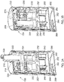
- Figures 3A-3B are schematic perspective views illustrating a partly cut-through arrangement for manipulating a door lock remote control device, in two different states.
- Figure 3A shows a state wherein a door lock remote control device 200 is to be inserted into or is being removed from the arrangement 100.
- Figure 3B shows a state wherein the door lock remote control device is fully inserted into and completely accommodated by the arrangement 100.
- the arrangement 100 for manipulating a door lock remote control device 200 comprises two actuating devices, which, in use, operates two respective pushbuttons 210, 212 in the door lock remote control device 200.
- the "in use" mode corresponds to the state illustrated in figure 3B .
- a receptacle 204 is configured to accommodate the door lock remote control device 200.
- the arrangement 100 also includes a surrounding casing 220, which may have a generally cylindrical shape, and which has an inner surface.
- the actuating device includes two cams 240 provided on the inner surface of the casing 200, at various positions along the rotational axis of the arrangement 100. The positions are selected so as to correspond with the positions of pusbuttons on the door lock remote control device 200 when the door lock remote control device 200 has been fully inserted in the arrangement 100, i.e., as shown in figure 3B .
- the receptacle 204 is configured to keep the door lock remote control device 200 in a fixed position with respect to the receptacle 204 during the relative rotational movement between the receptacle 204 and the surrounding casing 220.
- Figure 3B shows a state wherein the receptacle 204 and the surrounding casing 220 may rotate with respect to each other.
- the receptacle is also configured to follow the door lock remote control device 200 in an upper position, as shown in figure 3A , when the door lock remote control device is to be inserted into or removed from the arrangement 100. In the state shown in figure 3A , the receptacle 204 and the surrounding casing 220 are prevented from rotating with respect to each other.
- the receptacle 204 is rotary in the arrangement 100, and the surrounding casing 220 is stationary.
- the receptacle 204 may be stationary and the surrounding casing 220 may be rotary.
- the receptacle 204 and the surrounding casing 220 may be counterrotating.
- the actuating device, or cam may be provided on a rotating camshaft instead of on the inner surface of the surrounding casing 220.
- the receptacle 204 and the surrounding casing 220 may both be stationary.
- the camshaft, inducing one or more cams arranged on the camshaft is arranged in such a way as to manipulate the pushbutton or pushbuttons of the door lock remote control device 200 when the camshaft rotates, when the door lock remote control device is kept in a stationary position within the arrangement 100 by the receptacle 204.
- the actuating devices, or cams, 240 in particular their rotary positions, which influence their manipulation of the pushbuttons 210, 212, are remotely operable by wireless communication means. This may be achieved, e.g., in such a way as has been explained above with reference to figure 1 .
- the two actuating devices, or cams, 240 are operable to interact with the pushbuttons 210, 212 by a rotary relative movement between the door lock remote control device 100 and the actuating devices.
- the receptacle 204 when fully inserted into the arrangement 100, as shown in figure 3B , and the surrounding casing 220, are configured to move with a rotational movement with respect to each other.
- cams 240 pushes the respective pushbuttons in the door lock remote control device 200 at predetermined relative rotational positions between the receptacle 204 and the surrounding casing 220.
- the cams pushes the pushbuttons indirectly, via the movable cam followers 230, 232, which are configured to transfer the movement provided by the cams to the pushbuttons 210, 212 in the door lock remote control device.
- the rotary movement between the receptacle 204 and the casing 220 is provided by an electrical motor 250, such as a DC motor, a synchrone motor, or a step motor, encompassed in the arrangement 100.
- the motor 250 may be mechanically connected to a gear unit 252 which adapts the rotational speed and torque of the motor 250 to a suitable rotational speed and torque of the relative rotary movement between the receptacle 204 and the casing 220.
- the arrangement 100 may also include an electronic motor controller which provides a control signal or power signal to the motor 250.
- the motor controller may be operatively controlled by at least a signal provided by the wireless communication means mentioned above, in particular with reference to figure 1 .
- the arrangement shown in figures 3A and 3B also includes a lid 270 that may be opened and closed by the rotary movement between the receptacle 204 and the surrounding casing 220.
- the opening and closing assembly of the lid 270 may be arranged in such a way that the lid is open when the receptacle 204 and the surrounding casing are positioned at the same angular posision with respect to the axis of the device 100, i.e., as shown in figure 3A .
- the opening and closing assembly of the lid 204 may also be arranged in such a way that the lid is closed when the receptacle 204 and the surrounding casing are positioned at different angular positions, for instance when they are positioned at opposite angular positions as shown in figure 3B .
- opening of the lid enables propagation of radio signals betweeen the interior of the arrangement and the surroundings of the arrangement.
- This may be achieved by providing the casing 220, including its end faces, as a closed electrically conductive shield, i.e., as a Faraday cage.
- the casing 220 is in this case made of a metal or alloy such as aluminium or steel.
- the lower end face of the arrangement 100 may, as illustrated in figures 3A and 3B , include an inner metal lid 260,
- the inner metal lid 260 may include the same material as the casing 220, e.g., aluminium or steel.
- An outer, lower cover 266 may be provided at the bottom of the device 100.
- the lower cover 266 may advantageously be provided in a non-conducting material such as a plastic/resin material.
- An electronic wireless communiation circuit board 264 providing secondary wireless digital communication is provided in a compartment formed at the lower end of the arrangement 100.
- the lower lid cover ensures that the wireless communiation circuit board 264 is not captured by the Faraday cage, thus enabling secondary wireless communication even when the lid 270 is closed.
- An upper face of the arrangement 100 may likewise include the same electrically conductive material as the casing 220, e.g., aluminium or steel.
- the lid 270 may also include the same electrically conductive material as the casing 220, e.g., aluminium or steel.
- the lid 270 may, electrically, form part of the upper face when the lid 270 is closed.
- the lid 270 may provide an opening in the upper face of the arrangement 100 when the lid 270 is open.
- the lid 270 provides an access port for the door lock remote control device 200 to enter into or exit from the interior of the arrangement 100.
- the power supply may advantageously be provided as a battery 254, which may be rechargeable or disposable.
- the power supply may be provided as a line, cable or similar from an external power source, for instance in the vehicle.
- the arrangement 100 for manipulating a door lock remote control device 200 comprises at least one actuating device which, in use, enables the propagation of wireless signals between the door lock remote control device 200 and a door lock remote control receiver device in the vehicle.
- the at least one actuating device is remotely operable by wireless communication means, and is operable to enable the propagation of wireless signals between the door lock remote control device 200 and the door lock remote control receiver device in the vehicle by a rotary relative movement between the door lock remote control device and the at least one actuating device.
- the door lock remote control device does not necessarily include push buttons. Instead, the mere presence of the door lock remote control device within the radio range of the door lock remote control receiver device in the vehicle will enable unlocking of the vehicle lock, thus allowing the user to access the vehicle, e.g. when operating a switch at the vehicle door.
- the opening of the lid 270 provided by the rotary relative movement between the door lock remote control device and the actuating device, results in that the door lock remote control device is found to be within the radio range of the door lock remote control receiver.
- Figure 4 is schematic perspective view illustrating the external of the arrangement for manipulating a door lock remote control device in two different states.
- the lid 270 is closed, forming a Faraday cage which prevents radio signals from propagating effectively through the casing 220.
- the lid 270 is open, allowing radio signals to propagate through the casing 220 of the arrangement 100. Also, the open lid provides an access port for the lock remote control device 200. Part of the receptacle 204 has been shown in an elevated position, protruding through the opening that was closed by the lid 270 in figure 4A .
- the lower, non-conducting cover of the arrangement 100 has also been shown at 266.
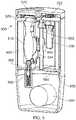
- Figure 5 is a schematic perspective view illustrating a partly cut-through arrangement 500 for manipulating a door lock remote control device.
- the arrangement 500 shown in figure 5 also comprises at least one actuating device which, in use, operates at least one respective pushbutton in the door lock remote control device 510.
- the arrangement 500 includes two actuating devices which, in use, operate two respective pushbuttons in the door lock remote control device. Other numbers of actuating devices are possible, for instance one, three, four or more.
- the at least one actuating device is remotely operable by wireless communication means.
- the at least one actuating device is operable to interact with the at least one pushbutton by a rotary relative movement between the door lock remote control device and the at least one actuating device.
- the door lock remote control device may be a vehicle door lock remote control device.
- the rotary relative movement between the door lock remote control device and the at least one actuating device is not provided by a surrounding casing with at lease one cam on its inside. Instead, the rotary movement between the door lock remote control device 510 and the at least one actuating device is provided by at least one cam provided externally on a rotating camshaft.
- the receptacle 504 and the surrounding casing 520 are both stationary.
- the camshaft 580, inducing one or more cams 542, 544 arranged on the camshaft, is arranged in such a way as to manipulate, directly or indirectly, the pushbutton or pushbuttons of the door lock remote control device 510 when the camshaft rotates.
- a receptacle 504 is configured to accommodate the door lock remote control device 510.
- the arrangement 500 also includes a surrounding casing 520, which may have a generally cylindrical shape.
- the actuating device includes two cams 542, 544 provided on the exterior surface of the rotatable camshaft 580, at various positions along the camshaft 580.
- the positions may be selected so as to correspond with positions of levers or flaps, which may be part of the receptacle 504, and which serve to transfer a force between the rotating cam and a respective pusbutton on the door lock remote control device 510 held within the receptacle 504.
- the camshaft 580 may be arranged centrally within the surrounding casing, for instance with its axis coincident with the cylindric surrounding casing 520, or with its axis offset and parallel to the axis of the cylindric surrounding casing 520.
- the receptacle 504 is configured to keep the door lock remote control device 510 in a fixed position with respect to the surrounding casing 520 during the relative rotational movement between the receptacle 204 and the camshaft 542.
- the receptacle 504 may also be configured to follow the door lock remote control device 510 to an upper position (not shown) when the door lock remote control device is to be inserted into or removed from the arrangement 500.
- the arrangement 500 may comprise a spring-loaded double-click mechanism 590 for retracting and rejecting/projecting the receptacle 504 from the surrounding casing 520.
- a double-clicking mechanism ensures that the receptacle 504 is engaged within the surrounding casing 520, i.e., retracted, at a first external depression by a user. At a second depression by the user, the double-click mechanism will reject the receptacle 504, or at least project it out of the surrounding casing 520.
- the actuating devices in this case the cams 542, 544, and in particular their rotary positions, which influence their manipulation of the pushbuttons, are remotely operable by wireless communication means. This may be achieved, e.g., in a corresponding way as has been explained above with reference to figure 1 .
- the rotary movement of the camshaft 580 may be provided by an electrical motor 550, such as a DC motor, a synchrone motor, or a step motor, encompassed in the arrangement 500.
- the motor 550 may be mechanically connected to a gear unit 552 which adapts the rotational speed and torque of the motor 550 to a suitable rotational speed and torque of the camshaft 580.
- the arrangement 500 may also include an electronic motor controller which provides a control signal or power signal to the motor 550.
- the motor controller may be operatively controlled by at least a signal provided by the wireless communication means mentioned above, in particular with reference to figure 1 .
- the arrangement shown in figure 5 also includes a lid 570 that may be opened and closed by the rotary movement of the motor 550 and the gear 552.
- opening of the lid enables propagation of radio signals betweeen the interior of the arrangement and the surroundings of the arrangement.
- This may be achieved by providing the casing 520, including its end faces, as a closed electrically conductive shield, i.e., as a Faraday cage.
- the casing 520 is in this case made of a metal or alloy such as aluminium or steel.
- the lower end face of the arrangement 500 may, as illustrated in figure 5 , include an inner metal lid 560.
- the inner metal lid 560 may include the same material as the casing 520, e.g., aluminium or steel.
- An outer, lower cover or cup 566 may be provided at the bottom of the device 500.
- the lower cover 566 may advantageously be provided in a non-conducting material such as a plastic/resin material.
- An electronic wireless communiation circuit board 564 providing secondary wireless digital communication is provided in a compartment formed at the lower end of the arrangement 500. The lower lid cover ensures that the wireless communiation circuit board 564 is not captured by the Faraday cage, thus enabling secondary wireless communication even when the lid 570 is closed.
- An upper face of the arrangement 500 may likewise include the same electrically conductive material as the casing 520, e.g., aluminium or steel.
- the lid 570 may also include the same electrically conductive material as the casing 520, e.g., aluminium or steel.
- the lid 570 may, electrically, form part of the upper face when the lid 570 is closed.
- the lid 570 may provide an opening in the upper face of the arrangement 500 when the lid 570 is open.
- the lid 570 provides an access port for the door lock remote control device 510 to enter into or exit from the interior of the arrangement 500.
- An electric power supply for powering power-consuming components may be included in the arrangement 500.
- the power supply may advantageously be provided as a battery 554, which may be rechargeable or disposable.
- the power supply may be provided as a line, cable or similar from an external power source, for instance in the vehicle.
- Figure 6 is a schematic view of a removable receptacle 504 configured to accommodate a door lock remote control device 510 within a surrounding casing.
- the receptacle 504 includes a closure, such as a cradle or drawer, which is removable from the casing 500.
- the receptacle includes two protruding flaps 513, 514, which are configured to transfer a movement provided by respective cams on a rotatable camshaft to two corresponding pushbuttons 511, 512 in the door lock remote control device 510.
- the receptacle 504 may have further features as illustrated and described above with reference to figure 5 and the corresponding detailed description.
- the present invention may provide numerous advantages over the background art.
- the rotary operation principle of the invention makes it possible to use only one actuator, i.e., an electric motor, for providing several functions, including operating more than one pushbutton of the door remote control device.
- several linear actuators were needed. Linear actuators are generally more expensive, may lead to a bulky design, and may result in less reliable and robust operation over time, as well as a more complex manufacturing process.
- the rotary operation principle also facilitates the design of the arrangement according to the invention as a generally/substantially cylindrical unit.
- Such a design makes it easy to install the arrangement temporarily in a regular vehicle compartment, since such compartments usually include one or more cup or bottle holders that may be suitable for keeping the arrangement 100 within the vehicle compartment.
- the cylindrical design allows robustness and ruggedness.
- the former arrangements based on a drawer and with linear actuators to operate pushbuttons, would usually need to be operated by two hands.
- the present invention may provide easy one-hand operation, including the insertion/removal of the door lock remote control device, by a user.
Landscapes
- Physics & Mathematics (AREA)
- General Physics & Mathematics (AREA)
- Engineering & Computer Science (AREA)
- Manufacturing & Machinery (AREA)
- Lock And Its Accessories (AREA)
Description
- The present invention relates to an arrangement for manipulating a vehicle door lock remote control device.
- A vehicle, such as a car, is usually accessed by means of a wireless remote control device. In general, such a wireless remote control device allows the doors of the vehicle to be unlocked and locked from a location near the vehicle.
- Such a remote control device may transmit a radio signal that is coded by a code, which is unique to the vehicle. In this way, it is ensured that the operation of the remote control device results in that the doors of the vehicle actually associated with the remote control is unlocked or locked by the manual operation of this particular remote control device.
- This type of remote control device is often designed as a handheld, miniature housing, which accommodates a battery, electronic circuitry including a radio transmitter, and at least one manually operated switch, usually in the form of pushbutton. Usually, two pushbuttons are provided. Pushing the first pushbutton leads to the transmitter transmitting a radio signal coded with an unlocking instruction code. Pushing the second pushbutton leads to the transmitter transmitting a radio signal coded with a locking instruction code.
- Often the remote control device is combined with, or made as a part of, a physical key which may be used, e.g., to activate an ignition lock and start the engine of the vehicle. For instance, the handheld housing may serve as a handgrip of the physical key.
- This traditional solution is particularly useful for privately owned vehicles, which are typically driven by only one or a few persons, who bring their own key (with associated remote control device) with them.
- With modern mobility, in particular in urban areas, traditional private ownership of cars is expected to diminish. Instead, private car share arrangements and various types of car hire arrangements are emerging. When a car or other vehicle is supposed to be used by more than one or just a few users, the traditional approach of a physical key or a physical remote control device as a token for providing access to the vehicle becomes less practical.
- As an example, a car share service is usually managed entirely by digital communication, e.g. on the Internet. A participant of the service may reserve and be allocated a car merely by using an application on her/his mobile phone. It would be cumbersome if the user then had to obtain a physical key (or remote control device) in order to get access to the allocated vehicle.
- Full digital, key-less access systems are under development in new and future vehicles. Still, there is a need of solutions that makes use of a remote control device of the above-mentioned type, which makes it possible for a larger number of authorized users (for instance, participants in a car share service) to access and use the vehicle, without the need for physical hand-over of a physical key and/or physical remote control device. Avoiding use of the physical key may also have advantages when there is only one user of the car.
- One technique which solves this basic problem of the traditional art has been suggested by the disclosure of
DE-10 2005 059 061 A1 . This publication relates to a method and device that involves locking and unlocking a motor vehicle by a door lock that is remotely controlled by an opening signal that is controlled by a serial key. The opening signal is wirelessly transmitted to the vehicle by the key. The key is kept in a key box that is controlled by an activation unit, which is disposed for unlocking the vehicle by an auxiliary transmitter (operated by radio, infrared, Bluetooth, or mobile communication) to transmit the opening signal and to activate a central locking system in the vehicle. To this end, the key box includes pressing elements, which may be linear motors or electromagnetic actuators, and which are controlled by the auxiliary transmitter. -
EP-1 808 336 A1 also discloses an access control device for a motor vehicle. The device has a vehicle key kept inside the vehicle, in such a way that the key is set in operation by a remote control device from outside the vehicle for locking and unlocking of a door lock. The key is movably mounted in a drawer within the vehicle. An actuation unit is moved by a linear drive. The actuation unit is set in operation by the remote control device for operating the vehicle key, which is provided in the drawer of the vehicle. -
WO2017/168341A1 discloses a safety device for holding and sharing a key provided with a remote control. The safety device comprises an actuating device that in use operates a push button in the remote control. It is remotely operated by a wireless transmission unit, where the actuating device includes a cam operable to interact with the push button by a relative movement between the remote control and the cam. The actuating device may also open and close a lock that prevents a user from separating a first half shell from a second half shell. - These solutions of the background art still have certain shortcomings or disadvantages, for instance in respect of user-friendliness, robustness, ease of operation, and ease of manufacturing.
- The invention provides an improved arrangement for manipulating a door lock remote control device, which remedies or at least alleviates certain drawbacks of arrangements disclosed in the background art.
- The invention has been set forth in the appended claims.
-
-
Figure 1 is a schematic perspective view of a system wherein an arrangement for manipulating a door lock remote control device is used, -
Figures 2A-2C are three schematic diagrams illustrating the actuation of pushbuttons by a rotary relative movement between a door lock remote control device and an actuating device, -
Figures 3A-3B are schematic perspective views illustrating a partly cut-through arrangement for manipulating a door lock remote control device, in two different states. -
Figure 4 is schematic perspective view illustrating the external of the arrangement for manipulating a door lock remote control device in two different states. -
Figure 5 is a schematic perspective view illustrating a partly cut-through arrangement for manipulating a door lock remote control device. -
Figure 6 is a schematic view of a removable receptacle configured to accommodate a door lock remote control device within a surrounding casing. - The invention shall be described by non-limiting examples with reference to the figures.
-
Figure 1 is a schematic perspective view of a system wherein an arrangement for manipulating a door lock remote control device is used. - A vehicle, for instance a passenger car, is shown at 110. The
vehicle 110 is equipped with power door locks (not shown) that may be remotely operated by means of a door lock remote control device. The door lock remote control device has not been shown infigure 1 , but may be recognized withreference numeral 200 in the remaining figures. - The arrangement according to the invention may alternatively be used in conjunction with a garage. In such a case, the door lock remote control device may control the locking and unlocking of a garage door.
- The door lock remote control device may be in the form of a handle of a physical key which is used with an ignition lock switch in the vehicle to turn on the ignition and to start the car.
- Traditionally, such a door lock remote control device is carried by the driver when he or she is outside the car. The door lock remote control device is typically equipped with at least one pushbutton, often two pushbuttons. The driver may unlock the vehicle's door locks by pressing the first pushbutton and lock the vehicle's door locks by pressing the second pushbutton. A third and fourth pushbutton may in some cases be provided, typically for opening the vehicle's luggage compartment or fuel tank cap. In some cases, the door lock remote control device has only one pushbutton, and locking/unlocking is provided by specified time sequences of operation of the one pushbutton.
- The door lock remote control device is configured to transmit a radio signal that is encoded with a particular code when each of its buttons is pressed. A receiver in the vehicle is configured to respond to these particular codes, resulting in appropriate action in the car, i.e., locking and unlocking a door.
- In the system shown in
figure 1 , the doors lock remote control device is kept within anarrangement 100, which is located in the vehicle compartment. Thearrangement 100 is an arrangement for manipulating the door lock remote control device. In one aspect of the invention, it comprises at least one actuating device which, in use, operates at least one respective pushbutton in the door lock remote control device. In a typical example, thearrangement 100 for manipulating the door lock remote control device includes two actuating devices which, in use, operate two respective pushbuttons in the door lock remote control device. - The at least one actuating device is remotely operable by wireless communication means. This is illustrated by the
wireless communication device 120 and theremote service 130. Thewireless communication device 120 and theremote service 130 are configured to inter-communicate over a wireless network, for instance via mobile communication network, such as a GSM, 3G and/or 4G network, or via a local wireless network (WLAN), or both. Theremote service 130 has been illustrated as a cloud service, in which case the provided service may be achieved by sharing of computer resources across several computing entities or data centers across the network. However, theremote service 130 may also be provided by a single, particular server computer operating in the wireless network. - The at least one actuating device in the
arrangement 100 for manipulating the door lock remote control device may in one aspect be remotely operated directly from thewireless communication device 120, for instance by means of short-range wireless communication, such as Bluetooth or WLAN, or alternatively, by means of an optical (e.g., infrared) communication link. - In another aspect, the door lock remote control device may be operated by the
wireless communication device 120 indirectly, over the wireless network, e.g., GSM, 3G, 4G and/or WLAN. In this aspect, the communication between thewireless communication device 120 and the door lock remote control device may be achieved by means of various network elements, for instance including the illustratedservice 130. - According to one aspect of the invention, the at least one actuating device in the
arrangement 100 is operable to interact with the at least one pushbutton in the door lock remote control device by a rotary relative movement between the door lock remote control device and the at least one actuating device. The rotary movement may be provided by an electrical motor encompassed in the arrangement, and an electronic motor controller, operatively controlled by at least a signal provided by the wireless communication means. - Further exemplary details of the operation of the actuating device(s) in the
arrangement 100 will be explained below, in particular with reference tofigures 2A-C and3A-B . - As an alternative to the traditional approach, wherein a door of the
vehicle 110 is locked and unlocked by operating at pushbutton in the door lock remote control device, a "keyless entry" function may be provided. In this case the vehicle door may be opened or locked by the operation of a button on the vehicle's door handle, provided that the remote control device is located within the communication range of the vehicle's door lock remote control receiver. - According to this alternative approach, the actuating device in the arrangement for manipulating a door lock remote control device will, in use, enable the propagation of wireless signals between the door lock remote control device and the door lock remote control receiver device. This propagation of wireless signals between the door lock remote control device and the door lock remote control receiver device may be achieved by a rotary relative movement between the door lock remote control device and the at least one actuating device.
- In any of the above-mentioned approaches, the
arrangement 100 may further comprise a lid to be opened and closed by the rotary movement between the receptacle and the surrounding casing. The opening of the lid may enable the propagation of radio signals betweeen the interior of the arrangement and the surroundings of the arrangement. - The lid may further provide an access port for the vehicle door lock remote control device to enter into or exit from the interior of the
arrangement 100. -
Figures 2A-2C are three schematic diagrams illustrating the actuation of pushbuttons by a rotary relative movement between a door lockremote control device 200 and anactuating device 240. - Each of the
figures 2A, 2B and 2C illustrates schematically a cross-section of thearrangement 100 for manipulating a door lock remote control device, viewed in the direction of a rotational axis of thearrangement 100. - As already explained with reference to
figure 1 , thearrangement 100 includes at least oneactuating device 240 which, in use, operates at least onerespective pushbutton remote control device 200. - The at least one
actuating device 240 is operable to interact with the at least onepushbutton remote control device 200 and the at least oneactuating device 240. - The
arrangement 100 comprises a receptacle (not illustrated infigures 2A, 2B, 2C ). which is configured to accommodate the door lockremote control device 200. Thearrangement 100 also includes acasing 220 that surrounds the receptacle and the lockremote control device 200 accommodated in the receptacle. - The receptacle may be configured to keep the door lock
remote control device 200 in a fixed position with respect to the receptacle, in particular during the relative rotational movement between the receptacle and the surrounding casing. - The
casing 220 may have an inner surface, and the at least one actuating device may include at least onecam 240 provided on the inner surface of thecasing 220. The or each cam may be provided in the form of a protrusion or projected area of the inner surface. The receptacle and the surroundingcasing 220 may be configured to move with a rotational movement with respect to each other, in such a way that thecam 240 directly or indirectly pushes the pushbutton(s) 210, 212 in the door lockremote control device 200 at a predetermined relative rotational position between the receptacle and the surroundingcasing 220. - In the example shown in
figures 2A , thearrangement 100 comprises oneactuating device 240 which, in use, operates tworespective pushbuttons remote control device 200. The operation of therespective pushbuttons casing 220. The provision of such movement will be explained later, in particular with reference tofigures 3A -3C below. -
Figure 2B corresponds largely to the arrangement shown infigure 2A , but infigure 2B the door lockremote control device 200 has been located at a lower level than in the example offigure 2A , i.e., at a level close to a central rotary axis of thearrangement 100. Also, the door lockremote control device 200 has been illustrated with only onepushbutton 210, as opposed to the two pushbuttons shown infigure 2A . In order to operate thepushbutton 210, which has been located at a larger distance from the inner surface of thecasing 220, thearrangement 100 infigure 2B includes at least onemovable cam follower 230. One such cam follower has been illustrated infigure 2B . The cam follower is configured to transfer the movement provided by thecam 240 to thepushbutton 210 in the door lockremote control device 200. Thecam follower 230 may in the simplest case be a rigid rod, which is guided by suitable guiding means (not shown) to obtain a linear, slidable movement. - Although only one
pushbutton 210, onecam follower 230 and onecam 240 have been shown infigure 2B , it should be understood that two or more pushbuttons may be arranged in the door lockremote control device 200 along the axis of thearrangement 100, i.e., in intersections not shown onfigure 2B . In this case, two ormore cam followers 230 andcams 240 are arranged at corresponding positions, allowing thecams 240 andcam followers 230 to manipulate respective pushbuttons in the door lockremote control device 200. -
Figure 2C corresponds tofigure 2B , except that thecam follower 232 infigure 2C has been provided as a spring-loaded rod with an end stop in the form of a flange, which keeps a spring in place and which may also limit the range of linear travelling of the cam follower. Further, the upper end of thecam follower 232 has been provided with a free-running wheel or roller, which provides a more proper, less-friction interaction with thecam 240. - In any of the examples shown in
figures 2A-2C , there are several possibilities for the relative movement between the receptacle and the surrounding casing. In one aspect, the receptacle may be stationary and the surroundingcasing 220, which has one or more cams on its inner surface) may be rotary. In another aspect, the receptacle may be rotary and the surroundingcasing 220 may be stationary. In still another aspect, the receptacle and the surroundingcasing 220 may be counterrotating. -
Figures 3A-3B are schematic perspective views illustrating a partly cut-through arrangement for manipulating a door lock remote control device, in two different states. -
Figure 3A shows a state wherein a door lockremote control device 200 is to be inserted into or is being removed from thearrangement 100.Figure 3B shows a state wherein the door lock remote control device is fully inserted into and completely accommodated by thearrangement 100. - In both cases, i.e. in both
figures, 3A and 3B , thearrangement 100 for manipulating a door lockremote control device 200 comprises two actuating devices, which, in use, operates tworespective pushbuttons remote control device 200. The "in use" mode corresponds to the state illustrated infigure 3B . - A
receptacle 204 is configured to accommodate the door lockremote control device 200. Thearrangement 100 also includes a surroundingcasing 220, which may have a generally cylindrical shape, and which has an inner surface. The actuating device includes twocams 240 provided on the inner surface of thecasing 200, at various positions along the rotational axis of thearrangement 100. The positions are selected so as to correspond with the positions of pusbuttons on the door lockremote control device 200 when the door lockremote control device 200 has been fully inserted in thearrangement 100, i.e., as shown infigure 3B . - The
receptacle 204 is configured to keep the door lockremote control device 200 in a fixed position with respect to thereceptacle 204 during the relative rotational movement between thereceptacle 204 and the surroundingcasing 220.Figure 3B shows a state wherein thereceptacle 204 and the surroundingcasing 220 may rotate with respect to each other. - The receptacle is also configured to follow the door lock
remote control device 200 in an upper position, as shown infigure 3A , when the door lock remote control device is to be inserted into or removed from thearrangement 100. In the state shown infigure 3A , thereceptacle 204 and the surroundingcasing 220 are prevented from rotating with respect to each other. - Usually, as shown, the
receptacle 204 is rotary in thearrangement 100, and the surroundingcasing 220 is stationary. In alternative configurations, thereceptacle 204 may be stationary and the surroundingcasing 220 may be rotary. Still alternatively, thereceptacle 204 and the surroundingcasing 220 may be counterrotating. - Although not illustrated in the figures, the actuating device, or cam, may be provided on a rotating camshaft instead of on the inner surface of the surrounding
casing 220. In this case thereceptacle 204 and the surroundingcasing 220 may both be stationary. The camshaft, inducing one or more cams arranged on the camshaft is arranged in such a way as to manipulate the pushbutton or pushbuttons of the door lockremote control device 200 when the camshaft rotates, when the door lock remote control device is kept in a stationary position within thearrangement 100 by thereceptacle 204. - The actuating devices, or cams, 240, in particular their rotary positions, which influence their manipulation of the
pushbuttons figure 1 . - The two actuating devices, or cams, 240, are operable to interact with the
pushbuttons remote control device 100 and the actuating devices. - The
receptacle 204, when fully inserted into thearrangement 100, as shown infigure 3B , and the surroundingcasing 220, are configured to move with a rotational movement with respect to each other. During this movement,cams 240 pushes the respective pushbuttons in the door lockremote control device 200 at predetermined relative rotational positions between thereceptacle 204 and the surroundingcasing 220. The cams pushes the pushbuttons indirectly, via themovable cam followers pushbuttons - The rotary movement between the
receptacle 204 and thecasing 220 is provided by anelectrical motor 250, such as a DC motor, a synchrone motor, or a step motor, encompassed in thearrangement 100. Themotor 250 may be mechanically connected to agear unit 252 which adapts the rotational speed and torque of themotor 250 to a suitable rotational speed and torque of the relative rotary movement between thereceptacle 204 and thecasing 220. Thearrangement 100 may also include an electronic motor controller which provides a control signal or power signal to themotor 250. The motor controller may be operatively controlled by at least a signal provided by the wireless communication means mentioned above, in particular with reference tofigure 1 . - The arrangement shown in
figures 3A and 3B also includes alid 270 that may be opened and closed by the rotary movement between thereceptacle 204 and the surroundingcasing 220. The opening and closing assembly of thelid 270 may be arranged in such a way that the lid is open when thereceptacle 204 and the surrounding casing are positioned at the same angular posision with respect to the axis of thedevice 100, i.e., as shown infigure 3A . The opening and closing assembly of thelid 204 may also be arranged in such a way that the lid is closed when thereceptacle 204 and the surrounding casing are positioned at different angular positions, for instance when they are positioned at opposite angular positions as shown infigure 3B . - In a useful aspect, opening of the lid enables propagation of radio signals betweeen the interior of the arrangement and the surroundings of the arrangement. This may be achieved by providing the
casing 220, including its end faces, as a closed electrically conductive shield, i.e., as a Faraday cage. Thecasing 220 is in this case made of a metal or alloy such as aluminium or steel. When the lid is closed, it will form part of the Faraday cage and prevent propagation of radio signals, or at least attenuate such signals, between the interior and the exterior of thedevice 100. When the lid is opened, propagation of radio signals will be allowed and/or facilitated between the interior and the exterior of thedevice 100. - The lower end face of the
arrangement 100 may, as illustrated infigures 3A and 3B , include aninner metal lid 260, Theinner metal lid 260 may include the same material as thecasing 220, e.g., aluminium or steel. - An outer,
lower cover 266 may be provided at the bottom of thedevice 100. Thelower cover 266 may advantageously be provided in a non-conducting material such as a plastic/resin material. An electronic wirelesscommuniation circuit board 264 providing secondary wireless digital communication is provided in a compartment formed at the lower end of thearrangement 100. The lower lid cover ensures that the wirelesscommuniation circuit board 264 is not captured by the Faraday cage, thus enabling secondary wireless communication even when thelid 270 is closed. - An upper face of the
arrangement 100 may likewise include the same electrically conductive material as thecasing 220, e.g., aluminium or steel. Thelid 270 may also include the same electrically conductive material as thecasing 220, e.g., aluminium or steel. Thelid 270 may, electrically, form part of the upper face when thelid 270 is closed. Thelid 270 may provide an opening in the upper face of thearrangement 100 when thelid 270 is open. - Advantageously, the
lid 270 provides an access port for the door lockremote control device 200 to enter into or exit from the interior of thearrangement 100. - An electric power supply for powering power-consuming components may be included in the
arrangement 100. The power supply may advantageously be provided as abattery 254, which may be rechargeable or disposable. Alternatively, the power supply may be provided as a line, cable or similar from an external power source, for instance in the vehicle. - In an alternative embodiment of the
arrangement 100, thearrangement 100 for manipulating a door lockremote control device 200 comprises at least one actuating device which, in use, enables the propagation of wireless signals between the door lockremote control device 200 and a door lock remote control receiver device in the vehicle. The at least one actuating device is remotely operable by wireless communication means, and is operable to enable the propagation of wireless signals between the door lockremote control device 200 and the door lock remote control receiver device in the vehicle by a rotary relative movement between the door lock remote control device and the at least one actuating device. - In this alternative embodiment, the door lock remote control device does not necessarily include push buttons. Instead, the mere presence of the door lock remote control device within the radio range of the door lock remote control receiver device in the vehicle will enable unlocking of the vehicle lock, thus allowing the user to access the vehicle, e.g. when operating a switch at the vehicle door.
- In this case, the opening of the
lid 270, provided by the rotary relative movement between the door lock remote control device and the actuating device, results in that the door lock remote control device is found to be within the radio range of the door lock remote control receiver. - When the lid is closed, the lid and the remaining
casing 200, including its end faces, form a Faraday cage which prevents radio signals from propagating effectively through the casing. This results in that the vehicle will remain locked. - The remaining elements and features of the alternative embodiment of the
arrangement 100 may correspond to what has been disclosed above with reference tofigures 1 ,2A-2C ,3A-3B , and below with reference tofigure 4A-4B . -
Figure 4 is schematic perspective view illustrating the external of the arrangement for manipulating a door lock remote control device in two different states. - In the first state, illustrated in
figure 4A , thelid 270 is closed, forming a Faraday cage which prevents radio signals from propagating effectively through thecasing 220. - In the second state, illustrated in
figure 4B , thelid 270 is open, allowing radio signals to propagate through thecasing 220 of thearrangement 100. Also, the open lid provides an access port for the lockremote control device 200. Part of thereceptacle 204 has been shown in an elevated position, protruding through the opening that was closed by thelid 270 infigure 4A . - The lower, non-conducting cover of the
arrangement 100 has also been shown at 266. -
Figure 5 is a schematic perspective view illustrating a partly cut-througharrangement 500 for manipulating a door lock remote control device. - As is the case with the previously described embodiments of the arrangement for manipulating a door lock remote control device, the
arrangement 500 shown infigure 5 also comprises at least one actuating device which, in use, operates at least one respective pushbutton in the door lockremote control device 510. Advantageously, thearrangement 500 includes two actuating devices which, in use, operate two respective pushbuttons in the door lock remote control device. Other numbers of actuating devices are possible, for instance one, three, four or more. The at least one actuating device is remotely operable by wireless communication means. The at least one actuating device is operable to interact with the at least one pushbutton by a rotary relative movement between the door lock remote control device and the at least one actuating device. The door lock remote control device may be a vehicle door lock remote control device. - However, in the embodiment of the
arrangement 500 shown infigure 5 , the rotary relative movement between the door lock remote control device and the at least one actuating device is not provided by a surrounding casing with at lease one cam on its inside. Instead, the rotary movement between the door lockremote control device 510 and the at least one actuating device is provided by at least one cam provided externally on a rotating camshaft. - In this case the
receptacle 504 and the surroundingcasing 520 are both stationary. Thecamshaft 580, inducing one ormore cams remote control device 510 when the camshaft rotates. - The arrangement in
figure 5 has been shown in a state wherein the door lockremote control device 510 is fully inserted into and completely accommodated by thearrangement 100. - A
receptacle 504 is configured to accommodate the door lockremote control device 510. Thearrangement 500 also includes a surroundingcasing 520, which may have a generally cylindrical shape. - The actuating device includes two
cams rotatable camshaft 580, at various positions along thecamshaft 580. The positions may be selected so as to correspond with positions of levers or flaps, which may be part of thereceptacle 504, and which serve to transfer a force between the rotating cam and a respective pusbutton on the door lockremote control device 510 held within thereceptacle 504. - The
camshaft 580 may be arranged centrally within the surrounding casing, for instance with its axis coincident with the cylindricsurrounding casing 520, or with its axis offset and parallel to the axis of the cylindricsurrounding casing 520. - The
receptacle 504 is configured to keep the door lockremote control device 510 in a fixed position with respect to the surroundingcasing 520 during the relative rotational movement between thereceptacle 204 and thecamshaft 542. - The
receptacle 504 may also be configured to follow the door lockremote control device 510 to an upper position (not shown) when the door lock remote control device is to be inserted into or removed from thearrangement 500. In order to facilitate the insertion and removal of the door lockremote control device 510, thearrangement 500 may comprise a spring-loaded double-click mechanism 590 for retracting and rejecting/projecting thereceptacle 504 from the surroundingcasing 520. Such a double-clicking mechanism ensures that thereceptacle 504 is engaged within the surroundingcasing 520, i.e., retracted, at a first external depression by a user. At a second depression by the user, the double-click mechanism will reject thereceptacle 504, or at least project it out of the surroundingcasing 520. - The actuating devices, in this case the
cams figure 1 . - The rotary movement of the
camshaft 580 may be provided by anelectrical motor 550, such as a DC motor, a synchrone motor, or a step motor, encompassed in thearrangement 500. Themotor 550 may be mechanically connected to agear unit 552 which adapts the rotational speed and torque of themotor 550 to a suitable rotational speed and torque of thecamshaft 580. Thearrangement 500 may also include an electronic motor controller which provides a control signal or power signal to themotor 550. The motor controller may be operatively controlled by at least a signal provided by the wireless communication means mentioned above, in particular with reference tofigure 1 . - The arrangement shown in
figure 5 also includes alid 570 that may be opened and closed by the rotary movement of themotor 550 and thegear 552. - In a useful aspect, opening of the lid enables propagation of radio signals betweeen the interior of the arrangement and the surroundings of the arrangement. This may be achieved by providing the
casing 520, including its end faces, as a closed electrically conductive shield, i.e., as a Faraday cage. Thecasing 520 is in this case made of a metal or alloy such as aluminium or steel. When the lid is closed, it will form part of the Faraday cage and prevent propagation of radio signals, or at least attenuate such signals, between the interior and the exterior of thedevice 500. When the lid is opened, propagation of radio signals will be allowed and/or facilitated between the interior and the exterior of thedevice 500. - The lower end face of the
arrangement 500 may, as illustrated infigure 5 , include aninner metal lid 560. Theinner metal lid 560 may include the same material as thecasing 520, e.g., aluminium or steel. - An outer, lower cover or
cup 566 may be provided at the bottom of thedevice 500. Thelower cover 566 may advantageously be provided in a non-conducting material such as a plastic/resin material. An electronic wirelesscommuniation circuit board 564 providing secondary wireless digital communication is provided in a compartment formed at the lower end of thearrangement 500. The lower lid cover ensures that the wirelesscommuniation circuit board 564 is not captured by the Faraday cage, thus enabling secondary wireless communication even when thelid 570 is closed. - An upper face of the
arrangement 500 may likewise include the same electrically conductive material as thecasing 520, e.g., aluminium or steel. Thelid 570 may also include the same electrically conductive material as thecasing 520, e.g., aluminium or steel. Thelid 570 may, electrically, form part of the upper face when thelid 570 is closed. Thelid 570 may provide an opening in the upper face of thearrangement 500 when thelid 570 is open. - Advantageously, the
lid 570 provides an access port for the door lockremote control device 510 to enter into or exit from the interior of thearrangement 500. - An electric power supply for powering power-consuming components may be included in the
arrangement 500. The power supply may advantageously be provided as abattery 554, which may be rechargeable or disposable. Alternatively, the power supply may be provided as a line, cable or similar from an external power source, for instance in the vehicle. -
Figure 6 is a schematic view of aremovable receptacle 504 configured to accommodate a door lockremote control device 510 within a surrounding casing. - The
receptacle 504 includes a closure, such as a cradle or drawer, which is removable from thecasing 500. The receptacle includes two protrudingflaps corresponding pushbuttons remote control device 510. - The
receptacle 504 may have further features as illustrated and described above with reference tofigure 5 and the corresponding detailed description. - The present invention may provide numerous advantages over the background art. For instance, the rotary operation principle of the invention makes it possible to use only one actuator, i.e., an electric motor, for providing several functions, including operating more than one pushbutton of the door remote control device. In the background art, several linear actuators were needed. Linear actuators are generally more expensive, may lead to a bulky design, and may result in less reliable and robust operation over time, as well as a more complex manufacturing process.
- The rotary operation principle also facilitates the design of the arrangement according to the invention as a generally/substantially cylindrical unit. Such a design makes it easy to install the arrangement temporarily in a regular vehicle compartment, since such compartments usually include one or more cup or bottle holders that may be suitable for keeping the
arrangement 100 within the vehicle compartment. Also, the cylindrical design allows robustness and ruggedness. - The former arrangements, based on a drawer and with linear actuators to operate pushbuttons, would usually need to be operated by two hands. The present invention may provide easy one-hand operation, including the insertion/removal of the door lock remote control device, by a user.
- The invention has been disclosed by non-limiting examples with reference to the figures. The scope of the invention is not limited to the exemplary detailed description above. Rather, the scope has been defined by the appended claims.
Claims (14)
- Arrangement (100, 500) for manipulating a door lock remote control device (200, 510) comprising at least one actuating device which, in use, operates at least one respective pushbutton (210, 212, 511, 512) in the door lock remote control device (200, 510) the at least one actuating device being remotely operable by wireless communication means (120, 130),
characterized in thatthe at least one actuating device includes at least one cam (240, 542, 544) operable to interact with the at least one pushbutton (210, 212, 511, 512) by a rotary relative movement between the door lock remote control device (200, 510) and the at least one cam (240, 542, 544); andthe arrangement (100, 500) further comprising a lid (270, 570) to be opened and closed by the rotary relative movement. - Arrangement (100, 500) according to claim 1, wherein the door lock remote control device (200, 510) is a vehicle door lock remote control device.
- Arrangement (100, 500) according to claim 1,
comprising two actuating devices which, in use, operate two respective pushbuttons in the door lock remote control device (200, 510). - Arrangement (100) according to one of the claims 1-3,
comprising a receptacle (204) configured to accommodate the door lock remote control device (200), and a surrounding casing (220), the casing (220) having an inner surface, the at least one cam (240) is provided on the inner surface, the receptacle (204) and the surrounding casing (220) being configured to move with a rotational movement with respect to each other, the at least one cam (240) directly or indirectly pushing the at least one pushbutton (210, 212) in the door lock remote control device (200) at a predetermined relative rotational position between the receptacle (204) and the surrounding casing (220). - Arrangement (100) according to claim 4,
further comprising at least one movable cam follower (230), configured to transfer the movement provided by the at least one cam (240) to the at least one pushbutton (210, 212) in the door lock remote control device (200). - Arrangement (100) according to claim 4 or 5,
wherein the receptacle (204) is configured to keep the door lock remote control device (200) in a fixed position with respect to the receptacle (204) during the relative rotational movement between the receptacle (204) and the surrounding casing (220). - Arrangement (100) according to one of the claims 4-6,
wherein the receptacle (204) is stationary and the surrounding casing (220) is rotary. - Arrangement (100) according to one of the claims 4-6,
wherein the receptacle (204) is rotary and the surrounding casing (220) is stationary. - Arrangement (500) according to one of the claims 1-3,
wherein the at least one cam (542, 544) is provided on a rotating camshaft (580). - Arrangement (500) according to claim 9,comprising a receptacle (504) configured to accommodate the door lock remote control device (510), and a surrounding casing (520),the door lock remote control device (510) being held in a fixed position within the surrounding casing (520), the at least one cam (542, 544) on the camshaft (580) directly or indirectly pushing the at least one pushbutton (511, 512) in the door lock remote control device (500) at a predetermined relative rotational position between the receptacle (504) and the camshaft (580).
- Arrangement (500) according to claim 9 or 10,
wherein the receptacle (504) includes a removable closure which includes at least one protruding flap (513, 514), configured to transfer the movement provided by the at least one cam (542, 544) to the at least one pushbutton (511, 512) in the door lock remote control device (510). - Arrangement (500) according to claim 11,
further comprising a double-click mechanism (590) for retracting and projecting the receptacle (504) from the surrounding casing (520). - Arrangement (100, 500) according to one of the claims 1-12,
wherein the rotary movement is provided by an electrical motor (250, 550) encompassed in the arrangement (100, 500), and an electronic motor controller, operatively controlled by at least a signal provided by the wireless communication means (120, 130). - Arrangement according to one of the claims 1 - 13, wherein opening of the lid (270, 570) enables propagation of radio signals between the interior of the arrangement (100, 500) and the surroundings of the arrangement (100, 500).
Applications Claiming Priority (2)
| Application Number | Priority Date | Filing Date | Title |
|---|---|---|---|
| NO20161977 | 2016-12-13 | ||
| PCT/EP2017/082571 WO2018108984A1 (en) | 2016-12-13 | 2017-12-13 | Arrangement for manipulating a vehicle door lock remote control device |
Publications (2)
| Publication Number | Publication Date |
|---|---|
| EP3555392A1 EP3555392A1 (en) | 2019-10-23 |
| EP3555392B1 true EP3555392B1 (en) | 2022-06-22 |
Family
ID=61002970
Family Applications (1)
| Application Number | Title | Priority Date | Filing Date |
|---|---|---|---|
| EP17832055.2A Active EP3555392B1 (en) | 2016-12-13 | 2017-12-13 | Arrangement for manipulating a vehicle door lock remote control device |
Country Status (4)
| Country | Link |
|---|---|
| EP (1) | EP3555392B1 (en) |
| DK (1) | DK3555392T3 (en) |
| ES (1) | ES2927180T3 (en) |
| WO (1) | WO2018108984A1 (en) |
Families Citing this family (2)
| Publication number | Priority date | Publication date | Assignee | Title |
|---|---|---|---|---|
| CN111754660B (en) * | 2020-07-17 | 2024-09-06 | 东莞亚哲电子科技有限公司 | Emitter control box |
| CN112886181A (en) * | 2021-03-24 | 2021-06-01 | 深圳雷鸥克科技有限公司 | Signal shielding transmitting box capable of freely adjusting antenna length |
Citations (1)
| Publication number | Priority date | Publication date | Assignee | Title |
|---|---|---|---|---|
| DE102005059061B4 (en) * | 2005-12-08 | 2008-04-03 | Pincar Ag | Method and device for opening a vehicle |
Family Cites Families (2)
| Publication number | Priority date | Publication date | Assignee | Title |
|---|---|---|---|---|
| DE102006001410B4 (en) | 2006-01-11 | 2008-03-27 | Paragon Ag | Access control device for a motor vehicle |
| EP3437077B1 (en) * | 2016-04-01 | 2022-03-23 | Y.SHARE S.r.l. | Safety device for holding and sharing a key |
-
2017
- 2017-12-13 ES ES17832055T patent/ES2927180T3/en active Active
- 2017-12-13 DK DK17832055.2T patent/DK3555392T3/en active
- 2017-12-13 WO PCT/EP2017/082571 patent/WO2018108984A1/en not_active Ceased
- 2017-12-13 EP EP17832055.2A patent/EP3555392B1/en active Active
Patent Citations (1)
| Publication number | Priority date | Publication date | Assignee | Title |
|---|---|---|---|---|
| DE102005059061B4 (en) * | 2005-12-08 | 2008-04-03 | Pincar Ag | Method and device for opening a vehicle |
Also Published As
| Publication number | Publication date |
|---|---|
| EP3555392A1 (en) | 2019-10-23 |
| DK3555392T3 (en) | 2022-09-26 |
| ES2927180T3 (en) | 2022-11-03 |
| WO2018108984A1 (en) | 2018-06-21 |
Similar Documents
| Publication | Publication Date | Title |
|---|---|---|
| JP6949101B2 (en) | A secure device for holding and sharing keys | |
| JP4743669B2 (en) | Electronic key | |
| JP5801740B2 (en) | Locking device | |
| JP5801741B2 (en) | Locking device | |
| JP5758830B2 (en) | Locking device | |
| EP1402139B1 (en) | Closure control apparatus comprising a latch arrangement | |
| US8053922B2 (en) | Closing system for motor vehicles | |
| US11008776B2 (en) | Security device for holding and sharing a key | |
| US20170088099A1 (en) | Vehicle Key Apparatus | |
| CN101092863A (en) | Vehicle door control apparatus | |
| US20110214460A1 (en) | Door lock assembly | |
| US20200300006A1 (en) | Emergency actuating device for a movable part of a vehicle | |
| TWI760533B (en) | An electronic two-wheeler lock | |
| CN110573388B (en) | Container device for holding ID transmitter, insert for holding ID transmitter, and method for operating ID transmitter | |
| EP3555392B1 (en) | Arrangement for manipulating a vehicle door lock remote control device | |
| EP3693526B1 (en) | Actuating device for lock device and lock system comprising said actuating device | |
| US11859417B2 (en) | Locking device for car doors | |
| JP2014111858A (en) | Door unlocking/locking system using mobile phone with key | |
| KR20120105946A (en) | Dual security key system for vehicle and method for controlling the same | |
| KR102403510B1 (en) | Apparatus for emergency opening and closing of vehicle door | |
| CN206667981U (en) | A kind of car door lockhole safety theftproof device | |
| JP2001159264A (en) | Opening/closing panel for automobile with electric lock device delayingly unlockable | |
| JP2024134145A (en) | Housing device | |
| WO2025084216A1 (en) | Vehicle lock device | |
| KR20210001998A (en) | Vehicle start-up mechanism |
Legal Events
| Date | Code | Title | Description |
|---|---|---|---|
| STAA | Information on the status of an ep patent application or granted ep patent |
Free format text: STATUS: UNKNOWN |
|
| STAA | Information on the status of an ep patent application or granted ep patent |
Free format text: STATUS: THE INTERNATIONAL PUBLICATION HAS BEEN MADE |
|
| PUAI | Public reference made under article 153(3) epc to a published international application that has entered the european phase |
Free format text: ORIGINAL CODE: 0009012 |
|
| STAA | Information on the status of an ep patent application or granted ep patent |
Free format text: STATUS: REQUEST FOR EXAMINATION WAS MADE |
|
| 17P | Request for examination filed |
Effective date: 20190624 |
|
| AK | Designated contracting states |
Kind code of ref document: A1 Designated state(s): AL AT BE BG CH CY CZ DE DK EE ES FI FR GB GR HR HU IE IS IT LI LT LU LV MC MK MT NL NO PL PT RO RS SE SI SK SM TR |
|
| AX | Request for extension of the european patent |
Extension state: BA ME |
|
| DAV | Request for validation of the european patent (deleted) | ||
| DAX | Request for extension of the european patent (deleted) | ||
| STAA | Information on the status of an ep patent application or granted ep patent |
Free format text: STATUS: EXAMINATION IS IN PROGRESS |
|
| 17Q | First examination report despatched |
Effective date: 20201008 |
|
| REG | Reference to a national code |
Ref country code: DE Ref legal event code: R079 Ref document number: 602017058822 Country of ref document: DE Free format text: PREVIOUS MAIN CLASS: E05B0019000000 Ipc: E05B0081000000 |
|
| RIC1 | Information provided on ipc code assigned before grant |
Ipc: G07B 15/00 20110101ALN20211207BHEP Ipc: E05B 81/00 20140101AFI20211207BHEP |
|
| GRAP | Despatch of communication of intention to grant a patent |
Free format text: ORIGINAL CODE: EPIDOSNIGR1 |
|
| STAA | Information on the status of an ep patent application or granted ep patent |
Free format text: STATUS: GRANT OF PATENT IS INTENDED |
|
| INTG | Intention to grant announced |
Effective date: 20220118 |
|
| GRAS | Grant fee paid |
Free format text: ORIGINAL CODE: EPIDOSNIGR3 |
|
| GRAA | (expected) grant |
Free format text: ORIGINAL CODE: 0009210 |
|
| STAA | Information on the status of an ep patent application or granted ep patent |
Free format text: STATUS: THE PATENT HAS BEEN GRANTED |
|
| AK | Designated contracting states |
Kind code of ref document: B1 Designated state(s): AL AT BE BG CH CY CZ DE DK EE ES FI FR GB GR HR HU IE IS IT LI LT LU LV MC MK MT NL NO PL PT RO RS SE SI SK SM TR |
|
| REG | Reference to a national code |
Ref country code: GB Ref legal event code: FG4D |
|
| REG | Reference to a national code |
Ref country code: CH Ref legal event code: EP |
|
| REG | Reference to a national code |
Ref country code: DE Ref legal event code: R096 Ref document number: 602017058822 Country of ref document: DE |
|
| REG | Reference to a national code |
Ref country code: AT Ref legal event code: REF Ref document number: 1499871 Country of ref document: AT Kind code of ref document: T Effective date: 20220715 |
|
| REG | Reference to a national code |
Ref country code: IE Ref legal event code: FG4D |
|
| REG | Reference to a national code |
Ref country code: DK Ref legal event code: T3 Effective date: 20220921 |
|
| REG | Reference to a national code |
Ref country code: NL Ref legal event code: FP |
|
| REG | Reference to a national code |
Ref country code: LT Ref legal event code: MG9D |
|
| REG | Reference to a national code |
Ref country code: SE Ref legal event code: TRGR |
|
| PG25 | Lapsed in a contracting state [announced via postgrant information from national office to epo] |
Ref country code: LT Free format text: LAPSE BECAUSE OF FAILURE TO SUBMIT A TRANSLATION OF THE DESCRIPTION OR TO PAY THE FEE WITHIN THE PRESCRIBED TIME-LIMIT Effective date: 20220622 Ref country code: HR Free format text: LAPSE BECAUSE OF FAILURE TO SUBMIT A TRANSLATION OF THE DESCRIPTION OR TO PAY THE FEE WITHIN THE PRESCRIBED TIME-LIMIT Effective date: 20220622 Ref country code: GR Free format text: LAPSE BECAUSE OF FAILURE TO SUBMIT A TRANSLATION OF THE DESCRIPTION OR TO PAY THE FEE WITHIN THE PRESCRIBED TIME-LIMIT Effective date: 20220923 Ref country code: FI Free format text: LAPSE BECAUSE OF FAILURE TO SUBMIT A TRANSLATION OF THE DESCRIPTION OR TO PAY THE FEE WITHIN THE PRESCRIBED TIME-LIMIT Effective date: 20220622 Ref country code: BG Free format text: LAPSE BECAUSE OF FAILURE TO SUBMIT A TRANSLATION OF THE DESCRIPTION OR TO PAY THE FEE WITHIN THE PRESCRIBED TIME-LIMIT Effective date: 20220922 |
|
| REG | Reference to a national code |
Ref country code: ES Ref legal event code: FG2A Ref document number: 2927180 Country of ref document: ES Kind code of ref document: T3 Effective date: 20221103 |
|
| REG | Reference to a national code |
Ref country code: NO Ref legal event code: T2 Effective date: 20220622 |
|
| REG | Reference to a national code |
Ref country code: AT Ref legal event code: MK05 Ref document number: 1499871 Country of ref document: AT Kind code of ref document: T Effective date: 20220622 |
|
| PG25 | Lapsed in a contracting state [announced via postgrant information from national office to epo] |
Ref country code: RS Free format text: LAPSE BECAUSE OF FAILURE TO SUBMIT A TRANSLATION OF THE DESCRIPTION OR TO PAY THE FEE WITHIN THE PRESCRIBED TIME-LIMIT Effective date: 20220622 Ref country code: LV Free format text: LAPSE BECAUSE OF FAILURE TO SUBMIT A TRANSLATION OF THE DESCRIPTION OR TO PAY THE FEE WITHIN THE PRESCRIBED TIME-LIMIT Effective date: 20220622 |
|
| PG25 | Lapsed in a contracting state [announced via postgrant information from national office to epo] |
Ref country code: SM Free format text: LAPSE BECAUSE OF FAILURE TO SUBMIT A TRANSLATION OF THE DESCRIPTION OR TO PAY THE FEE WITHIN THE PRESCRIBED TIME-LIMIT Effective date: 20220622 Ref country code: SK Free format text: LAPSE BECAUSE OF FAILURE TO SUBMIT A TRANSLATION OF THE DESCRIPTION OR TO PAY THE FEE WITHIN THE PRESCRIBED TIME-LIMIT Effective date: 20220622 Ref country code: RO Free format text: LAPSE BECAUSE OF FAILURE TO SUBMIT A TRANSLATION OF THE DESCRIPTION OR TO PAY THE FEE WITHIN THE PRESCRIBED TIME-LIMIT Effective date: 20220622 Ref country code: PT Free format text: LAPSE BECAUSE OF FAILURE TO SUBMIT A TRANSLATION OF THE DESCRIPTION OR TO PAY THE FEE WITHIN THE PRESCRIBED TIME-LIMIT Effective date: 20221024 Ref country code: EE Free format text: LAPSE BECAUSE OF FAILURE TO SUBMIT A TRANSLATION OF THE DESCRIPTION OR TO PAY THE FEE WITHIN THE PRESCRIBED TIME-LIMIT Effective date: 20220622 Ref country code: CZ Free format text: LAPSE BECAUSE OF FAILURE TO SUBMIT A TRANSLATION OF THE DESCRIPTION OR TO PAY THE FEE WITHIN THE PRESCRIBED TIME-LIMIT Effective date: 20220622 Ref country code: AT Free format text: LAPSE BECAUSE OF FAILURE TO SUBMIT A TRANSLATION OF THE DESCRIPTION OR TO PAY THE FEE WITHIN THE PRESCRIBED TIME-LIMIT Effective date: 20220622 |
|
| PG25 | Lapsed in a contracting state [announced via postgrant information from national office to epo] |
Ref country code: PL Free format text: LAPSE BECAUSE OF FAILURE TO SUBMIT A TRANSLATION OF THE DESCRIPTION OR TO PAY THE FEE WITHIN THE PRESCRIBED TIME-LIMIT Effective date: 20220622 Ref country code: IS Free format text: LAPSE BECAUSE OF FAILURE TO SUBMIT A TRANSLATION OF THE DESCRIPTION OR TO PAY THE FEE WITHIN THE PRESCRIBED TIME-LIMIT Effective date: 20221022 |
|
| REG | Reference to a national code |
Ref country code: DE Ref legal event code: R097 Ref document number: 602017058822 Country of ref document: DE |
|
| PG25 | Lapsed in a contracting state [announced via postgrant information from national office to epo] |
Ref country code: AL Free format text: LAPSE BECAUSE OF FAILURE TO SUBMIT A TRANSLATION OF THE DESCRIPTION OR TO PAY THE FEE WITHIN THE PRESCRIBED TIME-LIMIT Effective date: 20220622 |
|
| PLBE | No opposition filed within time limit |
Free format text: ORIGINAL CODE: 0009261 |
|
| STAA | Information on the status of an ep patent application or granted ep patent |
Free format text: STATUS: NO OPPOSITION FILED WITHIN TIME LIMIT |
|
| 26N | No opposition filed |
Effective date: 20230323 |
|
| P01 | Opt-out of the competence of the unified patent court (upc) registered |
Effective date: 20230522 |
|
| PG25 | Lapsed in a contracting state [announced via postgrant information from national office to epo] |
Ref country code: SI Free format text: LAPSE BECAUSE OF FAILURE TO SUBMIT A TRANSLATION OF THE DESCRIPTION OR TO PAY THE FEE WITHIN THE PRESCRIBED TIME-LIMIT Effective date: 20220622 Ref country code: LU Free format text: LAPSE BECAUSE OF NON-PAYMENT OF DUE FEES Effective date: 20221213 |
|
| PGFP | Annual fee paid to national office [announced via postgrant information from national office to epo] |
Ref country code: GB Payment date: 20231128 Year of fee payment: 7 |
|
| PGFP | Annual fee paid to national office [announced via postgrant information from national office to epo] |
Ref country code: SE Payment date: 20231130 Year of fee payment: 7 Ref country code: NL Payment date: 20231129 Year of fee payment: 7 Ref country code: IT Payment date: 20231206 Year of fee payment: 7 Ref country code: IE Payment date: 20231212 Year of fee payment: 7 Ref country code: FR Payment date: 20231128 Year of fee payment: 7 Ref country code: DK Payment date: 20231208 Year of fee payment: 7 Ref country code: DE Payment date: 20231211 Year of fee payment: 7 |
|
| PGFP | Annual fee paid to national office [announced via postgrant information from national office to epo] |
Ref country code: BE Payment date: 20231128 Year of fee payment: 7 |
|
| PG25 | Lapsed in a contracting state [announced via postgrant information from national office to epo] |
Ref country code: HU Free format text: LAPSE BECAUSE OF FAILURE TO SUBMIT A TRANSLATION OF THE DESCRIPTION OR TO PAY THE FEE WITHIN THE PRESCRIBED TIME-LIMIT; INVALID AB INITIO Effective date: 20171213 |
|
| PGFP | Annual fee paid to national office [announced via postgrant information from national office to epo] |
Ref country code: ES Payment date: 20240109 Year of fee payment: 7 |
|
| PG25 | Lapsed in a contracting state [announced via postgrant information from national office to epo] |
Ref country code: CY Free format text: LAPSE BECAUSE OF FAILURE TO SUBMIT A TRANSLATION OF THE DESCRIPTION OR TO PAY THE FEE WITHIN THE PRESCRIBED TIME-LIMIT Effective date: 20220622 |
|
| PGFP | Annual fee paid to national office [announced via postgrant information from national office to epo] |
Ref country code: CH Payment date: 20240102 Year of fee payment: 7 |
|
| PG25 | Lapsed in a contracting state [announced via postgrant information from national office to epo] |
Ref country code: MK Free format text: LAPSE BECAUSE OF FAILURE TO SUBMIT A TRANSLATION OF THE DESCRIPTION OR TO PAY THE FEE WITHIN THE PRESCRIBED TIME-LIMIT Effective date: 20220622 |
|
| PG25 | Lapsed in a contracting state [announced via postgrant information from national office to epo] |
Ref country code: MC Free format text: LAPSE BECAUSE OF FAILURE TO SUBMIT A TRANSLATION OF THE DESCRIPTION OR TO PAY THE FEE WITHIN THE PRESCRIBED TIME-LIMIT Effective date: 20220622 |
|
| PG25 | Lapsed in a contracting state [announced via postgrant information from national office to epo] |
Ref country code: MC Free format text: LAPSE BECAUSE OF FAILURE TO SUBMIT A TRANSLATION OF THE DESCRIPTION OR TO PAY THE FEE WITHIN THE PRESCRIBED TIME-LIMIT Effective date: 20220622 |
|
| PG25 | Lapsed in a contracting state [announced via postgrant information from national office to epo] |
Ref country code: MT Free format text: LAPSE BECAUSE OF FAILURE TO SUBMIT A TRANSLATION OF THE DESCRIPTION OR TO PAY THE FEE WITHIN THE PRESCRIBED TIME-LIMIT Effective date: 20220622 |
|
| PG25 | Lapsed in a contracting state [announced via postgrant information from national office to epo] |
Ref country code: BG Free format text: LAPSE BECAUSE OF FAILURE TO SUBMIT A TRANSLATION OF THE DESCRIPTION OR TO PAY THE FEE WITHIN THE PRESCRIBED TIME-LIMIT Effective date: 20220622 |
|
| PG25 | Lapsed in a contracting state [announced via postgrant information from national office to epo] |
Ref country code: BG Free format text: LAPSE BECAUSE OF FAILURE TO SUBMIT A TRANSLATION OF THE DESCRIPTION OR TO PAY THE FEE WITHIN THE PRESCRIBED TIME-LIMIT Effective date: 20220622 |
|
| REG | Reference to a national code |
Ref country code: DE Ref legal event code: R119 Ref document number: 602017058822 Country of ref document: DE |
|
| PGFP | Annual fee paid to national office [announced via postgrant information from national office to epo] |
Ref country code: NO Payment date: 20250611 Year of fee payment: 8 |
|
| REG | Reference to a national code |
Ref country code: DK Ref legal event code: EBP Effective date: 20241231 |
|
| REG | Reference to a national code |
Ref country code: SE Ref legal event code: EUG |
|
| REG | Reference to a national code |
Ref country code: CH Ref legal event code: PL |
|
| REG | Reference to a national code |
Ref country code: NL Ref legal event code: MM Effective date: 20250101 |
|
| GBPC | Gb: european patent ceased through non-payment of renewal fee |
Effective date: 20241213 |
|
| PG25 | Lapsed in a contracting state [announced via postgrant information from national office to epo] |
Ref country code: NL Free format text: LAPSE BECAUSE OF NON-PAYMENT OF DUE FEES Effective date: 20250101 |
|
| REG | Reference to a national code |
Ref country code: BE Ref legal event code: MM Effective date: 20241231 |
|
| PG25 | Lapsed in a contracting state [announced via postgrant information from national office to epo] |
Ref country code: DE Free format text: LAPSE BECAUSE OF NON-PAYMENT OF DUE FEES Effective date: 20250701 |
|
| PG25 | Lapsed in a contracting state [announced via postgrant information from national office to epo] |
Ref country code: IT Free format text: LAPSE BECAUSE OF NON-PAYMENT OF DUE FEES Effective date: 20241213 |
|
| PG25 | Lapsed in a contracting state [announced via postgrant information from national office to epo] |
Ref country code: GB Free format text: LAPSE BECAUSE OF NON-PAYMENT OF DUE FEES Effective date: 20241213 Ref country code: BE Free format text: LAPSE BECAUSE OF NON-PAYMENT OF DUE FEES Effective date: 20241231 |
|
| PG25 | Lapsed in a contracting state [announced via postgrant information from national office to epo] |
Ref country code: FR Free format text: LAPSE BECAUSE OF NON-PAYMENT OF DUE FEES Effective date: 20241231 |
|
| PG25 | Lapsed in a contracting state [announced via postgrant information from national office to epo] |
Ref country code: CH Free format text: LAPSE BECAUSE OF NON-PAYMENT OF DUE FEES Effective date: 20241231 |
|
| PG25 | Lapsed in a contracting state [announced via postgrant information from national office to epo] |
Ref country code: IE Free format text: LAPSE BECAUSE OF NON-PAYMENT OF DUE FEES Effective date: 20241213 |
|
| PG25 | Lapsed in a contracting state [announced via postgrant information from national office to epo] |
Ref country code: TR Free format text: LAPSE BECAUSE OF FAILURE TO SUBMIT A TRANSLATION OF THE DESCRIPTION OR TO PAY THE FEE WITHIN THE PRESCRIBED TIME-LIMIT Effective date: 20220622 |
|
| PG25 | Lapsed in a contracting state [announced via postgrant information from national office to epo] |
Ref country code: DK Free format text: LAPSE BECAUSE OF NON-PAYMENT OF DUE FEES Effective date: 20241231 |
|
| REG | Reference to a national code |
Ref country code: ES Ref legal event code: FD2A Effective date: 20260130 |
|
| PG25 | Lapsed in a contracting state [announced via postgrant information from national office to epo] |
Ref country code: ES Free format text: LAPSE BECAUSE OF NON-PAYMENT OF DUE FEES Effective date: 20241214 |