EP3554968B1 - Conveying roller with frictionally fitting and/or integral coupling bushing - Google Patents
Conveying roller with frictionally fitting and/or integral coupling bushing Download PDFInfo
- Publication number
- EP3554968B1 EP3554968B1 EP17818536.9A EP17818536A EP3554968B1 EP 3554968 B1 EP3554968 B1 EP 3554968B1 EP 17818536 A EP17818536 A EP 17818536A EP 3554968 B1 EP3554968 B1 EP 3554968B1
- Authority
- EP
- European Patent Office
- Prior art keywords
- roller body
- radially
- circumferential surface
- section
- drive
- Prior art date
- Legal status (The legal status is an assumption and is not a legal conclusion. Google has not performed a legal analysis and makes no representation as to the accuracy of the status listed.)
- Active
Links
Images


Classifications
-
- B—PERFORMING OPERATIONS; TRANSPORTING
- B65—CONVEYING; PACKING; STORING; HANDLING THIN OR FILAMENTARY MATERIAL
- B65G—TRANSPORT OR STORAGE DEVICES, e.g. CONVEYORS FOR LOADING OR TIPPING, SHOP CONVEYOR SYSTEMS OR PNEUMATIC TUBE CONVEYORS
- B65G39/00—Rollers, e.g. drive rollers, or arrangements thereof incorporated in roller-ways or other types of mechanical conveyors
- B65G39/02—Adaptations of individual rollers and supports therefor
- B65G39/09—Arrangements of bearing or sealing means
-
- B—PERFORMING OPERATIONS; TRANSPORTING
- B65—CONVEYING; PACKING; STORING; HANDLING THIN OR FILAMENTARY MATERIAL
- B65G—TRANSPORT OR STORAGE DEVICES, e.g. CONVEYORS FOR LOADING OR TIPPING, SHOP CONVEYOR SYSTEMS OR PNEUMATIC TUBE CONVEYORS
- B65G13/00—Roller-ways
- B65G13/02—Roller-ways having driven rollers
- B65G13/06—Roller driving means
-
- B—PERFORMING OPERATIONS; TRANSPORTING
- B65—CONVEYING; PACKING; STORING; HANDLING THIN OR FILAMENTARY MATERIAL
- B65G—TRANSPORT OR STORAGE DEVICES, e.g. CONVEYORS FOR LOADING OR TIPPING, SHOP CONVEYOR SYSTEMS OR PNEUMATIC TUBE CONVEYORS
- B65G23/00—Driving gear for endless conveyors; Belt- or chain-tensioning arrangements
- B65G23/02—Belt- or chain-engaging elements
- B65G23/04—Drums, rollers, or wheels
- B65G23/08—Drums, rollers, or wheels with self-contained driving mechanisms, e.g. motors and associated gearing
-
- F—MECHANICAL ENGINEERING; LIGHTING; HEATING; WEAPONS; BLASTING
- F16—ENGINEERING ELEMENTS AND UNITS; GENERAL MEASURES FOR PRODUCING AND MAINTAINING EFFECTIVE FUNCTIONING OF MACHINES OR INSTALLATIONS; THERMAL INSULATION IN GENERAL
- F16B—DEVICES FOR FASTENING OR SECURING CONSTRUCTIONAL ELEMENTS OR MACHINE PARTS TOGETHER, e.g. NAILS, BOLTS, CIRCLIPS, CLAMPS, CLIPS OR WEDGES; JOINTS OR JOINTING
- F16B5/00—Joining sheets or plates, e.g. panels, to one another or to strips or bars parallel to them
- F16B5/08—Joining sheets or plates, e.g. panels, to one another or to strips or bars parallel to them by means of welds or the like
-
- F—MECHANICAL ENGINEERING; LIGHTING; HEATING; WEAPONS; BLASTING
- F16—ENGINEERING ELEMENTS AND UNITS; GENERAL MEASURES FOR PRODUCING AND MAINTAINING EFFECTIVE FUNCTIONING OF MACHINES OR INSTALLATIONS; THERMAL INSULATION IN GENERAL
- F16D—COUPLINGS FOR TRANSMITTING ROTATION; CLUTCHES; BRAKES
- F16D1/00—Couplings for rigidly connecting two coaxial shafts or other movable machine elements
- F16D1/06—Couplings for rigidly connecting two coaxial shafts or other movable machine elements for attachment of a member on a shaft or on a shaft-end
- F16D1/064—Couplings for rigidly connecting two coaxial shafts or other movable machine elements for attachment of a member on a shaft or on a shaft-end non-disconnectable
- F16D1/068—Couplings for rigidly connecting two coaxial shafts or other movable machine elements for attachment of a member on a shaft or on a shaft-end non-disconnectable involving gluing, welding or the like
-
- F—MECHANICAL ENGINEERING; LIGHTING; HEATING; WEAPONS; BLASTING
- F16—ENGINEERING ELEMENTS AND UNITS; GENERAL MEASURES FOR PRODUCING AND MAINTAINING EFFECTIVE FUNCTIONING OF MACHINES OR INSTALLATIONS; THERMAL INSULATION IN GENERAL
- F16D—COUPLINGS FOR TRANSMITTING ROTATION; CLUTCHES; BRAKES
- F16D1/00—Couplings for rigidly connecting two coaxial shafts or other movable machine elements
- F16D1/06—Couplings for rigidly connecting two coaxial shafts or other movable machine elements for attachment of a member on a shaft or on a shaft-end
- F16D1/08—Couplings for rigidly connecting two coaxial shafts or other movable machine elements for attachment of a member on a shaft or on a shaft-end with clamping hub; with hub and longitudinal key
-
- F—MECHANICAL ENGINEERING; LIGHTING; HEATING; WEAPONS; BLASTING
- F16—ENGINEERING ELEMENTS AND UNITS; GENERAL MEASURES FOR PRODUCING AND MAINTAINING EFFECTIVE FUNCTIONING OF MACHINES OR INSTALLATIONS; THERMAL INSULATION IN GENERAL
- F16D—COUPLINGS FOR TRANSMITTING ROTATION; CLUTCHES; BRAKES
- F16D1/00—Couplings for rigidly connecting two coaxial shafts or other movable machine elements
- F16D1/10—Quick-acting couplings in which the parts are connected by simply bringing them together axially
- F16D1/104—Quick-acting couplings in which the parts are connected by simply bringing them together axially having retaining means rotating with the coupling and acting only by friction
-
- F—MECHANICAL ENGINEERING; LIGHTING; HEATING; WEAPONS; BLASTING
- F16—ENGINEERING ELEMENTS AND UNITS; GENERAL MEASURES FOR PRODUCING AND MAINTAINING EFFECTIVE FUNCTIONING OF MACHINES OR INSTALLATIONS; THERMAL INSULATION IN GENERAL
- F16D—COUPLINGS FOR TRANSMITTING ROTATION; CLUTCHES; BRAKES
- F16D1/00—Couplings for rigidly connecting two coaxial shafts or other movable machine elements
- F16D1/10—Quick-acting couplings in which the parts are connected by simply bringing them together axially
- F16D2001/103—Quick-acting couplings in which the parts are connected by simply bringing them together axially the torque is transmitted via splined connections
Definitions
- the invention relates to a motor-driven conveyor roller for conveyor systems for conveying containers, pallets and the like, with a roller body, the outer peripheral surface of which represents a support surface for conveyed material, a drive unit which is arranged within an interior of the roller body, and a coupling unit designed to transmit a torque from the drive unit to an inner peripheral surface of the interior of the roller body, which coupling unit has a coupling bushing which has a drive section which is connected to the drive unit and an outer peripheral output section.
- Motor-driven conveyor rollers of this type are used for various purposes in logistics applications. For example, they can be used in pallet conveying, in conveying packages in parcel shipping centers, for conveying containers in warehouses of various types or for luggage transport in airports and in numerous other applications.
- Such motor-driven conveyor rollers are regularly used in conveyor lines that consist of several rollers arranged next to one another, the upper circumferential surface of which serves to hold the goods being conveyed.
- idle rollers are arranged in these conveyor lines, which are driveless and are only rotatably mounted in a conveyor frame.
- driven conveyor rollers are arranged in these conveyor lines, which are motor-driven and are set in rotation by an electric drive unit.
- motor-driven Conveyor rollers are designed in such a way that the drive unit is arranged inside the roller itself, so that no mechanical components arranged outside the roller body are required to generate the rotation of the roller.
- the motor-driven conveyor rollers serve on the one hand to transport the material to be conveyed directly via the outer circumferential surface of their roller body, and on the other hand, by transferring the rotation of the motor-driven conveyor roller to one or more idle rollers by means of a transmission element, for example a belt drive, the motor-driven conveyor roller can also set the idle rollers in rotation in order to drive the material to be conveyed via their outer circumferential surface.
- a motor-driven conveyor roller is known in which the drive unit is arranged inside the conveyor roller.
- This motor-driven conveyor roller has a pressure unit which comprises a first and a second disk which define a V-shape on the outside, into which an elastic pressure ring is inserted. The two disks can be pushed onto a conical drive shaft of the drive unit and pressed together using a central screw.
- a frictional, torque-resistant connection to the drive shaft is established between one of the two disks and at the same time the pressure ring is pressed together from a state in which it can be inserted into the inner circumference of the roller body into a tensioned state in which the pressure ring is deformed radially outwards so that it forms a press fit both to the two conical clamping surfaces of the disks which form the V-shape and to the inner circumference of the roller body.
- This frictional coupling transfers the drive torque of the drive unit to the roller body.
- a coupling unit for transmitting a torque from the drive unit to an inner circumferential surface of the interior of the roller body, which coupling unit has a clamping bush, a clamping ring that is axially movable relative to the clamping bush, a fastening element for holding an axial position of the clamping ring relative to the clamping bush in a clamped position and a pressure ring that is fixed between a clamping surface of the clamping bush and a clamping surface of the clamping ring in the clamped position and in the clamped position is in frictional engagement with the inner circumferential surface of the interior of the roller body on the outside.
- the clamping bush of the coupling element has an inner cavity, and the fastening element is arranged radially outward from this cavity.
- a power transmission element which has a connecting element, an intermediate element and an engaging element.
- the connecting element has an annular portion.
- the outer peripheral surface of the annular portion is provided with arcuate portions, and the inner peripheral surface of the annular portion is provided with concave-convex portions.
- the engaging element has projections and a shaft insertion hole.
- the arcuate portions of the connecting element are in contact with the inner peripheral surface of the roller body, and the connecting element and the roller body are also securely connected to each other by means of a securing device.
- the intermediate element engages with the concave-convex portions and the projections, the shaft insertion hole of the engaging element is held in the center of the roller body, and a drive unit engages with the shaft insertion hole.
- individual projections or pins are now provided which extend radially from the peripheral inner surface of the roller body and can engage in the recesses of the connecting element.
- the object of the present invention is therefore to provide a conveyor roller of the type mentioned at the outset, which is simplified in terms of construction and in which a reliable torque transmission from the drive to the conveyor roller is possible even with wide tolerances without deformation of the roller body.
- the object is achieved by a motor-driven conveyor roller according to claim 1. Furthermore, the object is achieved by a motor-driven conveyor roller according to claim 13.
- the present invention proposes using a point-based frictional connection or a point-based material-fit connection.
- Both frictional and material-fit connections are significantly simpler in construction than positive connections. They allow significantly higher tolerances than positive connections, which reduces manufacturing costs.
- a point-based frictional connection is also simpler than a circumferential frictional connection, as this also allows higher tolerances. This avoids the problem of excessive pressure due to insufficient tolerances, thus simplifying production overall and making the conveyor roller more cost-effective to manufacture.
- a point-based frictional connection as proposed by the invention, also has the advantage that oil present on the inner circumferential surface of the roller body can be displaced more easily. According to the invention, it is therefore possible to achieve an effective frictional connection even with oil-lubricated conveyor rollers, without the need for complex degreasing or the frictional connection decreasing during operation.
- the invention is based on the knowledge that very high torques do not have to be transmitted with motor-driven conveyor rollers and that a point-based frictional connection is therefore sufficient in contrast to a comprehensive frictional connection, which provides a much larger area for torque transmission.
- This allows the advantage of the point-based frictional connection, in particular the compensation of manufacturing tolerances, which simplifies production.
- a similar advantage is offered by the material-to-material connection, as this can also compensate for manufacturing tolerances if it is formed at specific points. Therefore, both variants are equally preferred and solve the same problem.
- the output section of the coupling bushing has a plurality of radial lugs that are intended to be in contact with the inner circumferential surface of the roller body.
- the lugs form contact points at which a point-by-point frictional connection is established between the coupling bushing and the roller body.
- the lugs are preferably rounded in cross-section and/or have a slightly trapezoidal shape that forms a slight plateau at the radially outer end.
- the lugs preferably have an outer contour that is approximately partially cylindrical and extends at least partially, preferably completely, over the coupling bushing in the axial direction.
- the radial lugs together define a diameter that is larger than the diameter of the inner circumferential surface. This achieves a particularly good frictional connection between the coupling bushing and the roller body, since the lugs together define an oversize and the coupling bushing is thus inserted into the roller body under pre-tension.
- the lugs are preferably designed to be flexible.
- a flexible design of the lugs limits the radial force that acts from the coupling bushing on the roller body, which can effectively prevent deformation of the roller body.
- the lugs are preferably hollow on the inside. This makes it possible to compress the lugs radially in order to achieve flexibility.
- the lugs can, for example, be designed as sheet metal sections that act in a springy manner in order to exert a contact force on the roller body in the radial direction in order to create a frictional connection between the coupling bushing and the roller body.
- the lugs have a known spring constant that is predefined. This makes it possible to provide a radial contact force within a defined range, even with certain tolerance deviations, which is high enough to achieve a torque transfer from the coupling bushing to the roller body, to displace oil, but at the same time to avoid deformation of the roller body.
- the output section is welded to the inner circumferential surface of the roller body. According to the invention, this welding is only provided at certain points in order to enable the point-acting, material-locking transfer of torque from the coupling bush to the roller body.
- the output section is preferably connected to the inner circumferential surface of the roller body by means of spot welding. Roller bodies are usually provided with a zinc layer, which is damaged by high heat input. With spot welding, the heat input is very low. This enables a material-locking connection of the coupling bush to the roller body without changing the structure topology or the visual appearance of the galvanization on the outside of the roller body. This is achieved in particular by the minimal energy and thus heat input during spot welding. Laser spot welding is particularly preferred, since the energy and heat input can be kept particularly low here.
- a spot weld connection is provided in the area of the radial lugs. Due to the pre-tension, the radial lugs are permanently in contact with the inner circumferential surface, so that these sections are particularly suitable for the material-fit connection by means of spot welding. Even with certain dimensional deviations, a good contact between the coupling bushing and the inner circumferential section is achieved in these sections, which allows spot welding.
- 3 to 20, preferably 5 to 15, particularly preferably 7 to 10 separate connection points are provided around the circumference of the output section, at which the coupling bushing is connected at certain points to the inner circumferential surface of the roller body. It has been found that a number in the range of 3 to 20 and particularly preferably 7 to 10 connection points is sufficient to achieve good torque transmission and at the same time to absorb forces acting axially, perpendicular to the rotation axis of the roller body. In relation to the preferred embodiment described above, this means that 3 to 20 lugs and/or 3 to 20 welding points are provided. The individual separate connection points are preferably evenly distributed around the circumference. The exact number is determined depending on the torques to be transmitted and also the diameter of the roller body.
- the coupling bushing is in two or more parts and has a radially outer part, which forms the output section, and a radially inner part which forms part of a shaft-hub connection and is connected to an output shaft of the drive.
- the inner part forms part of a shaft-hub connection, it is particularly easy to connect to the output shaft of the drive.
- the output shaft of the drive has a polygonal profile
- the inner part of the coupling bush has an inner polygon which corresponds to the outer polygon of the output shaft of the drive.
- Other preferred shaft-hub connections are keyway connections, clamp connections and the like. A toothed connection is also conceivable and preferred.
- the inner part is connected to the outer part in order to ensure torque transmission from the inner part to the outer part. It can be provided that the inner and outer parts are elastically connected to one another in order to compensate for drive jolts, other shocks or vibrations.
- the radially outer part is designed as a corrugated sheet metal strip, in a particularly preferred embodiment from a spring steel.
- a corrugated sheet metal strip can, for example, be placed on a substantially cylindrical peripheral surface of the inner part.
- the radially outer part is preferably placed on the peripheral surface in a pre-stressed manner and, when pressed into the roller body, is pressed in such a way that the radially outer part is frictionally connected to both the peripheral surface of the inner part and the roller body in order to be able to transmit a torque from the radially inner part to the roller body via the radially outer part.
- a positive-locking anti-twisting device for example, to secure the radially outer part against rotation relative to the radially inner part.
- a positive-locking anti-twisting device can allow a certain amount of rotation as long as it takes effect after a certain rotation (in particular a few degrees) and prevents further rotation.
- the anti-twisting device should take effect in particular when a frictional connection between the inner and outer parts is not sufficient, for example when high torques are to be transmitted.
- the anti-twisting device is designed as a stop against which a circumferential end section of the radially outer part strikes.
- the anti-twisting device acts in a form-fitting manner.
- an anti-twisting device acting in a material-fitting manner is also conceivable and preferred.
- the radially outer part can be attached to the radially inner part by means of one or more welding points. It is also conceivable that the radially outer part is positively connected to the radially inner part by means of a pin.
- the radially inner part is made of a flexible material, in particular an elastomer material.
- a flexible material in particular an elastomer material.
- the coupling bushing is mounted axially displaceably relative to the drive unit.
- the hub is also mounted axially displaceably.
- no additional axial fixation such as a front-end screw for fixing the hub, is provided.
- at least the hub is mounted on the output shaft of the drive by means of an axial loose bearing, or the coupling bushing is mounted on the hub by means of an axial loose bearing. This allows an axial relative displacement between the coupling bushing and the drive unit. On the one hand, this is preferred in order to compensate for tolerances, and on the other hand, it is made possible by the connection between the coupling bushing and the roller body.
- the coupling bushing has a central recess into which an output shaft of the drive is inserted, the central recess having projections and recesses that extend radially around the circumference.
- the recess can be formed in the inner part of the coupling bushing and form part of the shaft-hub connection.
- the recess is preferably designed as a through-opening.
- the central recess has a substantially star-shaped contour in cross-section, which also allows the manufacturing tolerances to be compensated.
- the inner part or the coupling bushing is slightly flexible due to the star-shaped inner recess and is thus able to compensate for small manufacturing tolerances.
- the star-shaped contour can also be used for the positive transmission of torque from the output shaft of the drive to the coupling bushing.
- the projections are concavely flattened at the radially inner tips. This makes it possible to achieve a contact with essentially cylindrical sections of an output shaft of the drive.
- the coupling bushing preferably has axial recesses in the region of the radial projections.
- the axial recesses extend partially in the axial direction through the coupling bushing, preferably the recesses extend completely through the coupling bushing.
- the recesses have a substantially trapezoidal shape in cross section.
- the cross section of the recesses corresponds to the cross section of the projections, so that an approximately uniform wall thickness results between the recess in the projection and the central recess.
- Such recesses achieve weight and material savings, and the projections are further flexible and are able to absorb a jolt or other load peaks.
- the lateral flanks of the radial projections are aligned substantially radially.
- the flanks of the radial projections provide contact surfaces for torque transmission, and a force from the output shaft of the drive to the coupling bushing acts perpendicularly on the flank of the projections when the drive drives the coupling bushing.
- the coupling bushing has an axially extending collar on which the output section is formed.
- the axially extending collar extends axially away from the inner part and is preferably formed on the outer part.
- the collar preferably has a diameter that is larger than the diameter of the axially adjacent section of the coupling bushing. This also further compensates for manufacturing tolerances.
- This embodiment is particularly preferred when the output section is integrally connected to the roller body.
- the axially extending collar can in this case be formed from a thin sheet metal section that can be connected to the roller body in a simple manner by means of spot welding, in particular by means of laser spot welding.
- Fig. 1 shows the basic structure of a motor-driven conveyor roller 1 according to the invention.
- a A firmly connected end cap 4 is inserted, within which a rolling bearing 6 is arranged.
- the rolling bearing 6 serves to rotatably support a bearing journal 8.
- the bearing journal 8 is provided with an external thread on one end pointing outwards, onto which a nut 10 is screwed and with the aid of which the bearing pin 8 can be fastened in a torque-proof manner in an opening of a frame.
- the frame is clamped between the nut (not shown) and a sleeve fixed on the thread 10 inwards from the nut.
- the roller body 2 has an inner circumferential surface 12 which radially outwardly delimits an interior space 14 in the roller body 2.
- the bearing pin 8 is hollow, and supply and control lines 16 are led through the inner bore of the bearing pin 8 to a drive unit 18 arranged inside.
- the drive unit 18 is arranged inside the roller body 2 and is connected to the bearing pin 8 in a torque-resistant manner.
- the drive unit 18 has, at its end facing the bearing pin 8, control electronics 20 for controlling an electric drive motor 22, which is preferably designed as a brushless, three-phase direct current motor with an internal rotor.
- the drive motor 22 is arranged between the control electronics 20 and a planetary gear 24 in the drive unit 18, which is arranged at the end of the drive unit 18 facing away from the bearing pin 8.
- the planetary gear 24 has an output shaft 26, which in turn is mounted in a roller bearing 28.
- the conveyor roller 1 To transmit torque from the output shaft 26 to the roller body 2, the conveyor roller 1 has a coupling unit 30, which will be explained in more detail below. As a result of the transmission of torque from the output shaft 28 via the coupling unit 30 to the roller body 2, the roller body rotates with the drive torque relative to the bearing pin 8 and the drive unit 18.
- a head piece 32 is inserted into the roller body 2 in a torque-resistant manner.
- This head piece 32 has several W-shaped circumferential grooves 34, by means of which the rotation and the torque of the conveyor roller 1 can be transmitted to adjacent idle rollers.
- a receptacle 36 for a roller bearing for supporting the conveyor roller 1 on an end bearing journal (not shown) is formed.
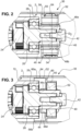
- Fig. 2 now shows the outbreak B from Fig. 1 in an enlarged view.
- the clutch unit 30 can be seen, which is mounted on the output shaft 26.
- the clutch unit 30 has a hub 40, which is mounted against the output shaft 26 by means of a screw 42.
- the output shaft 26 has a blind hole 44, which is provided with an internal thread.
- the hub 40 lies with a front end 46 against the roller bearing 28 when it is fixed axially on the output shaft 26 with the screw 42, as in the embodiment shown.
- the hub 40 has a substantially cylindrical basic shape which is provided with radial projections 48a, 48b.
- a coupling bushing 50 is provided which is formed in one piece.
- the coupling bushing 50 has an output section 52 which in this embodiment is connected at certain points in a frictionally engaged manner to the inner circumferential surface 12 of the roller body in order to transmit torque.
- the coupling bushing 50 has a plurality of radial lugs 54 which are in contact with the inner circumferential surface 12.
- the lugs 54 together define a diameter D1 that is slightly larger than the diameter D2, which is the inner diameter of the roller body 2.
- the individual lugs 54 are designed to be slightly springy so that they can be elastically deformed, in particular so that the diameter D1 is reduced.
- the coupling bushing 50 can be arranged axially in the interior 14 of the roller body 2, with the lugs 54 elastically exerting a radial force on the inner circumferential surface 12, so that a frictional connection between the coupling bushing 50 and the roller body 2 is achieved.
- the coupling bushing 50 further comprises a web 56 which extends radially at an axial end of the output section 52, but has a diameter which is smaller than the diameter D2.
- the web 56 is not used for torque transmission, but solely for positioning the coupling bushing 50.
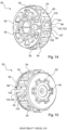
- FIG. 3 an embodiment of the invention is shown. Identical and similar elements are provided with the same reference numerals, and in this respect reference is made in full to the above description. Fig. 2 and 1 reference is made.
- Fig. 3 also exhibits outbreak B Fig. 1 , in which case a different coupling bushing 50 is used.
- the coupling bushing 50 sits on the hub 40, which in turn is constructed like the hub 40 according to the first example ( Fig. 2 ) is provided with radial projections 48c, 48d.
- the coupling bush 50 is in two parts and is mounted with reference to the Fig. 10 and 11 will be explained in more detail.
- the coupling bushing 50 has a radially outer part 60 and a radially inner part 62, wherein the radially inner part 62 is made of a flexible material, in particular a plastic or elastomer.
- the outer part 60 has the output section 52, which according to this exemplary embodiment is designed as an axially extending collar.
- the collar 64 of the output section 52 is made of a thin-walled sheet metal material, which in particular has a smaller thickness than the roller body 2. According to this exemplary embodiment, the thickness of the collar 64 is approximately half the thickness of the roller body 2, in particular 40%, 30% or less.
- the coupling bushing 50 is connected to the roller body 2 via a material connection.
- several welding points 66a, 66b are provided, which connect the collar 64 to the inner circumferential surface 12 of the roller body 2.
- the individual welding points 66a, 66b can be formed axially slightly offset from an axial front end of the collar 64, as shown in the case of welding point 66a, or directly at the axial end, as shown in the case of welding point 66b. In this way, manufacturing tolerances and manufacturing inaccuracies of the collar 64 and the roller body 2 can be compensated for.
- the collar 64 is made of a relatively thin sheet metal material and can therefore also be easily compressed radially.
- the coupling bushing 50 to be inserted, even if the collar 64 is slightly larger than the diameter of the roller body 2.
- the collar 64 is made of a relatively thin sheet material, it is not able to provide a sufficient force-fitting press connection between the coupling bushing 50 and the roller body 2. In order to transmit torque, the collar 64 is therefore materially connected to the roller body 2 at a plurality of individual welding points.
- a laser device is preferably positioned from the outside at the pipe end and the laser beam is directed to the desired Places inside the pipe are focused in order to selectively melt the components to be joined.
- Fig. 2 and the embodiment of the Fig. 3 can also be combined and only their structure initially in the Fig. 2 and 3 represent various alternatives. It is also preferred to additionally connect the individual lugs 54 to the inner circumferential surface 12 of the roller body 2 via welding points 66a, 66b in order to achieve an even more effective torque transmission.
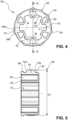
- Fig. 4 shows first a coupling bushing 50, as it is basically also shown in the example according to the Fig. 1 and 2 is installed.
- Fig. 5 shows the cross section AA from Fig. 4 , and in the following both figures will be discussed equally.
- the coupling bushing 50 has an output section 52 and a plurality of radial lugs 54 arranged thereon.
- a total of seven lugs 54 (in Fig. 4 only two are provided with reference numerals) evenly distributed around the circumference.
- the lugs 54 together define a diameter D1 (see Fig. 5 ), which is slightly larger than the diameter D2 of the roller body 2.
- the lugs 54 have a cross-section (cf. Fig. 4 ) have a spherical profile and have two essentially flat flanks 68a, 68b and a round tip 70. Due to this design, the noses 54 are somewhat elastic overall in that they can expand in the circumferential direction through radial compression. This makes it possible to compensate for tolerances and still produce a good frictional connection between the coupling bushing 50 and the roller body 2.
- the lugs 54 also have spherical insertion surfaces 72a, 72b, so that the coupling bushing 50 can easily be joined in the axial direction into the interior 14 of the roller body 2.
- the coupling bush 50 has a central recess 74, which is designed as a through-hole. By means of this recess 74, the coupling bush 50 can be pushed onto the hub 40 in the axial direction.
- the inner circumferential surface 76 of the central recess 74 has a contour which provides a positive Connection in the direction of rotation between the hub 40 and the coupling sleeve 50 is permitted.
- a plurality of projections 78 and recesses 80 are provided on the central recess 74 (in Fig. 4 only one of them is provided with a reference number), which are evenly distributed around the circumference of the central recess 74.
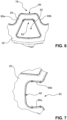
- axial recesses 82 are provided in the area of the projections 78 (cf. Fig. 6 ). These axial recesses 82 have a cross-section perpendicular to the axis of rotation of the coupling bush 50 (i.e. in the plane of the drawing according to Fig. 6 ) has a substantially trapezoidal shape. Its tip 83 corresponds substantially to the contour of the projection 78, so that a wall 84 which separates the axial recess 82 from the central recess 74 in the region of the projections 78 has a substantially constant wall thickness.
- the projections 78 have a concave contour 86 radially inwardly at the tips.
- the lateral flanks 88a, 88b of the projections 78 are essentially radially aligned. This results in the recesses 80 widening slightly radially outwards and opening into a concavely shaped base 90.
- the radial alignment of the lateral flanks 88a, 88b results in the radial projections 48a, 48b on the hub 40 coming into contact flush with the flanks 88a, 88b and a force from the projections 48a, 48b acting essentially perpendicularly on the flanks 88a, 88b.
- the axial recesses 82 lead on the one hand to a weight reduction, on the other hand they explicitly serve the slightly elastic design of the projections 78, which serves to cushion jolts and other load peaks.
- the Fig. 8 and 9 illustrate a second embodiment, which is similar to the first example.
- the coupling bushing 50 is formed in two parts. It has a radially inner part 62 and a radially outer part 60, which forms the output section 52.
- the inner part 62 has a substantially cylindrical peripheral surface 92, on which the outer part 60 is applied in the form of a corrugated sheet metal strip.
- the corrugated sheet metal strip of the outer part 60 forms a plurality of lugs 54, which in this embodiment are then hollow and define a cavity 94 in the interior. This the elasticity of the lugs 54 is further developed and manufacturing tolerances can be compensated even more effectively.
- Fig. 9 shows a slightly modified embodiment in which not only trapezoidal recesses 82 are formed in the area of the projections 78, but also essentially rectangular axial recesses 96 in the area of the recesses 80. This leads to a further reduction in weight and also to a further elastic design of the coupling bushing 50.
- the hub 40 has an inner hub part 41, which is preferably made of a substantially rigid material, such as wear-resistant plastic such as polyamide.
- the inner hub part 41 has a central recess 43, via which the hub 40 can be connected to the corresponding section of the output shaft 26.
- the central recess 43 has a first section 43a with an internal polygon, and a stop ring 43b.
- the internal polygon cooperates with the corresponding external polygon of the output shaft 26 for torque transmission.
- the stop ring 43b is used for axial positioning.
- the hub 40 further comprises an outer part 45 which radially and circumferentially surrounds the inner part 41 and is preferably formed from a flexible material, such as in particular an elastomer material.
- the outer part 41 defines the projections 48a, 48b, 48c, 48d (in the Figures 10 and 11 not all projections are provided with a reference number).
- the projections 48a, 48b, 48c, 48d are each supported by a web 47a, 47b, 47d which is formed on the inner part 41 and extends radially therefrom.
- the webs 47a, 47b, 47d provide reinforcement for the projections 48a, 48b, 48c, 48d.
- the projections 48a, 48b, 48c, 48d each have a radial tongue 49a, 49b, 49d, which together define a collar having a diameter D 4 that is larger than the diameter D 3 of the projections 48a, 48b, 48c, 48d.
- the purpose of the tongues 49a, 49b, 49d is to prevent the hub 40 from "wandering out” during operation if it is not secured by a screw 42.
- the hub 40 is arranged with the section 43a on the output shaft 26.
- the coupling bush 50 is then pushed on and then lies with its drive facing end face to the tongues 49a, 49b, 49d.
- the drive and coupling bushing 50 are in turn axially fixed; the drive via the end cap 4 and the coupling bushing 50 via its connection to the roller body 2. This also axially fixes the hub 40 and prevents it from "wandering out", even though it has a loose bearing and is not clamped by a screw 42.
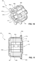
- the Fig. 12 and 13 illustrate another embodiment of the coupling bushing as shown in Fig. 3
- the coupling bushing is shown in the Fig. 12 and 13 is again in two parts and has an inner part 62 and an outer part 60.
- the inner part 62 is made of a plastic or elastomer material to compensate for a jolt or other load peaks.
- the output section 52 is here, as already mentioned with reference to Fig. 3 described, is designed as a collar 64 which extends away from a section 98 which encases the inner part 62. While the section 98 forms a radially outer shell for the flexible inner part 62, the collar 64 is made of a relatively thin sheet metal material which can be easily connected to the roller body 2 by means of spot welding.
- the axial extension of the collar 64 serves on the one hand to keep the collar 64 flexible in order to be able to both expand and contract radially in order to compensate for manufacturing tolerances. On the other hand, this also provides a spatial distance between the welding points and the inner part 62 in order to avoid heating of the flexible inner part 62. The use of laser spot welding further increases this effect.
- the inner part 62 has, according to the first embodiments, a central recess 74 which has an inner contour 76 which is approximately star-shaped. This contour 76 also has projections 78 and recesses 80 which are equally distributed around the circumference. The alternating recesses 80 and projections 78 serve to allow a positive force transmission and torque transmission from the hub 40 to the coupling bushing 50.
- FIGS. 14 and 15 show a further embodiment of the coupling bushing 50.
- this embodiment is similar to the second third embodiment ( Fig. 8 ) and the coupling bushing 50 is formed in two parts with a radially outer part 60, which defines the output section 52, and a radially inner part 62.
- the radially outer part 60 is in turn formed as a corrugated sheet metal strip which sits on a substantially cylindrical peripheral surface 92 of the radially inner part 62.
- the corrugated sheet metal strip has a radial gap 99 which is delimited by a first end section 104 and a second end section 105. This gap 99 is also present in the sheet metal strip of the third embodiment ( Fig. 8 ). It serves to adapt the sheet metal strip more easily to the diameter of the radially inner part 62.
- the radially inner part 62 has, as already seen from the first embodiment ( Fig. 5 ), has a web 56 which has a larger diameter than the peripheral surface 92 and thus serves for the axial positioning of the radially outer part 60.
- an anti-twist device 100 is provided.
- the anti-twist device 100 has a stop 102 against which one of the first and second end sections 104, 105 can strike.
- the stop 102 sits within the gap 99, but has a smaller circumferential extent, so that a certain rotation of the radially outer part 60 is permitted until the first or second end section 104, 105 comes into contact with the stop 102.
- Circumferential front sides 106, 107 (cf. Fig. 14 ) of the stop 102 are radially aligned so that they provide a flat contact surface for the end sections 104, 105. This provides a secure contact that can prevent the radially outer part 60 from coming loose and axially moving away from the web 56.
- the diameter or radial extent of the stop 102 is equal to or less than that of the web 56 to enable easy assembly.
- stop 102 instead of the stop 102, however, a purely material-locking anti-twisting device is also conceivable, for example by providing one or more welding points to connect the sheet metal strip to the peripheral surface 90.
- the hub 40 of the Fig. 10 The recesses 82 are in this embodiment ( Fig. 14, 15 ) are designed as blind hole-like recesses, so that the axial front side in Fig. 15 appears closed. This saves material (mass inertia/costs) and allows for almost constant wall thicknesses to be achieved, which is advantageous for cast/injection-molded parts.
Landscapes
- Engineering & Computer Science (AREA)
- General Engineering & Computer Science (AREA)
- Mechanical Engineering (AREA)
- Rolls And Other Rotary Bodies (AREA)
- Rollers For Roller Conveyors For Transfer (AREA)
Description
Die Erfindung betrifft eine motorbetriebene Förderrolle für Förderanlagen zum Fördern von Behältern, Paletten und dergleichen, mit einem Rollenkörper, dessen Außenumfangsfläche eine Auflagefläche für Fördergut darstellt, eine Antriebseinheit, die innerhalb eines Innenraumes des Rollenkörpers angeordnet ist, und einer zur Übertragung eines Drehmoments von der Antriebseinheit auf eine Innenumfangsfläche des Innenraumes des Rollenkörpers ausgebildete Kupplungseinheit, welche eine Kupplungsbuchse aufweist, die einen Antriebsabschnitt, der mit der Antriebseinheit in Verbindung steht, und einen äußeren peripheren Abtriebsabschnitt aufweist.The invention relates to a motor-driven conveyor roller for conveyor systems for conveying containers, pallets and the like, with a roller body, the outer peripheral surface of which represents a support surface for conveyed material, a drive unit which is arranged within an interior of the roller body, and a coupling unit designed to transmit a torque from the drive unit to an inner peripheral surface of the interior of the roller body, which coupling unit has a coupling bushing which has a drive section which is connected to the drive unit and an outer peripheral output section.
Motorbetriebene Förderrollen dieser Bauart werden für unterschiedliche Zwecke in logistischen Anwendungen eingesetzt. So können sie beispielsweise in der Palettenförderung, bei der Förderung von Paketen in Paketversandzentren, zur Förderung von Behältern in Lagern unterschiedlicher Art oder zum Gepäcktransport in Flughäfen und in zahlreichen anderen Anwendungen eingesetzt werden. Dabei werden solche motorbetriebenen Förderrollen regelmäßig in Förderstrecken eingesetzt, die aus mehreren nebeneinander angeordneten Rollen bestehen, deren obere Umfangsfläche jeweils zur Aufnahme des Förderguts dient. In diesen Förderstrecken sind einerseits Leerlaufrollen angeordnet, die antriebslos sind und lediglich in einem Fördergestell drehbar gelagert sind. Weiterhin sind in diesen Förderstrecken angetriebene Förderrollen angeordnet, die motorbetrieben sind und durch eine elektrische Antriebseinheit in Rotation versetzt werden. Diese motorbetriebenen Förderrollen sind solcherart aufgebaut, dass die Antriebseinheit innerhalb der Rolle selbst angeordnet ist, sodass keine außerhalb des Rollenkörpers angeordneten mechanischen Komponenten erforderlich sind, um die Rotation der Rolle zu erzeugen. Die motorbetriebenen Förderrollen dienen einerseits dazu, unmittelbar über die äußere Umfangsfläche ihres Rollenkörpers das Fördergut zu transportieren, andererseits können mittels einer Übertragung der Rotation der motorbetriebenen Förderrolle auf eine oder mehrere Leerlaufrollen mittels eines Übertragungselementes, beispielsweise eines Riemenantriebs, durch die motorbetriebene Förderrolle auch die Leerlaufrollen in Rotation versetzt werden, um auch über deren äußere Umfangsfläche das Fördergut anzutreiben.Motor-driven conveyor rollers of this type are used for various purposes in logistics applications. For example, they can be used in pallet conveying, in conveying packages in parcel shipping centers, for conveying containers in warehouses of various types or for luggage transport in airports and in numerous other applications. Such motor-driven conveyor rollers are regularly used in conveyor lines that consist of several rollers arranged next to one another, the upper circumferential surface of which serves to hold the goods being conveyed. On the one hand, idle rollers are arranged in these conveyor lines, which are driveless and are only rotatably mounted in a conveyor frame. In addition, driven conveyor rollers are arranged in these conveyor lines, which are motor-driven and are set in rotation by an electric drive unit. These motor-driven Conveyor rollers are designed in such a way that the drive unit is arranged inside the roller itself, so that no mechanical components arranged outside the roller body are required to generate the rotation of the roller. The motor-driven conveyor rollers serve on the one hand to transport the material to be conveyed directly via the outer circumferential surface of their roller body, and on the other hand, by transferring the rotation of the motor-driven conveyor roller to one or more idle rollers by means of a transmission element, for example a belt drive, the motor-driven conveyor roller can also set the idle rollers in rotation in order to drive the material to be conveyed via their outer circumferential surface.
Aus
Bei dieser Art hat sich gezeigt, dass die Geräuschentwicklung hoch sein kann. Daher wurde eine demgegenüber verbesserte Förderrolle in
Zwar haben sich beide Lösungen als gut geeignet zur Übertragung von Drehmomenten herausgestellt, allerdings besteht ein Problem darin, dass insbesondere bei schwankenden Toleranzen die Vorspannung zu hoch sein kann, sodass sich an der Außenfläche des Rollenkörpers eine Auswölbung ergibt. Dies ist im Betrieb von Rollen höchst unerwünscht.Although both solutions have proven to be well suited to transmitting torque, one problem is that the preload can be too high, particularly with fluctuating tolerances, resulting in a bulge on the outer surface of the roller body. This is highly undesirable when rollers are in operation.
Darüber hinaus besteht ein Problem bei geschmierten motorbetriebenen Förderrollen darin, dass der Reibschluss durch einen Ölfilm verschlechtert werden kann. Zwar ist es möglich bei bzw. vor der Montage den Rollenkörper von innen zu reinigen, aber eine dauerhafte Ölfreiheit auch im Betrieb kann so nicht erreicht werden.Another problem with lubricated motor-driven conveyor rollers is that the frictional connection can be impaired by an oil film. Although it is possible to clean the roller body from the inside during or before assembly, this cannot ensure that it is permanently free of oil during operation.
Weiterhin wurde gemäß
Aufgrund des formschlüssigen Eingriffs zwischen Antrieb und Rollenkörper wird zwar das Problem des Verformens des Rollenkörpers aufgrund einer überhöhten Pressung vermieden, allerdings ist die Konstruktion sehr aufwendig. Zudem müssen bei der Fertigung enge Toleranzen eingehalten werden, wodurch Kosten verursacht werden. Ferner ergibt sich auch bei der Wartung ein Problem, nämlich dann, wenn die formschlüssige Verbindung defekt ist. Bei einer klemmenden Verbindung, wie sie ebenfalls aus dem Stand der Technik bekannt ist, kann hier einfach nachgestellt werden, wohingegen bei der formschlüssigen Verbindung ein Austausch der Teile erforderlich ist.Due to the positive engagement between the drive and the roller body, the problem of the roller body deforming due to excessive pressure is avoided, but the design is very complex. In addition, tight tolerances must be maintained during production, which incurs costs. There is also a problem with maintenance, namely when the positive connection is defective. In the case of a clamping connection, as is also known from the state of the art, this can be easily adjusted, whereas with a positive connection the parts must be replaced.
Aus dem europäischen Prüfungsverfahren ist ferner folgender Stand der Technik bekannt:
Aufgabe der vorliegenden Erfindung ist es daher, eine Förderrolle der eingangs genannten Art anzugeben, die bezüglich der Konstruktion vereinfacht ist und bei der eine sichere Drehmomentenübertragung von dem Antrieb auf die Förderrolle auch bei weiten Toleranzen ohne Verformung des Rollenkörpers möglich ist.The object of the present invention is therefore to provide a conveyor roller of the type mentioned at the outset, which is simplified in terms of construction and in which a reliable torque transmission from the drive to the conveyor roller is possible even with wide tolerances without deformation of the roller body.
Die Aufgabe wird durch eine motorbetriebene Förderrolle gemäß Anspruch 1 gelöst. Ferner wird die Aufgabe durch eine motorbetriebene Förderrolle nach Anspruch 13 gelöst.The object is achieved by a motor-driven conveyor roller according to claim 1. Furthermore, the object is achieved by a motor-driven conveyor roller according to claim 13.
In Abkehr vom Stand der Technik, bei dem einerseits eine umfängliche reibschlüssige Verbindung vorgesehen war oder andererseits eine formschlüssige Verbindung, schlägt die vorliegende Erfindung vor, eine punktuelle reibschlüssige Verbindung oder eine punktuelle stoffschlüssige Verbindung zu verwenden. Sowohl reibschlüssige als auch stoffschlüssige Verbindungen sind in der Konstruktion gegenüber formschlüssigen wesentlich vereinfacht. Sie lassen gegenüber formschlüssigen Verbindungen wesentlich höhere Toleranzen zu, wodurch die Fertigungskosten verringert sind. Eine punktuelle reibschlüssige Verbindung ist gegenüber einer umfänglichen reibschlüssigen Verbindung ebenfalls vereinfacht, da auch diese höhere Toleranzen zulässt. Dadurch wird das Problem einer überhöhten Pressung aufgrund von mangelnden Toleranzen vermieden und die Fertigung so insgesamt vereinfacht und die Förderrolle kostengünstiger herstellbar.In a departure from the prior art, in which a circumferential frictional connection was provided on the one hand or a positive connection on the other, the present invention proposes using a point-based frictional connection or a point-based material-fit connection. Both frictional and material-fit connections are significantly simpler in construction than positive connections. They allow significantly higher tolerances than positive connections, which reduces manufacturing costs. A point-based frictional connection is also simpler than a circumferential frictional connection, as this also allows higher tolerances. This avoids the problem of excessive pressure due to insufficient tolerances, thus simplifying production overall and making the conveyor roller more cost-effective to manufacture.
Eine punktuelle reibschlüssige Verbindung, wie sie die Erfindung vorschlägt hat darüber hinaus den Vorteil, dass auf der Innenumfangsfläche des Rollenkörpers vorhandenes Öl leichter verdrängt werden kann. Es ist also erfindungsgemäß möglich auch bei ölgeschmierten Förderrollen eine wirksame reibschlüssige Verbindung zu erzielen, ohne dass eine aufwändige Entfettung durchgeführt wird, oder der Reibschluss im Betrieb nachlässt.A point-based frictional connection, as proposed by the invention, also has the advantage that oil present on the inner circumferential surface of the roller body can be displaced more easily. According to the invention, it is therefore possible to achieve an effective frictional connection even with oil-lubricated conveyor rollers, without the need for complex degreasing or the frictional connection decreasing during operation.
Der Erfindung liegt die Erkenntnis zugrunde, dass bei motorbetriebenen Förderrollen keine sehr hohen Momente übertragen werden müssen und daher auch eine punktuelle reibschlüssige Verbindung im Gegensatz zu einer umfänglichen reibschlüssigen Verbindung, die eine wesentlich höhere Fläche für die Momentenübertragung bereitstellt, ausreichend ist. Hierdurch lässt sich der Vorteil der punktuellen reibschlüssigen Verbindung, insbesondere das Ausgleichen von Fertigungstoleranzen, nutzen, wodurch die Fertigung vereinfacht ist. Einen ähnlichen Vorteil bietet auch die stoffschlüssige Verbindung, da auch diese Fertigungstoleranzen ausgleichen kann, wenn sie punktuell ausgebildet ist. Daher sind beide Varianten gleichermaßen bevorzugt und lösen dasselbe Problem.The invention is based on the knowledge that very high torques do not have to be transmitted with motor-driven conveyor rollers and that a point-based frictional connection is therefore sufficient in contrast to a comprehensive frictional connection, which provides a much larger area for torque transmission. This allows the advantage of the point-based frictional connection, in particular the compensation of manufacturing tolerances, which simplifies production. A similar advantage is offered by the material-to-material connection, as this can also compensate for manufacturing tolerances if it is formed at specific points. Therefore, both variants are equally preferred and solve the same problem.
Gemäß einer ersten bevorzugten Ausführungsform weist der Abtriebsabschnitt der Kupplungsbuchse eine Mehrzahl an radialen Nasen auf, die dazu vorgesehen sind, mit der Innenumfangsfläche des Rollenkörpers in Kontakt zu stehen. Die Nasen bilden auf diese Weise Kontaktpunkte, an denen eine punktuelle reibschlüssige Verbindung zwischen Kupplungsbuchse und Rollenkörper hergestellt wird. Die Nasen sind vorzugsweise im Querschnitt abgerundet ausgebildet und/oder weisen eine leicht trapezförmige Form auf, die am radial äußeren Ende ein leichtes Plateau ausbildet. Die Nasen weisen bevorzugt eine Außenkontur auf, die in etwa teilzylindrisch ist und sich in axialer Richtung wenigstens teilweise, vorzugsweise vollständig, über die Kupplungsbuchse erstreckt.According to a first preferred embodiment, the output section of the coupling bushing has a plurality of radial lugs that are intended to be in contact with the inner circumferential surface of the roller body. In this way, the lugs form contact points at which a point-by-point frictional connection is established between the coupling bushing and the roller body. The lugs are preferably rounded in cross-section and/or have a slightly trapezoidal shape that forms a slight plateau at the radially outer end. The lugs preferably have an outer contour that is approximately partially cylindrical and extends at least partially, preferably completely, over the coupling bushing in the axial direction.
Vorzugsweise definieren die radialen Nasen gemeinsam einen Durchmesser, der größer ist als der Durchmesser der Innenumfangsfläche. Hierdurch wird eine besonders gute reibschlüssige Verbindung zwischen Kupplungsbuchse und Rollenkörper erreicht, da die Nasen gemeinsam ein Übermaß definieren und die Kupplungsbuchse so unter Vorspannung in den Rollenkörper eingesetzt ist.Preferably, the radial lugs together define a diameter that is larger than the diameter of the inner circumferential surface. This achieves a particularly good frictional connection between the coupling bushing and the roller body, since the lugs together define an oversize and the coupling bushing is thus inserted into the roller body under pre-tension.
Hierzu sind die Nasen vorzugsweise nachgiebig ausgebildet. Eine nachgiebige Ausbildung der Nasen begrenzt die radial wirkende Kraft, die von der Kupplungsbuchse auf den Rollenkörper wirkt, wodurch ein Verformen des Rollenkörpers effektiv vermieden werden kann.For this purpose, the lugs are preferably designed to be flexible. A flexible design of the lugs limits the radial force that acts from the coupling bushing on the roller body, which can effectively prevent deformation of the roller body.
Vorzugsweise sind die Nasen innerlich hohl ausgebildet. Hierdurch ist es möglich, die Nasen radial zu stauchen, um so eine Nachgiebigkeit zu erzielen. Die Nasen können beispielsweise als Blechabschnitte ausgebildet sein, die federnd wirken, um in radialer Richtung eine Anpresskraft auf den Rollenkörper auszuüben, um so eine reibschlüssige Verbindung zwischen Kupplungsbuchse und Rollenkörper zu erzeugen. Insbesondere bei diesem Aspekt ist bevorzugt, dass die Nasen eine bekannte Federkonstante aufweisen, die vordefiniert eingestellt ist. Hierdurch ist es möglich, auch bei gewissen Toleranzabweichungen eine in einem definierten Bereich liegende radiale Anpresskraft vorzusehen, die hoch genug ist, um eine Drehmomentenübertragung von der Kupplungsbuchse auf den Rollenkörper zu erreichen, Öl zu verdrängen, aber gleichzeitig ein Verformen des Rollenkörpers zu vermeiden.The lugs are preferably hollow on the inside. This makes it possible to compress the lugs radially in order to achieve flexibility. The lugs can, for example, be designed as sheet metal sections that act in a springy manner in order to exert a contact force on the roller body in the radial direction in order to create a frictional connection between the coupling bushing and the roller body. In this aspect in particular, it is preferred that the lugs have a known spring constant that is predefined. This makes it possible to provide a radial contact force within a defined range, even with certain tolerance deviations, which is high enough to achieve a torque transfer from the coupling bushing to the roller body, to displace oil, but at the same time to avoid deformation of the roller body.
Gemäß einer weiteren bevorzugten Ausführungsform ist der Abtriebsabschnitt mit der Innenumfangsfläche des Rollenkörpers verschweißt. Erfindungsgemäß ist diese Verschweißung nur an bestimmten Punkten vorgesehen, um die punktuell wirkende stoffschlüssige Übertragung von Drehmomenten von der Kupplungsbuchse auf den Rollenkörper zu ermöglichen. Vorzugsweise ist der Abtriebsabschnitt mittels Punktschweißen mit der Innenumfangsfläche des Rollenkörpers verbunden. Rollenkörper sind üblicherweise mit einer Zinkschicht versehen, die bei hohem Wärmeeintrag beschädigt wird. Beim Punktschweißen ist der Wärmeeintrag sehr gering. Hierdurch wird ein stoffschlüssiges Verbinden der Kupplungsbuchse mit dem Rollenkörper ermöglicht, ohne die Gefügetopologie oder die visuelle Erscheinung der Verzinkung an der Außenseite des Rollenkörpers zu verändern. Dies wird insbesondere durch den minimalen Energie- und somit Wärmeeintrag während einer Punktschweißung erreicht. Bevorzugt ist insbesondere Laser-Punkt-Schweißen, da hierbei der Energie- und Wärmeeintrag besonders gering gehalten werden kann.According to a further preferred embodiment, the output section is welded to the inner circumferential surface of the roller body. According to the invention, this welding is only provided at certain points in order to enable the point-acting, material-locking transfer of torque from the coupling bush to the roller body. The output section is preferably connected to the inner circumferential surface of the roller body by means of spot welding. Roller bodies are usually provided with a zinc layer, which is damaged by high heat input. With spot welding, the heat input is very low. This enables a material-locking connection of the coupling bush to the roller body without changing the structure topology or the visual appearance of the galvanization on the outside of the roller body. This is achieved in particular by the minimal energy and thus heat input during spot welding. Laser spot welding is particularly preferred, since the energy and heat input can be kept particularly low here.
Beispielsweise ist eine Punktschweißverbindung im Bereich der radialen Nasen vorgesehen. Aufgrund der Vorspannung liegen die radialen Nasen permanent an der Innenumfangsfläche an, sodass sich diese Abschnitte besonders für die stoffschlüssige Verbindung mittels Punktschweißen eignen. Auch bei gewissen Maßabweichungen ist an diesen Abschnitten eine gute Anlage zwischen Kupplungsbuchse und Innenumfangsabschnitt erreicht, die ein Punktschweißen erlaubt.For example, a spot weld connection is provided in the area of the radial lugs. Due to the pre-tension, the radial lugs are permanently in contact with the inner circumferential surface, so that these sections are particularly suitable for the material-fit connection by means of spot welding. Even with certain dimensional deviations, a good contact between the coupling bushing and the inner circumferential section is achieved in these sections, which allows spot welding.
In einer weiteren bevorzugten Ausführungsform sind um einen Umfang des Abtriebsabschnitts 3 bis 20, vorzugsweise 5 bis 15, besonders bevorzugt 7 bis 10 separate Verbindungspunkte vorgesehen, an denen die Kupplungsbuchse punktuell mit der Innenumfangsfläche des Rollenkörpers verbunden ist. Es hat sich herausgestellt, dass eine Anzahl im Bereich von 3 bis 20 und besonders bevorzugt 7 bis 10 Verbindungspunkten ausreichend ist, um eine gute Drehmomentenübertragung zu erzielen und gleichzeitig auch axial, senkrecht auf die Rotationsachse des Rollenkörpers wirkende Kräfte aufzunehmen. Bezogen auf die oben beschriebene bevorzugte Ausführungsform bedeutet dies, dass 3 bis 20 Nasen und/oder 3 bis 20 Schweißpunkte vorgesehen sind. Die einzelnen separaten Verbindungspunkte sind vorzugsweise gleichmäßig um den Umfang verteilt. Die genaue Anzahl ist abhängig von den zu übertragenden Drehmomenten und auch dem Durchmesser des Rollenkörpers zu bestimmen.In a further preferred embodiment, 3 to 20, preferably 5 to 15, particularly preferably 7 to 10 separate connection points are provided around the circumference of the output section, at which the coupling bushing is connected at certain points to the inner circumferential surface of the roller body. It has been found that a number in the range of 3 to 20 and particularly preferably 7 to 10 connection points is sufficient to achieve good torque transmission and at the same time to absorb forces acting axially, perpendicular to the rotation axis of the roller body. In relation to the preferred embodiment described above, this means that 3 to 20 lugs and/or 3 to 20 welding points are provided. The individual separate connection points are preferably evenly distributed around the circumference. The exact number is determined depending on the torques to be transmitted and also the diameter of the roller body.
Gemäß der Erfindung ist vorgesehen, dass die Kupplungsbuchse zwei- oder mehrteilig ist und ein radial äußeres Teil aufweist, welches den Abtriebsabschnitt bildet, und ein radial inneres Teil, welches einen Teil einer Welle-Nabe-Verbindung bildet und mit einer Abtriebswelle des Antriebs verbunden ist, auf. Indem das innere Teil einen Teil einer Welle-Nabe-Verbindung bildet, ist es besonders einfach mit der Abtriebswelle des Antriebs verbindbar. Beispielsweise weist die Abtriebswelle des Antriebs ein Mehrkantprofil auf, und das innere Teil der Kupplungsbuchse weist einen Innenmehrkant auf, der mit dem Außenmehrkant der Abtriebswelle des Antriebs korrespondiert. Weitere bevorzugte Welle-Nabe-Verbindungen sind Nut-Passfeder-Verbindungen, Klemmverbindungen und dergleichen. Auch eine gezahnte Verbindung ist denkbar und bevorzugt. Vorzugsweise ist in dieser Ausführungsform das innere Teil mit dem äußeren Teil verbunden, um so eine Drehmomentenübertragung von dem inneren Teil auf das äußere Teil zu gewährleisten. Es kann vorgesehen sein, dass das innere und das äußere Teil elastisch miteinander verbunden sind, um einen Antriebsruck, andere Stöße oder Schwingungen auszugleichen.According to the invention, the coupling bushing is in two or more parts and has a radially outer part, which forms the output section, and a radially inner part which forms part of a shaft-hub connection and is connected to an output shaft of the drive. As the inner part forms part of a shaft-hub connection, it is particularly easy to connect to the output shaft of the drive. For example, the output shaft of the drive has a polygonal profile, and the inner part of the coupling bush has an inner polygon which corresponds to the outer polygon of the output shaft of the drive. Other preferred shaft-hub connections are keyway connections, clamp connections and the like. A toothed connection is also conceivable and preferred. Preferably, in this embodiment, the inner part is connected to the outer part in order to ensure torque transmission from the inner part to the outer part. It can be provided that the inner and outer parts are elastically connected to one another in order to compensate for drive jolts, other shocks or vibrations.
Das radial äußere Teil ist in einer bevorzugten Ausführungsform als gewellter Blechstreifen, in einer besonders bevorzugten Ausführungsform aus einem Federstahl ausgebildet. Ein solcher gewellter Blechstreifen kann beispielsweise auf einer im Wesentlichen zylindrischen Umfangsfläche des inneren Teils aufgesetzt sein. Vorzugsweise ist das radial äußere Teil vorgespannt auf die Umfangsfläche aufgesetzt und im in den Rollenkörper eingepressten Zustand derart verpresst, dass das radial äußere Teil sowohl mit der Umfangsfläche des inneren Teils als auch mit dem Rollenkörper reibschlüssig verbunden ist, um ein Drehmoment von dem radial inneren Teil über das radial äußere Teil auf den Rollenkörper übertragen zu können.In a preferred embodiment, the radially outer part is designed as a corrugated sheet metal strip, in a particularly preferred embodiment from a spring steel. Such a corrugated sheet metal strip can, for example, be placed on a substantially cylindrical peripheral surface of the inner part. The radially outer part is preferably placed on the peripheral surface in a pre-stressed manner and, when pressed into the roller body, is pressed in such a way that the radially outer part is frictionally connected to both the peripheral surface of the inner part and the roller body in order to be able to transmit a torque from the radially inner part to the roller body via the radially outer part.
Zusätzlich hierzu ist es auch bevorzugt eine beispielsweise formschlüssige Verdrehsicherung zum Sichern des radial äußeren Teils gegen Rotation relativ zum radial inneren Teil vorzusehen. Eine solche Verdrehsicherung kann eine gewisse Rotation erlauben, solange sie nach einer bestimmten Drehung (insbesondere wenigen Grad) greift und die weitere Drehung verhindert. Die Verdrehsicherung soll insbesondere dann greifen, wenn eine reibschlüssige Verbindung zwischen innerem und äußerem Teil nicht ausreicht, beispielsweise bei hohen zu übertragenden Drehmomenten.In addition to this, it is also preferred to provide a positive-locking anti-twisting device, for example, to secure the radially outer part against rotation relative to the radially inner part. Such an anti-twisting device can allow a certain amount of rotation as long as it takes effect after a certain rotation (in particular a few degrees) and prevents further rotation. The anti-twisting device should take effect in particular when a frictional connection between the inner and outer parts is not sufficient, for example when high torques are to be transmitted.
In einer Ausführungsform ist die Verdrehsicherung als Anschlag ausgebildet, gegen den ein umfänglicher Endabschnitt des radial äußeren Teils anschlägt. Die Verdrehsicherung wirkt in diesem Fall formschlüssig. Alternativ oder zusätzlich ist auch eine stoffschlüssig wirkende Verdrehsicherung denkbar und bevorzugt. Beispielsweise kann das radial äußere Teil mittels eines oder mehrerer Schweißpunkte an dem radial inneren Teil befestigt werden. Auch ist denkbar, dass das radial äußere Teil mittels einer Verstiftung mit dem radial inneren Teil formschlüssig verbunden ist.In one embodiment, the anti-twisting device is designed as a stop against which a circumferential end section of the radially outer part strikes. In this case, the anti-twisting device acts in a form-fitting manner. Alternatively or additionally, an anti-twisting device acting in a material-fitting manner is also conceivable and preferred. For example, the radially outer part can be attached to the radially inner part by means of one or more welding points. It is also conceivable that the radially outer part is positively connected to the radially inner part by means of a pin.
Gemäß der Erfindung ist vorgesehen, dass das radial innere Teil aus einem flexiblen Material, insbesondere einem Elastomermaterial gebildet ist. Hierdurch ist die Welle-Nabe-Verbindung zwischen dem inneren Teil und der Abtriebswelle des Antriebs in Drehrichtung elastisch, sodass ein Ruck oder andere Belastungen abgefedert werden können. Ein weiterer Vorteil ist auch hierbei die Fertigungstoleranz, da elastische Bauteile durch ihre Materialeigenschaften Fertigungstoleranzen besser ausgleichen können als starre Elemente.According to the invention, the radially inner part is made of a flexible material, in particular an elastomer material. This makes the shaft-hub connection between the inner part and the output shaft of the drive elastic in the direction of rotation, so that a jolt or other loads can be cushioned. Another advantage here is the manufacturing tolerance, since elastic components can compensate for manufacturing tolerances better than rigid elements due to their material properties.
In einer vorteilhaften Ausgestaltung ist die Kupplungsbuchse bezogen auf die Antriebseinheit axial verschieblich gelagert. Bevorzugt ist auch die Nabe axial verschieblich gelagert. Es ist vorzugsweise keine zusätzliche axiale Fixierung, wie etwa eine stirnseitige Schraube zur Fixierung der Nabe vorgesehen. Bevorzugt ist wenigstens die Nabe mittels eines axialen Loslagers auf der Abtriebswelle des Antriebs gelagert, oder die Kupplungsbuchse ist mittels eines axialen Loslagers auf der Nabe gelagert. Hierdurch wird eine axiale Relativverschiebung zwischen Kupplungsbuchse und Antriebseinheit erlaubt. Dies ist einerseits bevorzugt, um Toleranzen auszugleichen, andererseits wird dies durch die Verbindung zwischen Kupplungsbuchse und Rollenkörper ermöglicht.In an advantageous embodiment, the coupling bushing is mounted axially displaceably relative to the drive unit. Preferably, the hub is also mounted axially displaceably. Preferably, no additional axial fixation, such as a front-end screw for fixing the hub, is provided. Preferably, at least the hub is mounted on the output shaft of the drive by means of an axial loose bearing, or the coupling bushing is mounted on the hub by means of an axial loose bearing. This allows an axial relative displacement between the coupling bushing and the drive unit. On the one hand, this is preferred in order to compensate for tolerances, and on the other hand, it is made possible by the connection between the coupling bushing and the roller body.
Gemäß einer weiteren Ausführungsform weist die Kupplungsbuchse eine zentrale Ausnehmung auf, in die eine Abtriebswelle des Antriebs eingesetzt ist, wobei die zentrale Ausnehmung wechselseitig umfänglich sich radial erstreckende Vorsprünge und Ausnehmungen aufweist. Die Ausnehmung kann in dem inneren Teil der Kupplungsbuchse ausgebildet sein und einen Teil der Welle-Nabe-Verbindung bilden. Die Ausnehmung ist vorzugsweise als Durchgangsöffnung ausgebildet. Die zentrale Ausnehmung weist gemäß dieser Ausführungsform im Querschnitt eine im Wesentlichen sternförmige Kontur auf, wodurch weiterhin die Fertigungstoleranzen ausgeglichen werden können. Das innere Teil bzw. die Kupplungsbuchse ist aufgrund der sternförmig ausgebildeten inneren Ausnehmung leicht flexibel und ist somit in der Lage, geringe Fertigungstoleranzen auszugleichen. Ein weiterer Vorteil liegt darin, dass die sternförmige Kontur auch zum formschlüssigen Übertragen von Drehmomenten von der Abtriebswelle des Antriebs auf die Kupplungsbuchse verwendet werden kann.According to a further embodiment, the coupling bushing has a central recess into which an output shaft of the drive is inserted, the central recess having projections and recesses that extend radially around the circumference. The recess can be formed in the inner part of the coupling bushing and form part of the shaft-hub connection. The recess is preferably designed as a through-opening. According to this embodiment, the central recess has a substantially star-shaped contour in cross-section, which also allows the manufacturing tolerances to be compensated. The inner part or the coupling bushing is slightly flexible due to the star-shaped inner recess and is thus able to compensate for small manufacturing tolerances. A further advantage is that the star-shaped contour can also be used for the positive transmission of torque from the output shaft of the drive to the coupling bushing.
In einer bevorzugten Weiterbildung sind die Vorsprünge an den radial innerlichen Spitzen konkav abgeflacht. Hierdurch lässt sich eine Anlage an im Wesentlichen zylindrischen Abschnitten einer Abtriebswelle des Antriebs erreichen.In a preferred development, the projections are concavely flattened at the radially inner tips. This makes it possible to achieve a contact with essentially cylindrical sections of an output shaft of the drive.
Vorzugsweise weist die Kupplungsbuchse im Bereich der radialen Vorsprünge axiale Ausnehmungen auf. Die axialen Ausnehmungen erstrecken sich teilweise in axialer Richtung durch die Kupplungsbuchse, vorzugsweise erstrecken sich die Ausnehmungen vollständig durch die Kupplungsbuchse. Besonders bevorzugt weisen die Ausnehmungen im Querschnitt eine im Wesentlichen trapezförmige Form auf. Vorzugsweise ist der Querschnitt der Ausnehmungen korrespondierend zu dem Querschnitt der Vorsprünge, sodass sich zwischen der Ausnehmung in dem Vorsprung und der zentralen Ausnehmung eine in etwa gleichmäßige Wandstärke ergibt. Durch derartige Ausnehmungen werden eine Gewicht- und Materialeinsparungen erzielt, und die Vorsprünge werden weiter flexibel gebildet und sind in der Lage, einen Ruck oder andere Belastungsspitzen abzufedern.The coupling bushing preferably has axial recesses in the region of the radial projections. The axial recesses extend partially in the axial direction through the coupling bushing, preferably the recesses extend completely through the coupling bushing. Particularly preferably, the recesses have a substantially trapezoidal shape in cross section. Preferably, the cross section of the recesses corresponds to the cross section of the projections, so that an approximately uniform wall thickness results between the recess in the projection and the central recess. Such recesses achieve weight and material savings, and the projections are further flexible and are able to absorb a jolt or other load peaks.
Weiterhin ist bevorzugt, dass die seitlichen Flanken der radialen Vorsprünge im Wesentlichen radial ausgerichtet sind. Hierdurch bieten die Flanken der radialen Vorsprünge Anlageflächen für die Drehmomentenübertragung, und eine Kraft von der Abtriebswelle des Antriebs auf die Kupplungsbuchse wirkt senkrecht auf die Flanke der Vorsprünge, wenn der Antrieb die Kupplungsbuchse antreibt.It is further preferred that the lateral flanks of the radial projections are aligned substantially radially. As a result, the flanks of the radial projections provide contact surfaces for torque transmission, and a force from the output shaft of the drive to the coupling bushing acts perpendicularly on the flank of the projections when the drive drives the coupling bushing.
Erfindungsgemäß weist die Kupplungsbuchse einen sich axial erstreckenden Kragen auf, an dem der Abtriebsabschnitt ausgebildet ist. Der axial sich erstreckende Kragen erstreckt sich axial weg vom inneren Teil und ist vorzugsweise an dem äußeren Teil ausgebildet. Der Kragen weist vorzugsweise einen Durchmesser auf, der größer ist als der Durchmesser des axial benachbarten Abschnitts der Kupplungsbuchse. Auch hierdurch werden Fertigungstoleranzen weiter ausgeglichen. Diese Ausführungsform ist besonders dann bevorzugt, wenn der Abtriebsabschnitt stoffschlüssig mit dem Rollenkörper verbunden wird. Der axial sich erstreckende Kragen kann in diesem Fall aus einem dünnen Blechabschnitt gebildet sein, welcher auf einfache Art und Weise mittels Punktschweißen, insbesondere durch eine Laser-Punkt-Schweißung, mit dem Rollenkörper verbindbar ist.According to the invention, the coupling bushing has an axially extending collar on which the output section is formed. The axially extending collar extends axially away from the inner part and is preferably formed on the outer part. The collar preferably has a diameter that is larger than the diameter of the axially adjacent section of the coupling bushing. This also further compensates for manufacturing tolerances. This embodiment is particularly preferred when the output section is integrally connected to the roller body. The axially extending collar can in this case be formed from a thin sheet metal section that can be connected to the roller body in a simple manner by means of spot welding, in particular by means of laser spot welding.
Nachstehend wird die Erfindung anhand von Ausführungsbeispielen näher erläutert.The invention is explained in more detail below using exemplary embodiments.
Dabei zeigen:
- Fig. 1
- einen Querschnitt durch eine Förderrolle;
- Fig. 2
- einen vergrößerten Querschnitt der Förderrolle aus
Fig. 1 ; - Fig. 3
- einen Querschnitt gemäß
Fig. 2 von einem ersten Ausführungsbeispiel; - Fig. 4
- eine Seitenansicht einer Kupplungsbuchse gemäß dem ersten, nicht beanspruchten, Beispiel;
- Fig. 5
- einen Querschnitt A-A gemäß
Fig. 4 ; - Fig. 6
- das Detail A aus
Fig. 4 ; - Fig. 7
- das Detail B aus
Fig. 4 ; - Fig. 8
- eine perspektivische Ansicht einer Kupplungsbuchse gemäß einem zweiten Ausführungsbeispiel;
- Fig. 9
- eine Seitenansicht einer Kupplungsbuchse gemäß einem dritten Ausführungsbeispiel;
- Fig. 10
- eine perspektivische Ansicht einer Nabe für die Kupplungsbuchsen gemäß
Fig. 2 und4 bis 9 ; - Fig. 11
- einen Schnitt durch die Nabe gemäß
Fig. 10 ; - Fig. 12
- eine perspektivische Ansicht einer Kupplungsbuchse gemäß dem ersten Ausführungsbeispiel;
- Fig. 13
- einen Schnitt durch die Kupplungsbuchse aus
Fig. 12 ; - Fig. 14
- eine perspektivische Ansicht einer Kupplungsbuchse gemäß einem vierten Ausführungsbeispiel samt Nabe gem.
Fig. 10 ; und - Fig. 15
- eine weitere perspektivische Ansicht der Kupplungsbuchse gemäß dem vierten Ausführungsbeispiel.
- Fig. 1
- a cross-section through a conveyor roller;
- Fig. 2
- an enlarged cross-section of the conveyor roller
Fig. 1 ; - Fig. 3
- a cross-section according to
Fig. 2 of a first embodiment; - Fig. 4
- a side view of a coupling bushing according to the first, unclaimed, example;
- Fig. 5
- a cross section AA according to
Fig. 4 ; - Fig. 6
- the detail A from
Fig. 4 ; - Fig. 7
- the detail B from
Fig. 4 ; - Fig. 8
- a perspective view of a coupling bushing according to a second embodiment;
- Fig. 9
- a side view of a coupling bushing according to a third embodiment;
- Fig. 10
- a perspective view of a hub for the coupling bushings according to
Fig. 2 and4 to 9 ; - Fig. 11
- a section through the hub according to
Fig. 10 ; - Fig. 12
- a perspective view of a coupling bushing according to the first embodiment;
- Fig. 13
- a section through the coupling bushing
Fig. 12 ; - Fig. 14
- a perspective view of a coupling bushing according to a fourth embodiment including hub according to.
Fig. 10 ; and - Fig. 15
- another perspective view of the coupling bushing according to the fourth embodiment.
Das Wälzlager 6 dient zur drehbaren Lagerung eines Lagerzapfens 8. Der Lagerzapfen 8 ist an einem nach außen weisenden Ende mit einem Außengewinde versehen, auf dem eine Mutter 10 aufgeschraubt ist und mit Hilfe derer der Lagerzapfen 8 drehmomentenfest in einer Öffnung eines Gestells befestigt werden kann. Das Gestell wird dabei zwischen der Mutter (nicht gezeigt) und einer auf dem Gewinde 10 einwärts von der Mutter festgesetzten Hülse geklemmt.The rolling
Der Rollenkörper 2 weist eine innere Umfangsfläche 12 auf, die einen Innenraum 14 in dem Rollenkörper 2 radial äußerlich begrenzt.The
Der Lagerzapfen 8 ist hohl ausgeführt, und durch die Innenbohrung des Lagerzapfens 8 werden Versorgungs- und Steuerleitungen 16 zu einer im Inneren angeordneten Antriebseinheit 18 geführt. Die Antriebseinheit 18 ist innerhalb des Rollenkörpers 2 angeordnet und drehmomentenfest mit dem Lagerzapfen 8 verbunden. Die Antriebseinheit 18 weist an ihrem zum Lagerzapfen 8 weisenden Ende eine Steuerelektronik 20 zur Ansteuerung eines elektrischen Antriebsmotors 22 auf, der vorzugsweise als bürstenloser, dreiphasiger Gleichstrommotor mit Innenläufer ausgeführt ist. Der Antriebsmotor 22 ist zwischen der Steuerungselektronik 20 und einem Planetengetriebe 24 in der Antriebseinheit 18 angeordnet, welches an dem von dem Lagerzapfen 8 wegweisenden Ende der Antriebseinheit 18 angeordnet ist.The
Das Planetengetriebe 24 weist eine Abtriebswelle 26 auf, die wiederum in einem Rollenlager 28 gelagert ist.The
Zum Übertragen von Drehmomenten von der Abtriebswelle 26 auf den Rollenkörper 2 weist die Förderrolle 1 eine Kupplungseinheit 30 auf, die nachstehend näher erläutert werden wird. Infolge der Übertragung von Drehmomenten von der Abtriebswelle 28 über die Kupplungseinheit 30 auf den Rollenkörper 2 dreht sich der Rollenkörper infolgedessen mit dem Antriebsdrehmoment relativ zu dem Lagerzapfen 8 und der Antriebseinheit 18.To transmit torque from the
An dem dem Lagerzapfen 8 gegenüberliegenden Ende 5 des Rollenkörpers 2 ist ein Kopfstück 32 drehmomentenfest in den Rollenkörper 2 eingesetzt. Dieses Kopfstück 32 trägt mehrere W-förmige Umfangsnuten 34, mittels derer die Rotation und das Drehmoment der Förderrolle 1 auf benachbarte Leerlaufrollen übertragen werden kann. Innerhalb des Kopfstücks 32 ist eine Aufnahme 36 für eine Wälzlagerung für die Lagerung der Förderrolle 1 an einem endseitigen Lagerzapfen (nicht gezeigt) ausgebildet.At the end 5 of the
Radial äußerlich weist die Nabe 40 eine im Wesentlichen zylindrische Grundform auf, die mit radialen Vorsprüngen 48a, 48b versehen ist.Radially outwardly, the
Auf der Nabe 40 (vgl. auch
Genauer gesagt definieren die Nasen 54 gemeinsam einen Durchmesser D1, der etwas größer ist als der Durchmesser D2, der der Innendurchmesser des Rollenkörpers 2 ist. Die einzelnen Nasen 54 sind leicht federnd ausgebildet, sodass sich diese elastisch verformen lassen, insbesondere so, dass der Durchmesser D1 verringert wird. Auf diese Weise lässt sich die Kupplungsbuchse 50 axial in dem Innenraum 14 des Rollenkörpers 2 anordnen, wobei die Nasen 54 elastisch eine radiale Kraft auf die Innenumfangsfläche 12 ausüben, sodass eine reibschlüssige Verbindung zwischen Kupplungsbuchse 50 und Rollenkörper 2 erreicht ist.More precisely, the
Die Kupplungsbuchse 50 weist gemäß diesem Beispiel ferner einen Steg 56 auf, der sich radial an einem axialen Ende des Abtriebsabschnitts 52 erstreckt, aber einen Durchmesser aufweist, der kleiner ist als der Durchmesser D2. Der Steg 56 dient nicht zur Drehmomentenübertragung, sondern allein zur Positionierung der Kupplungsbuchse 50.According to this example, the
In
Die Kupplungsbuchse 50 sitzt auf der Nabe 40, die wiederum wie die Nabe 40 gemäß dem ersten Beispiel (
In diesem Ausführungsbeispiel ist die Kupplungsbuchse 50 über eine stoffschlüssige Verbindung mit dem Rollenkörper 2 verbunden. Dazu sind mehrere Schweißpunkte 66a, 66b vorgesehen, die den Kragen 64 mit der Innenumfangsfläche 12 des Rollenkörpers 2 verbinden. Die einzelnen Schweißpunkte 66a, 66b können einerseits, wie beim Schweißpunkt 66a gezeigt, axial leicht versetzt von einem axialen Stirnende des Kragens 64 ausgebildet sein oder direkt am axialen Ende, wie bei Schweißpunkt 66b gezeigt. Auf diese Weise lassen sich Fertigungstoleranzen und Fertigungsungenauigkeiten des Kragens 64 und des Rollenkörpers 2 ausgleichen. Der Kragen 64 ist aus einem verhältnismäßig dünnen Blechmaterial gebildet und lässt sich so auch radial leicht zusammenstauchen. Hierdurch wird das Einsetzen der Kupplungsbuchse 50, auch bei einem leichten Übermaß des Kragens 64 gegenüber dem Durchmesser des Rollenkörpers 2, ermöglicht. Da aber der Kragen 64 aus einem relativ dünnen Blechmaterial ist, ist dieser nicht in der Lage, eine ausreichende kraftschlüssige Pressverbindung zwischen der Kupplungsbuchse 50 und dem Rollenkörper 2 zu bieten. Zur Übertragung von Drehmomenten ist daher der Kragen 64 stoffschlüssig an einer Mehrzahl an einzelnen Schweißpunkten mit dem Rollenkörper 2 verbunden.In this embodiment, the
Um die Schweißpunkte zu erzeugen, wird vorzugsweise eine Laservorrichtung von außen am Rohrende positioniert und zur Schweißung wird der Laserstrahl an den gewünschten Stellen innerhalb im Rohr fokussiert, um die zu verbindenden Bauteile punktuell aufzuschmelzen.To create the welding points, a laser device is preferably positioned from the outside at the pipe end and the laser beam is directed to the desired Places inside the pipe are focused in order to selectively melt the components to be joined.
Es soll verstanden werden, dass das Beispiel der
In den
Wie bereits mit Bezug auf
In axialer Richtung weisen die Nasen 54 ebenfalls ballige Einführflächen 72a, 72b auf, sodass ein Fügen der Kupplungsbuchse 50 in axialer Richtung in den Innenraum 14 des Rollenkörpers 2 einfach möglich ist.In the axial direction, the
Radial innerlich weist die Kupplungsbuchse 50 eine zentrale Ausnehmung 74 auf, die als Durchgangsausnehmung ausgebildet ist. Mittels dieser Ausnehmung 74 lässt sich die Kupplungsbuchse 50 auf die Nabe 40 in axiale Richtung aufschieben. Die innere Umfangsfläche 76 der zentralen Ausnehmung 74 weist eine Kontur auf, die eine formschlüssige Verbindung in Drehrichtung zwischen der Nabe 40 und der Kupplungsbuchse 50 erlaubt. Dazu sind an der zentralen Ausnehmung 74 eine Mehrzahl an Vorsprüngen 78 und Ausnehmungen 80 vorgesehen (in
Im Bereich der Vorsprünge 78 sind gemäß diesem Ausführungsbeispiel axiale Ausnehmungen 82 vorgesehen (vgl.
Die Vorsprünge 78 weisen radial innerlich an den Spitzen eine konkave Kontur 86 auf.The
Die seitlichen Flanken 88a, 88b der Vorsprünge 78 sind im Wesentlichen radial ausgerichtet. Dies hat zur Folge, dass die Ausnehmungen 80 sich nach radial außen leicht aufweiten und in einen konkav geformten Boden 90 münden. Insbesondere die radiale Ausrichtung der seitlichen Flanken 88a, 88b führt dazu, dass die radialen Vorsprünge 48a, 48b auf der Nabe 40 plan mit den Flanken 88a, 88b in Anlage kommen und eine Kraft von den Vorsprüngen 48a, 48b im Wesentlichen senkrecht auf die Flanken 88a, 88b wirkt.The
Die axialen Ausnehmungen 82 führen einerseits zu einer Gewichtsreduktion, andererseits dienen diese explizit der leicht elastischen Ausbildung der Vorsprünge 78, die zur Abfederung von Ruck und anderen Belastungsspitzen dient.The
Die
Das innere Teil 62 weist eine im Wesentlichen zylindrische Umfangsfläche 92 auf, auf der das äußere Teil 60 in Form eines gewellten Blechstreifens aufgebracht ist. Der gewellte Blechstreifen des äußeren Teils 60 bildet eine Mehrzahl an Nasen 54, die in dieser Ausführungsform dann hohl sind und im Inneren einen Hohlraum 94 definieren. Hierdurch ist die Elastizität der Nasen 54 weitergebildet, und Fertigungstoleranzen können noch effektiver ausgeglichen werden.The
Eine Nabe 40, wie sie mit den Kupplungsbuchsen 50 gemäß der beschriebenen Ausführungsbeispiele aus den
Die Nabe 40 weist weiterhin einen äußeren Teil 45 auf, der den inneren Teil 41 radial und umfänglich umschließt und vorzugsweise aus einem nachgiebigen Material, wie insbesondere einem Elastomermaterial gebildet ist. Der äußere Teil 41 definiert die Vorsprünge 48a, 48b, 48c, 48d (in den
An einem ersten axialen Ende weisen die Vorsprünge 48a, 48b, 48c, 48d jeweils eine radiale Zunge 49a, 49b, 49d auf, die gemeinsam einen Kragen definieren, der einen in Bezug auf den Durchmesser D3 der Vorsprünge 48a, 48b, 48c, 48d vergrößerten Durchmesser D4 hat. Der Zweck der Zungen 49a, 49b, 49d liegt darin ein "Herauswandern" der Nabe 40 im Betrieb zu verhindern, wenn diese nicht durch eine Schraube 42 gesichert ist. Die Nabe 40 wird mit dem Abschnitt 43a auf der Abtriebswelle 26 angeordnet. Die Kupplungsbuchse 50 wird anschließend aufgeschoben und liegt dann mit ihrer dem Antrieb zugewandten Stirnseite an den Zungen 49a, 49b, 49d an. Antrieb und Kupplungsbuchse 50 sind ihrerseits axial fixiert; der Antrieb über die Endkappe 4 und die Kupplungsbuchse 50 über ihre Verbindung zum Rollenkörper 2. Dadurch ist dann auch die Nabe 40 axial festgelegt, und ein "Herauswandern" verhindert, obwohl sie eine Loslagerung aufweist und nicht durch eine Schraube 42 geklemmt ist.At a first axial end, the
Die
Das innere Teil 62 weist, entsprechend den ersten Ausführungsbeispielen, eine zentrale Ausnehmung 74 auf, die eine Innenkontur 76 aufweist, die in etwa sternförmig ist. Auch diese Kontur 76 weist Vorsprünge 78 und Ausnehmungen 80 auf, die umfänglich gleichermaßen verteilt sind. Die sich abwechselnden Ausnehmungen 80 und Vorsprünge 78 dienen dazu, eine formschlüssige Kraftübertragung und Drehmomentenübertragung von der Nabe 40 auf die Kupplungsbuchse 50 zu erlauben.The
Die
Der gewellte Blechstreifen weist eine radiale Lücke 99 auf, die durch einen ersten Endabschnitt 104 und einen zweiten Endabschnitt 105 begrenzt ist. Diese Lücke 99 ist auch schon bei dem Blechstreifen des dritten Ausführungsbeispiels (
Das radial innere Teil 62 weist, wie dies schon aus dem ersten Ausführungsbeispiel (
Um eine Rotation des radial äußeren Teils 60 gegenüber dem radial inneren Teil 62 zu verhindern ist gemäß diesen Ausführungsbeispielen (
Umfängliche Stirnseiten 106, 107 (vgl.
Anstelle des Anschlags 102 ist aber auch eine rein stoffschlüssige Verdrehsicherung denkbar, indem beispielsweise ein oder mehrere Schweißpunkte zur Verbindung des Blechstreifens mit der Umfangsfläche 90 vorgesehen sind.Instead of the stop 102, however, a purely material-locking anti-twisting device is also conceivable, for example by providing one or more welding points to connect the sheet metal strip to the
In den inneren Durchbruch ist hier zu illustrativen Zwecken die Nabe 40 der
Claims (13)
- A motor-driven conveyor roller (1) for conveyor systems for conveying containers, pallets and the like, with- a roller body (2), the outer circumferential surface of which constitutes a support surface for conveyed goods,- a drive unit (18) arranged within an interior (14) of the roller body (2),- a coupling unit (30) designed for transmitting a torque from the drive unit (18) to an inner circumferential surface (12) of the interior (14) of the roller body (2), which- has a clutch bushing (50), which has a drive section connected with the drive unit (18) and an outer peripheral output section (52),whereinthe clutch bushing (50) is of two or more parts, and has a radially outer part (60) that defines the drive section (52) and a radially inner part (62) that forms part of a shaft-hub connection and is connected with an output shaft (26) of the drive,wherein the radially inner part (62) consists of a flexible material, in particular an elastomer material,characterized in thatthe clutch bushing (50) is only frictionally connected at certain points with the inner circumferential surface (12) of the roller body (2) for transmitting torques.
- The conveyor roller according to claim 1, wherein the output section (52) of the clutch bushing (50) has a plurality of radial noses (54), which are provided for being in contact with the inner circumferential surface (12) of the roller body (2).
- The conveyor roller according to claim 2, wherein the radial noses (54) together define a diameter (D1) that is larger than the diameter (D2) of the inner circumferential surface (12).
- The conveyor roller according to claim 3, wherein the noses (54) are flexible and preferably internally hollow in design.
- The conveyor roller according to one of the preceding claims, wherein 3 to 20, preferably 5 to 15, especially preferably 7 to 10 separate connecting points (54, 66a, 66b) are provided around a circumference of the output section (52), on which the clutch bushing (50) is connected at certain points with the inner circumferential surface (12) of the roller body (2).
- The conveyor roller according to one of the preceding claims, wherein the radially outer part (60) is designed as a corrugated metal strip.
- The conveyor roller according to claim 6, wherein the radially inner part (62) has an essentially cylindrical circumferential surface (92), upon which the outer part (60) is placed.
- The conveyor roller according to one of the preceding claims, having an anti-twist device (100) to secure the radially outer part (60) against rotation relative to the radially inner part (62), in particular a positive locking anti-twist device, wherein the anti-twist device (100) is preferably designed as a stop (102), which is impacted by a circumferential end section (104, 105) of the radially outer part (60).
- The conveyor roller according to one of the preceding claims, wherein the clutch bushing (50) is axially movably mounted relative to the drive unit (18).
- The conveyor roller according to one of the preceding claims, wherein the clutch bushing (50) has a central recess (74), in which an output shaft (26) is placed,wherein the central recess (74) has alternating, radially extending projections (78) and recesses (80) around the circumference,wherein the projections (78) are preferably concavely flattened on the radially inner tips (86), and wherein lateral flanks (88a, 88b) of the radial projections (78) are preferably essentially radially aligned.
- The conveyor roller according to claim 10, wherein the clutch bushing (50) has axial recesses (82) in the area of the radial projections (78), wherein the axial recesses (82) preferably have an essentially trapezoidal cross section.
- The conveyor roller according to one of the preceding claims, wherein the clutch bushing (50) has an axially extending collar (64), on which the output section (52) is formed.
- A motor-driven conveyor roller (1) for conveyor systems for conveying containers, pallets and the like, with- a roller body (2), the outer circumferential surface of which constitutes a support surface for conveyed goods,- a drive unit (18) arranged within an interior (14) of the roller body (2),- a coupling unit (30) designed for transmitting a torque from the drive unit (18) to an inner circumferential surface (12) of the interior (14) of the roller body (2), which has a clutch bushing (50), which has a drive section connected with the drive unit (18) and an outer peripheral output section (52),wherein the clutch bushing (50) is only frictionally connected at certain points with the inner circumferential surface (12) of the roller body (2) for transmitting torques.wherein the clutch bushing (50) consists of two or more parts, and has a radially outer part (60) that defines the drive section (52) and a radially inner part (62) that forms part of a shaft-hub connection and is connected with an output shaft (26) of the drive,wherein the clutch bushing (50) has an axially extending collar (64) on which the drive section (52) is formed,characterized in thatthe collar (64) extends axially away from a section (98) jacketing the inner part (62), and is only bonded at certain points with the inner circumferential surface (12) of the roller body (2) for transmitting torques.
Applications Claiming Priority (2)
| Application Number | Priority Date | Filing Date | Title |
|---|---|---|---|
| DE102016124689.1A DE102016124689B4 (en) | 2016-12-16 | 2016-12-16 | Conveyor roller with friction-fit and / or material-fit coupling socket |
| PCT/EP2017/083025 WO2018109165A1 (en) | 2016-12-16 | 2017-12-15 | Conveying roller with frictionally fitting and/or integral coupling bushing |
Publications (2)
| Publication Number | Publication Date |
|---|---|
| EP3554968A1 EP3554968A1 (en) | 2019-10-23 |
| EP3554968B1 true EP3554968B1 (en) | 2024-11-27 |
Family
ID=60788602
Family Applications (1)
| Application Number | Title | Priority Date | Filing Date |
|---|---|---|---|
| EP17818536.9A Active EP3554968B1 (en) | 2016-12-16 | 2017-12-15 | Conveying roller with frictionally fitting and/or integral coupling bushing |
Country Status (9)
| Country | Link |
|---|---|
| US (1) | US10926959B2 (en) |
| EP (1) | EP3554968B1 (en) |
| JP (1) | JP6923651B2 (en) |
| KR (1) | KR20190095390A (en) |
| CN (1) | CN110214118B (en) |
| BR (1) | BR112019011971A2 (en) |
| CA (1) | CA3046111C (en) |
| DE (2) | DE102016124689B4 (en) |
| WO (1) | WO2018109165A1 (en) |
Families Citing this family (15)
| Publication number | Priority date | Publication date | Assignee | Title |
|---|---|---|---|---|
| DE102017121486B4 (en) | 2017-09-15 | 2019-05-23 | Interroll Holding Ag | Motor-driven conveyor roller with cooling sleeve pressed into the drum tube |
| DE102018133478A1 (en) | 2018-12-21 | 2020-06-25 | Interroll Holding Ag | Motorized conveyor roller with integrated control |
| US11136194B2 (en) * | 2019-03-08 | 2021-10-05 | Intelligrated Headquarters, Llc | Motorized conveyor roller with drive assembly |
| US11014756B2 (en) | 2019-06-04 | 2021-05-25 | Nidec Motor Corporation | Integrated conveyor motor |
| US12145805B2 (en) | 2019-06-04 | 2024-11-19 | Nidec Motor Corporation | Integrated conveyor motor |
| JP2022098345A (en) * | 2020-12-21 | 2022-07-01 | ロベルト・ボッシュ・ゲゼルシャフト・ミト・ベシュレンクテル・ハフツング | Brake fluid pressure control device and manufacturing method thereof |
| US12428238B2 (en) | 2021-02-12 | 2025-09-30 | Interroll Holding Ag | Conveyor roller |
| WO2022182999A1 (en) | 2021-02-26 | 2022-09-01 | Nidec Motor Corporation | Dual conveyor for autonomous guided vehicle |
| DE102021112177A1 (en) | 2021-05-10 | 2022-11-10 | Interroll Holding Ag | conveyor roller |
| US11603269B2 (en) * | 2021-08-05 | 2023-03-14 | Dorner Mfg. Corp. | Mounting assembly for gearmotor of a conveyor assembly |
| DE102021121235A1 (en) | 2021-08-16 | 2023-02-16 | Vecoplan Ag | Shredding arrangement with feed roller |
| WO2023174997A1 (en) | 2022-03-16 | 2023-09-21 | Interroll Holding Ag | Brake roller, roller conveyor and method of installation of a roller conveyor |
| CN115818152A (en) * | 2022-11-25 | 2023-03-21 | 浙江德马工业设备有限公司 | An electric roller |
| CN116054478A (en) * | 2023-02-15 | 2023-05-02 | 深圳市兆威机电股份有限公司 | Tension structure and drum motor |
| WO2025065537A1 (en) * | 2023-09-28 | 2025-04-03 | 德昌电机(江门)有限公司 | Direct-drive roll and roll-type conveyor device |
Citations (3)
| Publication number | Priority date | Publication date | Assignee | Title |
|---|---|---|---|---|
| DE8212286U1 (en) * | 1982-04-29 | 1984-09-20 | Karl Stumpf Kg, 4282 Velen | ROLLER COIL ROLL |
| US6286659B1 (en) * | 1996-06-11 | 2001-09-11 | Gebo Conveyors, Consultants & Systems, Inc. | Motorized conveyor pulley |
| DE20319969U1 (en) * | 2003-12-23 | 2004-03-11 | Siemens Ag | Rotation carrier with elastic connection device for installing electrical machines in pipes |
Family Cites Families (19)
| Publication number | Priority date | Publication date | Assignee | Title |
|---|---|---|---|---|
| JPS5314678B2 (en) | 1973-10-01 | 1978-05-19 | ||
| JPH0678324A (en) | 1992-08-25 | 1994-03-18 | Sony Corp | Amplitude limiting method and amplitude limiting device for digital color video signal |
| JPH0678324U (en) * | 1993-04-14 | 1994-11-04 | 伊東電機株式会社 | Roller with built-in motor |
| US5442248A (en) * | 1994-04-11 | 1995-08-15 | Interroll Holding, A.G. | Motorized pulley with integral electrical connector |
| US7566102B2 (en) * | 2000-09-21 | 2009-07-28 | Innowheel Pty Ltd. | Multiple roller wheel |
| JP3673923B2 (en) | 2002-12-09 | 2005-07-20 | 伊東電機株式会社 | Roller device and method for manufacturing roller device |
| DE10336304B4 (en) | 2003-07-31 | 2020-08-27 | Interroll Holding Ag | Motorized conveyor roller, control device for a motorized conveyor roller, roller conveyor system, and control method for roller conveyor system |
| JP2006220172A (en) | 2005-02-08 | 2006-08-24 | Kurashiki Kako Co Ltd | Aluminum fitting combined vibration absorber and its manufacturing method |
| JP4992006B2 (en) | 2007-07-11 | 2012-08-08 | 伊東電機株式会社 | Motor built-in roller |
| US8381901B2 (en) * | 2008-05-16 | 2013-02-26 | Kyowa Manufacturing Co., Ltd. | Roller conveyor motorized roller and roller conveyor device using the same |
| JP2010001900A (en) | 2008-06-18 | 2010-01-07 | Bridgestone Corp | Antivibration device |
| EP2466730A1 (en) | 2010-12-20 | 2012-06-20 | Cyoris Ag | Gearless roller drive |
| DE202012005380U1 (en) | 2012-06-01 | 2013-09-03 | Interroll-Holding Ag | Motorized conveyor roller for conveyor systems for conveying containers, pallets and the like |
| DE202013002290U1 (en) | 2013-03-11 | 2014-06-12 | Interroll-Holding Ag | Conveyor roller with stiffening element |
| JP6432078B2 (en) | 2014-05-07 | 2018-12-05 | 伊東電機株式会社 | Motor built-in roller, power transmission member, and motor built-in roller manufacturing method |
| EP3031758A1 (en) | 2014-12-10 | 2016-06-15 | Reifenhäuser GmbH & Co. KG Maschinenfabrik | Winding shaft and method for inserting a winding shaft in a winding device |
| DE102014018769B3 (en) * | 2014-12-16 | 2016-03-03 | Interroll Holding Ag | Roller with inner assembly |
| JP6610922B2 (en) | 2015-04-24 | 2019-11-27 | 伊東電機株式会社 | Motor built-in roller and power transmission member |
| DE102016125136B4 (en) * | 2016-12-21 | 2020-09-10 | Interroll Holding Ag | Conveyor roller with conical slide |
-
2016
- 2016-12-16 DE DE102016124689.1A patent/DE102016124689B4/en active Active
-
2017
- 2017-12-15 US US16/469,195 patent/US10926959B2/en active Active
- 2017-12-15 WO PCT/EP2017/083025 patent/WO2018109165A1/en not_active Ceased
- 2017-12-15 KR KR1020197020471A patent/KR20190095390A/en not_active Ceased
- 2017-12-15 CN CN201780084466.6A patent/CN110214118B/en active Active
- 2017-12-15 CA CA3046111A patent/CA3046111C/en active Active
- 2017-12-15 DE DE202017006722.6U patent/DE202017006722U1/en active Active
- 2017-12-15 JP JP2019532003A patent/JP6923651B2/en active Active
- 2017-12-15 EP EP17818536.9A patent/EP3554968B1/en active Active
- 2017-12-15 BR BR112019011971-0A patent/BR112019011971A2/en not_active Application Discontinuation
Patent Citations (3)
| Publication number | Priority date | Publication date | Assignee | Title |
|---|---|---|---|---|
| DE8212286U1 (en) * | 1982-04-29 | 1984-09-20 | Karl Stumpf Kg, 4282 Velen | ROLLER COIL ROLL |
| US6286659B1 (en) * | 1996-06-11 | 2001-09-11 | Gebo Conveyors, Consultants & Systems, Inc. | Motorized conveyor pulley |
| DE20319969U1 (en) * | 2003-12-23 | 2004-03-11 | Siemens Ag | Rotation carrier with elastic connection device for installing electrical machines in pipes |
Also Published As
| Publication number | Publication date |
|---|---|
| KR20190095390A (en) | 2019-08-14 |
| EP3554968A1 (en) | 2019-10-23 |
| US20200102151A1 (en) | 2020-04-02 |
| CN110214118B (en) | 2021-09-07 |
| JP2020502007A (en) | 2020-01-23 |
| US10926959B2 (en) | 2021-02-23 |
| CA3046111A1 (en) | 2018-06-21 |
| DE202017006722U1 (en) | 2018-03-02 |
| JP6923651B2 (en) | 2021-08-25 |
| WO2018109165A1 (en) | 2018-06-21 |
| CN110214118A (en) | 2019-09-06 |
| CA3046111C (en) | 2022-04-05 |
| DE102016124689B4 (en) | 2021-07-29 |
| DE102016124689A1 (en) | 2018-06-21 |
| BR112019011971A2 (en) | 2019-11-05 |
Similar Documents
| Publication | Publication Date | Title |
|---|---|---|
| EP3554968B1 (en) | Conveying roller with frictionally fitting and/or integral coupling bushing | |
| WO2008122277A2 (en) | Wheel bearing assembly | |
| EP2778100B1 (en) | Conveyor roller with reinforcement element | |
| DE3001998C2 (en) | Fixing sleeve for machine parts | |
| WO2006114237A1 (en) | Method of supporting a shaft on bearings and bearing arrangement | |
| DE102012007329A1 (en) | Shaft-hub-connection, particularly for fixing roller bearing in ball screw nut of electromechanical steering system of vehicle, has mounting ring, whose contact surfaces include angle in range of five degree to fifty degree with each other | |
| EP2897887B1 (en) | Conveying roller having a head element | |
| DE102007027934B4 (en) | Shaft-hub assembly with expansion element | |
| DE69703347T2 (en) | TRANSMISSION JOINT CROSS AND CORRESPONDING TRANSMISSION JOINT | |
| EP3190302A1 (en) | Seal assembly for a length compensation of a drive shaft and drive shaft | |
| EP2078872B1 (en) | Bearing arrangement | |
| DE102007016742A1 (en) | Spherical bearing, in particular on a swivel joint between a front end and rear end of a jointed bus | |
| DE2910979C2 (en) | Clutch arrangement | |
| WO2008155041A1 (en) | Conveyor roller mounted via bearing pots | |
| DE102017121653A1 (en) | Flanged bearing with parallel aligned latches | |
| DE19510761B4 (en) | Thrust washer for universal joint bushings | |
| DE102005026499B4 (en) | bearing arrangement | |
| EP1332082B1 (en) | Steering spindle assembly and a method for the production thereof | |
| WO2018192600A1 (en) | Roller screw drive | |
| DE112013006601B4 (en) | Ball constant velocity sliding joint and arrangement with ball constant velocity sliding joint | |
| DE102009055657A1 (en) | Wheel bearing unit has outer ring, inner ring and load-bearing rolling elements, where rolling rivet and wheel hub are provided for pretensioning wheel bearing unit over inner ring | |
| DE102020208514A1 (en) | Actuator of a steer-by-wire steering device of a motor vehicle and method for installing an actuator of a steer-by-wire steering device | |
| EP2565480A1 (en) | Mechanical coupling or coupling element | |
| DE102021125484B4 (en) | Push rod for a linear actuator and linear actuator with a push rod | |
| EP2139706A1 (en) | Vibration damper |
Legal Events
| Date | Code | Title | Description |
|---|---|---|---|
| STAA | Information on the status of an ep patent application or granted ep patent |
Free format text: STATUS: UNKNOWN |
|
| STAA | Information on the status of an ep patent application or granted ep patent |
Free format text: STATUS: THE INTERNATIONAL PUBLICATION HAS BEEN MADE |
|
| PUAI | Public reference made under article 153(3) epc to a published international application that has entered the european phase |
Free format text: ORIGINAL CODE: 0009012 |
|
| STAA | Information on the status of an ep patent application or granted ep patent |
Free format text: STATUS: REQUEST FOR EXAMINATION WAS MADE |
|
| 17P | Request for examination filed |
Effective date: 20190716 |
|
| AK | Designated contracting states |
Kind code of ref document: A1 Designated state(s): AL AT BE BG CH CY CZ DE DK EE ES FI FR GB GR HR HU IE IS IT LI LT LU LV MC MK MT NL NO PL PT RO RS SE SI SK SM TR |
|
| AX | Request for extension of the european patent |
Extension state: BA ME |
|
| DAV | Request for validation of the european patent (deleted) | ||
| DAX | Request for extension of the european patent (deleted) | ||
| STAA | Information on the status of an ep patent application or granted ep patent |
Free format text: STATUS: EXAMINATION IS IN PROGRESS |
|
| 17Q | First examination report despatched |
Effective date: 20220314 |
|
| GRAP | Despatch of communication of intention to grant a patent |
Free format text: ORIGINAL CODE: EPIDOSNIGR1 |
|
| STAA | Information on the status of an ep patent application or granted ep patent |
Free format text: STATUS: GRANT OF PATENT IS INTENDED |
|
| RIC1 | Information provided on ipc code assigned before grant |
Ipc: F16D 1/10 20060101ALN20240704BHEP Ipc: B65G 23/08 20060101AFI20240704BHEP |
|
| RAP3 | Party data changed (applicant data changed or rights of an application transferred) |
Owner name: INTERROLL HOLDING AG |
|
| INTG | Intention to grant announced |
Effective date: 20240724 |
|
| RAP3 | Party data changed (applicant data changed or rights of an application transferred) |
Owner name: INTERROLL HOLDING AG |
|
| GRAS | Grant fee paid |
Free format text: ORIGINAL CODE: EPIDOSNIGR3 |
|
| GRAA | (expected) grant |
Free format text: ORIGINAL CODE: 0009210 |
|
| STAA | Information on the status of an ep patent application or granted ep patent |
Free format text: STATUS: THE PATENT HAS BEEN GRANTED |
|
| AK | Designated contracting states |
Kind code of ref document: B1 Designated state(s): AL AT BE BG CH CY CZ DE DK EE ES FI FR GB GR HR HU IE IS IT LI LT LU LV MC MK MT NL NO PL PT RO RS SE SI SK SM TR |
|
| REG | Reference to a national code |
Ref country code: GB Ref legal event code: FG4D Free format text: NOT ENGLISH |
|
| REG | Reference to a national code |
Ref country code: CH Ref legal event code: EP |
|
| REG | Reference to a national code |
Ref country code: IE Ref legal event code: FG4D Free format text: LANGUAGE OF EP DOCUMENT: GERMAN |
|
| REG | Reference to a national code |
Ref country code: DE Ref legal event code: R096 Ref document number: 502017016582 Country of ref document: DE |
|
| PGFP | Annual fee paid to national office [announced via postgrant information from national office to epo] |
Ref country code: DE Payment date: 20241216 Year of fee payment: 8 |
|
| REG | Reference to a national code |
Ref country code: LT Ref legal event code: MG9D |
|
| REG | Reference to a national code |
Ref country code: NL Ref legal event code: MP Effective date: 20241127 |
|
| PG25 | Lapsed in a contracting state [announced via postgrant information from national office to epo] |
Ref country code: IS Free format text: LAPSE BECAUSE OF FAILURE TO SUBMIT A TRANSLATION OF THE DESCRIPTION OR TO PAY THE FEE WITHIN THE PRESCRIBED TIME-LIMIT Effective date: 20250327 Ref country code: PT Free format text: LAPSE BECAUSE OF FAILURE TO SUBMIT A TRANSLATION OF THE DESCRIPTION OR TO PAY THE FEE WITHIN THE PRESCRIBED TIME-LIMIT Effective date: 20250327 Ref country code: HR Free format text: LAPSE BECAUSE OF FAILURE TO SUBMIT A TRANSLATION OF THE DESCRIPTION OR TO PAY THE FEE WITHIN THE PRESCRIBED TIME-LIMIT Effective date: 20241127 |
|
| PG25 | Lapsed in a contracting state [announced via postgrant information from national office to epo] |
Ref country code: FI Free format text: LAPSE BECAUSE OF FAILURE TO SUBMIT A TRANSLATION OF THE DESCRIPTION OR TO PAY THE FEE WITHIN THE PRESCRIBED TIME-LIMIT Effective date: 20241127 Ref country code: NL Free format text: LAPSE BECAUSE OF FAILURE TO SUBMIT A TRANSLATION OF THE DESCRIPTION OR TO PAY THE FEE WITHIN THE PRESCRIBED TIME-LIMIT Effective date: 20241127 |
|
| PG25 | Lapsed in a contracting state [announced via postgrant information from national office to epo] |
Ref country code: BG Free format text: LAPSE BECAUSE OF FAILURE TO SUBMIT A TRANSLATION OF THE DESCRIPTION OR TO PAY THE FEE WITHIN THE PRESCRIBED TIME-LIMIT Effective date: 20241127 |
|
| PG25 | Lapsed in a contracting state [announced via postgrant information from national office to epo] |
Ref country code: ES Free format text: LAPSE BECAUSE OF FAILURE TO SUBMIT A TRANSLATION OF THE DESCRIPTION OR TO PAY THE FEE WITHIN THE PRESCRIBED TIME-LIMIT Effective date: 20241127 |
|
| PG25 | Lapsed in a contracting state [announced via postgrant information from national office to epo] |
Ref country code: NO Free format text: LAPSE BECAUSE OF FAILURE TO SUBMIT A TRANSLATION OF THE DESCRIPTION OR TO PAY THE FEE WITHIN THE PRESCRIBED TIME-LIMIT Effective date: 20250227 |
|
| PG25 | Lapsed in a contracting state [announced via postgrant information from national office to epo] |
Ref country code: LV Free format text: LAPSE BECAUSE OF FAILURE TO SUBMIT A TRANSLATION OF THE DESCRIPTION OR TO PAY THE FEE WITHIN THE PRESCRIBED TIME-LIMIT Effective date: 20241127 Ref country code: GR Free format text: LAPSE BECAUSE OF FAILURE TO SUBMIT A TRANSLATION OF THE DESCRIPTION OR TO PAY THE FEE WITHIN THE PRESCRIBED TIME-LIMIT Effective date: 20250228 |
|
| PG25 | Lapsed in a contracting state [announced via postgrant information from national office to epo] |
Ref country code: PL Free format text: LAPSE BECAUSE OF FAILURE TO SUBMIT A TRANSLATION OF THE DESCRIPTION OR TO PAY THE FEE WITHIN THE PRESCRIBED TIME-LIMIT Effective date: 20241127 |
|
| PG25 | Lapsed in a contracting state [announced via postgrant information from national office to epo] |
Ref country code: RS Free format text: LAPSE BECAUSE OF FAILURE TO SUBMIT A TRANSLATION OF THE DESCRIPTION OR TO PAY THE FEE WITHIN THE PRESCRIBED TIME-LIMIT Effective date: 20250227 |
|
| PG25 | Lapsed in a contracting state [announced via postgrant information from national office to epo] |
Ref country code: SM Free format text: LAPSE BECAUSE OF FAILURE TO SUBMIT A TRANSLATION OF THE DESCRIPTION OR TO PAY THE FEE WITHIN THE PRESCRIBED TIME-LIMIT Effective date: 20241127 |
|
| PG25 | Lapsed in a contracting state [announced via postgrant information from national office to epo] |
Ref country code: DK Free format text: LAPSE BECAUSE OF FAILURE TO SUBMIT A TRANSLATION OF THE DESCRIPTION OR TO PAY THE FEE WITHIN THE PRESCRIBED TIME-LIMIT Effective date: 20241127 |
|
| PG25 | Lapsed in a contracting state [announced via postgrant information from national office to epo] |
Ref country code: EE Free format text: LAPSE BECAUSE OF FAILURE TO SUBMIT A TRANSLATION OF THE DESCRIPTION OR TO PAY THE FEE WITHIN THE PRESCRIBED TIME-LIMIT Effective date: 20241127 |
|
| PG25 | Lapsed in a contracting state [announced via postgrant information from national office to epo] |
Ref country code: RO Free format text: LAPSE BECAUSE OF FAILURE TO SUBMIT A TRANSLATION OF THE DESCRIPTION OR TO PAY THE FEE WITHIN THE PRESCRIBED TIME-LIMIT Effective date: 20241127 |
|
| PG25 | Lapsed in a contracting state [announced via postgrant information from national office to epo] |
Ref country code: SK Free format text: LAPSE BECAUSE OF FAILURE TO SUBMIT A TRANSLATION OF THE DESCRIPTION OR TO PAY THE FEE WITHIN THE PRESCRIBED TIME-LIMIT Effective date: 20241127 |
|
| PG25 | Lapsed in a contracting state [announced via postgrant information from national office to epo] |
Ref country code: CZ Free format text: LAPSE BECAUSE OF FAILURE TO SUBMIT A TRANSLATION OF THE DESCRIPTION OR TO PAY THE FEE WITHIN THE PRESCRIBED TIME-LIMIT Effective date: 20241127 |
|
| PG25 | Lapsed in a contracting state [announced via postgrant information from national office to epo] |
Ref country code: IT Free format text: LAPSE BECAUSE OF FAILURE TO SUBMIT A TRANSLATION OF THE DESCRIPTION OR TO PAY THE FEE WITHIN THE PRESCRIBED TIME-LIMIT Effective date: 20241127 |
|
| REG | Reference to a national code |
Ref country code: CH Ref legal event code: PL |
|
| PG25 | Lapsed in a contracting state [announced via postgrant information from national office to epo] |
Ref country code: LU Free format text: LAPSE BECAUSE OF NON-PAYMENT OF DUE FEES Effective date: 20241215 |
|
| REG | Reference to a national code |
Ref country code: DE Ref legal event code: R097 Ref document number: 502017016582 Country of ref document: DE |
|
| PG25 | Lapsed in a contracting state [announced via postgrant information from national office to epo] |
Ref country code: SE Free format text: LAPSE BECAUSE OF FAILURE TO SUBMIT A TRANSLATION OF THE DESCRIPTION OR TO PAY THE FEE WITHIN THE PRESCRIBED TIME-LIMIT Effective date: 20241127 |
|
| PG25 | Lapsed in a contracting state [announced via postgrant information from national office to epo] |
Ref country code: MC Free format text: LAPSE BECAUSE OF FAILURE TO SUBMIT A TRANSLATION OF THE DESCRIPTION OR TO PAY THE FEE WITHIN THE PRESCRIBED TIME-LIMIT Effective date: 20241127 |
|
| PLBE | No opposition filed within time limit |
Free format text: ORIGINAL CODE: 0009261 |
|
| STAA | Information on the status of an ep patent application or granted ep patent |
Free format text: STATUS: NO OPPOSITION FILED WITHIN TIME LIMIT |
|
| REG | Reference to a national code |
Ref country code: BE Ref legal event code: MM Effective date: 20241231 |
|
| PG25 | Lapsed in a contracting state [announced via postgrant information from national office to epo] |
Ref country code: BE Free format text: LAPSE BECAUSE OF NON-PAYMENT OF DUE FEES Effective date: 20241231 |
|
| PG25 | Lapsed in a contracting state [announced via postgrant information from national office to epo] |
Ref country code: CH Free format text: LAPSE BECAUSE OF NON-PAYMENT OF DUE FEES Effective date: 20241231 |
|
| PG25 | Lapsed in a contracting state [announced via postgrant information from national office to epo] |
Ref country code: IE Free format text: LAPSE BECAUSE OF NON-PAYMENT OF DUE FEES Effective date: 20241215 |
|
| GBPC | Gb: european patent ceased through non-payment of renewal fee |
Effective date: 20250227 |
|
| 26N | No opposition filed |
Effective date: 20250828 |
|
| PG25 | Lapsed in a contracting state [announced via postgrant information from national office to epo] |
Ref country code: GB Free format text: LAPSE BECAUSE OF NON-PAYMENT OF DUE FEES Effective date: 20250227 |
|
| PGFP | Annual fee paid to national office [announced via postgrant information from national office to epo] |
Ref country code: FR Payment date: 20251217 Year of fee payment: 9 |
|
| REG | Reference to a national code |
Ref country code: AT Ref legal event code: MM01 Ref document number: 1745534 Country of ref document: AT Kind code of ref document: T Effective date: 20241215 |