EP3554942B1 - Dispositif et procédé de régulation d'écoulement de fluide sur un instrument optique - Google Patents
Dispositif et procédé de régulation d'écoulement de fluide sur un instrument optique Download PDFInfo
- Publication number
- EP3554942B1 EP3554942B1 EP17755305.4A EP17755305A EP3554942B1 EP 3554942 B1 EP3554942 B1 EP 3554942B1 EP 17755305 A EP17755305 A EP 17755305A EP 3554942 B1 EP3554942 B1 EP 3554942B1
- Authority
- EP
- European Patent Office
- Prior art keywords
- peripheral edge
- housing
- window
- air foil
- slots
- Prior art date
- Legal status (The legal status is an assumption and is not a legal conclusion. Google has not performed a legal analysis and makes no representation as to the accuracy of the status listed.)
- Active
Links
Images




Classifications
-
- F—MECHANICAL ENGINEERING; LIGHTING; HEATING; WEAPONS; BLASTING
- F15—FLUID-PRESSURE ACTUATORS; HYDRAULICS OR PNEUMATICS IN GENERAL
- F15D—FLUID DYNAMICS, i.e. METHODS OR MEANS FOR INFLUENCING THE FLOW OF GASES OR LIQUIDS
- F15D1/00—Influencing flow of fluids
- F15D1/002—Influencing flow of fluids by influencing the boundary layer
- F15D1/0025—Influencing flow of fluids by influencing the boundary layer using passive means, i.e. without external energy supply
- F15D1/003—Influencing flow of fluids by influencing the boundary layer using passive means, i.e. without external energy supply comprising surface features, e.g. indentations or protrusions
-
- B—PERFORMING OPERATIONS; TRANSPORTING
- B64—AIRCRAFT; AVIATION; COSMONAUTICS
- B64C—AEROPLANES; HELICOPTERS
- B64C1/00—Fuselages; Constructional features common to fuselages, wings, stabilising surfaces or the like
- B64C1/14—Windows; Doors; Hatch covers or access panels; Surrounding frame structures; Canopies; Windscreens accessories therefor, e.g. pressure sensors, water deflectors, hinges, seals, handles, latches, windscreen wipers
- B64C1/1476—Canopies; Windscreens or similar transparent elements
- B64C1/1492—Structure and mounting of the transparent elements in the window or windscreen
-
- B—PERFORMING OPERATIONS; TRANSPORTING
- B64—AIRCRAFT; AVIATION; COSMONAUTICS
- B64C—AEROPLANES; HELICOPTERS
- B64C1/00—Fuselages; Constructional features common to fuselages, wings, stabilising surfaces or the like
- B64C1/36—Fuselages; Constructional features common to fuselages, wings, stabilising surfaces or the like adapted to receive antennas or radomes
-
- B—PERFORMING OPERATIONS; TRANSPORTING
- B64—AIRCRAFT; AVIATION; COSMONAUTICS
- B64C—AEROPLANES; HELICOPTERS
- B64C23/00—Influencing air flow over aircraft surfaces, not otherwise provided for
- B64C23/06—Influencing air flow over aircraft surfaces, not otherwise provided for by generating vortices
-
- B—PERFORMING OPERATIONS; TRANSPORTING
- B64—AIRCRAFT; AVIATION; COSMONAUTICS
- B64C—AEROPLANES; HELICOPTERS
- B64C7/00—Structures or fairings not otherwise provided for
-
- B—PERFORMING OPERATIONS; TRANSPORTING
- B64—AIRCRAFT; AVIATION; COSMONAUTICS
- B64D—EQUIPMENT FOR FITTING IN OR TO AIRCRAFT; FLIGHT SUITS; PARACHUTES; ARRANGEMENT OR MOUNTING OF POWER PLANTS OR PROPULSION TRANSMISSIONS IN AIRCRAFT
- B64D7/00—Arrangement of military equipment, e.g. armaments, armament accessories or military shielding, in aircraft; Adaptations of armament mountings for aircraft
-
- F—MECHANICAL ENGINEERING; LIGHTING; HEATING; WEAPONS; BLASTING
- F15—FLUID-PRESSURE ACTUATORS; HYDRAULICS OR PNEUMATICS IN GENERAL
- F15D—FLUID DYNAMICS, i.e. METHODS OR MEANS FOR INFLUENCING THE FLOW OF GASES OR LIQUIDS
- F15D1/00—Influencing flow of fluids
- F15D1/10—Influencing flow of fluids around bodies of solid material
- F15D1/12—Influencing flow of fluids around bodies of solid material by influencing the boundary layer
-
- Y—GENERAL TAGGING OF NEW TECHNOLOGICAL DEVELOPMENTS; GENERAL TAGGING OF CROSS-SECTIONAL TECHNOLOGIES SPANNING OVER SEVERAL SECTIONS OF THE IPC; TECHNICAL SUBJECTS COVERED BY FORMER USPC CROSS-REFERENCE ART COLLECTIONS [XRACs] AND DIGESTS
- Y02—TECHNOLOGIES OR APPLICATIONS FOR MITIGATION OR ADAPTATION AGAINST CLIMATE CHANGE
- Y02T—CLIMATE CHANGE MITIGATION TECHNOLOGIES RELATED TO TRANSPORTATION
- Y02T50/00—Aeronautics or air transport
- Y02T50/10—Drag reduction
Definitions
- Imaging aids to assist the crew in viewing a scene, selecting targets in the scene, and directing weapons against the selected targets.
- Visible, infrared, and/or specific spectral bands imaging devices are used in various applications to form an image of the scene.
- the type of imaging spectrum detected by electromagnetic instruments depends upon the mission, weather conditions, the nature of the scene, as well as other factors.
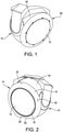
- FIG. 1 illustrates an annular air foil 60 mounted on the spherical cover 30 of the housing 10 in a position that the air foil surrounds a window 12 to control fluid flow over the window.
- the air foil 60 includes an annular body having an inner peripheral edge and an outer peripheral edge.
- the body of the air foil 60 further includes an arcuate outer surface disposed between the inner peripheral edge and the outer peripheral edge.
- the air foil 60 shown in FIG. 1 embodies a complete air foil.
- Airborne electro-optical/infrared turrets have been fitted with air foils in order to improve optical performance. However, these air foils generate excessive aerodynamic torque when the turret is looking aft. Aerodynamic torque limits the operational airspeed. The trend is to place these turrets on faster and faster platforms.
- Embodiments of the present disclosure are directed to a device embodying an air foil that is attached to a window of a turret housing to minimize undesirable density gradients and effectively reduces optical wave front error.
- the air foil surrounds the entire window and the radial size of the air foil may be varied around the circumference to reduce aero-torques to the turret housing at some reduction of flow attachment effectiveness.
- airborne electro-optical/infrared turrets can be fitted with air foils in order to improve optical performance.
- these air foils generate excessive aerodynamic torque when the turret is looking aft. Aerodynamic torque limits the operational airspeed. The trend is to place these turrets on faster and faster platforms.
- Examples not part of the claimed invention of the air foil of the present disclosure include a truncated reduced width portion design to improve aerodynamic torque when the turret is looking aft.
- Embodiments of the invention include an air foil having a movable portion and a truncated air foil that can rotate about the window as required to improve optical performance for a wide range of viewing angles, and to minimize aerodynamic torque when looking aft.
- references to "or” may be construed as inclusive so that any terms described using “or” may indicate any of a single, more than one, and all of the described terms. Any references to front and back, left and right, top and bottom, upper and lower, and vertical and horizontal are intended for convenience of description, not to limit the present systems and methods or their components to any one positional or spatial orientation.
- an optical instrument housing is generally designated at 10.
- the housing 10 which sometimes is referred to as a turret housing, is substantially spherical in construction, and includes a window 12 that is substantially planar.
- the housing 10 is configured to support an optical instrument, including but not limited to visible, infrared, and/or specific spectral bands imaging devices.
- the optical instrument may include an optical transmitter and/or receiver, as well as other devices configured to receive and/or transmit various forms of electromagnetic energy, such as optical, visual, infrared (IR), near IR, thermal IR, microwave, and the like.
- the instrument further may include, but is not limited to, passive sensors, active sensors, imaging sensors, microwave radiometers, synthetic aperture radar (SAR), inverse synthetic aperture radar (ISAR), meteorological radar, forward looking IR, and the like.
- the housing 10 embodies a turret housing, which is mounted on the vehicle, such as an aircraft.
- a device embodying an air foil is mounted on the housing 10 in a position that the air foil 14 surrounds the window 12 to control fluid flow over the window 12.
- the air foil 14 includes an annular body 16 having an inner peripheral edge 18 (not shown) configured to correspond to a peripheral edge of the window 12 of the housing 10, and an outer peripheral edge 20.
- the body 16 of the air foil 14 further includes an arcuate outer, top surface 22 disposed between the inner peripheral edge 18 and the outer peripheral edge 20.
- the arcuate outer surface 22 and the outer peripheral edge 20 together form a substantially smooth surface.
- the inner peripheral edge 18 is rounded, and in a particular embodiment, generally circular in shape.
- the inner peripheral edge 18 is configured to be substantially flush and contiguous with an outer portion of the body 16 forming the window 12 when the air foil 14 is coupled to the body of the housing 10.
- the outer peripheral edge 20 is generally circular in shape.
- the air foil 14 further includes an inner, bottom surface 24, with the bottom surface and the arcuate outer surface 22 defining a thickness therein.
- the air foil 14 further includes a reduced width portion 26 between the inner peripheral edge 18 and the outer peripheral edge 20.
- the reduced width portion 26 is configured to lower elevation torque especially when the housing 10 is looking aft.
- the reduced width portion 26 includes a chord edge 28 that defines an edge portion of the outer peripheral edge 20.
- the air foil 14 having the reduced width portion 26 provides approximately 75% of the optical improvement of a full foil while reducing peak aerodynamic torque by nearly 87% than a full sized foil.
- an air foil having a reduced width portion reduces aerodynamic torque from 93.01 Nm (68.6 foot-pounds (ft-Ibs)) for an air foil having a consistent width to 12.47 Nm (9.2 ft-lbs) when looking aft and exposed to an airflow of 102.89 ms -1 -indicated air speed (200 knots-indicated air speed (KIAS)).
- This capability will allow for greater operational airspeeds of the vehicle on which the housing 10 and optical instrument are mounted.
- the housing 10 includes a spherical cover 30 (also shown in FIGS. 2 and 3 ) and several cast mounting features, each indicated at 32, formed on spherical cover.
- Each mounting feature 32 includes a tapped opening formed therein, the purpose of which will be apparent from the description provided below.
- the air foil 14 is secured to the spherical cover 30 of the housing 10 by several fasteners, each indicated at 34, which are threadably received in the threaded openings of the mounting features 32.
- the fasteners extend through openings, each indicated at 36, formed in the body 16 of the air foil 14. Load spreading washers can be provided to disperse the load of the fastener against the body 16 of the air foil 14.
- the air foil 14 is fabricated from any number of materials.
- the air foil 14 may be constructed by a 3D printing process, composite lay-up, molded plastic or investment casting.
- the thickness between the outer, top surface 22 and the inner, bottom surface 24 is substantially uniform.
- the thickness between the outer surface 22 and the inner surface 24 is substantially non-uniform.
- the air foil 14 includes a seal provided along the inner peripheral edge perimeter 18 to provide a seal between the body 16 of the air foil 14 and the spherical cover 30 of the housing 10.
- air foil 40 is mounted on the spherical cover 30 of the housing 10 in a position that the air foil 40 surrounds the window 12 to control fluid flow over the window 12.
- the air foil 40 includes an annular body 42 having an inner peripheral edge 44 and an outer peripheral edge 46.
- the body 42 of the air foil 40 further includes an arcuate outer surface 48 disposed between the inner peripheral edge 44 and the outer peripheral edge 46.
- the body 42 of the air foil 40 further includes a movable portion 50 that is separate from the remainder of the body 42 and extends from a position adjacent to the inner peripheral edge 44 to the outer peripheral edge 46.
- the movable portion 50 is movable, e.g., by pivoting, with respect to a remainder of the body 42 of the air foil 40. Specifically, the movable portion 50 is movable from a first position in which the movable portion forms a contiguous surface with the remainder of the body 42 ( FIG. 5 ) and a second position in which the movable portion is moved toward the spherical cover 30 of the housing 10 ( FIG. 6 ) to form a truncated edge of the body of the air foil. In the first position, the movable portion 50 is positioned to enable full optical performance. In the second position, the movable portion 50 is retracted toward the spherical cover 30 of the housing 10 to lower the elevation torque. The movable portion 50 is particularly configured to lower elevation torque especially when the turret housing 10 is looking aft. In one embodiment, the air foil 40 further includes a mechanism configured to move the movable portion 50 between the first position and the second position.
- FIG. 7 another air foil of examples of the present disclosure is generally indicated at 70.
- air foil 70 is mounted on the spherical cover 30 of the housing 10 in a position that the air foil 70 surrounds the window 12 to control fluid flow over the window.
- the air foil 70 includes an annular body 72 having an inner peripheral edge 74 and an outer peripheral edge 76.
- the body 72 of the air foil 70 further includes an arcuate outer surface 78 disposed between the inner peripheral edge 74 and the outer peripheral edge 76.
- the air foil 70 further includes a first reduced width portion 80 at one side of the body 72 of the air foil 70 and a second reduced width portion 82 at an opposite side of the body of the air foil 70. Although shown to be symmetrical, the body 72 of the air foil 70 can be asymmetrical.
- the air foil 70 is mounted on and configured to be rotated with respect to the spherical cover 30 of the housing 10.
- the truncated air foil 70 can be rotated about the window 12 as required to improve optical performance for a wide range of viewing angles, and to minimize aerodynamic torque when looking aft.
- the air foil 70 further includes a mechanism configured to rotate the air foil 70 with respect to the spherical cover 30 of the housing 10.
- the air foil 70 can be configured to rotate clockwise, counterclockwise or both to position the truncated portions (first and second reduced width portions 80, 82) to a desired position with respect to the spherical cover 30 of the housing 10.
- FIG. 8 illustrates the turret housing 10 looking forward at a 0° azimuth with a roll position of the air foil 70 being 0°.
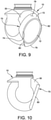
- FIG. 9 illustrates the turret housing 10 looking forward at a 45° azimuth with a roll position of the air foil 70 being 45°.
- FIG. 10 illustrates the turret housing 10 looking forward at a 90° azimuth with a roll position of the air foil 70 being 90°.
- the air foil 70 is configured to rotate as required to provide optical performance of the optical instruments contained within the housing 10.
- the first and/or second reduced width portions 80, 82 may be positioned to reduce aero torque by eliminating a lip of the air foil 70 that produces high torque on the housing 10.
- FIGS. 11 and 12 another air foil of embodiments of the present invention is generally indicated at 110.
- air foil 110 is mounted on the spherical cover 30 of the housing 10 in a position that the air foil 110 surrounds the window 12 to control fluid flow over the window 12.
- the air foil 110 includes an annular body 112 having an inner peripheral edge 114 and an outer peripheral edge 116.
- the body 112 of the air foil 110 further includes an arcuate outer surface 118 disposed between the inner peripheral edge 114 and the outer peripheral edge 116.
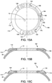
- the air foil 110 further includes a first plurality of slots together indicated at 120 formed in the body 112 along a first portion of a circumference of the body 112.
- the air foil 110 further includes a second plurality of slots together indicated at 122 formed in the body 112 along a second portion of the circumference of the body 112.
- the second plurality of slots 122 is positioned on the body 112 of the air foil 110 at an opposite side of the body of the air foil 110 from the first plurality of slots 120.
- the body 112 of the air foil is secured to the spherical cover 30 of the housing 10 by fasteners in a similar manner as the body 16 of the air foil 14.
- the air foil 110 may include an insert 124 that is coupled to and rotatable with respect to the body 112.
- the insert 124 has a first plurality of slots 126 and a second plurality of slots 128, which when aligned with the first plurality of slots 120 and the second plurality of slots 122 of the body 112 create openings through which air flows.
- the insert 124 is configured to rotate so that the first and second pluralities of slots 120, 122 of the body 112 are covered, thereby preventing air from flowing through the air foil 110.
- the air foil 110 illustrates the first and second pluralities of slots 126, 128 of the insert 124 in an aligned relationship with the first and second pluralities of slots 120, 122 of the body 112 of the air foil 110 to create the openings thereby allowing air to flow through the body 112 of the air foil 110.
- the insert 124 of the air foil 110 can be rotated so that the first and second pluralities of slots 126, 128 are in an offset relationship with the first and second pluralities of slots 120, 122 of the body 112 of the air foil to create a closed, contiguous surface thereby closing the openings and preventing air from flowing through the air foil 110.
- the air foil 110 further includes a mechanism configured to rotate the insert 124 with respect to the body 112 of the air foil 110.
- FIG. 13 illustrates a movement mechanism, generally indicated at 130, configured to move the movable portion 50 with respect to the remainder of the body 42 of the air foil 40, which is described above with reference to FIGS. 5 and 6 .
- the movable portion 50 is pivotally connected to the spherical cover 30 of the air foil 40 by a pivot hinge 132.
- the movement mechanism 130 includes a motor assembly 134 having an integral motor, gearhead, and encoder assembly, which together are configured to drive the rotary motion of a crank 136.
- the crank 136 is connected to a drive link 138 that is pivotally coupled to a follower link 140 provided on the movable member 50.
- the arrangement is such that the movement mechanism 130 is capable of moving the movable member 50 between the first (deployed) position illustrated by solid lines in FIG. 13 and the second (stowed) position illustrated by broken lines in FIG. 13 .
- the movable portion 50 in the deployed position, is positioned to enable full optical performance, and in the stowed position, the movable portion is retracted toward the spherical cover 30 of the housing 10 to lower the elevation torque.
- Connecting the actuator (movement mechanism 130) to the body 42 of the airfoil 40 is one possible approach for implementing the actuator. Another approach is to have the actuator be part of the cover 30 and the linkage connection may be made during the attachment of the airfoil 40.
- a rotary movement mechanism is provided to rotate the air foil 70 with respect to the spherical cover 30 of the housing 10.
- the truncated air foil 70 can be rotated about the window 12 as required to improve optical performance for a wide range of viewing angles, and to minimize aerodynamic torque when looking aft.
- the rotary movement mechanism 150 is configured to rotate the air foil 70 with respect to the spherical cover 30 of the housing 10 in a clockwise direction and/or a counterclockwise direction to a desired position.
- the movement mechanism 150 includes a motor assembly 152 having an integral motor, gearhead, and encoder assembly, which together are configured to drive the rotary motion of a beveled gear 154.
- the beveled gear 154 is configured to drive a mating beveled gear 156 mounted on the body 72 of the air foil 70.
- the movement mechanism 150 further includes an x-contact ball bearing 158 to enable the relative rotary motion of the body 72 of the air foil 70 with respect to the spherical cover 30 of the housing 10.
- the air foil 70 is configured to rotate as required to provide optical performance of the optical instruments contained within the housing 10.
- another rotary movement mechanism is provided to rotate the insert 124 of the air foil 110 with respect to the body 112 of the air foil 110 (each shown in FIGS. 11 and 12 ). As shown in FIGS. 11 and 12 , the slotted air foil 110 can be rotated about the window 12 as required to improve optical performance of the optical instrument.
- the rotary movement mechanism 160 is configured to rotate the insert 124 of the air foil 110 with respect to the body 112 of the air foil 110 in a clockwise direction and/or a counterclockwise direction to open and close the openings created by the alignment of slots 126, 128 of the insert 124 with slots 120, 122 of the body 112.
- the movement mechanism 160 includes a rotary actuator 162, which is configured to drive the rotary motion of a lead screw 164.
- the lead screw 164 is positioned within a threaded nut 166, which is configured to drive the rotation of the insert 124 with respect to the body 112 of the air foil 110 along an upper linkage 168 and a lower linkage 170.
- Linear movement of the threaded nut 166 creates rotation of the insert 124 by the nature of a limited angular rotation. Minor angular misalignment is decoupled by pins provided at the ends of linkages 168 and 170.
- the insert 120 rotates by following shaped tracks with in the air foil 110.
- the air foil increases the high resolution imaging field of regard from azimuth +/-45 degrees and elevation +20 up to -80 down to +/-110 degrees azimuth with the same elevation.
- An optional addition to the air foil includes a moving section to reduce elevation aero load torque for certain look angles.
Landscapes
- Engineering & Computer Science (AREA)
- Aviation & Aerospace Engineering (AREA)
- Mechanical Engineering (AREA)
- Physics & Mathematics (AREA)
- Fluid Mechanics (AREA)
- General Engineering & Computer Science (AREA)
- Aerodynamic Tests, Hydrodynamic Tests, Wind Tunnels, And Water Tanks (AREA)
- Camera Bodies And Camera Details Or Accessories (AREA)
- Accessories Of Cameras (AREA)
Claims (10)
- Dispositif (40) destiné à contrôler l'écoulement d'un fluide sur une fenêtre (12) d'un boîtier d'instrument optique mobile (10), le dispositif comprenant :un corps généralement annulaire (42) configuré pour être fixé autour de la fenêtre du boîtier d'instrument optique mobile, le corps annulaire ayant un bord périphérique intérieur (44) configuré pour correspondre à un bord périphérique de la fenêtre du boîtier et un bord périphérique extérieur (46), et une surface extérieure arquée (48) disposée entre le bord périphérique intérieur et le bord périphérique extérieur,caractérisé en ce que le corps annulaire (42) a une partie mobile (50) positionnée au voisinage du bord périphérique extérieur, la partie mobile étant configurée pour se déplacer par rapport à un reste du corps.
- Dispositif de la revendication 1, dans lequel la partie mobile (50) est mobile par pivotement entre une première position dans laquelle la partie mobile forme une surface contiguë avec le reste du corps (42) et une deuxième position dans laquelle la partie mobile est rétractée vers le boîtier (10).
- Dispositif de la revendication 2, comprenant en outre un mécanisme (130) configuré pour déplacer la partie mobile (50) entre la première position et la deuxième position.
- Dispositif de la revendication 3, dans lequel le mécanisme comporte un ensemble moteur (134) configuré pour faire tourner une manivelle (136) couplée à la partie mobile (50) pour entraîner le mouvement de pivotement de la partie mobile.
- Dispositif (110) destiné à contrôler l'écoulement d'un fluide sur une fenêtre (12) d'un boîtier d'instrument optique mobile (10), le dispositif comprenant :un corps généralement annulaire (112) configuré pour être fixé autour de la fenêtre du boîtier d'instrument optique mobile, le corps annulaire ayant un bord périphérique intérieur (114) configuré pour correspondre à un bord périphérique de la fenêtre du boîtier et un bord périphérique extérieur (116), et une surface extérieure arquée (118) disposée entre le bord périphérique intérieur et le bord périphérique extérieur,caractérisé en ce que le corps annulaire (112) a une pluralité de fentes (120, 122) formées le long d'une partie d'une circonférence du corps.
- Dispositif de la revendication 5, dans lequel la pluralité de fentes constitue une première pluralité de fentes (120) sur un côté du corps du dispositif, et dans lequel le corps comporte une deuxième pluralité de fentes (122) sur un côté opposé du corps du dispositif.
- Procédé destiné à contrôler l'écoulement d'un fluide sur une fenêtre d'un boîtier d'instrument optique sur un véhicule, le procédé comprenant :la fixation d'un dispositif autour de la fenêtre du boîtier, le dispositif comportant un corps généralement annulaire ayant un bord périphérique intérieur configuré pour correspondre à un bord périphérique de la fenêtre du boîtier et un bord périphérique extérieur, une surface extérieure arquée disposée entre le bord périphérique intérieur et le bord périphérique extérieur, et une partie mobile positionnée au voisinage du bord périphérique extérieur, la partie mobile étant configurée pour se déplacer par rapport à un reste du corps ; etle déplacement par pivotement de la partie mobile entre une première position dans laquelle la partie mobile forme une surface contiguë avec le reste du corps et une deuxième position dans laquelle la partie mobile est rétractée vers le boîtier pour réduire le couple aérodynamique.
- Procédé destiné à contrôler l'écoulement d'un fluide sur une fenêtre d'un boîtier d'instrument optique sur un véhicule, le procédé comprenant :
la fixation d'un dispositif autour de la fenêtre du boîtier, le dispositif comportant un corps généralement annulaire ayant un bord périphérique intérieur configuré pour correspondre à un bord périphérique de la fenêtre du boîtier et un bord périphérique extérieur, une surface extérieure arquée disposée entre le bord périphérique intérieur et le bord périphérique extérieur, et une pluralité de fentes formées le long d'une partie d'une circonférence du corps. - Procédé de la revendication 8, dans lequel la pluralité de fentes constitue une première pluralité de fentes sur un côté du corps du dispositif, et dans lequel le corps comporte une deuxième pluralité de fentes sur un côté opposé du corps du dispositif.
- Procédé de la revendication 9, comprenant en outre la rotation d'un mécanisme configuré pour faire tourner une pièce rapportée du dispositif par rapport au boîtier pour ouvrir la première pluralité de fentes et la deuxième pluralité de fentes.
Applications Claiming Priority (2)
| Application Number | Priority Date | Filing Date | Title |
|---|---|---|---|
| US15/381,166 US10174772B2 (en) | 2016-12-16 | 2016-12-16 | Device and method for controlling fluid flow over an optical instrument |
| PCT/US2017/042717 WO2018111346A1 (fr) | 2016-12-16 | 2017-07-19 | Dispositif et procédé de régulation d'écoulement de fluide sur un instrument optique |
Publications (2)
| Publication Number | Publication Date |
|---|---|
| EP3554942A1 EP3554942A1 (fr) | 2019-10-23 |
| EP3554942B1 true EP3554942B1 (fr) | 2022-02-16 |
Family
ID=59684015
Family Applications (1)
| Application Number | Title | Priority Date | Filing Date |
|---|---|---|---|
| EP17755305.4A Active EP3554942B1 (fr) | 2016-12-16 | 2017-07-19 | Dispositif et procédé de régulation d'écoulement de fluide sur un instrument optique |
Country Status (5)
| Country | Link |
|---|---|
| US (1) | US10174772B2 (fr) |
| EP (1) | EP3554942B1 (fr) |
| JP (1) | JP6736775B2 (fr) |
| IL (1) | IL266376B (fr) |
| WO (1) | WO2018111346A1 (fr) |
Family Cites Families (17)
| Publication number | Priority date | Publication date | Assignee | Title |
|---|---|---|---|---|
| US4155521A (en) * | 1975-12-08 | 1979-05-22 | The Singer Company | Cannon launched platform |
| US4677288A (en) * | 1985-02-11 | 1987-06-30 | Northrop Corporation | Optical turret |
| US5069397A (en) * | 1985-09-30 | 1991-12-03 | The Boeing Company | Stabilized aero-optical free shear layer interface |
| US5806789A (en) | 1995-08-22 | 1998-09-15 | Lockheed Corporation | Optical apparatus for an aircraft |
| US5775643A (en) * | 1996-10-18 | 1998-07-07 | The Boeing Company | Passive flow control aero-optical turret assembly |
| FR2875785B1 (fr) | 2004-09-30 | 2007-01-05 | Reims Aviat Ind Soc Par Action | Avion de type reims cessna f406 |
| JP4270267B2 (ja) * | 2006-11-29 | 2009-05-27 | ソニー株式会社 | 鏡筒回転型撮像装置 |
| US7815150B2 (en) * | 2007-08-20 | 2010-10-19 | The Boeing Company | Beam director flow control |
| US8376280B1 (en) * | 2008-01-07 | 2013-02-19 | Bae Systems Information And Electronic Systems Integration Inc. | Aerodynamic deflector shield for protection of optical devices mounted on fixed-wing aircraft |
| US9126697B2 (en) * | 2008-09-29 | 2015-09-08 | The Boeing Company | Atmospheric turbulence isolation system and method |
| EP2338788A1 (fr) | 2009-12-23 | 2011-06-29 | BAE Systems PLC | Équipement d'émission ou de réception monté sur un véhicule aérien |
| US8870122B2 (en) * | 2010-07-23 | 2014-10-28 | The Boeing Company | Method and apparatus for controlling flow about a turret |
| US8635938B2 (en) * | 2011-05-25 | 2014-01-28 | Raytheon Company | Retractable rotary turret |
| US8654314B2 (en) * | 2011-05-25 | 2014-02-18 | Raytheon Company | Rapidly deployable high power laser beam delivery system |
| US9567056B2 (en) | 2014-03-06 | 2017-02-14 | General Atomics Aeronautical Systems, Inc. | Devices, systems and methods for passive control of flow |
| US9592920B2 (en) * | 2014-04-25 | 2017-03-14 | The Boeing Company | Boundary layer flow sensor |
| US20160009360A1 (en) | 2014-07-14 | 2016-01-14 | Raytheon Company | Optical window system with aero-optical conductive blades |
-
2016
- 2016-12-16 US US15/381,166 patent/US10174772B2/en active Active
-
2017
- 2017-07-19 JP JP2019532124A patent/JP6736775B2/ja not_active Expired - Fee Related
- 2017-07-19 EP EP17755305.4A patent/EP3554942B1/fr active Active
- 2017-07-19 WO PCT/US2017/042717 patent/WO2018111346A1/fr not_active Ceased
-
2019
- 2019-05-01 IL IL266376A patent/IL266376B/en active IP Right Grant
Non-Patent Citations (1)
| Title |
|---|
| None * |
Also Published As
| Publication number | Publication date |
|---|---|
| US20180172040A1 (en) | 2018-06-21 |
| IL266376A (en) | 2019-06-30 |
| JP6736775B2 (ja) | 2020-08-05 |
| WO2018111346A1 (fr) | 2018-06-21 |
| EP3554942A1 (fr) | 2019-10-23 |
| IL266376B (en) | 2020-05-31 |
| JP2020508911A (ja) | 2020-03-26 |
| US10174772B2 (en) | 2019-01-08 |
Similar Documents
| Publication | Publication Date | Title |
|---|---|---|
| US10933924B2 (en) | Air guiding apparatus for a motor vehicle body | |
| EP2132527B1 (fr) | Système rétractable pour capteurs aéronautiques | |
| US5094412A (en) | Flaperon system for tilt rotor wings | |
| DE102010024705B4 (de) | Aktive Klappenentlüftung über Formgedächtnislegierung | |
| CA2700427C (fr) | Systeme d'actionnement pour dispositif hypersustentateur de bord d'attaque | |
| US20230059971A1 (en) | Airflow control system and methods thereof | |
| CA2892711C (fr) | Porte de tube de torsion | |
| RU2405715C2 (ru) | Поверхность управления задней кромкой крыла самолета | |
| US10220961B2 (en) | Aerial image capturing system | |
| GB2446707A (en) | Antenna and electronic module support structure with rotational movement about two axes | |
| EP3554942B1 (fr) | Dispositif et procédé de régulation d'écoulement de fluide sur un instrument optique | |
| US20200062376A1 (en) | Nacelle aerodynamic spoiler | |
| WO2019068839A1 (fr) | Système de commande pour véhicules portés par un fluide | |
| US11892275B2 (en) | Drive mechanism for control surface actuation | |
| US10343764B2 (en) | Aircraft wheel fairing drag device | |
| EP3312093B1 (fr) | Appareil et procédés pour déployer un canal d'écoulement de fluide | |
| NL2036683B1 (en) | Adjustable flow influencing assembly for an aircraft | |
| US11293376B2 (en) | Jet engine nacelle comprising a mobile assembly and a reinforced fixed structure | |
| WO2019095841A1 (fr) | Roue à ailettes d'aéronef et aéronef | |
| CN105109664B (zh) | 一种电机驱动的飞机外挂点密封机构 | |
| US11731754B2 (en) | Actuation and support system for aerodynamic surfaces | |
| EP3409583B1 (fr) | Panneau de couverture pour logement de train d'atterissage d'avion | |
| TR2023004170Y (tr) | Bir kapak hareket mekanizması. | |
| FI120030B (fi) | Kattoluukku ja menetelmä kattoluukun käyttämiseksi | |
| IL299298B2 (en) | Long-range reconnaissance pod |
Legal Events
| Date | Code | Title | Description |
|---|---|---|---|
| STAA | Information on the status of an ep patent application or granted ep patent |
Free format text: STATUS: UNKNOWN |
|
| STAA | Information on the status of an ep patent application or granted ep patent |
Free format text: STATUS: THE INTERNATIONAL PUBLICATION HAS BEEN MADE |
|
| PUAI | Public reference made under article 153(3) epc to a published international application that has entered the european phase |
Free format text: ORIGINAL CODE: 0009012 |
|
| STAA | Information on the status of an ep patent application or granted ep patent |
Free format text: STATUS: REQUEST FOR EXAMINATION WAS MADE |
|
| 17P | Request for examination filed |
Effective date: 20190515 |
|
| AK | Designated contracting states |
Kind code of ref document: A1 Designated state(s): AL AT BE BG CH CY CZ DE DK EE ES FI FR GB GR HR HU IE IS IT LI LT LU LV MC MK MT NL NO PL PT RO RS SE SI SK SM TR |
|
| AX | Request for extension of the european patent |
Extension state: BA ME |
|
| DAV | Request for validation of the european patent (deleted) | ||
| DAX | Request for extension of the european patent (deleted) | ||
| GRAP | Despatch of communication of intention to grant a patent |
Free format text: ORIGINAL CODE: EPIDOSNIGR1 |
|
| STAA | Information on the status of an ep patent application or granted ep patent |
Free format text: STATUS: GRANT OF PATENT IS INTENDED |
|
| INTG | Intention to grant announced |
Effective date: 20201124 |
|
| GRAJ | Information related to disapproval of communication of intention to grant by the applicant or resumption of examination proceedings by the epo deleted |
Free format text: ORIGINAL CODE: EPIDOSDIGR1 |
|
| STAA | Information on the status of an ep patent application or granted ep patent |
Free format text: STATUS: REQUEST FOR EXAMINATION WAS MADE |
|
| INTC | Intention to grant announced (deleted) | ||
| GRAP | Despatch of communication of intention to grant a patent |
Free format text: ORIGINAL CODE: EPIDOSNIGR1 |
|
| STAA | Information on the status of an ep patent application or granted ep patent |
Free format text: STATUS: GRANT OF PATENT IS INTENDED |
|
| INTG | Intention to grant announced |
Effective date: 20210421 |
|
| GRAJ | Information related to disapproval of communication of intention to grant by the applicant or resumption of examination proceedings by the epo deleted |
Free format text: ORIGINAL CODE: EPIDOSDIGR1 |
|
| STAA | Information on the status of an ep patent application or granted ep patent |
Free format text: STATUS: REQUEST FOR EXAMINATION WAS MADE |
|
| INTC | Intention to grant announced (deleted) | ||
| GRAP | Despatch of communication of intention to grant a patent |
Free format text: ORIGINAL CODE: EPIDOSNIGR1 |
|
| STAA | Information on the status of an ep patent application or granted ep patent |
Free format text: STATUS: GRANT OF PATENT IS INTENDED |
|
| INTG | Intention to grant announced |
Effective date: 20210825 |
|
| GRAS | Grant fee paid |
Free format text: ORIGINAL CODE: EPIDOSNIGR3 |
|
| GRAA | (expected) grant |
Free format text: ORIGINAL CODE: 0009210 |
|
| STAA | Information on the status of an ep patent application or granted ep patent |
Free format text: STATUS: THE PATENT HAS BEEN GRANTED |
|
| AK | Designated contracting states |
Kind code of ref document: B1 Designated state(s): AL AT BE BG CH CY CZ DE DK EE ES FI FR GB GR HR HU IE IS IT LI LT LU LV MC MK MT NL NO PL PT RO RS SE SI SK SM TR |
|
| REG | Reference to a national code |
Ref country code: GB Ref legal event code: FG4D |
|
| REG | Reference to a national code |
Ref country code: CH Ref legal event code: EP |
|
| REG | Reference to a national code |
Ref country code: DE Ref legal event code: R096 Ref document number: 602017053442 Country of ref document: DE |
|
| REG | Reference to a national code |
Ref country code: AT Ref legal event code: REF Ref document number: 1468727 Country of ref document: AT Kind code of ref document: T Effective date: 20220315 |
|
| REG | Reference to a national code |
Ref country code: IE Ref legal event code: FG4D |
|
| REG | Reference to a national code |
Ref country code: LT Ref legal event code: MG9D |
|
| REG | Reference to a national code |
Ref country code: NL Ref legal event code: MP Effective date: 20220216 |
|
| REG | Reference to a national code |
Ref country code: AT Ref legal event code: MK05 Ref document number: 1468727 Country of ref document: AT Kind code of ref document: T Effective date: 20220216 |
|
| PG25 | Lapsed in a contracting state [announced via postgrant information from national office to epo] |
Ref country code: SE Free format text: LAPSE BECAUSE OF FAILURE TO SUBMIT A TRANSLATION OF THE DESCRIPTION OR TO PAY THE FEE WITHIN THE PRESCRIBED TIME-LIMIT Effective date: 20220216 Ref country code: RS Free format text: LAPSE BECAUSE OF FAILURE TO SUBMIT A TRANSLATION OF THE DESCRIPTION OR TO PAY THE FEE WITHIN THE PRESCRIBED TIME-LIMIT Effective date: 20220216 Ref country code: PT Free format text: LAPSE BECAUSE OF FAILURE TO SUBMIT A TRANSLATION OF THE DESCRIPTION OR TO PAY THE FEE WITHIN THE PRESCRIBED TIME-LIMIT Effective date: 20220616 Ref country code: NO Free format text: LAPSE BECAUSE OF FAILURE TO SUBMIT A TRANSLATION OF THE DESCRIPTION OR TO PAY THE FEE WITHIN THE PRESCRIBED TIME-LIMIT Effective date: 20220516 Ref country code: NL Free format text: LAPSE BECAUSE OF FAILURE TO SUBMIT A TRANSLATION OF THE DESCRIPTION OR TO PAY THE FEE WITHIN THE PRESCRIBED TIME-LIMIT Effective date: 20220216 Ref country code: LT Free format text: LAPSE BECAUSE OF FAILURE TO SUBMIT A TRANSLATION OF THE DESCRIPTION OR TO PAY THE FEE WITHIN THE PRESCRIBED TIME-LIMIT Effective date: 20220216 Ref country code: HR Free format text: LAPSE BECAUSE OF FAILURE TO SUBMIT A TRANSLATION OF THE DESCRIPTION OR TO PAY THE FEE WITHIN THE PRESCRIBED TIME-LIMIT Effective date: 20220216 Ref country code: ES Free format text: LAPSE BECAUSE OF FAILURE TO SUBMIT A TRANSLATION OF THE DESCRIPTION OR TO PAY THE FEE WITHIN THE PRESCRIBED TIME-LIMIT Effective date: 20220216 Ref country code: BG Free format text: LAPSE BECAUSE OF FAILURE TO SUBMIT A TRANSLATION OF THE DESCRIPTION OR TO PAY THE FEE WITHIN THE PRESCRIBED TIME-LIMIT Effective date: 20220516 |
|
| PG25 | Lapsed in a contracting state [announced via postgrant information from national office to epo] |
Ref country code: PL Free format text: LAPSE BECAUSE OF FAILURE TO SUBMIT A TRANSLATION OF THE DESCRIPTION OR TO PAY THE FEE WITHIN THE PRESCRIBED TIME-LIMIT Effective date: 20220216 Ref country code: LV Free format text: LAPSE BECAUSE OF FAILURE TO SUBMIT A TRANSLATION OF THE DESCRIPTION OR TO PAY THE FEE WITHIN THE PRESCRIBED TIME-LIMIT Effective date: 20220216 Ref country code: GR Free format text: LAPSE BECAUSE OF FAILURE TO SUBMIT A TRANSLATION OF THE DESCRIPTION OR TO PAY THE FEE WITHIN THE PRESCRIBED TIME-LIMIT Effective date: 20220517 Ref country code: FI Free format text: LAPSE BECAUSE OF FAILURE TO SUBMIT A TRANSLATION OF THE DESCRIPTION OR TO PAY THE FEE WITHIN THE PRESCRIBED TIME-LIMIT Effective date: 20220216 Ref country code: AT Free format text: LAPSE BECAUSE OF FAILURE TO SUBMIT A TRANSLATION OF THE DESCRIPTION OR TO PAY THE FEE WITHIN THE PRESCRIBED TIME-LIMIT Effective date: 20220216 |
|
| PG25 | Lapsed in a contracting state [announced via postgrant information from national office to epo] |
Ref country code: IS Free format text: LAPSE BECAUSE OF FAILURE TO SUBMIT A TRANSLATION OF THE DESCRIPTION OR TO PAY THE FEE WITHIN THE PRESCRIBED TIME-LIMIT Effective date: 20220617 |
|
| PG25 | Lapsed in a contracting state [announced via postgrant information from national office to epo] |
Ref country code: SM Free format text: LAPSE BECAUSE OF FAILURE TO SUBMIT A TRANSLATION OF THE DESCRIPTION OR TO PAY THE FEE WITHIN THE PRESCRIBED TIME-LIMIT Effective date: 20220216 Ref country code: SK Free format text: LAPSE BECAUSE OF FAILURE TO SUBMIT A TRANSLATION OF THE DESCRIPTION OR TO PAY THE FEE WITHIN THE PRESCRIBED TIME-LIMIT Effective date: 20220216 Ref country code: RO Free format text: LAPSE BECAUSE OF FAILURE TO SUBMIT A TRANSLATION OF THE DESCRIPTION OR TO PAY THE FEE WITHIN THE PRESCRIBED TIME-LIMIT Effective date: 20220216 Ref country code: EE Free format text: LAPSE BECAUSE OF FAILURE TO SUBMIT A TRANSLATION OF THE DESCRIPTION OR TO PAY THE FEE WITHIN THE PRESCRIBED TIME-LIMIT Effective date: 20220216 Ref country code: DK Free format text: LAPSE BECAUSE OF FAILURE TO SUBMIT A TRANSLATION OF THE DESCRIPTION OR TO PAY THE FEE WITHIN THE PRESCRIBED TIME-LIMIT Effective date: 20220216 Ref country code: CZ Free format text: LAPSE BECAUSE OF FAILURE TO SUBMIT A TRANSLATION OF THE DESCRIPTION OR TO PAY THE FEE WITHIN THE PRESCRIBED TIME-LIMIT Effective date: 20220216 |
|
| REG | Reference to a national code |
Ref country code: DE Ref legal event code: R097 Ref document number: 602017053442 Country of ref document: DE |
|
| PG25 | Lapsed in a contracting state [announced via postgrant information from national office to epo] |
Ref country code: AL Free format text: LAPSE BECAUSE OF FAILURE TO SUBMIT A TRANSLATION OF THE DESCRIPTION OR TO PAY THE FEE WITHIN THE PRESCRIBED TIME-LIMIT Effective date: 20220216 |
|
| PLBE | No opposition filed within time limit |
Free format text: ORIGINAL CODE: 0009261 |
|
| STAA | Information on the status of an ep patent application or granted ep patent |
Free format text: STATUS: NO OPPOSITION FILED WITHIN TIME LIMIT |
|
| 26N | No opposition filed |
Effective date: 20221117 |
|
| PG25 | Lapsed in a contracting state [announced via postgrant information from national office to epo] |
Ref country code: SI Free format text: LAPSE BECAUSE OF FAILURE TO SUBMIT A TRANSLATION OF THE DESCRIPTION OR TO PAY THE FEE WITHIN THE PRESCRIBED TIME-LIMIT Effective date: 20220216 Ref country code: MC Free format text: LAPSE BECAUSE OF FAILURE TO SUBMIT A TRANSLATION OF THE DESCRIPTION OR TO PAY THE FEE WITHIN THE PRESCRIBED TIME-LIMIT Effective date: 20220216 |
|
| REG | Reference to a national code |
Ref country code: CH Ref legal event code: PL |
|
| REG | Reference to a national code |
Ref country code: BE Ref legal event code: MM Effective date: 20220731 |
|
| PG25 | Lapsed in a contracting state [announced via postgrant information from national office to epo] |
Ref country code: LU Free format text: LAPSE BECAUSE OF NON-PAYMENT OF DUE FEES Effective date: 20220719 Ref country code: LI Free format text: LAPSE BECAUSE OF NON-PAYMENT OF DUE FEES Effective date: 20220731 Ref country code: FR Free format text: LAPSE BECAUSE OF NON-PAYMENT OF DUE FEES Effective date: 20220731 Ref country code: CH Free format text: LAPSE BECAUSE OF NON-PAYMENT OF DUE FEES Effective date: 20220731 |
|
| PG25 | Lapsed in a contracting state [announced via postgrant information from national office to epo] |
Ref country code: BE Free format text: LAPSE BECAUSE OF NON-PAYMENT OF DUE FEES Effective date: 20220731 |
|
| P01 | Opt-out of the competence of the unified patent court (upc) registered |
Effective date: 20230530 |
|
| PG25 | Lapsed in a contracting state [announced via postgrant information from national office to epo] |
Ref country code: IT Free format text: LAPSE BECAUSE OF FAILURE TO SUBMIT A TRANSLATION OF THE DESCRIPTION OR TO PAY THE FEE WITHIN THE PRESCRIBED TIME-LIMIT Effective date: 20220216 Ref country code: IE Free format text: LAPSE BECAUSE OF NON-PAYMENT OF DUE FEES Effective date: 20220719 |
|
| PG25 | Lapsed in a contracting state [announced via postgrant information from national office to epo] |
Ref country code: HU Free format text: LAPSE BECAUSE OF FAILURE TO SUBMIT A TRANSLATION OF THE DESCRIPTION OR TO PAY THE FEE WITHIN THE PRESCRIBED TIME-LIMIT; INVALID AB INITIO Effective date: 20170719 |
|
| PG25 | Lapsed in a contracting state [announced via postgrant information from national office to epo] |
Ref country code: MK Free format text: LAPSE BECAUSE OF FAILURE TO SUBMIT A TRANSLATION OF THE DESCRIPTION OR TO PAY THE FEE WITHIN THE PRESCRIBED TIME-LIMIT Effective date: 20220216 Ref country code: CY Free format text: LAPSE BECAUSE OF FAILURE TO SUBMIT A TRANSLATION OF THE DESCRIPTION OR TO PAY THE FEE WITHIN THE PRESCRIBED TIME-LIMIT Effective date: 20220216 |
|
| PG25 | Lapsed in a contracting state [announced via postgrant information from national office to epo] |
Ref country code: MT Free format text: LAPSE BECAUSE OF FAILURE TO SUBMIT A TRANSLATION OF THE DESCRIPTION OR TO PAY THE FEE WITHIN THE PRESCRIBED TIME-LIMIT Effective date: 20220216 |
|
| PGFP | Annual fee paid to national office [announced via postgrant information from national office to epo] |
Ref country code: GB Payment date: 20250619 Year of fee payment: 9 |
|
| PGFP | Annual fee paid to national office [announced via postgrant information from national office to epo] |
Ref country code: DE Payment date: 20250620 Year of fee payment: 9 |
|
| PG25 | Lapsed in a contracting state [announced via postgrant information from national office to epo] |
Ref country code: TR Free format text: LAPSE BECAUSE OF FAILURE TO SUBMIT A TRANSLATION OF THE DESCRIPTION OR TO PAY THE FEE WITHIN THE PRESCRIBED TIME-LIMIT Effective date: 20220216 |