EP3554743B1 - Eine integrierte kern-shell-gussform und filter und herstellungsverfahren - Google Patents
Eine integrierte kern-shell-gussform und filter und herstellungsverfahren Download PDFInfo
- Publication number
- EP3554743B1 EP3554743B1 EP17882251.6A EP17882251A EP3554743B1 EP 3554743 B1 EP3554743 B1 EP 3554743B1 EP 17882251 A EP17882251 A EP 17882251A EP 3554743 B1 EP3554743 B1 EP 3554743B1
- Authority
- EP
- European Patent Office
- Prior art keywords
- ceramic
- core
- casting mold
- shell
- mold
- Prior art date
- Legal status (The legal status is an assumption and is not a legal conclusion. Google has not performed a legal analysis and makes no representation as to the accuracy of the status listed.)
- Active
Links
Images


Classifications
-
- B—PERFORMING OPERATIONS; TRANSPORTING
- B22—CASTING; POWDER METALLURGY
- B22C—FOUNDRY MOULDING
- B22C9/00—Moulds or cores; Moulding processes
- B22C9/22—Moulds for peculiarly-shaped castings
-
- B—PERFORMING OPERATIONS; TRANSPORTING
- B22—CASTING; POWDER METALLURGY
- B22C—FOUNDRY MOULDING
- B22C7/00—Patterns; Manufacture thereof so far as not provided for in other classes
- B22C7/02—Lost patterns
-
- B—PERFORMING OPERATIONS; TRANSPORTING
- B22—CASTING; POWDER METALLURGY
- B22C—FOUNDRY MOULDING
- B22C9/00—Moulds or cores; Moulding processes
- B22C9/02—Sand moulds or like moulds for shaped castings
-
- B—PERFORMING OPERATIONS; TRANSPORTING
- B22—CASTING; POWDER METALLURGY
- B22C—FOUNDRY MOULDING
- B22C9/00—Moulds or cores; Moulding processes
- B22C9/02—Sand moulds or like moulds for shaped castings
- B22C9/04—Use of lost patterns
-
- B—PERFORMING OPERATIONS; TRANSPORTING
- B22—CASTING; POWDER METALLURGY
- B22C—FOUNDRY MOULDING
- B22C9/00—Moulds or cores; Moulding processes
- B22C9/08—Features with respect to supply of molten metal, e.g. ingates, circular gates, skim gates
- B22C9/082—Sprues, pouring cups
-
- B—PERFORMING OPERATIONS; TRANSPORTING
- B22—CASTING; POWDER METALLURGY
- B22C—FOUNDRY MOULDING
- B22C9/00—Moulds or cores; Moulding processes
- B22C9/08—Features with respect to supply of molten metal, e.g. ingates, circular gates, skim gates
- B22C9/086—Filters
-
- B—PERFORMING OPERATIONS; TRANSPORTING
- B22—CASTING; POWDER METALLURGY
- B22C—FOUNDRY MOULDING
- B22C9/00—Moulds or cores; Moulding processes
- B22C9/10—Cores; Manufacture or installation of cores
-
- B—PERFORMING OPERATIONS; TRANSPORTING
- B22—CASTING; POWDER METALLURGY
- B22D—CASTING OF METALS; CASTING OF OTHER SUBSTANCES BY THE SAME PROCESSES OR DEVICES
- B22D29/00—Removing castings from moulds, not restricted to casting processes covered by a single main group; Removing cores; Handling ingots
- B22D29/001—Removing cores
- B22D29/002—Removing cores by leaching, washing or dissolving
-
- B—PERFORMING OPERATIONS; TRANSPORTING
- B28—WORKING CEMENT, CLAY, OR STONE
- B28B—SHAPING CLAY OR OTHER CERAMIC COMPOSITIONS; SHAPING SLAG; SHAPING MIXTURES CONTAINING CEMENTITIOUS MATERIAL, e.g. PLASTER
- B28B1/00—Producing shaped prefabricated articles from the material
- B28B1/001—Rapid manufacturing of 3D objects by additive depositing, agglomerating or laminating of material
-
- B—PERFORMING OPERATIONS; TRANSPORTING
- B28—WORKING CEMENT, CLAY, OR STONE
- B28B—SHAPING CLAY OR OTHER CERAMIC COMPOSITIONS; SHAPING SLAG; SHAPING MIXTURES CONTAINING CEMENTITIOUS MATERIAL, e.g. PLASTER
- B28B7/00—Moulds; Cores; Mandrels
- B28B7/34—Moulds, cores, or mandrels of special material, e.g. destructible materials
- B28B7/342—Moulds, cores, or mandrels of special material, e.g. destructible materials which are at least partially destroyed, e.g. broken, molten, before demoulding; Moulding surfaces or spaces shaped by, or in, the ground, or sand or soil, whether bound or not; Cores consisting at least mainly of sand or soil, whether bound or not
-
- B—PERFORMING OPERATIONS; TRANSPORTING
- B28—WORKING CEMENT, CLAY, OR STONE
- B28B—SHAPING CLAY OR OTHER CERAMIC COMPOSITIONS; SHAPING SLAG; SHAPING MIXTURES CONTAINING CEMENTITIOUS MATERIAL, e.g. PLASTER
- B28B7/00—Moulds; Cores; Mandrels
- B28B7/34—Moulds, cores, or mandrels of special material, e.g. destructible materials
- B28B7/346—Manufacture of moulds
-
- B—PERFORMING OPERATIONS; TRANSPORTING
- B29—WORKING OF PLASTICS; WORKING OF SUBSTANCES IN A PLASTIC STATE IN GENERAL
- B29C—SHAPING OR JOINING OF PLASTICS; SHAPING OF MATERIAL IN A PLASTIC STATE, NOT OTHERWISE PROVIDED FOR; AFTER-TREATMENT OF THE SHAPED PRODUCTS, e.g. REPAIRING
- B29C64/00—Additive manufacturing, i.e. manufacturing of three-dimensional [3D] objects by additive deposition, additive agglomeration or additive layering, e.g. by 3D printing, stereolithography or selective laser sintering
- B29C64/10—Processes of additive manufacturing
- B29C64/106—Processes of additive manufacturing using only liquids or viscous materials, e.g. depositing a continuous bead of viscous material
- B29C64/124—Processes of additive manufacturing using only liquids or viscous materials, e.g. depositing a continuous bead of viscous material using layers of liquid which are selectively solidified
- B29C64/129—Processes of additive manufacturing using only liquids or viscous materials, e.g. depositing a continuous bead of viscous material using layers of liquid which are selectively solidified characterised by the energy source therefor, e.g. by global irradiation combined with a mask
- B29C64/135—Processes of additive manufacturing using only liquids or viscous materials, e.g. depositing a continuous bead of viscous material using layers of liquid which are selectively solidified characterised by the energy source therefor, e.g. by global irradiation combined with a mask the energy source being concentrated, e.g. scanning lasers or focused light sources
-
- B—PERFORMING OPERATIONS; TRANSPORTING
- B33—ADDITIVE MANUFACTURING TECHNOLOGY
- B33Y—ADDITIVE MANUFACTURING, i.e. MANUFACTURING OF THREE-DIMENSIONAL [3D] OBJECTS BY ADDITIVE DEPOSITION, ADDITIVE AGGLOMERATION OR ADDITIVE LAYERING, e.g. BY 3D PRINTING, STEREOLITHOGRAPHY OR SELECTIVE LASER SINTERING
- B33Y10/00—Processes of additive manufacturing
-
- B—PERFORMING OPERATIONS; TRANSPORTING
- B33—ADDITIVE MANUFACTURING TECHNOLOGY
- B33Y—ADDITIVE MANUFACTURING, i.e. MANUFACTURING OF THREE-DIMENSIONAL [3D] OBJECTS BY ADDITIVE DEPOSITION, ADDITIVE AGGLOMERATION OR ADDITIVE LAYERING, e.g. BY 3D PRINTING, STEREOLITHOGRAPHY OR SELECTIVE LASER SINTERING
- B33Y80/00—Products made by additive manufacturing
-
- B—PERFORMING OPERATIONS; TRANSPORTING
- B29—WORKING OF PLASTICS; WORKING OF SUBSTANCES IN A PLASTIC STATE IN GENERAL
- B29L—INDEXING SCHEME ASSOCIATED WITH SUBCLASS B29C, RELATING TO PARTICULAR ARTICLES
- B29L2031/00—Other particular articles
- B29L2031/757—Moulds, cores, dies
-
- Y—GENERAL TAGGING OF NEW TECHNOLOGICAL DEVELOPMENTS; GENERAL TAGGING OF CROSS-SECTIONAL TECHNOLOGIES SPANNING OVER SEVERAL SECTIONS OF THE IPC; TECHNICAL SUBJECTS COVERED BY FORMER USPC CROSS-REFERENCE ART COLLECTIONS [XRACs] AND DIGESTS
- Y02—TECHNOLOGIES OR APPLICATIONS FOR MITIGATION OR ADAPTATION AGAINST CLIMATE CHANGE
- Y02P—CLIMATE CHANGE MITIGATION TECHNOLOGIES IN THE PRODUCTION OR PROCESSING OF GOODS
- Y02P10/00—Technologies related to metal processing
- Y02P10/25—Process efficiency
Definitions
- the present disclosure generally relates to investment casting integrated core-shell molds and processes utilizing these integrated molds.
- the core-shell molds made in accordance with the present invention includes integrated ceramic filters for filtering molten metal upon addition to the mold.
- These core-shell molds also include integrated ceramic filaments between the core and shell of the mold that can be utilized to form holes, i.e., effusion cooling holes, in the cast component made from these molds.
- the integrated core-shell molds provide useful properties in casting operations, such as in the casting of superalloys used to make turbine blades and stator vanes for jet aircraft engines or power generation turbine components.
- a turbine blade typically includes hollow airfoils that have radial channels extending along the span of a blade having at least one or more inlets for receiving pressurized cooling air during operation in the engine.
- the various cooling passages in a blade typically include a serpentine channel disposed in the middle of the airfoil between the leading and trailing edges.
- the airfoil typically includes inlets extending through the blade for receiving pressurized cooling air, which include local features such as short turbulator ribs or pins for increasing the heat transfer between the heated sidewalls of the airfoil and the internal cooling air.
- FIG. 1 The manufacture of these turbine blades, typically from high strength, superalloy metal materials, involves numerous steps shown in FIG. 1 .
- a precision ceramic core is manufactured to conform to the intricate cooling passages desired inside the turbine blade.
- a precision die or mold is also created which defines the precise 3-D external surface of the turbine blade including its airfoil, platform, and integral dovetail.
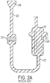
- FIGS. 2A-2C A schematic view of such a mold structure is shown in FIGS. 2A-2C .
- the ceramic core 200 is assembled inside two die halves which form a space or void therebetween that defines the resulting metal portions of the turbine blade. Wax is injected into the assembled dies to fill the void and surround the ceramic core encapsulated therein. The two die halves are split apart and removed from the molded wax.
- the molded wax has the precise configuration of the desired turbine blade.
- the molded wax blade 201 with encapsulated ceramic core 200 is then attached to a wax tree structure 202 that will ultimately define a flowpath for molten metal into the ceramic mold.
- the wax blade includes pins 205 for holding the core in place.
- the tree structure 202 may include a funnel shaped portion 204 for adding molten metal to the mold.
- the tree structure 202 includes a ceramic filter 203 for filtration of molten metal in the casting operation.
- the ceramic filters known in the art include ceramic foam filters (CFF) as shown in FIG. 2D . These filters are formed by impregnating reticulated polyurethane foam with ceramic slip, removing the excess slip by squeezing the foam, and then drying and firing the body forming a CFF.
- CFF ceramic foam filters
- Other known ceramic filters include symmetric filters such as the standard flat primary filter shown in FIG. 2E .
- ceramic filters have been made using various additive technologies. For example, U.S. Patent Application Pub. No. 2016/0038866 A1 entitled “ceramic filters” describes an additively manufactured ceramic filter. Another example is "Advanced Filtration to Improve Single Crystal Casting Yield-Mikro Systems," available at the National Energy Technology Laboratory (NETL) website. These filters are sold as stand-alone filters that may be incorporated in the wax tree as shown in FIG. 2A , and then incorporated into the ceramic mold as shown in FIG. 2B .
- the entire wax tree structure 202, ceramic filter 203, and wax turbine blade 201 is then coated with a ceramic material to form a ceramic shell 206 as shown in FIG. 2B .
- the wax is melted and removed from the shell 206 leaving a corresponding void or space 207 between the ceramic shell 206 and the internal ceramic core 200.
- the ceramic core is held in place after the wax is removed by pins 205.
- molten superalloy metal 208 is then poured into the shell to fill the void 207 therein and again encapsulate the ceramic core 202 contained in the shell 206.
- the molten metal is cooled and solidifies, and then the external shell 206 and internal core 202 are suitably removed leaving behind the desired metallic turbine blade.
- the cast turbine blade may then undergo additional post-casting modifications, such as but not limited to drilling of suitable rows of film cooling holes through the sidewalls of the airfoil as desired for providing outlets for the internally channeled cooling air which then forms a protective cooling air film or blanket over the external surface of the airfoil during operation in the gas turbine engine.
- post-casting modifications are limited and given the ever increasing complexity of turbine engines and the recognized efficiencies of certain cooling circuits inside turbine blades, more complicated and intricate internal geometries are required.
- investment casting is capable of manufacturing these parts, positional precision and intricate internal geometries become more complex to manufacture using these conventional manufacturing processes. Accordingly, it is desired to provide an improved casting method for three dimensional components having intricate internal voids.
- Cooling passages are proposed in the ' 151 patent that include staggered vertical cavities joined by short cylinders, the length of which is nearly the same as its diameter.
- a superalloy turbine blade is then formed in the integrated core-shell mold using known techniques disclosed in the ' 151 patent. After a turbine blade is cast in one of these core-shell molds, the mold is removed to reveal a cast superalloy turbine blade.
- US 2010/003619 A1 and US 2016/221262 A1 each disclose systems and methods for fabricating three-dimensional objects.
- the system includes an optical imaging system providing a light source.
- US 2004/231822 A1 , US 8 851 151 B2 and EP 1152848 A1 each disclose a system for producing cast components from molten metal.
- US 2015/321249 A1 discloses a method for casting an article such as a blade having an attachment root and an airfoil, the airfoil having a proximal end and a distal end.
- the present invention is defined by the appended Claims.
- the invention relates to a method for fabricating a ceramic casting mold in accordance with claim 1.
- the invention also relates to a method of preparing a cast component in accordance with claim 3.
- the cast component is a turbine blade or a stator vane.
- the turbine blade or stator vane is used in a gas turbine engine in, for example, an aircraft engine or power generation.
- the turbine blade is preferably a single crystal cast turbine blade having a cooling hole pattern defined by the ceramic filaments mentioned above.
- the filaments join the core portion and shell portion where each filament spans between the core and shell, the filaments having a cross sectional area ranging from 0.01 to 2 mm 2 .
- the invention in another aspect, relates to a ceramic casting mold in accordance with claim 5.
- the cast component is a turbine blade or stator vane and the plurality of filaments joining the core portion and shell portion define a plurality of cooling holes in the turbine blade upon removal of the mold.
- the plurality of filaments joining the core portion and shell portion have a cross sectional area ranging from 0.01 to 2 mm 2 .
- the ceramic may be a photopolymerized ceramic or a cured photopolymerized ceramic.
- the present invention provides a preferred method for making cast metal parts, and preferably those cast metal parts used in the manufacture of jet aircraft engines. Specifically, the production of single crystal, nickel-based superalloy cast parts such as turbine blades, vanes, and shroud components can be advantageously produced in accordance with this invention. However, other cast metal components may be prepared using the techniques and integrated ceramic molds of the present invention.
- DLP direct light processing
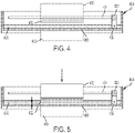
- the apparatus includes a tank 404 having at least one translucent bottom portion 406 covering at least a portion of the exposure unit 410.
- the exposure unit 410 comprises a light source and modulator with which the intensity can be adjusted position-selectively under the control of a control unit, in order to produce an exposure field on the tank bottom 406 with the geometry desired for the layer currently to be formed.
- a laser may be used in the exposure unit, the light beam of which successively scans the exposure field with the desired intensity pattern by means of a mobile mirror, which is controlled by a control unit.
- a production platform 412 is provided above the tank 404; it is supported by a lifting mechanism (not shown) so that it is held in a height-adjustable way over the tank bottom 406 in the region above the exposure unit 410.
- the production platform 412 may likewise be transparent or translucent in order that light can be shone in by a further exposure unit above the production platform in such a way that, at least when forming the first layer on the lower side of the production platform 412, it can also be exposed from above so that the layer cured first on the production platform adheres thereto with even greater reliability.
- the tank 404 contains a filling of highly viscous photopolymerizable material 420.
- the material level of the filling is much higher than the thickness of the layers which are intended to be defined for position-selective exposure.
- the following procedure is adopted.
- the production platform 412 is lowered by the lifting mechanism in a controlled way so that (before the first exposure step) its lower side is immersed in the filling of photopolymerizable material 420 and approaches the tank bottom 406 to such an extent that precisely the desired layer thickness ⁇ (see FIG. 5 ) remains between the lower side of the production platform 412 and the tank bottom 406.
- the desired position-selective layer exposure is carried out for this layer, in order to cure it in the desired shape.
- exposure from above may also take place through the transparent or translucent production platform 412, so that reliable and complete curing takes place particularly in the contact region between the lower side of the production platform 412 and the photopolymerizable material, and therefore good adhesion of the first layer to the production platform 412 is ensured.
- the production platform is raised again by means of the lifting mechanism.
- an elongate mixing element 432 is moved through the filling of photopolymerizable material 420 in the tank.
- the mixing element 432 comprises an elongate wire which is tensioned between two support arms 430 mounted movably on the side walls of the tank 404.
- the support arms 430 may be mounted movably in guide slots 434 in the side walls of the tank 404, so that the wire 432 tensioned between the support arms 430 can be moved relative to the tank 404, parallel to the tank bottom 406, by moving the support arms 430 in the guide slots 434.
- the elongate mixing element 432 has dimensions, and its movement is guided relative to the tank bottom, such that the upper edge of the elongate mixing element 432 remains below the material level of the filling of photopolymerizable material 420 in the tank outside the exposed region. As can be seen in the sectional view of FIG. 8 , the mixing element 432 is below the material level in the tank over the entire length of the wire, and only the support arms 430 protrude beyond the material level in the tank.
- the effect of arranging the elongate mixing element below the material level in the tank 404 is not that the elongate mixing element 432 substantially moves material in front of it during its movement relative to the tank through the exposed region, but rather this material flows over the mixing element 432 while executing a slight upward movement.
- FIG. 7 The movement of the mixing element 432 from the position shown in FIG. 6 , to, for example, a new position in the direction indicated by the arrow A, is shown in FIG. 7 . It has been found that by this type of action on the photopolymerizable material in the tank, the material is effectively stimulated to flow back into the material-depleted exposed region between the production platform 412 and the exposure unit 410.
- the movement of the elongate mixing element 432 relative to the tank may firstly, with a stationary tank 404, be carried out by a linear drive which moves the support arms 430 along the guide slots 434 in order to achieve the desired movement of the elongate mixing element 432 through the exposed region between the production platform 412 and the exposure unit 410.
- the tank bottom 406 has recesses 406' on both sides.
- the support arms 430 project with their lower ends into these recesses 406'. This makes it possible for the elongate mixing element 432 to be held at the height of the tank bottom 406, without interfering with the movement of the lower ends of the support arms 430 through the tank bottom 406.
- the tank may be positioned on a rotatable platform.
- the tank may be rotated relative to the platform and light source to provide a fresh layer of viscous polymer in which to dip the build platform for building the successive layers.
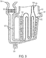
- FIG. 9 shows a schematic side view of an integrated core-shell mold with filaments 902 connecting the core 900 and shell portions 901 of the integrated mold.
- the mold also includes a tube 903 and a funnel section 904 for flowing liquid metal into the integrated mold.
- An integrated filter 905 is provided within the flow-path for liquid metal as shown in FIG. 9 .
- a port 909 is provided for cleaning the integrated core-shell mold before heat treatment and/or metal addition. After printing the ceramic mold by DLP there may be uncured resin within the mold portion or filter portion.
- the port 909 is provided to allow a flowpath for solvent used to remove uncured resin.
- the port 909 is placed underneath the tube 903.
- several cleaning ports may be provided in the tube portion or core-shell mold portion.
- the port 909 may include a screw cap which can be directly printed in the DLP process.
- any method of closing the port may be used.
- the cleaning port is merely a hole in the tube or mold portion that can subsequently be patched with ceramic material prior to curing the mold after the solvent cleaning step is performed.
- filaments are not used to form a cooling hole pattern. Instead, two or more filaments are provided simply to hold the ceramic core 900 in place while metal is poured into the mold.
- the filaments 902 are preferably cylindrical or oval shape, but may be curved or non-linear. Their exact dimensions may be varied according to a desired film cooling scheme for a particular cast metal part.
- cooling holes may have a cross sectional area ranging from 0.01 to 2 mm 2 .
- the cross sectional area may range from 0.01 to 0.15 mm 2 , more preferably from 0.05 to 0.1 mm 2 , and most preferably about 0.07 mm 2 .
- the cooling holes may have a cross sectional area ranging from 0.05 to 0.2 mm 2 , more preferably 0.1 to 0.18 mm 2 , and most preferably about 0.16 mm 2 .
- the spacing of the cooling holes is typically a multiple of the diameter of the cooling holes ranging from 2 ⁇ to 10 ⁇ the diameter of the cooling holes, most preferably about 4-7 ⁇ the diameter of the holes.
- the length of the filament 902 is dictated by the thickness of the cast component, e.g., turbine blade or stator vane wall thickness, and the angle at which the cooling hole is disposed relative to the surface of the cast component.
- the typical lengths range from 0.5 to 5 mm, more preferably between 0.7 to 1 mm, and most preferably about 0.9 mm.
- the angle at which a cooling hole is disposed is approximately 5 to 35° relative to the surface, more preferably between 10 to 20°, and most preferably approximately 12°. It should be appreciated that the methods of casting according to the present invention allow for formation of cooling holes having a lower angle relative to the surface of the cast component than currently available using conventional machining techniques.
- the core shown in FIG. 9 is a hollow core construction.
- One advantage of printing a hollow core is that it reduces the extent of leaching necessary to remove the core after metal casting.
- the core is completely solid ceramic material that can subsequently be leached out.
- both the core and connecting filaments are hollow allowing rapid leaching of the ceramic mold material after casting.
- the ceramic filter is adapted for filtration of molten metal as it is poured into the mold.
- the DLP process described above is particularly suited to provide resolution sufficient to provide porosity for a ceramic filter for filtering molten metal.
- the particular geometry of the filter used with respect to the invention will depend upon the characteristics of the metal to be used and the design requirements of the finished product.
- the geometry of the conventional ceramic filters shown in FIGS. 2D and 2E may be used.
- the filter has a cylindrical shape where the height of the cylinder is less than the diameter of the filter.
- the ceramic filter preferably includes an inlet surface and outlet surface and openings providing a pathway for liquid metal to pass from the inlet surface through the filter and then the outlet surface.
- the openings preferably comprise at least 60% to at least about 90% of a total volume of the ceramic filter. More preferably, the openings comprise at least 70% to at least about 85% of a total volume of the ceramic filter.
- FIG. 10 shows the integrated core-shell mold of FIG. 9 filled with cast metal 1000, such as a nickel based alloy, i.e., Inconel.
- cast metal 1000 such as a nickel based alloy, i.e., Inconel.
- the ceramic is cleaned by rinsing solvent through the port 909. The port is then closed or plugged.
- the metal 1000 is filled into cavity 907, while the hollow core cavity 908 is left unfilled.
- the ceramic core 900, shell 901 and filaments 902 are removed using a combination of chemical and mechanical processes.
- the hollow nature of the core 900 allows for removal of the ceramic mold while minimizing the amount of chemical leaching needed. This saves time and reduces the potential for errors in the manufacturing process.
- a solid core may be used in place of the hollow core if desired.
- hollow filaments may be used in place of solid filaments.
- the resulting cast object is a turbine blade having a cooling hole pattern in the surface of the blade.
- FIGS. 9-10 provide a cross sectional view showing cooling holes at the leading and trailing edge of the turbine blade, that additional cooling holes may be provided where desired including on the sides of the turbine blades or any other location desired.
- the present invention may be used to form cooling holes within the casting process in any particular design. In other words, one would be able to produce conventional cooling holes in any pattern where drilling was used previously to form the cooling holes.
- the present invention will allow for cooling hole patterns previously unattainable due to the limitations of conventional technologies for creating cooling holes within cast components, i.e., drilling.
- the filaments may be used to hold the core in place during casting.
- the holes in the surface provided by the filaments can be closed using a brazing or equivalent operation.
- the filter 905 includes the metal 1000 poured through the funnel and through the filter.
- FIG. 11 shows a cast turbine blade 1100 with cooling holes 1101, 1102 connecting the blade surface to the hollow core 1103 of the blade.
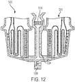
- FIG. 12 shows an example where a filter element 1200 is oriented to filter molten metal before it enters a first cavity of a first turbine blade mold 1201 and a second cavity of a second turbine blade mold 1202. Additional turbine blade molds may be provided in a direction coming out of the page (not shown in the cross-sectional view that is provided).
- a port 1203 is located at the lowest portion of the metal supply tube 1204 for rinsing uncured ceramic polymer from the mold before filling with metal.
- cooling hole filaments may be provided to connect the tip plenum core to the shell in a sufficient quantity to hold the tip plenum core in place during the metal casting step.
- the core-shell mold may be cured and/or fired depending upon the requirements of the ceramic core photopolymer material.
- Molten metal may be poured into the mold to form a cast object in the shape and having the features provided by the integrated core-shell mold.
- the molten metal is preferably a superalloy metal that formed into a single crystal superalloy turbine blade or stator vane using techniques known to be used with conventional investment casting molds.
- the present invention relates to the core-shell mold structures of the present invention incorporated or combined with features of other core-shell molds produced in a similar manner.
Landscapes
- Engineering & Computer Science (AREA)
- Mechanical Engineering (AREA)
- Chemical & Material Sciences (AREA)
- Manufacturing & Machinery (AREA)
- Materials Engineering (AREA)
- Ceramic Engineering (AREA)
- Physics & Mathematics (AREA)
- Optics & Photonics (AREA)
- Molds, Cores, And Manufacturing Methods Thereof (AREA)
- Casting Support Devices, Ladles, And Melt Control Thereby (AREA)
Claims (3)
- Verfahren zur Herstellung einer Keramikgussform, wobei das Verfahren umfasst:(a) In-Kontakt-Bringen eines ausgehärteten Abschnitts eines Werkstücks mit einem Flüssigkeramik-Photopolymer;(b) Bestrahlen eines Abschnitts des Flüssigkeramik-Photopolymers, das an den ausgehärteten Abschnitt angrenzt, durch ein Fenster, welches das Flüssigkeramik-Polymer berührt;(c) Entnehmen des Werkstücks aus dem ungehärteten Flüssigkeramik-Photopolymer; und(d) Wiederholen der Schritte (a) - (c), bis eine Keramikgussform gebildet ist, wobei die Keramikgussform einen Kernabschnitt (900), einen Schalenabschnitt (901) und einen integrierten Keramikfilterabschnitt (905) zum Filtern von Metallschmelze bei Hinzugabe in die Keramikgussform aufweist, mit mindestens einer Kavität zwischen dem Kernabschnitt (900) und dem Schalenabschnitt (901), wobei die Kavität eingerichtet ist, bei Anlage und Entfernung der Keramikgussform die Form eines Gussteils zu definieren, und der Filterabschnitt (905) in Richtung der in die Kavität der Keramikgussform fließenden Metallschmelze angeordnet ist; wobei die Keramikgussform eine Vielzahl von Filamenten (902) aufweist, die den Kernabschnitt (900) und Schalenabschnitt (901) verbinden.
- Verfahren zur Herstellung eines Gussteils, wobei das Verfahren umfasst:Gießen eines flüssigen Metalls (1000) in eine Keramikgussform und Erstarren des flüssigen Metalls zur Bildung des Gussteils, die Keramikgussform wird nach Anspruch 1 angefertigt, und weist einen Kernabschnitt (900), einen Schalenabschnitt (901) und einen integrierten Filterabschnitt (905) zum Filtern von Metallschmelze bei Anlage und Entfernung der Keramikgussform auf, mit mindestens einer Kavität zwischen dem Kernabschnitt (900) und dem Schalenabschnitt (901), wobei die Kavität eingerichtet ist, bei Anlage und Entfernung der Keramikgussform die Form eines Gussteils zu definieren, und der Filterabschnitt (905) in Richtung der in die Kavität der Keramikgussform fließenden Metallschmelze angeordnet ist; wobei dieKeramikgussform eine Vielzahl von Filamenten (902) aufweist, die sich mit dem Kernabschnitt (900) und Schalenabschnitt (901) verbinden; undEntfernen der Keramikgussform von dem Gussteil durch Herauslösen mindestens eines Abschnitts des Keramikkerns durch die Löcher in dem Gussteil, welche durch die Filamente (902) bereitgestellt werden.
- Keramikgussform aus einem Flüssigkeramik-Photopolymer, aufweisend:einen Kernabschnitt (900), einen Schalenabschnitt (901) und einen integrierten Keramikfilterabschnitt (905) zum Filtern von Metallschmelze bei Anlage und Entfernung der Keramikgussform, mit mindestens einer Kavität zwischen dem Kernabschnitt (900) und dem Schalenabschnitt (901), wobei die Kavität eingerichtet ist, die Form eines Gussteils bei Anlage und Entfernung der Keramikgussform zu definieren, und den Filterabschnitt (905), der in Richtung der in die Kavität der Keramikgussform fließenden Metallschmelze angeordnet ist; undeine Vielzahl von Filamenten (902), die den Kernabschnitt (900) und Schalenabschnitt (901) verbinden.
Applications Claiming Priority (2)
| Application Number | Priority Date | Filing Date | Title |
|---|---|---|---|
| US15/377,759 US20180161856A1 (en) | 2016-12-13 | 2016-12-13 | Integrated casting core-shell structure and filter for making cast component |
| PCT/US2017/060165 WO2018111438A1 (en) | 2016-12-13 | 2017-11-06 | Integrated casting core-shell structure and filter for making cast component |
Publications (3)
| Publication Number | Publication Date |
|---|---|
| EP3554743A1 EP3554743A1 (de) | 2019-10-23 |
| EP3554743A4 EP3554743A4 (de) | 2020-07-22 |
| EP3554743B1 true EP3554743B1 (de) | 2022-04-27 |
Family
ID=62488257
Family Applications (1)
| Application Number | Title | Priority Date | Filing Date |
|---|---|---|---|
| EP17882251.6A Active EP3554743B1 (de) | 2016-12-13 | 2017-11-06 | Eine integrierte kern-shell-gussform und filter und herstellungsverfahren |
Country Status (6)
| Country | Link |
|---|---|
| US (1) | US20180161856A1 (de) |
| EP (1) | EP3554743B1 (de) |
| JP (2) | JP6884862B2 (de) |
| CN (1) | CN110072649A (de) |
| CA (1) | CA3045618C (de) |
| WO (1) | WO2018111438A1 (de) |
Families Citing this family (21)
| Publication number | Priority date | Publication date | Assignee | Title |
|---|---|---|---|---|
| US20180161854A1 (en) * | 2016-12-13 | 2018-06-14 | General Electric Company | Integrated casting core-shell structure |
| US20180161852A1 (en) * | 2016-12-13 | 2018-06-14 | General Electric Company | Integrated casting core-shell structure with printed tubes for making cast component |
| US20180161866A1 (en) | 2016-12-13 | 2018-06-14 | General Electric Company | Multi-piece integrated core-shell structure for making cast component |
| US10807154B2 (en) * | 2016-12-13 | 2020-10-20 | General Electric Company | Integrated casting core-shell structure for making cast component with cooling holes in inaccessible locations |
| US11813669B2 (en) | 2016-12-13 | 2023-11-14 | General Electric Company | Method for making an integrated core-shell structure |
| US20180161853A1 (en) * | 2016-12-13 | 2018-06-14 | General Electric Company | Integrated casting core-shell structure with floating tip plenum |
| US10625342B2 (en) | 2017-02-22 | 2020-04-21 | General Electric Company | Method of repairing turbine component |
| US11154956B2 (en) | 2017-02-22 | 2021-10-26 | General Electric Company | Method of repairing turbine component using ultra-thin plate |
| US10702958B2 (en) | 2017-02-22 | 2020-07-07 | General Electric Company | Method of manufacturing turbine airfoil and tip component thereof using ceramic core with witness feature |
| US10610933B2 (en) | 2017-02-22 | 2020-04-07 | General Electric Company | Method of manufacturing turbine airfoil with open tip casting and tip component thereof |
| US10717130B2 (en) | 2017-02-22 | 2020-07-21 | General Electric Company | Method of manufacturing turbine airfoil and tip component thereof |
| US10974312B2 (en) * | 2017-06-28 | 2021-04-13 | General Electric Company | Additively manufactured casting core-shell mold with integrated filter and ceramic shell |
| US10780498B2 (en) | 2018-08-22 | 2020-09-22 | General Electric Company | Porous tools and methods of making the same |
| US12392290B2 (en) | 2022-11-01 | 2025-08-19 | General Electric Company | Gas turbine engine |
| US12535033B2 (en) | 2022-11-01 | 2026-01-27 | General Electric Company | Gas turbine engine |
| US12410753B2 (en) | 2022-11-01 | 2025-09-09 | General Electric Company | Gas turbine engine |
| US12503980B2 (en) | 2022-11-01 | 2025-12-23 | General Electric Company | Gas turbine engine |
| US12196131B2 (en) | 2022-11-01 | 2025-01-14 | General Electric Company | Gas turbine engine |
| US12428992B2 (en) | 2022-11-01 | 2025-09-30 | General Electric Company | Gas turbine engine |
| US12540551B1 (en) | 2025-07-01 | 2026-02-03 | General Electric Company | Gas turbine engines including splittered airfoils |
| CN120619319B (zh) * | 2025-08-14 | 2025-10-24 | 中国机械总院集团沈阳铸造研究所有限公司 | 反重力熔模精铸造型装置及方法 |
Citations (1)
| Publication number | Priority date | Publication date | Assignee | Title |
|---|---|---|---|---|
| US20100028645A1 (en) * | 2008-08-04 | 2010-02-04 | Michael Maguire | Adaptive supports for green state articles and methods of processing thereof |
Family Cites Families (24)
| Publication number | Priority date | Publication date | Assignee | Title |
|---|---|---|---|---|
| US4532974A (en) * | 1981-07-03 | 1985-08-06 | Rolls-Royce Limited | Component casting |
| US5256340A (en) | 1988-04-18 | 1993-10-26 | 3D Systems, Inc. | Method of making a three-dimensional object by stereolithography |
| US5387380A (en) | 1989-12-08 | 1995-02-07 | Massachusetts Institute Of Technology | Three-dimensional printing techniques |
| JPH11285782A (ja) * | 1997-11-18 | 1999-10-19 | Bridgestone Corp | セラミックフィルター及び金属溶湯の濾過方法 |
| CA2351322C (en) * | 1998-11-20 | 2008-07-29 | Rolls-Royce Corporation | Method and apparatus for production of a cast component |
| US6932145B2 (en) | 1998-11-20 | 2005-08-23 | Rolls-Royce Corporation | Method and apparatus for production of a cast component |
| US7343960B1 (en) * | 1998-11-20 | 2008-03-18 | Rolls-Royce Corporation | Method and apparatus for production of a cast component |
| US6186217B1 (en) * | 1998-12-01 | 2001-02-13 | Howmet Research Corporation | Multipiece core assembly |
| US6331267B1 (en) * | 1999-11-16 | 2001-12-18 | General Electric Company | Apparatus and method for molding a core for use in casting hollow parts |
| US7201212B2 (en) * | 2003-08-28 | 2007-04-10 | United Technologies Corporation | Investment casting |
| CN1280040C (zh) * | 2004-06-25 | 2006-10-18 | 哈尔滨工业大学 | 含有过滤器的高尔夫球杆头熔模铸造陶瓷型壳的制备方法 |
| JP2006306633A (ja) | 2005-04-26 | 2006-11-09 | Bridgestone Corp | 溶融金属濾過用セラミックフィルター及び溶融金属濾過方法 |
| PL2024114T3 (pl) | 2006-04-19 | 2019-02-28 | Howmet Corporation | Sekwencyjne napełnianie formy |
| US8636496B2 (en) * | 2008-05-05 | 2014-01-28 | Georgia Tech Research Corporation | Systems and methods for fabricating three-dimensional objects |
| US9561622B2 (en) * | 2008-05-05 | 2017-02-07 | Georgia Tech Research Corporation | Systems and methods for fabricating three-dimensional objects |
| WO2010045950A1 (de) | 2008-10-20 | 2010-04-29 | Ivoclar Vivadent Ag | Vorrichtung und verfahren zur verarbeitung von lichtpolymerisierbarem material zum schichtweisen aufbau von formkörpern |
| US8794298B2 (en) * | 2009-12-30 | 2014-08-05 | Rolls-Royce Corporation | Systems and methods for filtering molten metal |
| US20130333855A1 (en) * | 2010-12-07 | 2013-12-19 | Gary B. Merrill | Investment casting utilizing flexible wax pattern tool for supporting a ceramic core along its length during wax injection |
| EP2505341B1 (de) * | 2011-03-29 | 2013-05-08 | Ivoclar Vivadent AG | Verfahren zum schichtweisen Aufbau eines Formkörpers aus hochviskosem photopolymerisierbarem Material |
| US8393381B2 (en) * | 2011-05-18 | 2013-03-12 | Pcc Airfoils, Inc. | Method of forming a cast metal article |
| EP3513889B1 (de) | 2012-12-14 | 2021-04-14 | Raytheon Technologies Corporation | Legierung und hybridturbinenschaufel für verbesserte motorleistung oder -architektur |
| US9835035B2 (en) | 2013-03-12 | 2017-12-05 | Howmet Corporation | Cast-in cooling features especially for turbine airfoils |
| CN105102099B (zh) | 2013-03-15 | 2018-10-19 | 派罗特克公司 | 陶瓷过滤器 |
| US10307817B2 (en) * | 2014-10-31 | 2019-06-04 | United Technologies Corporation | Additively manufactured casting articles for manufacturing gas turbine engine parts |
-
2016
- 2016-12-13 US US15/377,759 patent/US20180161856A1/en not_active Abandoned
-
2017
- 2017-11-06 WO PCT/US2017/060165 patent/WO2018111438A1/en not_active Ceased
- 2017-11-06 CN CN201780076870.9A patent/CN110072649A/zh active Pending
- 2017-11-06 CA CA3045618A patent/CA3045618C/en active Active
- 2017-11-06 EP EP17882251.6A patent/EP3554743B1/de active Active
- 2017-11-06 JP JP2019531717A patent/JP6884862B2/ja active Active
-
2021
- 2021-05-12 JP JP2021080822A patent/JP7235802B2/ja active Active
Patent Citations (1)
| Publication number | Priority date | Publication date | Assignee | Title |
|---|---|---|---|---|
| US20100028645A1 (en) * | 2008-08-04 | 2010-02-04 | Michael Maguire | Adaptive supports for green state articles and methods of processing thereof |
Also Published As
| Publication number | Publication date |
|---|---|
| EP3554743A1 (de) | 2019-10-23 |
| US20180161856A1 (en) | 2018-06-14 |
| JP2020501908A (ja) | 2020-01-23 |
| WO2018111438A1 (en) | 2018-06-21 |
| JP2021121447A (ja) | 2021-08-26 |
| JP7235802B2 (ja) | 2023-03-08 |
| JP6884862B2 (ja) | 2021-06-09 |
| CA3045618C (en) | 2024-05-14 |
| EP3554743A4 (de) | 2020-07-22 |
| CA3045618A1 (en) | 2018-06-21 |
| CN110072649A (zh) | 2019-07-30 |
Similar Documents
| Publication | Publication Date | Title |
|---|---|---|
| EP3554743B1 (de) | Eine integrierte kern-shell-gussform und filter und herstellungsverfahren | |
| EP3554740B1 (de) | Verfahren zur herstellung einer keramikgussform | |
| CA3045623C (en) | Integrated casting core-shell structure | |
| EP3554748B1 (de) | Integrierte kern-schale-giessstruktur mit schwimmender spitzenkammer | |
| EP3554747B1 (de) | Integrierte kern-schale-giessstruktur zur herstellung eines gussteils mit nichtlinearen öffnungen | |
| CA3045607C (en) | Multi-piece integrated core-shell structure for making cast component | |
| EP3558562B1 (de) | Verfahren zur herstellung einer integrierten kern-schale-gussform zur herstellung eines gussteils mit kühllöchern an unzugänglichen stellen | |
| US20180161855A1 (en) | Multi-piece integrated core-shell structure with standoff and/or bumper for making cast component | |
| CA3045613A1 (en) | Integrated casting core-shell structure for making cast components having thin root components |
Legal Events
| Date | Code | Title | Description |
|---|---|---|---|
| STAA | Information on the status of an ep patent application or granted ep patent |
Free format text: STATUS: THE INTERNATIONAL PUBLICATION HAS BEEN MADE |
|
| PUAI | Public reference made under article 153(3) epc to a published international application that has entered the european phase |
Free format text: ORIGINAL CODE: 0009012 |
|
| STAA | Information on the status of an ep patent application or granted ep patent |
Free format text: STATUS: REQUEST FOR EXAMINATION WAS MADE |
|
| 17P | Request for examination filed |
Effective date: 20190528 |
|
| AK | Designated contracting states |
Kind code of ref document: A1 Designated state(s): AL AT BE BG CH CY CZ DE DK EE ES FI FR GB GR HR HU IE IS IT LI LT LU LV MC MK MT NL NO PL PT RO RS SE SI SK SM TR |
|
| AX | Request for extension of the european patent |
Extension state: BA ME |
|
| RIN1 | Information on inventor provided before grant (corrected) |
Inventor name: GARAY, GREGORY, TERRENCE Inventor name: DEINES, JAMES, HERBERT Inventor name: YANG, XI Inventor name: MCCARREN, MICHAEL, JOHN Inventor name: PETERSON, BRIAN, PATRICK Inventor name: PRZESLAWSKI, BRIAN, DAVID |
|
| DAV | Request for validation of the european patent (deleted) | ||
| DAX | Request for extension of the european patent (deleted) | ||
| A4 | Supplementary search report drawn up and despatched |
Effective date: 20200619 |
|
| RIC1 | Information provided on ipc code assigned before grant |
Ipc: B22C 9/08 20060101ALI20200615BHEP Ipc: B22C 9/24 20060101AFI20200615BHEP Ipc: B22C 7/02 20060101ALI20200615BHEP Ipc: B28B 1/00 20060101ALI20200615BHEP Ipc: B33Y 10/00 20150101ALI20200615BHEP Ipc: B33Y 80/00 20150101ALI20200615BHEP Ipc: B22C 9/04 20060101ALI20200615BHEP Ipc: B28B 7/34 20060101ALI20200615BHEP Ipc: B22C 9/22 20060101ALI20200615BHEP Ipc: B29C 64/135 20170101ALI20200615BHEP Ipc: B22D 29/00 20060101ALI20200615BHEP |
|
| STAA | Information on the status of an ep patent application or granted ep patent |
Free format text: STATUS: EXAMINATION IS IN PROGRESS |
|
| 17Q | First examination report despatched |
Effective date: 20210223 |
|
| REG | Reference to a national code |
Ref country code: DE Ref legal event code: R079 Ref document number: 602017056715 Country of ref document: DE Free format text: PREVIOUS MAIN CLASS: B22C0009240000 Ipc: B22C0009220000 |
|
| RIC1 | Information provided on ipc code assigned before grant |
Ipc: B22C 9/10 20060101ALI20210906BHEP Ipc: B22C 9/08 20060101ALI20210906BHEP Ipc: B22C 9/02 20060101ALI20210906BHEP Ipc: B33Y 80/00 20150101ALI20210906BHEP Ipc: B33Y 10/00 20150101ALI20210906BHEP Ipc: B28B 7/34 20060101ALI20210906BHEP Ipc: B28B 1/00 20060101ALI20210906BHEP Ipc: B22D 29/00 20060101ALI20210906BHEP Ipc: B22C 9/22 20060101AFI20210906BHEP |
|
| GRAP | Despatch of communication of intention to grant a patent |
Free format text: ORIGINAL CODE: EPIDOSNIGR1 |
|
| STAA | Information on the status of an ep patent application or granted ep patent |
Free format text: STATUS: GRANT OF PATENT IS INTENDED |
|
| INTG | Intention to grant announced |
Effective date: 20211105 |
|
| GRAS | Grant fee paid |
Free format text: ORIGINAL CODE: EPIDOSNIGR3 |
|
| GRAA | (expected) grant |
Free format text: ORIGINAL CODE: 0009210 |
|
| STAA | Information on the status of an ep patent application or granted ep patent |
Free format text: STATUS: THE PATENT HAS BEEN GRANTED |
|
| AK | Designated contracting states |
Kind code of ref document: B1 Designated state(s): AL AT BE BG CH CY CZ DE DK EE ES FI FR GB GR HR HU IE IS IT LI LT LU LV MC MK MT NL NO PL PT RO RS SE SI SK SM TR |
|
| REG | Reference to a national code |
Ref country code: GB Ref legal event code: FG4D |
|
| REG | Reference to a national code |
Ref country code: CH Ref legal event code: EP |
|
| REG | Reference to a national code |
Ref country code: AT Ref legal event code: REF Ref document number: 1486541 Country of ref document: AT Kind code of ref document: T Effective date: 20220515 |
|
| REG | Reference to a national code |
Ref country code: DE Ref legal event code: R096 Ref document number: 602017056715 Country of ref document: DE |
|
| REG | Reference to a national code |
Ref country code: IE Ref legal event code: FG4D |
|
| REG | Reference to a national code |
Ref country code: LT Ref legal event code: MG9D |
|
| REG | Reference to a national code |
Ref country code: NL Ref legal event code: MP Effective date: 20220427 |
|
| REG | Reference to a national code |
Ref country code: AT Ref legal event code: MK05 Ref document number: 1486541 Country of ref document: AT Kind code of ref document: T Effective date: 20220427 |
|
| PG25 | Lapsed in a contracting state [announced via postgrant information from national office to epo] |
Ref country code: NL Free format text: LAPSE BECAUSE OF FAILURE TO SUBMIT A TRANSLATION OF THE DESCRIPTION OR TO PAY THE FEE WITHIN THE PRESCRIBED TIME-LIMIT Effective date: 20220427 |
|
| PG25 | Lapsed in a contracting state [announced via postgrant information from national office to epo] |
Ref country code: SE Free format text: LAPSE BECAUSE OF FAILURE TO SUBMIT A TRANSLATION OF THE DESCRIPTION OR TO PAY THE FEE WITHIN THE PRESCRIBED TIME-LIMIT Effective date: 20220427 Ref country code: PT Free format text: LAPSE BECAUSE OF FAILURE TO SUBMIT A TRANSLATION OF THE DESCRIPTION OR TO PAY THE FEE WITHIN THE PRESCRIBED TIME-LIMIT Effective date: 20220829 Ref country code: NO Free format text: LAPSE BECAUSE OF FAILURE TO SUBMIT A TRANSLATION OF THE DESCRIPTION OR TO PAY THE FEE WITHIN THE PRESCRIBED TIME-LIMIT Effective date: 20220727 Ref country code: LT Free format text: LAPSE BECAUSE OF FAILURE TO SUBMIT A TRANSLATION OF THE DESCRIPTION OR TO PAY THE FEE WITHIN THE PRESCRIBED TIME-LIMIT Effective date: 20220427 Ref country code: HR Free format text: LAPSE BECAUSE OF FAILURE TO SUBMIT A TRANSLATION OF THE DESCRIPTION OR TO PAY THE FEE WITHIN THE PRESCRIBED TIME-LIMIT Effective date: 20220427 Ref country code: GR Free format text: LAPSE BECAUSE OF FAILURE TO SUBMIT A TRANSLATION OF THE DESCRIPTION OR TO PAY THE FEE WITHIN THE PRESCRIBED TIME-LIMIT Effective date: 20220728 Ref country code: FI Free format text: LAPSE BECAUSE OF FAILURE TO SUBMIT A TRANSLATION OF THE DESCRIPTION OR TO PAY THE FEE WITHIN THE PRESCRIBED TIME-LIMIT Effective date: 20220427 Ref country code: ES Free format text: LAPSE BECAUSE OF FAILURE TO SUBMIT A TRANSLATION OF THE DESCRIPTION OR TO PAY THE FEE WITHIN THE PRESCRIBED TIME-LIMIT Effective date: 20220427 Ref country code: BG Free format text: LAPSE BECAUSE OF FAILURE TO SUBMIT A TRANSLATION OF THE DESCRIPTION OR TO PAY THE FEE WITHIN THE PRESCRIBED TIME-LIMIT Effective date: 20220727 Ref country code: AT Free format text: LAPSE BECAUSE OF FAILURE TO SUBMIT A TRANSLATION OF THE DESCRIPTION OR TO PAY THE FEE WITHIN THE PRESCRIBED TIME-LIMIT Effective date: 20220427 |
|
| PG25 | Lapsed in a contracting state [announced via postgrant information from national office to epo] |
Ref country code: RS Free format text: LAPSE BECAUSE OF FAILURE TO SUBMIT A TRANSLATION OF THE DESCRIPTION OR TO PAY THE FEE WITHIN THE PRESCRIBED TIME-LIMIT Effective date: 20220427 Ref country code: PL Free format text: LAPSE BECAUSE OF FAILURE TO SUBMIT A TRANSLATION OF THE DESCRIPTION OR TO PAY THE FEE WITHIN THE PRESCRIBED TIME-LIMIT Effective date: 20220427 Ref country code: LV Free format text: LAPSE BECAUSE OF FAILURE TO SUBMIT A TRANSLATION OF THE DESCRIPTION OR TO PAY THE FEE WITHIN THE PRESCRIBED TIME-LIMIT Effective date: 20220427 Ref country code: IS Free format text: LAPSE BECAUSE OF FAILURE TO SUBMIT A TRANSLATION OF THE DESCRIPTION OR TO PAY THE FEE WITHIN THE PRESCRIBED TIME-LIMIT Effective date: 20220827 |
|
| REG | Reference to a national code |
Ref country code: DE Ref legal event code: R097 Ref document number: 602017056715 Country of ref document: DE |
|
| PG25 | Lapsed in a contracting state [announced via postgrant information from national office to epo] |
Ref country code: SM Free format text: LAPSE BECAUSE OF FAILURE TO SUBMIT A TRANSLATION OF THE DESCRIPTION OR TO PAY THE FEE WITHIN THE PRESCRIBED TIME-LIMIT Effective date: 20220427 Ref country code: SK Free format text: LAPSE BECAUSE OF FAILURE TO SUBMIT A TRANSLATION OF THE DESCRIPTION OR TO PAY THE FEE WITHIN THE PRESCRIBED TIME-LIMIT Effective date: 20220427 Ref country code: RO Free format text: LAPSE BECAUSE OF FAILURE TO SUBMIT A TRANSLATION OF THE DESCRIPTION OR TO PAY THE FEE WITHIN THE PRESCRIBED TIME-LIMIT Effective date: 20220427 Ref country code: EE Free format text: LAPSE BECAUSE OF FAILURE TO SUBMIT A TRANSLATION OF THE DESCRIPTION OR TO PAY THE FEE WITHIN THE PRESCRIBED TIME-LIMIT Effective date: 20220427 Ref country code: DK Free format text: LAPSE BECAUSE OF FAILURE TO SUBMIT A TRANSLATION OF THE DESCRIPTION OR TO PAY THE FEE WITHIN THE PRESCRIBED TIME-LIMIT Effective date: 20220427 Ref country code: CZ Free format text: LAPSE BECAUSE OF FAILURE TO SUBMIT A TRANSLATION OF THE DESCRIPTION OR TO PAY THE FEE WITHIN THE PRESCRIBED TIME-LIMIT Effective date: 20220427 |
|
| PLBE | No opposition filed within time limit |
Free format text: ORIGINAL CODE: 0009261 |
|
| STAA | Information on the status of an ep patent application or granted ep patent |
Free format text: STATUS: NO OPPOSITION FILED WITHIN TIME LIMIT |
|
| PG25 | Lapsed in a contracting state [announced via postgrant information from national office to epo] |
Ref country code: AL Free format text: LAPSE BECAUSE OF FAILURE TO SUBMIT A TRANSLATION OF THE DESCRIPTION OR TO PAY THE FEE WITHIN THE PRESCRIBED TIME-LIMIT Effective date: 20220427 |
|
| 26N | No opposition filed |
Effective date: 20230130 |
|
| PG25 | Lapsed in a contracting state [announced via postgrant information from national office to epo] |
Ref country code: SI Free format text: LAPSE BECAUSE OF FAILURE TO SUBMIT A TRANSLATION OF THE DESCRIPTION OR TO PAY THE FEE WITHIN THE PRESCRIBED TIME-LIMIT Effective date: 20220427 |
|
| P01 | Opt-out of the competence of the unified patent court (upc) registered |
Effective date: 20230515 |
|
| PG25 | Lapsed in a contracting state [announced via postgrant information from national office to epo] |
Ref country code: MC Free format text: LAPSE BECAUSE OF FAILURE TO SUBMIT A TRANSLATION OF THE DESCRIPTION OR TO PAY THE FEE WITHIN THE PRESCRIBED TIME-LIMIT Effective date: 20220427 |
|
| REG | Reference to a national code |
Ref country code: CH Ref legal event code: PL |
|
| REG | Reference to a national code |
Ref country code: BE Ref legal event code: MM Effective date: 20221130 |
|
| PG25 | Lapsed in a contracting state [announced via postgrant information from national office to epo] |
Ref country code: LI Free format text: LAPSE BECAUSE OF NON-PAYMENT OF DUE FEES Effective date: 20221130 Ref country code: CH Free format text: LAPSE BECAUSE OF NON-PAYMENT OF DUE FEES Effective date: 20221130 |
|
| PG25 | Lapsed in a contracting state [announced via postgrant information from national office to epo] |
Ref country code: LU Free format text: LAPSE BECAUSE OF NON-PAYMENT OF DUE FEES Effective date: 20221106 |
|
| PG25 | Lapsed in a contracting state [announced via postgrant information from national office to epo] |
Ref country code: IE Free format text: LAPSE BECAUSE OF NON-PAYMENT OF DUE FEES Effective date: 20221106 |
|
| PG25 | Lapsed in a contracting state [announced via postgrant information from national office to epo] |
Ref country code: BE Free format text: LAPSE BECAUSE OF NON-PAYMENT OF DUE FEES Effective date: 20221130 |
|
| PG25 | Lapsed in a contracting state [announced via postgrant information from national office to epo] |
Ref country code: IT Free format text: LAPSE BECAUSE OF FAILURE TO SUBMIT A TRANSLATION OF THE DESCRIPTION OR TO PAY THE FEE WITHIN THE PRESCRIBED TIME-LIMIT Effective date: 20220427 |
|
| PG25 | Lapsed in a contracting state [announced via postgrant information from national office to epo] |
Ref country code: HU Free format text: LAPSE BECAUSE OF FAILURE TO SUBMIT A TRANSLATION OF THE DESCRIPTION OR TO PAY THE FEE WITHIN THE PRESCRIBED TIME-LIMIT; INVALID AB INITIO Effective date: 20171106 |
|
| PG25 | Lapsed in a contracting state [announced via postgrant information from national office to epo] |
Ref country code: CY Free format text: LAPSE BECAUSE OF FAILURE TO SUBMIT A TRANSLATION OF THE DESCRIPTION OR TO PAY THE FEE WITHIN THE PRESCRIBED TIME-LIMIT Effective date: 20220427 |
|
| PG25 | Lapsed in a contracting state [announced via postgrant information from national office to epo] |
Ref country code: MK Free format text: LAPSE BECAUSE OF FAILURE TO SUBMIT A TRANSLATION OF THE DESCRIPTION OR TO PAY THE FEE WITHIN THE PRESCRIBED TIME-LIMIT Effective date: 20220427 |
|
| PG25 | Lapsed in a contracting state [announced via postgrant information from national office to epo] |
Ref country code: TR Free format text: LAPSE BECAUSE OF FAILURE TO SUBMIT A TRANSLATION OF THE DESCRIPTION OR TO PAY THE FEE WITHIN THE PRESCRIBED TIME-LIMIT Effective date: 20220427 |
|
| PG25 | Lapsed in a contracting state [announced via postgrant information from national office to epo] |
Ref country code: MT Free format text: LAPSE BECAUSE OF FAILURE TO SUBMIT A TRANSLATION OF THE DESCRIPTION OR TO PAY THE FEE WITHIN THE PRESCRIBED TIME-LIMIT Effective date: 20220427 |
|
| PG25 | Lapsed in a contracting state [announced via postgrant information from national office to epo] |
Ref country code: BG Free format text: LAPSE BECAUSE OF FAILURE TO SUBMIT A TRANSLATION OF THE DESCRIPTION OR TO PAY THE FEE WITHIN THE PRESCRIBED TIME-LIMIT Effective date: 20220427 |
|
| PG25 | Lapsed in a contracting state [announced via postgrant information from national office to epo] |
Ref country code: BG Free format text: LAPSE BECAUSE OF FAILURE TO SUBMIT A TRANSLATION OF THE DESCRIPTION OR TO PAY THE FEE WITHIN THE PRESCRIBED TIME-LIMIT Effective date: 20220427 |
|
| PGFP | Annual fee paid to national office [announced via postgrant information from national office to epo] |
Ref country code: DE Payment date: 20251022 Year of fee payment: 9 |
|
| PGFP | Annual fee paid to national office [announced via postgrant information from national office to epo] |
Ref country code: GB Payment date: 20251023 Year of fee payment: 9 |
|
| PGFP | Annual fee paid to national office [announced via postgrant information from national office to epo] |
Ref country code: FR Payment date: 20251022 Year of fee payment: 9 |