EP3554740B1 - A method for fabricating a ceramic casting mold - Google Patents
A method for fabricating a ceramic casting mold Download PDFInfo
- Publication number
- EP3554740B1 EP3554740B1 EP17794557.3A EP17794557A EP3554740B1 EP 3554740 B1 EP3554740 B1 EP 3554740B1 EP 17794557 A EP17794557 A EP 17794557A EP 3554740 B1 EP3554740 B1 EP 3554740B1
- Authority
- EP
- European Patent Office
- Prior art keywords
- core
- ceramic
- shell
- filaments
- casting mold
- Prior art date
- Legal status (The legal status is an assumption and is not a legal conclusion. Google has not performed a legal analysis and makes no representation as to the accuracy of the status listed.)
- Active
Links
Images


Classifications
-
- B—PERFORMING OPERATIONS; TRANSPORTING
- B22—CASTING; POWDER METALLURGY
- B22C—FOUNDRY MOULDING
- B22C9/00—Moulds or cores; Moulding processes
- B22C9/22—Moulds for peculiarly-shaped castings
-
- B—PERFORMING OPERATIONS; TRANSPORTING
- B22—CASTING; POWDER METALLURGY
- B22C—FOUNDRY MOULDING
- B22C13/00—Moulding machines for making moulds or cores of particular shapes
- B22C13/08—Moulding machines for making moulds or cores of particular shapes for shell moulds or shell cores
-
- B—PERFORMING OPERATIONS; TRANSPORTING
- B22—CASTING; POWDER METALLURGY
- B22C—FOUNDRY MOULDING
- B22C13/00—Moulding machines for making moulds or cores of particular shapes
- B22C13/12—Moulding machines for making moulds or cores of particular shapes for cores
-
- B—PERFORMING OPERATIONS; TRANSPORTING
- B22—CASTING; POWDER METALLURGY
- B22C—FOUNDRY MOULDING
- B22C7/00—Patterns; Manufacture thereof so far as not provided for in other classes
- B22C7/02—Lost patterns
-
- B—PERFORMING OPERATIONS; TRANSPORTING
- B22—CASTING; POWDER METALLURGY
- B22C—FOUNDRY MOULDING
- B22C9/00—Moulds or cores; Moulding processes
- B22C9/02—Sand moulds or like moulds for shaped castings
-
- B—PERFORMING OPERATIONS; TRANSPORTING
- B22—CASTING; POWDER METALLURGY
- B22C—FOUNDRY MOULDING
- B22C9/00—Moulds or cores; Moulding processes
- B22C9/02—Sand moulds or like moulds for shaped castings
- B22C9/04—Use of lost patterns
-
- B—PERFORMING OPERATIONS; TRANSPORTING
- B22—CASTING; POWDER METALLURGY
- B22C—FOUNDRY MOULDING
- B22C9/00—Moulds or cores; Moulding processes
- B22C9/10—Cores; Manufacture or installation of cores
-
- B—PERFORMING OPERATIONS; TRANSPORTING
- B22—CASTING; POWDER METALLURGY
- B22C—FOUNDRY MOULDING
- B22C9/00—Moulds or cores; Moulding processes
- B22C9/10—Cores; Manufacture or installation of cores
- B22C9/103—Multipart cores
-
- B—PERFORMING OPERATIONS; TRANSPORTING
- B22—CASTING; POWDER METALLURGY
- B22D—CASTING OF METALS; CASTING OF OTHER SUBSTANCES BY THE SAME PROCESSES OR DEVICES
- B22D29/00—Removing castings from moulds, not restricted to casting processes covered by a single main group; Removing cores; Handling ingots
- B22D29/001—Removing cores
- B22D29/002—Removing cores by leaching, washing or dissolving
-
- B—PERFORMING OPERATIONS; TRANSPORTING
- B28—WORKING CEMENT, CLAY, OR STONE
- B28B—SHAPING CLAY OR OTHER CERAMIC COMPOSITIONS; SHAPING SLAG; SHAPING MIXTURES CONTAINING CEMENTITIOUS MATERIAL, e.g. PLASTER
- B28B1/00—Producing shaped prefabricated articles from the material
- B28B1/001—Rapid manufacturing of 3D objects by additive depositing, agglomerating or laminating of material
-
- B—PERFORMING OPERATIONS; TRANSPORTING
- B29—WORKING OF PLASTICS; WORKING OF SUBSTANCES IN A PLASTIC STATE IN GENERAL
- B29C—SHAPING OR JOINING OF PLASTICS; SHAPING OF MATERIAL IN A PLASTIC STATE, NOT OTHERWISE PROVIDED FOR; AFTER-TREATMENT OF THE SHAPED PRODUCTS, e.g. REPAIRING
- B29C64/00—Additive manufacturing, i.e. manufacturing of three-dimensional [3D] objects by additive deposition, additive agglomeration or additive layering, e.g. by 3D printing, stereolithography or selective laser sintering
- B29C64/10—Processes of additive manufacturing
- B29C64/106—Processes of additive manufacturing using only liquids or viscous materials, e.g. depositing a continuous bead of viscous material
- B29C64/124—Processes of additive manufacturing using only liquids or viscous materials, e.g. depositing a continuous bead of viscous material using layers of liquid which are selectively solidified
- B29C64/129—Processes of additive manufacturing using only liquids or viscous materials, e.g. depositing a continuous bead of viscous material using layers of liquid which are selectively solidified characterised by the energy source therefor, e.g. by global irradiation combined with a mask
- B29C64/135—Processes of additive manufacturing using only liquids or viscous materials, e.g. depositing a continuous bead of viscous material using layers of liquid which are selectively solidified characterised by the energy source therefor, e.g. by global irradiation combined with a mask the energy source being concentrated, e.g. scanning lasers or focused light sources
-
- B—PERFORMING OPERATIONS; TRANSPORTING
- B33—ADDITIVE MANUFACTURING TECHNOLOGY
- B33Y—ADDITIVE MANUFACTURING, i.e. MANUFACTURING OF THREE-DIMENSIONAL [3D] OBJECTS BY ADDITIVE DEPOSITION, ADDITIVE AGGLOMERATION OR ADDITIVE LAYERING, e.g. BY 3D PRINTING, STEREOLITHOGRAPHY OR SELECTIVE LASER SINTERING
- B33Y10/00—Processes of additive manufacturing
-
- B—PERFORMING OPERATIONS; TRANSPORTING
- B33—ADDITIVE MANUFACTURING TECHNOLOGY
- B33Y—ADDITIVE MANUFACTURING, i.e. MANUFACTURING OF THREE-DIMENSIONAL [3D] OBJECTS BY ADDITIVE DEPOSITION, ADDITIVE AGGLOMERATION OR ADDITIVE LAYERING, e.g. BY 3D PRINTING, STEREOLITHOGRAPHY OR SELECTIVE LASER SINTERING
- B33Y80/00—Products made by additive manufacturing
-
- G—PHYSICS
- G03—PHOTOGRAPHY; CINEMATOGRAPHY; ANALOGOUS TECHNIQUES USING WAVES OTHER THAN OPTICAL WAVES; ELECTROGRAPHY; HOLOGRAPHY
- G03F—PHOTOMECHANICAL PRODUCTION OF TEXTURED OR PATTERNED SURFACES, e.g. FOR PRINTING, FOR PROCESSING OF SEMICONDUCTOR DEVICES; MATERIALS THEREFOR; ORIGINALS THEREFOR; APPARATUS SPECIALLY ADAPTED THEREFOR
- G03F7/00—Photomechanical, e.g. photolithographic, production of textured or patterned surfaces, e.g. printing surfaces; Materials therefor, e.g. comprising photoresists; Apparatus specially adapted therefor
- G03F7/20—Exposure; Apparatus therefor
-
- B—PERFORMING OPERATIONS; TRANSPORTING
- B29—WORKING OF PLASTICS; WORKING OF SUBSTANCES IN A PLASTIC STATE IN GENERAL
- B29L—INDEXING SCHEME ASSOCIATED WITH SUBCLASS B29C, RELATING TO PARTICULAR ARTICLES
- B29L2031/00—Other particular articles
- B29L2031/757—Moulds, cores, dies
-
- Y—GENERAL TAGGING OF NEW TECHNOLOGICAL DEVELOPMENTS; GENERAL TAGGING OF CROSS-SECTIONAL TECHNOLOGIES SPANNING OVER SEVERAL SECTIONS OF THE IPC; TECHNICAL SUBJECTS COVERED BY FORMER USPC CROSS-REFERENCE ART COLLECTIONS [XRACs] AND DIGESTS
- Y02—TECHNOLOGIES OR APPLICATIONS FOR MITIGATION OR ADAPTATION AGAINST CLIMATE CHANGE
- Y02P—CLIMATE CHANGE MITIGATION TECHNOLOGIES IN THE PRODUCTION OR PROCESSING OF GOODS
- Y02P10/00—Technologies related to metal processing
- Y02P10/25—Process efficiency
Definitions
- the present disclosure generally relates to investment casting core-shell mold components and processes utilizing these components.
- the core-shell mold made in accordance with the present invention includes integrated hollow ceramic core tubes that are used to define at least a portion of an interior region of a cast article.
- the tubes may define the inner core region, and/or may define a portion of a ceramic core filament for producing a cooling hole in the turbine blade.
- the use of sufficient ceramic filaments between core and shell to both locate and provide leaching pathways for the core serpentine also enables the elimination of ball braze chutes. Ceramic filaments between the tip plenum core and the shell may also be provided to support a floating tip plenum, eliminating the need for traditional tip pins, and their subsequent closure by brazing.
- the integrated core-shell molds provide useful properties in casting operations, such as in the casting of superalloys used to make turbine blades and stator vanes for jet aircraft engines or power generation turbine components.
- a turbine blade typically includes hollow airfoils that have radial channels extending along the span of a blade having at least one or more inlets for receiving pressurized cooling air during operation in the engine.
- the various cooling passages in a blade typically include a serpentine channel disposed in the middle of the airfoil between the leading and trailing edges.
- the airfoil typically includes inlets extending through the blade for receiving pressurized cooling air, which include local features such as short turbulator ribs or pins for increasing the heat transfer between the heated sidewalls of the airfoil and the internal cooling air.
- FIG. 1 The manufacture of these turbine blades, typically from high strength, superalloy metal materials, involves numerous steps shown in FIG. 1 .
- a precision ceramic core is manufactured to conform to the intricate cooling passages desired inside the turbine blade.
- a precision die or mold is also created which defines the precise 3-D external surface of the turbine blade including its airfoil, platform, and integral dovetail.
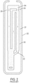
- FIG. 2 A schematic view of such a mold structure is shown in FIG. 2 .
- the ceramic core 200 is assembled inside two die halves which form a space or void therebetween that defines the resulting metal portions of the blade. Wax is injected into the assembled dies to fill the void and surround the ceramic core encapsulated therein. The two die halves are split apart and removed from the molded wax.
- the molded wax has the precise configuration of the desired blade and is then coated with a ceramic material to form a surrounding ceramic shell 202. Then, the wax is melted and removed from the shell 202 leaving a corresponding void or space 201 between the ceramic shell 202 and the internal ceramic core 200 and tip plenum 204. Molten superalloy metal is then poured into the shell to fill the void therein and again encapsulate the ceramic core 200 and tip plenum 204 contained in the shell 202. The molten metal is cooled and solidifies, and then the external shell 202 and internal core 200 and tip plenum 204 are suitably removed leaving behind the desired metallic turbine blade in which the internal cooling passages are found. In order to provide a pathway for removing ceramic core material via a leaching process, a ball chute 203 and tip pins 205 are provided, which upon leaching form a ball chute and tip holes within the turbine blade that must subsequently brazed shut.
- the cast turbine blade may then undergo additional post-casting modifications, such as but not limited to drilling of suitable rows of film cooling holes through the sidewalls of the airfoil as desired for providing outlets for the internally channeled cooling air which then forms a protective cooling air film or blanket over the external surface of the airfoil during operation in the gas turbine engine.
- additional post-casting modifications such as but not limited to drilling of suitable rows of film cooling holes through the sidewalls of the airfoil as desired for providing outlets for the internally channeled cooling air which then forms a protective cooling air film or blanket over the external surface of the airfoil during operation in the gas turbine engine.
- the ball chute 203 of the ceramic core 200 forms a passageway that is later brazed shut to provide the desired pathway of air through the internal voids of the cast turbine blade.
- these post-casting modifications are limited and given the ever increasing complexity of turbine engines and the recognized efficiencies of certain cooling circuits inside turbine blades, more complicated and intricate internal geometries are required. While investment casting is capable of manufacturing these parts
- Cooling passages are proposed in the '151 patent that include staggered vertical cavities joined by short cylinders, the length of which is nearly the same as its diameter.
- a superalloy turbine blade is then formed in the core-shell mold using known techniques disclosed in the '151 patent. After a turbine blade is cast in one of these core-shell molds, the mold is removed to reveal a cast superalloy turbine blade.
- US 2008/080979 discloses an airfoil is disclosed having at least first and second cast, axiallystacked internal airflow cooling circuits.
- US 5 370 499 discloses a turbine airfoil has a mesh cooling hole arrangement which includes first and second pluralities of cooling holes extending between internal and external surfaces of an airfoil side wall at least at a pressure side and extending from an internal chamber to the airfoil exterior.
- US 2008/006384 discloses an investment casting pattern component has a spine and a number of tines extending from the spine.
- US 8 851 151 discloses a system for producing cast components from molten metal.
- US 6 117 612 discloses photocurable ceramic resins having solids loadings in excess of 40 volume percent and a viscosity of less than 3000 mPaxs are suitable for multi-layer fabrication of green ceramic parts by stereolithography.
- US 2010/0028645 A1 discloses an apparatus comprising a green article having a part defining portion and a firing support portion each of the portions formed of a plurality of layers coupled together by a sacrificial polymer binder, and each of the plurality of layers includes a particulate material held together by the sacrificial polymer binder; and the portions having a similar thermal shrinkage rate.
- the invention is defined by the appended claims.
- the invention relates to a method of making a ceramic casting mold in accordance with claim 1.
- the invention relates to a method of preparing a cast component in accordance with claim 5.
- the cast component is a turbine blade or stator vane.
- the turbine blade or stator vane is used in a gas turbine engine in, for example, an aircraft engine or power generation.
- the turbine blade or stator vane is preferably a single crystal cast turbine blade or stator vane having a cooling hole pattern defined by the ceramic filaments mentioned above.
- the filaments join the core portion and shell portion where each filament spans between the core and shell, the filaments having a cross sectional area ranging from 0.01 to 2 mm 2 .
- the large number of filaments used to form a cooling hole pattern may provide sufficient strength to support the tip core. If the tip filaments are made to support tip plenum core, they may be made larger, i.e., >2 mm cross section area, and a much lower number of filaments, or a single filament, could be used. Although two to four of these larger filaments is a desirable number. After casting, any holes or notches remaining in the tip plenum sidewalls as a result of the filaments may be brazed shut or incorporated into the turbine blade or stator vane design, or the filaments may be placed outside the finish machined shape of the component to prevent the need for this.
- the present invention provides a preferred method for making cast metal parts, and preferably those cast metal parts used in the manufacture of jet aircraft engines. Specifically, the production of single crystal, nickel-based superalloy cast parts such as turbine blades, vanes, and shroud components can be advantageously produced in accordance with this invention. However, other cast metal components may be prepared using the techniques and integrated ceramic molds of the present invention.
- the integrated core-shell casting mold of the present invention is manufactured using direct light processing (DLP).
- DLP differs from the above discussed powder bed and SLA processes in that the light curing of the polymer occurs through a window at the bottom of a resin tank that projects light upon a build platform that is raised as the process is conducted. With DLP an entire layer of cured polymer is produced simultaneously, and the need to scan a pattern using a laser is eliminated. Further, the polymerization occurs between the underlying window and the last cured layer of the object being built.
- the underlying window provides support allowing thin filaments of material to be produced without the need for a separate support structure. In other words, producing a thin filament of material bridging two portions of the build object is difficult and was typically avoided in the prior art.
- the ' 151 patent discussed above in the background section of this application used vertical plate structures connected with short cylinders, the length of which was on the order of their diameter. Staggered vertical cavities are necessitated by the fact that the powder bed and SLA techniques disclosed in the '151 patent require vertically supported ceramic structures and the techniques are incapable of reliably producing filaments.
- the available resolution within a powder bed is on the order of 1/8" making the production of traditional cooling holes impracticable.
- round cooling holes generally have a diameter of less than 2 mm corresponding to a cooling hole area below 3.2 mm 2 . Production of a hole of such dimensions requires a resolution far below the size of the actual hole given the need to produce the hole from several voxels.
- the apparatus includes a tank 404 having at least one translucent bottom portion 406 covering at least a portion of the exposure unit 410.
- the exposure unit 410 comprises a light source and modulator with which the intensity can be adjusted position-selectively under the control of a control unit, in order to produce an exposure field on the tank bottom 406 with the geometry desired for the layer currently to be formed.
- a production platform 412 is provided above the tank 404; it is supported by a lifting mechanism (not shown) so that it is held in a height-adjustable way over the tank bottom 406 in the region above the exposure unit 410.
- the production platform 412 may likewise be transparent or translucent in order that light can be shone in by a further exposure unit above the production platform in such a way that, at least when forming the first layer on the lower side of the production platform 412, it can also be exposed from above so that the layer cured first on the production platform adheres thereto with even greater reliability.
- the tank 404 contains a filling of highly viscous photopolymerizable material 420.
- the material level of the filling is much higher than the thickness of the layers which are intended to be defined for position-selective exposure.
- the following procedure is adopted.
- the production platform 412 is lowered by the lifting mechanism in a controlled way so that (before the first exposure step) its lower side is immersed in the filling of photopolymerizable material 420 and approaches the tank bottom 406 to such an extent that precisely the desired layer thickness ⁇ (see FIG. 5 ) remains between the lower side of the production platform 412 and the tank bottom 406.
- the desired position-selective layer exposure is carried out for this layer, in order to cure it in the desired shape.
- exposure from above may also take place through the transparent or translucent production platform 412, so that reliable and complete curing takes place particularly in the contact region between the lower side of the production platform 412 and the photopolymerizable material, and therefore good adhesion of the first layer to the production platform 412 is ensured.
- the production platform is raised again by means of the lifting mechanism.
- an elongate mixing element 432 is moved through the filling of photopolymerizable material 420 in the tank.
- the mixing element 432 comprises an elongate wire which is tensioned between two support arms 430 mounted movably on the side walls of the tank 404.
- the support arms 430 may be mounted movably in guide slots 434 in the side walls of the tank 404, so that the wire 432 tensioned between the support arms 430 can be moved relative to the tank 404, parallel to the tank bottom 406, by moving the support arms 430 in the guide slots 434.
- the elongate mixing element 432 has dimensions, and its movement is guided relative to the tank bottom, such that the upper edge of the elongate mixing element 432 remains below the material level of the filling of photopolymerizable material 420 in the tank outside the exposed region. As can be seen in the sectional view of FIG. 8 , the mixing element 432 is below the material level in the tank over the entire length of the wire, and only the support arms 430 protrude beyond the material level in the tank.
- the effect of arranging the elongate mixing element below the material level in the tank 404 is not that the elongate mixing element 432 substantially moves material in front of it during its movement relative to the tank through the exposed region, but rather this material flows over the mixing element 432 while executing a slight upward movement.
- FIG. 7 The movement of the mixing element 432 from the position shown in FIG. 6 , to, for example, a new position in the direction indicated by the arrow A, is shown in FIG. 7 . It has been found that by this type of action on the photopolymerizable material in the tank, the material is effectively stimulated to flow back into the material-depleted exposed region between the production platform 412 and the exposure unit 410.
- the movement of the elongate mixing element 432 relative to the tank may firstly, with a stationary tank 404, be carried out by a linear drive which moves the support arms 430 along the guide slots 434 in order to achieve the desired movement of the elongate mixing element 432 through the exposed region between the production platform 412 and the exposure unit 410.
- the tank bottom 406 has recesses 406' on both sides.
- the support arms 430 project with their lower ends into these recesses 406'. This makes it possible for the elongate mixing element 432 to be held at the height of the tank bottom 406, without interfering with the movement of the lower ends of the support arms 430 through the tank bottom 406.
- the tank may be positioned on a rotatable platform.
- the tank may be rotated relative to the platform and light source to provide a fresh layer of viscous polymer in which to dip the build platform for building the successive layers.
- FIG. 9 shows a schematic side view of an integrated core-shell mold with hollow filaments 902 connecting the core 900 and shell portions 901.
- the hollow filaments generally have an inside diameter 906 and an outside diameter 907.
- the hollow filaments 902 are provided in a large quantity consistent with formation of a pattern of effusion cooling holes in the surface of a turbine blade, the need for a ball chute structure as shown in FIG. 2 may be eliminated.
- the hollow tip pins 905 connecting the hollow tip plenum core 904 to the hollow core 900 are retained. After removal of the ceramic mold, tip holes exist between the hollow core 900 and hollow tip plenum core 904 that may be subsequently brazed shut.
- the hollow tip pins 905 may be eliminated by connecting the tip plenum core 904 to the shell 901 using additional hollow filaments, avoiding the need to braze shut tip holes connecting the core cavity with the tip plenum after casting is complete.
- the mold core 900 may also be a hollow mold core in accordance with certain aspects of the invention.
- the hollow core has an inside diameter 908 and an outside diameter 909.
- the cross sectional area defined by the inner diameter is greater than 80% of the cross sectional area of the outer diameter, preferably greater than 90%.
- the wall thickness of the hollow core is equivalent to that of the cylinder where the inner diameter is greater than 80% of the cross sectional area of the outer diameter.
- the filaments 902 are preferably cylindrical or oval shape but may be curved or non-linear. Their exact dimensions may be varied according to a desired film cooling scheme for a particular cast metal part.
- cooling holes may have a cross sectional area ranging from 0.01 to 2 mm 2 .
- the cross sectional area may range from 0.01 to 0.15 mm 2 , more preferably from 0.05 to 0.1 mm 2 , and most preferably about 0.07 mm 2 .
- the cooling holes may have a cross sectional area ranging from 0.05 to 0.2 mm 2 , more preferably 0.1 to 0.18 mm 2 , and most preferably about 0.16 mm 2 .
- the spacing of the cooling holes is typically a multiple of the diameter of the cooling holes ranging from 2 ⁇ to 10 ⁇ the diameter of the cooling holes, most preferably about 4-7 ⁇ the diameter of the holes.
- the length of the filament 902 is dictated by the thickness of the cast component, e.g., turbine blade or stator vane wall thickness, and the angle at which the cooling hole is disposed relative to the surface of the cast component.
- the typical lengths range from 0.5 to 5 mm, more preferably between 0.7 to 1 mm, and most preferably about 0.9 mm.
- the angle at which a cooling hole is disposed is approximately 5 to 35° relative to the surface, more preferably between 10 to 20°, and most preferably approximately 12°. It should be appreciated that the methods of casting according to the present invention allow for formation of cooling holes having a lower angle relative to the surface of the cast component than currently available using conventional machining techniques.
- the cross-sectional area defined by the inner diameter 906 of the hollow filament should be at least 50% of the outer diameter 907 of the filament.
- this cross-sectional area can be increased, for example, to 60%, 70%, or 75% of the outer diameter of the filament.
- one or more of the filaments connecting the core 900 and the shell 901 of the turbine blade may be solid.
- FIG. 10 shows the integrated core-shell mold of FIG. 9 filled with cast metal 1000, such as a nickel based alloy, i.e., Inconel.
- the metal is filled into cavity 911, while the hollow core cavity 910 is left unfilled.
- the ceramic core 900, shell 901 and filaments 902 are removed using a combination of chemical and mechanical processes.
- the hollow nature of the core 900 and filaments 902 allows for removal of the ceramic mold while minimizing the amount of chemical leaching needed. This saves time and reduces the potential for errors in the manufacturing process.
- the resulting cast object is a turbine blade having a cooling hole pattern in the surface of the blade.
- FIGS. 9-10 provide a cross sectional view showing cooling holes at the leading and trailing edge of the turbine blade, that additional cooling holes may be provided where desired including on the sides of the turbine blades or any other location desired.
- the present invention may be used to form cooling holes within the casting process in any particular design. In other words, one would be able to produce conventional cooling holes in any pattern where drilling was used previously to form the cooling holes.
- the present invention will allow for cooling hole patterns previously unattainable due to the limitations of conventional technologies for creating cooling holes within cast components, i.e., drilling.
- FIG. 11 shows a side view of an integrated core-shell mold according to an embodiment of the present invention.
- the mold has a hollow ceramic core 1100 and a ceramic shell 1101.
- the core 1100 and shell 1101 are connected by filaments 1102.
- the filaments 1102 are shown as solid filaments that end up resulting in holes in the ultimate case object.
- the filaments 1102 may be made hollow as described above. Because of the relatively small size of the filaments 1102 relative to the core 1100, the filaments may be made solid and the core hollow as shown in FIG. 11 .
- the hollow core provides a cavity 910 that can subsequently be filled with metal. Because the wall thickness of the hollow core is controlled (as opposed to a solid core), subsequent leaching of the ceramic core can be expedited.
- the filaments 1102 may be solid filaments as shown in FIGS. 11 and 12 , or hollow filaments as shown in FIGS. 9-10 .
- cooling hole filaments may be provided to connect the tip plenum core to the shell in a sufficient quantity to hold the tip plenum core in place during the metal casting step.
- the core-shell mold may be cured and/or fired depending upon the requirements of the ceramic core photopolymer material.
- Molten metal may be poured into the mold to form a cast object in the shape and having the features provided by the integrated core-shell mold.
- the molten metal is preferably a superalloy metal that is formed into a single crystal superalloy turbine blade or stator vane using techniques known to be used with conventional investment casting molds.
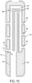
- FIG. 12 shows the ceramic integrated mold 1100/1101 of FIG. 11 filled with cast metal 1200, such as a nickel based alloy, i.e., Inconel.
- FIG. 13 shows a cast turbine blade 1300 with cooling holes 1301, 1302 connecting the blade surface to the hollow core 1303 of the blade.
Landscapes
- Engineering & Computer Science (AREA)
- Mechanical Engineering (AREA)
- Chemical & Material Sciences (AREA)
- Materials Engineering (AREA)
- Manufacturing & Machinery (AREA)
- Physics & Mathematics (AREA)
- Optics & Photonics (AREA)
- General Physics & Mathematics (AREA)
- Ceramic Engineering (AREA)
- Molds, Cores, And Manufacturing Methods Thereof (AREA)
Description
- The present disclosure generally relates to investment casting core-shell mold components and processes utilizing these components. The core-shell mold made in accordance with the present invention includes integrated hollow ceramic core tubes that are used to define at least a portion of an interior region of a cast article. In the case of a turbine blade, the tubes may define the inner core region, and/or may define a portion of a ceramic core filament for producing a cooling hole in the turbine blade. The use of sufficient ceramic filaments between core and shell to both locate and provide leaching pathways for the core serpentine also enables the elimination of ball braze chutes. Ceramic filaments between the tip plenum core and the shell may also be provided to support a floating tip plenum, eliminating the need for traditional tip pins, and their subsequent closure by brazing. The integrated core-shell molds provide useful properties in casting operations, such as in the casting of superalloys used to make turbine blades and stator vanes for jet aircraft engines or power generation turbine components.
- Many modern engines and next generation turbine engines require components and parts having intricate and complex geometries, which require new types of materials and manufacturing techniques. Conventional techniques for manufacturing engine parts and components involve the laborious process of investment or lost-wax casting. One example of investment casting involves the manufacture of a typical rotor blade used in a gas turbine engine. A turbine blade typically includes hollow airfoils that have radial channels extending along the span of a blade having at least one or more inlets for receiving pressurized cooling air during operation in the engine. The various cooling passages in a blade typically include a serpentine channel disposed in the middle of the airfoil between the leading and trailing edges. The airfoil typically includes inlets extending through the blade for receiving pressurized cooling air, which include local features such as short turbulator ribs or pins for increasing the heat transfer between the heated sidewalls of the airfoil and the internal cooling air.
- The manufacture of these turbine blades, typically from high strength, superalloy metal materials, involves numerous steps shown in
FIG. 1 . First, a precision ceramic core is manufactured to conform to the intricate cooling passages desired inside the turbine blade. A precision die or mold is also created which defines the precise 3-D external surface of the turbine blade including its airfoil, platform, and integral dovetail. A schematic view of such a mold structure is shown inFIG. 2 . Theceramic core 200 is assembled inside two die halves which form a space or void therebetween that defines the resulting metal portions of the blade. Wax is injected into the assembled dies to fill the void and surround the ceramic core encapsulated therein. The two die halves are split apart and removed from the molded wax. The molded wax has the precise configuration of the desired blade and is then coated with a ceramic material to form a surroundingceramic shell 202. Then, the wax is melted and removed from theshell 202 leaving a corresponding void orspace 201 between theceramic shell 202 and the internalceramic core 200 and tip plenum 204. Molten superalloy metal is then poured into the shell to fill the void therein and again encapsulate theceramic core 200 and tip plenum 204 contained in theshell 202. The molten metal is cooled and solidifies, and then theexternal shell 202 andinternal core 200 and tip plenum 204 are suitably removed leaving behind the desired metallic turbine blade in which the internal cooling passages are found. In order to provide a pathway for removing ceramic core material via a leaching process, aball chute 203 andtip pins 205 are provided, which upon leaching form a ball chute and tip holes within the turbine blade that must subsequently brazed shut. - The cast turbine blade may then undergo additional post-casting modifications, such as but not limited to drilling of suitable rows of film cooling holes through the sidewalls of the airfoil as desired for providing outlets for the internally channeled cooling air which then forms a protective cooling air film or blanket over the external surface of the airfoil during operation in the gas turbine engine. After the turbine blade is removed from the ceramic mold, the
ball chute 203 of theceramic core 200 forms a passageway that is later brazed shut to provide the desired pathway of air through the internal voids of the cast turbine blade. However, these post-casting modifications are limited and given the ever increasing complexity of turbine engines and the recognized efficiencies of certain cooling circuits inside turbine blades, more complicated and intricate internal geometries are required. While investment casting is capable of manufacturing these parts, positional precision and intricate internal geometries become more complex to manufacture using these conventional manufacturing processes. Accordingly, it is desired to provide an improved casting method for three dimensional components having intricate internal voids. - Methods for using 3-D printing to produce a ceramic core-shell mold are described in
U.S. Patent No. 8,851,151 assigned to Rolls-Royce Corporation . The methods for making the molds include powder bed ceramic processes such as disclosedU.S. Patent No. 5,387,380 assigned to Massachusetts Institute of Technology , and selective laser activation (SLA) such as disclosed inU.S. Patent No. 5,256,340 assigned to 3D Systems, Inc . The ceramic core-shell molds according to the '151 patent are limited by the printing resolution capabilities of these processes. As shown inFIG. 3 , thecore portion 301 andshell portion 302 of the integrated core-shell mold is held together via a series oftie structures 303 provided at the bottom edge of the mold. Cooling passages are proposed in the '151 patent that include staggered vertical cavities joined by short cylinders, the length of which is nearly the same as its diameter. A superalloy turbine blade is then formed in the core-shell mold using known techniques disclosed in the '151 patent. After a turbine blade is cast in one of these core-shell molds, the mold is removed to reveal a cast superalloy turbine blade. - There remains a need to prepare ceramic core-shell molds produced using higher resolution methods that are capable of providing fine detail cast features in the end-product of the casting process.
-
US 2008/080979 discloses an airfoil is disclosed having at least first and second cast, axiallystacked internal airflow cooling circuits. -
US 5 370 499 discloses a turbine airfoil has a mesh cooling hole arrangement which includes first and second pluralities of cooling holes extending between internal and external surfaces of an airfoil side wall at least at a pressure side and extending from an internal chamber to the airfoil exterior. -
US 2008/006384 discloses an investment casting pattern component has a spine and a number of tines extending from the spine. -
US 8 851 151 discloses a system for producing cast components from molten metal. -
US 6 117 612 discloses photocurable ceramic resins having solids loadings in excess of 40 volume percent and a viscosity of less than 3000 mPaxs are suitable for multi-layer fabrication of green ceramic parts by stereolithography. -
US 2010/0028645 A1 discloses an apparatus comprising a green article having a part defining portion and a firing support portion each of the portions formed of a plurality of layers coupled together by a sacrificial polymer binder, and each of the plurality of layers includes a particulate material held together by the sacrificial polymer binder; and the portions having a similar thermal shrinkage rate. - The invention is defined by the appended claims. In a first aspect, the invention relates to a method of making a ceramic casting mold in accordance with
claim 1. - In another aspect, the invention relates to a method of preparing a cast component in accordance with claim 5.
- In one aspect, the cast component is a turbine blade or stator vane. Preferably the turbine blade or stator vane is used in a gas turbine engine in, for example, an aircraft engine or power generation. The turbine blade or stator vane is preferably a single crystal cast turbine blade or stator vane having a cooling hole pattern defined by the ceramic filaments mentioned above. Preferably, the filaments join the core portion and shell portion where each filament spans between the core and shell, the filaments having a cross sectional area ranging from 0.01 to 2 mm2.
- The large number of filaments used to form a cooling hole pattern may provide sufficient strength to support the tip core. If the tip filaments are made to support tip plenum core, they may be made larger, i.e., >2 mm cross section area, and a much lower number of filaments, or a single filament, could be used. Although two to four of these larger filaments is a desirable number. After casting, any holes or notches remaining in the tip plenum sidewalls as a result of the filaments may be brazed shut or incorporated into the turbine blade or stator vane design, or the filaments may be placed outside the finish machined shape of the component to prevent the need for this.
-
-
FIG. 1 is a flow diagram showing the steps for conventional investment casting. -
FIG. 2 is a schematic diagram showing an example of a conventional scheme for a core-shell mold with ball chute prepared by a conventional process. -
FIG. 3 shows a perspective view of a prior art integrated core-shell mold with ties connecting the core and shell portions. -
FIGS. 4, 5 ,6 and7 show schematic lateral sectional views of a device for carrying out successive phases of the method sequence for direct light processing (DLP). -
FIG. 8 shows a schematic sectional view along the line A-A ofFIG. 7 . -
FIG. 9 shows a side view of an integrated core-shell mold with filaments connecting the core and shell portions. -
FIG. 10 . show the integrated core-shell mold ofFIG. 9 filled with cast metal. -
FIG. 11 shows a side view of an integrated core-shell mold according to an embodiment of the present invention. -
FIG. 12 shows a side view of a superalloy-filled integrated core-shell mold according to an embodiment of the present invention. -
FIG. 13 shows the cast turbine blade made in accordance with the invention. - The detailed description set forth below in connection with the appended drawings is intended as a description of various configurations and is not intended to represent the only configurations in which the concepts described herein may be practiced. The detailed description includes specific details for the purpose of providing a thorough understanding of various concepts. However, it will be apparent to those skilled in the art that these concepts may be practiced without these specific details. For example, the present invention provides a preferred method for making cast metal parts, and preferably those cast metal parts used in the manufacture of jet aircraft engines. Specifically, the production of single crystal, nickel-based superalloy cast parts such as turbine blades, vanes, and shroud components can be advantageously produced in accordance with this invention. However, other cast metal components may be prepared using the techniques and integrated ceramic molds of the present invention.
- The present inventors recognized that prior processes known for making integrated core-shell molds lacked the fine resolution capability necessary to print filaments extending between the core and shell portion of the mold of sufficiently small size and quantity to result in effusion cooling holes in the finished turbine blade. In the case of earlier powder bed processes, such as disclosed in
U.S. Patent No. 5,387,380 assigned to Massachusetts Institute of Technology , the action of the powder bed recoater arm precludes formation of sufficiently fine filaments extending between the core and shell to provide an effusion cooling hole pattern in the cast part. Other known techniques such as selective laser activation (SLA) such as disclosed inU.S. Patent No. 5,256,340 assigned to 3D Systems, Inc. that employ a top-down irradiation technique may be utilized in producing an integrated core-shell mold in accordance with the present invention. However, the available printing resolution of these systems significantly limit the ability to make filaments of sufficiently small size to serve as effective cooling holes in the cast final product. - The integrated core-shell casting mold of the present invention is manufactured using direct light processing (DLP). DLP differs from the above discussed powder bed and SLA processes in that the light curing of the polymer occurs through a window at the bottom of a resin tank that projects light upon a build platform that is raised as the process is conducted. With DLP an entire layer of cured polymer is produced simultaneously, and the need to scan a pattern using a laser is eliminated. Further, the polymerization occurs between the underlying window and the last cured layer of the object being built. The underlying window provides support allowing thin filaments of material to be produced without the need for a separate support structure. In other words, producing a thin filament of material bridging two portions of the build object is difficult and was typically avoided in the prior art. For example, the ' 151 patent discussed above in the background section of this application used vertical plate structures connected with short cylinders, the length of which was on the order of their diameter. Staggered vertical cavities are necessitated by the fact that the powder bed and SLA techniques disclosed in the '151 patent require vertically supported ceramic structures and the techniques are incapable of reliably producing filaments. In addition, the available resolution within a powder bed is on the order of 1/8" making the production of traditional cooling holes impracticable. For example, round cooling holes generally have a diameter of less than 2 mm corresponding to a cooling hole area below 3.2 mm2. Production of a hole of such dimensions requires a resolution far below the size of the actual hole given the need to produce the hole from several voxels. This resolution is simply not available in a powder bed process. Similarly, stereolithography is limited in its ability to produce such filaments due to lack of support and resolution problems associated with laser scattering. But the fact that DLP exposes the entire length of the filament and supports it between the window and the build plate enables producing sufficiently thin filaments spanning the entire length between the core and shell to form a ceramic object having the desired cooling hole pattern. Although powder bed and SLA may be used to produce filaments, their ability to produce sufficiently fine filaments as discussed above is limited.
- One suitable DLP process is disclosed in
U.S. Patent No. 9,079,357 assigned to Ivoclar Vivadent AG and Technische Universitat Wien WO 2010/045950 A1 andUS 2011310370 , which are discussed below with reference toFIGS. 4-8 . The apparatus includes atank 404 having at least onetranslucent bottom portion 406 covering at least a portion of theexposure unit 410. Theexposure unit 410 comprises a light source and modulator with which the intensity can be adjusted position-selectively under the control of a control unit, in order to produce an exposure field on thetank bottom 406 with the geometry desired for the layer currently to be formed. - Opposite the
exposure unit 410, aproduction platform 412 is provided above thetank 404; it is supported by a lifting mechanism (not shown) so that it is held in a height-adjustable way over thetank bottom 406 in the region above theexposure unit 410. Theproduction platform 412 may likewise be transparent or translucent in order that light can be shone in by a further exposure unit above the production platform in such a way that, at least when forming the first layer on the lower side of theproduction platform 412, it can also be exposed from above so that the layer cured first on the production platform adheres thereto with even greater reliability. - The
tank 404 contains a filling of highly viscousphotopolymerizable material 420. The material level of the filling is much higher than the thickness of the layers which are intended to be defined for position-selective exposure. In order to define a layer of photopolymerizable material, the following procedure is adopted. Theproduction platform 412 is lowered by the lifting mechanism in a controlled way so that (before the first exposure step) its lower side is immersed in the filling ofphotopolymerizable material 420 and approaches thetank bottom 406 to such an extent that precisely the desired layer thickness Δ (seeFIG. 5 ) remains between the lower side of theproduction platform 412 and thetank bottom 406. During this immersion process, photopolymerizable material is displaced from the gap between the lower side of theproduction platform 412 and thetank bottom 406. After the layer thickness Δ has been set, the desired position-selective layer exposure is carried out for this layer, in order to cure it in the desired shape. Particularly when forming the first layer, exposure from above may also take place through the transparent ortranslucent production platform 412, so that reliable and complete curing takes place particularly in the contact region between the lower side of theproduction platform 412 and the photopolymerizable material, and therefore good adhesion of the first layer to theproduction platform 412 is ensured. After the layer has been formed, the production platform is raised again by means of the lifting mechanism. - These steps are subsequently repeated several times, the distance from the lower side of the
layer 422 formed last to thetank bottom 406 respectively being set to the desired layer thickness Δ and the next layer thereupon being cured position-selectively in the desired way. - After the
production platform 412 has been raised following an exposure step, there is a material deficit in the exposed region as indicated inFIG. 6 . This is because after curing the layer set with the thickness Δ, the material of this layer is cured and raised with the production platform and the part of the shaped body already formed thereon. The photopolymerizable material therefore missing between the lower side of the already formed shaped body part and thetank bottom 406 must be filled from the filling ofphotopolymerizable material 420 from the region surrounding the exposed region. Owing to the high viscosity of the material, however, it does not flow by itself back into the exposed region between the lower side of the shaped body part and the tank bottom, so that material depressions or "holes" can remain here. - In order to replenish the exposure region with photopolymerizable material, an
elongate mixing element 432 is moved through the filling ofphotopolymerizable material 420 in the tank. In the exemplary embodiment represented inFIGS. 4 to 8 , the mixingelement 432 comprises an elongate wire which is tensioned between twosupport arms 430 mounted movably on the side walls of thetank 404. Thesupport arms 430 may be mounted movably inguide slots 434 in the side walls of thetank 404, so that thewire 432 tensioned between thesupport arms 430 can be moved relative to thetank 404, parallel to thetank bottom 406, by moving thesupport arms 430 in theguide slots 434. Theelongate mixing element 432 has dimensions, and its movement is guided relative to the tank bottom, such that the upper edge of theelongate mixing element 432 remains below the material level of the filling ofphotopolymerizable material 420 in the tank outside the exposed region. As can be seen in the sectional view ofFIG. 8 , the mixingelement 432 is below the material level in the tank over the entire length of the wire, and only thesupport arms 430 protrude beyond the material level in the tank. The effect of arranging the elongate mixing element below the material level in thetank 404 is not that theelongate mixing element 432 substantially moves material in front of it during its movement relative to the tank through the exposed region, but rather this material flows over the mixingelement 432 while executing a slight upward movement. The movement of the mixingelement 432 from the position shown inFIG. 6 , to, for example, a new position in the direction indicated by the arrow A, is shown inFIG. 7 . It has been found that by this type of action on the photopolymerizable material in the tank, the material is effectively stimulated to flow back into the material-depleted exposed region between theproduction platform 412 and theexposure unit 410. - The movement of the
elongate mixing element 432 relative to the tank may firstly, with astationary tank 404, be carried out by a linear drive which moves thesupport arms 430 along theguide slots 434 in order to achieve the desired movement of theelongate mixing element 432 through the exposed region between theproduction platform 412 and theexposure unit 410. As shown inFIG. 8 , thetank bottom 406 has recesses 406' on both sides. Thesupport arms 430 project with their lower ends into these recesses 406'. This makes it possible for theelongate mixing element 432 to be held at the height of thetank bottom 406, without interfering with the movement of the lower ends of thesupport arms 430 through thetank bottom 406. - Other alternative methods of DLP may be used to prepare the integrated core-shell molds of the present invention. For example, the tank may be positioned on a rotatable platform. When the workpiece is withdrawn from the viscous polymer between successive build steps, the tank may be rotated relative to the platform and light source to provide a fresh layer of viscous polymer in which to dip the build platform for building the successive layers.
-
FIG. 9 shows a schematic side view of an integrated core-shell mold withhollow filaments 902 connecting thecore 900 andshell portions 901. The hollow filaments generally have aninside diameter 906 and anoutside diameter 907. By printing the ceramic mold using the above DLP printing process, the mold can be made in a way that allows the point of connections between the core and shell to be provided through thehollow filaments 902. Once the core-shell mold is printed, it may be subject to a post-heat treatment step to cure the printed ceramic polymer material. The cured ceramic mold may then be used similar to the traditional casting process used in the production of superalloy turbine blades. Notably because thehollow filaments 902 are provided in a large quantity consistent with formation of a pattern of effusion cooling holes in the surface of a turbine blade, the need for a ball chute structure as shown inFIG. 2 may be eliminated. In this embodiment, the hollow tip pins 905 connecting the hollowtip plenum core 904 to thehollow core 900 are retained. After removal of the ceramic mold, tip holes exist between thehollow core 900 and hollowtip plenum core 904 that may be subsequently brazed shut. However, the hollow tip pins 905 may be eliminated by connecting thetip plenum core 904 to theshell 901 using additional hollow filaments, avoiding the need to braze shut tip holes connecting the core cavity with the tip plenum after casting is complete. - The
mold core 900 may also be a hollow mold core in accordance with certain aspects of the invention. The hollow core has aninside diameter 908 and anoutside diameter 909. In general, the cross sectional area defined by the inner diameter is greater than 80% of the cross sectional area of the outer diameter, preferably greater than 90%. In the case where the mold core does not have a cylindrical shape, the wall thickness of the hollow core is equivalent to that of the cylinder where the inner diameter is greater than 80% of the cross sectional area of the outer diameter. - The
filaments 902 are preferably cylindrical or oval shape but may be curved or non-linear. Their exact dimensions may be varied according to a desired film cooling scheme for a particular cast metal part. For example cooling holes may have a cross sectional area ranging from 0.01 to 2 mm2. In a turbine blade or stator vane, the cross sectional area may range from 0.01 to 0.15 mm2, more preferably from 0.05 to 0.1 mm2, and most preferably about 0.07 mm2. In the case of a vane, the cooling holes may have a cross sectional area ranging from 0.05 to 0.2 mm2, more preferably 0.1 to 0.18 mm2, and most preferably about 0.16 mm2. The spacing of the cooling holes is typically a multiple of the diameter of the cooling holes ranging from 2× to 10× the diameter of the cooling holes, most preferably about 4-7× the diameter of the holes. - The length of the
filament 902 is dictated by the thickness of the cast component, e.g., turbine blade or stator vane wall thickness, and the angle at which the cooling hole is disposed relative to the surface of the cast component. The typical lengths range from 0.5 to 5 mm, more preferably between 0.7 to 1 mm, and most preferably about 0.9 mm. The angle at which a cooling hole is disposed is approximately 5 to 35° relative to the surface, more preferably between 10 to 20°, and most preferably approximately 12°. It should be appreciated that the methods of casting according to the present invention allow for formation of cooling holes having a lower angle relative to the surface of the cast component than currently available using conventional machining techniques. - The cross-sectional area defined by the
inner diameter 906 of the hollow filament should be at least 50% of theouter diameter 907 of the filament. For thinner tubes this cross-sectional area can be increased, for example, to 60%, 70%, or 75% of the outer diameter of the filament. In some cases one or more of the filaments connecting thecore 900 and theshell 901 of the turbine blade may be solid. -
FIG. 10 shows the integrated core-shell mold ofFIG. 9 filled withcast metal 1000, such as a nickel based alloy, i.e., Inconel. The metal is filled intocavity 911, while thehollow core cavity 910 is left unfilled. After casting, theceramic core 900,shell 901 andfilaments 902 are removed using a combination of chemical and mechanical processes. The hollow nature of thecore 900 andfilaments 902 allows for removal of the ceramic mold while minimizing the amount of chemical leaching needed. This saves time and reduces the potential for errors in the manufacturing process. - Upon leaching of the ceramic core-shell, the resulting cast object is a turbine blade having a cooling hole pattern in the surface of the blade. It should be appreciated that although
FIGS. 9-10 provide a cross sectional view showing cooling holes at the leading and trailing edge of the turbine blade, that additional cooling holes may be provided where desired including on the sides of the turbine blades or any other location desired. In particular, the present invention may be used to form cooling holes within the casting process in any particular design. In other words, one would be able to produce conventional cooling holes in any pattern where drilling was used previously to form the cooling holes. However, the present invention will allow for cooling hole patterns previously unattainable due to the limitations of conventional technologies for creating cooling holes within cast components, i.e., drilling. -
FIG. 11 shows a side view of an integrated core-shell mold according to an embodiment of the present invention. In this embodiment, the mold has a hollowceramic core 1100 and aceramic shell 1101. Thecore 1100 andshell 1101 are connected byfilaments 1102. Thefilaments 1102 are shown as solid filaments that end up resulting in holes in the ultimate case object. Thefilaments 1102 may be made hollow as described above. Because of the relatively small size of thefilaments 1102 relative to thecore 1100, the filaments may be made solid and the core hollow as shown inFIG. 11 . The hollow core provides acavity 910 that can subsequently be filled with metal. Because the wall thickness of the hollow core is controlled (as opposed to a solid core), subsequent leaching of the ceramic core can be expedited. As noted above, thefilaments 1102 may be solid filaments as shown inFIGS. 11 and12 , or hollow filaments as shown inFIGS. 9-10 . - After leaching, the resulting holes in the turbine blade from the core print filaments may be brazed shut if desired. Otherwise the holes left by the core print filaments may be incorporated into the design of the internal cooling passages. Alternatively, cooling hole filaments may be provided to connect the tip plenum core to the shell in a sufficient quantity to hold the tip plenum core in place during the metal casting step.
- After printing the core-shell casting mold in accordance with the invention, the core-shell mold may be cured and/or fired depending upon the requirements of the ceramic core photopolymer material. Molten metal may be poured into the mold to form a cast object in the shape and having the features provided by the integrated core-shell mold. In the case of a turbine blade or stator vane, the molten metal is preferably a superalloy metal that is formed into a single crystal superalloy turbine blade or stator vane using techniques known to be used with conventional investment casting molds.
FIG. 12 shows the ceramicintegrated mold 1100/1101 ofFIG. 11 filled withcast metal 1200, such as a nickel based alloy, i.e., Inconel. After metal is filled into the mold, the ceramic mold is removed using a combination of mechanical and chemical processes (i.e., leaching). After leaching, the resulting holes in the turbine blade serve as effusion cooling holes.FIG. 13 shows acast turbine blade 1300 withcooling holes hollow core 1303 of the blade. This written description uses examples to disclose the invention, including the preferred embodiments, and also to enable any person skilled in the art to practice the invention. The patentable scope of the invention is defined by the appended claims.
Claims (5)
- A method for fabricating a ceramic casting mold using direct light processing, DLP, comprising:(a) contacting a cured portion of a workpiece with a liquid ceramic photopolymer;(b) irradiating a portion of the liquid ceramic photopolymer adjacent to the cured portion through a window contacting the liquid ceramic photopolymer;(c) removing the workpiece from the uncured liquid ceramic photopolymer; and(d) repeating steps (a) - (c) until a ceramic casting mold is formed, the ceramic casting mold comprising:(1) a core portion (1100) and a shell portion (1101) with at least one cavity between the core portion (1100) and the shell portion (1101), the at least one cavity defining the shape of a cast component upon casting and removal of the ceramic casting mold, and(2) a plurality of filaments (1102) joining the core portion (1100) and the shell portion (1101) where each filament (1102) spans between the core and shell and defines a hole in the cast component upon removal of the mold, wherein at least a portion of the plurality of filaments (1102) and/or the core portion (1100) is in the shape of a hollow tube.
- The method of any one of claims 1, wherein the outer diameter of the filament (1102) has a cross sectional area ranging from 0.01 to 2 mm2.
- The method of any one of claims 1-2. wherein the filament hollow tube has an inner diameter cross-sectional area that is at least 50% of the cross sectional area of the outer diameter of the filament (1102).
- The method of any one of claims 1-3, wherein the core hollow tube structure has an inner diameter cross-sectional area that is at least 80% of the cross sectional area of the outer diameter of the core portion (1100).
- A method of preparing a cast component comprising:(a) pouring a liquid metal into a ceramic casting mold manufactured in accordance with any of the preceding claims, and solidifying the liquid metal to form the cast component, the ceramic casting mold comprising:(1) a core portion (1100) and a shell portion (1101) with at least one cavity between the core portion (1100) and the shell portion (1101), the at least one cavity defining the shape of a cast component upon casting and removal of the ceramic casting mold, and(2) a plurality of filaments (1102) joining the core portion (1100) and the shell portion (1101) where each filament spans between the core and shell and defines a hole in the cast component, wherein at least a portion of the filament (1102) and/or the core portion (1100) is in the shape of a hollow tube;(b) removing the ceramic casting mold from the cast component by leaching at least a portion of the ceramic core through the holes in the cast component.
Applications Claiming Priority (2)
| Application Number | Priority Date | Filing Date | Title |
|---|---|---|---|
| US15/377,673 US20180161852A1 (en) | 2016-12-13 | 2016-12-13 | Integrated casting core-shell structure with printed tubes for making cast component |
| PCT/US2017/057831 WO2018111404A1 (en) | 2016-12-13 | 2017-10-23 | Integrated casting core-shell structure with printed tubes for making cast component |
Publications (2)
| Publication Number | Publication Date |
|---|---|
| EP3554740A1 EP3554740A1 (en) | 2019-10-23 |
| EP3554740B1 true EP3554740B1 (en) | 2022-03-02 |
Family
ID=60263085
Family Applications (1)
| Application Number | Title | Priority Date | Filing Date |
|---|---|---|---|
| EP17794557.3A Active EP3554740B1 (en) | 2016-12-13 | 2017-10-23 | A method for fabricating a ceramic casting mold |
Country Status (6)
| Country | Link |
|---|---|
| US (1) | US20180161852A1 (en) |
| EP (1) | EP3554740B1 (en) |
| JP (1) | JP7099792B2 (en) |
| CN (1) | CN110072648B (en) |
| CA (1) | CA3045612C (en) |
| WO (1) | WO2018111404A1 (en) |
Families Citing this family (27)
| Publication number | Priority date | Publication date | Assignee | Title |
|---|---|---|---|---|
| PL3086893T3 (en) * | 2013-12-23 | 2020-01-31 | United Technologies Corporation | Lost core structural frame |
| FR3037829B1 (en) * | 2015-06-29 | 2017-07-21 | Snecma | CORE FOR MOLDING A DAWN WITH OVERLAPPED CAVITIES AND COMPRISING A DEDUSISHING HOLE THROUGH A CAVITY PARTLY |
| US10807154B2 (en) * | 2016-12-13 | 2020-10-20 | General Electric Company | Integrated casting core-shell structure for making cast component with cooling holes in inaccessible locations |
| US20180161854A1 (en) * | 2016-12-13 | 2018-06-14 | General Electric Company | Integrated casting core-shell structure |
| US11813669B2 (en) | 2016-12-13 | 2023-11-14 | General Electric Company | Method for making an integrated core-shell structure |
| US20180161853A1 (en) * | 2016-12-13 | 2018-06-14 | General Electric Company | Integrated casting core-shell structure with floating tip plenum |
| US20180161866A1 (en) | 2016-12-13 | 2018-06-14 | General Electric Company | Multi-piece integrated core-shell structure for making cast component |
| US10702958B2 (en) | 2017-02-22 | 2020-07-07 | General Electric Company | Method of manufacturing turbine airfoil and tip component thereof using ceramic core with witness feature |
| US11154956B2 (en) | 2017-02-22 | 2021-10-26 | General Electric Company | Method of repairing turbine component using ultra-thin plate |
| US10625342B2 (en) | 2017-02-22 | 2020-04-21 | General Electric Company | Method of repairing turbine component |
| US10717130B2 (en) | 2017-02-22 | 2020-07-21 | General Electric Company | Method of manufacturing turbine airfoil and tip component thereof |
| US10610933B2 (en) | 2017-02-22 | 2020-04-07 | General Electric Company | Method of manufacturing turbine airfoil with open tip casting and tip component thereof |
| US10391549B2 (en) | 2017-06-28 | 2019-08-27 | General Electric Company | Additively manufactured casting core-shell hybrid mold and ceramic shell |
| US10974312B2 (en) | 2017-06-28 | 2021-04-13 | General Electric Company | Additively manufactured casting core-shell mold with integrated filter and ceramic shell |
| US11173542B2 (en) | 2017-06-28 | 2021-11-16 | General Electric Company | Additively manufactured casting core-shell mold and ceramic shell with variable thermal properties |
| US10391670B2 (en) | 2017-06-28 | 2019-08-27 | General Electric Company | Additively manufactured integrated casting core structure with ceramic shell |
| US11192172B2 (en) | 2017-06-28 | 2021-12-07 | General Electric Company | Additively manufactured interlocking casting core structure with ceramic shell |
| US11377962B2 (en) | 2019-09-05 | 2022-07-05 | General Electric Company | Closure element with extensions for internal passage of component |
| US11813665B2 (en) * | 2020-09-14 | 2023-11-14 | General Electric Company | Methods for casting a component having a readily removable casting core |
| US12535033B2 (en) | 2022-11-01 | 2026-01-27 | General Electric Company | Gas turbine engine |
| US12410753B2 (en) | 2022-11-01 | 2025-09-09 | General Electric Company | Gas turbine engine |
| US12392290B2 (en) | 2022-11-01 | 2025-08-19 | General Electric Company | Gas turbine engine |
| US12196131B2 (en) | 2022-11-01 | 2025-01-14 | General Electric Company | Gas turbine engine |
| US12428992B2 (en) | 2022-11-01 | 2025-09-30 | General Electric Company | Gas turbine engine |
| US12503980B2 (en) | 2022-11-01 | 2025-12-23 | General Electric Company | Gas turbine engine |
| US12121956B1 (en) | 2023-05-22 | 2024-10-22 | General Electric Company | Casting assembly |
| US12540551B1 (en) | 2025-07-01 | 2026-02-03 | General Electric Company | Gas turbine engines including splittered airfoils |
Citations (4)
| Publication number | Priority date | Publication date | Assignee | Title |
|---|---|---|---|---|
| US20100003619A1 (en) * | 2008-05-05 | 2010-01-07 | Suman Das | Systems and methods for fabricating three-dimensional objects |
| US20100028645A1 (en) * | 2008-08-04 | 2010-02-04 | Michael Maguire | Adaptive supports for green state articles and methods of processing thereof |
| US20160221262A1 (en) * | 2008-05-05 | 2016-08-04 | Suman Das | Systems and methods for fabricating three-dimensional objects |
| EP3290186A1 (en) * | 2015-04-28 | 2018-03-07 | Gold Array Technology Beijing LLC | Photo-curing 3d printer and 3d printing method |
Family Cites Families (24)
| Publication number | Priority date | Publication date | Assignee | Title |
|---|---|---|---|---|
| US5256340A (en) | 1988-04-18 | 1993-10-26 | 3D Systems, Inc. | Method of making a three-dimensional object by stereolithography |
| US5387380A (en) | 1989-12-08 | 1995-02-07 | Massachusetts Institute Of Technology | Three-dimensional printing techniques |
| US5370499A (en) * | 1992-02-03 | 1994-12-06 | General Electric Company | Film cooling of turbine airfoil wall using mesh cooling hole arrangement |
| US6117612A (en) * | 1995-04-24 | 2000-09-12 | Regents Of The University Of Michigan | Stereolithography resin for rapid prototyping of ceramics and metals |
| US5950705A (en) * | 1996-12-03 | 1999-09-14 | General Electric Company | Method for casting and controlling wall thickness |
| US6932145B2 (en) * | 1998-11-20 | 2005-08-23 | Rolls-Royce Corporation | Method and apparatus for production of a cast component |
| US6637500B2 (en) * | 2001-10-24 | 2003-10-28 | United Technologies Corporation | Cores for use in precision investment casting |
| US6668906B2 (en) * | 2002-04-29 | 2003-12-30 | United Technologies Corporation | Shaped core for cast cooling passages and enhanced part definition |
| US7172012B1 (en) * | 2004-07-14 | 2007-02-06 | United Technologies Corporation | Investment casting |
| US7377746B2 (en) * | 2005-02-21 | 2008-05-27 | General Electric Company | Airfoil cooling circuits and method |
| CN100333857C (en) * | 2005-11-29 | 2007-08-29 | 辽宁省轻工科学研究院 | Methd for preparing core of hollow ceramic |
| US7674093B2 (en) * | 2006-12-19 | 2010-03-09 | General Electric Company | Cluster bridged casting core |
| JP5480907B2 (en) | 2008-10-20 | 2014-04-23 | イフォクレール ヴィヴァデント アクチェンゲゼルシャフト | Devices and methods for processing photopolymerizable materials to build objects in layers |
| US20130333855A1 (en) * | 2010-12-07 | 2013-12-19 | Gary B. Merrill | Investment casting utilizing flexible wax pattern tool for supporting a ceramic core along its length during wax injection |
| ES2424738T3 (en) | 2011-03-29 | 2013-10-08 | Ivoclar Vivadent Ag | Procedure for forming layers of a molded body of high viscosity polymerizable photo material |
| US9835035B2 (en) * | 2013-03-12 | 2017-12-05 | Howmet Corporation | Cast-in cooling features especially for turbine airfoils |
| AT515138B1 (en) * | 2013-11-22 | 2016-05-15 | Univ Wien Tech | Apparatus for processing photopolymerizable material for the layered construction of a shaped body |
| CN203764892U (en) * | 2013-12-09 | 2014-08-13 | 于桂菊 | Casting model of dry type cylinder sleeve engine body of engine |
| CN104028699B (en) * | 2014-04-28 | 2016-03-16 | 沈阳明禾石英制品有限责任公司 | A kind of preparation method of stator inner ring separate assembling hollow ceramic core |
| CN105127373B (en) * | 2015-09-10 | 2017-06-23 | 上海大学 | A kind of double wall hollow blade preparation method of hollow ceramic core |
| CN105855472A (en) * | 2016-04-26 | 2016-08-17 | 东方电气集团东方汽轮机有限公司 | Manufacturing method for hollow ceramic core |
| US20180161856A1 (en) * | 2016-12-13 | 2018-06-14 | General Electric Company | Integrated casting core-shell structure and filter for making cast component |
| US20180161853A1 (en) * | 2016-12-13 | 2018-06-14 | General Electric Company | Integrated casting core-shell structure with floating tip plenum |
| US20180161854A1 (en) * | 2016-12-13 | 2018-06-14 | General Electric Company | Integrated casting core-shell structure |
-
2016
- 2016-12-13 US US15/377,673 patent/US20180161852A1/en not_active Abandoned
-
2017
- 2017-10-23 WO PCT/US2017/057831 patent/WO2018111404A1/en not_active Ceased
- 2017-10-23 JP JP2019530817A patent/JP7099792B2/en active Active
- 2017-10-23 CA CA3045612A patent/CA3045612C/en active Active
- 2017-10-23 EP EP17794557.3A patent/EP3554740B1/en active Active
- 2017-10-23 CN CN201780076879.XA patent/CN110072648B/en active Active
Patent Citations (4)
| Publication number | Priority date | Publication date | Assignee | Title |
|---|---|---|---|---|
| US20100003619A1 (en) * | 2008-05-05 | 2010-01-07 | Suman Das | Systems and methods for fabricating three-dimensional objects |
| US20160221262A1 (en) * | 2008-05-05 | 2016-08-04 | Suman Das | Systems and methods for fabricating three-dimensional objects |
| US20100028645A1 (en) * | 2008-08-04 | 2010-02-04 | Michael Maguire | Adaptive supports for green state articles and methods of processing thereof |
| EP3290186A1 (en) * | 2015-04-28 | 2018-03-07 | Gold Array Technology Beijing LLC | Photo-curing 3d printer and 3d printing method |
Also Published As
| Publication number | Publication date |
|---|---|
| CN110072648A (en) | 2019-07-30 |
| US20180161852A1 (en) | 2018-06-14 |
| EP3554740A1 (en) | 2019-10-23 |
| CA3045612A1 (en) | 2018-06-21 |
| WO2018111404A1 (en) | 2018-06-21 |
| CN110072648B (en) | 2022-02-25 |
| JP7099792B2 (en) | 2022-07-12 |
| JP2020501905A (en) | 2020-01-23 |
| CA3045612C (en) | 2024-01-02 |
Similar Documents
| Publication | Publication Date | Title |
|---|---|---|
| EP3554740B1 (en) | A method for fabricating a ceramic casting mold | |
| EP3554739B1 (en) | Multi-piece integrated core-shell structure for making cast component and method for making the same | |
| EP3554748B1 (en) | Integrated casting core-shell structure with floating tip plenum | |
| EP3554738B1 (en) | Method for manufacturing an integrated casting core-shell structure and use thereof | |
| EP3554747B1 (en) | Integrated casting core-shell structure for making cast component with non-linear holes | |
| EP3558562B1 (en) | Method for fabricating an integrated casting core-shell mold for making cast component with cooling holes in inaccessible locations | |
| EP3554743B1 (en) | An integrated core-shell casting mould and filter and method of manufacturing the same | |
| EP3554742B1 (en) | Multi-piece integrated core-shell casting mold with standoff and/or bumper and method for manufacturing the same | |
| EP3532216B1 (en) | A method for fabricating an integrated ceramic core-shell casting mold for a turbine blade or vane having thin root components |
Legal Events
| Date | Code | Title | Description |
|---|---|---|---|
| STAA | Information on the status of an ep patent application or granted ep patent |
Free format text: STATUS: UNKNOWN |
|
| STAA | Information on the status of an ep patent application or granted ep patent |
Free format text: STATUS: THE INTERNATIONAL PUBLICATION HAS BEEN MADE |
|
| PUAI | Public reference made under article 153(3) epc to a published international application that has entered the european phase |
Free format text: ORIGINAL CODE: 0009012 |
|
| STAA | Information on the status of an ep patent application or granted ep patent |
Free format text: STATUS: REQUEST FOR EXAMINATION WAS MADE |
|
| 17P | Request for examination filed |
Effective date: 20190528 |
|
| AK | Designated contracting states |
Kind code of ref document: A1 Designated state(s): AL AT BE BG CH CY CZ DE DK EE ES FI FR GB GR HR HU IE IS IT LI LT LU LV MC MK MT NL NO PL PT RO RS SE SI SK SM TR |
|
| AX | Request for extension of the european patent |
Extension state: BA ME |
|
| DAV | Request for validation of the european patent (deleted) | ||
| DAX | Request for extension of the european patent (deleted) | ||
| STAA | Information on the status of an ep patent application or granted ep patent |
Free format text: STATUS: EXAMINATION IS IN PROGRESS |
|
| 17Q | First examination report despatched |
Effective date: 20200511 |
|
| GRAP | Despatch of communication of intention to grant a patent |
Free format text: ORIGINAL CODE: EPIDOSNIGR1 |
|
| STAA | Information on the status of an ep patent application or granted ep patent |
Free format text: STATUS: GRANT OF PATENT IS INTENDED |
|
| RIC1 | Information provided on ipc code assigned before grant |
Ipc: B33Y 80/00 20150101ALI20210910BHEP Ipc: B33Y 10/00 20150101ALI20210910BHEP Ipc: B22C 9/22 20060101ALI20210910BHEP Ipc: B22C 9/04 20060101ALI20210910BHEP Ipc: B22C 7/02 20060101ALI20210910BHEP Ipc: B29C 64/129 20170101ALI20210910BHEP Ipc: B29C 64/135 20170101ALI20210910BHEP Ipc: B29C 64/124 20170101ALI20210910BHEP Ipc: G03F 7/20 20060101ALI20210910BHEP Ipc: G03F 7/00 20060101ALI20210910BHEP Ipc: B28B 1/00 20060101ALI20210910BHEP Ipc: B22D 29/00 20060101ALI20210910BHEP Ipc: B22C 13/12 20060101ALI20210910BHEP Ipc: B22C 13/08 20060101ALI20210910BHEP Ipc: B22C 9/10 20060101ALI20210910BHEP Ipc: B22C 9/02 20060101AFI20210910BHEP |
|
| INTG | Intention to grant announced |
Effective date: 20211020 |
|
| GRAS | Grant fee paid |
Free format text: ORIGINAL CODE: EPIDOSNIGR3 |
|
| GRAA | (expected) grant |
Free format text: ORIGINAL CODE: 0009210 |
|
| STAA | Information on the status of an ep patent application or granted ep patent |
Free format text: STATUS: THE PATENT HAS BEEN GRANTED |
|
| AK | Designated contracting states |
Kind code of ref document: B1 Designated state(s): AL AT BE BG CH CY CZ DE DK EE ES FI FR GB GR HR HU IE IS IT LI LT LU LV MC MK MT NL NO PL PT RO RS SE SI SK SM TR |
|
| REG | Reference to a national code |
Ref country code: GB Ref legal event code: FG4D |
|
| REG | Reference to a national code |
Ref country code: CH Ref legal event code: EP Ref country code: AT Ref legal event code: REF Ref document number: 1471842 Country of ref document: AT Kind code of ref document: T Effective date: 20220315 |
|
| REG | Reference to a national code |
Ref country code: DE Ref legal event code: R096 Ref document number: 602017054104 Country of ref document: DE |
|
| REG | Reference to a national code |
Ref country code: IE Ref legal event code: FG4D |
|
| REG | Reference to a national code |
Ref country code: LT Ref legal event code: MG9D |
|
| REG | Reference to a national code |
Ref country code: NL Ref legal event code: MP Effective date: 20220302 |
|
| PG25 | Lapsed in a contracting state [announced via postgrant information from national office to epo] |
Ref country code: SE Free format text: LAPSE BECAUSE OF FAILURE TO SUBMIT A TRANSLATION OF THE DESCRIPTION OR TO PAY THE FEE WITHIN THE PRESCRIBED TIME-LIMIT Effective date: 20220302 Ref country code: RS Free format text: LAPSE BECAUSE OF FAILURE TO SUBMIT A TRANSLATION OF THE DESCRIPTION OR TO PAY THE FEE WITHIN THE PRESCRIBED TIME-LIMIT Effective date: 20220302 Ref country code: NO Free format text: LAPSE BECAUSE OF FAILURE TO SUBMIT A TRANSLATION OF THE DESCRIPTION OR TO PAY THE FEE WITHIN THE PRESCRIBED TIME-LIMIT Effective date: 20220602 Ref country code: LT Free format text: LAPSE BECAUSE OF FAILURE TO SUBMIT A TRANSLATION OF THE DESCRIPTION OR TO PAY THE FEE WITHIN THE PRESCRIBED TIME-LIMIT Effective date: 20220302 Ref country code: HR Free format text: LAPSE BECAUSE OF FAILURE TO SUBMIT A TRANSLATION OF THE DESCRIPTION OR TO PAY THE FEE WITHIN THE PRESCRIBED TIME-LIMIT Effective date: 20220302 Ref country code: ES Free format text: LAPSE BECAUSE OF FAILURE TO SUBMIT A TRANSLATION OF THE DESCRIPTION OR TO PAY THE FEE WITHIN THE PRESCRIBED TIME-LIMIT Effective date: 20220302 Ref country code: BG Free format text: LAPSE BECAUSE OF FAILURE TO SUBMIT A TRANSLATION OF THE DESCRIPTION OR TO PAY THE FEE WITHIN THE PRESCRIBED TIME-LIMIT Effective date: 20220602 |
|
| REG | Reference to a national code |
Ref country code: AT Ref legal event code: MK05 Ref document number: 1471842 Country of ref document: AT Kind code of ref document: T Effective date: 20220302 |
|
| PG25 | Lapsed in a contracting state [announced via postgrant information from national office to epo] |
Ref country code: PL Free format text: LAPSE BECAUSE OF FAILURE TO SUBMIT A TRANSLATION OF THE DESCRIPTION OR TO PAY THE FEE WITHIN THE PRESCRIBED TIME-LIMIT Effective date: 20220302 Ref country code: LV Free format text: LAPSE BECAUSE OF FAILURE TO SUBMIT A TRANSLATION OF THE DESCRIPTION OR TO PAY THE FEE WITHIN THE PRESCRIBED TIME-LIMIT Effective date: 20220302 Ref country code: GR Free format text: LAPSE BECAUSE OF FAILURE TO SUBMIT A TRANSLATION OF THE DESCRIPTION OR TO PAY THE FEE WITHIN THE PRESCRIBED TIME-LIMIT Effective date: 20220603 Ref country code: FI Free format text: LAPSE BECAUSE OF FAILURE TO SUBMIT A TRANSLATION OF THE DESCRIPTION OR TO PAY THE FEE WITHIN THE PRESCRIBED TIME-LIMIT Effective date: 20220302 |
|
| PG25 | Lapsed in a contracting state [announced via postgrant information from national office to epo] |
Ref country code: NL Free format text: LAPSE BECAUSE OF FAILURE TO SUBMIT A TRANSLATION OF THE DESCRIPTION OR TO PAY THE FEE WITHIN THE PRESCRIBED TIME-LIMIT Effective date: 20220302 |
|
| PG25 | Lapsed in a contracting state [announced via postgrant information from national office to epo] |
Ref country code: SM Free format text: LAPSE BECAUSE OF FAILURE TO SUBMIT A TRANSLATION OF THE DESCRIPTION OR TO PAY THE FEE WITHIN THE PRESCRIBED TIME-LIMIT Effective date: 20220302 Ref country code: SK Free format text: LAPSE BECAUSE OF FAILURE TO SUBMIT A TRANSLATION OF THE DESCRIPTION OR TO PAY THE FEE WITHIN THE PRESCRIBED TIME-LIMIT Effective date: 20220302 Ref country code: RO Free format text: LAPSE BECAUSE OF FAILURE TO SUBMIT A TRANSLATION OF THE DESCRIPTION OR TO PAY THE FEE WITHIN THE PRESCRIBED TIME-LIMIT Effective date: 20220302 Ref country code: PT Free format text: LAPSE BECAUSE OF FAILURE TO SUBMIT A TRANSLATION OF THE DESCRIPTION OR TO PAY THE FEE WITHIN THE PRESCRIBED TIME-LIMIT Effective date: 20220704 Ref country code: EE Free format text: LAPSE BECAUSE OF FAILURE TO SUBMIT A TRANSLATION OF THE DESCRIPTION OR TO PAY THE FEE WITHIN THE PRESCRIBED TIME-LIMIT Effective date: 20220302 Ref country code: CZ Free format text: LAPSE BECAUSE OF FAILURE TO SUBMIT A TRANSLATION OF THE DESCRIPTION OR TO PAY THE FEE WITHIN THE PRESCRIBED TIME-LIMIT Effective date: 20220302 Ref country code: AT Free format text: LAPSE BECAUSE OF FAILURE TO SUBMIT A TRANSLATION OF THE DESCRIPTION OR TO PAY THE FEE WITHIN THE PRESCRIBED TIME-LIMIT Effective date: 20220302 |
|
| PG25 | Lapsed in a contracting state [announced via postgrant information from national office to epo] |
Ref country code: IS Free format text: LAPSE BECAUSE OF FAILURE TO SUBMIT A TRANSLATION OF THE DESCRIPTION OR TO PAY THE FEE WITHIN THE PRESCRIBED TIME-LIMIT Effective date: 20220702 Ref country code: AL Free format text: LAPSE BECAUSE OF FAILURE TO SUBMIT A TRANSLATION OF THE DESCRIPTION OR TO PAY THE FEE WITHIN THE PRESCRIBED TIME-LIMIT Effective date: 20220302 |
|
| REG | Reference to a national code |
Ref country code: DE Ref legal event code: R097 Ref document number: 602017054104 Country of ref document: DE |
|
| PLBE | No opposition filed within time limit |
Free format text: ORIGINAL CODE: 0009261 |
|
| STAA | Information on the status of an ep patent application or granted ep patent |
Free format text: STATUS: NO OPPOSITION FILED WITHIN TIME LIMIT |
|
| PG25 | Lapsed in a contracting state [announced via postgrant information from national office to epo] |
Ref country code: DK Free format text: LAPSE BECAUSE OF FAILURE TO SUBMIT A TRANSLATION OF THE DESCRIPTION OR TO PAY THE FEE WITHIN THE PRESCRIBED TIME-LIMIT Effective date: 20220302 |
|
| 26N | No opposition filed |
Effective date: 20221205 |
|
| PG25 | Lapsed in a contracting state [announced via postgrant information from national office to epo] |
Ref country code: SI Free format text: LAPSE BECAUSE OF FAILURE TO SUBMIT A TRANSLATION OF THE DESCRIPTION OR TO PAY THE FEE WITHIN THE PRESCRIBED TIME-LIMIT Effective date: 20220302 |
|
| PG25 | Lapsed in a contracting state [announced via postgrant information from national office to epo] |
Ref country code: MC Free format text: LAPSE BECAUSE OF FAILURE TO SUBMIT A TRANSLATION OF THE DESCRIPTION OR TO PAY THE FEE WITHIN THE PRESCRIBED TIME-LIMIT Effective date: 20220302 |
|
| REG | Reference to a national code |
Ref country code: CH Ref legal event code: PL |
|
| P01 | Opt-out of the competence of the unified patent court (upc) registered |
Effective date: 20230515 |
|
| REG | Reference to a national code |
Ref country code: BE Ref legal event code: MM Effective date: 20221031 |
|
| PG25 | Lapsed in a contracting state [announced via postgrant information from national office to epo] |
Ref country code: LU Free format text: LAPSE BECAUSE OF NON-PAYMENT OF DUE FEES Effective date: 20221023 |
|
| PG25 | Lapsed in a contracting state [announced via postgrant information from national office to epo] |
Ref country code: LI Free format text: LAPSE BECAUSE OF NON-PAYMENT OF DUE FEES Effective date: 20221031 Ref country code: IT Free format text: LAPSE BECAUSE OF FAILURE TO SUBMIT A TRANSLATION OF THE DESCRIPTION OR TO PAY THE FEE WITHIN THE PRESCRIBED TIME-LIMIT Effective date: 20220302 Ref country code: CH Free format text: LAPSE BECAUSE OF NON-PAYMENT OF DUE FEES Effective date: 20221031 |
|
| PG25 | Lapsed in a contracting state [announced via postgrant information from national office to epo] |
Ref country code: BE Free format text: LAPSE BECAUSE OF NON-PAYMENT OF DUE FEES Effective date: 20221031 |
|
| PG25 | Lapsed in a contracting state [announced via postgrant information from national office to epo] |
Ref country code: IE Free format text: LAPSE BECAUSE OF NON-PAYMENT OF DUE FEES Effective date: 20221023 |
|
| PG25 | Lapsed in a contracting state [announced via postgrant information from national office to epo] |
Ref country code: HU Free format text: LAPSE BECAUSE OF FAILURE TO SUBMIT A TRANSLATION OF THE DESCRIPTION OR TO PAY THE FEE WITHIN THE PRESCRIBED TIME-LIMIT; INVALID AB INITIO Effective date: 20171023 |
|
| PG25 | Lapsed in a contracting state [announced via postgrant information from national office to epo] |
Ref country code: CY Free format text: LAPSE BECAUSE OF FAILURE TO SUBMIT A TRANSLATION OF THE DESCRIPTION OR TO PAY THE FEE WITHIN THE PRESCRIBED TIME-LIMIT Effective date: 20220302 |
|
| PG25 | Lapsed in a contracting state [announced via postgrant information from national office to epo] |
Ref country code: MK Free format text: LAPSE BECAUSE OF FAILURE TO SUBMIT A TRANSLATION OF THE DESCRIPTION OR TO PAY THE FEE WITHIN THE PRESCRIBED TIME-LIMIT Effective date: 20220302 |
|
| PG25 | Lapsed in a contracting state [announced via postgrant information from national office to epo] |
Ref country code: TR Free format text: LAPSE BECAUSE OF FAILURE TO SUBMIT A TRANSLATION OF THE DESCRIPTION OR TO PAY THE FEE WITHIN THE PRESCRIBED TIME-LIMIT Effective date: 20220302 |
|
| PG25 | Lapsed in a contracting state [announced via postgrant information from national office to epo] |
Ref country code: MT Free format text: LAPSE BECAUSE OF FAILURE TO SUBMIT A TRANSLATION OF THE DESCRIPTION OR TO PAY THE FEE WITHIN THE PRESCRIBED TIME-LIMIT Effective date: 20220302 |
|
| PGFP | Annual fee paid to national office [announced via postgrant information from national office to epo] |
Ref country code: GB Payment date: 20250923 Year of fee payment: 9 |
|
| PGFP | Annual fee paid to national office [announced via postgrant information from national office to epo] |
Ref country code: FR Payment date: 20250924 Year of fee payment: 9 |
|
| PGFP | Annual fee paid to national office [announced via postgrant information from national office to epo] |
Ref country code: DE Payment date: 20250923 Year of fee payment: 9 |