EP3554738B1 - Verfahren zum herstellen einer integrierten kern-schale-giessstruktur und dessen verwendung - Google Patents
Verfahren zum herstellen einer integrierten kern-schale-giessstruktur und dessen verwendung Download PDFInfo
- Publication number
- EP3554738B1 EP3554738B1 EP17797808.7A EP17797808A EP3554738B1 EP 3554738 B1 EP3554738 B1 EP 3554738B1 EP 17797808 A EP17797808 A EP 17797808A EP 3554738 B1 EP3554738 B1 EP 3554738B1
- Authority
- EP
- European Patent Office
- Prior art keywords
- filaments
- core
- casting mold
- ceramic
- shell
- Prior art date
- Legal status (The legal status is an assumption and is not a legal conclusion. Google has not performed a legal analysis and makes no representation as to the accuracy of the status listed.)
- Active
Links
Images


Classifications
-
- B—PERFORMING OPERATIONS; TRANSPORTING
- B22—CASTING; POWDER METALLURGY
- B22C—FOUNDRY MOULDING
- B22C9/00—Moulds or cores; Moulding processes
- B22C9/22—Moulds for peculiarly-shaped castings
-
- B—PERFORMING OPERATIONS; TRANSPORTING
- B22—CASTING; POWDER METALLURGY
- B22C—FOUNDRY MOULDING
- B22C7/00—Patterns; Manufacture thereof so far as not provided for in other classes
- B22C7/02—Lost patterns
-
- B—PERFORMING OPERATIONS; TRANSPORTING
- B22—CASTING; POWDER METALLURGY
- B22C—FOUNDRY MOULDING
- B22C9/00—Moulds or cores; Moulding processes
- B22C9/02—Sand moulds or like moulds for shaped castings
- B22C9/04—Use of lost patterns
-
- B—PERFORMING OPERATIONS; TRANSPORTING
- B22—CASTING; POWDER METALLURGY
- B22C—FOUNDRY MOULDING
- B22C9/00—Moulds or cores; Moulding processes
- B22C9/10—Cores; Manufacture or installation of cores
-
- B—PERFORMING OPERATIONS; TRANSPORTING
- B22—CASTING; POWDER METALLURGY
- B22D—CASTING OF METALS; CASTING OF OTHER SUBSTANCES BY THE SAME PROCESSES OR DEVICES
- B22D29/00—Removing castings from moulds, not restricted to casting processes covered by a single main group; Removing cores; Handling ingots
- B22D29/001—Removing cores
- B22D29/002—Removing cores by leaching, washing or dissolving
-
- B—PERFORMING OPERATIONS; TRANSPORTING
- B28—WORKING CEMENT, CLAY, OR STONE
- B28B—SHAPING CLAY OR OTHER CERAMIC COMPOSITIONS; SHAPING SLAG; SHAPING MIXTURES CONTAINING CEMENTITIOUS MATERIAL, e.g. PLASTER
- B28B1/00—Producing shaped prefabricated articles from the material
- B28B1/001—Rapid manufacturing of 3D objects by additive depositing, agglomerating or laminating of material
-
- B—PERFORMING OPERATIONS; TRANSPORTING
- B28—WORKING CEMENT, CLAY, OR STONE
- B28B—SHAPING CLAY OR OTHER CERAMIC COMPOSITIONS; SHAPING SLAG; SHAPING MIXTURES CONTAINING CEMENTITIOUS MATERIAL, e.g. PLASTER
- B28B7/00—Moulds; Cores; Mandrels
- B28B7/34—Moulds, cores, or mandrels of special material, e.g. destructible materials
- B28B7/346—Manufacture of moulds
-
- B—PERFORMING OPERATIONS; TRANSPORTING
- B29—WORKING OF PLASTICS; WORKING OF SUBSTANCES IN A PLASTIC STATE IN GENERAL
- B29C—SHAPING OR JOINING OF PLASTICS; SHAPING OF MATERIAL IN A PLASTIC STATE, NOT OTHERWISE PROVIDED FOR; AFTER-TREATMENT OF THE SHAPED PRODUCTS, e.g. REPAIRING
- B29C64/00—Additive manufacturing, i.e. manufacturing of three-dimensional [3D] objects by additive deposition, additive agglomeration or additive layering, e.g. by 3D printing, stereolithography or selective laser sintering
- B29C64/10—Processes of additive manufacturing
- B29C64/106—Processes of additive manufacturing using only liquids or viscous materials, e.g. depositing a continuous bead of viscous material
- B29C64/124—Processes of additive manufacturing using only liquids or viscous materials, e.g. depositing a continuous bead of viscous material using layers of liquid which are selectively solidified
- B29C64/129—Processes of additive manufacturing using only liquids or viscous materials, e.g. depositing a continuous bead of viscous material using layers of liquid which are selectively solidified characterised by the energy source therefor, e.g. by global irradiation combined with a mask
- B29C64/135—Processes of additive manufacturing using only liquids or viscous materials, e.g. depositing a continuous bead of viscous material using layers of liquid which are selectively solidified characterised by the energy source therefor, e.g. by global irradiation combined with a mask the energy source being concentrated, e.g. scanning lasers or focused light sources
-
- B—PERFORMING OPERATIONS; TRANSPORTING
- B33—ADDITIVE MANUFACTURING TECHNOLOGY
- B33Y—ADDITIVE MANUFACTURING, i.e. MANUFACTURING OF THREE-DIMENSIONAL [3D] OBJECTS BY ADDITIVE DEPOSITION, ADDITIVE AGGLOMERATION OR ADDITIVE LAYERING, e.g. BY 3D PRINTING, STEREOLITHOGRAPHY OR SELECTIVE LASER SINTERING
- B33Y10/00—Processes of additive manufacturing
-
- B—PERFORMING OPERATIONS; TRANSPORTING
- B33—ADDITIVE MANUFACTURING TECHNOLOGY
- B33Y—ADDITIVE MANUFACTURING, i.e. MANUFACTURING OF THREE-DIMENSIONAL [3D] OBJECTS BY ADDITIVE DEPOSITION, ADDITIVE AGGLOMERATION OR ADDITIVE LAYERING, e.g. BY 3D PRINTING, STEREOLITHOGRAPHY OR SELECTIVE LASER SINTERING
- B33Y80/00—Products made by additive manufacturing
-
- B—PERFORMING OPERATIONS; TRANSPORTING
- B29—WORKING OF PLASTICS; WORKING OF SUBSTANCES IN A PLASTIC STATE IN GENERAL
- B29L—INDEXING SCHEME ASSOCIATED WITH SUBCLASS B29C, RELATING TO PARTICULAR ARTICLES
- B29L2031/00—Other particular articles
- B29L2031/757—Moulds, cores, dies
Definitions
- the present disclosure generally relates to manufacturing of investment casting core-shell mold components and processes utilizing these components.
- the core-shell mold made in accordance with the present invention includes integrated ceramic filaments between the core and shell of the mold that can be utilized to form holes, i.e., effusion cooling holes, in the cast component made from these molds.
- the use of sufficient ceramic filaments between core and shell to both locate and provide leaching pathways for the core serpentine also enables the elimination of ball braze chutes. Ceramic filaments between the tip plenum core and the shell may also be provided to support a floating tip plenum, eliminating the need for traditional tip pins, and their subsequent closure by brazing.
- the integrated core-shell molds provide useful properties in casting operations, such as in the casting of superalloys used to make turbine blades and stator vanes for jet aircraft engines or power generation turbine components.
- a turbine blade typically includes hollow airfoils that have radial channels extending along the span of a blade having at least one or more inlets for receiving pressurized cooling air during operation in the engine.
- the various cooling passages in a blade typically include a serpentine channel disposed in the middle of the airfoil between the leading and trailing edges.
- the airfoil typically includes inlets extending through the blade for receiving pressurized cooling air, which include local features such as short turbulator ribs or pins for increasing the heat transfer between the heated sidewalls of the airfoil and the internal cooling air.
- FIG. 1 The manufacture of these turbine blades, typically from high strength, superalloy metal materials, involves numerous steps shown in FIG. 1 .
- a precision ceramic core is manufactured to conform to the intricate cooling passages desired inside the turbine blade.
- a precision die or mold is also created which defines the precise 3-D external surface of the turbine blade including its airfoil, platform, and integral dovetail.
- FIG. 2 A schematic view of such a mold structure is shown in FIG. 2 .
- the ceramic core 200 is assembled inside two die halves which form a space or void therebetween that defines the resulting metal portions of the blade. Wax is injected into the assembled dies to fill the void and surround the ceramic core encapsulated therein. The two die halves are split apart and removed from the molded wax.
- the molded wax has the precise configuration of the desired blade and is then coated with a ceramic material to form a surrounding ceramic shell 202. Then, the wax is melted and removed from the shell 202 leaving a corresponding void or space 201 between the ceramic shell 202 and the internal ceramic core 200 and tip plenum 204. Molten superalloy metal is then poured into the shell to fill the void therein and again encapsulate the ceramic core 200 and tip plenum 204 contained in the shell 202. The molten metal is cooled and solidifies, and then the external shell 202 and internal core 200 and tip plenum 204 are suitably removed leaving behind the desired metallic turbine blade in which the internal cooling passages are found. In order to provide a pathway for removing ceramic core material via a leaching process, a ball chute 203 and tip pins 205 are provided, which upon leaching form a ball chute and tip holes within the turbine blade that must subsequently brazed shut.
- the cast turbine blade may then undergo additional post-casting modifications, such as but not limited to drilling of suitable rows of film cooling holes through the sidewalls of the airfoil as desired for providing outlets for the internally channeled cooling air which then forms a protective cooling air film or blanket over the external surface of the airfoil during operation in the gas turbine engine.
- additional post-casting modifications such as but not limited to drilling of suitable rows of film cooling holes through the sidewalls of the airfoil as desired for providing outlets for the internally channeled cooling air which then forms a protective cooling air film or blanket over the external surface of the airfoil during operation in the gas turbine engine.
- the ball chute 203 of the ceramic core 200 forms a passageway that is later brazed shut to provide the desired pathway of air through the internal voids of the cast turbine blade.
- these post-casting modifications are limited and given the ever increasing complexity of turbine engines and the recognized efficiencies of certain cooling circuits inside turbine blades, more complicated and intricate internal geometries are required. While investment casting is capable of manufacturing these parts
- Cooling passages are proposed in the '151 patent that include staggered vertical cavities joined by short cylinders, the length of which is nearly the same as its diameter.
- a superalloy turbine blade is then formed in the core-shell mold using known techniques disclosed in the '151 patent.
- US 2010/003619 A1 discloses implementing the LAMP process for additive manufacturing.
- the invention relates to a method of making a ceramic casting mold in accordance with claim 1.
- the method may further include a step (e) of pouring a liquid metal into a casting mold and solidifying the liquid metal to form the cast component.
- the method may further include a step (f) comprising removing the mold from the cast component, and this step preferably involves a combination of mechanical force and chemical leaching in an alkaline bath.
- the invention relates to a method of preparing a cast component in accordance with claim 8.
- the cast component is a turbine blade or a stator vane.
- the turbine blade or vane is used in a gas turbine engine in, for example, an aircraft engine or power generation.
- the turbine blade or vane is preferably a single crystal cast turbine blade or vane having a cooling hole pattern defined by the ceramic filaments mentioned above.
- the filaments join the core portion and shell portion where each filament spans between the core and shell, the filaments having a cross sectional area ranging from 0.01 to 2 mm 2 .
- the large number of filaments used to form a cooling hole pattern may provide sufficient strength to support the tip core. If the tip filaments are made to support tip plenum core, they may be made larger, i.e., >2 mm cross section area, and a much lower number of filaments, or a single filament, could be used. Although two to four of these larger filaments is a desirable number. After casting, any holes or notches remaining in the tip plenum sidewalls as a result of the filaments may be brazed shut or incorporated into the turbine blade or vane design, or the filaments may be placed outside the finish machined shape of the component to prevent the need for this.
- the present invention provides a preferred method for making cast metal parts, and preferably those cast metal parts used in the manufacture of jet aircraft engines. Specifically, the production of single crystal, nickel-based superalloy cast parts such as turbine blades, vanes, and shroud components can be advantageously produced in accordance with this invention. However, other cast metal components may be prepared using the techniques and integrated ceramic molds of the present invention.
- DLP direct light processing
- the apparatus includes a tank 404 having at least one translucent bottom portion 406 covering at least a portion of the exposure unit 410.
- the exposure unit 410 comprises a light source and modulator with which the intensity can be adjusted position-selectively under the control of a control unit, in order to produce an exposure field on the tank bottom 406 with the geometry desired for the layer currently to be formed.
- a laser may be used in the exposure unit, the light beam of which successively scans the exposure field with the desired intensity pattern by means of a mobile mirror, which is controlled by a control unit.
- a production platform 412 is provided above the tank 404; it is supported by a lifting mechanism (not shown) so that it is held in a height-adjustable way over the tank bottom 406 in the region above the exposure unit 410.
- the production platform 412 may likewise be transparent or translucent in order that light can be shone in by a further exposure unit above the production platform in such a way that, at least when forming the first layer on the lower side of the production platform 412, it can also be exposed from above so that the layer cured first on the production platform adheres thereto with even greater reliability.
- the tank 404 contains a filling of highly viscous photopolymerizable material 420.
- the material level of the filling is much higher than the thickness of the layers which are intended to be defined for position-selective exposure.
- the following procedure is adopted.
- the production platform 412 is lowered by the lifting mechanism in a controlled way so that (before the first exposure step) its lower side is immersed in the filling of photopolymerizable material 420 and approaches the tank bottom 406 to such an extent that precisely the desired layer thickness ⁇ (see FIG. 5 ) remains between the lower side of the production platform 412 and the tank bottom 406.
- the desired position-selective layer exposure is carried out for this layer, in order to cure it in the desired shape.
- exposure from above may also take place through the transparent or translucent production platform 412, so that reliable and complete curing takes place particularly in the contact region between the lower side of the production platform 412 and the photopolymerizable material, and therefore good adhesion of the first layer to the production platform 412 is ensured.
- the production platform is raised again by means of the lifting mechanism.
- an elongate mixing element 432 is moved through the filling of photopolymerizable material 420 in the tank.
- the mixing element 432 comprises an elongate wire which is tensioned between two support arms 430 mounted movably on the side walls of the tank 404.
- the support arms 430 may be mounted movably in guide slots 434 in the side walls of the tank 404, so that the wire 432 tensioned between the support arms 430 can be moved relative to the tank 404, parallel to the tank bottom 406, by moving the support arms 430 in the guide slots 434.
- the elongate mixing element 432 has dimensions, and its movement is guided relative to the tank bottom, such that the upper edge of the elongate mixing element 432 remains below the material level of the filling of photopolymerizable material 420 in the tank outside the exposed region. As can be seen in the sectional view of FIG. 8 , the mixing element 432 is below the material level in the tank over the entire length of the wire, and only the support arms 430 protrude beyond the material level in the tank.
- the effect of arranging the elongate mixing element below the material level in the tank 404 is not that the elongate mixing element 432 substantially moves material in front of it during its movement relative to the tank through the exposed region, but rather this material flows over the mixing element 432 while executing a slight upward movement.
- FIG. 7 The movement of the mixing element 432 from the position shown in FIG. 6 , to, for example, a new position in the direction indicated by the arrow A, is shown in FIG. 7 . It has been found that by this type of action on the photopolymerizable material in the tank, the material is effectively stimulated to flow back into the material-depleted exposed region between the production platform 412 and the exposure unit 410.
- the movement of the elongate mixing element 432 relative to the tank may firstly, with a stationary tank 404, be carried out by a linear drive which moves the support arms 430 along the guide slots 434 in order to achieve the desired movement of the elongate mixing element 432 through the exposed region between the production platform 412 and the exposure unit 410.
- the tank bottom 406 has recesses 406' on both sides.
- the support arms 430 project with their lower ends into these recesses 406'. This makes it possible for the elongate mixing element 432 to be held at the height of the tank bottom 406, without interfering with the movement of the lower ends of the support arms 430 through the tank bottom 406.
- the tank may be positioned on a rotatable platform.
- the tank may be rotated relative to the platform and light source to provide a fresh layer of viscous polymer in which to dip the build platform for building the successive layers.
- FIG. 9 shows a schematic side view of an integrated core-shell mold with filaments 902 connecting the core 900 and shell portions 901.
- the mold can be made in a way that allows the point of connections between the core and shell to be provided through filaments 902.
- the core-shell mold may be subject to a post-heat treatment step to cure the printed ceramic polymer material.
- the cured ceramic mold may then be used similar to the traditional casting process used in the production of superalloy turbine blades or vanes.
- the filaments 902 are provided in a large quantity consistent with formation of a pattern of effusion cooling holes in the surface of a turbine blade or vane, the need for a ball chute structure as shown in FIG. 2 may be eliminated.
- the tip pins 905 connecting the tip plenum core 904 to the core 900 are retained, and a void 903 exists between the shell portion 901 and the tip plenum core 904.
- tip holes exist between the core 900 and tip plenum core 904 that may be subsequently brazed shut.
- the tip pins 905 may be eliminated, avoiding the need to braze shut tip holes connecting the core cavity with the tip plenum.
- the filaments 902 are preferably cylindrical or oval shape but may also be curved or nonlinear. Their exact dimensions may be varied according to a desired film cooling scheme for a particular cast metal part.
- cooling holes may have a cross sectional area ranging from 0.01 to 2 mm 2 .
- the cross sectional area may range from 0.01 to 0.15 mm 2 , more preferably from 0.05 to 0.1 mm 2 , and most preferably about 0.07 mm 2 .
- the cooling holes may have a cross sectional area ranging from 0.05 to 0.2 mm 2 , more preferably 0.1 to 0.18 mm 2 , and most preferably about 0.16 mm 2 .
- the spacing of the cooling holes is typically a multiple of the diameter of the cooling holes ranging from 2 ⁇ to 10 ⁇ the diameter of the cooling holes, most preferably about 4-7 ⁇ the diameter of the holes.
- the length of the filament 902 is dictated by the thickness of the cast component, e.g., turbine blade or stator vane wall thickness, and the angle at which the cooling hole is disposed relative to the surface of the cast component.
- the typical lengths range from 0.5 to 5 mm, more preferably between 0.7 to 1 mm, and most preferably about 0.9 mm.
- the angle at which a cooling hole is disposed is approximately 5 to 35° relative to the surface, more preferably between 10 to 20°, and most preferably approximately 12°. It should be appreciated that the methods of casting according to the present invention allow for formation of cooling holes having a lower angle relative to the surface of the cast component than currently available using conventional machining techniques.
- FIG. 10 shows a side view of an integrated core-shell mold according to an embodiment of the present invention.
- the core 1000 is connected to the shell 1001 through several filaments 1002.
- the core-shell mold 1000/1001 defines a cavity 1003 for investment casting a turbine blade.
- FIG. 11 shows the cavity 1003 filled with a metal 1004, such as a nickel based alloy, i.e., Inconel.
- a metal 1004 such as a nickel based alloy, i.e., Inconel.
- the resulting cast object is a turbine blade having a cooling hole pattern in the surface of the blade.
- 10-11 provide a cross sectional view showing cooling holes at the leading and trailing edge of the turbine blade, that additional cooling holes may be provided where desired including on the sides of the turbine blades or any other location desired.
- the present invention may be used to form cooling holes within the casting process in any particular design. In other words, one would be able to produce conventional cooling holes in any pattern where drilling was used previously to form the cooling holes.
- the present invention will allow for cooling hole patterns previously unattainable due to the limitations of conventional technologies for creating cooling holes within cast components, i.e., drilling.
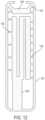
- FIG. 12 is a schematic view of an integrated core-shell mold having a floating tip plenum core 1203.
- the tip plenum core 1203 is held in place relative to the shell with core print filaments 1204, eliminating the need for tip pins as shown in Fig. 9 or a shell lock to attach the tip plenum core to the shell as used in conventional investment casting.
- the core print filaments 1204 exit at or near the top of the tip plenum core 1203.
- the core print filaments 1204 provide additional support holding tip plenum core 1203 in place, and have a cross sectional area that is sufficiently large to support the weight of the tip plenum core during the casting process.
- the cross sectional area of a core print filament is generally larger than the cross sectional area of the cooling hole filaments.
- the cross sectional area of the core print filament is greater than 2mm 2 , and may have an area on the order of a square centimeter.
- the core print filaments 1204 may be necessary if there are no cooling hole filaments between the tip plenum core and the shell, or if the amount or size of the filaments are insufficient to hold the tip plenum core in place during the metal casting step.
- the provision of core print filaments 1204 allow the tip plenum core 1203 to float above and be disconnected from the main core. This eliminates the need for tip pins that result in tip holes connecting the surface of the turbine blade exposed through the tip plenum to the main core cavity of the turbine blade. The elimination of the tip holes is advantageous since it eliminates the post-casting step of brazing tip holes shut.
- This design provides a novel core-shell structure and eliminates conventional structures such as tip pins and/or a shell lock to hole the tip core relative to the shell.
- cooling hole filaments may be provided to connect the tip plenum core to the shell in a sufficient quantity to hold the tip plenum core in place during the metal casting step.
- FIG. 13 provides an alternative design where core filaments exit to the side of the blade tip plenum 1203.
- the core-shell mold may be cured and/or fired depending upon the requirements of the ceramic core photopolymer material.
- Molten metal may be poured into the mold to form a cast object in the shape and having the features provided by the integrated core-shell mold.
- the molten metal is preferably a superalloy metal that formed into a single crystal superalloy turbine blade or stator vane using techniques known to be used with conventional investment casting molds.
Landscapes
- Engineering & Computer Science (AREA)
- Mechanical Engineering (AREA)
- Chemical & Material Sciences (AREA)
- Manufacturing & Machinery (AREA)
- Materials Engineering (AREA)
- Physics & Mathematics (AREA)
- Optics & Photonics (AREA)
- Ceramic Engineering (AREA)
- Molds, Cores, And Manufacturing Methods Thereof (AREA)
- Turbine Rotor Nozzle Sealing (AREA)
- Mold Materials And Core Materials (AREA)
- Casting Devices For Molds (AREA)
Claims (9)
- Ein Verfahren zum Herstellen einer keramischen Gießform, umfassend:(a) Kontaktieren eines ausgehärteten Teils eines Werkstücks mit einem flüssigen keramischen Photopolymer;(b) Bestrahlen eines Teils des flüssigen keramischen Photopolymers neben dem ausgehärteten Teil durch ein Fenster, wobei das Fenster das flüssige keramische Photopolymer berührt;c) Entfernen des Werkstücks aus dem nicht ausgehärteten flüssigen keramischen Photopolymer; und(d) Wiederholen der Schritte a) bis c) bis zur Bildung einer keramischen Gießform, wobei die keramische Gießform einen Kernabschnitt (1000) und einen Schalenabschnitt (1001) mit mindestens einem Hohlraum zwischen dem Kernabschnitt (1000) und dem Schalenabschnitt (1001) umfasst, wobei der mindestens eine Hohlraum geeignet ist, die Form eines Gussteils beim Gießen und Entfernen der keramischen Gießform zu definieren.
- Das Verfahren nach Anspruch 1, wobei das Verfahren nach Schritt (d) einen Schritt (e) umfasst, der das Gießen eines flüssigen Metalls in eine keramische Gießform und das Erstarren des flüssigen Metalls zur Bildung der gegossenen Komponente umfasst.
- Das Verfahren nach Anspruch 2, wobei das Verfahren nach Schritt (e) einen Schritt (f) umfasst, der das Entfernen der keramischen Gießform aus dem Gussteil umfasst.
- Das Verfahren nach einem der Ansprüche 1-3, wobei die keramische Gießform eine Vielzahl von Filamenten (1002) umfasst, die den Kernabschnitt (1000) und den Schalenabschnitt (1001) verbinden, wobei die Filamente (1002) angepasst sind, um nach dem Entfernen der keramischen Gießform eine Vielzahl von Löchern in der Gießkomponente zu definieren, und jedes der mehreren Filamente, die zwischen dem Kernabschnitt (1000) und dem Schalenabschnitt (1001) spannen.
- Das Verfahren nach einem der Ansprüche 1-4, wobei die gegossene Komponente eine Turbinenschaufel oder eine Statorschaufel ist.
- Das Verfahren nach einem der Ansprüche 1-5, wobei die gegossene Komponente eine Turbinenschaufel oder eine Statorschaufel ist und die keramische Gießform eine Vielzahl von Filamenten (1002) umfasst, die den Kernabschnitt (1000) und den Schalenabschnitt (1001) verbinden, wobei sich jedes der mehreren Filamente (1002) zwischen dem Kern und der Schale erstreckt, wobei die Vielzahl von Filamenten (1002) angepasst ist, um eine Vielzahl von Kühllöchern in der Turbinenschaufel oder der Statorschaufel nach Entfernung der keramischen Gießform zu definieren.
- Das Verfahren nach einem der Ansprüche 1-6, wobei die keramische Gießform eine Mehrzahl von Filamenten (1002) umfasst, die den Kernabschnitt (1000) und den Schalenabschnitt (1001) verbinden, wobei sich jede der Mehrzahl von Filamenten (1002) zwischen dem Kernabschnitt (1000) und dem Schalenabschnitt (1001) erstreckt, wobei die Mehrzahl von Filamenten (1002) einen Querschnittsbereich von 0,01 bis 2 mm2 aufweist.
- Das Verfahren zur Herstellung eines Gussteils, das Folgendes umfasst:Bereitstellung einer keramischen Gießform, die nach einem Verfahren nach einem der vorhergehenden Ansprüche hergestellt wurde;Gießen eines flüssigen Metalls (1004) in die keramische Gießform und Erstarren des flüssigen Metalls zur Bildung des Gussteils, wobei die keramische Gießform einen Kernabschnitt (1000) und einen Schalenabschnitt (1001) umfasst, wobei mindestens ein Hohlraum zwischen dem Kernabschnitt (1000) und dem Schalenabschnitt (1001) liegt,der mindestens einen Hohlraum aufweist, der angepasst ist, um die Form des Gussteils beim Gießen und Entfernen der keramischen Gießform zu definieren, und die keramische Gießform ferner eine Vielzahl von Filamenten (1002) aufweist, die den Kernabschnitt (1000) und den Schalenabschnitt (1001) verbinden, wobei jedes der mehreren Filamente (1002) zwischen dem Kernabschnitt (1000) und dem Schalenabschnitt (1001) liegt, wobei jedes der mehreren Filamente (1002) zwischen dem Kernabschnitt (1000) und dem Schalenabschnitt (1001) liegt), die angepasst sind, um eine Vielzahl von Löchern in der Gießkomponente nach Entfernung der keramischen Gießform zu definieren, wobei jedes der mehreren Filamenten (1002) zwischen dem Kernabschnitt (1002) zwischen dem Kernabschnitt und dem Kernabschnitt (1002) einen Querschnitt von0,01 mm aufweist; und Entfernen der keramischen Gussform von der Gusskomponente durch Auswaschen mindestens eines Teils des keramischen Kernabschnitts (1000) durch die Löcher in der Gusskomponente, die von den Filamenten (1002) bereitgestellt werden.
- Das Verfahren nach Anspruch 8, wobei die gegossene Komponente eine Turbinenschaufel oder eine Statorschaufel ist und die Filamente (1002) angepasst sind, um eine Vielzahl von Kühllöchern in der Turbinenschaufel oder der Statorschaufel beim Entfernen der keramischen Gießform zu definieren.
Applications Claiming Priority (2)
| Application Number | Priority Date | Filing Date | Title |
|---|---|---|---|
| US15/377,728 US20180161854A1 (en) | 2016-12-13 | 2016-12-13 | Integrated casting core-shell structure |
| PCT/US2017/058549 WO2018111415A1 (en) | 2016-12-13 | 2017-10-26 | Integrated casting core-shell structure |
Publications (2)
| Publication Number | Publication Date |
|---|---|
| EP3554738A1 EP3554738A1 (de) | 2019-10-23 |
| EP3554738B1 true EP3554738B1 (de) | 2024-11-27 |
Family
ID=60320996
Family Applications (1)
| Application Number | Title | Priority Date | Filing Date |
|---|---|---|---|
| EP17797808.7A Active EP3554738B1 (de) | 2016-12-13 | 2017-10-26 | Verfahren zum herstellen einer integrierten kern-schale-giessstruktur und dessen verwendung |
Country Status (6)
| Country | Link |
|---|---|
| US (1) | US20180161854A1 (de) |
| EP (1) | EP3554738B1 (de) |
| JP (1) | JP7327742B2 (de) |
| CN (1) | CN110072645B (de) |
| CA (1) | CA3045623C (de) |
| WO (1) | WO2018111415A1 (de) |
Families Citing this family (24)
| Publication number | Priority date | Publication date | Assignee | Title |
|---|---|---|---|---|
| US11813669B2 (en) | 2016-12-13 | 2023-11-14 | General Electric Company | Method for making an integrated core-shell structure |
| US20180161852A1 (en) * | 2016-12-13 | 2018-06-14 | General Electric Company | Integrated casting core-shell structure with printed tubes for making cast component |
| US20180161866A1 (en) | 2016-12-13 | 2018-06-14 | General Electric Company | Multi-piece integrated core-shell structure for making cast component |
| US20180161853A1 (en) * | 2016-12-13 | 2018-06-14 | General Electric Company | Integrated casting core-shell structure with floating tip plenum |
| US10807154B2 (en) * | 2016-12-13 | 2020-10-20 | General Electric Company | Integrated casting core-shell structure for making cast component with cooling holes in inaccessible locations |
| US11154956B2 (en) | 2017-02-22 | 2021-10-26 | General Electric Company | Method of repairing turbine component using ultra-thin plate |
| US10625342B2 (en) | 2017-02-22 | 2020-04-21 | General Electric Company | Method of repairing turbine component |
| US10610933B2 (en) | 2017-02-22 | 2020-04-07 | General Electric Company | Method of manufacturing turbine airfoil with open tip casting and tip component thereof |
| US10717130B2 (en) | 2017-02-22 | 2020-07-21 | General Electric Company | Method of manufacturing turbine airfoil and tip component thereof |
| US10702958B2 (en) | 2017-02-22 | 2020-07-07 | General Electric Company | Method of manufacturing turbine airfoil and tip component thereof using ceramic core with witness feature |
| US10391670B2 (en) | 2017-06-28 | 2019-08-27 | General Electric Company | Additively manufactured integrated casting core structure with ceramic shell |
| US10391549B2 (en) | 2017-06-28 | 2019-08-27 | General Electric Company | Additively manufactured casting core-shell hybrid mold and ceramic shell |
| US11173542B2 (en) | 2017-06-28 | 2021-11-16 | General Electric Company | Additively manufactured casting core-shell mold and ceramic shell with variable thermal properties |
| US10974312B2 (en) | 2017-06-28 | 2021-04-13 | General Electric Company | Additively manufactured casting core-shell mold with integrated filter and ceramic shell |
| US11192172B2 (en) | 2017-06-28 | 2021-12-07 | General Electric Company | Additively manufactured interlocking casting core structure with ceramic shell |
| US12168309B2 (en) * | 2021-05-11 | 2024-12-17 | General Electric Company | Methods for casting a component via a unitary core-shell mold |
| US12392290B2 (en) | 2022-11-01 | 2025-08-19 | General Electric Company | Gas turbine engine |
| US12535033B2 (en) | 2022-11-01 | 2026-01-27 | General Electric Company | Gas turbine engine |
| US12503980B2 (en) | 2022-11-01 | 2025-12-23 | General Electric Company | Gas turbine engine |
| US12196131B2 (en) | 2022-11-01 | 2025-01-14 | General Electric Company | Gas turbine engine |
| US12428992B2 (en) | 2022-11-01 | 2025-09-30 | General Electric Company | Gas turbine engine |
| US12410753B2 (en) | 2022-11-01 | 2025-09-09 | General Electric Company | Gas turbine engine |
| CN119839239A (zh) * | 2025-01-13 | 2025-04-18 | 中国航发南方工业有限公司 | 一种基于3d打印陶瓷型芯成形复杂紧凑腔体精密铸件的方法 |
| US12540551B1 (en) | 2025-07-01 | 2026-02-03 | General Electric Company | Gas turbine engines including splittered airfoils |
Family Cites Families (18)
| Publication number | Priority date | Publication date | Assignee | Title |
|---|---|---|---|---|
| US5256340A (en) | 1988-04-18 | 1993-10-26 | 3D Systems, Inc. | Method of making a three-dimensional object by stereolithography |
| US5387380A (en) | 1989-12-08 | 1995-02-07 | Massachusetts Institute Of Technology | Three-dimensional printing techniques |
| CA2351322C (en) * | 1998-11-20 | 2008-07-29 | Rolls-Royce Corporation | Method and apparatus for production of a cast component |
| US6932145B2 (en) | 1998-11-20 | 2005-08-23 | Rolls-Royce Corporation | Method and apparatus for production of a cast component |
| US7172012B1 (en) * | 2004-07-14 | 2007-02-06 | United Technologies Corporation | Investment casting |
| US7306026B2 (en) * | 2005-09-01 | 2007-12-11 | United Technologies Corporation | Cooled turbine airfoils and methods of manufacture |
| US8636496B2 (en) * | 2008-05-05 | 2014-01-28 | Georgia Tech Research Corporation | Systems and methods for fabricating three-dimensional objects |
| WO2010045950A1 (de) | 2008-10-20 | 2010-04-29 | Ivoclar Vivadent Ag | Vorrichtung und verfahren zur verarbeitung von lichtpolymerisierbarem material zum schichtweisen aufbau von formkörpern |
| US20130333855A1 (en) * | 2010-12-07 | 2013-12-19 | Gary B. Merrill | Investment casting utilizing flexible wax pattern tool for supporting a ceramic core along its length during wax injection |
| EP2505341B1 (de) | 2011-03-29 | 2013-05-08 | Ivoclar Vivadent AG | Verfahren zum schichtweisen Aufbau eines Formkörpers aus hochviskosem photopolymerisierbarem Material |
| US9835035B2 (en) | 2013-03-12 | 2017-12-05 | Howmet Corporation | Cast-in cooling features especially for turbine airfoils |
| US9415438B2 (en) * | 2013-04-19 | 2016-08-16 | United Technologies Corporation | Method for forming single crystal parts using additive manufacturing and remelt |
| CN205416365U (zh) * | 2015-09-06 | 2016-08-03 | 朱宗文 | 一种快速提拉成型3d打印系统 |
| CN205736046U (zh) * | 2016-06-20 | 2016-11-30 | 深圳市未来工场科技有限公司 | 一种dlp技术的3d打印机装置 |
| CN205736050U (zh) * | 2016-06-27 | 2016-11-30 | 西安科技大学 | 一种用于制备三维光弹性模型的紫外面曝光快速成型装置 |
| US20180161853A1 (en) * | 2016-12-13 | 2018-06-14 | General Electric Company | Integrated casting core-shell structure with floating tip plenum |
| US20180161856A1 (en) * | 2016-12-13 | 2018-06-14 | General Electric Company | Integrated casting core-shell structure and filter for making cast component |
| US20180161852A1 (en) * | 2016-12-13 | 2018-06-14 | General Electric Company | Integrated casting core-shell structure with printed tubes for making cast component |
-
2016
- 2016-12-13 US US15/377,728 patent/US20180161854A1/en not_active Abandoned
-
2017
- 2017-10-26 CN CN201780076795.6A patent/CN110072645B/zh active Active
- 2017-10-26 JP JP2019531675A patent/JP7327742B2/ja active Active
- 2017-10-26 CA CA3045623A patent/CA3045623C/en active Active
- 2017-10-26 WO PCT/US2017/058549 patent/WO2018111415A1/en not_active Ceased
- 2017-10-26 EP EP17797808.7A patent/EP3554738B1/de active Active
Also Published As
| Publication number | Publication date |
|---|---|
| JP2020515412A (ja) | 2020-05-28 |
| CA3045623A1 (en) | 2018-06-21 |
| EP3554738A1 (de) | 2019-10-23 |
| CA3045623C (en) | 2023-10-03 |
| US20180161854A1 (en) | 2018-06-14 |
| CN110072645A (zh) | 2019-07-30 |
| JP7327742B2 (ja) | 2023-08-16 |
| CN110072645B (zh) | 2022-06-10 |
| WO2018111415A1 (en) | 2018-06-21 |
Similar Documents
| Publication | Publication Date | Title |
|---|---|---|
| EP3554738B1 (de) | Verfahren zum herstellen einer integrierten kern-schale-giessstruktur und dessen verwendung | |
| EP3554748B1 (de) | Integrierte kern-schale-giessstruktur mit schwimmender spitzenkammer | |
| EP3558562B1 (de) | Verfahren zur herstellung einer integrierten kern-schale-gussform zur herstellung eines gussteils mit kühllöchern an unzugänglichen stellen | |
| CA3045612C (en) | Integrated casting core-shell structure with printed tubes for making cast component | |
| CA3045607C (en) | Multi-piece integrated core-shell structure for making cast component | |
| EP3554742B1 (de) | Mehrteilige integrierte kern-schale-gussform mit abstandshalter und/oder stossfänger und verfahren zu deren herstellung | |
| EP4086020B1 (de) | Integrierte kern-schale-giessstruktur zur herstellung eines gussteils mit nichtlinearen öffnungen | |
| EP3532216B1 (de) | Verfahren zur herstellung einer integrierten keramik-kern-schalen-gussform für eine turbinenschaufel oder leitschaufel mit dünnen wurzelkomponenten |
Legal Events
| Date | Code | Title | Description |
|---|---|---|---|
| STAA | Information on the status of an ep patent application or granted ep patent |
Free format text: STATUS: UNKNOWN |
|
| STAA | Information on the status of an ep patent application or granted ep patent |
Free format text: STATUS: THE INTERNATIONAL PUBLICATION HAS BEEN MADE |
|
| PUAI | Public reference made under article 153(3) epc to a published international application that has entered the european phase |
Free format text: ORIGINAL CODE: 0009012 |
|
| STAA | Information on the status of an ep patent application or granted ep patent |
Free format text: STATUS: REQUEST FOR EXAMINATION WAS MADE |
|
| 17P | Request for examination filed |
Effective date: 20190528 |
|
| AK | Designated contracting states |
Kind code of ref document: A1 Designated state(s): AL AT BE BG CH CY CZ DE DK EE ES FI FR GB GR HR HU IE IS IT LI LT LU LV MC MK MT NL NO PL PT RO RS SE SI SK SM TR |
|
| AX | Request for extension of the european patent |
Extension state: BA ME |
|
| RIN1 | Information on inventor provided before grant (corrected) |
Inventor name: YANG, XI Inventor name: MCCARREN, MICHAEL, JOHN Inventor name: KONITZER, DOUGLAS, GERARD Inventor name: DEINES, JAMES, HERBERT Inventor name: PRZESLAWSKI, BRIAN, DAVID Inventor name: MARUSKO, MARK, WILLARD |
|
| DAV | Request for validation of the european patent (deleted) | ||
| DAX | Request for extension of the european patent (deleted) | ||
| STAA | Information on the status of an ep patent application or granted ep patent |
Free format text: STATUS: EXAMINATION IS IN PROGRESS |
|
| 17Q | First examination report despatched |
Effective date: 20221007 |
|
| REG | Reference to a national code |
Ref country code: DE Ref legal event code: R079 Free format text: PREVIOUS MAIN CLASS: B22C0007020000 Ipc: B22C0009100000 Ref country code: DE Ref legal event code: R079 Ref document number: 602017086412 Country of ref document: DE Free format text: PREVIOUS MAIN CLASS: B22C0007020000 Ipc: B22C0009100000 |
|
| GRAP | Despatch of communication of intention to grant a patent |
Free format text: ORIGINAL CODE: EPIDOSNIGR1 |
|
| STAA | Information on the status of an ep patent application or granted ep patent |
Free format text: STATUS: GRANT OF PATENT IS INTENDED |
|
| RIC1 | Information provided on ipc code assigned before grant |
Ipc: B29C 64/129 20170101ALI20240424BHEP Ipc: B28B 7/34 20060101ALI20240424BHEP Ipc: B22C 9/04 20060101ALI20240424BHEP Ipc: B22C 9/10 20060101AFI20240424BHEP |
|
| INTG | Intention to grant announced |
Effective date: 20240521 |
|
| GRAS | Grant fee paid |
Free format text: ORIGINAL CODE: EPIDOSNIGR3 |
|
| P01 | Opt-out of the competence of the unified patent court (upc) registered |
Free format text: CASE NUMBER: APP_52257/2024 Effective date: 20240917 |
|
| GRAA | (expected) grant |
Free format text: ORIGINAL CODE: 0009210 |
|
| STAA | Information on the status of an ep patent application or granted ep patent |
Free format text: STATUS: THE PATENT HAS BEEN GRANTED |
|
| AK | Designated contracting states |
Kind code of ref document: B1 Designated state(s): AL AT BE BG CH CY CZ DE DK EE ES FI FR GB GR HR HU IE IS IT LI LT LU LV MC MK MT NL NO PL PT RO RS SE SI SK SM TR |
|
| REG | Reference to a national code |
Ref country code: GB Ref legal event code: FG4D |
|
| REG | Reference to a national code |
Ref country code: CH Ref legal event code: EP |
|
| REG | Reference to a national code |
Ref country code: DE Ref legal event code: R096 Ref document number: 602017086412 Country of ref document: DE |
|
| REG | Reference to a national code |
Ref country code: IE Ref legal event code: FG4D |
|
| REG | Reference to a national code |
Ref country code: LT Ref legal event code: MG9D |
|
| REG | Reference to a national code |
Ref country code: NL Ref legal event code: MP Effective date: 20241127 |
|
| PG25 | Lapsed in a contracting state [announced via postgrant information from national office to epo] |
Ref country code: PT Free format text: LAPSE BECAUSE OF FAILURE TO SUBMIT A TRANSLATION OF THE DESCRIPTION OR TO PAY THE FEE WITHIN THE PRESCRIBED TIME-LIMIT Effective date: 20250327 Ref country code: IS Free format text: LAPSE BECAUSE OF FAILURE TO SUBMIT A TRANSLATION OF THE DESCRIPTION OR TO PAY THE FEE WITHIN THE PRESCRIBED TIME-LIMIT Effective date: 20250327 Ref country code: HR Free format text: LAPSE BECAUSE OF FAILURE TO SUBMIT A TRANSLATION OF THE DESCRIPTION OR TO PAY THE FEE WITHIN THE PRESCRIBED TIME-LIMIT Effective date: 20241127 |
|
| PG25 | Lapsed in a contracting state [announced via postgrant information from national office to epo] |
Ref country code: FI Free format text: LAPSE BECAUSE OF FAILURE TO SUBMIT A TRANSLATION OF THE DESCRIPTION OR TO PAY THE FEE WITHIN THE PRESCRIBED TIME-LIMIT Effective date: 20241127 Ref country code: NL Free format text: LAPSE BECAUSE OF FAILURE TO SUBMIT A TRANSLATION OF THE DESCRIPTION OR TO PAY THE FEE WITHIN THE PRESCRIBED TIME-LIMIT Effective date: 20241127 |
|
| REG | Reference to a national code |
Ref country code: AT Ref legal event code: MK05 Ref document number: 1745251 Country of ref document: AT Kind code of ref document: T Effective date: 20241127 |
|
| PG25 | Lapsed in a contracting state [announced via postgrant information from national office to epo] |
Ref country code: BG Free format text: LAPSE BECAUSE OF FAILURE TO SUBMIT A TRANSLATION OF THE DESCRIPTION OR TO PAY THE FEE WITHIN THE PRESCRIBED TIME-LIMIT Effective date: 20241127 |
|
| PG25 | Lapsed in a contracting state [announced via postgrant information from national office to epo] |
Ref country code: ES Free format text: LAPSE BECAUSE OF FAILURE TO SUBMIT A TRANSLATION OF THE DESCRIPTION OR TO PAY THE FEE WITHIN THE PRESCRIBED TIME-LIMIT Effective date: 20241127 |
|
| PG25 | Lapsed in a contracting state [announced via postgrant information from national office to epo] |
Ref country code: NO Free format text: LAPSE BECAUSE OF FAILURE TO SUBMIT A TRANSLATION OF THE DESCRIPTION OR TO PAY THE FEE WITHIN THE PRESCRIBED TIME-LIMIT Effective date: 20250227 |
|
| PG25 | Lapsed in a contracting state [announced via postgrant information from national office to epo] |
Ref country code: LV Free format text: LAPSE BECAUSE OF FAILURE TO SUBMIT A TRANSLATION OF THE DESCRIPTION OR TO PAY THE FEE WITHIN THE PRESCRIBED TIME-LIMIT Effective date: 20241127 Ref country code: GR Free format text: LAPSE BECAUSE OF FAILURE TO SUBMIT A TRANSLATION OF THE DESCRIPTION OR TO PAY THE FEE WITHIN THE PRESCRIBED TIME-LIMIT Effective date: 20250228 Ref country code: AT Free format text: LAPSE BECAUSE OF FAILURE TO SUBMIT A TRANSLATION OF THE DESCRIPTION OR TO PAY THE FEE WITHIN THE PRESCRIBED TIME-LIMIT Effective date: 20241127 |
|
| PG25 | Lapsed in a contracting state [announced via postgrant information from national office to epo] |
Ref country code: PL Free format text: LAPSE BECAUSE OF FAILURE TO SUBMIT A TRANSLATION OF THE DESCRIPTION OR TO PAY THE FEE WITHIN THE PRESCRIBED TIME-LIMIT Effective date: 20241127 |
|
| PG25 | Lapsed in a contracting state [announced via postgrant information from national office to epo] |
Ref country code: RS Free format text: LAPSE BECAUSE OF FAILURE TO SUBMIT A TRANSLATION OF THE DESCRIPTION OR TO PAY THE FEE WITHIN THE PRESCRIBED TIME-LIMIT Effective date: 20250227 |
|
| PG25 | Lapsed in a contracting state [announced via postgrant information from national office to epo] |
Ref country code: SM Free format text: LAPSE BECAUSE OF FAILURE TO SUBMIT A TRANSLATION OF THE DESCRIPTION OR TO PAY THE FEE WITHIN THE PRESCRIBED TIME-LIMIT Effective date: 20241127 |
|
| PG25 | Lapsed in a contracting state [announced via postgrant information from national office to epo] |
Ref country code: DK Free format text: LAPSE BECAUSE OF FAILURE TO SUBMIT A TRANSLATION OF THE DESCRIPTION OR TO PAY THE FEE WITHIN THE PRESCRIBED TIME-LIMIT Effective date: 20241127 |
|
| PG25 | Lapsed in a contracting state [announced via postgrant information from national office to epo] |
Ref country code: EE Free format text: LAPSE BECAUSE OF FAILURE TO SUBMIT A TRANSLATION OF THE DESCRIPTION OR TO PAY THE FEE WITHIN THE PRESCRIBED TIME-LIMIT Effective date: 20241127 |
|
| PG25 | Lapsed in a contracting state [announced via postgrant information from national office to epo] |
Ref country code: RO Free format text: LAPSE BECAUSE OF FAILURE TO SUBMIT A TRANSLATION OF THE DESCRIPTION OR TO PAY THE FEE WITHIN THE PRESCRIBED TIME-LIMIT Effective date: 20241127 |
|
| PG25 | Lapsed in a contracting state [announced via postgrant information from national office to epo] |
Ref country code: SK Free format text: LAPSE BECAUSE OF FAILURE TO SUBMIT A TRANSLATION OF THE DESCRIPTION OR TO PAY THE FEE WITHIN THE PRESCRIBED TIME-LIMIT Effective date: 20241127 |
|
| PG25 | Lapsed in a contracting state [announced via postgrant information from national office to epo] |
Ref country code: CZ Free format text: LAPSE BECAUSE OF FAILURE TO SUBMIT A TRANSLATION OF THE DESCRIPTION OR TO PAY THE FEE WITHIN THE PRESCRIBED TIME-LIMIT Effective date: 20241127 |
|
| PG25 | Lapsed in a contracting state [announced via postgrant information from national office to epo] |
Ref country code: IT Free format text: LAPSE BECAUSE OF FAILURE TO SUBMIT A TRANSLATION OF THE DESCRIPTION OR TO PAY THE FEE WITHIN THE PRESCRIBED TIME-LIMIT Effective date: 20241127 |
|
| REG | Reference to a national code |
Ref country code: DE Ref legal event code: R097 Ref document number: 602017086412 Country of ref document: DE |
|
| PG25 | Lapsed in a contracting state [announced via postgrant information from national office to epo] |
Ref country code: SE Free format text: LAPSE BECAUSE OF FAILURE TO SUBMIT A TRANSLATION OF THE DESCRIPTION OR TO PAY THE FEE WITHIN THE PRESCRIBED TIME-LIMIT Effective date: 20241127 |
|
| PLBE | No opposition filed within time limit |
Free format text: ORIGINAL CODE: 0009261 |
|
| STAA | Information on the status of an ep patent application or granted ep patent |
Free format text: STATUS: NO OPPOSITION FILED WITHIN TIME LIMIT |
|
| PGFP | Annual fee paid to national office [announced via postgrant information from national office to epo] |
Ref country code: GB Payment date: 20250923 Year of fee payment: 9 |
|
| PGFP | Annual fee paid to national office [announced via postgrant information from national office to epo] |
Ref country code: FR Payment date: 20250923 Year of fee payment: 9 |
|
| 26N | No opposition filed |
Effective date: 20250828 |
|
| PGFP | Annual fee paid to national office [announced via postgrant information from national office to epo] |
Ref country code: DE Payment date: 20250923 Year of fee payment: 9 |