EP3554614B1 - Medical balloons, balloon catheters, and methods thereof - Google Patents
Medical balloons, balloon catheters, and methods thereof Download PDFInfo
- Publication number
- EP3554614B1 EP3554614B1 EP17881095.8A EP17881095A EP3554614B1 EP 3554614 B1 EP3554614 B1 EP 3554614B1 EP 17881095 A EP17881095 A EP 17881095A EP 3554614 B1 EP3554614 B1 EP 3554614B1
- Authority
- EP
- European Patent Office
- Prior art keywords
- balloon
- composite
- fiber tube
- expanded
- fiber
- Prior art date
- Legal status (The legal status is an assumption and is not a legal conclusion. Google has not performed a legal analysis and makes no representation as to the accuracy of the status listed.)
- Active
Links
Images


Classifications
-
- A—HUMAN NECESSITIES
- A61—MEDICAL OR VETERINARY SCIENCE; HYGIENE
- A61L—METHODS OR APPARATUS FOR STERILISING MATERIALS OR OBJECTS IN GENERAL; DISINFECTION, STERILISATION OR DEODORISATION OF AIR; CHEMICAL ASPECTS OF BANDAGES, DRESSINGS, ABSORBENT PADS OR SURGICAL ARTICLES; MATERIALS FOR BANDAGES, DRESSINGS, ABSORBENT PADS OR SURGICAL ARTICLES
- A61L29/00—Materials for catheters, medical tubing, cannulae, or endoscopes or for coating catheters
- A61L29/04—Macromolecular materials
- A61L29/041—Macromolecular materials obtained by reactions only involving carbon-to-carbon unsaturated bonds
-
- A—HUMAN NECESSITIES
- A61—MEDICAL OR VETERINARY SCIENCE; HYGIENE
- A61L—METHODS OR APPARATUS FOR STERILISING MATERIALS OR OBJECTS IN GENERAL; DISINFECTION, STERILISATION OR DEODORISATION OF AIR; CHEMICAL ASPECTS OF BANDAGES, DRESSINGS, ABSORBENT PADS OR SURGICAL ARTICLES; MATERIALS FOR BANDAGES, DRESSINGS, ABSORBENT PADS OR SURGICAL ARTICLES
- A61L29/00—Materials for catheters, medical tubing, cannulae, or endoscopes or for coating catheters
- A61L29/04—Macromolecular materials
- A61L29/06—Macromolecular materials obtained otherwise than by reactions only involving carbon-to-carbon unsaturated bonds
-
- A—HUMAN NECESSITIES
- A61—MEDICAL OR VETERINARY SCIENCE; HYGIENE
- A61L—METHODS OR APPARATUS FOR STERILISING MATERIALS OR OBJECTS IN GENERAL; DISINFECTION, STERILISATION OR DEODORISATION OF AIR; CHEMICAL ASPECTS OF BANDAGES, DRESSINGS, ABSORBENT PADS OR SURGICAL ARTICLES; MATERIALS FOR BANDAGES, DRESSINGS, ABSORBENT PADS OR SURGICAL ARTICLES
- A61L29/00—Materials for catheters, medical tubing, cannulae, or endoscopes or for coating catheters
- A61L29/12—Composite materials, i.e. containing one material dispersed in a matrix of the same or different material
- A61L29/126—Composite materials, i.e. containing one material dispersed in a matrix of the same or different material having a macromolecular matrix
-
- A—HUMAN NECESSITIES
- A61—MEDICAL OR VETERINARY SCIENCE; HYGIENE
- A61L—METHODS OR APPARATUS FOR STERILISING MATERIALS OR OBJECTS IN GENERAL; DISINFECTION, STERILISATION OR DEODORISATION OF AIR; CHEMICAL ASPECTS OF BANDAGES, DRESSINGS, ABSORBENT PADS OR SURGICAL ARTICLES; MATERIALS FOR BANDAGES, DRESSINGS, ABSORBENT PADS OR SURGICAL ARTICLES
- A61L29/00—Materials for catheters, medical tubing, cannulae, or endoscopes or for coating catheters
- A61L29/14—Materials characterised by their function or physical properties, e.g. lubricating compositions
- A61L29/143—Stabilizers
-
- A—HUMAN NECESSITIES
- A61—MEDICAL OR VETERINARY SCIENCE; HYGIENE
- A61M—DEVICES FOR INTRODUCING MEDIA INTO, OR ONTO, THE BODY; DEVICES FOR TRANSDUCING BODY MEDIA OR FOR TAKING MEDIA FROM THE BODY; DEVICES FOR PRODUCING OR ENDING SLEEP OR STUPOR
- A61M25/00—Catheters; Hollow probes
- A61M25/0043—Catheters; Hollow probes characterised by structural features
- A61M25/005—Catheters; Hollow probes characterised by structural features with embedded materials for reinforcement, e.g. wires, coils, braids
- A61M25/0052—Localized reinforcement, e.g. where only a specific part of the catheter is reinforced, for rapid exchange guidewire port
-
- A—HUMAN NECESSITIES
- A61—MEDICAL OR VETERINARY SCIENCE; HYGIENE
- A61M—DEVICES FOR INTRODUCING MEDIA INTO, OR ONTO, THE BODY; DEVICES FOR TRANSDUCING BODY MEDIA OR FOR TAKING MEDIA FROM THE BODY; DEVICES FOR PRODUCING OR ENDING SLEEP OR STUPOR
- A61M25/00—Catheters; Hollow probes
- A61M25/0043—Catheters; Hollow probes characterised by structural features
- A61M25/0054—Catheters; Hollow probes characterised by structural features with regions for increasing flexibility
-
- A—HUMAN NECESSITIES
- A61—MEDICAL OR VETERINARY SCIENCE; HYGIENE
- A61M—DEVICES FOR INTRODUCING MEDIA INTO, OR ONTO, THE BODY; DEVICES FOR TRANSDUCING BODY MEDIA OR FOR TAKING MEDIA FROM THE BODY; DEVICES FOR PRODUCING OR ENDING SLEEP OR STUPOR
- A61M25/00—Catheters; Hollow probes
- A61M25/10—Balloon catheters
- A61M25/1018—Balloon inflating or inflation-control devices
- A61M25/10181—Means for forcing inflation fluid into the balloon
-
- A—HUMAN NECESSITIES
- A61—MEDICAL OR VETERINARY SCIENCE; HYGIENE
- A61M—DEVICES FOR INTRODUCING MEDIA INTO, OR ONTO, THE BODY; DEVICES FOR TRANSDUCING BODY MEDIA OR FOR TAKING MEDIA FROM THE BODY; DEVICES FOR PRODUCING OR ENDING SLEEP OR STUPOR
- A61M25/00—Catheters; Hollow probes
- A61M25/10—Balloon catheters
- A61M25/1027—Making of balloon catheters
- A61M25/1029—Production methods of the balloon members, e.g. blow-moulding, extruding, deposition or by wrapping a plurality of layers of balloon material around a mandril
-
- A—HUMAN NECESSITIES
- A61—MEDICAL OR VETERINARY SCIENCE; HYGIENE
- A61M—DEVICES FOR INTRODUCING MEDIA INTO, OR ONTO, THE BODY; DEVICES FOR TRANSDUCING BODY MEDIA OR FOR TAKING MEDIA FROM THE BODY; DEVICES FOR PRODUCING OR ENDING SLEEP OR STUPOR
- A61M25/00—Catheters; Hollow probes
- A61M25/10—Balloon catheters
- A61M25/1027—Making of balloon catheters
- A61M25/1034—Joining of shaft and balloon
-
- A—HUMAN NECESSITIES
- A61—MEDICAL OR VETERINARY SCIENCE; HYGIENE
- A61M—DEVICES FOR INTRODUCING MEDIA INTO, OR ONTO, THE BODY; DEVICES FOR TRANSDUCING BODY MEDIA OR FOR TAKING MEDIA FROM THE BODY; DEVICES FOR PRODUCING OR ENDING SLEEP OR STUPOR
- A61M25/00—Catheters; Hollow probes
- A61M25/10—Balloon catheters
- A61M25/104—Balloon catheters used for angioplasty
-
- A—HUMAN NECESSITIES
- A61—MEDICAL OR VETERINARY SCIENCE; HYGIENE
- A61M—DEVICES FOR INTRODUCING MEDIA INTO, OR ONTO, THE BODY; DEVICES FOR TRANSDUCING BODY MEDIA OR FOR TAKING MEDIA FROM THE BODY; DEVICES FOR PRODUCING OR ENDING SLEEP OR STUPOR
- A61M25/00—Catheters; Hollow probes
- A61M25/10—Balloon catheters
- A61M25/1027—Making of balloon catheters
- A61M25/1029—Production methods of the balloon members, e.g. blow-moulding, extruding, deposition or by wrapping a plurality of layers of balloon material around a mandril
- A61M2025/1031—Surface processing of balloon members, e.g. coating or deposition; Mounting additional parts onto the balloon member's surface
-
- A—HUMAN NECESSITIES
- A61—MEDICAL OR VETERINARY SCIENCE; HYGIENE
- A61M—DEVICES FOR INTRODUCING MEDIA INTO, OR ONTO, THE BODY; DEVICES FOR TRANSDUCING BODY MEDIA OR FOR TAKING MEDIA FROM THE BODY; DEVICES FOR PRODUCING OR ENDING SLEEP OR STUPOR
- A61M25/00—Catheters; Hollow probes
- A61M25/10—Balloon catheters
- A61M2025/1043—Balloon catheters with special features or adapted for special applications
- A61M2025/1075—Balloon catheters with special features or adapted for special applications having a balloon composed of several layers, e.g. by coating or embedding
-
- A—HUMAN NECESSITIES
- A61—MEDICAL OR VETERINARY SCIENCE; HYGIENE
- A61M—DEVICES FOR INTRODUCING MEDIA INTO, OR ONTO, THE BODY; DEVICES FOR TRANSDUCING BODY MEDIA OR FOR TAKING MEDIA FROM THE BODY; DEVICES FOR PRODUCING OR ENDING SLEEP OR STUPOR
- A61M25/00—Catheters; Hollow probes
- A61M25/10—Balloon catheters
- A61M2025/1043—Balloon catheters with special features or adapted for special applications
- A61M2025/1084—Balloon catheters with special features or adapted for special applications having features for increasing the shape stability, the reproducibility or for limiting expansion, e.g. containments, wrapped around fibres, yarns or strands
-
- A—HUMAN NECESSITIES
- A61—MEDICAL OR VETERINARY SCIENCE; HYGIENE
- A61M—DEVICES FOR INTRODUCING MEDIA INTO, OR ONTO, THE BODY; DEVICES FOR TRANSDUCING BODY MEDIA OR FOR TAKING MEDIA FROM THE BODY; DEVICES FOR PRODUCING OR ENDING SLEEP OR STUPOR
- A61M25/00—Catheters; Hollow probes
- A61M25/10—Balloon catheters
- A61M2025/1043—Balloon catheters with special features or adapted for special applications
- A61M2025/1086—Balloon catheters with special features or adapted for special applications having a special balloon surface topography, e.g. pores, protuberances, spikes or grooves
-
- A—HUMAN NECESSITIES
- A61—MEDICAL OR VETERINARY SCIENCE; HYGIENE
- A61M—DEVICES FOR INTRODUCING MEDIA INTO, OR ONTO, THE BODY; DEVICES FOR TRANSDUCING BODY MEDIA OR FOR TAKING MEDIA FROM THE BODY; DEVICES FOR PRODUCING OR ENDING SLEEP OR STUPOR
- A61M25/00—Catheters; Hollow probes
- A61M25/10—Balloon catheters
- A61M2025/1043—Balloon catheters with special features or adapted for special applications
- A61M2025/109—Balloon catheters with special features or adapted for special applications having balloons for removing solid matters, e.g. by grasping or scraping plaque, thrombus or other matters that obstruct the flow
Definitions
- This application generally relates to medical balloons, balloon catheters, and methods thereof.
- Atherosclerosis is characterized by one or more intravascular lesions formed in part of plaque including blood-borne substances such as fat, cholesterol, and calcium.
- An intravascular lesion such as an arterial lesion can form on a wall of an arterial lumen and build out across the lumen to an opposite wall thereof. A last point of patency often occurs at a boundary between the arterial lesion and the opposite wall of the arterial lumen.
- Surgical procedures for atherosclerosis such as balloon angioplasty can be used to restore patency and blood flow lost to the one or more intravascular lesions.
- angioplasty balloons having a low degree of compliance, thin walls, puncture resistance, and improved trackability. Provided herein in some embodiments are systems and methods that address the foregoing.
- US 2008/0183132 A1 discloses a non-compliant medical balloon comprising a base balloon including a pair of spaced apart, generally conical end sections and a generally cylindrical center section connected therebetween.
- US 2007/0250101 A1 discloses a composite fiber reinforced balloon for medical devices.
- US 2012/0330232 A1 discloses a balloon cover provided to enhance the performance of a medical balloon, the cover having overlapping portions and opposed apertures located in apexes of tapered ends of the balloon cover.
- US 2009/0038752 A1 discloses an inflatable balloon for a medical catheter including a base layer or non-compliant balloon substrate, a reinforcing layer, an adhesive, layer adhering the reinforcing layer to the non-compliant balloon substrate and a top coat layer.
- US 2006/0079836 A1 relates to the field of intravascular medical devices, and more specifically to the field of balloon catheters and other similar diagnostic or therapeutic devices for insertion or implantation within the body for treatment or diagnosis of diseases.
- the present invention is directed to the apparatus of claim 1 and the method of claim 10.
- the dependent claims refer to preferred embodiments.
- an apparatus including a composite balloon with a tubular fiber layer and a polymeric balloon layer over the fiber layer.
- the composite balloon can be configured to apply a pressure to surrounding walls of an anatomical vessel in an inflated state of the composite balloon to modify one or more intravascular lesions in the anatomical vessel.
- an apparatus including an elongate catheter body; an inflation lumen disposed within the catheter body; and a composite balloon.
- the elongate catheter body can include a distal portion and a proximal portion, and the composite balloon can be about the distal portion.
- the composite balloon can include a tubularly braided fiber layer and a polymeric balloon layer over the fiber layer.
- the composite balloon can be configured to apply a pressure to surrounding walls of an anatomical vessel in an inflated state of the composite balloon to modify one or more intravascular lesions in the anatomical vessel.
- a method including inserting a collapsed fiber tube into an expanded polymeric balloon; expanding the collapsed fiber tube to provide an expanded fiber tube; and securing the expanded fiber tube to the expanded polymeric balloon.
- the expanded fiber tube can include an outer surface
- the expanded polymeric balloon can include an inner surface.
- Securing the expanded fiber tube to the expanded polymeric balloon can include securing the outer surface of the expanded fiber tube to the inner surface of the expanded polymeric balloon.
- the method can include forming a composite balloon configured to apply a pressure to surrounding walls of an anatomical vessel in an inflated state of the composite balloon to modify one or more intravascular lesions in the anatomical vessel.
- any labels such as “left,” “right,” “front,” “back,” “top,” “bottom,” “forward,” “reverse,” “clockwise,” “counter clockwise,” “up,” “down,” or other similar terms such as “upper,” “lower,” “aft,” “fore,” “vertical,” “horizontal,” “proximal,” “distal,” and the like are used for convenience and are not intended to imply, for example, any particular fixed location, orientation, or direction. Instead, such labels are used to reflect, for example, relative location, orientation, or directions. It should also be understood that the singular forms of “a,” “an,” and “the” include plural references unless the context clearly dictates otherwise.
- Non-compliance or a low degree of compliance refers to a capability of a medical balloon to substantially maintain a predetermined size and profile under pressure without expanding beyond the predetermined size and profile.
- a non-compliant medical balloon is less likely to rupture or dissect an anatomical vessel as the medical balloon expands.
- Trackability refers to a capability of a medical balloon to traverse a tortuous path through anatomical vessels, body cavities, occlusions, or a combination thereof. Flexible medical balloons generally provide better trackability. A high degree of trackability is desirable.
- Atherosclerosis is characterized by one or more intravascular lesions formed in part of plaque including blood-borne substances such as fat, cholesterol, and calcium.
- An intravascular lesion such as an arterial lesion can form on a wall of an arterial lumen and build out across the lumen to an opposite wall thereof. A last point of patency often occurs at a boundary between the arterial lesion and the opposite wall of the arterial lumen.
- Surgical procedures for atherosclerosis such as balloon angioplasty can be used to restore patency and blood flow lost to the one or more intravascular lesions.
- angioplasty balloons having a low degree of compliance, thin walls, puncture resistance, and improved trackability. Provided herein in some embodiments are systems and methods that address the foregoing.
- an apparatus including a composite balloon with a tubular fiber layer and a polymeric balloon layer over the fiber layer.
- the composite balloon can be configured to apply a pressure to surrounding walls of an anatomical vessel in an inflated state of the composite balloon to modify one or more intravascular lesions in the anatomical vessel.
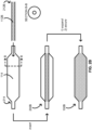
- FIG. 1A provides a schematic illustrating a composite balloon 100 such as a composite balloon 100A in accordance with some embodiments.
- the composite balloon 100A can include a tubular fiber layer 112A and a polymeric balloon layer 114 over the fiber layer 112A.
- the composite balloon 100A can include a cylindrical section 122, conical sections 124a and 124b, and neck sections 126a and 126b.
- the conical section 124a is a distal conical section 124a
- the conical section 124b is a proximal conical section 124b.
- the neck section 126a is a distal neck section 126a
- the neck section 126b is a proximal neck section 126b.
- the conical sections 124a and 124b can be joined to the cylindrical section 122 through shoulders 123a and 123b, wherein the shoulder 123a is a distal shoulder 123a joining the distal conical section 124a to the cylindrical section 122, and wherein the shoulder 123b is a proximal shoulder 123b joining the proximal conical section 124b to the cylindrical section 122.
- the neck sections 126a and 126b can be joined to the conical sections 124a and 124b though junctions 125a and 125b, wherein the junction 125a is a distal junction 125a joining the distal neck section 126a to the distal conical section 124a, and wherein the junction 125b is a proximal junction 125b joining the proximal neck section 126b to the proximal conical section 124b.
- the composite balloon 100A is described in terms of distal portions (e.g., distal conical section 124a, distal neck section 126a, distal shoulder 123a, and distal junctions 125a) and proximal portions (e.g., proximal conical section 124b, proximal neck section 126b, proximal shoulder 123b, and proximal junction 125b), this is merely for convenience as the composite balloon 100A can be symmetric.
- a symmetric balloon such as the composite balloon 100A can be installed on a catheter body such as a catheter body 332 (see FIG. 3A ) in any suitable orientation.
- FIG. 1B provides a schematic illustrating a composite balloon 100 such as a composite balloon 100B in accordance with some embodiments.
- the composite balloon 100B can include many of the same features as the composite balloon 100A shown and described in reference to at least FIG. 1A ; however, the composite balloon 100B differs from the composite balloon 100A in that a fiber layer 112B of the composite balloon 100B extends along the cylindrical section 122 past at least the shoulders 123a and 123b and into the conical sections 124a and 124b.
- the fiber layer 112B extending past at least the shoulders 123a and 123b can include, without limitation, extension of the fiber layer 112B into the conical sections 124a and 124b such as up to and including the junctions 125a and 125b.
- the fiber layer 112A or 112B can be one layer of a fiber tube 212A (see FIG. 2A ) including at least the one fiber layer 112A or 112B.
- the fiber layer 112A or 112B can be ultra high-weight polyethylene, aramid, or a combination thereof.
- the fiber layer 112A or 112B can be tubularly braided or knitted with a continuous wall defining a lumen therethrough.
- a tubularly braided fiber layer 112A or 112B can include three or more intertwined fibers in which no two fibers are exclusively intertwined around each other.
- the fibers in the tubularly braided fiber layer 112A or 112B can be mechanically interlocked with each other providing unique load-distributing properties.
- a tubularly knitted fiber layer 112A or 112B can include intertwined fibers in a series of interconnected loops.
- the fibers in the tubularly knitted fiber layer 112A or 112B can also be mechanically interlocked with each other providing unique load-distributing properties.
- the tubular fiber layer 112A or 112B can be continuous and mechanically locked, the tubular fiber layer 112A or 112B can be configured with a natural mechanism to evenly distribute a load throughout the tubular fiber layer 112A or 112B.
- the balloon layer 114 can be one layer of a balloon 214 (see FIG. 2A ) including at least the one balloon layer 114.
- the balloon layer 114 can be polyurethane, polyethylene, polyethylene terephthalate, polyether block amide, nylon, or a combination thereof.
- the fiber tube 212A or the fiber layer 112A or 112B thereof can be secured to the balloon 214 or the balloon layer 114 thereof in the composite balloon 100A or 100B.
- the fiber tube or the fiber layer 112A or 112B thereof can include an outer surface, and the balloon 214 or the balloon layer 114 thereof can include an inner surface, which surfaces can interface and be secured to each other in the composite balloon 100A or 100B.
- An adhesive such as polyurethane or a solvent weld can be used to secure the outer surface of the fiber tube 212A or the fiber layer 112A or 112B thereof to the inner surface of the balloon 214 or the balloon layer 114 thereof.
- the composite balloon 100B can include a stronger bonding means in the conical sections 124a and 124b and adjacent thereto (e.g., the shoulders 123a and 123b, the junctions 125a and 125b, etc.) than in the cylindrical section 122.
- the stronger bonding means can include a higher-strength adhesive, a deeper solvent weld, or a combination thereof to obviate bond failure that might otherwise occur with a weaker bonding means.
- the composite balloon 100A or 100B can be configured to withstand an inflation pressure of at least 1.01*10 6 Pa (10 atm), including at least 2.03*10 6 Pa (20 atm), such as at least 3.04*10 6 Pa (30 atm), for example, at least 4.05*10 6 Pa (40 atm) or 5.07*10 6 Pa (50 atm).
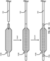
- FIG. 2A provides a schematic illustrating a method for producing a composite balloon such as the composite balloon 100A in accordance with some embodiments.
- the method can include inserting a collapsed fiber tube such as a fiber tube 212A into an expanded polymeric balloon such as a polymeric balloon 214 to provide a nested intermediate 200A.
- the fiber tube 212A can include the fiber layer 112A, and the polymeric balloon 214 can include the balloon layer 114, each of which layers are shown and described in reference to at least FIG. 1A .
- the collapsed fiber tube 212A of the nested intermediate 200A can be expanded to provide an expanded fiber tube 212A in the nested intermediate 200A.
- the collapsed fiber tube 212A can be expanded by pushing on at least one end (e.g., a proximal or distal end) of the collapsed fiber tube 212A toward a middle of the collapsed fiber tube 212A while the other end (e.g., the distal or proximal end) of the collapsed fiber tube 212A is secured or otherwise held in place.
- the collapsed fiber tube 212A can be expanded by pushing on both ends (e.g., the proximal and distal ends) of the collapsed fiber tube 212A toward a middle of the collapsed fiber tube 212A.
- the expanded fiber tube 212A can be subsequently secured to the expanded polymeric balloon 214 to provide the composite balloon 100A.
- the expanded fiber tube 212A can include an outer surface, and the expanded polymeric balloon 214 can include an inner surface, which surfaces can interface in the nested intermediate 200.
- Securing the expanded fiber tube 212A to the expanded polymeric balloon 214 can include securing the outer surface of the expanded fiber tube 212A to the inner surface of the expanded polymeric balloon 214 by applying an adhesive or solvent welding the outer surface of the expanded fiber tube 212A to the inner surface of the expanded polymeric balloon 214.
- FIG. 2B provides a schematic illustrating a method for producing a composite balloon such as the composite balloon 100B in accordance with some embodiments.
- the method for producing the composite balloon 100B can include many of the same features as the method for producing the composite balloon 100A shown and described in reference to at least FIG. 2A ; however, the method for producing the composite balloon 100B differs from the method for producing the composite balloon 100A in that a collapsed fiber tube 212B including the fiber layer 112B is inserted into the expanded polymeric balloon 214 to provide a nested intermediate 200B. As shown and described in reference to at least FIG. 1B , the fiber layer 112B of the fiber tube 212B can extend along the cylindrical section 122 past at least the shoulders 123a and 123b.
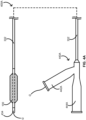
- FIG. 3A provides a schematic illustrating a method for producing a catheter with a composite balloon such as the composite balloon 100A in accordance with some embodiments.
- the method can include inserting an elongate catheter body 332 through a center (e.g., a center along a central axis) of a composite balloon such as the composite balloon 100A to provide a nested intermediate including the composite balloon 100A and the catheter body 332.
- the composite balloon 100A can be symmetric. Accordingly, the composite balloon 100A can be installed on the catheter body 332 in any suitable orientation.
- the neck sections 126a and 126b of the composite balloon 100A can be subsequently secured to a distal portion of the catheter body 332 respectively at secured sections 129a and 129b to provide at least a portion of a catheter such as an over-the-wire catheter (see FIG. 4A ), a rapid-exchange catheter (see FIG. 4B ), or a short rapid-exchange catheter (see FIG. 4C ).
- FIG. 3B provides a schematic illustrating a method for producing a catheter with a composite balloon such as the composite balloon 100B in accordance with some embodiments.
- the method for producing the catheter with the composite balloon 100B can include many of the same features as the method for producing the catheter with the composite balloon 100A shown and described in reference to at least FIG. 3A ; however, the method for producing the catheter with the composite balloon 100B differs from the method for producing the catheter with the composite balloon 100A in the composite balloon 200B itself.
- FIG. 4A provides a schematic illustrating an over-the-wire balloon catheter 400A including the composite balloon 100 in accordance with some embodiments.
- the over-the-wire balloon catheter 400A can include the catheter body 332, the composite balloon 100 such as the composite balloon 100A or the composite balloon 100B (shown) over at least some of a distal portion of the catheter body 332.
- the over-the-wire balloon catheter 400A can further include a tip 434 of a distal end of the catheter body 332 or coupled thereto and a hub 440A at a proximal end of the catheter body 332.
- the over-the-wire balloon catheter 400A can be configured with a guidewire G as shown entering the over-the-wire balloon catheter 400A through a guidewire port 442A in the hub 440A of the over-the-wire balloon catheter 400A.
- the hub 440A can also include an inflation port 444A for attaching an inflation device for controlled inflation and deflation of the composite balloon 100 through a fluidly connected inflation lumen disposed within the catheter body 332.
- FIG. 4B provides a schematic illustrating a rapid-exchange balloon catheter 400B including the composite balloon 100 in accordance with some embodiments.
- the rapid-exchange balloon catheter 400B can include the catheter body 332, the composite balloon 100 such as the composite balloon 100A or the composite balloon 100B (shown) over at least some of the distal portion of the catheter body 332.
- the rapid-exchange balloon catheter 400B can further include the tip 434 at the distal end of the catheter body 332 or coupled thereto.
- the rapid-exchange balloon catheter 400B can further include a hub 440B with an inflation port 444B at the proximal end of the catheter body 332 for attaching an inflation device for controlled inflation and deflation of the composite balloon 100 through a fluidly connected inflation lumen disposed within the catheter body 332.
- the rapid-exchange balloon catheter 400B can be configured with a guidewire G as shown entering the rapid-exchange balloon catheter 400B through a guidewire port 442B of the rapid-exchange balloon catheter 400B.
- the guidewire port 442B can be in a medial portion of the catheter body 332 between the composite balloon 100 and the hub 440B.
- FIG. 4C provides a schematic illustrating a short rapid-exchange balloon catheter 400C including the composite balloon 100 in accordance with some embodiments.
- the rapid-exchange balloon catheter 400C can include the catheter body 332, the composite balloon 100 such as the composite balloon 100A or the composite balloon 100B (shown) over at least some of the distal portion of the catheter body 332.
- the short rapid-exchange balloon catheter 400C can further include the tip 434 at the distal end of the catheter body 332 or coupled thereto.
- the short rapid-exchange balloon catheter 400C can further include the hub 440B with the inflation port 444B at the proximal end of the catheter body 332 for attaching an inflation device for controlled inflation and deflation of the composite balloon 100 through a fluidly connected inflation lumen disposed within the catheter body 332.
- the short rapid-exchange balloon catheter 400C can be configured with a guidewire G as shown entering the short rapid-exchange balloon catheter 400C through a guidewire port 442C of the short rapid-exchange balloon catheter 400C.
- the guidewire port 442C can be in a distal portion of the catheter body 332 between the tip 434 and the composite balloon 100 or in the tip 434 itself.
- Each balloon catheter of the over-the-wire balloon catheter 400A, the rapid-exchange balloon catheter 400B, and the short rapid-exchange balloon catheter 400C can be used in a system with an inflation device configured to inflate the composite balloon 100 for modification of one or more intravascular lesions.
- an inflation device can include a piston pump, a manometer, high-pressure tubing configured to tolerate pressures of at least 3.04*10 6 Pa (30 atm) or 4.05*10 6 Pa (40 atm), and an adapter configured to connect with the hub (e.g., the hub 440A or the hub 440B) at the proximal end of the elongate body 332.
- the inflation device is a CALIBERR Inflation Device or the PRESTOR Inflation Device by Bard Peripheral Vascular, Inc. of Tempe, Arizona.
- FIG. 5 provides a schematic illustrating modification of an intravascular lesion in accordance with some embodiments.
- a balloon catheter such as the over-the-wire balloon catheter 400A, the rapid-exchange balloon catheter 400B, or the short rapid-exchange balloon catheters 400C can be advanced through a patient's vasculature until the composite balloon 100 is in a position alongside an intravascular lesion L. Inflation of the composite balloon 100 in such a position can provide an outwardly focused force against the lesion L along a length of the composite balloon 100, thereby restoring patency lost to the intravascular L.
- the outwardly focused force can increase from a minimum when the composite balloon 100 is in an uninflated or minimally inflated state to a maximum when the composite balloon 100 is in a fully inflated state.
- the foregoing can be effected in vasculature of various sizes and tortuosities.
- the composite balloon 100 can be sufficiently flexible to modify intravascular lesions in curved vasculature.
- a balloon catheter such as the over-the-wire balloon catheter 400A, the blockxchange balloon catheter 400B, or the short rapid-exchange balloon catheters 400C can be used to dilate stenoses in the iliac, femoral, ilio-femoral, popliteal, infra-popliteal, and renal arteries and to treat obstructive lesions of native or synthetic arteriovenous dialysis fistulae.
- the balloon catheter can also be used for post dilatation of balloon-expandable stents, self-expanding stents, and stent grafts in the peripheral vasculature.
- an apparatus including a composite balloon with a tubular fiber layer and a polymeric balloon layer over the fiber layer.
- the composite balloon can be configured to apply a pressure to surrounding walls of an anatomical vessel in an inflated state of the composite balloon to modify one or more intravascular lesions in the anatomical vessel.
- the fiber layer can be ultra high-weight polyethylene, aramid, or a combination thereof, and the fiber layer can be tubularly braided or knitted.
- the balloon layer can be polyurethane, polyethylene, polyethylene terephthalate, polyether block amide, nylon, or a combination thereof.
- the composite balloon can further include an adhesive or a solvent weld bonding the balloon layer to the fiber layer.
- the composite balloon can further include a cylindrical section, conical sections, and shoulders between the cylindrical section and the conical sections, wherein the fiber layer can extend along the cylindrical section past at least the shoulders and into the conical sections.
- the composite balloon can be configured to withstand an inflation pressure of at least 2.03*10 6 Pa (20 atm). In such embodiments, the composite balloon can be configured to provide an outwardly focused force along a length of the composite balloon when the composite balloon is in the inflated state. In such embodiments, the composite balloon can be sufficiently flexible to modify one or more intravascular lesions in curved vasculature when the composite balloon is in the inflated state.
- an apparatus including an elongate catheter body; an inflation lumen disposed within the catheter body; and a composite balloon.
- the elongate catheter body can include a distal portion and a proximal portion, and the composite balloon can be about the distal portion.
- the composite balloon can include a tubularly braided fiber layer and a polymeric balloon layer over the fiber layer.
- the composite balloon can be configured to apply a pressure to surrounding walls of an anatomical vessel in an inflated state of the composite balloon to modify one or more intravascular lesions in the anatomical vessel.
- the fiber layer can be ultra high-weight polyethylene, aramid, or a combination thereof.
- the balloon layer can be polyurethane, polyethylene, polyethylene terephthalate, polyether block amide, nylon, or a combination thereof.
- the composite balloon can further include an adhesive or a solvent weld bonding the balloon layer to the fiber layer.
- the composite balloon can further include a cylindrical section, conical sections, and shoulders between the cylindrical section and the conical sections, wherein the fiber layer extends along the cylindrical section past at least the shoulders and into the conical sections.
- the composite balloon can be configured to withstand an inflation pressure of at least 3.04*10 6 Pa (30 atm).
- the apparatus can further comprise an inflation device configured to inflate the composite balloon through the inflation lumen, wherein the inflation device includes a piston pump, a manometer, high-pressure tubing configured to tolerate pressures of at least 3.04*10 6 Pa (30 atm), and an adapter configured to fluidly couple the inflation device to the inflation lumen.
- the inflation device includes a piston pump, a manometer, high-pressure tubing configured to tolerate pressures of at least 3.04*10 6 Pa (30 atm), and an adapter configured to fluidly couple the inflation device to the inflation lumen.
- a method including inserting a collapsed fiber tube into an expanded polymeric balloon; expanding the collapsed fiber tube to provide an expanded fiber tube; and securing the expanded fiber tube to the expanded polymeric balloon.
- the expanded fiber tube can include an outer surface
- the expanded polymeric balloon can include an inner surface.
- Securing the expanded fiber tube to the expanded polymeric balloon can include securing the outer surface of the expanded fiber tube to the inner surface of the expanded polymeric balloon.
- the method can include forming a composite balloon configured to apply a pressure to surrounding walls of an anatomical vessel in an inflated state of the composite balloon to modify one or more intravascular lesions in the anatomical vessel.
- the fiber tube can be tubularly braided or knitted, and expanding the collapsed fiber tube can include pushing on at least one end of the collapsed fiber tube toward a middle of the collapsed fiber tube.
- the fiber tube can be ultra high-weight polyethylene, aramid, or a combination thereof.
- the polymeric balloon can be polyurethane, polyethylene, polyethylene terephthalate, polyether block amide, nylon, or a combination thereof.
- securing the outer surface of the expanded fiber tube to the inner surface of the expanded polymeric balloon can include applying an adhesive or solvent bonding the outer surface of the expanded fiber tube to the inner surface of the expanded polymeric balloon.
- the method can further comprise inserting a distal portion of an elongate catheter body through a center of the composite balloon and securing the composite balloon to the distal portion of the catheter body.
Landscapes
- Health & Medical Sciences (AREA)
- Life Sciences & Earth Sciences (AREA)
- Heart & Thoracic Surgery (AREA)
- General Health & Medical Sciences (AREA)
- Veterinary Medicine (AREA)
- Public Health (AREA)
- Animal Behavior & Ethology (AREA)
- Engineering & Computer Science (AREA)
- Pulmonology (AREA)
- Biophysics (AREA)
- Hematology (AREA)
- Biomedical Technology (AREA)
- Anesthesiology (AREA)
- Child & Adolescent Psychology (AREA)
- Epidemiology (AREA)
- Chemical & Material Sciences (AREA)
- Chemical Kinetics & Catalysis (AREA)
- Vascular Medicine (AREA)
- Manufacturing & Machinery (AREA)
- Composite Materials (AREA)
- Materials Engineering (AREA)
- Media Introduction/Drainage Providing Device (AREA)
- Materials For Medical Uses (AREA)
Description
- This application claims the benefit of priority to
U.S. Provisional Application No. 62/435,226, filed December 16, 2016 - This application generally relates to medical balloons, balloon catheters, and methods thereof.
- Atherosclerosis is characterized by one or more intravascular lesions formed in part of plaque including blood-borne substances such as fat, cholesterol, and calcium. An intravascular lesion such as an arterial lesion can form on a wall of an arterial lumen and build out across the lumen to an opposite wall thereof. A last point of patency often occurs at a boundary between the arterial lesion and the opposite wall of the arterial lumen. Surgical procedures for atherosclerosis such as balloon angioplasty can be used to restore patency and blood flow lost to the one or more intravascular lesions. However, a need continues to exist for medical balloons such as angioplasty balloons having a low degree of compliance, thin walls, puncture resistance, and improved trackability. Provided herein in some embodiments are systems and methods that address the foregoing.
-
US 2008/0183132 A1 discloses a non-compliant medical balloon comprising a base balloon including a pair of spaced apart, generally conical end sections and a generally cylindrical center section connected therebetween. -
US 2007/0250101 A1 discloses a composite fiber reinforced balloon for medical devices. -
US 2012/0330232 A1 discloses a balloon cover provided to enhance the performance of a medical balloon, the cover having overlapping portions and opposed apertures located in apexes of tapered ends of the balloon cover. -
US 2009/0038752 A1 discloses an inflatable balloon for a medical catheter including a base layer or non-compliant balloon substrate, a reinforcing layer, an adhesive, layer adhering the reinforcing layer to the non-compliant balloon substrate and a top coat layer. -
US 2006/0079836 A1 relates to the field of intravascular medical devices, and more specifically to the field of balloon catheters and other similar diagnostic or therapeutic devices for insertion or implantation within the body for treatment or diagnosis of diseases. - The present invention is directed to the apparatus of
claim 1 and the method of claim 10. The dependent claims refer to preferred embodiments. - Provided herein in some embodiments is an apparatus including a composite balloon with a tubular fiber layer and a polymeric balloon layer over the fiber layer. The composite balloon can be configured to apply a pressure to surrounding walls of an anatomical vessel in an inflated state of the composite balloon to modify one or more intravascular lesions in the anatomical vessel.
- Also provided herein in some embodiments is an apparatus including an elongate catheter body; an inflation lumen disposed within the catheter body; and a composite balloon. The elongate catheter body can include a distal portion and a proximal portion, and the composite balloon can be about the distal portion. The composite balloon can include a tubularly braided fiber layer and a polymeric balloon layer over the fiber layer. The composite balloon can be configured to apply a pressure to surrounding walls of an anatomical vessel in an inflated state of the composite balloon to modify one or more intravascular lesions in the anatomical vessel.
- Also provided herein in some embodiments is a method including inserting a collapsed fiber tube into an expanded polymeric balloon; expanding the collapsed fiber tube to provide an expanded fiber tube; and securing the expanded fiber tube to the expanded polymeric balloon. The expanded fiber tube can include an outer surface, and the expanded polymeric balloon can include an inner surface. Securing the expanded fiber tube to the expanded polymeric balloon can include securing the outer surface of the expanded fiber tube to the inner surface of the expanded polymeric balloon. Thereby, the method can include forming a composite balloon configured to apply a pressure to surrounding walls of an anatomical vessel in an inflated state of the composite balloon to modify one or more intravascular lesions in the anatomical vessel.
- These and other features of the concepts provided herein may be better understood with reference to the drawings, description, and appended claims.
-
-
FIG. 1A provides a schematic illustrating a composite balloon in accordance with some embodiments. -
FIG. 1B provides a schematic illustrating a composite balloon in accordance with some embodiments. -
FIG. 2A provides a schematic illustrating a method for producing a composite balloon in accordance with some embodiments. -
FIG. 2B provides a schematic illustrating a method for producing a composite balloon in accordance with some embodiments. -
FIG. 3A provides a schematic illustrating a method for producing a catheter with a composite balloon in accordance with some embodiments. -
FIG. 3B provides a schematic illustrating a method for producing a catheter with a composite balloon in accordance with some embodiments. -
FIG. 4A provides a schematic illustrating an over-the-wire balloon catheter including a composite balloon in accordance with some embodiments. -
FIG. 4B provides a schematic illustrating a rapid-exchange balloon catheter including a composite balloon in accordance with some embodiments. -
FIG. 4C provides a schematic illustrating a short rapid-exchange balloon catheter including a composite balloon in accordance with some embodiments. -
FIG. 5 provides a schematic illustrating modification of an intravascular lesion in accordance with some embodiments. - Before some particular embodiments are provided in greater detail, it should be understood that the particular embodiments provided herein do not limit the scope of the concepts provided herein. It should also be understood that a particular embodiment provided herein can have features that can be readily separated from the particular embodiment and optionally combined with or substituted for features of any of a number of other embodiments provided herein.
- Regarding terminology used herein, it should also be understood the terminology is for the purpose of describing some particular embodiments, and the terminology does not limit the scope of the concepts provided herein. Unless indicated otherwise, ordinal numbers (e.g., first, second, third, etc.) are used to distinguish or identify different features or steps in a group of features or steps, and do not supply a serial or numerical limitation. For example, "first," "second," and "third" features or steps need not necessarily appear in that order, and the particular embodiments including such features or steps need not necessarily be limited to the three features or steps. It should also be understood that, unless indicated otherwise, any labels such as "left," "right," "front," "back," "top," "bottom," "forward," "reverse," "clockwise," "counter clockwise," "up," "down," or other similar terms such as "upper," "lower," "aft," "fore," "vertical," "horizontal," "proximal," "distal," and the like are used for convenience and are not intended to imply, for example, any particular fixed location, orientation, or direction. Instead, such labels are used to reflect, for example, relative location, orientation, or directions. It should also be understood that the singular forms of "a," "an," and "the" include plural references unless the context clearly dictates otherwise.
- Non-compliance or a low degree of compliance refers to a capability of a medical balloon to substantially maintain a predetermined size and profile under pressure without expanding beyond the predetermined size and profile. A non-compliant medical balloon is less likely to rupture or dissect an anatomical vessel as the medical balloon expands.
- Trackability refers to a capability of a medical balloon to traverse a tortuous path through anatomical vessels, body cavities, occlusions, or a combination thereof. Flexible medical balloons generally provide better trackability. A high degree of trackability is desirable.
- Unless defined otherwise, all technical and scientific terms used herein have the same meaning as commonly understood by those of ordinary skill in the art.
- Atherosclerosis is characterized by one or more intravascular lesions formed in part of plaque including blood-borne substances such as fat, cholesterol, and calcium. An intravascular lesion such as an arterial lesion can form on a wall of an arterial lumen and build out across the lumen to an opposite wall thereof. A last point of patency often occurs at a boundary between the arterial lesion and the opposite wall of the arterial lumen. Surgical procedures for atherosclerosis such as balloon angioplasty can be used to restore patency and blood flow lost to the one or more intravascular lesions. However, a need continues to exist for medical balloons such as angioplasty balloons having a low degree of compliance, thin walls, puncture resistance, and improved trackability. Provided herein in some embodiments are systems and methods that address the foregoing.
- For example, in some embodiments an apparatus is provided including a composite balloon with a tubular fiber layer and a polymeric balloon layer over the fiber layer. The composite balloon can be configured to apply a pressure to surrounding walls of an anatomical vessel in an inflated state of the composite balloon to modify one or more intravascular lesions in the anatomical vessel.
-
FIG. 1A provides a schematic illustrating acomposite balloon 100 such as acomposite balloon 100A in accordance with some embodiments. - As shown in
FIG. 1A , thecomposite balloon 100A can include atubular fiber layer 112A and apolymeric balloon layer 114 over thefiber layer 112A. Thecomposite balloon 100A can include acylindrical section 122,conical sections neck sections conical section 124a is a distalconical section 124a, and theconical section 124b is a proximalconical section 124b. Likewise, theneck section 126a is adistal neck section 126a, and theneck section 126b is aproximal neck section 126b. Theconical sections cylindrical section 122 throughshoulders shoulder 123a is adistal shoulder 123a joining the distalconical section 124a to thecylindrical section 122, and wherein theshoulder 123b is aproximal shoulder 123b joining the proximalconical section 124b to thecylindrical section 122. Theneck sections conical sections junctions junction 125a is adistal junction 125a joining thedistal neck section 126a to the distalconical section 124a, and wherein thejunction 125b is aproximal junction 125b joining theproximal neck section 126b to the proximalconical section 124b. - While the
composite balloon 100A is described in terms of distal portions (e.g., distalconical section 124a,distal neck section 126a,distal shoulder 123a, anddistal junctions 125a) and proximal portions (e.g., proximalconical section 124b,proximal neck section 126b,proximal shoulder 123b, andproximal junction 125b), this is merely for convenience as thecomposite balloon 100A can be symmetric. A symmetric balloon such as thecomposite balloon 100A can be installed on a catheter body such as a catheter body 332 (seeFIG. 3A ) in any suitable orientation. -
FIG. 1B provides a schematic illustrating acomposite balloon 100 such as acomposite balloon 100B in accordance with some embodiments. - As shown in
FIG. 1B by common reference numerals, thecomposite balloon 100B can include many of the same features as thecomposite balloon 100A shown and described in reference to at leastFIG. 1A ; however, thecomposite balloon 100B differs from thecomposite balloon 100A in that afiber layer 112B of thecomposite balloon 100B extends along thecylindrical section 122 past at least theshoulders conical sections fiber layer 112B extending past at least theshoulders fiber layer 112B into theconical sections junctions - The
fiber layer fiber tube 212A (seeFIG. 2A ) including at least the onefiber layer fiber layer - The
fiber layer fiber layer braided fiber layer fiber layer fiber layer tubular fiber layer tubular fiber layer tubular fiber layer - The
balloon layer 114 can be one layer of a balloon 214 (seeFIG. 2A ) including at least the oneballoon layer 114. Theballoon layer 114 can be polyurethane, polyethylene, polyethylene terephthalate, polyether block amide, nylon, or a combination thereof. - The
fiber tube 212A or thefiber layer balloon 214 or theballoon layer 114 thereof in thecomposite balloon fiber layer balloon 214 or theballoon layer 114 thereof can include an inner surface, which surfaces can interface and be secured to each other in thecomposite balloon fiber tube 212A or thefiber layer balloon 214 or theballoon layer 114 thereof. Thecomposite balloon 100B can include a stronger bonding means in theconical sections shoulders junctions cylindrical section 122. The stronger bonding means can include a higher-strength adhesive, a deeper solvent weld, or a combination thereof to obviate bond failure that might otherwise occur with a weaker bonding means. - The
composite balloon -
FIG. 2A provides a schematic illustrating a method for producing a composite balloon such as thecomposite balloon 100A in accordance with some embodiments. - As shown, the method can include inserting a collapsed fiber tube such as a
fiber tube 212A into an expanded polymeric balloon such as apolymeric balloon 214 to provide a nested intermediate 200A. Thefiber tube 212A can include thefiber layer 112A, and thepolymeric balloon 214 can include theballoon layer 114, each of which layers are shown and described in reference to at leastFIG. 1A . Thecollapsed fiber tube 212A of the nested intermediate 200A can be expanded to provide an expandedfiber tube 212A in the nested intermediate 200A. Thecollapsed fiber tube 212A can be expanded by pushing on at least one end (e.g., a proximal or distal end) of thecollapsed fiber tube 212A toward a middle of thecollapsed fiber tube 212A while the other end (e.g., the distal or proximal end) of thecollapsed fiber tube 212A is secured or otherwise held in place. Alternatively, thecollapsed fiber tube 212A can be expanded by pushing on both ends (e.g., the proximal and distal ends) of thecollapsed fiber tube 212A toward a middle of thecollapsed fiber tube 212A. The expandedfiber tube 212A can be subsequently secured to the expandedpolymeric balloon 214 to provide thecomposite balloon 100A. The expandedfiber tube 212A can include an outer surface, and the expandedpolymeric balloon 214 can include an inner surface, which surfaces can interface in the nested intermediate 200. Securing the expandedfiber tube 212A to the expandedpolymeric balloon 214 can include securing the outer surface of the expandedfiber tube 212A to the inner surface of the expandedpolymeric balloon 214 by applying an adhesive or solvent welding the outer surface of the expandedfiber tube 212A to the inner surface of the expandedpolymeric balloon 214. -
FIG. 2B provides a schematic illustrating a method for producing a composite balloon such as thecomposite balloon 100B in accordance with some embodiments. - As shown in
FIG. 2B by common reference numerals, the method for producing thecomposite balloon 100B can include many of the same features as the method for producing thecomposite balloon 100A shown and described in reference to at leastFIG. 2A ; however, the method for producing thecomposite balloon 100B differs from the method for producing thecomposite balloon 100A in that acollapsed fiber tube 212B including thefiber layer 112B is inserted into the expandedpolymeric balloon 214 to provide a nested intermediate 200B. As shown and described in reference to at leastFIG. 1B , thefiber layer 112B of thefiber tube 212B can extend along thecylindrical section 122 past at least theshoulders -
FIG. 3A provides a schematic illustrating a method for producing a catheter with a composite balloon such as thecomposite balloon 100A in accordance with some embodiments. - As shown, the method can include inserting an
elongate catheter body 332 through a center (e.g., a center along a central axis) of a composite balloon such as thecomposite balloon 100A to provide a nested intermediate including thecomposite balloon 100A and thecatheter body 332. Again, thecomposite balloon 100A can be symmetric. Accordingly, thecomposite balloon 100A can be installed on thecatheter body 332 in any suitable orientation. Theneck sections composite balloon 100A can be subsequently secured to a distal portion of thecatheter body 332 respectively atsecured sections 129a and 129b to provide at least a portion of a catheter such as an over-the-wire catheter (seeFIG. 4A ), a rapid-exchange catheter (seeFIG. 4B ), or a short rapid-exchange catheter (seeFIG. 4C ). -
FIG. 3B provides a schematic illustrating a method for producing a catheter with a composite balloon such as thecomposite balloon 100B in accordance with some embodiments. - As shown in
FIG. 3B by common reference numerals, the method for producing the catheter with thecomposite balloon 100B can include many of the same features as the method for producing the catheter with thecomposite balloon 100A shown and described in reference to at leastFIG. 3A ; however, the method for producing the catheter with thecomposite balloon 100B differs from the method for producing the catheter with thecomposite balloon 100A in thecomposite balloon 200B itself. -
FIG. 4A provides a schematic illustrating an over-the-wire balloon catheter 400A including thecomposite balloon 100 in accordance with some embodiments. - As shown in
FIG. 4A , the over-the-wire balloon catheter 400A can include thecatheter body 332, thecomposite balloon 100 such as thecomposite balloon 100A or thecomposite balloon 100B (shown) over at least some of a distal portion of thecatheter body 332. The over-the-wire balloon catheter 400A can further include atip 434 of a distal end of thecatheter body 332 or coupled thereto and ahub 440A at a proximal end of thecatheter body 332. In addition, the over-the-wire balloon catheter 400A can be configured with a guidewire G as shown entering the over-the-wire balloon catheter 400A through aguidewire port 442A in thehub 440A of the over-the-wire balloon catheter 400A. Thehub 440A can also include aninflation port 444A for attaching an inflation device for controlled inflation and deflation of thecomposite balloon 100 through a fluidly connected inflation lumen disposed within thecatheter body 332. -
FIG. 4B provides a schematic illustrating a rapid-exchange balloon catheter 400B including thecomposite balloon 100 in accordance with some embodiments. - As shown in
FIG. 4B , the rapid-exchange balloon catheter 400B can include thecatheter body 332, thecomposite balloon 100 such as thecomposite balloon 100A or thecomposite balloon 100B (shown) over at least some of the distal portion of thecatheter body 332. The rapid-exchange balloon catheter 400B can further include thetip 434 at the distal end of thecatheter body 332 or coupled thereto. The rapid-exchange balloon catheter 400B can further include ahub 440B with aninflation port 444B at the proximal end of thecatheter body 332 for attaching an inflation device for controlled inflation and deflation of thecomposite balloon 100 through a fluidly connected inflation lumen disposed within thecatheter body 332. In addition, the rapid-exchange balloon catheter 400B can be configured with a guidewire G as shown entering the rapid-exchange balloon catheter 400B through aguidewire port 442B of the rapid-exchange balloon catheter 400B. Theguidewire port 442B can be in a medial portion of thecatheter body 332 between thecomposite balloon 100 and thehub 440B. -
FIG. 4C provides a schematic illustrating a short rapid-exchange balloon catheter 400C including thecomposite balloon 100 in accordance with some embodiments. - As shown in
FIG. 4C , the rapid-exchange balloon catheter 400C can include thecatheter body 332, thecomposite balloon 100 such as thecomposite balloon 100A or thecomposite balloon 100B (shown) over at least some of the distal portion of thecatheter body 332. The short rapid-exchange balloon catheter 400C can further include thetip 434 at the distal end of thecatheter body 332 or coupled thereto. The short rapid-exchange balloon catheter 400C can further include thehub 440B with theinflation port 444B at the proximal end of thecatheter body 332 for attaching an inflation device for controlled inflation and deflation of thecomposite balloon 100 through a fluidly connected inflation lumen disposed within thecatheter body 332. In addition, the short rapid-exchange balloon catheter 400C can be configured with a guidewire G as shown entering the short rapid-exchange balloon catheter 400C through aguidewire port 442C of the short rapid-exchange balloon catheter 400C. Theguidewire port 442C can be in a distal portion of thecatheter body 332 between thetip 434 and thecomposite balloon 100 or in thetip 434 itself. - Each balloon catheter of the over-the-
wire balloon catheter 400A, the rapid-exchange balloon catheter 400B, and the short rapid-exchange balloon catheter 400C can be used in a system with an inflation device configured to inflate thecomposite balloon 100 for modification of one or more intravascular lesions. Such an inflation device can include a piston pump, a manometer, high-pressure tubing configured to tolerate pressures of at least 3.04*106 Pa (30 atm) or 4.05*106 Pa (40 atm), and an adapter configured to connect with the hub (e.g., thehub 440A or thehub 440B) at the proximal end of theelongate body 332. In some embodiments, the inflation device is a CALIBERR Inflation Device or the PRESTOR Inflation Device by Bard Peripheral Vascular, Inc. of Tempe, Arizona. -
FIG. 5 provides a schematic illustrating modification of an intravascular lesion in accordance with some embodiments. - As shown, a balloon catheter such as the over-the-
wire balloon catheter 400A, the rapid-exchange balloon catheter 400B, or the short rapid-exchange balloon catheters 400C can be advanced through a patient's vasculature until thecomposite balloon 100 is in a position alongside an intravascular lesion L. Inflation of thecomposite balloon 100 in such a position can provide an outwardly focused force against the lesion L along a length of thecomposite balloon 100, thereby restoring patency lost to the intravascular L. The outwardly focused force can increase from a minimum when thecomposite balloon 100 is in an uninflated or minimally inflated state to a maximum when thecomposite balloon 100 is in a fully inflated state. The foregoing can be effected in vasculature of various sizes and tortuosities. Thecomposite balloon 100 can be sufficiently flexible to modify intravascular lesions in curved vasculature. - A balloon catheter such as the over-the-
wire balloon catheter 400A, therapidexchange balloon catheter 400B, or the short rapid-exchange balloon catheters 400C can be used to dilate stenoses in the iliac, femoral, ilio-femoral, popliteal, infra-popliteal, and renal arteries and to treat obstructive lesions of native or synthetic arteriovenous dialysis fistulae. The balloon catheter can also be used for post dilatation of balloon-expandable stents, self-expanding stents, and stent grafts in the peripheral vasculature. - As such, provided herein in some embodiments is an apparatus including a composite balloon with a tubular fiber layer and a polymeric balloon layer over the fiber layer. The composite balloon can be configured to apply a pressure to surrounding walls of an anatomical vessel in an inflated state of the composite balloon to modify one or more intravascular lesions in the anatomical vessel.
- In such embodiments, the fiber layer can be ultra high-weight polyethylene, aramid, or a combination thereof, and the fiber layer can be tubularly braided or knitted. In such embodiments, the balloon layer can be polyurethane, polyethylene, polyethylene terephthalate, polyether block amide, nylon, or a combination thereof. In such embodiments, the composite balloon can further include an adhesive or a solvent weld bonding the balloon layer to the fiber layer. In such embodiments, the composite balloon can further include a cylindrical section, conical sections, and shoulders between the cylindrical section and the conical sections, wherein the fiber layer can extend along the cylindrical section past at least the shoulders and into the conical sections. In such embodiments, the composite balloon can be configured to withstand an inflation pressure of at least 2.03*106 Pa (20 atm). In such embodiments, the composite balloon can be configured to provide an outwardly focused force along a length of the composite balloon when the composite balloon is in the inflated state. In such embodiments, the composite balloon can be sufficiently flexible to modify one or more intravascular lesions in curved vasculature when the composite balloon is in the inflated state.
- Also provided herein in some embodiments is an apparatus including an elongate catheter body; an inflation lumen disposed within the catheter body; and a composite balloon. The elongate catheter body can include a distal portion and a proximal portion, and the composite balloon can be about the distal portion. The composite balloon can include a tubularly braided fiber layer and a polymeric balloon layer over the fiber layer. The composite balloon can be configured to apply a pressure to surrounding walls of an anatomical vessel in an inflated state of the composite balloon to modify one or more intravascular lesions in the anatomical vessel.
- In such embodiments, the fiber layer can be ultra high-weight polyethylene, aramid, or a combination thereof. In such embodiments, the balloon layer can be polyurethane, polyethylene, polyethylene terephthalate, polyether block amide, nylon, or a combination thereof. In such embodiments, the composite balloon can further include an adhesive or a solvent weld bonding the balloon layer to the fiber layer. In such embodiments, the composite balloon can further include a cylindrical section, conical sections, and shoulders between the cylindrical section and the conical sections, wherein the fiber layer extends along the cylindrical section past at least the shoulders and into the conical sections. In such embodiments, the composite balloon can be configured to withstand an inflation pressure of at least 3.04*106 Pa (30 atm). In such embodiments, the apparatus can further comprise a guidewire port in a hub coupled to the proximal portion for a guidewire in an over-the-wire catheter, a guidewire port in a medial portion of the catheter body between the distal portion and the proximal portion for a guidewire in a rapid-exchange catheter, or a guidewire port in a tip coupled to the distal portion for a guidewire in a short rapid-exchange catheter. In such embodiments, the apparatus can further comprise an inflation device configured to inflate the composite balloon through the inflation lumen, wherein the inflation device includes a piston pump, a manometer, high-pressure tubing configured to tolerate pressures of at least 3.04*106 Pa (30 atm), and an adapter configured to fluidly couple the inflation device to the inflation lumen.
- Also provided herein in some embodiments is a method including inserting a collapsed fiber tube into an expanded polymeric balloon; expanding the collapsed fiber tube to provide an expanded fiber tube; and securing the expanded fiber tube to the expanded polymeric balloon. The expanded fiber tube can include an outer surface, and the expanded polymeric balloon can include an inner surface. Securing the expanded fiber tube to the expanded polymeric balloon can include securing the outer surface of the expanded fiber tube to the inner surface of the expanded polymeric balloon. Thereby, the method can include forming a composite balloon configured to apply a pressure to surrounding walls of an anatomical vessel in an inflated state of the composite balloon to modify one or more intravascular lesions in the anatomical vessel.
- In such embodiments, the fiber tube can be tubularly braided or knitted, and expanding the collapsed fiber tube can include pushing on at least one end of the collapsed fiber tube toward a middle of the collapsed fiber tube. In such embodiments, the fiber tube can be ultra high-weight polyethylene, aramid, or a combination thereof. In such embodiments, the polymeric balloon can be polyurethane, polyethylene, polyethylene terephthalate, polyether block amide, nylon, or a combination thereof. In such embodiments, securing the outer surface of the expanded fiber tube to the inner surface of the expanded polymeric balloon can include applying an adhesive or solvent bonding the outer surface of the expanded fiber tube to the inner surface of the expanded polymeric balloon. In such embodiments, the method can further comprise inserting a distal portion of an elongate catheter body through a center of the composite balloon and securing the composite balloon to the distal portion of the catheter body.
- While some particular embodiments have been provided herein, and while the particular embodiments have been provided in some detail, it is not the intention for the particular embodiments to limit the scope of the concepts presented herein. Additional adaptations and/or modifications can appear to those of ordinary skill in the art, and, in broader aspects, these adaptations and/or modifications are encompassed as well. Accordingly, departures may be made from the particular embodiments provided herein without departing from the scope of the claims provided below.
Claims (13)
- An apparatus, comprising:
a composite balloon (100A) including:a fiber tube (212A) including a fiber layer (112A, 112B);a polymeric balloon layer (114) over the fiber layer (112A, 112B), andan adhesive or a solvent weld bonding the balloon layer (114) to the fiber layer (112A, 112B). - The apparatus of Claim 1,wherein the fiber layer (112A, 112B) is ultra high-weight polyethylene, aramid, or a combination thereof, andwherein the fiber layer is tubularly braided or knitted.
- The apparatus of either claim of Claims 1 and 2,
wherein the balloon layer (114) is polyurethane, polyethylene, polyethylene terephthalate, polyether block amide, nylon, or a combination thereof. - The apparatus of any claim of Claims 1-3,
wherein the composite balloon (100A) further includes a cylindrical section (122), conical sections (124a, 124b), and shoulders (123a, 123b) between the cylindrical section (122) and the conical sections (124a, 124b), wherein the fiber layer (112A, 112B) extends along the cylindrical section (122) past at least the shoulders (123a, 123b) and into the conical sections (124a, 124b). - The apparatus of any of Claims 1 to 3, wherein the composite balloon (100A) further includes a cylindrical section (122), conical sections (124a, 124b), and shoulders (123a, 123b) between the cylindrical section (122) and the conical sections (124a, 124b), wherein the fiber layer (112A, 112B) extends along the cylindrical section (122) and ends at the shoulders (12a, 123b).
- The apparatus of any of Claims 1 to 5, further comprising:an elongate catheter body (332) including a distal portion and a proximal portion; andan inflation lumen disposed within the catheter body;wherein the composite balloon is positioned about the distal portion, andwherein the tubular fiber layer is a tubularly braided fiber layer.
- The apparatus of Claim 6,
wherein the fiber layer is ultra high-weight polyethylene, aramid, or a combination thereof. - The apparatus of any claim of Claims 6-7, further comprising:a guidewire port (442A) in a hub (440A) coupled to the proximal portion for a guidewire (G) in an over-the-wire catheter (400A),a guidewire port (442B) in a medial portion of the catheter body (332) between the distal portion and the proximal portion for a guidewire in a rapid-exchange catheter (400B), ora guidewire port (442C) in a tip (434) coupled to the distal portion for a guidewire in a short rapid-exchange catheter (400C).
- The apparatus of any claim of Claims 6-8, further comprising:an inflation device configured to inflate the composite balloon through the inflation lumen,wherein the inflation device includes a piston pump, a manometer, high- pressure tubing configured to tolerate pressures of at least 30 atm (3,04×10⁷ Pa), and an adapter configured to fluidly couple the inflation device to theinflation lumen.
- A method, comprising:inserting a collapsed fiber tube into an expanded polymeric balloon;expanding the collapsed fiber tube to provide an expanded fiber tube,wherein an outer surface of the expanded fiber tube interfaces an inner surface of the expanded polymeric balloon; andsecuring the outer surface of the expanded fiber tube to the inner surface of the expanded polymeric balloon.
- The method of Claim 10,wherein the fiber tube is tubularly braided or knitted, andwherein expanding the collapsed fiber tube includes pushing on at least one end of the collapsed fiber tube toward a middle of the collapsed fiber tube.
- The method of either claim of Claims 10 and 11,wherein the fiber tube is ultra high-weight polyethylene, aramid, or a combination thereof,wherein the polymeric balloon is polyurethane, polyethylene, polyethylene terephthalate, polyether block amide, nylon, or a combination thereof, andwherein securing the outer surface of the expanded fiber tube to the inner surface of the expanded polymeric balloon includes applying an adhesive or solvent bonding the outer surface of the expanded fiber tube to the inner surface of the expanded polymeric balloon.
- The method of any claim of Claims 10-12, further comprising:inserting a distal portion of an elongate catheter body through a center of the composite balloon; andsecuring the composite balloon to the distal portion of the catheter body.
Applications Claiming Priority (2)
| Application Number | Priority Date | Filing Date | Title |
|---|---|---|---|
| US201662435226P | 2016-12-16 | 2016-12-16 | |
| PCT/US2017/065901 WO2018111932A1 (en) | 2016-12-16 | 2017-12-12 | Medical balloons, balloon catheters, and methods thereof |
Publications (4)
| Publication Number | Publication Date |
|---|---|
| EP3554614A1 EP3554614A1 (en) | 2019-10-23 |
| EP3554614A4 EP3554614A4 (en) | 2020-09-16 |
| EP3554614C0 EP3554614C0 (en) | 2025-02-19 |
| EP3554614B1 true EP3554614B1 (en) | 2025-02-19 |
Family
ID=62559465
Family Applications (1)
| Application Number | Title | Priority Date | Filing Date |
|---|---|---|---|
| EP17881095.8A Active EP3554614B1 (en) | 2016-12-16 | 2017-12-12 | Medical balloons, balloon catheters, and methods thereof |
Country Status (8)
| Country | Link |
|---|---|
| US (1) | US11660428B2 (en) |
| EP (1) | EP3554614B1 (en) |
| JP (1) | JP2020501723A (en) |
| KR (1) | KR20190095371A (en) |
| CN (1) | CN110290828A (en) |
| AU (1) | AU2017376115B2 (en) |
| MX (1) | MX2019006974A (en) |
| WO (1) | WO2018111932A1 (en) |
Families Citing this family (3)
| Publication number | Priority date | Publication date | Assignee | Title |
|---|---|---|---|---|
| CN115487401A (en) * | 2021-06-18 | 2022-12-20 | 上海科赐医疗技术有限公司 | Anti-torsion balloon device |
| CN115666703A (en) * | 2021-11-17 | 2023-01-31 | 科塞尔医疗科技(苏州)有限公司 | Balloon catheter assembly |
| CN115970134A (en) * | 2022-12-19 | 2023-04-18 | 上海博脉安医疗科技有限公司 | A kind of medical balloon and its preparation method, balloon catheter |
Citations (1)
| Publication number | Priority date | Publication date | Assignee | Title |
|---|---|---|---|---|
| US20060079836A1 (en) * | 2004-10-12 | 2006-04-13 | Holman Thomas J | Reinforced and drug-eluting balloon catheters and methods for making same |
Family Cites Families (21)
| Publication number | Priority date | Publication date | Assignee | Title |
|---|---|---|---|---|
| JP2545981B2 (en) | 1989-05-09 | 1996-10-23 | 東レ株式会社 | Balloon catheter |
| US6746425B1 (en) * | 1996-06-14 | 2004-06-08 | Futuremed Interventional | Medical balloon |
| GB9616267D0 (en) * | 1996-08-02 | 1996-09-11 | Ranier Ltd | Balloon catheter |
| US7914487B2 (en) * | 2004-10-15 | 2011-03-29 | Futurematrix Interventional, Inc. | Non-compliant medical balloon having braided or knitted reinforcement |
| CA2596490A1 (en) | 2005-02-09 | 2006-08-17 | Angiodynamics, Inc. | Reinforced balloon for a catheter |
| US8858855B2 (en) * | 2006-04-20 | 2014-10-14 | Boston Scientific Scimed, Inc. | High pressure balloon |
| US8979886B2 (en) * | 2006-08-07 | 2015-03-17 | W. L. Gore & Associates, Inc. | Medical balloon and method of making the same |
| US8002744B2 (en) * | 2007-08-06 | 2011-08-23 | Bard Peripheral Vascular, Inc | Non-compliant medical balloon |
| FR2923721B1 (en) * | 2007-11-20 | 2011-04-08 | Sedat | INFLATION DEVICE FOR BALLOON. |
| JP2010115375A (en) | 2008-11-13 | 2010-05-27 | Kaneka Corp | Medical balloon catheter |
| CN201366175Y (en) | 2009-03-25 | 2009-12-23 | 深圳市安特高科实业有限公司 | Medical sacculus expansion pressure pump |
| ES2845398T3 (en) * | 2009-12-30 | 2021-07-26 | Caliber Therapeutics Llc | Balloon catheter systems for delivery of dry drug delivery vesicles to a vessel in the body |
| CN102118421B (en) | 2010-01-05 | 2017-02-08 | 中兴通讯股份有限公司 | Peer-to-peer network and method for restarting peer nodes |
| US8808237B2 (en) * | 2010-04-26 | 2014-08-19 | Joseph Michael Thielen | Expandable perfusion balloon |
| US9370643B2 (en) * | 2011-06-23 | 2016-06-21 | W.L. Gore & Associates, Inc. | High strength balloon cover |
| WO2014009809A1 (en) * | 2012-07-09 | 2014-01-16 | A.V. Medical Technologies, Ltd. | Systems for blood vessel dilatation and visualization |
| EP3510974B1 (en) * | 2012-10-18 | 2023-11-29 | Loma Vista Medical, Inc. | Reinforced inflatable medical devices |
| CN105025968A (en) | 2012-12-04 | 2015-11-04 | 安乔斯里德公司 | Balloon catheters and methods of use thereof |
| NZ717730A (en) | 2013-08-28 | 2020-02-28 | Clearstream Tech Ltd | Apparatuses and methods for providing radiopaque medical balloons |
| JP6307389B2 (en) * | 2014-09-04 | 2018-04-04 | テルモ株式会社 | catheter |
| US10576254B2 (en) * | 2016-08-05 | 2020-03-03 | Covidien Lp | Medical balloon having a plurality of structural layers |
-
2017
- 2017-12-12 JP JP2019532107A patent/JP2020501723A/en active Pending
- 2017-12-12 EP EP17881095.8A patent/EP3554614B1/en active Active
- 2017-12-12 US US16/469,344 patent/US11660428B2/en active Active
- 2017-12-12 KR KR1020197020225A patent/KR20190095371A/en not_active Ceased
- 2017-12-12 AU AU2017376115A patent/AU2017376115B2/en active Active
- 2017-12-12 MX MX2019006974A patent/MX2019006974A/en unknown
- 2017-12-12 WO PCT/US2017/065901 patent/WO2018111932A1/en not_active Ceased
- 2017-12-12 CN CN201780082905.XA patent/CN110290828A/en active Pending
Patent Citations (1)
| Publication number | Priority date | Publication date | Assignee | Title |
|---|---|---|---|---|
| US20060079836A1 (en) * | 2004-10-12 | 2006-04-13 | Holman Thomas J | Reinforced and drug-eluting balloon catheters and methods for making same |
Also Published As
| Publication number | Publication date |
|---|---|
| EP3554614C0 (en) | 2025-02-19 |
| US11660428B2 (en) | 2023-05-30 |
| CN110290828A (en) | 2019-09-27 |
| MX2019006974A (en) | 2019-08-22 |
| EP3554614A4 (en) | 2020-09-16 |
| NZ754777A (en) | 2025-02-28 |
| AU2017376115B2 (en) | 2023-06-15 |
| CA3047276A1 (en) | 2018-06-21 |
| EP3554614A1 (en) | 2019-10-23 |
| KR20190095371A (en) | 2019-08-14 |
| AU2017376115A1 (en) | 2019-07-11 |
| WO2018111932A1 (en) | 2018-06-21 |
| JP2020501723A (en) | 2020-01-23 |
| US20200009356A1 (en) | 2020-01-09 |
Similar Documents
| Publication | Publication Date | Title |
|---|---|---|
| US11980556B2 (en) | Balloon catheters and methods for use | |
| US8021330B2 (en) | Balloon catheter for crossing a chronic total occlusion | |
| US10251766B2 (en) | Balloon catheters and systems and methods for delivering stents using such catheters | |
| JP6706888B2 (en) | Balloon catheter | |
| US7819841B2 (en) | Vessel isolation device | |
| US20180140804A1 (en) | Balloon catheter | |
| KR20210141944A (en) | Tissue restoration devices and methods | |
| EP3554614B1 (en) | Medical balloons, balloon catheters, and methods thereof | |
| US11129964B2 (en) | Trapping sheaths and guide catheters | |
| US10595894B2 (en) | Balloon catheters and methods thereof | |
| CA3047276C (en) | Medical balloons, balloon catheters, and methods thereof | |
| JP5026278B2 (en) | Medical compound balloon | |
| US20220387044A1 (en) | Catheter assembly including expandable perforation treatment device | |
| NZ754777B2 (en) | Medical balloons, balloon catheters, and methods thereof |
Legal Events
| Date | Code | Title | Description |
|---|---|---|---|
| STAA | Information on the status of an ep patent application or granted ep patent |
Free format text: STATUS: THE INTERNATIONAL PUBLICATION HAS BEEN MADE |
|
| PUAI | Public reference made under article 153(3) epc to a published international application that has entered the european phase |
Free format text: ORIGINAL CODE: 0009012 |
|
| STAA | Information on the status of an ep patent application or granted ep patent |
Free format text: STATUS: REQUEST FOR EXAMINATION WAS MADE |
|
| 17P | Request for examination filed |
Effective date: 20190709 |
|
| AK | Designated contracting states |
Kind code of ref document: A1 Designated state(s): AL AT BE BG CH CY CZ DE DK EE ES FI FR GB GR HR HU IE IS IT LI LT LU LV MC MK MT NL NO PL PT RO RS SE SI SK SM TR |
|
| AX | Request for extension of the european patent |
Extension state: BA ME |
|
| DAV | Request for validation of the european patent (deleted) | ||
| DAX | Request for extension of the european patent (deleted) | ||
| A4 | Supplementary search report drawn up and despatched |
Effective date: 20200819 |
|
| RIC1 | Information provided on ipc code assigned before grant |
Ipc: A61L 29/04 20060101ALI20200813BHEP Ipc: A61M 25/10 20130101AFI20200813BHEP Ipc: A61L 29/06 20060101ALI20200813BHEP Ipc: A61L 29/14 20060101ALI20200813BHEP |
|
| STAA | Information on the status of an ep patent application or granted ep patent |
Free format text: STATUS: EXAMINATION IS IN PROGRESS |
|
| 17Q | First examination report despatched |
Effective date: 20231206 |
|
| GRAP | Despatch of communication of intention to grant a patent |
Free format text: ORIGINAL CODE: EPIDOSNIGR1 |
|
| STAA | Information on the status of an ep patent application or granted ep patent |
Free format text: STATUS: GRANT OF PATENT IS INTENDED |
|
| INTG | Intention to grant announced |
Effective date: 20240913 |
|
| RAP3 | Party data changed (applicant data changed or rights of an application transferred) |
Owner name: C. R. BARD, INC. |
|
| GRAS | Grant fee paid |
Free format text: ORIGINAL CODE: EPIDOSNIGR3 |
|
| GRAA | (expected) grant |
Free format text: ORIGINAL CODE: 0009210 |
|
| STAA | Information on the status of an ep patent application or granted ep patent |
Free format text: STATUS: THE PATENT HAS BEEN GRANTED |
|
| AK | Designated contracting states |
Kind code of ref document: B1 Designated state(s): AL AT BE BG CH CY CZ DE DK EE ES FI FR GB GR HR HU IE IS IT LI LT LU LV MC MK MT NL NO PL PT RO RS SE SI SK SM TR |
|
| REG | Reference to a national code |
Ref country code: GB Ref legal event code: FG4D |
|
| REG | Reference to a national code |
Ref country code: CH Ref legal event code: EP |
|
| REG | Reference to a national code |
Ref country code: DE Ref legal event code: R096 Ref document number: 602017087927 Country of ref document: DE |
|
| REG | Reference to a national code |
Ref country code: IE Ref legal event code: FG4D |
|
| U01 | Request for unitary effect filed |
Effective date: 20250219 |
|
| U07 | Unitary effect registered |
Designated state(s): AT BE BG DE DK EE FI FR IT LT LU LV MT NL PT RO SE SI Effective date: 20250225 |
|
| PG25 | Lapsed in a contracting state [announced via postgrant information from national office to epo] |
Ref country code: RS Free format text: LAPSE BECAUSE OF FAILURE TO SUBMIT A TRANSLATION OF THE DESCRIPTION OR TO PAY THE FEE WITHIN THE PRESCRIBED TIME-LIMIT Effective date: 20250519 |
|
| PG25 | Lapsed in a contracting state [announced via postgrant information from national office to epo] |
Ref country code: PL Free format text: LAPSE BECAUSE OF FAILURE TO SUBMIT A TRANSLATION OF THE DESCRIPTION OR TO PAY THE FEE WITHIN THE PRESCRIBED TIME-LIMIT Effective date: 20250219 |
|
| PG25 | Lapsed in a contracting state [announced via postgrant information from national office to epo] |
Ref country code: ES Free format text: LAPSE BECAUSE OF FAILURE TO SUBMIT A TRANSLATION OF THE DESCRIPTION OR TO PAY THE FEE WITHIN THE PRESCRIBED TIME-LIMIT Effective date: 20250219 |
|
| PG25 | Lapsed in a contracting state [announced via postgrant information from national office to epo] |
Ref country code: IS Free format text: LAPSE BECAUSE OF FAILURE TO SUBMIT A TRANSLATION OF THE DESCRIPTION OR TO PAY THE FEE WITHIN THE PRESCRIBED TIME-LIMIT Effective date: 20250619 Ref country code: NO Free format text: LAPSE BECAUSE OF FAILURE TO SUBMIT A TRANSLATION OF THE DESCRIPTION OR TO PAY THE FEE WITHIN THE PRESCRIBED TIME-LIMIT Effective date: 20250519 |
|
| PG25 | Lapsed in a contracting state [announced via postgrant information from national office to epo] |
Ref country code: HR Free format text: LAPSE BECAUSE OF FAILURE TO SUBMIT A TRANSLATION OF THE DESCRIPTION OR TO PAY THE FEE WITHIN THE PRESCRIBED TIME-LIMIT Effective date: 20250219 |
|
| PG25 | Lapsed in a contracting state [announced via postgrant information from national office to epo] |
Ref country code: GR Free format text: LAPSE BECAUSE OF FAILURE TO SUBMIT A TRANSLATION OF THE DESCRIPTION OR TO PAY THE FEE WITHIN THE PRESCRIBED TIME-LIMIT Effective date: 20250520 |
|
| PG25 | Lapsed in a contracting state [announced via postgrant information from national office to epo] |
Ref country code: SM Free format text: LAPSE BECAUSE OF FAILURE TO SUBMIT A TRANSLATION OF THE DESCRIPTION OR TO PAY THE FEE WITHIN THE PRESCRIBED TIME-LIMIT Effective date: 20250219 |
|
| PG25 | Lapsed in a contracting state [announced via postgrant information from national office to epo] |
Ref country code: CZ Free format text: LAPSE BECAUSE OF FAILURE TO SUBMIT A TRANSLATION OF THE DESCRIPTION OR TO PAY THE FEE WITHIN THE PRESCRIBED TIME-LIMIT Effective date: 20250219 |
|
| PG25 | Lapsed in a contracting state [announced via postgrant information from national office to epo] |
Ref country code: SK Free format text: LAPSE BECAUSE OF FAILURE TO SUBMIT A TRANSLATION OF THE DESCRIPTION OR TO PAY THE FEE WITHIN THE PRESCRIBED TIME-LIMIT Effective date: 20250219 |
|
| U20 | Renewal fee for the european patent with unitary effect paid |
Year of fee payment: 9 Effective date: 20251119 |
|
| PLBE | No opposition filed within time limit |
Free format text: ORIGINAL CODE: 0009261 |
|
| STAA | Information on the status of an ep patent application or granted ep patent |
Free format text: STATUS: NO OPPOSITION FILED WITHIN TIME LIMIT |
|
| 26N | No opposition filed |
Effective date: 20251120 |