EP3554572B1 - Infection fighting drug eluting device - Google Patents
Infection fighting drug eluting device Download PDFInfo
- Publication number
- EP3554572B1 EP3554572B1 EP17830060.4A EP17830060A EP3554572B1 EP 3554572 B1 EP3554572 B1 EP 3554572B1 EP 17830060 A EP17830060 A EP 17830060A EP 3554572 B1 EP3554572 B1 EP 3554572B1
- Authority
- EP
- European Patent Office
- Prior art keywords
- nanofibers
- antimicrobial drug
- pores
- ethylene glycol
- substrate
- Prior art date
- Legal status (The legal status is an assumption and is not a legal conclusion. Google has not performed a legal analysis and makes no representation as to the accuracy of the status listed.)
- Active
Links
Images


Classifications
-
- A—HUMAN NECESSITIES
- A61—MEDICAL OR VETERINARY SCIENCE; HYGIENE
- A61L—METHODS OR APPARATUS FOR STERILISING MATERIALS OR OBJECTS IN GENERAL; DISINFECTION, STERILISATION OR DEODORISATION OF AIR; CHEMICAL ASPECTS OF BANDAGES, DRESSINGS, ABSORBENT PADS OR SURGICAL ARTICLES; MATERIALS FOR BANDAGES, DRESSINGS, ABSORBENT PADS OR SURGICAL ARTICLES
- A61L31/00—Materials for other surgical articles, e.g. stents, stent-grafts, shunts, surgical drapes, guide wires, materials for adhesion prevention, occluding devices, surgical gloves, tissue fixation devices
- A61L31/14—Materials characterised by their function or physical properties, e.g. injectable or lubricating compositions, shape-memory materials, surface modified materials
- A61L31/16—Biologically active materials, e.g. therapeutic substances
-
- A—HUMAN NECESSITIES
- A61—MEDICAL OR VETERINARY SCIENCE; HYGIENE
- A61L—METHODS OR APPARATUS FOR STERILISING MATERIALS OR OBJECTS IN GENERAL; DISINFECTION, STERILISATION OR DEODORISATION OF AIR; CHEMICAL ASPECTS OF BANDAGES, DRESSINGS, ABSORBENT PADS OR SURGICAL ARTICLES; MATERIALS FOR BANDAGES, DRESSINGS, ABSORBENT PADS OR SURGICAL ARTICLES
- A61L31/00—Materials for other surgical articles, e.g. stents, stent-grafts, shunts, surgical drapes, guide wires, materials for adhesion prevention, occluding devices, surgical gloves, tissue fixation devices
- A61L31/04—Macromolecular materials
-
- A—HUMAN NECESSITIES
- A61—MEDICAL OR VETERINARY SCIENCE; HYGIENE
- A61L—METHODS OR APPARATUS FOR STERILISING MATERIALS OR OBJECTS IN GENERAL; DISINFECTION, STERILISATION OR DEODORISATION OF AIR; CHEMICAL ASPECTS OF BANDAGES, DRESSINGS, ABSORBENT PADS OR SURGICAL ARTICLES; MATERIALS FOR BANDAGES, DRESSINGS, ABSORBENT PADS OR SURGICAL ARTICLES
- A61L31/00—Materials for other surgical articles, e.g. stents, stent-grafts, shunts, surgical drapes, guide wires, materials for adhesion prevention, occluding devices, surgical gloves, tissue fixation devices
- A61L31/08—Materials for coatings
- A61L31/10—Macromolecular materials
-
- A—HUMAN NECESSITIES
- A61—MEDICAL OR VETERINARY SCIENCE; HYGIENE
- A61L—METHODS OR APPARATUS FOR STERILISING MATERIALS OR OBJECTS IN GENERAL; DISINFECTION, STERILISATION OR DEODORISATION OF AIR; CHEMICAL ASPECTS OF BANDAGES, DRESSINGS, ABSORBENT PADS OR SURGICAL ARTICLES; MATERIALS FOR BANDAGES, DRESSINGS, ABSORBENT PADS OR SURGICAL ARTICLES
- A61L31/00—Materials for other surgical articles, e.g. stents, stent-grafts, shunts, surgical drapes, guide wires, materials for adhesion prevention, occluding devices, surgical gloves, tissue fixation devices
- A61L31/14—Materials characterised by their function or physical properties, e.g. injectable or lubricating compositions, shape-memory materials, surface modified materials
- A61L31/146—Porous materials, e.g. foams or sponges
-
- A—HUMAN NECESSITIES
- A61—MEDICAL OR VETERINARY SCIENCE; HYGIENE
- A61L—METHODS OR APPARATUS FOR STERILISING MATERIALS OR OBJECTS IN GENERAL; DISINFECTION, STERILISATION OR DEODORISATION OF AIR; CHEMICAL ASPECTS OF BANDAGES, DRESSINGS, ABSORBENT PADS OR SURGICAL ARTICLES; MATERIALS FOR BANDAGES, DRESSINGS, ABSORBENT PADS OR SURGICAL ARTICLES
- A61L31/00—Materials for other surgical articles, e.g. stents, stent-grafts, shunts, surgical drapes, guide wires, materials for adhesion prevention, occluding devices, surgical gloves, tissue fixation devices
- A61L31/14—Materials characterised by their function or physical properties, e.g. injectable or lubricating compositions, shape-memory materials, surface modified materials
- A61L31/148—Materials at least partially resorbable by the body
-
- A—HUMAN NECESSITIES
- A61—MEDICAL OR VETERINARY SCIENCE; HYGIENE
- A61N—ELECTROTHERAPY; MAGNETOTHERAPY; RADIATION THERAPY; ULTRASOUND THERAPY
- A61N1/00—Electrotherapy; Circuits therefor
- A61N1/02—Details
- A61N1/04—Electrodes
- A61N1/05—Electrodes for implantation or insertion into the body, e.g. heart electrode
- A61N1/056—Transvascular endocardial electrode systems
- A61N1/0565—Electrode heads
- A61N1/0568—Electrode heads with drug delivery
-
- A—HUMAN NECESSITIES
- A61—MEDICAL OR VETERINARY SCIENCE; HYGIENE
- A61L—METHODS OR APPARATUS FOR STERILISING MATERIALS OR OBJECTS IN GENERAL; DISINFECTION, STERILISATION OR DEODORISATION OF AIR; CHEMICAL ASPECTS OF BANDAGES, DRESSINGS, ABSORBENT PADS OR SURGICAL ARTICLES; MATERIALS FOR BANDAGES, DRESSINGS, ABSORBENT PADS OR SURGICAL ARTICLES
- A61L2300/00—Biologically active materials used in bandages, wound dressings, absorbent pads or medical devices
- A61L2300/40—Biologically active materials used in bandages, wound dressings, absorbent pads or medical devices characterised by a specific therapeutic activity or mode of action
- A61L2300/404—Biocides, antimicrobial agents, antiseptic agents
-
- A—HUMAN NECESSITIES
- A61—MEDICAL OR VETERINARY SCIENCE; HYGIENE
- A61L—METHODS OR APPARATUS FOR STERILISING MATERIALS OR OBJECTS IN GENERAL; DISINFECTION, STERILISATION OR DEODORISATION OF AIR; CHEMICAL ASPECTS OF BANDAGES, DRESSINGS, ABSORBENT PADS OR SURGICAL ARTICLES; MATERIALS FOR BANDAGES, DRESSINGS, ABSORBENT PADS OR SURGICAL ARTICLES
- A61L2400/00—Materials characterised by their function or physical properties
- A61L2400/12—Nanosized materials, e.g. nanofibres, nanoparticles, nanowires, nanotubes; Nanostructured surfaces
-
- D—TEXTILES; PAPER
- D01—NATURAL OR MAN-MADE THREADS OR FIBRES; SPINNING
- D01D—MECHANICAL METHODS OR APPARATUS IN THE MANUFACTURE OF ARTIFICIAL FILAMENTS, THREADS, FIBRES, BRISTLES OR RIBBONS
- D01D5/00—Formation of filaments, threads, or the like
- D01D5/0007—Electro-spinning
- D01D5/0015—Electro-spinning characterised by the initial state of the material
- D01D5/003—Electro-spinning characterised by the initial state of the material the material being a polymer solution or dispersion
-
- D—TEXTILES; PAPER
- D10—INDEXING SCHEME ASSOCIATED WITH SUBLASSES OF SECTION D, RELATING TO TEXTILES
- D10B—INDEXING SCHEME ASSOCIATED WITH SUBLASSES OF SECTION D, RELATING TO TEXTILES
- D10B2331/00—Fibres made from polymers obtained otherwise than by reactions only involving carbon-to-carbon unsaturated bonds, e.g. polycondensation products
- D10B2331/06—Fibres made from polymers obtained otherwise than by reactions only involving carbon-to-carbon unsaturated bonds, e.g. polycondensation products polyethers
-
- D—TEXTILES; PAPER
- D10—INDEXING SCHEME ASSOCIATED WITH SUBLASSES OF SECTION D, RELATING TO TEXTILES
- D10B—INDEXING SCHEME ASSOCIATED WITH SUBLASSES OF SECTION D, RELATING TO TEXTILES
- D10B2509/00—Medical; Hygiene
Definitions
- the present invention relates to preventing infections associated with implantable medical devices. More specifically, the invention relates to an infection fighting drug eluting device for an implantable medical electrical lead.
- Medical devices may be implanted in a subcutaneous pocket to support sensing intrinsic physiological electrical activity, delivering a therapeutic stimulus to patient tissue, or providing other therapy to specific treatment sites.
- a pulse generator may be implanted in a subcutaneous pocket in a patient's chest, with one or more electrical leads extending from the pulse generator to treatment sites within the patient.
- Implanting a medical device within a patient exposes the patient to a risk of a nosocomial (e.g., hospital-acquired) infection associated with bacteria adhering to the exterior of the medical device when it is placed within the subcutaneous pocket, causing a pocket infection.
- a nosocomial infection rate associated with the implantation of cardiovascular implantable electronic devices in 2008 was approximately 2.4 percent.
- the implantable medical device, including the device housing and any associated electrical leads must be completely removed. Following removal, the infection must be cured and the patient must heal enough to tolerate implantation of a replacement medical device. The costs of such infections may be significant, not only intrinsically, but also in terms of the physical and emotional stress suffered by the patient.
- What is needed is a way to reduce the occurrence of infections which may result from implanting a medical device within a patient.
- WO 2007078304 discloses implantable medical devices comprising nanostructure enhanced porous surfaces as well as their bacteriostatic properties.
- the nanostructures may comprise nanofibers.
- the nanowires can be embedded (e.g. potted) in a plastic or polymer matrix material such as PTFE and then material can be partially removed such that the plastic or polymer matrix can protect most of the length of each nanofiber, leaving only portions of the nanowires such as their ends exposed for their desired intended application.
- the medical device may further comprise one or more biologically compatible or bioactive coatings applied to the nanofibers.
- the second plurality of nanofibers can be thermally bonded to the first plurality of nanofibers.
- the second plurality of pores has an average pore size that is smaller than an average pore size of the first plurality of pores.
- the implantable medical device may comprise a second at least one antimicrobial drug disposed among the second plurality of nanofibers, wherein the second at least one antimicrobial drug can be the same or different than the at least one antimicrobial drug disposed within or among the second portion of the first plurality of nanofibers.
- the implantable medical device may comprise a first plurality of nanofibers having an average diameter ranging from about 100 nanometers to about 1,000 nanometers.
- Electro-spinning a second plurality of nanofibers onto the first plurality of nanofibers can be carried out before incorporating at least one antimicrobial drug within pores formed by the second portion of the first plurality of nanofibers.
- Solidifying the surface of the substrate may include cross-linking the polymer substrate around the first portion of the first plurality of nanofibers.
- the various embodiments can be implemented in any suitable medical device implanted in a patient that includes an electrical lead electrically connected to the housing, such as the cardiac rhythm management (CRM) system described below.
- CCM cardiac rhythm management
- embodiments may be employed with a subcutaneously-implanted implantable cardioverter-defibrillator (ICD) housing and lead system.
- ICD implantable cardioverter-defibrillator
- Other implantable medical devices include, without limitation, implantable cardiac monitors and neurostimulation systems such as spinal cord stimulation or deep brain stimulation devices.
- FIG. 1 is a schematic illustration of implantable medical devices in accordance with some embodiments of the disclosure.
- FIG. 1 shows a cardiac rhythm management (CRM) system 100 for delivering and/or receiving electrical pulses or signals to stimulate, shock, and/or sense a heart 102.
- the CRM system 100 can include a pulse generator 104, a medical electrical lead 106, a suture sleeve 108, and a ring 110.
- the pulse generator 104 includes a power source 112 as well as electronic circuitry 114.
- the power source 112 may be a battery.
- the electronic circuitry 114 may be configured to generate a series of timed electrical discharges or pulses.
- the pulse generator 104 may be implanted into a subcutaneous pocket made in the wall of the chest.
- the pulse generator 104 may be placed in a subcutaneous pocket made in the abdomen, or in another location. It should be noted that while the medical electrical lead 106 is illustrated for use with a heart 102, the medical electrical lead 106 is suitable for other forms of electrical stimulation/sensing as well.
- the medical electrical lead 106 extends from a proximal end 116, where it is coupled with the pulse generator 104, to a distal end 118, which is coupled with a portion of the heart 102, when implanted or otherwise coupled therewith.
- the medical electrical lead 106 includes a lead body 120 extending generally from the proximal end 116 to the distal end 118.
- the lead body 120 may be a tubular structure.
- Disposed along a portion of the medical electrical lead 106, for example near the distal end 118, may be at least one electrode 122 which electrically couples the medical electrical lead 106 with the heart 102.
- At least one electrical conductor 124 (shown in FIG.
- the at least one electrical conductor 124 electrically connects the electrode 122 with the proximal end 116 of the medical electrical lead 106 to couple the electrode 122 to the pulse generator 104.
- the electrical conductor 124 carries electrical current and pulses between the pulse generator 104 and the electrode 122, and to and from the heart 102.
- the medical electrical lead 106 can be secured in place by the suture sleeve 108 as described below in reference to FIG. 2 . Migration and dislodgment of the medical electrical lead 106 may be discouraged by securing the suture sleeve 108 about the lead body 120 and suturing the suture sleeve 108 to the patient's tissue.
- the suture sleeve 108 can be an implantable drug eluting device, according to embodiments of the disclosure.
- the ring 110 can also be a drug eluting device, according to embodiments of the disclosure.
- the ring 110 fits around the lead body 120 and may be disposed anywhere along the length of the lead body 120.
- the ring 110 can be an implantable drug eluting device, according to embodiments of the disclosure.
- Embodiments according to the disclosure may elute at least one antimicrobial drug.
- the eluting antimicrobial drug can weaken or kill bacteria adhering to the surface of the suture sleeve 108 or the ring 110 as a result of, for example, the suture sleeve 108 or ring 110 being set down on operating spaces and/or being moved around during implantation of the CRM system 100.
- a sufficient dosage of the at least one antimicrobial drug can elute from the suture sleeve 108 within the subcutaneous pocket and/or the ring 110 in the subcutaneous pocket or the venous pathway to reduce incidence and/or severity of a pocket infection or endocarditis.
- the at least one antimicrobial drug can include a broad-spectrum antibiotic, such as minocycline; or a narrow-spectrum antibiotic, such as rifampin.
- a broad-spectrum antibiotic is an antimicrobial drug that acts against a wide range of disease-causing bacteria, e.g. against both Gram-positive and Gram-negative bacteria.
- a narrow-spectrum antibiotic is an antimicrobial drug that acts against a single family of bacteria, e.g. Gram-positive or Gram-negative, but not both.
- the at least one antimicrobial drug can include a combination of a broad-spectrum antibiotic and a narrow-spectrum antibiotic, such as a combination of minocycline and rifampin.
- the at least one antimicrobial drug can include daptomycin, sulfonamide drugs, ⁇ -lactams, and/or vancomycin.
- embodiments may include only one of either the suture sleeve 108 or the ring 110.
- Embodiments may also include more than one suture sleeve 108 and/or more than one ring 110. For example, more rings 110 may be added to increase the dosage of the at least one antimicrobial drug delivered to the subcutaneous pocket.
- FIG. 2 is a schematic cross-sectional view of a portion of the implantable medical electrical lead 106 of FIG. 1 showing the suture sleeve 108 about the lead body 120.
- the lead body 120 includes a tubular structure 126 defining a lead lumen 128.
- the electrical conductor 124 extends through the lead lumen 128 from the proximal end 116 to the electrode 122 ( FIG. 1 ).
- the suture sleeve 108 includes an outer surface 130 and an inner surface 132.
- the suture sleeve 108 also includes at least one suture groove 134 (three shown) in the outer surface 130 extending around the circumference of the suture sleeve 108.
- the inner surface 132 defines a suture sleeve lumen 136 extending the length of the suture sleeve 108.
- a diameter of the suture sleeve lumen 136 is greater than a diameter of the lead body 120 such that the suture sleeve lumen 136 may be moved along the lead body 120 to a position adjacent to tissue suitable for attachment. Once the suture sleeve lumen 136 is positioned adjacent to tissue, sutures (not shown) may be tightly wrapped around the suture sleeve 108 in the suture grooves 134 and sutured to the patient's tissue.
- the tightly wrapped sutures in the suture grooves 134 can compress the inner surface 132 of the suture sleeve 108 adjacent to the suture grooves 134 against the lead body 120, securing the lead body 120 within the suture sleeve 108.
- the suture sleeve 108 can be drug eluting, as describe below. It has been found that bacteria may migrate along the lead body 120. Bacteria growth can be particularly aggressive under the edge of the suture sleeve 108 in suture sleeve lumen 136.
- the antimicrobial drug eluting from suture sleeve 108 can kill bacteria along the lead body 120 and within the pocket adjacent to the suture sleeve 108 to reduce pocket infections, bacteremia, or endocarditis.
- FIG. 3 (not according to the invention) is an enlarged schematic cross-sectional view of a portion of the suture sleeve 108 of FIG. 2 illustrating the outer surface 130 of the suture sleeve 108.
- the suture sleeve 108 includes a first plurality of nanofibers 138 and a suture sleeve body 140.
- the suture sleeve body 140 can be formed of any suitable biostable, biocompatible polymer, such as a silicone or a polyurethane.
- the suture sleeve body 140 can be a polymer substrate.
- the suture sleeve body 140 can be formed by any suitable means including, for example, by molding.
- Each nanofiber of the first plurality of nanofibers 138 includes a first portion 142 and a second portion 144.
- Each nanofiber of the first plurality of nanofibers 138 can wind its way into and out of the suture sleeve body 140 to define the first portion 142 and the second portion 144.
- the first portion 142 is defined as those portions of the nanofiber that are embedded in, or interpenetrated with, at least a portion of the suture sleeve body 140 at the outer surface 130.
- the first portion 142 can extend from the outer surface 130 into the suture sleeve body 140 to a depth D.
- the first portion 142 is mechanically fixed to the substrate by virtue of the embedded, interpenetrating structure.
- the second portion 144 is defined as those portions of the nanofiber that project from the outer surface 130.
- the projecting nanofibers of second portion 144 form a first plurality of interstitial spaces, or pores 146, between adjacent nanofibers or portions of nanofibers of the first plurality of nanofibers 138.
- the depth D to which the first portion 142 extends may be as small as about 10 microns, about 20 microns, or about 30 microns, or as great as about 50 microns, about 60 microns, or about 125 microns, or may extend an amount within any range defined between any pair of the foregoing values.
- the depth D may range from about 10 microns to about 125 microns, about 20 microns to about 60 microns, or about 30 microns to about 50 microns.
- the depth D may be about 40 microns.
- the first plurality of nanofibers 138 can have an average diameter as small as about 100 nanometers, about 200 nanometers, or about 400 nanometers, or as large as about 600 nanometers, about 800 nanometers, or about 1,000 nanometers, or have an average diameter between any of the preceding average diameters.
- the average diameter of the first plurality of nanofibers 138 can range from about 100 nanometers to about 1,000 nanometers, about 200 nanometers to about 800 nanometers, or about 400 nanometers to about 600 nanometers.
- the average diameter may be determined by averaging measurements of the average diameter among the first plurality of nanofibers 138.
- the size of the first plurality of pores 146 may vary with the average diameter of the first plurality of nanofibers 138, with a larger average diameter resulting in a larger average size of the first plurality of pores 146.
- the first plurality of nanofibers 138 may include any suitable biocompatible polymer that can be formed into nanofibers.
- the first plurality of nanofibers 138 can include a fluoropolymer, such as polytetrafluoroethylene (PTFE), polyvinlyidene fluoride (PVDF), or poly(vinylidene fluoride-co-hexafluoropropene) (PVDF-HPV); a polyurethane, such as polyether polyurethane, polycarbonate polyurethane, or polyisobutylene-polyurethane (PIB-PUR); or styrene-isobutylene-styrene (SIBS).
- PTFE polytetrafluoroethylene
- PVDF polyvinlyidene fluoride
- PVDF-HPV poly(vinylidene fluoride-co-hexafluoropropene)
- a polyurethane such as polyether polyurethane, polycarbonate
- the first plurality of nanofibers 138 can include poly(lactic-co-glycolic) acid (PLGA), polycaprolactone (PCL), poly-L-lactide (PLLA), or poly(lactide-co-glycolide)-block-poly(ethylene glycol).
- the first plurality of nanofibers 138 can be formed by electro-spinning, as is known in the art.
- the first portion 142 of the first plurality of nanofibers 138 is interpenetrated with or embedded in the suture sleeve body 140 while the suture sleeve body 140 is in a liquid or semi-liquid state and the second portion 144 projects away from the outer surface 130.
- the suture sleeve body 140 solidifies, the first portion 142 is embedded in the suture sleeve body 140 and the second portion 144 projects away from the outer surface 130.
- the suture sleeve body 140 can be made of a thermoset polymer, such as a silicone, the first portion 142 of the first plurality of nanofibers 138 can be interpenetrated with the suture sleeve body 140 while the polymer is in a liquid or semi-liquid state before it is solidified by curing or cross-linking portions of the polymer around portions of the first portion 142.
- a thermoset polymer such as a silicone
- the first plurality of nanofibers 138 can be interpenetrated with the suture sleeve body 140 while the polymer is in a liquid or semi-liquid state created by heating the polymer to melt or soften a portion of the suture sleeve body 140 at the outer surface 130, or by dissolution of the portion of the suture sleeve body 140 at the outer surface 130 in a suitable solvent.
- tetrahydrofuran or dimethylformamide may be used to soften the suture sleeve body 140, creating a semi-liquid state.
- the suture sleeve body 140 can be cooled, or the solvent permitted to evaporate, to solidify the suture sleeve body 140, mechanically fixing the first portion 142 within the suture sleeve body 140.
- Interpenetrating the first portion 142 of the first plurality of nanofibers 138 within the suture sleeve body 140 may include electro-spinning a nanofiber directly into the suture sleeve body 140 while the portion of the suture sleeve body 140 at the outer surface 130 is in a liquid or semi-liquid state.
- the at least one antimicrobial drug can be blended with a bioresorbable polymer, such as any mentioned above, and the first plurality of nanofibers 138 formed from this blend by electro-spinning, thus forming a drug eluting layer 145.
- the antimicrobial drug is disposed within the first plurality of nanofibers 138. That is, the antimicrobial drug is integrated into the bioresorbable polymer itself such that as the bioresorbable polymer is broken down by the body, the antimicrobial drug is released from the first plurality of nanofibers 138.
- the antimicrobial drug and the plurality of nanofibers 138 can be configured to elute the antimicrobial drug from within the first plurality of nanofibers 138 as they are bioresorbed by the body.
- a bioresorbable polymer is a polymer that may be broken down by biological systems to such an extent that it may be completely eliminated from the body. This is in contrast to a bioabsorbable polymer which is a polymer that may be broken down by biological systems, but not necessarily to the extent that it may be completely eliminated from the body.
- FIG. 4 is a schematic cross-sectional view of the portion of the suture sleeve 108 of FIG. 3 illustrating another alternative of the drug eluting layer 145 on the outer surface 130 of the suture sleeve 108.
- the suture sleeve 108 can further includes an antimicrobial drug component 148 disposed within at least some of the first plurality or pores 146, thus forming the drug eluting layer 145.
- the antimicrobial drug component 148 can consist of one or more antimicrobial drugs contained in the first plurality of pores 146.
- the rate of elution of the one or more antimicrobial drugs can be controlled by the size of the first plurality of pores 146, with smaller pores resulting in a lower elution rate.
- the antimicrobial drug component 148 can include a colloid suspension of the one or more antimicrobial drugs.
- the colloid suspension may be stabilized by addition of poly(ethylene glycol).
- the antimicrobial drug component 148 further includes a suitable hydrophilic polymer, such as poly(ethylene glycol), that has been blended with the least one antimicrobial drug. After being disposed within the pores 146 by, for example, diffusion or absorption, and then cross-linked around and between at least some of the second portion 144 to mechanically fix the antimicrobial drug component 148 to the first plurality of nanofibers 138. In this way, the at least one antimicrobial drug and the plurality of nanofibers 138 can be configured to elute the antimicrobial drug from among the first plurality of nanofibers 138.
- a suitable hydrophilic polymer such as poly(ethylene glycol)
- the poly(ethylene glycol) can include a radical initiator compound that generates free radicals when exposed to energy, such as ultraviolet radiation or heat.
- the free radicals can initiate cross-linking of the poly(ethylene glycol).
- suitable UV initiator compounds include (4-bromophenyl)diphenylsulfonium triflate, (4-fluorophenyl)diphenylsulfonium triflate, (4-iodophenyl)diphenylsulfonium triflate, (4-methoxyphenyl)diphenylsulfonium triflate, (4-methylphenyl)diphenylsulfonium triflate, (4-methylthiophenyl)methyl phenyl sulfonium triflate, (4-phenoxyphenyl)diphenylsulfonium triflate, (4-phenylthiophenyl)diphenylsulfonium triflate, (4-tert-butylphenyl)dipheny
- thermal initiator compounds examples include azobisisobutyronitrile (AIBN), dibenzoyl peroxide, N-benzyl pyridinium bromide, N-benzyl o-cyano pyridinium bromide, N-benzyl p-cyanopyridinium bromide, N-benzyl N, N-dimethyl anilinium bromide, and benzyl triphenyl phosphonium bromide.
- AIBN azobisisobutyronitrile
- dibenzoyl peroxide N-benzyl pyridinium bromide
- N-benzyl o-cyano pyridinium bromide N-benzyl p-cyanopyridinium bromide
- N-benzyl N N-dimethyl anilinium bromide
- benzyl triphenyl phosphonium bromide examples include azobisisobutyronitrile (AIBN), dibenzoyl peroxide, N-benz
- the cross-linked poly(ethylene glycol) of the antimicrobial drug component 148 can include a residue of a cross-linking initiator.
- the initiator residue may include, for example, a residue of any of the ultraviolet initiators or the thermal initiators describe above.
- the second portion 144 of the first plurality of nanofibers 138 can be formed as described above in reference to FIG. 3 , and coated with the antimicrobial drug component 148 so that it can be disposed into the first plurality of pores 146.
- Coating the second portion 144 with the antimicrobial drug component 148 can included dipping the outer surface 130 into the at least one antimicrobial drug or the blend of the at least one antimicrobial drug and the poly(ethylene glycol) in a liquid state.
- Coating the second portion 144 with the antimicrobial drug component 148 can include spraying the at least one antimicrobial drug or the blend of the at least one antimicrobial drug and the poly(ethylene glycol) in a liquid state onto the outer surface 130.
- the cross-linked poly(ethylene glycol) of the antimicrobial drug component 148 can be covalently bonded to the second portion 144 of the first plurality of nanofibers 138, in addition to being mechanically fixed to the second portion 144.
- the cross-linked poly(ethylene glycol) is both chemically and mechanically fixed to the second portion 144.
- Incorporating the antimicrobial drug component 148 into the first plurality of pores 146 can include exposing the second portion 144 and the antimicrobial drug component 148 including the poly(ethylene glycol) and the at least one antimicrobial drug to a plasma that contains argon.
- Free radicals formed by the argon-containing plasma produce reactive sites for covalent bonding of the poly(ethylene glycol) to the second portion 144 of the first plurality of nanofibers 138.
- the argon-containing plasma does not include oxygen, as the oxygen has been found to deteriorate the first plurality of nanofibers 138.
- the argon-containing plasma can produced from a flow of argon gas at a pressure of about 250 mTorr and an applied radio-frequency power of about 200 Watts.
- the second portion 144 and the first plurality of nanofibers 138 can be exposed to the plasma for a time ranging from about 60 seconds to about 180 seconds.
- the free radicals generated by exposure to the argon-containing plasma not only provide reactive sites for covalent bonding of the poly(ethylene glycol) to the second portion 144, but may also provide free radicals for the cross-linking of the poly(ethylene glycol). There may be no need for an ultraviolet initiator or a thermal initiator, and no initiator residues present in the cross-linked poly(ethylene glycol) portion of the antimicrobial drug component 148.
- FIG. 5 is a schematic cross-sectional view of the portion of the suture sleeve 108 of FIG. 4 illustrating an embodiment of the drug eluting layer 145 on the outer surface 130 of the suture sleeve 108.
- the suture sleeve 108 includes a second plurality of nanofibers 150 disposed on the first plurality of nanofibers 138.
- the second plurality of nanofibers 150 may be formed by electro-spinning, as with the first plurality of nanofibers 138, forming a second plurality of interstitial spaces, or pores 152, between adjacent nanofibers 150.
- the second plurality of nanofibers 150 with pores 152 can limit the rate of elution of the one or more antimicrobial drugs from the antimicrobial drug component 148 by providing a barrier through which the antimicrobial drugs must diffuse.
- the second plurality of nanofibers 150 can be formed on the first plurality of nanofibers 138 by electro-spinning. In some embodiments, the second plurality of nanofibers 150 can be electro-spun onto the first plurality of nanofibers 138 before incorporating the antimicrobial drug component 148 within the first plurality of pores 146, as described above in reference to FIG. 4 . In some other embodiments, the second plurality of nanofibers 150 can be electro-spun onto the first plurality of nanofibers 138 after incorporating the antimicrobial drug component 148 within the first plurality of pores 146, as described above in reference to FIG. 4 .
- the second plurality of nanofibers 150 can be partially interwoven with the first plurality of nanofibers 138 as a result of electro-spinning the second plurality of nanofibers 150 directly onto the first plurality of nanofibers 138. In some embodiments, the second plurality of nanofibers 150 can be thermally bonded to the first plurality of nanofibers 138.
- the second plurality of nanofibers 150 may include any suitable biocompatible polymer that can be formed into nanofibers.
- the second plurality of nanofibers 150 can include a fluoropolymer, such as polytetrafluoroethylene (PTFE), polyvinlyidene fluoride (PVDF), or poly(vinylidene fluoride-co-hexafluoropropene) (PVDF-HPV); a polyurethane, such as polyether polyurethane, polycarbonate polyurethane, or polyisobutylene-polyurethane (PIB-PUR); or styrene-isobutylene-styrene (SIBS).
- the second plurality of nanofibers 150 can be formed by electro-spinning, as is known in the art.
- the second plurality of nanofibers 150 can have an average diameter as small as about 100 nanometers, about 200 nanometers, or about 400 nanometers, or as large as about 600 nanometers, about 800 nanometers, or about 1,000 nanometers, or have an average diameter between any of the preceding average diameters.
- the average diameter of second plurality of nanofibers 150 can range from about 100 nanometers to about 1,000 nanometers, about 200 nanometers to about 800 nanometers, or about 400 nanometers to about 600 nanometers.
- the average diameter may be determined by averaging measurements of the average diameter among the second plurality of nanofibers 150.
- the size of the second plurality of pores 152 may vary with the average diameter of the second plurality of nanofibers 150, with a larger average diameter resulting in a larger average size of the second plurality of pores 152. In some embodiments, the size of the second plurality of pores 152 can be smaller than the size of the first plurality of pores 146 to further limit the rate of elution of the one or more antimicrobial drugs from the antimicrobial drug component 148.
- FIG. 6 is a schematic cross-sectional view of the portion of the suture sleeve 108 of FIG. 5 illustrating another embodiment of the drug eluting layer 145 on the outer surface 130 of the suture sleeve 108.
- the suture sleeve 108 can further includes an antimicrobial drug component 154 disposed within at least some of the second plurality of pores 152.
- the antimicrobial drug component 154 can be as described above for any of the embodiments of the antimicrobial drug component 148.
- the rate of elution of the one or more antimicrobial drugs can be controlled by the size of the second plurality of pores 152, with smaller pores resulting in a lower elution rate.
- the antimicrobial drug component 154 can be identical to the antimicrobial drug component 148. In other embodiments, the antimicrobial drug component 154 can be different from the antimicrobial drug component 148. For example, in some embodiments, the antimicrobial drug component 154 may be configured to elute over a shorter period of time to provide a strong, initial dose against any bacteria on the suture sleeve 108 at the time of implantation, while the antimicrobial drug component 148 may be configured to elute over a longer period of time to provide on-going antimicrobial protection within the subcutaneous pocket.
- the period of time for the antimicrobial drug component 154 to elute can be up to 2 hours, up to 4 hours, or up to 6 hours or up to any time between any to the preceding times. In some embodiments, the period of time for the antimicrobial drug component 148 to elute can be up to 6 hours, up to 10 hours, up to 24 hours, up to 2 days, up to 4 days, up to 6 days, up to 1 week, up to 2 weeks, up to 3 weeks, up to 4 weeks, up to 2 months, up to 4 months, or up to 6 months, or up to any period of time between any two of the preceding times.
- FIGS. 7-11 describe a drug eluting layer on an inner surface of the ring 110 (not according to the invention).
- FIG. 7 is a schematic cross-sectional view of a portion of the implantable medical electrical lead 106 of FIG. 1 showing the ring 110 about the lead body 120.
- the ring 110 includes an outer surface 156 and an inner surface 158.
- the inner surface 158 defines a ring lumen 160 extending the length of the ring 110.
- a diameter of the ring lumen 160 is greater than a diameter of the lead body 120 such that the ring lumen 160 may be moved along the lead body 120 to a suitable location within the subcutaneous pocket.
- the ring 110 can be drug eluting, as describe below. It has been found that bacteria may migrate along the lead body 120. As with the suture sleeve 108 described above, the antimicrobial drug eluting from ring 110 can kill bacteria along the lead body 120 and within the pocket to reduce pocket infections, bacteremia, or endocarditis.
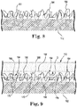
- FIGS. 8-10 are enlarged schematic cross-sectional views illustrating the formation of a drug eluting layer on the inner surface 158 of the ring 110.
- FIG. 8 shows a core pin or mandrel 162 and a plurality of nanofibers 164 disposed onto the core pin or mandrel 162.
- the plurality of nanofibers 164 can be similar or identical to the first plurality of nanofibers 138 described above in reference to FIGS. 3 and 4 .
- the plurality of nanofibers 164 can be electro-spun onto the core pin or mandrel 162.
- the core pin or mandrel 162 can be rotated while the plurality of nanofibers 164 is electro-spun onto the core pin or mandrel 162.
- the plurality of nanofibers 164 and the core pin or mandrel 162 can be over-molded with a ring body 166 to form the ring 110 with the inner surface 158, as shown in FIG. 9 .
- the ring body 166 can be formed of any suitable biostable, biocompatible polymer, such as a silicone or a polyurethane.
- the ring body 166 can be a polymer substrate.
- the body 166 can be made of silicone, in which case liquid silicone rubber is injected into a mold (not shown) containing the core pin or mandrel 162 and the plurality of nanofibers 164.
- the liquid silicone rubber does not fully penetrate through the plurality of nanofibers 164 to the core pin or mandrel 162 because of its relatively high viscosity and the relatively small size of the spaces formed among the plurality of nanofibers 164 as it is electro spun onto the core pin or mandrel 162.
- the inner surface 158 is spaced apart from the core pin or mandrel 162.
- Each nanofiber of the plurality of nanofibers 164 includes a first portion 168 and a second portion 170. Each nanofiber of the plurality of nanofibers 164 can wind its way into and out of the ring body 166 to define the first portion 168 and the second portion 170.
- the first portion 168 is defined as those portions of the nanofiber that are embedded in, or interpenetrated with, at least a portion of the ring body 166 at the inner surface 158.
- the first portion 168 can extend from the inner surface 158 into the ring body 166 to a depth D.
- the first portion 168 is mechanically fixed to the substrate by virtue of the embedded, interpenetrating structure.
- the second portion 170 is defined as those portions of the nanofiber that project from the inner surface 158.
- the projecting nanofibers of second portion 170 form a plurality of interstitial spaces, or pores 174, between adjacent nanofibers or portions of nanofibers of the plurality of nanofibers 164.
- the core pin or mandrel 162 can be removed, as shown in FIG. 10 , forming a drug eluting layer 172 on the inner surface 158 of the ring 110 similar to the embodiments described above in reference to FIG. 3 on the outer surface 130 of the suture sleeve 108.
- FIG. 11 is a schematic cross-sectional view of the portion of the ring 110 of FIG. 7 illustrating the drug eluting layer 172 on the inner surface 158 of the ring 110.
- the ring 110 can further include an antimicrobial drug component 176 disposed within at least some of the plurality of pores 174, thus forming the drug eluting layer 172.
- the antimicrobial drug component 176 can the same as any of the embodiments of the antimicrobial drug component 148 described above in reference to FIG. 4 .
- FIGS. 7-11 are directed to the drug eluting layer 172 formed on the inner surface 158 of the ring 110, it is understood that these disclosures may also be applied to the inner surface 132 of the suture sleeve 108.
- FIGS. 3-6 are directed to the drug eluting layer 145 formed on the outer surface 130 of the suture sleeve 108, it is understood that these disclosures may also be applied to the outer surface 156 of the ring 110.
- hydrophilic polymer examples include polyvinylpyrrolidone (PVP), poly(2-methyl-2-oxazoline), poly(2-ethyl-2-oxazoline, poly(ethylene glycol) methacrylate, and hydroxypropyl cellulose.
- PVP polyvinylpyrrolidone
- the hydrophilic polymer may be a hydroxy-terminated polymer, such as poly(ethylene glycol).
- the hydrophilic polymer may be terminated by a different functional group that may aid in cross-linking.
- the poly(ethylene glycol) can be terminated with a methacrylate group.
Landscapes
- Health & Medical Sciences (AREA)
- Life Sciences & Earth Sciences (AREA)
- Heart & Thoracic Surgery (AREA)
- General Health & Medical Sciences (AREA)
- Veterinary Medicine (AREA)
- Public Health (AREA)
- Vascular Medicine (AREA)
- Animal Behavior & Ethology (AREA)
- Surgery (AREA)
- Epidemiology (AREA)
- Chemical & Material Sciences (AREA)
- Engineering & Computer Science (AREA)
- Medicinal Chemistry (AREA)
- Biomedical Technology (AREA)
- Molecular Biology (AREA)
- Dispersion Chemistry (AREA)
- Bioinformatics & Cheminformatics (AREA)
- Cardiology (AREA)
- Nuclear Medicine, Radiotherapy & Molecular Imaging (AREA)
- Radiology & Medical Imaging (AREA)
- Materials For Medical Uses (AREA)
Description
- This application claims priority to Provisional Application No.
62/435,829, filed December 18, 2016 - The present invention relates to preventing infections associated with implantable medical devices. More specifically, the invention relates to an infection fighting drug eluting device for an implantable medical electrical lead.
- Medical devices may be implanted in a subcutaneous pocket to support sensing intrinsic physiological electrical activity, delivering a therapeutic stimulus to patient tissue, or providing other therapy to specific treatment sites. For example, a pulse generator may be implanted in a subcutaneous pocket in a patient's chest, with one or more electrical leads extending from the pulse generator to treatment sites within the patient.
- Implanting a medical device within a patient exposes the patient to a risk of a nosocomial (e.g., hospital-acquired) infection associated with bacteria adhering to the exterior of the medical device when it is placed within the subcutaneous pocket, causing a pocket infection. For example, the average nosocomial infection rate associated with the implantation of cardiovascular implantable electronic devices in 2008 was approximately 2.4 percent. In some cases of infection, the implantable medical device, including the device housing and any associated electrical leads, must be completely removed. Following removal, the infection must be cured and the patient must heal enough to tolerate implantation of a replacement medical device. The costs of such infections may be significant, not only intrinsically, but also in terms of the physical and emotional stress suffered by the patient.
- What is needed is a way to reduce the occurrence of infections which may result from implanting a medical device within a patient.
-
WO 2007078304 discloses implantable medical devices comprising nanostructure enhanced porous surfaces as well as their bacteriostatic properties.The nanostructures may comprise nanofibers. In one embodiment, the nanowires can be embedded (e.g. potted) in a plastic or polymer matrix material such as PTFE and then material can be partially removed such that the plastic or polymer matrix can protect most of the length of each nanofiber, leaving only portions of the nanowires such as their ends exposed for their desired intended application. - The medical device may further comprise one or more biologically compatible or bioactive coatings applied to the nanofibers.
- The scope of protection is defined by the claims.
- Example 1 is an implantable drug eluting medical device according to claim 1.
- Example 2 is the implantable medical device of Example 1, wherein the first plurality of nanofibers is formed of a bioresorbable polymer.
- Example 3 is the implantable medical device of Example 1, further including cross-linked poly(ethylene glycol) containing the at least one antimicrobial drug, the cross-linked poly(ethylene glycol) containing the at least one antimicrobial drug disposed within the first plurality of pores and mechanically fixed to the second portion of the first plurality of nanofibers.
- Example 4 is the implantable medical device of Example 3, wherein the cross-linked poly(ethylene glycol) containing the at least one antimicrobial drug is bonded to the second portion of the first plurality of nanofibers by covalent bonds.
- Example 5 is the implantable medical device of any of Examples 1-4, wherein the second plurality of nanofibers are thermally bonded to the first plurality of nanofibers.
- Example 6 is the implantable medical device of any of Examples 1-5, wherein the second plurality of pores has an average pore size that is smaller than an average pore size of the first plurality of pores.
- Example 7 is the implantable medical device of any of Examples 1-6, further comprising a second at least one antimicrobial drug disposed among the second plurality of nanofibers, wherein the second at least one antimicrobial drug can be the same or different than the at least one antimicrobial drug disposed within or among the second portion of the first plurality of nanofibers.
- Example 8 is a method of forming a drug eluting layer on a surface of a polymer substrate of an implantable medical device according to claim 8.
- Example 9 is the method of Example 8, wherein incorporating the at least one antimicrobial drug within pores formed by the second portion of the first plurality of nanofibers includes blending the at least one antimicrobial drug with a poly(ethylene glycol), disposing the blend of the at least one antimicrobial drug and the poly(ethylene glycol) into the pores, and cross-linking the poly(ethylene glycol) to mechanically fix the blend of the at least one antimicrobial drug and the poly(ethylene glycol) to the second portion of the first plurality of nanofibers.
- Example 10 is the method of Example 9, further including exposing the second portion of the first plurality of nanofibers and the blend of the at least one antimicrobial drug and the poly(ethylene glycol) to an argon-containing plasma to covalently bond the cross-linked poly(ethylene glycol) to the second portion of the first plurality of nanofibers.
- Example 11 is the method of any of Examples 8-10, wherein interpenetrating the first portion of the first plurality of nanofibers within the surface of the substrate includes electro-spinning the first plurality of nanofibers directly into the surface of the substrate.
- Example 12 is the method of any of Examples 8-10, wherein interpenetrating the first portion of the first plurality of nanofibers within the surface of the substrate includes electro-spinning the first plurality of nanofibers onto a core pin or a mandrel, and over-molding the surface of the substrate onto the first portion of the first plurality of nanofibers on the core pin or mandrel.
- Example 13 is the method of any of Examples 8-12, further comprising electro-spinning a second plurality of nanofibers onto the first plurality of nanofibers before incorporating at least one antimicrobial drug within pores formed by the second portion of the first plurality of nanofibers.
- The second plurality of nanofibers can be thermally bonded to the first plurality of nanofibers.
- The second plurality of pores has an average pore size that is smaller than an average pore size of the first plurality of pores.
- The implantable medical device may comprise a second at least one antimicrobial drug disposed among the second plurality of nanofibers, wherein the second at least one antimicrobial drug can be the same or different than the at least one antimicrobial drug disposed within or among the second portion of the first plurality of nanofibers.
- The implantable medical device may comprise a first plurality of nanofibers having an average diameter ranging from about 100 nanometers to about 1,000 nanometers.
- Electro-spinning a second plurality of nanofibers onto the first plurality of nanofibers can be carried out before incorporating at least one antimicrobial drug within pores formed by the second portion of the first plurality of nanofibers.
- Solidifying the surface of the substrate may include cross-linking the polymer substrate around the first portion of the first plurality of nanofibers.
-
-
FIG. 1 is a schematic illustration of implantable medical devices in accordance with some embodiments of the disclosure. -
FIG. 2 is a schematic cross-sectional view of a portion of the implantable medical electrical lead ofFIG. 1 showing a suture sleeve about the lead body. -
FIG. 3 is an enlarged schematic cross-sectional view of a portion of the suture sleeve ofFIG. 2 illustrating the outer surface of the suture sleeve. -
FIG. 4 is a schematic cross-sectional view of the portion of the suture sleeve ofFIG. 3 illustrating a drug eluting layer on the outer surface of the suture sleeve. -
FIG. 5 is a schematic cross-sectional view of the portion of the suture sleeve ofFIG. 4 illustrating a drug eluting layer on the outer surface of the suture sleeve, according to some embodiments. -
FIG. 6 is a schematic cross-sectional view of the portion of the suture sleeve ofFIG. 5 illustrating another embodiment of a drug eluting layer on the outer surface of the suture sleeve. -
FIG. 7 is a schematic cross-sectional view of a portion of the implantable medical electrical lead ofFIG. 1 showing a ring about the lead body. -
FIGS. 8, 9 , and10 are enlarged schematic cross-sectional views of a portion of the ring ofFIG. 7 illustrating the formation of a drug eluting layer on an inner surface of the ring. -
FIG. 11 is a schematic cross-sectional view of the portion of thering 110 ofFIG. 7 illustrating a drug eluting layer on the inner surface of the ring. - A more complete understanding of the present invention is available by reference to the following detailed description of numerous aspects and embodiments of the invention. The detailed description of the invention which follows is intended to illustrate but not limit the invention.
- In accordance with various aspects of the disclosure, it is understood that the various embodiments can be implemented in any suitable medical device implanted in a patient that includes an electrical lead electrically connected to the housing, such as the cardiac rhythm management (CRM) system described below. For example, embodiments may be employed with a subcutaneously-implanted implantable cardioverter-defibrillator (ICD) housing and lead system. Other such implantable medical devices include, without limitation, implantable cardiac monitors and neurostimulation systems such as spinal cord stimulation or deep brain stimulation devices.
-
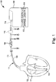
FIG. 1 is a schematic illustration of implantable medical devices in accordance with some embodiments of the disclosure.FIG. 1 shows a cardiac rhythm management (CRM)system 100 for delivering and/or receiving electrical pulses or signals to stimulate, shock, and/or sense aheart 102. TheCRM system 100 can include apulse generator 104, a medicalelectrical lead 106, asuture sleeve 108, and aring 110. Thepulse generator 104 includes apower source 112 as well aselectronic circuitry 114. Thepower source 112 may be a battery. Theelectronic circuitry 114 may be configured to generate a series of timed electrical discharges or pulses. Thepulse generator 104 may be implanted into a subcutaneous pocket made in the wall of the chest. Alternatively, thepulse generator 104 may be placed in a subcutaneous pocket made in the abdomen, or in another location. It should be noted that while the medicalelectrical lead 106 is illustrated for use with aheart 102, the medicalelectrical lead 106 is suitable for other forms of electrical stimulation/sensing as well. - In some embodiments, the medical
electrical lead 106 extends from aproximal end 116, where it is coupled with thepulse generator 104, to adistal end 118, which is coupled with a portion of theheart 102, when implanted or otherwise coupled therewith. The medicalelectrical lead 106 includes alead body 120 extending generally from theproximal end 116 to thedistal end 118. Thelead body 120 may be a tubular structure. Disposed along a portion of the medicalelectrical lead 106, for example near thedistal end 118, may be at least oneelectrode 122 which electrically couples the medicalelectrical lead 106 with theheart 102. At least one electrical conductor 124 (shown inFIG. 2 ) may be disposed within thelead body 120 and extend generally from theproximal end 116 to thedistal end 118. The at least oneelectrical conductor 124 electrically connects theelectrode 122 with theproximal end 116 of the medicalelectrical lead 106 to couple theelectrode 122 to thepulse generator 104. Theelectrical conductor 124 carries electrical current and pulses between thepulse generator 104 and theelectrode 122, and to and from theheart 102. - The medical
electrical lead 106 can be secured in place by thesuture sleeve 108 as described below in reference toFIG. 2 . Migration and dislodgment of the medicalelectrical lead 106 may be discouraged by securing thesuture sleeve 108 about thelead body 120 and suturing thesuture sleeve 108 to the patient's tissue. Thesuture sleeve 108 can be an implantable drug eluting device, according to embodiments of the disclosure. - Additionally or alternatively, the
ring 110 can also be a drug eluting device, according to embodiments of the disclosure. Thering 110 fits around thelead body 120 and may be disposed anywhere along the length of thelead body 120. Thering 110 can be an implantable drug eluting device, according to embodiments of the disclosure. - Embodiments according to the disclosure, such as the
suture sleeve 108 and thering 110, may elute at least one antimicrobial drug. The eluting antimicrobial drug can weaken or kill bacteria adhering to the surface of thesuture sleeve 108 or thering 110 as a result of, for example, thesuture sleeve 108 orring 110 being set down on operating spaces and/or being moved around during implantation of theCRM system 100. Once theCRM system 100 is implanted, a sufficient dosage of the at least one antimicrobial drug can elute from thesuture sleeve 108 within the subcutaneous pocket and/or thering 110 in the subcutaneous pocket or the venous pathway to reduce incidence and/or severity of a pocket infection or endocarditis. - In some embodiments, the at least one antimicrobial drug can include a broad-spectrum antibiotic, such as minocycline; or a narrow-spectrum antibiotic, such as rifampin. A broad-spectrum antibiotic is an antimicrobial drug that acts against a wide range of disease-causing bacteria, e.g. against both Gram-positive and Gram-negative bacteria. A narrow-spectrum antibiotic is an antimicrobial drug that acts against a single family of bacteria, e.g. Gram-positive or Gram-negative, but not both. In some embodiments, the at least one antimicrobial drug can include a combination of a broad-spectrum antibiotic and a narrow-spectrum antibiotic, such as a combination of minocycline and rifampin. In some embodiments, the at least one antimicrobial drug can include daptomycin, sulfonamide drugs, β-lactams, and/or vancomycin.
- Although the embodiment shown in
FIG. 1 is illustrated with onesuture sleeve 108 and onering 110, it is understood that embodiments may include only one of either thesuture sleeve 108 or thering 110. Embodiments may also include more than onesuture sleeve 108 and/or more than onering 110. For example,more rings 110 may be added to increase the dosage of the at least one antimicrobial drug delivered to the subcutaneous pocket. -
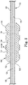
FIG. 2 is a schematic cross-sectional view of a portion of the implantable medicalelectrical lead 106 ofFIG. 1 showing thesuture sleeve 108 about thelead body 120. In the embodiment shown inFIG. 2 , thelead body 120 includes atubular structure 126 defining alead lumen 128. Theelectrical conductor 124 extends through thelead lumen 128 from theproximal end 116 to the electrode 122 (FIG. 1 ). Thesuture sleeve 108 includes anouter surface 130 and aninner surface 132. In the embodiment ofFIG. 2 , thesuture sleeve 108 also includes at least one suture groove 134 (three shown) in theouter surface 130 extending around the circumference of thesuture sleeve 108. Theinner surface 132 defines asuture sleeve lumen 136 extending the length of thesuture sleeve 108. A diameter of thesuture sleeve lumen 136 is greater than a diameter of thelead body 120 such that thesuture sleeve lumen 136 may be moved along thelead body 120 to a position adjacent to tissue suitable for attachment. Once thesuture sleeve lumen 136 is positioned adjacent to tissue, sutures (not shown) may be tightly wrapped around thesuture sleeve 108 in thesuture grooves 134 and sutured to the patient's tissue. The tightly wrapped sutures in thesuture grooves 134 can compress theinner surface 132 of thesuture sleeve 108 adjacent to thesuture grooves 134 against thelead body 120, securing thelead body 120 within thesuture sleeve 108. - The
suture sleeve 108 can be drug eluting, as describe below. It has been found that bacteria may migrate along thelead body 120. Bacteria growth can be particularly aggressive under the edge of thesuture sleeve 108 insuture sleeve lumen 136. The antimicrobial drug eluting fromsuture sleeve 108 can kill bacteria along thelead body 120 and within the pocket adjacent to thesuture sleeve 108 to reduce pocket infections, bacteremia, or endocarditis. -
FIG. 3 (not according to the invention) is an enlarged schematic cross-sectional view of a portion of thesuture sleeve 108 ofFIG. 2 illustrating theouter surface 130 of thesuture sleeve 108. As shown inFIG. 3 , thesuture sleeve 108 includes a first plurality ofnanofibers 138 and asuture sleeve body 140. Thesuture sleeve body 140 can be formed of any suitable biostable, biocompatible polymer, such as a silicone or a polyurethane. Thus, thesuture sleeve body 140 can be a polymer substrate. Thesuture sleeve body 140 can be formed by any suitable means including, for example, by molding. Each nanofiber of the first plurality ofnanofibers 138 includes afirst portion 142 and asecond portion 144. Each nanofiber of the first plurality ofnanofibers 138 can wind its way into and out of thesuture sleeve body 140 to define thefirst portion 142 and thesecond portion 144. Thefirst portion 142 is defined as those portions of the nanofiber that are embedded in, or interpenetrated with, at least a portion of thesuture sleeve body 140 at theouter surface 130. Thefirst portion 142 can extend from theouter surface 130 into thesuture sleeve body 140 to a depth D. Thefirst portion 142 is mechanically fixed to the substrate by virtue of the embedded, interpenetrating structure. - The
second portion 144 is defined as those portions of the nanofiber that project from theouter surface 130. The projecting nanofibers ofsecond portion 144 form a first plurality of interstitial spaces, or pores 146, between adjacent nanofibers or portions of nanofibers of the first plurality ofnanofibers 138. - The depth D to which the
first portion 142 extends may be as small as about 10 microns, about 20 microns, or about 30 microns, or as great as about 50 microns, about 60 microns, or about 125 microns, or may extend an amount within any range defined between any pair of the foregoing values. The depth D may range from about 10 microns to about 125 microns, about 20 microns to about 60 microns, or about 30 microns to about 50 microns. The depth D may be about 40 microns. - The first plurality of
nanofibers 138 can have an average diameter as small as about 100 nanometers, about 200 nanometers, or about 400 nanometers, or as large as about 600 nanometers, about 800 nanometers, or about 1,000 nanometers, or have an average diameter between any of the preceding average diameters. The average diameter of the first plurality ofnanofibers 138 can range from about 100 nanometers to about 1,000 nanometers, about 200 nanometers to about 800 nanometers, or about 400 nanometers to about 600 nanometers. The average diameter may be determined by averaging measurements of the average diameter among the first plurality ofnanofibers 138. The size of the first plurality ofpores 146 may vary with the average diameter of the first plurality ofnanofibers 138, with a larger average diameter resulting in a larger average size of the first plurality ofpores 146. - The first plurality of
nanofibers 138 may include any suitable biocompatible polymer that can be formed into nanofibers. In some embodiments in which the first plurality ofnanofibers 138 is biostable, the first plurality ofnanofibers 138 can include a fluoropolymer, such as polytetrafluoroethylene (PTFE), polyvinlyidene fluoride (PVDF), or poly(vinylidene fluoride-co-hexafluoropropene) (PVDF-HPV); a polyurethane, such as polyether polyurethane, polycarbonate polyurethane, or polyisobutylene-polyurethane (PIB-PUR); or styrene-isobutylene-styrene (SIBS). In other embodiments in which the first plurality ofnanofibers 138 is bioresorbable, the first plurality ofnanofibers 138 can include poly(lactic-co-glycolic) acid (PLGA), polycaprolactone (PCL), poly-L-lactide (PLLA), or poly(lactide-co-glycolide)-block-poly(ethylene glycol). The first plurality ofnanofibers 138 can be formed by electro-spinning, as is known in the art. - The
first portion 142 of the first plurality ofnanofibers 138 is interpenetrated with or embedded in thesuture sleeve body 140 while thesuture sleeve body 140 is in a liquid or semi-liquid state and thesecond portion 144 projects away from theouter surface 130. When thesuture sleeve body 140 solidifies, thefirst portion 142 is embedded in thesuture sleeve body 140 and thesecond portion 144 projects away from theouter surface 130. Thesuture sleeve body 140 can be made of a thermoset polymer, such as a silicone, thefirst portion 142 of the first plurality ofnanofibers 138 can be interpenetrated with thesuture sleeve body 140 while the polymer is in a liquid or semi-liquid state before it is solidified by curing or cross-linking portions of the polymer around portions of thefirst portion 142. When thesuture sleeve body 140 is made of a thermoplastic polymer, the first plurality ofnanofibers 138 can be interpenetrated with thesuture sleeve body 140 while the polymer is in a liquid or semi-liquid state created by heating the polymer to melt or soften a portion of thesuture sleeve body 140 at theouter surface 130, or by dissolution of the portion of thesuture sleeve body 140 at theouter surface 130 in a suitable solvent. For example, if thesuture sleeve body 140 is formed of a polyurethane, then tetrahydrofuran or dimethylformamide may be used to soften thesuture sleeve body 140, creating a semi-liquid state. Once thefirst portion 142 of the first plurality ofnanofibers 138 has interpenetrated thesuture sleeve body 140, thesuture sleeve body 140 can be cooled, or the solvent permitted to evaporate, to solidify thesuture sleeve body 140, mechanically fixing thefirst portion 142 within thesuture sleeve body 140. - Interpenetrating the
first portion 142 of the first plurality ofnanofibers 138 within thesuture sleeve body 140 may include electro-spinning a nanofiber directly into thesuture sleeve body 140 while the portion of thesuture sleeve body 140 at theouter surface 130 is in a liquid or semi-liquid state. - The at least one antimicrobial drug can be blended with a bioresorbable polymer, such as any mentioned above, and the first plurality of
nanofibers 138 formed from this blend by electro-spinning, thus forming adrug eluting layer 145. The antimicrobial drug is disposed within the first plurality ofnanofibers 138. That is, the antimicrobial drug is integrated into the bioresorbable polymer itself such that as the bioresorbable polymer is broken down by the body, the antimicrobial drug is released from the first plurality ofnanofibers 138. In this way, the antimicrobial drug and the plurality ofnanofibers 138 can be configured to elute the antimicrobial drug from within the first plurality ofnanofibers 138 as they are bioresorbed by the body. As used herein, a bioresorbable polymer is a polymer that may be broken down by biological systems to such an extent that it may be completely eliminated from the body. This is in contrast to a bioabsorbable polymer which is a polymer that may be broken down by biological systems, but not necessarily to the extent that it may be completely eliminated from the body. -
FIG. 4 is a schematic cross-sectional view of the portion of thesuture sleeve 108 ofFIG. 3 illustrating another alternative of thedrug eluting layer 145 on theouter surface 130 of thesuture sleeve 108. As shown in the embodiment ofFIG. 4 , thesuture sleeve 108 can further includes anantimicrobial drug component 148 disposed within at least some of the first plurality orpores 146, thus forming thedrug eluting layer 145. Theantimicrobial drug component 148 can consist of one or more antimicrobial drugs contained in the first plurality ofpores 146. The rate of elution of the one or more antimicrobial drugs can be controlled by the size of the first plurality ofpores 146, with smaller pores resulting in a lower elution rate. Theantimicrobial drug component 148 can include a colloid suspension of the one or more antimicrobial drugs. The colloid suspension may be stabilized by addition of poly(ethylene glycol). - The
antimicrobial drug component 148 further includes a suitable hydrophilic polymer, such as poly(ethylene glycol), that has been blended with the least one antimicrobial drug. After being disposed within thepores 146 by, for example, diffusion or absorption, and then cross-linked around and between at least some of thesecond portion 144 to mechanically fix theantimicrobial drug component 148 to the first plurality ofnanofibers 138. In this way, the at least one antimicrobial drug and the plurality ofnanofibers 138 can be configured to elute the antimicrobial drug from among the first plurality ofnanofibers 138. - The poly(ethylene glycol) can include a radical initiator compound that generates free radicals when exposed to energy, such as ultraviolet radiation or heat. The free radicals can initiate cross-linking of the poly(ethylene glycol). Examples of suitable UV initiator compounds include (4-bromophenyl)diphenylsulfonium triflate, (4-fluorophenyl)diphenylsulfonium triflate, (4-iodophenyl)diphenylsulfonium triflate, (4-methoxyphenyl)diphenylsulfonium triflate, (4-methylphenyl)diphenylsulfonium triflate, (4-methylthiophenyl)methyl phenyl sulfonium triflate, (4-phenoxyphenyl)diphenylsulfonium triflate, (4-phenylthiophenyl)diphenylsulfonium triflate, (4-tert-butylphenyl)diphenylsulfonium triflate, (cumene)cyclopentadienyliron(II) hexafluorophosphate, (tert-butoxycarbonylmethoxynaphthyl)-diphenylsulfonium triflate, 1-naphthyl diphenylsulfonium triflate, 2-(4-methoxystyryl)-4,6-bis(trichloromethyl)-1,3,5-triazine, bis(4-tert-butylphenyl)iodonium perfluoro-1-butanesulfonate , bis(4-tert-butylphenyl)iodonium p-toluenesulfonate, bis(4-tert-butylphenyl)iodonium triflate, boc-methoxyphenyldiphenylsulfonium triflate, diphenyliodonium hexafluorophosphate, diphenyliodonium nitrate, diphenyliodonium perfluoro-1-butanesulfonate, diphenyliodonium p-toluenesulfonate, diphenyliodonium triflate, N-hydroxy-5-norbornene-2,3-dicarboximide perfluoro-1-butanesulfonate, N-hydroxynaphthalimide triflate, triarylsulfonium hexafluoroantimonate salts, triphenylsulfonium perfluoro-1-butanesufonate, triphenylsulfonium triflate, tris(4-tert-butylphenyl)sulfonium perfluoro-1-butanesulfonate, and tris(4-tert-butylphenyl)sulfonium triflate. Examples of suitable thermal initiator compounds include azobisisobutyronitrile (AIBN), dibenzoyl peroxide, N-benzyl pyridinium bromide, N-benzyl o-cyano pyridinium bromide, N-benzyl p-cyanopyridinium bromide, N-benzyl N, N-dimethyl anilinium bromide, and benzyl triphenyl phosphonium bromide.
- Thus the cross-linked poly(ethylene glycol) of the
antimicrobial drug component 148 can include a residue of a cross-linking initiator. For example, the initiator residue may include, for example, a residue of any of the ultraviolet initiators or the thermal initiators describe above. - According to
FIG. 4 , thesecond portion 144 of the first plurality ofnanofibers 138 can be formed as described above in reference toFIG. 3 , and coated with theantimicrobial drug component 148 so that it can be disposed into the first plurality ofpores 146. Coating thesecond portion 144 with theantimicrobial drug component 148 can included dipping theouter surface 130 into the at least one antimicrobial drug or the blend of the at least one antimicrobial drug and the poly(ethylene glycol) in a liquid state. Coating thesecond portion 144 with theantimicrobial drug component 148 can include spraying the at least one antimicrobial drug or the blend of the at least one antimicrobial drug and the poly(ethylene glycol) in a liquid state onto theouter surface 130. - The cross-linked poly(ethylene glycol) of the
antimicrobial drug component 148 can be covalently bonded to thesecond portion 144 of the first plurality ofnanofibers 138, in addition to being mechanically fixed to thesecond portion 144. The cross-linked poly(ethylene glycol) is both chemically and mechanically fixed to thesecond portion 144. Incorporating theantimicrobial drug component 148 into the first plurality ofpores 146 can include exposing thesecond portion 144 and theantimicrobial drug component 148 including the poly(ethylene glycol) and the at least one antimicrobial drug to a plasma that contains argon. Free radicals formed by the argon-containing plasma produce reactive sites for covalent bonding of the poly(ethylene glycol) to thesecond portion 144 of the first plurality ofnanofibers 138. The argon-containing plasma does not include oxygen, as the oxygen has been found to deteriorate the first plurality ofnanofibers 138. The argon-containing plasma can produced from a flow of argon gas at a pressure of about 250 mTorr and an applied radio-frequency power of about 200 Watts. Thesecond portion 144 and the first plurality ofnanofibers 138 can be exposed to the plasma for a time ranging from about 60 seconds to about 180 seconds. - The free radicals generated by exposure to the argon-containing plasma not only provide reactive sites for covalent bonding of the poly(ethylene glycol) to the
second portion 144, but may also provide free radicals for the cross-linking of the poly(ethylene glycol). There may be no need for an ultraviolet initiator or a thermal initiator, and no initiator residues present in the cross-linked poly(ethylene glycol) portion of theantimicrobial drug component 148. -
FIG. 5 is a schematic cross-sectional view of the portion of thesuture sleeve 108 ofFIG. 4 illustrating an embodiment of thedrug eluting layer 145 on theouter surface 130 of thesuture sleeve 108. As shown in the embodiment ofFIG. 5 , thesuture sleeve 108 includes a second plurality ofnanofibers 150 disposed on the first plurality ofnanofibers 138. The second plurality ofnanofibers 150 may be formed by electro-spinning, as with the first plurality ofnanofibers 138, forming a second plurality of interstitial spaces, or pores 152, betweenadjacent nanofibers 150. The second plurality ofnanofibers 150 withpores 152 can limit the rate of elution of the one or more antimicrobial drugs from theantimicrobial drug component 148 by providing a barrier through which the antimicrobial drugs must diffuse. - In some embodiments, the second plurality of
nanofibers 150 can be formed on the first plurality ofnanofibers 138 by electro-spinning. In some embodiments, the second plurality ofnanofibers 150 can be electro-spun onto the first plurality ofnanofibers 138 before incorporating theantimicrobial drug component 148 within the first plurality ofpores 146, as described above in reference toFIG. 4 . In some other embodiments, the second plurality ofnanofibers 150 can be electro-spun onto the first plurality ofnanofibers 138 after incorporating theantimicrobial drug component 148 within the first plurality ofpores 146, as described above in reference toFIG. 4 . - In some embodiments, the second plurality of
nanofibers 150 can be partially interwoven with the first plurality ofnanofibers 138 as a result of electro-spinning the second plurality ofnanofibers 150 directly onto the first plurality ofnanofibers 138. In some embodiments, the second plurality ofnanofibers 150 can be thermally bonded to the first plurality ofnanofibers 138. - In some embodiments, the second plurality of
nanofibers 150 may include any suitable biocompatible polymer that can be formed into nanofibers. In some embodiments in which the second plurality ofnanofibers 150 is biostable, the second plurality ofnanofibers 150 can include a fluoropolymer, such as polytetrafluoroethylene (PTFE), polyvinlyidene fluoride (PVDF), or poly(vinylidene fluoride-co-hexafluoropropene) (PVDF-HPV); a polyurethane, such as polyether polyurethane, polycarbonate polyurethane, or polyisobutylene-polyurethane (PIB-PUR); or styrene-isobutylene-styrene (SIBS). In some embodiments, the second plurality ofnanofibers 150 can be formed by electro-spinning, as is known in the art. - In some embodiments, the second plurality of
nanofibers 150 can have an average diameter as small as about 100 nanometers, about 200 nanometers, or about 400 nanometers, or as large as about 600 nanometers, about 800 nanometers, or about 1,000 nanometers, or have an average diameter between any of the preceding average diameters. In some embodiments, the average diameter of second plurality ofnanofibers 150 can range from about 100 nanometers to about 1,000 nanometers, about 200 nanometers to about 800 nanometers, or about 400 nanometers to about 600 nanometers. The average diameter may be determined by averaging measurements of the average diameter among the second plurality ofnanofibers 150. The size of the second plurality ofpores 152 may vary with the average diameter of the second plurality ofnanofibers 150, with a larger average diameter resulting in a larger average size of the second plurality ofpores 152. In some embodiments, the size of the second plurality ofpores 152 can be smaller than the size of the first plurality ofpores 146 to further limit the rate of elution of the one or more antimicrobial drugs from theantimicrobial drug component 148. -
FIG. 6 is a schematic cross-sectional view of the portion of thesuture sleeve 108 ofFIG. 5 illustrating another embodiment of thedrug eluting layer 145 on theouter surface 130 of thesuture sleeve 108. As shown in the embodiment ofFIG. 6 , thesuture sleeve 108 can further includes anantimicrobial drug component 154 disposed within at least some of the second plurality ofpores 152. Theantimicrobial drug component 154 can be as described above for any of the embodiments of theantimicrobial drug component 148. The rate of elution of the one or more antimicrobial drugs can be controlled by the size of the second plurality ofpores 152, with smaller pores resulting in a lower elution rate. - In some embodiments, the
antimicrobial drug component 154 can be identical to theantimicrobial drug component 148. In other embodiments, theantimicrobial drug component 154 can be different from theantimicrobial drug component 148. For example, in some embodiments, theantimicrobial drug component 154 may be configured to elute over a shorter period of time to provide a strong, initial dose against any bacteria on thesuture sleeve 108 at the time of implantation, while theantimicrobial drug component 148 may be configured to elute over a longer period of time to provide on-going antimicrobial protection within the subcutaneous pocket. In some embodiments, the period of time for theantimicrobial drug component 154 to elute can be up to 2 hours, up to 4 hours, or up to 6 hours or up to any time between any to the preceding times. In some embodiments, the period of time for theantimicrobial drug component 148 to elute can be up to 6 hours, up to 10 hours, up to 24 hours, up to 2 days, up to 4 days, up to 6 days, up to 1 week, up to 2 weeks, up to 3 weeks, up to 4 weeks, up to 2 months, up to 4 months, or up to 6 months, or up to any period of time between any two of the preceding times. -
FIGS. 7-11 describe a drug eluting layer on an inner surface of the ring 110 (not according to the invention).FIG. 7 is a schematic cross-sectional view of a portion of the implantable medicalelectrical lead 106 ofFIG. 1 showing thering 110 about thelead body 120. As shown inFIG. 7 , thering 110 includes anouter surface 156 and aninner surface 158. Theinner surface 158 defines aring lumen 160 extending the length of thering 110. A diameter of thering lumen 160 is greater than a diameter of thelead body 120 such that thering lumen 160 may be moved along thelead body 120 to a suitable location within the subcutaneous pocket. - The
ring 110 can be drug eluting, as describe below. It has been found that bacteria may migrate along thelead body 120. As with thesuture sleeve 108 described above, the antimicrobial drug eluting fromring 110 can kill bacteria along thelead body 120 and within the pocket to reduce pocket infections, bacteremia, or endocarditis. -
FIGS. 8-10 are enlarged schematic cross-sectional views illustrating the formation of a drug eluting layer on theinner surface 158 of thering 110.FIG. 8 shows a core pin ormandrel 162 and a plurality ofnanofibers 164 disposed onto the core pin ormandrel 162. The plurality ofnanofibers 164 can be similar or identical to the first plurality ofnanofibers 138 described above in reference toFIGS. 3 and 4 . The plurality ofnanofibers 164 can be electro-spun onto the core pin ormandrel 162. The core pin ormandrel 162 can be rotated while the plurality ofnanofibers 164 is electro-spun onto the core pin ormandrel 162. - After the plurality of
nanofibers 164 is formed onto the core pin ormandrel 162, the plurality ofnanofibers 164 and the core pin ormandrel 162 can be over-molded with aring body 166 to form thering 110 with theinner surface 158, as shown inFIG. 9 . Thering body 166 can be formed of any suitable biostable, biocompatible polymer, such as a silicone or a polyurethane. Thus, thering body 166 can be a polymer substrate. For example, thebody 166 can be made of silicone, in which case liquid silicone rubber is injected into a mold (not shown) containing the core pin ormandrel 162 and the plurality ofnanofibers 164. The liquid silicone rubber does not fully penetrate through the plurality ofnanofibers 164 to the core pin ormandrel 162 because of its relatively high viscosity and the relatively small size of the spaces formed among the plurality ofnanofibers 164 as it is electro spun onto the core pin ormandrel 162. Thus, theinner surface 158 is spaced apart from the core pin ormandrel 162. - Each nanofiber of the plurality of
nanofibers 164 includes afirst portion 168 and asecond portion 170. Each nanofiber of the plurality ofnanofibers 164 can wind its way into and out of thering body 166 to define thefirst portion 168 and thesecond portion 170. Thefirst portion 168 is defined as those portions of the nanofiber that are embedded in, or interpenetrated with, at least a portion of thering body 166 at theinner surface 158. Thefirst portion 168 can extend from theinner surface 158 into thering body 166 to a depth D. Thefirst portion 168 is mechanically fixed to the substrate by virtue of the embedded, interpenetrating structure. - The
second portion 170 is defined as those portions of the nanofiber that project from theinner surface 158. The projecting nanofibers ofsecond portion 170 form a plurality of interstitial spaces, or pores 174, between adjacent nanofibers or portions of nanofibers of the plurality ofnanofibers 164. - After the silicone cross-links or cures, the core pin or
mandrel 162 can be removed, as shown inFIG. 10 , forming adrug eluting layer 172 on theinner surface 158 of thering 110 similar to the embodiments described above in reference toFIG. 3 on theouter surface 130 of thesuture sleeve 108. -
FIG. 11 is a schematic cross-sectional view of the portion of thering 110 ofFIG. 7 illustrating thedrug eluting layer 172 on theinner surface 158 of thering 110. As shown inFIG. 11 , thering 110 can further include anantimicrobial drug component 176 disposed within at least some of the plurality ofpores 174, thus forming thedrug eluting layer 172. Theantimicrobial drug component 176 can the same as any of the embodiments of theantimicrobial drug component 148 described above in reference toFIG. 4 . - Although
FIGS. 7-11 are directed to thedrug eluting layer 172 formed on theinner surface 158 of thering 110, it is understood that these disclosures may also be applied to theinner surface 132 of thesuture sleeve 108. Similarly, althoughFIGS. 3-6 are directed to thedrug eluting layer 145 formed on theouter surface 130 of thesuture sleeve 108, it is understood that these disclosures may also be applied to theouter surface 156 of thering 110. - Although poly(ethylene glycol) is described as the hydrophilic polymer in the above embodiments, other suitable hydrophilic polymers can include polyvinylpyrrolidone (PVP), poly(2-methyl-2-oxazoline), poly(2-ethyl-2-oxazoline, poly(ethylene glycol) methacrylate, and hydroxypropyl cellulose. In some embodiments, the hydrophilic polymer may be a hydroxy-terminated polymer, such as poly(ethylene glycol). In other embodiments, the hydrophilic polymer may be terminated by a different functional group that may aid in cross-linking. For example, the poly(ethylene glycol) can be terminated with a methacrylate group.
Claims (15)
- An implantable drug eluting medical device (100) comprising:- a polymer substrate (140) having a surface (130);- a first plurality of nanofibers (138), each nanofiber (138) including:- a first portion (142) interpenetrated with the surface (130) of the substrate (140) to mechanically fix the nanofiber (138) to the substrate (140); and- a second portion (144) projecting from the surface (130), the second portion (144) of the first plurality of nanofibers (138) forming a first plurality of pores (146);- a second plurality of nanofibers (150) disposed on the first plurality of nanofibers (138), the second plurality of nanofibers (150) forming a second plurality of pores (152); and- at least one antimicrobial drug (148) disposed within at least some of the first plurality of pores (146).
- The implantable medical device (100) of claim 1, wherein the first plurality of nanofibers (138) is formed of a bioresorbable polymer.
- The implantable medical device (100) of claim 1, further including cross-linked poly(ethylene glycol) containing the at least one antimicrobial drug (148), the cross-linked poly(ethylene glycol) containing the at least one antimicrobial drug (148) disposed within the first plurality of pores (146)and mechanically fixed to the second portion (144) of the first plurality of nanofibers (138).
- The implantable medical device (100) of claim 3, wherein the cross-linked poly(ethylene glycol) containing the at least one antimicrobial drug (148) is bonded to the second portion (144) of the first plurality of nanofibers (138) by covalent bonds.
- The implantable medical device (100) of any of claims 1-4, wherein the second plurality of nanofibers (150) are thermally bonded to the first plurality of nanofibers (138).
- The implantable medical device (100) of any of claims 1-5, wherein the second plurality of pores (152) has an average pore size that is smaller than an average pore size of the first plurality of pores (146).
- The implantable medical device (100) of any of claims 1-6, further comprising a second at least one antimicrobial drug (148) disposed among the second plurality of nanofibers (150), wherein the second at least one antimicrobial drug (148) can be the same or different than the at least one antimicrobial drug (148) disposed within the second portion (144) of the first plurality of nanofibers (138).
- A method of forming a drug eluting layer (145) on a surface (130) of a polymer substrate (140) of an implantable medical device (100), the method comprising:- interpenetrating a first portion (142) of a first plurality of nanofibers (138) within the surface (130) of the substrate (140), the surface (130) of the substrate (140) being in a liquid or semi-liquid state;- solidifying the surface (130) of the substrate (140), wherein the first portion (142) of the first plurality of nanofibers (138) is mechanically fixed within the surface (130) of the substrate (140) and a second portion (144) of the first plurality of nanofibers (138) projects away from the surface (130);- incorporating at least one antimicrobial drug (148) within a first plurality of pores (146) formed by the second portion (144) of the first plurality of nanofibers (138); and- electro-spinning a second plurality of nanofibers (150) onto the first plurality of nanofibers (138), the second plurality of nanofibers (150) forming a second plurality of pores (152).
- The method of claim 8, wherein incorporating the at least one antimicrobial drug (148) within pores (146) formed by the second portion (144) of the first plurality of nanofibers (138) includes:- blending the at least one antimicrobial drug (148) with a poly(ethylene glycol);- disposing the blend of the at least one antimicrobial drug (148) and the poly(ethylene glycol) into the pores (146); and- cross-linking the poly(ethylene glycol) to mechanically fix the blend of the at least one antimicrobial drug (148) and the poly(ethylene glycol) to the second portion (144) of the first plurality of nanofibers (138).
- The method of claim 9, further including exposing the second portion (144) of the first plurality of nanofibers (138) and the blend of the at least one antimicrobial drug (148) and the poly(ethylene glycol) to an argon-containing plasma to covalently bond the cross-linked poly(ethylene glycol) to the second portion (144) of the first plurality of nanofibers (138).
- The method of any of claims 8-10, wherein interpenetrating the first portion (168) of the first plurality of nanofibers (164) within the surface (158) of the substrate (166) includes electro-spinning the first plurality of nanofibers (164) directly into the surface (158) of the substrate (166).
- The method of any of claims 8-10, wherein interpenetrating the first portion (168) of the first plurality of nanofibers (164) within the surface (158) of the substrate (166) includes:- electro-spinning the first plurality of nanofibers (164) onto a core pin or a mandrel (162); and- over-molding the surface (158) of the substrate (166) onto the first portion (168) of the first plurality of nanofibers (164) on the core pin or mandrel (162).
- The method of any of claims 8-12, wherein electro-spinning the second plurality (150) of nanofibers onto the first plurality of nanofibers (138, 164) is before incorporating the at least one antimicrobial drug (148, 154, 176) within the first plurality of pores (146, 174) formed by the second portion (144, 170) of the first plurality of nanofibers (138, 164).
- The method of any of claims 8-13, wherein electro-spinning the second plurality of nanofibers (150) onto the first plurality of nanofibers (138, 164) is after incorporating the at least one antimicrobial drug (148, 154, 176) within the first plurality of pores (146, 174) formed by the second portion (144, 170) of the first plurality of nanofibers (138, 164).
- The method of any of claims 8-14, further comprising incorporating a second at least one antimicrobial drug (148, 154, 176) within the second plurality of pores (152) formed by the second plurality of nanofibers (150).
Applications Claiming Priority (2)
| Application Number | Priority Date | Filing Date | Title |
|---|---|---|---|
| US201662435829P | 2016-12-18 | 2016-12-18 | |
| PCT/US2017/066690 WO2018112355A1 (en) | 2016-12-18 | 2017-12-15 | Infection fighting drug eluting device |
Publications (2)
| Publication Number | Publication Date |
|---|---|
| EP3554572A1 EP3554572A1 (en) | 2019-10-23 |
| EP3554572B1 true EP3554572B1 (en) | 2021-03-03 |
Family
ID=60997547
Family Applications (1)
| Application Number | Title | Priority Date | Filing Date |
|---|---|---|---|
| EP17830060.4A Active EP3554572B1 (en) | 2016-12-18 | 2017-12-15 | Infection fighting drug eluting device |
Country Status (4)
| Country | Link |
|---|---|
| US (1) | US10518004B2 (en) |
| EP (1) | EP3554572B1 (en) |
| CN (1) | CN110087704B (en) |
| WO (1) | WO2018112355A1 (en) |
Families Citing this family (1)
| Publication number | Priority date | Publication date | Assignee | Title |
|---|---|---|---|---|
| CN110087704B (en) * | 2016-12-18 | 2022-06-10 | 心脏起搏器股份公司 | Anti-infective drug outflow device |
Family Cites Families (27)
| Publication number | Priority date | Publication date | Assignee | Title |
|---|---|---|---|---|
| CA1245931A (en) | 1984-09-21 | 1988-12-06 | Sophia Pesotchinsky | Positionable tissue interfacing device for the management of percutaneous conduits |
| US5154182A (en) | 1991-02-15 | 1992-10-13 | Siemens Pacesetter, Inc. | Drug or steroid releasing patch electrode for an implantable arrhythmia treatment system |
| WO1993007924A1 (en) | 1991-10-18 | 1993-04-29 | Spire Corporation | Bactericidal coatings for implants |
| US5217493A (en) | 1992-03-11 | 1993-06-08 | Board Of Regents, The University Of Texas System | Antibacterial coated medical implants |
| US6267782B1 (en) | 1997-11-20 | 2001-07-31 | St. Jude Medical, Inc. | Medical article with adhered antimicrobial metal |
| US5861023A (en) | 1997-12-16 | 1999-01-19 | Pacesetter, Inc. | Thrombus and tissue ingrowth inhibiting overlays for defibrillator shocking coil electrodes |
| US6451003B1 (en) | 2000-08-16 | 2002-09-17 | Biolink Corporation | Method and apparatus for overcoming infection in a tissue pocket surrounding an implanted device |
| US7363091B1 (en) | 2001-07-11 | 2008-04-22 | Pacesetter Inc. | Method of molding silicone elastomer drug carrier in an endocardial lead |
| KR20040077753A (en) | 2002-01-22 | 2004-09-06 | 파마시아 앤드 업존 캄파니 | Infection-resistant medical devices |
| US7507230B2 (en) | 2002-02-19 | 2009-03-24 | Boston Scientific Scimed, Inc. | Medical catheter assembly including multi-piece connector |
| US7067606B2 (en) | 2002-07-30 | 2006-06-27 | University Of Connecticut | Nonionic telechelic polymers incorporating polyhedral oligosilsesquioxane (POSS) and uses thereof |
| GB0222522D0 (en) | 2002-09-27 | 2002-11-06 | Controlled Therapeutics Sct | Water-swellable polymers |
| US20050038498A1 (en) * | 2003-04-17 | 2005-02-17 | Nanosys, Inc. | Medical device applications of nanostructured surfaces |
| US7972616B2 (en) | 2003-04-17 | 2011-07-05 | Nanosys, Inc. | Medical device applications of nanostructured surfaces |
| US8025960B2 (en) * | 2004-02-02 | 2011-09-27 | Nanosys, Inc. | Porous substrates, articles, systems and compositions comprising nanofibers and methods of their use and production |
| US20090204129A1 (en) * | 2005-03-22 | 2009-08-13 | Leslie Fronio | Bioactive wide-weave mesh |
| US8430852B2 (en) | 2007-04-17 | 2013-04-30 | Medtronic, Inc. | Therapeutic sleeve for implantable medical device |
| WO2008131089A2 (en) | 2007-04-17 | 2008-10-30 | Medtronic, Inc. | Reduction of infection associated with medical device |
| US9211252B2 (en) | 2007-04-27 | 2015-12-15 | Medtronic, Inc. | Increased drug loading capacity of polymeric material |
| CN101187111B (en) * | 2007-11-29 | 2011-04-27 | 东华大学 | Composite nanometer fiber felt containing nano silver gelatin/chitosan for medical dressing and its preparation |
| US8209016B2 (en) | 2009-03-20 | 2012-06-26 | Medtronic, Inc. | Implantable lead management |
| WO2013123507A1 (en) * | 2012-02-17 | 2013-08-22 | Bacterin International, Inc. | Composition of and method for forming reduced viscosity polymeric coatings |
| CN103394114B (en) * | 2013-07-03 | 2016-08-10 | 东华大学 | A kind of preparation method of medical dressing chitosan-based superfine fiber carrier material |
| US20150025608A1 (en) | 2013-07-22 | 2015-01-22 | Cardiac Pacemakers, Inc. | Lubricious, biocompatible hydrophilic thermoset coating using interpenetrating hydrogel networks |
| WO2016025945A1 (en) * | 2014-08-15 | 2016-02-18 | The Johns Hopkins University Technology Ventures | Composite material for tissue restoration |
| AU2015364546B2 (en) | 2014-12-18 | 2018-05-10 | Cardiac Pacemakers, Inc. | Fibrous joinery interface between structures |
| CN110087704B (en) * | 2016-12-18 | 2022-06-10 | 心脏起搏器股份公司 | Anti-infective drug outflow device |
-
2017
- 2017-12-15 CN CN201780078226.5A patent/CN110087704B/en active Active
- 2017-12-15 US US15/843,673 patent/US10518004B2/en active Active
- 2017-12-15 EP EP17830060.4A patent/EP3554572B1/en active Active
- 2017-12-15 WO PCT/US2017/066690 patent/WO2018112355A1/en not_active Ceased
Non-Patent Citations (1)
| Title |
|---|
| None * |
Also Published As
| Publication number | Publication date |
|---|---|
| EP3554572A1 (en) | 2019-10-23 |
| US10518004B2 (en) | 2019-12-31 |
| WO2018112355A1 (en) | 2018-06-21 |
| US20180169307A1 (en) | 2018-06-21 |
| CN110087704B (en) | 2022-06-10 |
| CN110087704A (en) | 2019-08-02 |
Similar Documents
| Publication | Publication Date | Title |
|---|---|---|
| US20100125320A1 (en) | Overmolded components for implantable medical leads and related methods | |
| US9101732B2 (en) | Drug-delivery accessory for an implantable medical device | |
| US8718795B2 (en) | Securing an implanted medical device in a patient | |
| EP2782636B1 (en) | Coatings for active implantable medical devices | |
| US20060287689A1 (en) | Cochlear implant drug delivery device | |
| US11155933B2 (en) | Lubricious, biocompatible hydrophilic thermoset coating using interpenetrating hydrogel networks | |
| AU2010337375A1 (en) | Tapered drug-eluting collar for a medical electrical lead | |
| US20110288500A1 (en) | Drug-delivery element for an elongate implantable medical device component | |
| US20070127745A1 (en) | Prevention of static bonding between medical device components | |
| US9162009B2 (en) | Drug delivery using a sacrificial host | |
| EP3554572B1 (en) | Infection fighting drug eluting device | |
| US11660379B2 (en) | Durable antimicrobial layer for implantable medical devices | |
| AU2016280891B2 (en) | Polymer cover for an implantable medical device, the cover comprising a bioresorbable polymer and an antimicrobial agent, and a method for its production | |
| AU2015364546B2 (en) | Fibrous joinery interface between structures | |
| US9008796B2 (en) | Drug retaining surface features in an implantable medical device | |
| CN117136086A (en) | Body cavity therapeutic substance delivery |
Legal Events
| Date | Code | Title | Description |
|---|---|---|---|
| STAA | Information on the status of an ep patent application or granted ep patent |
Free format text: STATUS: UNKNOWN |
|
| STAA | Information on the status of an ep patent application or granted ep patent |
Free format text: STATUS: THE INTERNATIONAL PUBLICATION HAS BEEN MADE |
|
| PUAI | Public reference made under article 153(3) epc to a published international application that has entered the european phase |
Free format text: ORIGINAL CODE: 0009012 |
|
| STAA | Information on the status of an ep patent application or granted ep patent |
Free format text: STATUS: REQUEST FOR EXAMINATION WAS MADE |
|
| 17P | Request for examination filed |
Effective date: 20190716 |
|
| AK | Designated contracting states |
Kind code of ref document: A1 Designated state(s): AL AT BE BG CH CY CZ DE DK EE ES FI FR GB GR HR HU IE IS IT LI LT LU LV MC MK MT NL NO PL PT RO RS SE SI SK SM TR |
|
| AX | Request for extension of the european patent |
Extension state: BA ME |
|
| DAV | Request for validation of the european patent (deleted) | ||
| DAX | Request for extension of the european patent (deleted) | ||
| GRAP | Despatch of communication of intention to grant a patent |
Free format text: ORIGINAL CODE: EPIDOSNIGR1 |
|
| STAA | Information on the status of an ep patent application or granted ep patent |
Free format text: STATUS: GRANT OF PATENT IS INTENDED |
|
| INTG | Intention to grant announced |
Effective date: 20200922 |
|
| GRAS | Grant fee paid |
Free format text: ORIGINAL CODE: EPIDOSNIGR3 |
|
| GRAA | (expected) grant |
Free format text: ORIGINAL CODE: 0009210 |
|
| STAA | Information on the status of an ep patent application or granted ep patent |
Free format text: STATUS: THE PATENT HAS BEEN GRANTED |
|
| AK | Designated contracting states |
Kind code of ref document: B1 Designated state(s): AL AT BE BG CH CY CZ DE DK EE ES FI FR GB GR HR HU IE IS IT LI LT LU LV MC MK MT NL NO PL PT RO RS SE SI SK SM TR |
|
| REG | Reference to a national code |
Ref country code: GB Ref legal event code: FG4D |
|
| REG | Reference to a national code |
Ref country code: AT Ref legal event code: REF Ref document number: 1366509 Country of ref document: AT Kind code of ref document: T Effective date: 20210315 Ref country code: CH Ref legal event code: EP |
|
| REG | Reference to a national code |
Ref country code: DE Ref legal event code: R096 Ref document number: 602017034016 Country of ref document: DE |
|
| REG | Reference to a national code |
Ref country code: IE Ref legal event code: FG4D |
|
| REG | Reference to a national code |
Ref country code: LT Ref legal event code: MG9D |
|
| PG25 | Lapsed in a contracting state [announced via postgrant information from national office to epo] |
Ref country code: NO Free format text: LAPSE BECAUSE OF FAILURE TO SUBMIT A TRANSLATION OF THE DESCRIPTION OR TO PAY THE FEE WITHIN THE PRESCRIBED TIME-LIMIT Effective date: 20210603 Ref country code: FI Free format text: LAPSE BECAUSE OF FAILURE TO SUBMIT A TRANSLATION OF THE DESCRIPTION OR TO PAY THE FEE WITHIN THE PRESCRIBED TIME-LIMIT Effective date: 20210303 Ref country code: HR Free format text: LAPSE BECAUSE OF FAILURE TO SUBMIT A TRANSLATION OF THE DESCRIPTION OR TO PAY THE FEE WITHIN THE PRESCRIBED TIME-LIMIT Effective date: 20210303 Ref country code: GR Free format text: LAPSE BECAUSE OF FAILURE TO SUBMIT A TRANSLATION OF THE DESCRIPTION OR TO PAY THE FEE WITHIN THE PRESCRIBED TIME-LIMIT Effective date: 20210604 Ref country code: LT Free format text: LAPSE BECAUSE OF FAILURE TO SUBMIT A TRANSLATION OF THE DESCRIPTION OR TO PAY THE FEE WITHIN THE PRESCRIBED TIME-LIMIT Effective date: 20210303 Ref country code: BG Free format text: LAPSE BECAUSE OF FAILURE TO SUBMIT A TRANSLATION OF THE DESCRIPTION OR TO PAY THE FEE WITHIN THE PRESCRIBED TIME-LIMIT Effective date: 20210603 |
|
| REG | Reference to a national code |
Ref country code: NL Ref legal event code: MP Effective date: 20210303 |
|
| REG | Reference to a national code |
Ref country code: AT Ref legal event code: MK05 Ref document number: 1366509 Country of ref document: AT Kind code of ref document: T Effective date: 20210303 |
|
| PG25 | Lapsed in a contracting state [announced via postgrant information from national office to epo] |
Ref country code: SE Free format text: LAPSE BECAUSE OF FAILURE TO SUBMIT A TRANSLATION OF THE DESCRIPTION OR TO PAY THE FEE WITHIN THE PRESCRIBED TIME-LIMIT Effective date: 20210303 Ref country code: LV Free format text: LAPSE BECAUSE OF FAILURE TO SUBMIT A TRANSLATION OF THE DESCRIPTION OR TO PAY THE FEE WITHIN THE PRESCRIBED TIME-LIMIT Effective date: 20210303 Ref country code: PL Free format text: LAPSE BECAUSE OF FAILURE TO SUBMIT A TRANSLATION OF THE DESCRIPTION OR TO PAY THE FEE WITHIN THE PRESCRIBED TIME-LIMIT Effective date: 20210303 Ref country code: RS Free format text: LAPSE BECAUSE OF FAILURE TO SUBMIT A TRANSLATION OF THE DESCRIPTION OR TO PAY THE FEE WITHIN THE PRESCRIBED TIME-LIMIT Effective date: 20210303 |
|
| PG25 | Lapsed in a contracting state [announced via postgrant information from national office to epo] |
Ref country code: NL Free format text: LAPSE BECAUSE OF FAILURE TO SUBMIT A TRANSLATION OF THE DESCRIPTION OR TO PAY THE FEE WITHIN THE PRESCRIBED TIME-LIMIT Effective date: 20210303 |
|
| PG25 | Lapsed in a contracting state [announced via postgrant information from national office to epo] |
Ref country code: AT Free format text: LAPSE BECAUSE OF FAILURE TO SUBMIT A TRANSLATION OF THE DESCRIPTION OR TO PAY THE FEE WITHIN THE PRESCRIBED TIME-LIMIT Effective date: 20210303 Ref country code: SM Free format text: LAPSE BECAUSE OF FAILURE TO SUBMIT A TRANSLATION OF THE DESCRIPTION OR TO PAY THE FEE WITHIN THE PRESCRIBED TIME-LIMIT Effective date: 20210303 Ref country code: EE Free format text: LAPSE BECAUSE OF FAILURE TO SUBMIT A TRANSLATION OF THE DESCRIPTION OR TO PAY THE FEE WITHIN THE PRESCRIBED TIME-LIMIT Effective date: 20210303 Ref country code: CZ Free format text: LAPSE BECAUSE OF FAILURE TO SUBMIT A TRANSLATION OF THE DESCRIPTION OR TO PAY THE FEE WITHIN THE PRESCRIBED TIME-LIMIT Effective date: 20210303 |
|
| PG25 | Lapsed in a contracting state [announced via postgrant information from national office to epo] |
Ref country code: IS Free format text: LAPSE BECAUSE OF FAILURE TO SUBMIT A TRANSLATION OF THE DESCRIPTION OR TO PAY THE FEE WITHIN THE PRESCRIBED TIME-LIMIT Effective date: 20210703 Ref country code: PT Free format text: LAPSE BECAUSE OF FAILURE TO SUBMIT A TRANSLATION OF THE DESCRIPTION OR TO PAY THE FEE WITHIN THE PRESCRIBED TIME-LIMIT Effective date: 20210705 Ref country code: RO Free format text: LAPSE BECAUSE OF FAILURE TO SUBMIT A TRANSLATION OF THE DESCRIPTION OR TO PAY THE FEE WITHIN THE PRESCRIBED TIME-LIMIT Effective date: 20210303 Ref country code: SK Free format text: LAPSE BECAUSE OF FAILURE TO SUBMIT A TRANSLATION OF THE DESCRIPTION OR TO PAY THE FEE WITHIN THE PRESCRIBED TIME-LIMIT Effective date: 20210303 |
|
| REG | Reference to a national code |
Ref country code: DE Ref legal event code: R097 Ref document number: 602017034016 Country of ref document: DE |
|
| PLBE | No opposition filed within time limit |
Free format text: ORIGINAL CODE: 0009261 |
|
| STAA | Information on the status of an ep patent application or granted ep patent |
Free format text: STATUS: NO OPPOSITION FILED WITHIN TIME LIMIT |
|
| PG25 | Lapsed in a contracting state [announced via postgrant information from national office to epo] |
Ref country code: DK Free format text: LAPSE BECAUSE OF FAILURE TO SUBMIT A TRANSLATION OF THE DESCRIPTION OR TO PAY THE FEE WITHIN THE PRESCRIBED TIME-LIMIT Effective date: 20210303 Ref country code: AL Free format text: LAPSE BECAUSE OF FAILURE TO SUBMIT A TRANSLATION OF THE DESCRIPTION OR TO PAY THE FEE WITHIN THE PRESCRIBED TIME-LIMIT Effective date: 20210303 Ref country code: ES Free format text: LAPSE BECAUSE OF FAILURE TO SUBMIT A TRANSLATION OF THE DESCRIPTION OR TO PAY THE FEE WITHIN THE PRESCRIBED TIME-LIMIT Effective date: 20210303 |
|
| 26N | No opposition filed |
Effective date: 20211206 |
|
| PG25 | Lapsed in a contracting state [announced via postgrant information from national office to epo] |
Ref country code: SI Free format text: LAPSE BECAUSE OF FAILURE TO SUBMIT A TRANSLATION OF THE DESCRIPTION OR TO PAY THE FEE WITHIN THE PRESCRIBED TIME-LIMIT Effective date: 20210303 |
|
| PG25 | Lapsed in a contracting state [announced via postgrant information from national office to epo] |
Ref country code: IT Free format text: LAPSE BECAUSE OF FAILURE TO SUBMIT A TRANSLATION OF THE DESCRIPTION OR TO PAY THE FEE WITHIN THE PRESCRIBED TIME-LIMIT Effective date: 20210303 |
|
| PG25 | Lapsed in a contracting state [announced via postgrant information from national office to epo] |
Ref country code: IS Free format text: LAPSE BECAUSE OF FAILURE TO SUBMIT A TRANSLATION OF THE DESCRIPTION OR TO PAY THE FEE WITHIN THE PRESCRIBED TIME-LIMIT Effective date: 20210703 |
|
| PG25 | Lapsed in a contracting state [announced via postgrant information from national office to epo] |
Ref country code: MC Free format text: LAPSE BECAUSE OF FAILURE TO SUBMIT A TRANSLATION OF THE DESCRIPTION OR TO PAY THE FEE WITHIN THE PRESCRIBED TIME-LIMIT Effective date: 20210303 |
|
| REG | Reference to a national code |
Ref country code: CH Ref legal event code: PL |
|
| REG | Reference to a national code |
Ref country code: BE Ref legal event code: MM Effective date: 20211231 |
|
| PG25 | Lapsed in a contracting state [announced via postgrant information from national office to epo] |
Ref country code: LU Free format text: LAPSE BECAUSE OF NON-PAYMENT OF DUE FEES Effective date: 20211215 Ref country code: IE Free format text: LAPSE BECAUSE OF NON-PAYMENT OF DUE FEES Effective date: 20211215 |
|
| PG25 | Lapsed in a contracting state [announced via postgrant information from national office to epo] |
Ref country code: FR Free format text: LAPSE BECAUSE OF NON-PAYMENT OF DUE FEES Effective date: 20211231 Ref country code: BE Free format text: LAPSE BECAUSE OF NON-PAYMENT OF DUE FEES Effective date: 20211231 |
|
| PG25 | Lapsed in a contracting state [announced via postgrant information from national office to epo] |
Ref country code: LI Free format text: LAPSE BECAUSE OF NON-PAYMENT OF DUE FEES Effective date: 20211231 Ref country code: CH Free format text: LAPSE BECAUSE OF NON-PAYMENT OF DUE FEES Effective date: 20211231 |
|
| PG25 | Lapsed in a contracting state [announced via postgrant information from national office to epo] |
Ref country code: CY Free format text: LAPSE BECAUSE OF FAILURE TO SUBMIT A TRANSLATION OF THE DESCRIPTION OR TO PAY THE FEE WITHIN THE PRESCRIBED TIME-LIMIT Effective date: 20210303 |
|
| PG25 | Lapsed in a contracting state [announced via postgrant information from national office to epo] |
Ref country code: HU Free format text: LAPSE BECAUSE OF FAILURE TO SUBMIT A TRANSLATION OF THE DESCRIPTION OR TO PAY THE FEE WITHIN THE PRESCRIBED TIME-LIMIT; INVALID AB INITIO Effective date: 20171215 |
|
| PG25 | Lapsed in a contracting state [announced via postgrant information from national office to epo] |
Ref country code: MK Free format text: LAPSE BECAUSE OF FAILURE TO SUBMIT A TRANSLATION OF THE DESCRIPTION OR TO PAY THE FEE WITHIN THE PRESCRIBED TIME-LIMIT Effective date: 20210303 |
|
| PG25 | Lapsed in a contracting state [announced via postgrant information from national office to epo] |
Ref country code: MT Free format text: LAPSE BECAUSE OF FAILURE TO SUBMIT A TRANSLATION OF THE DESCRIPTION OR TO PAY THE FEE WITHIN THE PRESCRIBED TIME-LIMIT Effective date: 20210303 |
|
| PG25 | Lapsed in a contracting state [announced via postgrant information from national office to epo] |
Ref country code: TR Free format text: LAPSE BECAUSE OF FAILURE TO SUBMIT A TRANSLATION OF THE DESCRIPTION OR TO PAY THE FEE WITHIN THE PRESCRIBED TIME-LIMIT Effective date: 20210303 |
|
| PGFP | Annual fee paid to national office [announced via postgrant information from national office to epo] |
Ref country code: DE Payment date: 20251126 Year of fee payment: 9 |
|
| PGFP | Annual fee paid to national office [announced via postgrant information from national office to epo] |
Ref country code: GB Payment date: 20251120 Year of fee payment: 9 |