EP3554450B1 - Caps for integrated fill and inject of safety needle devices - Google Patents
Caps for integrated fill and inject of safety needle devices Download PDFInfo
- Publication number
- EP3554450B1 EP3554450B1 EP17822965.4A EP17822965A EP3554450B1 EP 3554450 B1 EP3554450 B1 EP 3554450B1 EP 17822965 A EP17822965 A EP 17822965A EP 3554450 B1 EP3554450 B1 EP 3554450B1
- Authority
- EP
- European Patent Office
- Prior art keywords
- cap
- needle
- safety
- drug delivery
- fill
- Prior art date
- Legal status (The legal status is an assumption and is not a legal conclusion. Google has not performed a legal analysis and makes no representation as to the accuracy of the status listed.)
- Active
Links
Images










Classifications
-
- A—HUMAN NECESSITIES
- A61—MEDICAL OR VETERINARY SCIENCE; HYGIENE
- A61M—DEVICES FOR INTRODUCING MEDIA INTO, OR ONTO, THE BODY; DEVICES FOR TRANSDUCING BODY MEDIA OR FOR TAKING MEDIA FROM THE BODY; DEVICES FOR PRODUCING OR ENDING SLEEP OR STUPOR
- A61M5/00—Devices for bringing media into the body in a subcutaneous, intra-vascular or intramuscular way; Accessories therefor, e.g. filling or cleaning devices, arm-rests
- A61M5/178—Syringes
- A61M5/31—Details
- A61M5/32—Needles; Details of needles pertaining to their connection with syringe or hub; Accessories for bringing the needle into, or holding the needle on, the body; Devices for protection of needles
- A61M5/3202—Devices for protection of the needle before use, e.g. caps
-
- A—HUMAN NECESSITIES
- A61—MEDICAL OR VETERINARY SCIENCE; HYGIENE
- A61J—CONTAINERS SPECIALLY ADAPTED FOR MEDICAL OR PHARMACEUTICAL PURPOSES; DEVICES OR METHODS SPECIALLY ADAPTED FOR BRINGING PHARMACEUTICAL PRODUCTS INTO PARTICULAR PHYSICAL OR ADMINISTERING FORMS; DEVICES FOR ADMINISTERING FOOD OR MEDICINES ORALLY; BABY COMFORTERS; DEVICES FOR RECEIVING SPITTLE
- A61J1/00—Containers specially adapted for medical or pharmaceutical purposes
- A61J1/14—Details; Accessories therefor
- A61J1/20—Arrangements for transferring or mixing fluids, e.g. from vial to syringe
- A61J1/2096—Combination of a vial and a syringe for transferring or mixing their contents
-
- A—HUMAN NECESSITIES
- A61—MEDICAL OR VETERINARY SCIENCE; HYGIENE
- A61B—DIAGNOSIS; SURGERY; IDENTIFICATION
- A61B5/00—Measuring for diagnostic purposes; Identification of persons
- A61B5/14—Devices for taking samples of blood ; Measuring characteristics of blood in vivo, e.g. gas concentration within the blood, pH-value of blood
- A61B5/1405—Devices for taking blood samples
- A61B5/1438—Devices for taking blood samples using pre-evacuated means
- A61B5/1444—Safety means, e.g. for locking cannula
-
- A—HUMAN NECESSITIES
- A61—MEDICAL OR VETERINARY SCIENCE; HYGIENE
- A61J—CONTAINERS SPECIALLY ADAPTED FOR MEDICAL OR PHARMACEUTICAL PURPOSES; DEVICES OR METHODS SPECIALLY ADAPTED FOR BRINGING PHARMACEUTICAL PRODUCTS INTO PARTICULAR PHYSICAL OR ADMINISTERING FORMS; DEVICES FOR ADMINISTERING FOOD OR MEDICINES ORALLY; BABY COMFORTERS; DEVICES FOR RECEIVING SPITTLE
- A61J1/00—Containers specially adapted for medical or pharmaceutical purposes
- A61J1/14—Details; Accessories therefor
- A61J1/20—Arrangements for transferring or mixing fluids, e.g. from vial to syringe
- A61J1/2003—Accessories used in combination with means for transfer or mixing of fluids, e.g. for activating fluid flow, separating fluids, filtering fluid or venting
- A61J1/2006—Piercing means
- A61J1/201—Piercing means having one piercing end
-
- A—HUMAN NECESSITIES
- A61—MEDICAL OR VETERINARY SCIENCE; HYGIENE
- A61J—CONTAINERS SPECIALLY ADAPTED FOR MEDICAL OR PHARMACEUTICAL PURPOSES; DEVICES OR METHODS SPECIALLY ADAPTED FOR BRINGING PHARMACEUTICAL PRODUCTS INTO PARTICULAR PHYSICAL OR ADMINISTERING FORMS; DEVICES FOR ADMINISTERING FOOD OR MEDICINES ORALLY; BABY COMFORTERS; DEVICES FOR RECEIVING SPITTLE
- A61J1/00—Containers specially adapted for medical or pharmaceutical purposes
- A61J1/14—Details; Accessories therefor
- A61J1/20—Arrangements for transferring or mixing fluids, e.g. from vial to syringe
- A61J1/2003—Accessories used in combination with means for transfer or mixing of fluids, e.g. for activating fluid flow, separating fluids, filtering fluid or venting
- A61J1/2048—Connecting means
-
- A—HUMAN NECESSITIES
- A61—MEDICAL OR VETERINARY SCIENCE; HYGIENE
- A61J—CONTAINERS SPECIALLY ADAPTED FOR MEDICAL OR PHARMACEUTICAL PURPOSES; DEVICES OR METHODS SPECIALLY ADAPTED FOR BRINGING PHARMACEUTICAL PRODUCTS INTO PARTICULAR PHYSICAL OR ADMINISTERING FORMS; DEVICES FOR ADMINISTERING FOOD OR MEDICINES ORALLY; BABY COMFORTERS; DEVICES FOR RECEIVING SPITTLE
- A61J1/00—Containers specially adapted for medical or pharmaceutical purposes
- A61J1/14—Details; Accessories therefor
- A61J1/20—Arrangements for transferring or mixing fluids, e.g. from vial to syringe
- A61J1/2003—Accessories used in combination with means for transfer or mixing of fluids, e.g. for activating fluid flow, separating fluids, filtering fluid or venting
- A61J1/2068—Venting means
-
- A—HUMAN NECESSITIES
- A61—MEDICAL OR VETERINARY SCIENCE; HYGIENE
- A61M—DEVICES FOR INTRODUCING MEDIA INTO, OR ONTO, THE BODY; DEVICES FOR TRANSDUCING BODY MEDIA OR FOR TAKING MEDIA FROM THE BODY; DEVICES FOR PRODUCING OR ENDING SLEEP OR STUPOR
- A61M5/00—Devices for bringing media into the body in a subcutaneous, intra-vascular or intramuscular way; Accessories therefor, e.g. filling or cleaning devices, arm-rests
- A61M5/002—Packages specially adapted therefor, e.g. for syringes or needles, kits for diabetics
-
- A—HUMAN NECESSITIES
- A61—MEDICAL OR VETERINARY SCIENCE; HYGIENE
- A61M—DEVICES FOR INTRODUCING MEDIA INTO, OR ONTO, THE BODY; DEVICES FOR TRANSDUCING BODY MEDIA OR FOR TAKING MEDIA FROM THE BODY; DEVICES FOR PRODUCING OR ENDING SLEEP OR STUPOR
- A61M5/00—Devices for bringing media into the body in a subcutaneous, intra-vascular or intramuscular way; Accessories therefor, e.g. filling or cleaning devices, arm-rests
- A61M5/178—Syringes
- A61M5/1782—Devices aiding filling of syringes in situ
-
- A—HUMAN NECESSITIES
- A61—MEDICAL OR VETERINARY SCIENCE; HYGIENE
- A61M—DEVICES FOR INTRODUCING MEDIA INTO, OR ONTO, THE BODY; DEVICES FOR TRANSDUCING BODY MEDIA OR FOR TAKING MEDIA FROM THE BODY; DEVICES FOR PRODUCING OR ENDING SLEEP OR STUPOR
- A61M5/00—Devices for bringing media into the body in a subcutaneous, intra-vascular or intramuscular way; Accessories therefor, e.g. filling or cleaning devices, arm-rests
- A61M5/178—Syringes
- A61M5/20—Automatic syringes, e.g. with automatically actuated piston rod, with automatic needle injection, filling automatically
- A61M5/2033—Spring-loaded one-shot injectors with or without automatic needle insertion
-
- A—HUMAN NECESSITIES
- A61—MEDICAL OR VETERINARY SCIENCE; HYGIENE
- A61M—DEVICES FOR INTRODUCING MEDIA INTO, OR ONTO, THE BODY; DEVICES FOR TRANSDUCING BODY MEDIA OR FOR TAKING MEDIA FROM THE BODY; DEVICES FOR PRODUCING OR ENDING SLEEP OR STUPOR
- A61M5/00—Devices for bringing media into the body in a subcutaneous, intra-vascular or intramuscular way; Accessories therefor, e.g. filling or cleaning devices, arm-rests
- A61M5/178—Syringes
- A61M5/31—Details
- A61M5/32—Needles; Details of needles pertaining to their connection with syringe or hub; Accessories for bringing the needle into, or holding the needle on, the body; Devices for protection of needles
- A61M5/3205—Apparatus for removing or disposing of used needles or syringes, e.g. containers; Means for protection against accidental injuries from used needles
- A61M5/321—Means for protection against accidental injuries by used needles
-
- A—HUMAN NECESSITIES
- A61—MEDICAL OR VETERINARY SCIENCE; HYGIENE
- A61M—DEVICES FOR INTRODUCING MEDIA INTO, OR ONTO, THE BODY; DEVICES FOR TRANSDUCING BODY MEDIA OR FOR TAKING MEDIA FROM THE BODY; DEVICES FOR PRODUCING OR ENDING SLEEP OR STUPOR
- A61M5/00—Devices for bringing media into the body in a subcutaneous, intra-vascular or intramuscular way; Accessories therefor, e.g. filling or cleaning devices, arm-rests
- A61M5/178—Syringes
- A61M5/31—Details
- A61M5/32—Needles; Details of needles pertaining to their connection with syringe or hub; Accessories for bringing the needle into, or holding the needle on, the body; Devices for protection of needles
- A61M5/3205—Apparatus for removing or disposing of used needles or syringes, e.g. containers; Means for protection against accidental injuries from used needles
- A61M5/321—Means for protection against accidental injuries by used needles
- A61M5/3243—Means for protection against accidental injuries by used needles being axially-extensible, e.g. protective sleeves coaxially slidable on the syringe barrel
-
- A—HUMAN NECESSITIES
- A61—MEDICAL OR VETERINARY SCIENCE; HYGIENE
- A61M—DEVICES FOR INTRODUCING MEDIA INTO, OR ONTO, THE BODY; DEVICES FOR TRANSDUCING BODY MEDIA OR FOR TAKING MEDIA FROM THE BODY; DEVICES FOR PRODUCING OR ENDING SLEEP OR STUPOR
- A61M5/00—Devices for bringing media into the body in a subcutaneous, intra-vascular or intramuscular way; Accessories therefor, e.g. filling or cleaning devices, arm-rests
- A61M5/178—Syringes
- A61M5/31—Details
- A61M5/32—Needles; Details of needles pertaining to their connection with syringe or hub; Accessories for bringing the needle into, or holding the needle on, the body; Devices for protection of needles
- A61M5/3205—Apparatus for removing or disposing of used needles or syringes, e.g. containers; Means for protection against accidental injuries from used needles
- A61M5/321—Means for protection against accidental injuries by used needles
- A61M5/3243—Means for protection against accidental injuries by used needles being axially-extensible, e.g. protective sleeves coaxially slidable on the syringe barrel
- A61M5/326—Fully automatic sleeve extension, i.e. in which triggering of the sleeve does not require a deliberate action by the user
-
- A—HUMAN NECESSITIES
- A61—MEDICAL OR VETERINARY SCIENCE; HYGIENE
- A61M—DEVICES FOR INTRODUCING MEDIA INTO, OR ONTO, THE BODY; DEVICES FOR TRANSDUCING BODY MEDIA OR FOR TAKING MEDIA FROM THE BODY; DEVICES FOR PRODUCING OR ENDING SLEEP OR STUPOR
- A61M5/00—Devices for bringing media into the body in a subcutaneous, intra-vascular or intramuscular way; Accessories therefor, e.g. filling or cleaning devices, arm-rests
- A61M5/178—Syringes
- A61M5/31—Details
- A61M5/32—Needles; Details of needles pertaining to their connection with syringe or hub; Accessories for bringing the needle into, or holding the needle on, the body; Devices for protection of needles
- A61M5/3205—Apparatus for removing or disposing of used needles or syringes, e.g. containers; Means for protection against accidental injuries from used needles
- A61M5/321—Means for protection against accidental injuries by used needles
- A61M5/3243—Means for protection against accidental injuries by used needles being axially-extensible, e.g. protective sleeves coaxially slidable on the syringe barrel
- A61M5/3271—Means for protection against accidental injuries by used needles being axially-extensible, e.g. protective sleeves coaxially slidable on the syringe barrel with guiding tracks for controlled sliding of needle protective sleeve from needle exposing to needle covering position
- A61M5/3272—Means for protection against accidental injuries by used needles being axially-extensible, e.g. protective sleeves coaxially slidable on the syringe barrel with guiding tracks for controlled sliding of needle protective sleeve from needle exposing to needle covering position having projections following labyrinth paths
-
- A—HUMAN NECESSITIES
- A61—MEDICAL OR VETERINARY SCIENCE; HYGIENE
- A61M—DEVICES FOR INTRODUCING MEDIA INTO, OR ONTO, THE BODY; DEVICES FOR TRANSDUCING BODY MEDIA OR FOR TAKING MEDIA FROM THE BODY; DEVICES FOR PRODUCING OR ENDING SLEEP OR STUPOR
- A61M5/00—Devices for bringing media into the body in a subcutaneous, intra-vascular or intramuscular way; Accessories therefor, e.g. filling or cleaning devices, arm-rests
- A61M5/50—Devices for bringing media into the body in a subcutaneous, intra-vascular or intramuscular way; Accessories therefor, e.g. filling or cleaning devices, arm-rests having means for preventing re-use, or for indicating if defective, used, tampered with or unsterile
-
- A—HUMAN NECESSITIES
- A61—MEDICAL OR VETERINARY SCIENCE; HYGIENE
- A61M—DEVICES FOR INTRODUCING MEDIA INTO, OR ONTO, THE BODY; DEVICES FOR TRANSDUCING BODY MEDIA OR FOR TAKING MEDIA FROM THE BODY; DEVICES FOR PRODUCING OR ENDING SLEEP OR STUPOR
- A61M5/00—Devices for bringing media into the body in a subcutaneous, intra-vascular or intramuscular way; Accessories therefor, e.g. filling or cleaning devices, arm-rests
- A61M5/50—Devices for bringing media into the body in a subcutaneous, intra-vascular or intramuscular way; Accessories therefor, e.g. filling or cleaning devices, arm-rests having means for preventing re-use, or for indicating if defective, used, tampered with or unsterile
- A61M5/5013—Means for blocking the piston or the fluid passageway to prevent illegal refilling of a syringe
- A61M5/504—Means for blocking the piston or the fluid passageway to prevent illegal refilling of a syringe for blocking the fluid passageway
-
- A—HUMAN NECESSITIES
- A61—MEDICAL OR VETERINARY SCIENCE; HYGIENE
- A61M—DEVICES FOR INTRODUCING MEDIA INTO, OR ONTO, THE BODY; DEVICES FOR TRANSDUCING BODY MEDIA OR FOR TAKING MEDIA FROM THE BODY; DEVICES FOR PRODUCING OR ENDING SLEEP OR STUPOR
- A61M5/00—Devices for bringing media into the body in a subcutaneous, intra-vascular or intramuscular way; Accessories therefor, e.g. filling or cleaning devices, arm-rests
- A61M5/178—Syringes
- A61M5/31—Details
- A61M5/32—Needles; Details of needles pertaining to their connection with syringe or hub; Accessories for bringing the needle into, or holding the needle on, the body; Devices for protection of needles
- A61M5/3205—Apparatus for removing or disposing of used needles or syringes, e.g. containers; Means for protection against accidental injuries from used needles
- A61M5/321—Means for protection against accidental injuries by used needles
- A61M5/3243—Means for protection against accidental injuries by used needles being axially-extensible, e.g. protective sleeves coaxially slidable on the syringe barrel
- A61M5/3245—Constructional features thereof, e.g. to improve manipulation or functioning
- A61M2005/3247—Means to impede repositioning of protection sleeve from needle covering to needle uncovering position
-
- A—HUMAN NECESSITIES
- A61—MEDICAL OR VETERINARY SCIENCE; HYGIENE
- A61M—DEVICES FOR INTRODUCING MEDIA INTO, OR ONTO, THE BODY; DEVICES FOR TRANSDUCING BODY MEDIA OR FOR TAKING MEDIA FROM THE BODY; DEVICES FOR PRODUCING OR ENDING SLEEP OR STUPOR
- A61M5/00—Devices for bringing media into the body in a subcutaneous, intra-vascular or intramuscular way; Accessories therefor, e.g. filling or cleaning devices, arm-rests
- A61M5/178—Syringes
- A61M5/31—Details
- A61M5/32—Needles; Details of needles pertaining to their connection with syringe or hub; Accessories for bringing the needle into, or holding the needle on, the body; Devices for protection of needles
- A61M5/3205—Apparatus for removing or disposing of used needles or syringes, e.g. containers; Means for protection against accidental injuries from used needles
- A61M5/321—Means for protection against accidental injuries by used needles
- A61M5/3243—Means for protection against accidental injuries by used needles being axially-extensible, e.g. protective sleeves coaxially slidable on the syringe barrel
- A61M5/3245—Constructional features thereof, e.g. to improve manipulation or functioning
- A61M2005/3247—Means to impede repositioning of protection sleeve from needle covering to needle uncovering position
- A61M2005/325—Means obstructing the needle passage at distal end of a needle protection sleeve
-
- A—HUMAN NECESSITIES
- A61—MEDICAL OR VETERINARY SCIENCE; HYGIENE
- A61M—DEVICES FOR INTRODUCING MEDIA INTO, OR ONTO, THE BODY; DEVICES FOR TRANSDUCING BODY MEDIA OR FOR TAKING MEDIA FROM THE BODY; DEVICES FOR PRODUCING OR ENDING SLEEP OR STUPOR
- A61M5/00—Devices for bringing media into the body in a subcutaneous, intra-vascular or intramuscular way; Accessories therefor, e.g. filling or cleaning devices, arm-rests
- A61M5/178—Syringes
- A61M5/31—Details
- A61M5/32—Needles; Details of needles pertaining to their connection with syringe or hub; Accessories for bringing the needle into, or holding the needle on, the body; Devices for protection of needles
- A61M5/3205—Apparatus for removing or disposing of used needles or syringes, e.g. containers; Means for protection against accidental injuries from used needles
- A61M5/321—Means for protection against accidental injuries by used needles
- A61M5/3243—Means for protection against accidental injuries by used needles being axially-extensible, e.g. protective sleeves coaxially slidable on the syringe barrel
- A61M5/326—Fully automatic sleeve extension, i.e. in which triggering of the sleeve does not require a deliberate action by the user
- A61M2005/3267—Biased sleeves where the needle is uncovered by insertion of the needle into a patient's body
Definitions
- the present disclosure relates generally to drug delivery safety devices. Specifically, caps for safety needle devices allow for integrated filling and injection.
- Caps for safety needle devices are configured for removable attachment to the safety needle devices.
- the caps allow for an integrated drug delivery safety device for both filling and injecting.
- a safety needle device has one or more safety features, which may be referred to as a passive lockout safety.
- the caps allow for keeping the safety needle devices in a fill state. Upon removal of the caps, the safety needle devices are in an injection state.
- Assemblies herein facilitate "3 Choice" Passive Safety Device Functional Architecture which allows a user to Fill and Inject with the same device. Mis-use by injection when the safety needle is in its fill state is also minimized and/or avoided.
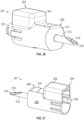
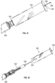
- FIGS. 1-2 are perspective views of a drug delivery safety device.
- FIG. 13 is an interior view from the proximal end of the blunt fill needle cap 202, showing to a distal end of the cap, showing the septum 252 and fill feature 254.
- Fill feature 254 is a rib on an interior surface of the recess 205 of the cap 202. Fill feature 254 interacts with one or more activation latch safety features of the embodiment of FIG. 12 upon assembly to keep it in a fill state.
- FIG. 15 provides a perspective view of a blunt fill needle cap 207 according to an embodiment.
- a proximal end 204 there are one or more clips 203 for engaging with a portion of a needle safety device.
- the cap body 208 has a recess 209 for accommodating an underlying needle safety device in a compressed state having an activation latch.
- a finger hilt 210 At a distal end 206 of the cap 207, there is a finger hilt 210.
- An access protrusion 212 extends from a shoulder of the cap 207.
- a cap cannula 213 extends from a distal end of the access protrusion 212.
- a mini-cap may be provided for the cap cannula 213.
- the cap 207 of this embodiment may be referred to as a blunt needle fill cap.
- FIG. 16 is an interior view from a proximal end of the blunt fill needle cap of FIG. 15 to a distal end of the cap.
- FIG. 16 does not depict a septum but is otherwise analogous to FIG. 13 and in practice a septum is generally present.
- a fill feature 254 in the form of a rib interacts with one or more activation latch safety features of the safety needle device 221 of FIG. 14 upon assembly to keep it in a fill state.
- FIG. 31 is a perspective view of the drug delivery safety device 500 of FIG. 30 in a fill state.
- the cap 502 is twisted to pull back and expose the cannula 536 through an access opening 549 of the cap 502, which locks back (helix cannot be back driven).
- Distal tip 550 of the needle cannula 536 is inserted into a vial.
- FIGS. 35-36 provide an example referred to as a "collet cap.”
- FIG. 35 is a perspective view of a drug delivery safety device 600 comprising a cap 602 and a safety needle device 620.
- a shield face 605 of the cap 602 covers a cannula of safety needle device 620.
- the safety needle device 620 is attached to a syringe 628.
- a second cap is needed.
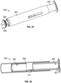
- FIG. 36 is a cross-section view of the cap 602 of FIG. 35 .
- Cap 602 comprises the shield face 605, which comprises an access opening 607.
- a cannula is exposed and free to move through access opening 607 by pulling back on a collet 609, which is effectively the outer diameter (OD) of the cap 602.
Landscapes
- Health & Medical Sciences (AREA)
- Life Sciences & Earth Sciences (AREA)
- Veterinary Medicine (AREA)
- Public Health (AREA)
- General Health & Medical Sciences (AREA)
- Animal Behavior & Ethology (AREA)
- Engineering & Computer Science (AREA)
- Biomedical Technology (AREA)
- Hematology (AREA)
- Heart & Thoracic Surgery (AREA)
- Anesthesiology (AREA)
- Vascular Medicine (AREA)
- Pharmacology & Pharmacy (AREA)
- Environmental & Geological Engineering (AREA)
- Physics & Mathematics (AREA)
- Fluid Mechanics (AREA)
- Diabetes (AREA)
- Biophysics (AREA)
- Pathology (AREA)
- Medical Informatics (AREA)
- Molecular Biology (AREA)
- Surgery (AREA)
- Infusion, Injection, And Reservoir Apparatuses (AREA)
Description
- The present disclosure relates generally to drug delivery safety devices. Specifically, caps for safety needle devices allow for integrated filling and injection.
- Accidental needle sticks with a used needle can transmit disease. Needle assemblies were developed to include needle shields, which are manually telescoped or rotated over a needle cannula after use. This procedure often requires the healthcare worker to hold the syringe barrel in one hand and the shield in the other and assemble the two before risk of needle stick is eliminated. Some safety needle devices offer passive safety features to provide post-injection needle shielding without additional intervention by the user. Passive safety features are activated in many kinds of ways but generally involve a mechanical structure to lock a needle in place or cover it.
- For drug delivery, a syringe is connected to a needle for filling from a fluid supply or fluid holding device, e.g., a vial, and subsequent injection to a patient. A fill state generally of a safety needle device allows for multiple fills, which do not activate the passive safety feature. For some safety needle devices, there is a risk that injection occurs with the device in a fill state, which may result in the passive safety device not activating. After filling, there is an inject state of the safety needle devices in which the passive safety feature will be activated upon completion of the injection.
- There is a need to prevent misuse of safety needle devices. There is also a need for caps for safety needle devices that allow for an integrated device for both filling and injection that do not interfere with passive safety features.
A drug delivery safety device having the features defined within the preamble ofclaim 1 is, for example, known fromUS 2015/094666 ,US 2011/264037 andUS 2007/060904 . - A drug delivery safety device according to the invention is defined by the features of
claim 1. Preferred embodiments are defined by the features of the dependent claims. - Provided are caps for safety needle devices, which allow for an integrated device for both filling and injection that do not interfere with passive safety features. The caps have an access opening that is in fluid communication with a needle cannula. The access opening may comprise an access protrusion extending from a distal end of the cap. Exemplary such caps include, but are not limited to: a spike cap, which includes a spike, typically plastic, as the access protrusion for accessing a fluid supply; and a blunt fill needle cap, which includes a blunt fill cannula, typically metal, secured in the access protrusion. The caps may have a fill feature that engages with a safety feature of the safety needle device to keep it in a fill state.
- Various embodiments are listed below. It will be understood that the embodiments listed below may be combined not only as listed below, but in other suitable combinations in accordance with the scope of the disclosure.
- In an aspect, a drug delivery safety device comprises: a safety needle device comprising a needle hub, a needle cannula, and a safety feature; and a cap comprising a cap body having a proximal end attached to the safety needle device and a distal end having an access opening that is in fluid communication with the needle cannula.
- In another aspect, a safety needle device comprising a needle hub, a needle cannula, and a safety feature; and a cap comprising a cap body having a proximal end attached to the safety needle device, an access opening that is in fluid communication with the needle cannula, and a fill feature that maintains the safety needle device in a fill state.
- Other aspects, not according to the invention, include methods of drug delivery comprises: obtaining any drug delivery safety device disclosed herein; attaching a syringe to the drug delivery safety device; inserting the access protrusion of the cap into a fluid supply; filling the syringe with a fluid; removing the cap; and injecting the fluid into a patient.
-
-
FIG. 1 is a perspective view of a drug delivery safety device. -
FIG. 2 is a perspective view of the drug delivery safety device according toFIG. 1 further including a tip cap; -
FIG. 3 is a perspective view of the drug delivery safety device according toFIG. 1 being used to fill a syringe from a vial; -
FIG. 4 is a cross-section view of the drug delivery safety device according toFIG. 1 assembled with a syringe; -
FIG. 5 provides a close-up perspective view of a proximal end of a safety needle device as included inFIG. 4 ; -
FIG. 6 is an interior view from a proximal end of a spike cap as included inFIG. 1 to a distal end of the cap; -
FIG. 7 illustrates a schematic view of an exemplary fill feature engaged with an exemplary safety feature; -
FIG. 8 provides a perspective view of a blunt fill needle cap according to an embodiment of the invention; -
FIG. 9 provides an exploded perspective view of the blunt fill needle cap ofFIG. 7 ; -
FIG. 10 provides a cross-section view of the blunt fill needle cap ofFIG. 8 ; -
FIG. 11 provides a perspective view of a drug delivery safety device according to an embodiment of the invention; -
FIG. 12 provides a cross-section view of a safety needle device as included inFIG. 11 ; -
FIG. 13 is an interior view from a proximal end of a blunt fill needle cap as included inFIG. 11 to a distal end of the cap; -
FIG. 14 provides a perspective view of a drug delivery safety device according to an embodiment of the invention; -
FIG. 15 is a perspective view of a blunt fill needle cap as included inFIG. 14 ; -
FIG. 16 is an interior view from a proximal end of the blunt fill needle cap ofFIG. 15 to a distal end of the cap; -
FIG. 17 provides a perspective view of a drug delivery safety device according to an embodiment; -
FIG. 18 is a perspective view of a spike cap as included inFIG. 17 ; -
FIG. 19 is an interior view from a proximal end of the spike cap ofFIG. 18 to a distal end of the cap; -
FIG. 20 provides a perspective view of a drug delivery safety device according to an embodiment; -
FIG. 21 is a perspective view of a spike cap as included inFIG. 20 ; -
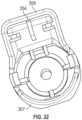
FIG. 22 is an interior view from a proximal end of the spike cap ofFIG. 21 to a distal end of the cap; -
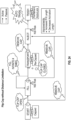
FIG. 23 is a general flow chart depicting "3 Choice" Passive Safety Device Functional Architecture; -
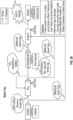
FIG. 24 is a flow chart depicting "3 Choice" for an embodiment; -
FIG. 25 is a flow chart depicting "3 Choice" for an embodiment; -
FIG. 26 is a flow chart depicting "3 Choice" for an embodiment; -
FIG. 27 is a perspective view of a drug delivery safety device before engaging with a vial; -
FIG. 28 is a perspective view of the drug delivery safety device ofFIG. 27 after fill from a vial; -
FIG. 29 is a perspective view of the drug delivery safety device ofFIG. 27 after removal of the cap from safety needle device; -
FIG. 30 is a perspective view of a drug delivery safety device; -
FIG. 31 is a perspective view of the drug delivery safety device ofFIG. 30 in a fill state; -
FIG. 32 is a perspective view of the drug delivery safety device ofFIG. 30 after removal of the cap from safety needle device; -
FIG. 33 is a perspective view of a drug delivery safety device in a fill state; -
FIG. 34 is a perspective view of a drug delivery safety device in a fill state; -
FIG. 35 is a perspective view of a cap; -
FIG. 36 is a cross-section view of the cap ofFIG. 35 ; -
FIG. 37 is a perspective view of a drug delivery safety device in a fill state engaged with a vial; and -
FIG. 38 is a cross-section of an exemplary safety needle device. - Before describing several exemplary embodiments, it is to be understood that the disclosure is not limited to the details of construction or process steps set forth in the following description. The disclosure is capable of other embodiments and of being practiced or being carried out in various ways falling under the scope of the appended claims.
- Caps for safety needle devices are configured for removable attachment to the safety needle devices. The caps allow for an integrated drug delivery safety device for both filling and injecting. A safety needle device has one or more safety features, which may be referred to as a passive lockout safety. The caps allow for keeping the safety needle devices in a fill state. Upon removal of the caps, the safety needle devices are in an injection state. Assemblies herein facilitate "3 Choice" Passive Safety Device Functional Architecture which allows a user to Fill and Inject with the same device. Mis-use by injection when the safety needle is in its fill state is also minimized and/or avoided. The device in fill state is intended to prevent the user from injecting a patient, for example it would be very difficult, painful, and against convention to use a blunt fill, plastic spike, or vial access device to deliver to a patient. The caps disclosed here may restrain the passive lockout safety, which is permissible because while they do this they add these other impediments to injection. With specific regard to spike caps and blunt needle fill caps, users are not limited in accessing vials including those of varying depths.
- Caps comprises a cap body having a proximal end attached to a safety needle device and an access opening that is in fluid communication with a needle cannula of the safety needle device. The access opening may comprise an access protrusion extending from a distal end of the cap. Caps having access protrusions include spike caps and blunt fill needle caps. The access protrusions may have a vent lumen to allow for pressure equalization in the vial (allows for large and or withdrawals without a pre-air bolus withdrawals). The vent lumen may have a filter to prevent vial contamination.
- A spike cap includes a spike, typically plastic. The spike may be designed to include internal features, straws, and/or faces to facilitate manufacture and fill, minimize drug hold-up, and to protect the needle cannula of the safety needle device. A blunt fill needle cap, which includes a blunt fill cannula, typically metal, secured in the access protrusion. The blunt fill cannula may be blunt and metal, a single bevel, a pencil tip with side port, fully sharp, or any desired tip geometry.
- Caps may be fabricated from suitable medical grade materials including polymers or metals. Preferably the caps are injection-molded using a thermoplastic and/or thermoplastic elastomer (TPE). Septums for inside the cap may be fabricated from a suitable elastomer. Finger grips for an outside surface of the cap can be formed from the same elastomer as the septum. Caps may be fabricated as a "two shot" molded part.
- Caps may have fill features to keep them in a fill state. The fill features are a characteristic of the cap including a dimension or a structure. A dimension of the cap, e.g., its length, may allow no restrictions on needle penetration thereby keeping the needle device in a fill state. As a non-limiting first example, an initial length of a needle cannula of the underlying safety needle device is enough to penetrate the septum of the cap and allow fluid to flow. A second non-limiting example is that a sleeve of the underlying device is compressed to a length when the cap is on that is less than the activation distance. A structure of the cap may engage with a safety feature of the safety needle device. A structure of the cap may be on its inside surface, designed to contacts a safety feature of the safety needle device. Such structures may protrude from the inside surface, comprising, for example, ribs, ledges, posts, lugs, angled cams, and the like; and/or the structures may be below the inside surface, including, but not being limited to, grooves, channels, tracks, and the like; and/or the structures may be additional components contained in the cap body such as tubes. Spike caps and blunt fill needle caps optionally have fill features, depending on the underlying safety needle device.
- The cap engages with a portion of the safety needle device by methods including but not limited to: snap-fit, rotatably-fit, press-fit. The cap may be removed by pulling, quarter turning, or squeezing to disengage. For an embodiment for squeezing to disengage, a latch on the cap may be present that requires only non-axial force.
- According to the invention, the safety feature is an activation latch, found for example in a stored energy latch safety needle device or in a front end trigger safety needle device, and the fill feature is a rib that keeps the safety feature disengaged.
- In one or more examples, not according to the invention, the safety feature is a clip, found for example in a linear distance trigger safety needle device, and the fill feature is a tube or a rib or a ledge that keeps arms of the clip open.
- In one or more examples, not according to the invention, the safety feature is a guide element of a housing body, found for example in a tube-in-tube safety needle device, and the fill feature is the dimension of the cap which allows for multiple fills without activating the safety device.
- Any suitable needle devices comprising a safety feature may be used in conjunction with the caps disclosed herein. Exemplary safety needle devices include, but are not limited to, those described in commonly owned, co-filed internal reference numbers P-15379@ (tube-in-tube), P-15380@ (stored energy latch), and P-15385@ (collapsible housings, which include rotating force trigger, linear distance trigger, and front end trigger). Types of safety features vary in structure and mechanics but in general, safety needle devices have a fill state and an inject state.
- To start, a product comes packaged in a safe state in which the needle is covered and prevents needle stick injury (NSI). This can be in the form of a hard-pack or in a blister with a separate cap. At this point the user makes the first choice - Fill (access a vial to fill a syringe or transfer fluids) or Inject (insert the needle into a patient to deliver medication) - and they actively change the device to that state. Assuming the user chooses to Fill, once they complete filling, they now make the second choice, do I fill again (perform another vial access), move the product to an inject state, or more the product to a transport state. Note that each of these choices requires an active motion by the user. Assuming the user chooses to move the product to the transport state, they now placing it into a safe state that could prevent NSI's. Following transportation, the user then needs to make the third choice - actively change the product to then inject state. Once in the inject state, within approximately the first 5mm or less of the needle penetrating the patient's skin (or other medium) the device will automatically lock out - thereby defining passive safety.
- Whenever the device is in a "fill state" it is in a state that allows for potential needle stick injury and when the needle enters into a vial (or other medium) and then exits, it does not lock. This means that a user could access a vial to fill an infinite number of times. Similarly, whenever the device is in an "inject state" it is in a state that also allows for potential needle stick injury. However, once the needle enters into a patient (or other medium) then then exits it automatically locks after 1 time.
- A user can move the Inject State at any point in the process. This means that the user can go from state to inject, fill to inject, or transport to inject as indicated above. In order to change states in a 3 Choice functional architecture, a combination of cap and safety needle device may be used including but not limited to the following embodiments.
- Flip Cap - A flip cap could be used to change states between Start, Fill, Transport, and Inject. The flip cap would start closed, could be flipped open to fill, could be flipped closed to transport, and could be removed prior to injection to achieve the injection state. However, unlike devices that limit the distance that the needle can penetrate the vial in order to prevent passive safety device activation, the flip cap herein does not require limiting the distance of needle penetration. This solves the problem associated with devices that limit needle penetration distance and the trade-off regarding penetration depth in the fill state and the inject state. For example, in a device that limits needle penetration, a user may only have approximately 15 mm or less needle length to access the vial and similarly the device does not lock out in the patient skin until a depth of 15 mm or greater is achieved. With the flip cap disclosed herein, when the cap is on the full needle length can be used without locking out and when the cap is off the needle locks out almost immediately after entry in to the patient's skin (approximately 5 mm or less). Mechanisms that can use this flip cap include stored energy latch, rotating force trigger, linear distance trigger, and front end trigger.
- Double Caps - A double cap can be used to change states between start, fill, transport, and inject. To start the product comes with both caps on. To fill remove the first "mini-cap." To transport, re-attach the "mini-cap." To inject, remove the "large-cap" contains the "mini-cap." (Note: The large cap can also be removed however on its own once fill is completed if a user wants to go directly from fill to inject.) Like with the flip cap above the double cap does not work on limiting distance. Therefore, the full needle can be used for filling if desired and the once the caps are both removed, lock out occurs almost immediately after the needle enters the patient's skin (approximately 5 mm or less). Mechanisms developed today that can use this double cap include stored energy latch, rotating force trigger, linear distance trigger, and front end trigger.
- Alternate Caps - Other Alternate caps also are suitable for 3 Choice. These include the Clothes Pin Cap, Twist Cap, Basket Cap with Flex Arms, Spikey Cap, Collet Cap, and Cap with Grip Arms as shown in
FIGS. 27-37 discussed below. Alternate caps can work with stored energy latch, rotating force trigger, linear distance trigger, and front end trigger. - Spike Cap or Blunt Fill Needle Cap- Like the double cap, the spike cap or blunt fill needle cap could come packaged with or without a "mini-cap." (If no "mini-cap" then cap removal and re-capping would not be required.) A spike cap or blunt fill needle cap packaged with a mini-cap, would involve removing the mini-cap to fill, replacing the mini-cap to transport, and remove the spike cap or blunt fill needle cap to inject. However, unlike the double cap the spike cap and blunt fill needle cap would have the added benefits of (1) protecting the needle tip used from injection from dulling and (2) deterring a user from injecting with the device in a fill state as clinicians are highly unlikely to try to inject a patient with a plastic molded spike or a or blunt fill needle. This also helps to drive compliance with using the device correctly and makes it more intuitive to learn.
- Turning to the figures,
FIGS. 1-2 are perspective views of a drug delivery safety device. -
Drug delivery device 100 comprises acap 102 and asafety needle device 120. Thecap 102 removably attaches to a portion of thesafety needle device 120 at aproximal end 104 of thecap 102. Thecap 102 engages with a portion of thesafety needle device 120 by methods including but not limited to: snap-fit, rotatably-fit, press-fit. The cap may be removed by pulling, quarter turning, or squeezing to release. - At a
distal end 106 of thecap 102, there is afinger hilt 110, which also provides a grip area. Anaccess protrusion 112 extends from ashoulder 114 of thecap 102. Theshoulder 114 acts as a spike stop against a vial. There is abeveled tip 116 having anopening 118 at the end of theaccess protrusion 112. The drugdelivery safety device 100 may further include atip cap 124 as shown inFIG. 2 . Thetip cap 124 may snap-fit, rotatably-fit, or press-fit to thedistal end 106 of thecap 102. Thecap 102 of this embodiment may be referred to as a spike cap. -
FIG. 3 shows thebeveled tip 116 of thespike cap 102 upon insertion into avial 126. Asyringe 128 is attached to a needle hub of thesafety needle device 120 is filled with fluid from thevial 126. Low force (e.g., 0 lbs) is needed to push vial off of the spike cap. - An exemplary safety needle device is referred to herein as a "rotating force trigger," which is shown in cross-section in combination with a syringe and spike cap in
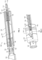
FIG. 4 . A close-up perspective view of a proximal end of the "rotating force trigger" is shown inFIG. 5 . The "rotating force trigger" embodiment contains one or more safety features in the form of its rotating cam, lock clip, and/or device cap. InFIGS. 4-5 , the rotating force trigger drugdelivery safety device 120 comprises aneedle hub 122 for attachment of the drugdelivery safety device 120 to asyringe 128;needle hub 122 has an attachedneedle cannula 136. Adevice body 130, which engagesneedle hub 122, encloses arotating cam 138.Rotating cam 138 engagesbody 130 through aslot 140 in asidewall 131 ofbody 130. As shown in more detail inFIG. 5 ,slot 140 comprises three segments: a proximalangled lead ramp 142, aledge 144 at the distal end of the angled lead ramp for seating the rotating cam, and anaxial slot portion 146 distal to the ledge. -
Needle cannula 136 is surrounded by aflexible housing 134 which connectsrotating cam 138 to a lock clip (not shown) near the distal end ofneedle cannula 136 such thatneedle cannula 136 is substantially covered by the flexible housing but adistal tip 150 of theneedle cannula 136 is exposed. The passive shielding system includes a trigger mechanism comprising afirst spring 132 which connectsrotating cam 138 to the lock clip and a second spring (not shown) inbody 130 extending from rotatingcam 138 proximally towardneedle hub 122.First spring 132 biases lock clip distally and second springbiases rotating cam 138 distally. The lock clip may be housed in adevice cap 148 which is attached toflexible housing 134. - The
distal tip 150 of theneedle cannula 136 goes through aseptum 152 upon entering a channel of theaccess protrusion 112.Septum 152 is located at the distal end of thecap 102. Its proximity to the tip of the access protrusion 112 (e.g., plastic spike) allows for theseptum 152 to be only penetrated at the time of use, by pulling thecap 102 proximally toward thehub 122. This may improve sealing of the septum and allow for less elastomer to be used. Also this septum location may allow for less residual drug holdup in the device. -
FIG. 6 is an interior view from the proximal end of thespike cap 102 to a distal end of the cap, showing theseptum 152 and fillfeature 154.Fill feature 154 is a rib on an interior surface of thecap 102.Fill feature 154 interacts with therotating cam 138 safety feature of the "rotating force trigger" embodiment upon assembly by residing in theslot 140 to keep it in a fill state. Anoptional lumen vent 151 allows for pressure equalization in the vial (allows for large and or withdrawals without a pre-air bolus withdrawals).FIG. 7 illustrates thesyringe 128 assembled with a slotted safety needle device where fill feature 154 (e.g., a rib) ofspike cap 102 resides inslot 140 ofbody 130. -
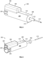
FIG. 8 provides a perspective view of a bluntfill needle cap 202 according to the invention. At aproximal end 204, there are one ormore clips 203 for engaging with a portion of a needle safety device. Thecap body 208 has arecess 205 for accommodating an underlying needle safety device having an activation latch. At adistal end 206 of thecap 202, there is afinger hilt 210. Anaccess protrusion 212 extends from ashoulder 214 of thecap 202. Acap cannula 213 extends from a distal end of theaccess protrusion 212. A mini-cap may be provided for thecap cannula 213. Thecap 202 of this embodiment may be referred to as a blunt needle fill cap. -
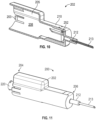
FIG. 9 provides an exploded perspective view of the bluntfill needle cap 202 ofFIG. 8 comprising thecap body 208, which has therecess 205 andclips 203, aseptum 252, and thecap cannula 213.FIG. 10 provides a cross-section view of the bluntfill needle cap 202 ofFIG. 8 as assembled: comprising thecap body 208, which has therecess 205 andclip 203, aseptum 252, which resides in thedistal end 206 of thecap 202, and thecap cannula 213, which resides in theaccess protrusion 212. A seal may be provided between thecap cannula 213 and a surface of theaccess protrusion 212. - The caps disclosed herein are suitable for many different kinds of safety needle devices.
FIG. 38 illustrates a cross-section of an exemplary tube-in-tubesafety needle device 10 in a fill state. The safety features are guide elements (e.g., first, second, and third guide paths) for this exemplary safety needle device. The device has ahousing body 23, and anopening 24 located on the distal end. Afirst guide path 30, asecond guide path 32 and athird guide path 34 are disposed on thehousing body 23. First guidepath 30 andthird guide path 34 are generally parallel to a central axis which extends along thehousing body 23.Second guide path 32 is positioned at an angle, curvature or taper relative to the axis and intersects thefirst guide path 30 andthird guide path 34 thereby serving to separate thefirst guide path 30 andthird guide path 34.Second guide path 32 permits theguide element 52 to shift between thefirst guide path 30 andthird guide path 34. In one or more embodiment, thefirst guide path 30, thesecond guide path 32 and thethird guide path 34 are disposed on the inner diameter of thehousing body 23 to prevent tampering. In one or more embodiment, thefirst guide path 30, thesecond guide path 32 and thethird guide path 34 are disposed on the inner diameter of thehousing body 23 so as not to obstruct needle cannula/needle tip visibility. A cap as disclosed herein is of a dimension that keeps the device in a fill state. -
FIG. 11 provides a perspective view of a drug delivery safety device according to the invention.Drug delivery device 200 comprises thecap 202 according toFIGS. 8-10 and13 and asafety needle device 220, which has an activation latch ("stored energy latch") and is in an expanded configuration. Thecap 202 removably attaches to a portion of thesafety needle device 220 at aproximal end 204 of thecap 202.Cap cannula 213 resides inaccess protrusion 212 at adistal end 206 of thecap 202. Thecap 202 may snap-fit, rotatably-fit, or press-fit to a portion of thesafety needle device 220. -
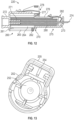
FIG. 12 provides a cross-section view of a safety needle device as included inFIG. 11 , which includes an activation latch.Safety needle device 220 includes ahousing 260 configured to couple to a syringe (not shown), which has aproximal end 261, adistal end 262, ahousing body 263 and anopening 264 located on thedistal end 262. Tether 270 is disposed on thehousing body 263. Tether 270 is generally parallel to a central axis which extends along thehousing body 263. -
Needle hub 272 is disposed on theproximal end 261 of thehousing 260.Needle cannula 273 is attached to theneedle hub 272. Aneedle support 271 extends from theneedle hub 272 to support theneedle cannula 273.Distal end 262 ofhousing 260 couples to aretractable sheath 275 such that theretractable sheath 275 is configured to move along a central axis inhousing body 263. A channel and an aperture are included in theretractable sheath 275 in order to permit theneedle cannula 273 anddistal tip 274 ofneedle cannula 273 to pass therethrough. - A
proximal end 276 of theretractable sheath 275 includes aretention hook 277 that extends radially outward from theproximal end 276 ofretractable sheath 275 and is configured to engage anactivation latch 278 of thehousing body 263.Housing 260 has an opening that receives theretractable sheath 275. Theretractable sheath 275 is spring loaded.Activation latch 278 and thespring element 280 hold stored energy. Upon beginning injection, the energy in theactivation latch 278 is released once theretention hook 277 on theproximal end 276 of theretractable sheath 275 is released from engagement with theactivation latch 278 upon a practitioner depressing the activation latch over a very short distance. Alockout latch 282 is able to clip over thedistal tip 274 of theneedle cannula 273 upon injection thereby passively locking out the safety needle device and preventing needle stick injury to the practitioner. Safety features of this safety needle device include but are not limited to theactivation latch 278 and/or thelockout latch 282. -
FIG. 13 is an interior view from the proximal end of the bluntfill needle cap 202, showing to a distal end of the cap, showing theseptum 252 and fillfeature 254.Fill feature 254 is a rib on an interior surface of therecess 205 of thecap 202.Fill feature 254 interacts with one or more activation latch safety features of the embodiment ofFIG. 12 upon assembly to keep it in a fill state. -
FIG. 14 provides a perspective view of a drug delivery safety device according to an embodiment.FIG. 14 is analogous toFIG. 11 in terms of having a blunt fill needle cap in combination with a stored energy latch safety needle device. The stored energy latch safety needle device ofFIG. 14 is provided in a compressed configuration. The blunt fill needle cap ofFIGS. 14 and 15 are thereby shorter than those ofFIGS. 11 and8 , respectively, but is analogous otherwise.Drug delivery device 201 comprises acap 207 and asafety needle device 221, which has an activation latch ("stored energy latch") and is in a compressed configuration. Thecap 207 removably attaches to a portion of thesafety needle device 221 at aproximal end 204 of thecap 207.Cap cannula 213 resides inaccess protrusion 212 at adistal end 206 of thecap 202. Thecap 207 may snap-fit, rotatably-fit, or press-fit to a portion of thesafety needle device 221. -
FIG. 15 provides a perspective view of a bluntfill needle cap 207 according to an embodiment. At aproximal end 204, there are one ormore clips 203 for engaging with a portion of a needle safety device. Thecap body 208 has arecess 209 for accommodating an underlying needle safety device in a compressed state having an activation latch. At adistal end 206 of thecap 207, there is afinger hilt 210. Anaccess protrusion 212 extends from a shoulder of thecap 207. Acap cannula 213 extends from a distal end of theaccess protrusion 212. A mini-cap may be provided for thecap cannula 213. Thecap 207 of this embodiment may be referred to as a blunt needle fill cap. -
FIG. 16 is an interior view from a proximal end of the blunt fill needle cap ofFIG. 15 to a distal end of the cap.FIG. 16 does not depict a septum but is otherwise analogous toFIG. 13 and in practice a septum is generally present. Afill feature 254 in the form of a rib interacts with one or more activation latch safety features of thesafety needle device 221 ofFIG. 14 upon assembly to keep it in a fill state. -
FIG. 17 provides a perspective view of a drug delivery safety device according to an embodiment.FIG. 17 is analogous toFIG. 11 in terms of using a stored energy latch safety needle device in an expanded configuration. InFIG. 17 , the cap is a spike cap, analogous to that ofFIG. 1 for a different safety needle device. The spike cap ofFIGS. 17 and18 thereby have an addition of a recess to accommodate the activation latch.Drug delivery device 300 ofFIG. 17 comprisescap 302 and asafety needle device 320, which has an activation latch ("stored energy latch") and is in an expanded configuration. Thecap 302 removably attaches to a portion of thesafety needle device 320 at aproximal end 304 of thecap 302.Shoulder 314 acts as a spike stop against a vial. There is abeveled tip 316 having anopening 318 at the end of theaccess protrusion 312, which is located at adistal end 306 of thecap 302. Thecap 302 may snap-fit, rotatably-fit, or press-fit to a portion of thesafety needle device 320. -
FIG. 18 provides a perspective view of thespike cap 302 according to an embodiment. At aproximal end 304, there are one ormore clips 303 for engaging with a portion of a needle safety device. Thecap body 308 has arecess 305 for accommodating an underlying needle safety device having an activation latch. At adistal end 306 of thecap 302, there is afinger hilt 310. Theshoulder 314 acts as a spike stop against a vial. Thebeveled tip 316 has theopening 318 at the end of theaccess protrusion 312, which is located at thedistal end 306 of thecap 302. A mini-cap may be provided for thebeveled tip 316. Thecap 302 of this embodiment may be referred to as spike cap. -
FIG. 19 is an interior view from a proximal end of the spike cap ofFIG. 18 to a distal end of the cap.FIG. 19 does not show a septum but is otherwise analogous toFIG. 13 and in practice a septum is generally present. Afill feature 354 in the form of a rib interacts with one or more the activation latch safety features of thesafety needle device 320 ofFIG. 17 upon assembly to keep it in a fill state. -
FIG. 20 provides a perspective view of a drug delivery safety device according to an embodiment.FIG. 20 is analogous toFIG. 14 in terms of using a stored energy latch safety needle device in a compressed state.FIGS. 20-21 include a spike cap analogous to that ofFIG. 18 but is shorter in length.Drug delivery device 301 ofFIG. 20 comprises acap 307 and asafety needle device 321, which has an activation latch ("stored energy latch") and is in a compressed configuration. Thecap 307 removably attaches to a portion of thesafety needle device 321 at aproximal end 304 of thecap 307.Shoulder 314 acts as a spike stop against a vial. There is abeveled tip 316 having anopening 318 at the end of theaccess protrusion 312, which is located at adistal end 306 of thecap 307. Thecap 307 may snap-fit, rotatably-fit, or press-fit to a portion of thesafety needle device 321. -
FIG. 21 provides a perspective view of thespike cap 307 according to an embodiment. At aproximal end 304, there are one ormore clips 303 for engaging with a portion of a needle safety device. Thecap body 308 has arecess 309 for accommodating an underlying needle safety device having an activation latch. At adistal end 306 of thecap 307, there is afinger hilt 310. Thebeveled tip 316 has theopening 318 at the end of theaccess protrusion 312, which is located at thedistal end 306 of thecap 307. A mini-cap may be provided for thebeveled tip 316. Thecap 307 of this embodiment may be referred to as spike cap. -
FIG. 22 is an interior view from a proximal end of the spike cap ofFIG. 21 to a distal end of the cap.FIG. 22 does not show a septum but is otherwise analogous toFIG. 13 and in practice a septum is generally present. Afill feature 354 in the form of a rib interacts with one or more activation latch safety features of thesafety needle device 321 ofFIG. 20 upon assembly to keep it in a fill state. -
FIG. 23 is a general flow chart depicting "3 Choice" Passive Safety Device Functional Architecture.FIG. 24 is a flow chart depicting "3 Choice" for an embodiment of using a flip cap without distance limitation.FIG. 25 is a flow chart depicting "3 Choice" for an embodiment of using double caps.FIG. 26 is a flow chart depicting "3 Choice" for an embodiment of using spike caps or blunt fill needle caps. -
FIGS. 27-29 provide an example referred to as a "clothes pin cap". This example includes an internal rib to prevent safety locking during fill. No second cap is needed for 3 Choice Architecture.FIG. 27 is a perspective view of a drugdelivery safety device 400 before engaging with avial 426 offluid 425. InFIG. 27 , thecap 402 andsafety needle device 420 are locked in start position. A cannula ofsafety needle device 420 is recessed in thecap 402 inFIG. 27 . Asyringe 428 is attached to a needle hub of thesafety needle device 420, which is filled withfluid 425 from thevial 426. Low force (e.g., 0 lbs) is needed to push a vial off of thecap 402, which does not have an access protrusion and beveled tip of a spike cap; nor does it have an access protrusion and cap cannula of a blunt needle fill cap.FIG. 28 is a perspective view of the drugdelivery safety device 400 ofFIG. 27 after fill from a vial. To begin fill, thecap 402 is squeezed to pull it back and expose thecannula 436 through an access opening (not shown) of thecap 402, which may lock back or spring back.Distal tip 450 of theneedle cannula 436 is inserted intovial 426. Thecap 402 may be squeezed to pull off for injection, or rest back to start for transport, or can go straight to inject as well. Can have two discrete lock points, start-safe, retracted-inject, or act as a ratchet, such that thecap 402 can be moved axially while squeezed but locks when released.FIG. 29 is a perspective view of the drugdelivery safety device 400 ofFIG. 27 after removal of thecap 402 fromsafety needle device 420. -
FIGS. 30-32 provide an example referred to as a "twist cap". An internal helix rib prevents safety locking during fill. No second cap is needed for 3 Choice Architecture.FIG. 30 is a perspective view of a drugdelivery safety device 500 before engaging with a vial, wherecap 502 andsafety needle device 520 are locked in a start position. A cannula ofsafety needle device 420 is recessed in thecap 402 inFIG. 29 . Asyringe 528 is attached to a needle hub 422 of thesafety needle device 520. Low force (e.g., 0 lbs) is needed to push a vial off of thecap 502, which does not have an access protrusion and beveled tip of a spike cap; nor does it have an access protrusion and cap cannula of a blunt needle fill cap.FIG. 31 is a perspective view of the drugdelivery safety device 500 ofFIG. 30 in a fill state. To begin fill, thecap 502 is twisted to pull back and expose thecannula 536 through an access opening 549 of thecap 502, which locks back (helix cannot be back driven).Distal tip 550 of theneedle cannula 536 is inserted into a vial. Thecap 502 may twist off for inject, or reset back to start (detented) for transport, can go straight to inject as well. No compound motion is needed as in the above clothspin cap. Only a twist is needed to change cap state. The cap helix can have sufficient pitch to prevent axial back-driving, this prevents bumps to the cap from exposing the sharp.FIG. 32 is a perspective view of the drugdelivery safety device 500 ofFIG. 30 including access opening 549 after removal of thecap 502 fromsafety needle device 420 includingcannula 536 anddistal top 550. -
FIG. 33 provides a drugdelivery safety device 560 comprising acap 562 referred to as a "basket cap with flex arms," which is attached to asafety needle device 564, which is attached to asyringe 568. This example includes an internal rib to prevent safety locking during fill. A second cap is needed.Cannula 567 of thesafety needle device 564 is exposed for insertion intovial 569. Thecannula 567 of thesafety needle device 564 passes though through an access opening (not shown) of thecap 562.Arms 566 reduce chance of inject in fill state becausearms 566 will contact skin of a patient.Arms 566 flex open forvial 569 however. -
FIG. 34 provides a drugdelivery safety device 570 comprising acap 572 referred to as a "spikey cap," which is attached to asafety needle device 574, which is attached to asyringe 578. This example includes an internal rib to prevent safety locking during fill. A second cap is needed.Cannula 577 of thesafety needle device 574 passes though through an access opening 575 of thecap 572 for insertion intovial 579. A plurality ofspikes 576 reduce chance of inject in fill state.Spikes 577 will contact skin of a patient and cause negative feedback, but act as stabilizer for rubber stopper. The visual appearance of the spikes may prevent the user from contacting a patient's skin. -
FIGS. 35-36 provide an example referred to as a "collet cap."FIG. 35 is a perspective view of a drugdelivery safety device 600 comprising acap 602 and asafety needle device 620. Ashield face 605 of thecap 602 covers a cannula ofsafety needle device 620. Thesafety needle device 620 is attached to asyringe 628. A second cap is needed.FIG. 36 is a cross-section view of thecap 602 ofFIG. 35 .Cap 602 comprises theshield face 605, which comprises anaccess opening 607. A cannula is exposed and free to move through access opening 607 by pulling back on acollet 609, which is effectively the outer diameter (OD) of thecap 602. Motion ofcollet 609 against a device body 630 (ofsafety needle device 620 ofFIG. 34 ) flexes lockarms 611 open. Bumping the distal end of thecap 602 does not retract thecap 602, only pulling on thecollet 609 does, this prevents unintended needle exposure. -
FIG. 37 provides a drugdelivery safety device 580 comprising acap 582 referred to as a "cap with grip arms," which is attached to asafety needle device 584, which is attached to asyringe 588. A second cap is needed. A cannula of thesafety needle device 584 passes though through an access opening (not shown) of thecap 582.Grip arms 586 reduce chance of inject in fill state becausearms 586 will contact skin of a patient.Grip arms 586 flex open forvial 589 however and grip a neck of thevial 589 for stability. - Reference throughout this specification to "one embodiment," "certain embodiments," "one or more embodiments" or "an embodiment" means that a particular feature, structure, material, or characteristic described in connection with the embodiment is included in at least one embodiment of the disclosure. Thus, the appearances of the phrases such as "in one or more embodiments," "in certain embodiments," "in one embodiment" or "in an embodiment" in various places throughout this specification are not necessarily referring to the same embodiment of the disclosure. Furthermore, the particular features, structures, materials, or characteristics may be combined in any suitable manner in one or more embodiments.
- Although the disclosure herein has been described with reference to particular embodiments, it is to be understood that these embodiments are merely illustrative of the principles and applications of the present disclosure. It will be apparent to those skilled in the art that various modifications and variations can be made to the apparatus of the present disclosure without departing from the scope of the disclosure. Thus, it is intended that the present disclosure include modifications and variations that are within the scope of the appended claims and their equivalents.
Claims (15)
- A drug delivery safety device (200, 201) comprisinga safety needle device (220, 221) comprising a housing body (263) configured to couple to a syringe, the housing body (263) having a proximal end (261) and a distal end (262), the distal end (262) coupled to a retractable sheath (275), an opening (264) located on the distal end (262) which receives the retractable sheath (275), the sheath (275) being movable along a central axis of the housing body (263), a needle hub (272) is disposed on the proximal end (261), a needle cannula (273) is attached to the needle hub (272), a needle support (271) extending from the needle hub (272) to support the needle cannula (273); and a lockout latch (282) able to clip over the distal tip (274) of the needle cannula (273) upon injection to passively lock out the safety device (220),characterized in that:the safety needle device (220) having a proximal end (276) of the retractable sheath (275) includes a retention hook (277) that extends radially outward from the proximal end (276) of retractable sheath (275) and is configured to engage an activation latch (278) of the housing body (263), the retractable sheath (275) being spring loaded, the retention hook (277) is released from the activation latch (278) by depressing the activation latch (277) upon injection;a cap (202, 207) comprising a cap body (208) having a proximal end (204) removably attached to the safety needle device (220), a distal end (206) having an access protrusion (212) that is in fluid communication with the needle cannula (273), a cap cannula (213) extends from a distal end of the access protrusion (212); a recess (205) for accommodating the safety needly device having the activation latch (278); a finger hilt (210) at a distal end (206) of the cap; and a septum (252) which resides in the distal end (206) of the cap (202, 207);wherein an inside surface of the cap (202, 207) further comprises a fill feature (254) engageable with the safety needle device (220) for maintaining a fill state of the safety needle device (220), the fill feature includes a rib (254) on an interior surface of a recess (205) of the cap (202, 207) which interacts with one or more activation latch safety features upon assembly to keep it in a fill state.
- The drug delivery safety device of claim 1, wherein the fill feature (254) comprises a rib located on the inside surface of the cap body in contact with the activation latch (278) of the safety needle device (220).
- The drug delivery safety device of one of claims 1 or 2, wherein the cap (202, 207) snap-fits to the safety needle device (220).
- The drug delivery safety device of one of claims 1 to 3, wherein the cap (202, 207) rotatably-fits to the safety needle device (220).
- The drug delivery safety device of one of claims 1 to 4, wherein the cap (202, 207) press-fits to the safety needle device (220).
- The drug delivery safety device of one of claims 1 to 5, wherein the proximal end (204) of the cap (202, 207) is attached to the needle hub (272) of the safety needle device (220).
- The drug delivery safety device of one of claims 1 to 6, wherein the cap (202, 207) further comprises a septum (252) inside the cap body (208) at the distal end (206) adjacent to the protrusion (212).
- The drug delivery safety device of one of claims 1 to 7, wherein the cap (202, 207) further comprises a finger hilt (210).
- The drug delivery safety device of one of claims 2 to 8, wherein the cap (202, 207) further comprises a shoulder at the distal end (206) of the cap body (202) from which the access protrusion (212) extends.
- The drug delivery safety device of one of claims 1 to 9, wherein the access protrusion (212) comprises a beveled tip (316).
- The drug delivery safety device of one of claims 1 to 10, wherein the cap (202, 207) further comprises a blunt fill cannula extending from a distal end of the access protrusion (212) and in fluid communication with the needle cannula (273) and a seal between the blunt fill cannula and an inside surface of the access protrusion (212).
- The drug delivery safety device of claim 11 further comprising a tip cap (124) that covers a tip of the blunt fill cannula.
- The drug delivery safety device of claim 1, wherein the cap cannula (213) of the safety needle device (220) resides within the access protrusion (212) at the distal end (206) of the cap (202, 207).
- The drug delivery safety device of claim 1, further comprising one or more clips (203) at a proximal end (204).
- The drug delivery safety device of claim 1, wherein the cap body (208) includes a recess (209).
Applications Claiming Priority (3)
| Application Number | Priority Date | Filing Date | Title |
|---|---|---|---|
| US201662433526P | 2016-12-13 | 2016-12-13 | |
| US15/838,461 US10918801B2 (en) | 2016-12-13 | 2017-12-12 | Caps for integrated fill and inject of safety needle devices |
| PCT/US2017/065956 WO2018111961A1 (en) | 2016-12-13 | 2017-12-13 | Caps for integrated fill and inject of safety needle devices |
Publications (3)
| Publication Number | Publication Date |
|---|---|
| EP3554450A1 EP3554450A1 (en) | 2019-10-23 |
| EP3554450B1 true EP3554450B1 (en) | 2024-06-12 |
| EP3554450C0 EP3554450C0 (en) | 2024-06-12 |
Family
ID=62488115
Family Applications (1)
| Application Number | Title | Priority Date | Filing Date |
|---|---|---|---|
| EP17822965.4A Active EP3554450B1 (en) | 2016-12-13 | 2017-12-13 | Caps for integrated fill and inject of safety needle devices |
Country Status (7)
| Country | Link |
|---|---|
| US (1) | US10918801B2 (en) |
| EP (1) | EP3554450B1 (en) |
| JP (2) | JP7090084B2 (en) |
| CN (2) | CN115192448B (en) |
| AU (3) | AU2017376144B2 (en) |
| CA (1) | CA3044548C (en) |
| WO (1) | WO2018111961A1 (en) |
Families Citing this family (10)
| Publication number | Priority date | Publication date | Assignee | Title |
|---|---|---|---|---|
| US11058444B2 (en) | 2017-12-11 | 2021-07-13 | Covidien Lp | Electrically enhanced retrieval of material from vessel lumens |
| US11974752B2 (en) | 2019-12-12 | 2024-05-07 | Covidien Lp | Electrically enhanced retrieval of material from vessel lumens |
| US12318126B2 (en) | 2021-06-25 | 2025-06-03 | Covidien Lp | Current generator for a medical treatment system |
| WO2019140067A1 (en) * | 2018-01-10 | 2019-07-18 | LynJohnston, LLC | Compact injector systems and methods |
| US11160571B2 (en) | 2018-06-22 | 2021-11-02 | Covidien Lp | Electrically enhanced retrieval of material from vessel lumens |
| US11612430B2 (en) | 2019-03-19 | 2023-03-28 | Covidien Lp | Electrically enhanced retrieval of material from vessel lumens |
| US11523838B2 (en) | 2019-06-12 | 2022-12-13 | Covidien Lp | Retrieval of material from corporeal lumens |
| US11395668B2 (en) | 2019-12-12 | 2022-07-26 | Covidien Lp | Electrically enhanced retrieval of material from vessel lumens |
| BR112022017689A2 (en) * | 2020-03-05 | 2022-10-18 | Becton Dickinson Co | PACKAGING FOR SAFETY NEEDLE |
| US11963713B2 (en) | 2021-06-02 | 2024-04-23 | Covidien Lp | Medical treatment system |
Family Cites Families (91)
| Publication number | Priority date | Publication date | Assignee | Title |
|---|---|---|---|---|
| US4738376A (en) | 1986-01-22 | 1988-04-19 | Markus Richard N | Plastic covering cap |
| ATE60239T1 (en) | 1986-11-19 | 1991-02-15 | Sterimatic Holdings Ltd | INJECTION DEVICES. |
| US4795432A (en) | 1987-02-19 | 1989-01-03 | Karczmer Claude M | Shield assembly for hypodermic injection devices |
| US4711363A (en) | 1987-05-01 | 1987-12-08 | West Penn Plastic, Inc. | Tamper evidence closure |
| US4950250A (en) | 1988-02-23 | 1990-08-21 | Habley Medical Technology Corporation | Collapsible needle cover |
| CA1315166C (en) * | 1988-10-05 | 1993-03-30 | John S. Parry | Injection devices |
| ES2015427A6 (en) * | 1989-07-21 | 1990-08-16 | Sempere Escudero Philippe | A safety protective device for injection needles. |
| US5176655A (en) | 1990-11-08 | 1993-01-05 | Mbo Laboratories, Inc. | Disposable medical needle and catheter placement assembly having full safety enclosure means |
| US5496288A (en) | 1992-09-23 | 1996-03-05 | Becton, Dickinson And Company | Protective cap for hypodermic syringe |
| US5984899A (en) | 1993-02-11 | 1999-11-16 | Beech Medical Products, Inc. | Needle protector device having a lockable protective cover which is unlockable during actuation |
| US5452748A (en) | 1994-01-07 | 1995-09-26 | Simmons; John M. | Synchronized dual thread connector |
| US5832971A (en) * | 1994-05-19 | 1998-11-10 | Becton, Dickinson And Company | Syringe filling and delivery device |
| US5591138A (en) | 1995-08-10 | 1997-01-07 | Vaillancourt; Vincent L. | Protected needle assembly |
| JP2001502191A (en) | 1996-02-27 | 2001-02-20 | インジェクタイムド・インコーポレーテッド | Hypodermic needle tip guard |
| US5688241A (en) | 1996-04-15 | 1997-11-18 | Asbaghi; Hooman Ali | Automatic non-reusable needle guard |
| US5755696A (en) * | 1997-06-30 | 1998-05-26 | Becton, Dickinson And Company | Syringe filling and delivery device |
| IE970782A1 (en) | 1997-10-22 | 1999-05-05 | Elan Corp | An improved automatic syringe |
| US6394983B1 (en) | 1998-10-28 | 2002-05-28 | Abbott Laboratories | Cap and luer connector for a fluid transfer device |
| US20020004652A1 (en) | 1999-06-18 | 2002-01-10 | Asbaghi Hooman A. | Protective device for a fillable injection syringe |
| FR2801795B1 (en) | 1999-12-07 | 2002-07-05 | Plastef Investissements | SAFETY SUPPORT DEVICE FOR A SYRINGE AND ASSEMBLY OF SUCH A DEVICE AND A SYRINGE |
| US6632199B1 (en) | 2000-05-23 | 2003-10-14 | Becton Dickinson And Company | Syringe assembly including plastic tip cap |
| WO2002009797A1 (en) | 2000-08-02 | 2002-02-07 | Becton Dickinson And Company | Pen needle and safety shield system |
| US7316669B2 (en) | 2002-08-22 | 2008-01-08 | Baxa Corporation | Protective cap for medical male luer fittings |
| AU2001285239A1 (en) | 2000-09-19 | 2002-04-02 | Kendell Simm | Hypodermic needle holder |
| DE20017013U1 (en) | 2000-09-28 | 2000-12-21 | Transcoject Gesellschaft für medizinische Geräte mbH & Co KG, 24539 Neumünster | Lock for a Luer lock connection |
| US7361159B2 (en) | 2001-03-02 | 2008-04-22 | Covidien Ag | Passive safety shield |
| US6984223B2 (en) * | 2001-11-13 | 2006-01-10 | Becton, Dickinson And Company | Needle safety device |
| US20030125677A1 (en) | 2001-12-28 | 2003-07-03 | Becton, Dickinson And Company | Medical needle assemblies |
| DE10247963A1 (en) | 2002-10-15 | 2004-05-06 | Transcoject Gesellschaft für medizinische Geräte mbH & Co KG | Pre-filled syringe with membrane seal, has cylinder, connector and sealing membrane constructed in one piece as plastic injection-molded part |
| US6884237B2 (en) | 2002-12-10 | 2005-04-26 | Inviro Medical Devices, Inc. | Position guide for a needle guard |
| US6926697B2 (en) | 2003-05-13 | 2005-08-09 | Robert Malenchek | Adaptor for converting a non-safety syringe into a safety syringe |
| US7513888B2 (en) | 2004-02-17 | 2009-04-07 | Smiths Medical Asd, Inc. | Needle guards |
| US8827961B2 (en) | 2005-02-03 | 2014-09-09 | West Pharmaceutical Services, Inc. | Safety needle |
| US20070060904A1 (en) * | 2005-03-14 | 2007-03-15 | Becton, Dickinson And Company | Filling system and method for syringes with short needles |
| US20070078403A1 (en) | 2005-08-25 | 2007-04-05 | Don Millerd | Syringe guard for pre-filled medicament vial |
| US8062265B2 (en) | 2005-11-04 | 2011-11-22 | Don Millerd | Automatic needle guard for medication pen |
| MX2008011864A (en) | 2006-03-21 | 2008-10-02 | Tyco Healthcare | Passive latch ring safety shield for injection devices. |
| US7682338B2 (en) * | 2006-08-23 | 2010-03-23 | Medtronic Minimed, Inc. | Infusion medium delivery system, device and method with needle inserter and needle inserter device and method |
| DE102006042236A1 (en) | 2006-09-06 | 2008-03-27 | Tecpharma Licensing Ag | Needle guard with blocked guard position |
| US8523831B2 (en) | 2009-10-30 | 2013-09-03 | Catheter Connections, Inc. | Disinfecting caps having sealing features and related systems and methods |
| US8328767B2 (en) | 2007-01-16 | 2012-12-11 | Catheter Connections, Inc. | Disinfecting caps for medical male luer connectors |
| US8172825B2 (en) | 2007-01-16 | 2012-05-08 | The University Of Utah Research Foundation | Methods for disinfecting medical connectors |
| US9192449B2 (en) | 2007-04-02 | 2015-11-24 | C. R. Bard, Inc. | Medical component scrubbing device with detachable cap |
| CA2704933A1 (en) | 2007-08-21 | 2009-02-26 | Yukon Medical, Llc | Vial access and injection system |
| US8636703B2 (en) | 2007-11-19 | 2014-01-28 | David L. Foshee | Needle safety mechanism |
| US8388894B2 (en) | 2008-03-20 | 2013-03-05 | Psi Medical Catheter Care, Llc | Apparatus and method for sterilizing a tubular medical line port |
| US7811261B2 (en) | 2008-06-02 | 2010-10-12 | Sta-Med, Llc | Needle cover assembly for a syringe |
| US8439870B2 (en) | 2008-09-10 | 2013-05-14 | B. Braun Medical Inc. | Safety needle assembly and methods |
| CN102176938A (en) | 2008-10-22 | 2011-09-07 | 托马斯·J·肖 | Universal syringe with retractable needle |
| AU2010226442A1 (en) | 2009-03-20 | 2011-10-13 | Antares Pharma, Inc. | Hazardous agent injection system |
| CN102802704A (en) * | 2009-06-12 | 2012-11-28 | 诺沃—诺迪斯克有限公司 | Drug delivery device with cap function for needle assembly |
| CN104606745B (en) | 2009-07-23 | 2017-07-28 | 适宜卫生科技项目公司 | The injector assembly of Intradermal injection adapter, intracutaneous injection component and intracutaneous injection conveying |
| US9821119B2 (en) | 2009-08-21 | 2017-11-21 | Becton Dickinson France | Syringe assembly with pivoting plunger and integral tip guard |
| US9149624B2 (en) | 2009-09-02 | 2015-10-06 | Carefusion 303, Inc. | Disinfecting male luer connector caps |
| GB201001506D0 (en) | 2010-02-01 | 2010-03-17 | Liversidge Barry P | Medical needle safety device |
| US8162882B2 (en) | 2010-06-23 | 2012-04-24 | Sta-Med, Llc | Automatic-locking safety needle covers and methods of use and manufacture |
| US8303541B2 (en) | 2010-06-24 | 2012-11-06 | Thomas Chun | Protective guard for needles of injection devices having removable needle assemblies |
| DK2588165T3 (en) * | 2010-07-02 | 2020-09-14 | Sanofi Aventis Deutschland | SAFETY DEVICE FOR A FILLED SYRINGE Syringe, INJECTION DEVICE AND INJECTION KIT |
| EP2588162B1 (en) | 2010-07-02 | 2020-01-01 | Sanofi-Aventis Deutschland GmbH | Safety device for a pre-filled syringe and injection device |
| PL2588168T3 (en) | 2010-07-02 | 2015-08-31 | Sanofi Aventis Deutschland | Safety device for a pre-filled syringe and injection device |
| US8721627B2 (en) | 2010-07-22 | 2014-05-13 | Carefusion 303, Inc. | Needleless valve infection prevention and pre-opening device |
| WO2012013587A1 (en) | 2010-07-26 | 2012-02-02 | Sanofi-Aventis Deutschland Gmbh | Multiple needle assembly for an injection device |
| EP3744372B1 (en) | 2011-01-04 | 2023-04-26 | Sanofi-Aventis Deutschland GmbH | A safety device for a pre-filled syringe and an injection device |
| US9061106B2 (en) | 2011-01-04 | 2015-06-23 | Sanofi-Aventis Deutschland Gmbh | Safety device for a pre-filled syringe and an injection device |
| US8961470B2 (en) | 2011-02-17 | 2015-02-24 | Steven Schraga | Pen needle with safety shield system |
| JP2014517729A (en) | 2011-04-07 | 2014-07-24 | アースキン メディカル エルエルシー | Needle shield |
| US10166381B2 (en) | 2011-05-23 | 2019-01-01 | Excelsior Medical Corporation | Antiseptic cap |
| US9867975B2 (en) | 2011-05-23 | 2018-01-16 | Excelsior Medical Corporation | Antiseptic line cap |
| WO2012166746A1 (en) | 2011-05-31 | 2012-12-06 | Sta-Med, Llc | Blood collection safety devices and methods of use and manufacture |
| EP2572743A1 (en) | 2011-09-23 | 2013-03-27 | Sanofi-Aventis Deutschland GmbH | Needle safety device |
| EP2572745A1 (en) | 2011-09-23 | 2013-03-27 | Sanofi-Aventis Deutschland GmbH | Needle safety device |
| US8784388B2 (en) | 2011-09-30 | 2014-07-22 | Becton, Dickinson And Company | Syringe with disinfecting tip feature |
| US8628501B2 (en) | 2011-12-21 | 2014-01-14 | Gordon Hadden | Syringe sterilization cap |
| US9186466B2 (en) | 2012-03-14 | 2015-11-17 | Becton, Dickinson And Company | Passively activated safety needle assemblies and methods of use |
| WO2013146296A1 (en) | 2012-03-28 | 2013-10-03 | テルモ株式会社 | Syringe |
| US9302049B2 (en) | 2012-08-20 | 2016-04-05 | Becton, Dickinson And Company | Medical devices for blood reflux prevention and methods of use |
| US9050416B2 (en) | 2012-11-01 | 2015-06-09 | Tech Group Europe Limited | Needle Safety device with floating ring |
| CN104640586B (en) | 2013-01-15 | 2017-11-21 | 泰尔茂株式会社 | Liquid gives device |
| US9414990B2 (en) | 2013-03-15 | 2016-08-16 | Becton Dickinson and Company Ltd. | Seal system for cannula |
| EP3034118B1 (en) | 2013-08-14 | 2019-09-18 | Terumo Kabushiki Kaisha | Syringe |
| GB2518646A (en) | 2013-09-26 | 2015-04-01 | Conceptomed As | Fluid Transfer Devices |
| US9078977B2 (en) * | 2013-09-30 | 2015-07-14 | Becton, Dickinson And Company | Dual shielded syringe |
| US9370327B2 (en) | 2014-01-28 | 2016-06-21 | B. Braun Melsungen Ag | Medical devices with retractable needle and related methods |
| CN106061547B (en) | 2014-02-20 | 2020-05-05 | 再生产系统有限公司 | connector with filter |
| JP6636503B2 (en) | 2015-03-27 | 2020-01-29 | テルモ株式会社 | Injection needle assembly and drug injection device |
| BR112018014473B1 (en) | 2016-01-18 | 2022-03-15 | Becton, Dickinson And Company | Disinfection cap for iv needleless connector |
| US10828483B2 (en) | 2016-12-09 | 2020-11-10 | 3M Innovative Properties Company | Disinfecting cap for open female luer devices |
| WO2018136357A1 (en) | 2017-01-17 | 2018-07-26 | Becton Dickinson and Company Limited | Syringe adapter with cap |
| US11123536B2 (en) | 2017-03-09 | 2021-09-21 | Professional Disposables International, Inc. | Antimicrobial cap for disinfecting a port and method |
| US10099048B2 (en) | 2017-03-10 | 2018-10-16 | Turnstone Technologies, LLC | Device port cleaner |
| EP4154939A1 (en) | 2018-01-30 | 2023-03-29 | Becton, Dickinson and Company | Universal connector or cap for male and female threaded fittings |
-
2017
- 2017-12-12 US US15/838,461 patent/US10918801B2/en active Active
- 2017-12-13 CN CN202210989741.1A patent/CN115192448B/en active Active
- 2017-12-13 AU AU2017376144A patent/AU2017376144B2/en active Active
- 2017-12-13 CN CN201780076973.5A patent/CN110072503B/en active Active
- 2017-12-13 CA CA3044548A patent/CA3044548C/en active Active
- 2017-12-13 EP EP17822965.4A patent/EP3554450B1/en active Active
- 2017-12-13 WO PCT/US2017/065956 patent/WO2018111961A1/en not_active Ceased
- 2017-12-13 JP JP2019531471A patent/JP7090084B2/en active Active
-
2020
- 2020-04-09 AU AU2020202472A patent/AU2020202472B2/en active Active
-
2021
- 2021-08-25 AU AU2021221605A patent/AU2021221605B2/en active Active
-
2022
- 2022-03-31 JP JP2022059955A patent/JP7343647B2/en active Active
Also Published As
| Publication number | Publication date |
|---|---|
| WO2018111961A1 (en) | 2018-06-21 |
| JP7090084B2 (en) | 2022-06-23 |
| US20180161514A1 (en) | 2018-06-14 |
| JP7343647B2 (en) | 2023-09-12 |
| CN115192448B (en) | 2026-04-17 |
| JP2020501676A (en) | 2020-01-23 |
| CN110072503B (en) | 2022-07-29 |
| AU2021221605A1 (en) | 2021-10-07 |
| EP3554450A1 (en) | 2019-10-23 |
| AU2020202472B2 (en) | 2021-06-17 |
| CA3044548C (en) | 2024-10-01 |
| AU2020202472A1 (en) | 2020-05-21 |
| AU2017376144B2 (en) | 2020-03-05 |
| US10918801B2 (en) | 2021-02-16 |
| EP3554450C0 (en) | 2024-06-12 |
| AU2021221605B2 (en) | 2022-04-21 |
| JP2022079665A (en) | 2022-05-26 |
| CN115192448A (en) | 2022-10-18 |
| CN110072503A (en) | 2019-07-30 |
| AU2017376144A1 (en) | 2019-06-06 |
| CA3044548A1 (en) | 2018-06-21 |
Similar Documents
| Publication | Publication Date | Title |
|---|---|---|
| AU2021221605B2 (en) | Caps for integrated fill and inject of safety needle devices | |
| JP7008362B2 (en) | Systems and methods for safety syringes | |
| EP3554594B1 (en) | Safety needle devices | |
| EP2131901B1 (en) | Syringe having a hinged needle shield | |
| EP1605992B1 (en) | Holder with safety shield for a drug delivery device | |
| EP2506897B1 (en) | Pen needle removal device for a drug delivery device | |
| US11413402B2 (en) | Safety needle device | |
| WO2018111814A1 (en) | Safety needle devices | |
| CA3046935C (en) | Safety needle devices |
Legal Events
| Date | Code | Title | Description |
|---|---|---|---|
| STAA | Information on the status of an ep patent application or granted ep patent |
Free format text: STATUS: UNKNOWN |
|
| STAA | Information on the status of an ep patent application or granted ep patent |
Free format text: STATUS: THE INTERNATIONAL PUBLICATION HAS BEEN MADE |
|
| PUAI | Public reference made under article 153(3) epc to a published international application that has entered the european phase |
Free format text: ORIGINAL CODE: 0009012 |
|
| STAA | Information on the status of an ep patent application or granted ep patent |
Free format text: STATUS: REQUEST FOR EXAMINATION WAS MADE |
|
| 17P | Request for examination filed |
Effective date: 20190709 |
|
| AK | Designated contracting states |
Kind code of ref document: A1 Designated state(s): AL AT BE BG CH CY CZ DE DK EE ES FI FR GB GR HR HU IE IS IT LI LT LU LV MC MK MT NL NO PL PT RO RS SE SI SK SM TR |
|
| AX | Request for extension of the european patent |
Extension state: BA ME |
|
| DAV | Request for validation of the european patent (deleted) | ||
| DAX | Request for extension of the european patent (deleted) | ||
| STAA | Information on the status of an ep patent application or granted ep patent |
Free format text: STATUS: EXAMINATION IS IN PROGRESS |
|
| 17Q | First examination report despatched |
Effective date: 20220420 |
|
| GRAP | Despatch of communication of intention to grant a patent |
Free format text: ORIGINAL CODE: EPIDOSNIGR1 |
|
| STAA | Information on the status of an ep patent application or granted ep patent |
Free format text: STATUS: GRANT OF PATENT IS INTENDED |
|
| INTG | Intention to grant announced |
Effective date: 20240109 |
|
| GRAS | Grant fee paid |
Free format text: ORIGINAL CODE: EPIDOSNIGR3 |
|
| GRAA | (expected) grant |
Free format text: ORIGINAL CODE: 0009210 |
|
| STAA | Information on the status of an ep patent application or granted ep patent |
Free format text: STATUS: THE PATENT HAS BEEN GRANTED |
|
| AK | Designated contracting states |
Kind code of ref document: B1 Designated state(s): AL AT BE BG CH CY CZ DE DK EE ES FI FR GB GR HR HU IE IS IT LI LT LU LV MC MK MT NL NO PL PT RO RS SE SI SK SM TR |
|
| REG | Reference to a national code |
Ref country code: GB Ref legal event code: FG4D |
|
| REG | Reference to a national code |
Ref country code: CH Ref legal event code: EP |
|
| REG | Reference to a national code |
Ref country code: DE Ref legal event code: R096 Ref document number: 602017082570 Country of ref document: DE |
|
| REG | Reference to a national code |
Ref country code: IE Ref legal event code: FG4D |
|
| U01 | Request for unitary effect filed |
Effective date: 20240709 |
|
| U07 | Unitary effect registered |
Designated state(s): AT BE BG DE DK EE FI FR IT LT LU LV MT NL PT SE SI Effective date: 20240717 |
|
| PG25 | Lapsed in a contracting state [announced via postgrant information from national office to epo] |
Ref country code: HR Free format text: LAPSE BECAUSE OF FAILURE TO SUBMIT A TRANSLATION OF THE DESCRIPTION OR TO PAY THE FEE WITHIN THE PRESCRIBED TIME-LIMIT Effective date: 20240612 |
|
| PG25 | Lapsed in a contracting state [announced via postgrant information from national office to epo] |
Ref country code: GR Free format text: LAPSE BECAUSE OF FAILURE TO SUBMIT A TRANSLATION OF THE DESCRIPTION OR TO PAY THE FEE WITHIN THE PRESCRIBED TIME-LIMIT Effective date: 20240913 |
|
| PG25 | Lapsed in a contracting state [announced via postgrant information from national office to epo] |
Ref country code: ES Free format text: LAPSE BECAUSE OF FAILURE TO SUBMIT A TRANSLATION OF THE DESCRIPTION OR TO PAY THE FEE WITHIN THE PRESCRIBED TIME-LIMIT Effective date: 20240612 |
|
| PG25 | Lapsed in a contracting state [announced via postgrant information from national office to epo] |
Ref country code: NO Free format text: LAPSE BECAUSE OF FAILURE TO SUBMIT A TRANSLATION OF THE DESCRIPTION OR TO PAY THE FEE WITHIN THE PRESCRIBED TIME-LIMIT Effective date: 20240912 Ref country code: HR Free format text: LAPSE BECAUSE OF FAILURE TO SUBMIT A TRANSLATION OF THE DESCRIPTION OR TO PAY THE FEE WITHIN THE PRESCRIBED TIME-LIMIT Effective date: 20240612 Ref country code: GR Free format text: LAPSE BECAUSE OF FAILURE TO SUBMIT A TRANSLATION OF THE DESCRIPTION OR TO PAY THE FEE WITHIN THE PRESCRIBED TIME-LIMIT Effective date: 20240913 Ref country code: ES Free format text: LAPSE BECAUSE OF FAILURE TO SUBMIT A TRANSLATION OF THE DESCRIPTION OR TO PAY THE FEE WITHIN THE PRESCRIBED TIME-LIMIT Effective date: 20240612 Ref country code: RS Free format text: LAPSE BECAUSE OF FAILURE TO SUBMIT A TRANSLATION OF THE DESCRIPTION OR TO PAY THE FEE WITHIN THE PRESCRIBED TIME-LIMIT Effective date: 20240912 |
|
| U20 | Renewal fee for the european patent with unitary effect paid |
Year of fee payment: 8 Effective date: 20241121 |
|
| PG25 | Lapsed in a contracting state [announced via postgrant information from national office to epo] |
Ref country code: PL Free format text: LAPSE BECAUSE OF FAILURE TO SUBMIT A TRANSLATION OF THE DESCRIPTION OR TO PAY THE FEE WITHIN THE PRESCRIBED TIME-LIMIT Effective date: 20240612 |
|
| PG25 | Lapsed in a contracting state [announced via postgrant information from national office to epo] |
Ref country code: IS Free format text: LAPSE BECAUSE OF FAILURE TO SUBMIT A TRANSLATION OF THE DESCRIPTION OR TO PAY THE FEE WITHIN THE PRESCRIBED TIME-LIMIT Effective date: 20241012 |
|
| PG25 | Lapsed in a contracting state [announced via postgrant information from national office to epo] |
Ref country code: CZ Free format text: LAPSE BECAUSE OF FAILURE TO SUBMIT A TRANSLATION OF THE DESCRIPTION OR TO PAY THE FEE WITHIN THE PRESCRIBED TIME-LIMIT Effective date: 20240612 |
|
| PG25 | Lapsed in a contracting state [announced via postgrant information from national office to epo] |
Ref country code: RO Free format text: LAPSE BECAUSE OF FAILURE TO SUBMIT A TRANSLATION OF THE DESCRIPTION OR TO PAY THE FEE WITHIN THE PRESCRIBED TIME-LIMIT Effective date: 20240612 Ref country code: SK Free format text: LAPSE BECAUSE OF FAILURE TO SUBMIT A TRANSLATION OF THE DESCRIPTION OR TO PAY THE FEE WITHIN THE PRESCRIBED TIME-LIMIT Effective date: 20240612 |
|
| PG25 | Lapsed in a contracting state [announced via postgrant information from national office to epo] |
Ref country code: SM Free format text: LAPSE BECAUSE OF FAILURE TO SUBMIT A TRANSLATION OF THE DESCRIPTION OR TO PAY THE FEE WITHIN THE PRESCRIBED TIME-LIMIT Effective date: 20240612 |
|
| PG25 | Lapsed in a contracting state [announced via postgrant information from national office to epo] |
Ref country code: SM Free format text: LAPSE BECAUSE OF FAILURE TO SUBMIT A TRANSLATION OF THE DESCRIPTION OR TO PAY THE FEE WITHIN THE PRESCRIBED TIME-LIMIT Effective date: 20240612 Ref country code: SK Free format text: LAPSE BECAUSE OF FAILURE TO SUBMIT A TRANSLATION OF THE DESCRIPTION OR TO PAY THE FEE WITHIN THE PRESCRIBED TIME-LIMIT Effective date: 20240612 Ref country code: RO Free format text: LAPSE BECAUSE OF FAILURE TO SUBMIT A TRANSLATION OF THE DESCRIPTION OR TO PAY THE FEE WITHIN THE PRESCRIBED TIME-LIMIT Effective date: 20240612 Ref country code: PL Free format text: LAPSE BECAUSE OF FAILURE TO SUBMIT A TRANSLATION OF THE DESCRIPTION OR TO PAY THE FEE WITHIN THE PRESCRIBED TIME-LIMIT Effective date: 20240612 Ref country code: IS Free format text: LAPSE BECAUSE OF FAILURE TO SUBMIT A TRANSLATION OF THE DESCRIPTION OR TO PAY THE FEE WITHIN THE PRESCRIBED TIME-LIMIT Effective date: 20241012 Ref country code: CZ Free format text: LAPSE BECAUSE OF FAILURE TO SUBMIT A TRANSLATION OF THE DESCRIPTION OR TO PAY THE FEE WITHIN THE PRESCRIBED TIME-LIMIT Effective date: 20240612 |
|
| PLBE | No opposition filed within time limit |
Free format text: ORIGINAL CODE: 0009261 |
|
| STAA | Information on the status of an ep patent application or granted ep patent |
Free format text: STATUS: NO OPPOSITION FILED WITHIN TIME LIMIT |
|
| 26N | No opposition filed |
Effective date: 20250313 |
|
| PG25 | Lapsed in a contracting state [announced via postgrant information from national office to epo] |
Ref country code: MC Free format text: LAPSE BECAUSE OF FAILURE TO SUBMIT A TRANSLATION OF THE DESCRIPTION OR TO PAY THE FEE WITHIN THE PRESCRIBED TIME-LIMIT Effective date: 20240612 |
|
| REG | Reference to a national code |
Ref country code: CH Ref legal event code: PL |
|
| PG25 | Lapsed in a contracting state [announced via postgrant information from national office to epo] |
Ref country code: CH Free format text: LAPSE BECAUSE OF NON-PAYMENT OF DUE FEES Effective date: 20241231 |
|
| PG25 | Lapsed in a contracting state [announced via postgrant information from national office to epo] |
Ref country code: IE Free format text: LAPSE BECAUSE OF NON-PAYMENT OF DUE FEES Effective date: 20241213 |
|
| U20 | Renewal fee for the european patent with unitary effect paid |
Year of fee payment: 9 Effective date: 20251119 |
|
| PGFP | Annual fee paid to national office [announced via postgrant information from national office to epo] |
Ref country code: GB Payment date: 20251119 Year of fee payment: 9 |