EP3554422B1 - Controllable retriever with distal clot anchor - Google Patents
Controllable retriever with distal clot anchor Download PDFInfo
- Publication number
- EP3554422B1 EP3554422B1 EP17880659.2A EP17880659A EP3554422B1 EP 3554422 B1 EP3554422 B1 EP 3554422B1 EP 17880659 A EP17880659 A EP 17880659A EP 3554422 B1 EP3554422 B1 EP 3554422B1
- Authority
- EP
- European Patent Office
- Prior art keywords
- clot
- segment
- intraluminal device
- wires
- anchoring
- Prior art date
- Legal status (The legal status is an assumption and is not a legal conclusion. Google has not performed a legal analysis and makes no representation as to the accuracy of the status listed.)
- Active
Links
Images

Classifications
-
- A—HUMAN NECESSITIES
- A61—MEDICAL OR VETERINARY SCIENCE; HYGIENE
- A61B—DIAGNOSIS; SURGERY; IDENTIFICATION
- A61B17/00—Surgical instruments, devices or methods
- A61B17/22—Implements for squeezing-off ulcers or the like on inner organs of the body; Implements for scraping-out cavities of body organs, e.g. bones; for invasive removal or destruction of calculus using mechanical vibrations; for removing obstructions in blood vessels, not otherwise provided for
- A61B17/221—Gripping devices in the form of loops or baskets for gripping calculi or similar types of obstructions
-
- A—HUMAN NECESSITIES
- A61—MEDICAL OR VETERINARY SCIENCE; HYGIENE
- A61F—FILTERS IMPLANTABLE INTO BLOOD VESSELS; PROSTHESES; DEVICES PROVIDING PATENCY TO, OR PREVENTING COLLAPSING OF, TUBULAR STRUCTURES OF THE BODY, e.g. STENTS; ORTHOPAEDIC, NURSING OR CONTRACEPTIVE DEVICES; FOMENTATION; TREATMENT OR PROTECTION OF EYES OR EARS; BANDAGES, DRESSINGS OR ABSORBENT PADS; FIRST-AID KITS
- A61F2/00—Filters implantable into blood vessels; Prostheses, i.e. artificial substitutes or replacements for parts of the body; Appliances for connecting them with the body; Devices providing patency to, or preventing collapsing of, tubular structures of the body, e.g. stents
- A61F2/01—Filters implantable into blood vessels
- A61F2/013—Distal protection devices, i.e. devices placed distally in combination with another endovascular procedure, e.g. angioplasty or stenting
-
- A—HUMAN NECESSITIES
- A61—MEDICAL OR VETERINARY SCIENCE; HYGIENE
- A61B—DIAGNOSIS; SURGERY; IDENTIFICATION
- A61B17/00—Surgical instruments, devices or methods
- A61B2017/00367—Details of actuation of instruments, e.g. relations between pushing buttons, or the like, and activation of the tool, working tip, or the like
-
- A—HUMAN NECESSITIES
- A61—MEDICAL OR VETERINARY SCIENCE; HYGIENE
- A61B—DIAGNOSIS; SURGERY; IDENTIFICATION
- A61B17/00—Surgical instruments, devices or methods
- A61B2017/0042—Surgical instruments, devices or methods with special provisions for gripping
-
- A—HUMAN NECESSITIES
- A61—MEDICAL OR VETERINARY SCIENCE; HYGIENE
- A61B—DIAGNOSIS; SURGERY; IDENTIFICATION
- A61B17/00—Surgical instruments, devices or methods
- A61B17/22—Implements for squeezing-off ulcers or the like on inner organs of the body; Implements for scraping-out cavities of body organs, e.g. bones; for invasive removal or destruction of calculus using mechanical vibrations; for removing obstructions in blood vessels, not otherwise provided for
- A61B17/22031—Gripping instruments, e.g. forceps, for removing or smashing calculi
- A61B2017/22034—Gripping instruments, e.g. forceps, for removing or smashing calculi for gripping the obstruction or the tissue part from inside
-
- A—HUMAN NECESSITIES
- A61—MEDICAL OR VETERINARY SCIENCE; HYGIENE
- A61B—DIAGNOSIS; SURGERY; IDENTIFICATION
- A61B17/00—Surgical instruments, devices or methods
- A61B17/22—Implements for squeezing-off ulcers or the like on inner organs of the body; Implements for scraping-out cavities of body organs, e.g. bones; for invasive removal or destruction of calculus using mechanical vibrations; for removing obstructions in blood vessels, not otherwise provided for
- A61B2017/22072—Implements for squeezing-off ulcers or the like on inner organs of the body; Implements for scraping-out cavities of body organs, e.g. bones; for invasive removal or destruction of calculus using mechanical vibrations; for removing obstructions in blood vessels, not otherwise provided for with an instrument channel, e.g. for replacing one instrument by the other
-
- A—HUMAN NECESSITIES
- A61—MEDICAL OR VETERINARY SCIENCE; HYGIENE
- A61B—DIAGNOSIS; SURGERY; IDENTIFICATION
- A61B17/00—Surgical instruments, devices or methods
- A61B17/22—Implements for squeezing-off ulcers or the like on inner organs of the body; Implements for scraping-out cavities of body organs, e.g. bones; for invasive removal or destruction of calculus using mechanical vibrations; for removing obstructions in blood vessels, not otherwise provided for
- A61B2017/22079—Implements for squeezing-off ulcers or the like on inner organs of the body; Implements for scraping-out cavities of body organs, e.g. bones; for invasive removal or destruction of calculus using mechanical vibrations; for removing obstructions in blood vessels, not otherwise provided for with suction of debris
-
- A—HUMAN NECESSITIES
- A61—MEDICAL OR VETERINARY SCIENCE; HYGIENE
- A61B—DIAGNOSIS; SURGERY; IDENTIFICATION
- A61B17/00—Surgical instruments, devices or methods
- A61B17/22—Implements for squeezing-off ulcers or the like on inner organs of the body; Implements for scraping-out cavities of body organs, e.g. bones; for invasive removal or destruction of calculus using mechanical vibrations; for removing obstructions in blood vessels, not otherwise provided for
- A61B2017/22094—Implements for squeezing-off ulcers or the like on inner organs of the body; Implements for scraping-out cavities of body organs, e.g. bones; for invasive removal or destruction of calculus using mechanical vibrations; for removing obstructions in blood vessels, not otherwise provided for for crossing total occlusions, i.e. piercing
-
- A—HUMAN NECESSITIES
- A61—MEDICAL OR VETERINARY SCIENCE; HYGIENE
- A61F—FILTERS IMPLANTABLE INTO BLOOD VESSELS; PROSTHESES; DEVICES PROVIDING PATENCY TO, OR PREVENTING COLLAPSING OF, TUBULAR STRUCTURES OF THE BODY, e.g. STENTS; ORTHOPAEDIC, NURSING OR CONTRACEPTIVE DEVICES; FOMENTATION; TREATMENT OR PROTECTION OF EYES OR EARS; BANDAGES, DRESSINGS OR ABSORBENT PADS; FIRST-AID KITS
- A61F2/00—Filters implantable into blood vessels; Prostheses, i.e. artificial substitutes or replacements for parts of the body; Appliances for connecting them with the body; Devices providing patency to, or preventing collapsing of, tubular structures of the body, e.g. stents
- A61F2/01—Filters implantable into blood vessels
- A61F2002/016—Filters implantable into blood vessels made from wire-like elements
-
- A—HUMAN NECESSITIES
- A61—MEDICAL OR VETERINARY SCIENCE; HYGIENE
- A61F—FILTERS IMPLANTABLE INTO BLOOD VESSELS; PROSTHESES; DEVICES PROVIDING PATENCY TO, OR PREVENTING COLLAPSING OF, TUBULAR STRUCTURES OF THE BODY, e.g. STENTS; ORTHOPAEDIC, NURSING OR CONTRACEPTIVE DEVICES; FOMENTATION; TREATMENT OR PROTECTION OF EYES OR EARS; BANDAGES, DRESSINGS OR ABSORBENT PADS; FIRST-AID KITS
- A61F2230/00—Geometry of prostheses classified in groups A61F2/00 - A61F2/26 or A61F2/82 or A61F9/00 or A61F11/00 or subgroups thereof
- A61F2230/0002—Two-dimensional shapes, e.g. cross-sections
- A61F2230/0017—Angular shapes
- A61F2230/0026—Angular shapes trapezoidal
-
- A—HUMAN NECESSITIES
- A61—MEDICAL OR VETERINARY SCIENCE; HYGIENE
- A61F—FILTERS IMPLANTABLE INTO BLOOD VESSELS; PROSTHESES; DEVICES PROVIDING PATENCY TO, OR PREVENTING COLLAPSING OF, TUBULAR STRUCTURES OF THE BODY, e.g. STENTS; ORTHOPAEDIC, NURSING OR CONTRACEPTIVE DEVICES; FOMENTATION; TREATMENT OR PROTECTION OF EYES OR EARS; BANDAGES, DRESSINGS OR ABSORBENT PADS; FIRST-AID KITS
- A61F2230/00—Geometry of prostheses classified in groups A61F2/00 - A61F2/26 or A61F2/82 or A61F9/00 or A61F11/00 or subgroups thereof
- A61F2230/0063—Three-dimensional shapes
- A61F2230/0097—Harpoon-shaped
-
- A—HUMAN NECESSITIES
- A61—MEDICAL OR VETERINARY SCIENCE; HYGIENE
- A61F—FILTERS IMPLANTABLE INTO BLOOD VESSELS; PROSTHESES; DEVICES PROVIDING PATENCY TO, OR PREVENTING COLLAPSING OF, TUBULAR STRUCTURES OF THE BODY, e.g. STENTS; ORTHOPAEDIC, NURSING OR CONTRACEPTIVE DEVICES; FOMENTATION; TREATMENT OR PROTECTION OF EYES OR EARS; BANDAGES, DRESSINGS OR ABSORBENT PADS; FIRST-AID KITS
- A61F2250/00—Special features of prostheses classified in groups A61F2/00 - A61F2/26 or A61F2/82 or A61F9/00 or A61F11/00 or subgroups thereof
- A61F2250/0014—Special features of prostheses classified in groups A61F2/00 - A61F2/26 or A61F2/82 or A61F9/00 or A61F11/00 or subgroups thereof having different values of a given property or geometrical feature, e.g. mechanical property or material property, at different locations within the same prosthesis
- A61F2250/0023—Special features of prostheses classified in groups A61F2/00 - A61F2/26 or A61F2/82 or A61F9/00 or A61F11/00 or subgroups thereof having different values of a given property or geometrical feature, e.g. mechanical property or material property, at different locations within the same prosthesis differing in porosity
-
- A—HUMAN NECESSITIES
- A61—MEDICAL OR VETERINARY SCIENCE; HYGIENE
- A61F—FILTERS IMPLANTABLE INTO BLOOD VESSELS; PROSTHESES; DEVICES PROVIDING PATENCY TO, OR PREVENTING COLLAPSING OF, TUBULAR STRUCTURES OF THE BODY, e.g. STENTS; ORTHOPAEDIC, NURSING OR CONTRACEPTIVE DEVICES; FOMENTATION; TREATMENT OR PROTECTION OF EYES OR EARS; BANDAGES, DRESSINGS OR ABSORBENT PADS; FIRST-AID KITS
- A61F2250/00—Special features of prostheses classified in groups A61F2/00 - A61F2/26 or A61F2/82 or A61F9/00 or A61F11/00 or subgroups thereof
- A61F2250/0014—Special features of prostheses classified in groups A61F2/00 - A61F2/26 or A61F2/82 or A61F9/00 or A61F11/00 or subgroups thereof having different values of a given property or geometrical feature, e.g. mechanical property or material property, at different locations within the same prosthesis
- A61F2250/0039—Special features of prostheses classified in groups A61F2/00 - A61F2/26 or A61F2/82 or A61F9/00 or A61F11/00 or subgroups thereof having different values of a given property or geometrical feature, e.g. mechanical property or material property, at different locations within the same prosthesis differing in diameter
Definitions
- This disclosure relates to intravascular and/or intraluminal medical devices that are configured to retrieve an obstruction from human blood vessels.
- Obstructions to be retrieved can include clots and clot material.
- WO 2011106426 A1 discloses a medical device for recanalizing a vessel having a blockage and restoring blood flow through an obstructed blood vessel including an expandable member coupled to a core wire and a hypotube that are movable relative to each other to manipulate the expandable member between various configurations.
- GB 2 020 557 A discloses a medical instrument for the removal of foreign bodies out of physiological channels, having a flexible tube for insertion into the physiological channel involved, said tube having an operating element at its operator end and an expanding element at its insertion end, said expandable element being affixed at one end to the end of the tube and at the other end to the end of a controlling cable and which via the controlling cable which passes through the tube and is connected to the operating element can be expanded and collapsed.
- the disclosure provides an intraluminal device according to claim 1.
- Zone 1 illustrates an exemplary intraluminal device 1000 including five alternating wire zones 1001, 1002, 1003, 1004, and 1005.
- Zones 1001, 1003 and 1005 include groups of woven wires 1010 and may provide structural support for zones 1002 and 1004. Additionally, since the openings between wires 1010 of zone 1 and 5 may be much smaller they also may provide a distal and proximal filter. (An example of variable sized openings is illustrated in Figures 10A-B , discussed below.) As a result, clot particles that might appear during the retrieval may be captured at these zones, for example.
- zones 1002 and 1004 may be constructed of looped wires 1020 to allow a large clot capturing area.
- zones 1001, 1003, and 1005 may be constructed by woven wires 1010. The number of zones illustrated are exemplary. More or less zones may be provided.
- Figure 2 illustrates an intraluminal device 2000 in a more open position than illustrated in Figure 1 , highlighting the clot entry cells 2020 that may be made from the looped wires 1020.
- zones 1002 and 1004 may be constructed of looped wires 1020 to allow a large clot capturing area.
- Zone 3 illustrates yet another exemplary intraluminal device 3000.
- the device 3000 may be configured so as to include only two different zones.
- Zone 3001 may be constructed from a group of woven wires 3010, such as for example, densely braided, which provides structural support for the device 3000.
- zone 3001 may also serve as a distal filter that prevents emboli from the distal vasculature.
- zone 3002 may be constructed from wires which are looped which are longitudinally located and provide the clot entry zone 3020.
- zone 3001 may, for example, give structural support and may also serve as a distal filter.
- zone 3002 may be the clot entering zone.
- Figure 4 illustrates yet another exemplary intraluminal device 4000 with four regions.
- the wires may be twisted or coiled to form a shaft 4015.
- the wires may be woven to from a scaffold 4017 that supports the opening of the third region 4003.
- the wires may be woven set in looped pairs to form a clot capture structure 4020.
- the wires of the third region 4003 may be loosely looped or loosely coupled.
- the fourth region 4004 may be woven to form a distal filter 4030 that captures distal emboli or clot particles.
- the fourth region 4004 may also serve as a scaffold for the third region 4003.
- Figure 5 illustrates yet another exemplary intraluminal device 5000.
- the clot opening region 5001 may be woven from three wires that are looped together. Further, the number of wires that are looped together may be greater than two.
- Figure 6 is illustrates yet another exemplary intraluminal device 6000.
- the clot opening region 6001 may be woven from three wires that are loosely looped together. Further, the number of wires that are looped together may be greater than two.
- Figure 7 illustrates yet another exemplary intraluminal device 7000.
- the device 7000 may include six cables 7025, in which each cable 7025 may include paired wires. This may create a strong but flexible crossing. And this may further allow, for example, the device 7000 to achieve a flexible structure with a high radial force.
- FIG. 8 illustrates an example of cable interweaving 8000, as discussed above.
- Each cable 7025 for example, may be made from a looped pair of wires 8027 that are woven with a pair of wires 8027 from a crossing cable.
- a semi-flexible and strong crossing point may be achieved.
- Figures 9A-9B illustrate yet another exemplary intraluminal device.
- the cables may be made from three wires that are unwound and then woven together with the wires from the crossing cable.
- Figure 9B also illustrates the cable crossing point 9006 where the cables (which includes wires 9024 and 9025) are unwound and woven back together.
- the braiding structure of Figure 9A may include a 12-wire braiding structure with a twist before and after each junction frame.
- Cable interweaving 8000 illustrates a junction in the braiding structure of the intraluminal device in detail.
- the wires may, for example, be made from Nitinol.
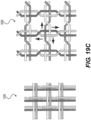
- Figure 19A also depicts a braiding structure of the intraluminal device without a twist before and after a junction frame.
- the intraluminal device may include a flexible shaft with twelve (12) wires and a mesh including twelve (12) wires.
- Figure 19C depicts a detailed view of the 12-wire row in Figure 19A .
- the twelve (12) wires may be formed, for example, by creating six strands of wires braided together: with three strands including two (2) wires each; while the other three strands may include two (2) wires each.
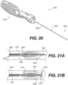
- the device 20000 may have the five following parts, for example:
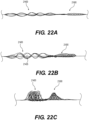
- the distal end of intraluminal device 20000 may be configured to penetrate a clot.
- proximal clot engaging mesh 21400 and clot anchoring segment 21600 may be pushed through clot 21800 until clot anchoring segment 21600 passes through the distal end of clot 21800 and is positioned within the portion of the vessel distal to the clot 21800.
- Proximal clot engaging mesh 21400 and clot anchoring segment 21600 may be configured to achieve small respective outer diameters when in their retracted states, such that they may penetrate and pass through clot 21800, such as by manipulation of handle 20100.
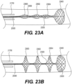
- proximal-most segment 23600 may have the largest expanded outer diameter and distal-most segment 23604 may have the smallest expanded outer diameter. In other embodiments, proximal-most segment 23600 may have the smallest expanded outer diameter and distal-most segment 23604 may have the largest expanded outer diameter. In still further embodiments, one or two of segments 23600-23604 may have expanded outer diameters which do not contact the vessel wall, while the remaining segments are configured to expand until they contact and conform with the vessel wall. Clot engaging mesh segment 23400 may be configured to have an outer expanded diameter which is equal to or larger than the expanded outer diameters of clot anchoring segments 23600-23604.
- At least one distal adjustable clot anchor 26600 may be arranged at the distal end of the intraluminal device.
- Clot anchor 26600 may be configured to expand with high radial force, forming a platform at the distal end of the device.
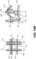
- clot anchor 26600 may be configured to expand until it contacts and conforms with the vessel wall. Once the intraluminal device is pulled proximally, the expanded clot anchor 26600 may engage the clot and push it proximally, in case that the clot engaging mesh segments 26402, 26404 did not capture the clot or a portion thereof.
- the second clot anchoring segment may have a larger expanded outer diameter than the first clot anchoring segment and/or exert greater outward force than the first clot anchoring segment when expanded.
- the second clot anchoring segment may be configured to expand until it contacts and conforms to the shape of the vessel wall.
- this may permit any clot fragments not captured by the first clot anchoring segment to be captured by the second clot anchoring segment.
- two or more of clot anchoring segments 27600-27608 may be expanded simultaneously, thus capturing the clot and any fragments thereof.
Landscapes
- Health & Medical Sciences (AREA)
- Life Sciences & Earth Sciences (AREA)
- Surgery (AREA)
- Heart & Thoracic Surgery (AREA)
- Public Health (AREA)
- Vascular Medicine (AREA)
- Engineering & Computer Science (AREA)
- Biomedical Technology (AREA)
- Veterinary Medicine (AREA)
- General Health & Medical Sciences (AREA)
- Animal Behavior & Ethology (AREA)
- Molecular Biology (AREA)
- Medical Informatics (AREA)
- Nuclear Medicine, Radiotherapy & Molecular Imaging (AREA)
- Orthopedic Medicine & Surgery (AREA)
- Cardiology (AREA)
- Oral & Maxillofacial Surgery (AREA)
- Transplantation (AREA)
- Surgical Instruments (AREA)
Description
- This application claims the benefit of priority from
U.S. Provisional Application No. 62/435,796, filed December 18, 2016 - This disclosure relates to intravascular and/or intraluminal medical devices that are configured to retrieve an obstruction from human blood vessels. Obstructions to be retrieved can include clots and clot material.
-
WO 2011106426 A1 discloses a medical device for recanalizing a vessel having a blockage and restoring blood flow through an obstructed blood vessel including an expandable member coupled to a core wire and a hypotube that are movable relative to each other to manipulate the expandable member between various configurations. -
GB 2 020 557 A - In an aspect, the disclosure provides an intraluminal device according to claim 1. Other features of the invention will be apparent from the dependent claims, and the description which follows. Further features of the present invention will become apparent from the following description of exemplary embodiments with reference to the attached drawings.
- The accompanying drawings, which are incorporated in and constitute a part of this specification, illustrate disclosed embodiments and, together with the description, serve to explain the disclosed embodiments.
-
Figure 1 is an illustration of a first exemplary intraluminal device, consistent with at least one of the disclosed embodiments; -
Figure 2 is an illustration of a second exemplary intraluminal device in accordance with at least one of the disclosed embodiments; -
Figure 3 is an illustration of a third exemplary intraluminal device in accordance with at least one of the disclosed embodiments; -
Figure 4 is an illustration of a fourth exemplary intraluminal device in accordance with at least one of the disclosed embodiments; -
Figure 5 is an illustration of a fifth exemplary intraluminal device in accordance with at least one of the disclosed embodiments; -
Figure 6 is an illustration of a sixth exemplary intraluminal device in accordance with at least one of the disclosed embodiments; -
Figure 7 is an illustration of a seventh exemplary intraluminal device in accordance with at least one of the disclosed embodiments; -
Figure 8 is an illustration of exemplary cable interweaving, such as is disclosed in connection withFigure 7 ; -
Figure 9A is an illustration of another exemplary intraluminal device in accordance with at least one of the disclosed embodiments; -
Figure 9B is an enlarged view of a portion of the exemplary intraluminal device shown inFigure 9A ; -
Figure 10A is an illustration of another exemplary intraluminal device in accordance with at least one of the disclosed embodiments; -
Figure 10B is a cross-sectional view of a portion of the exemplary intraluminal device shown inFigure 10A ; -
Figure 11 is an illustration of a braid structure of an exemplary intraluminal device; -
Figure 12 is an illustration of a braid structure of an exemplary intraluminal device in accordance with at least one of the disclosed embodiments; -
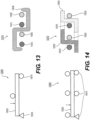
Figure 13 is a cross section view of an exemplary braided structure without twists, and an associated loaded beam diagram; -
Figure 14 is a cross section view of an exemplary braided structure with twists, and an associated loaded beam diagram; -
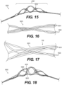
Figure 15 is an illustration of an exemplary intraluminal device, consistent with at least one of the disclosed embodiments; -
Figure 16 is an enlarged view of a portion of the exemplary intraluminal device shown inFigure 15 ; -
Figure 17 is an enlarged view of a portion of the exemplary intraluminal device shown inFigure 15 in an expanded position; -
Figure 18 is an illustration of exemplary intraluminal device in an expanded position in accordance with at least one of the disclosed embodiments; -
Figures 19A-C illustrate a number of braiding structures consistent with at least some of the disclosed embodiments; -
Figure 20 is an illustration of another exemplary intraluminal device in accordance with at least one of the disclosed embodiments; -
Figure 21A is an illustration of another exemplary intraluminal device in accordance with at least one of the disclosed embodiments; -
Figure 21B is an illustration of the exemplary intraluminal device shown inFigure 21A in an expanded positon; -
Figure 22A is an illustration of another exemplary intraluminal device in a first exemplary position in accordance with at least one of the disclosed embodiments; -
Figure 22B is an illustration of the exemplary intraluminal device shown inFigure 22A in a second exemplary positon; -
Figure 22C is an illustration of the exemplary intraluminal device shown inFigure 22A in a third exemplary positon; -
Figure 23A is an illustration of another exemplary intraluminal device in accordance with at least one of the disclosed embodiments; -
Figure 23B is an illustration of the exemplary intraluminal device shown inFigure 23A in an expanded positon; -
Figure 24 is an illustration of another exemplary intraluminal device in accordance with at least one of the disclosed embodiments; -
Figure 25 is an illustration of another exemplary intraluminal device in accordance with at least one of the disclosed embodiments; -
Figure 26A is an illustration of another exemplary intraluminal device in accordance with at least one of the disclosed embodiments; -
Figure 26B is an illustration of the exemplary intraluminal device shown inFigure 26A in an expanded positon; -
Figure 27 is an illustration of another exemplary intraluminal device in accordance with at least one of the disclosed embodiments; and -
Figure 28 is an illustration of another exemplary intraluminal device in accordance with at least one of the disclosed embodiments. - Annotations appearing in the figures are exemplary only, and are not restrictive of the invention as claimed.
- Reference will now be made in detail to the present embodiments (exemplary embodiments) of the disclosure, examples of which are illustrated in the accompanying drawings. Wherever possible, the same reference numbers will be used throughout the drawings to refer to the same or like parts.
-
Figure 1 illustrates an exemplaryintraluminal device 1000 including fivealternating wire zones Zones woven wires 1010 and may provide structural support forzones wires 1010 of zone 1 and 5 may be much smaller they also may provide a distal and proximal filter. (An example of variable sized openings is illustrated inFigures 10A-B , discussed below.) As a result, clot particles that might appear during the retrieval may be captured at these zones, for example. As further shown inFigure 1 ,zones wires 1020 to allow a large clot capturing area. And also shown inFigure 1 ,zones woven wires 1010. The number of zones illustrated are exemplary. More or less zones may be provided. -
Figure 2 illustrates anintraluminal device 2000 in a more open position than illustrated inFigure 1 , highlighting theclot entry cells 2020 that may be made from the loopedwires 1020. As further shown inFigure 2 ,zones wires 1020 to allow a large clot capturing area. -
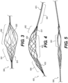
Figure 3 illustrates yet another exemplaryintraluminal device 3000. In this example, as shown inFigure 3 , thedevice 3000 may be configured so as to include only two different zones.Zone 3001 may be constructed from a group ofwoven wires 3010, such as for example, densely braided, which provides structural support for thedevice 3000. In addition,zone 3001 may also serve as a distal filter that prevents emboli from the distal vasculature. As also shown infigure 3 ,zone 3002 may be constructed from wires which are looped which are longitudinally located and provide theclot entry zone 3020. Additionally,zone 3001 may, for example, give structural support and may also serve as a distal filter. As further shown inFigure 3 ,zone 3002 may be the clot entering zone. -
Figure 4 illustrates yet another exemplaryintraluminal device 4000 with four regions. In thefirst region 4001, the wires may be twisted or coiled to form ashaft 4015. In thesecond region 4002, the wires may be woven to from ascaffold 4017 that supports the opening of thethird region 4003. In thethird region 4003, the wires may be woven set in looped pairs to form aclot capture structure 4020. For example, the wires of thethird region 4003 may be loosely looped or loosely coupled. Further, thefourth region 4004 may be woven to form adistal filter 4030 that captures distal emboli or clot particles. Thefourth region 4004 may also serve as a scaffold for thethird region 4003. -
Figure 5 illustrates yet another exemplaryintraluminal device 5000. For example, as shown infigure 5 , theclot opening region 5001 may be woven from three wires that are looped together. Further, the number of wires that are looped together may be greater than two. -
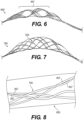
Figure 6 is illustrates yet another exemplaryintraluminal device 6000. For example, as shown infigure 6 , theclot opening region 6001 may be woven from three wires that are loosely looped together. Further, the number of wires that are looped together may be greater than two. -
Figure 7 illustrates yet another exemplaryintraluminal device 7000. For example, as shown inFigure 7 , thedevice 7000 may include sixcables 7025, in which eachcable 7025 may include paired wires. This may create a strong but flexible crossing. And this may further allow, for example, thedevice 7000 to achieve a flexible structure with a high radial force. -
Figure 8 illustrates an example ofcable interweaving 8000, as discussed above. Eachcable 7025, for example, may be made from a looped pair ofwires 8027 that are woven with a pair ofwires 8027 from a crossing cable. As a result, for example, a semi-flexible and strong crossing point may be achieved. -
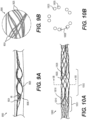
Figures 9A-9B illustrate yet another exemplary intraluminal device. As shown infigure 9A , the cables, for example, may be made from three wires that are unwound and then woven together with the wires from the crossing cable.Figure 9B also illustrates thecable crossing point 9006 where the cables (which includeswires 9024 and 9025) are unwound and woven back together. As discussed below in connection withFigures 12 and19 , the braiding structure ofFigure 9A may include a 12-wire braiding structure with a twist before and after each junction frame. - As discussed above in connection with
Figure 1 ,Figure 10A illustratesdevice 10000 with variable-sized openings.Region 10001 includes groups of wovenwires 10010 adjacent tointermediate location 10002, and may provide structural support forintermediate location 10002. Specifically, the groupings of wovenwires 10010 inregion 10001 can provide the support to hold open thefirst interstices 10028. Thefirst interstices 10028 are larger than thesecond interstices 10018, where the second interstices are present inregion 10001. The cross section illustrated inFigure 10B depicts how thecables 10025 are circumferentially displaced in theintermediate location 10002.Cables 10025 are generally circumferentially displaced about a central region. Moreover,first interstices 10028 may provide relatively large openings for clot entry in theintermediate location 10002. - In accordance with embodiments consistent with the present disclosure, the exemplary intraluminal device may include, for example, two braiding mechanisms, configurations, or structures which may help increase the performance of the device relative to a device incorporating standard braiding structures.
- For example, as shown in
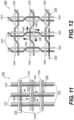
Figure 12 , in accordance with at least some embodiments of an intraluminal device consistent with the present disclosure, thebraiding structure 12000 may include a twist of wires before and after eachjunction frame 12050.Braiding structure 12000 includes three strands of two-wire pairs (twowires 12015 and 12025) braided with three stands of two-wire pairs (twowires 12030 and 12040).Figure 12 depicts a total of nine (9) junction frames. The junction position within the mesh structure may help prevent slipping of wires across the twist which may otherwise work to become homogeneously separated on a circumference of a mesh structure of an intraluminal device. While abraid structure 11000, as shown inFigure 11 , may enable slippage (illustrated by arrows 11005) until the wire 11040 (for example) reaches aparallel wire 11030, the twists as shown inbraiding structure 12000 shown inFigure 12 , may operate to help prohibit substantial slippage across the twist and enable a solid structure when the intraluminal device is expanded. - In accordance with at least some embodiments of an intraluminal device consistent with the present disclosure, and as illustrated in
Figures 13 and 14 , a braiding structure which includes a twist structure may add strength to a mesh structure by operating as a restraint system grasping the wire and dividing an external force applied on the mesh onto additional elements.Figure 13 depictscross section 11010 ofbraiding structure 11000 ofFigure 11 andFigure 14 depictscross section 12010 ofbraiding structure 12000 ofFigure 12 . The dotted lines incross section 12010 ofFigure 14 illustrate a twist inwires wires Figures 13 and 14 with the loaded beam diagram 13000 (associated with braided structure 11000) and loaded beam diagram 14000 (associated with braided structure 12000). As illustrated inFigures 13 and 14 , a loadedbeam 13020 with threesupports 14010, for example, will react to and distribute the force more effectively than a loadedbeam 13020 with twosupports 13010, as there is a smaller distance between threesupports 14010. - In accordance with at least some embodiments consistent with the present disclosure, the exemplary intraluminal device may be delivered through a microcatheter with an internal diameter of between 0.013 inches (0.033 centimeters) and 0.027 inches (0.069 centimeters). In some embodiments, the microcatheter may have an internal diameter of 0.017 inches (0.043 centimeters). As a result, the exemplary intraluminal device may have a low profile (in a retracted or compressed state) that is less than that of the internal diameter of a microcatheter. In accordance with at least some embodiments of an intraluminal device consistent with the present disclosure, the device may have the five following parts, for example:
- a) a control handle;
- b) a stiff proximal shaft (for example, a stainless steel hypotube);
- c) a flexible shaft (made from a cable of wires, for example);
- d) an expandable mesh which is made from the same wires of the cable; and
- e) a corewire/control wire which may be connected to the distal tip of the mesh and runs through the shafts to the handle.
- For example, as illustrated in the 8-wire row in
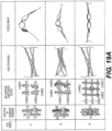
Figure 19A , an intraluminal device may include a flexible shaft with eight (8) wires (each wire having a diameter of 70µm) and a mesh including eight (8) wires (each wire having a diameter of 70 µm). The eight wires, for example, may be formed, for example, by creating four strands of wires braided together, with each strand including two (2) wires each. As shown inFigure 19A , and discussed above, the braiding structure of the intraluminal device may include a twist of wires before and after each junction frame to help prevent slippage. A detailed view of cable interweaving 8000 (discussed in connection withFigure 8 ) is also shown inFigure 19A .Cable interweaving 8000 illustrates a junction in the braiding structure of the intraluminal device in detail. The wires may, for example, be made from Nitinol.Figure 19A also depicts a braiding structure of the intraluminal device without a twist before and after a junction frame. - In another exemplary embodiment, as illustrated in the 12-wire row in
Figure 19A , the intraluminal device may include a flexible shaft with twelve (12) wires and a mesh including twelve (12) wires.Figure 19C depicts a detailed view of the 12-wire row inFigure 19A . The twelve (12) wires may be formed, for example, by creating six strands of wires braided together: with three strands including two (2) wires each; while the other three strands may include two (2) wires each. As shown inFigure 19C , and as discussed above (such as in connection withFigures 8 , which showscable interweaving 8000, andFigure 12 , which shows braiding structure 12000), thebraiding structure 12000 for this embodiment may include a twist of wires before and after each junction frame to help prevent slippage.Figure 19C also depictsbraiding structure 11000 without a twist before and after a junction frame. An exemplary intraluminal device with twelve (12) wires includesdevice 9000 ofFigure 9 . - In accordance with another embodiment consistent with the present disclosure, as illustrated in the 10-wire row in
Figure 19 , the flexible shaft of the exemplary intraluminal device may include a flexible shaft with ten (10) wires and a mesh including ten (10) wires.Figure 19B depicts a detailed view of the 10-wire row inFigure 19A . The ten (10) wires may be formed, for example, by creating four strands of wires braided together: with two strands including three (3) wires each; while the other two strands may include two (2) wires each. Exemplary braiding structures with ten (10) wires are illustrated inFigure 19B . Thebraiding structure 19500 may include a twist of wires before and after each junction frame.Braiding structure 19500 includes two-wire strand (wires 12015 and 12025) and three-wire strand (wires wires 12030 and 12040) and three-wire strand (12030, 12040, and 19040).Slippage arrows 19505 are also shown. Abraiding structure 19400 without a twist is also illustrated.Braiding structure 19400 includes two-wire strand (wires 11015 and 11025) and three-wire strand (wires wires 11030 and 11040) and three-wire strand (11030, 11040, and 19030).Slippage arrows 19005 are also shown. In each strand of wires, the wires may, for example, be intertwined to create a stable strand. The wires may, for example, be made from Nitinol, and this configuration may be achieved, for example, by cutting two wires at a transition between a cable and mesh (although this may involve another manufacturing step). As shown inFigure 15 , which represents a general view of an exemplaryintraluminal device 15000 in accordance with the present disclosure, the strands may cross each other to create large openings (cells). In the intersections, for example, the strands may be intertwined with one another to create a loosely coupled junction. Before and after the junction, for example, the wires of the strands may be intertwined. - As shown in
Fig. 16 , a strand of two wires (i.e., wires 16020) may cross a strand of three wires (i.e., wires 16010). The intertwined wires before and after the junction and the intertwining of the wires inside the junction may create a loosely coupled but stable junction and cross-section, which helps prevent slippage and create large cells, ultimately helping to resist collapse of the device when expanded with high radial force within a tube. And, as shown inFigures 17-18 (whereFigure 17 is a detail ofregion 16015 ofFigure 16 in an expanded configuration, andFigure 18 is a detail ofFigure 15 in an expanded configuration), when the mesh is expanded, the junction structure keeps the wires together even when the mesh is expanded. As a result, the mesh size remains the same. -
Figures 19A-C illustrate 8-, 10-, and 12-wire junctions and configurations. In addition, as discussed above,devices Figures 16 and 17 may use the 12-wire junctions ofFigures 19A and19C . Of course, these are only examples, and the wire junctions and configurations with more or less wires may be used, and that regardless of the number of wires, differing braiding arrangements may be employed. - As shown in
Figure 20 , in accordance with at least some alternative embodiments of anintraluminal device 20000 in accordance with the present disclosure, thedevice 20000 may have the five following parts, for example: - a) a
control handle 20100; - b) a stiff
proximal shaft 20200, such as a stainless steel hypotube; - c) a flexible shaft 20300 (made from a cable of wires, for example);
- d)
clot engaging component 20400, such as an clot engaging expandable mesh and/or an clot anchor platform which is made from the same wires of the cable offlexible shaft 20300; and - e) a corewire or control wire (not shown in
Figure 20 ) which may be connected to the distal tip of the mesh ofclot engaging component 20400 and which runs through theshafts handle 20100. - As shown in
Figures 21A-B and22A-C , in accordance with at least some embodiments of anintraluminal device 20000 in accordance with the present disclosure, theclot engaging component 20400 ofintraluminal device 20000 may include aclot anchoring segment 21600 distal to aclot engaging mesh 21400, configured to engagehard clots 21800. Theclot anchoring segment 21600 may be manually adjustable and/or self-expandable. In some embodiments,clot anchoring segment 21600 may be heat-treated such that it is configured to expand radially outward when released fromcatheter 21700. According to various embodiments in whichclot anchoring segment 21600 is manually adjustable, its expansion may be controlled, at least in part, by a control wire. In some embodiments, the distal end of acontrol wire 21550 may be connected to a portion ofclot anchoring segment 21600, such as the distal portion thereof. In some embodiments, proximalclot engaging mesh 21400 andclot anchoring segment 21600 may be a unitary structure or may be connected together, such that a force (e.g. a pulling force) exerted uponclot anchoring segment 21600 by thecontrol wire 21550 may transfer toclot engaging mesh 21400, causing simultaneous adjustment ofclot anchoring segment 21600 and proximalclot engaging mesh 21400. According to various embodiments in whichclot anchoring segment 21600 is self-expanding, acontrol wire 21500 may be connected to a portion of proximalclot engaging mesh 21400, such as the distal end thereof. - In accordance with alternative embodiments, the intraluminal device may have two or more control wires which run through the
shafts handle 20100. Afirst control wire 21500 may be connected to proximalclot engaging mesh 21400, such as the distal end thereof, and may be actuated to control expansion of proximalclot engaging mesh 21400. Asecond control wire 21550 may be connected to a portion ofclot anchoring segment 21600, such as a distal end thereof, and may be actuated to control expansion ofclot anchoring segment 21600. - In accordance with at least some embodiments of the present disclosure, the outer diameter of proximal
clot engaging mesh 21400 may be equal to or larger than the outer diameter ofclot anchoring segment 21600 when they are in their respective retracted states. For example,Figure 22A illustrates an embodiment in which proximalclot engaging mesh 21400 andclot anchoring segment 21600 are both retracted. Additionally or alternatively, the outer diameter of proximalclot engaging mesh 21400 may be equal to or larger than the outer diameter ofclot anchoring segment 21600 when they are in their respective fully-expanded states. For example,Figure 22C illustrates an embodiment in which proximalclot engaging mesh 21400 andclot anchoring segment 21600 are both fully expanded. As explained above, proximalclot engaging mesh 21400 may be configured for expansion independent ofclot anchoring segment 21600, and vice versa. For example,Figure 22B illustrated an embodiment in which proximalclot engaging mesh 21400 is expanded whileclot anchoring segment 21600 remains retracted. Proximalclot engaging mesh 21400 may include at least onepore 21405 which is larger than other openings in the intraluminal device, including pores ofclot anchoring segment 21600. The at least onepore 21405 may form a clot capturing area, allowing capture of clots within proximalclot engaging mesh 21400. In various embodiments, proximalclot engaging mesh 21400 may be configured for at least partial penetration of a clot and for expansion within the clot, either via a self-expansion mechanism or by actuation of at least one control cable. Proximalclot engaging mesh 21400 may exert an outward radial force upon the clot, achieving fracture and/or capture of the clot. - According to various embodiments, the distal end of
intraluminal device 20000 may be configured to penetrate a clot. As illustrated inFigures 21A-B , proximalclot engaging mesh 21400 andclot anchoring segment 21600 may be pushed throughclot 21800 untilclot anchoring segment 21600 passes through the distal end ofclot 21800 and is positioned within the portion of the vessel distal to theclot 21800. Proximalclot engaging mesh 21400 andclot anchoring segment 21600 may be configured to achieve small respective outer diameters when in their retracted states, such that they may penetrate and pass throughclot 21800, such as by manipulation ofhandle 20100. Proximalclot engaging mesh 21400 may be expanded to capture theclot 21800. However, according to embodiments in whichclot 21800 is too rigid for expansion of proximalclot engaging mesh 21400,clot anchoring segment 21600 may be expanded since it is positioned distal to the clot. According to some embodiments, the outer diameter of expandedclot anchoring segment 21600 may be smaller than the inner diameter of the blood vessel, such thatclot anchoring segment 21600 does not contact the vessel wall. Alternatively,clot anchoring segment 21600 may be configured to expand until it contacts and conforms to the shape of the vessel wall. Expansion ofclot anchoring segment 21600 may form a platform which may trapclot 21800 and prevent it from traveling distal toclot anchoring segment 21600. Once theintraluminal device 20000 is pulled proximally,clot anchoring segment 21600 may engage theclot 21800 and push it upstream. Any adhesion between theclot 21800 and the vessel may be overcome by the resultant shear forces. In some embodiments, partial expansion of proximalclot engaging mesh 21400 withinclot 21800 may at least partiallysecure clot 21800 to proximalclot engaging mesh 21400. Once the clot is pushed proximally byclot anchoring segment 21600 and disengages from the vessel wall, theclot 21800 may be retrieved into the guidingcatheter 21700. In some embodiments, at least one of proximalclot engaging mesh 21400 andclot anchoring segment 21600 may remain expanded until theclot 21800 is captured withincatheter 21700. - As depicted in
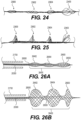
Figures 23A-B ,24, and 25 , in accordance with at least some alternative embodiments of anintraluminal device 20000 in accordance with the present disclosure, theintraluminal device 20000 may include at least one clot anchoring segment and an expandable clot engagingmesh segment 23400 at the distal end thereof. The embodiment depicted inFigures 23A-B ,24, and 25 include threeclot anchoring segments intraluminal device 20000 may include one, two, three, four, five, or more anchoring segments according to various embodiments. Clot engagingmesh segment 23400 may be manually expandable, such as by actuation ofcontrol wire 23550, and/or self-expanding, according to mechanisms discussed above, and may be configured to engage hard clots. According to some embodiments, clot anchoring segments 23600-23604 may be expanded by asingle control wire 23500 that is connected to the most distal end of these segments, such as thedistal-most segment 23604. Alternatively, eachclot anchoring segment mesh segment 23400 may be equal to or larger than the outer diameter of at least one of clot anchoring segments 23600-23604 when in the retracted state. - As illustrated in
Figure 23B , the clot anchoring segments 23600-23604 may be expanded with high radial forces, each forming a platform configured to substantially prevent passage of clots thereby. According to some embodiments, the outer diameters of expanded clot anchoring segments 23600-23604 may be substantially equal and smaller than the inner diameter of the blood vessel, such that the clot anchoring segments 23600-23604 do not contact the vessel wall. According to alternative embodiments, clot anchoring segments 23600-23604 may be configured to expand until each contacts and conforms to the shape of the vessel wall. In still further embodiments, clot anchoring segments 23600-23604 may be configured for varying outer diameters when fully expanded. In some embodiments,proximal-most segment 23600 may have the largest expanded outer diameter anddistal-most segment 23604 may have the smallest expanded outer diameter. In other embodiments,proximal-most segment 23600 may have the smallest expanded outer diameter anddistal-most segment 23604 may have the largest expanded outer diameter. In still further embodiments, one or two of segments 23600-23604 may have expanded outer diameters which do not contact the vessel wall, while the remaining segments are configured to expand until they contact and conform with the vessel wall. Clot engagingmesh segment 23400 may be configured to have an outer expanded diameter which is equal to or larger than the expanded outer diameters of clot anchoring segments 23600-23604. Clot engagingmesh segment 23400 may be configured to self-expand independently of clot anchoring segments 23600-23604. For example,Figure 24 illustrates an embodiment in which clot anchoring segments 23600-23604 are retracted and clot engagingmesh segment 23400 is expanded. whileFigure 25 illustrates an embodiment in which clot anchoring segments 23600-23604 and clot engagingmesh segment 23400 are all expanded. - When expanded, clot anchoring segments 23600-23604 may each form a platform with a larger outer diameter than that of any adjoining section between clot anchoring segments. For example, the transition between clot anchoring segment and adjoining section may be steep so as to form a shelf or seat capable of seating against a portion of a clot. The clot may be trapped between adjacent platforms, and then pushed (or pulled) as the device is retrieved proximally. As shown in
Figures 23A-B , the clot engaging mesh segment 23400 (which can function as a distal self-expanding filter) may be configured to catch any detached clot fragments to secure a clean pass. - According to some embodiments, the intraluminal device may be delivered into a blood vessel, in proximity to a blood clot. Clot anchoring segments 23600-23604 and clot engaging
mesh segment 23400 may be in their retracted states during delivery. The intraluminal device may be positioned such that clot engagingmesh segment 23400 is positioned distal to the clot location, with the clot positioned distal to at least one of clot anchoring segments 23600-23604. In some embodiments, the clot may be positioned proximal to proximal-mostclot anchoring segment 23600. Additionally or alternatively, the clot may be positioned between two consecutive clot anchoring segments. Clot engagingmesh segment 23400 may self-expand or be expanded manually to catch any clot fragments distal to the clot anchoring segments. Before, during, or after expansion of clot engagingmesh segment 23400, the clot anchoring segments 23600-23604 may be expanded, either simultaneously or individually. In some embodiments, distalclot anchoring segment 23604 may be expanded first and proximalclot anchoring segment 23600 may be expanded last. Alternatively, in some embodiments, proximalclot anchoring segment 23600 may be expanded first and distalclot anchoring segment 23604 may be expanded last. Expansion of the clot anchoring segments 23600-23604 may form platforms which may trap the clot. The intraluminal device may be pulled proximally, causing the clot anchoring segments to push the clot proximally and into guidingcatheter 21700. In some embodiments, at least one of clot anchoring segments 23600-23604 and clot engagingmesh segment 23400 may remain expanded until the clot is captured and removed from the vessel. - As depicted in
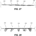
Figures 26A-B , in accordance with another embodiment, theintraluminal device 20000 may include a longclot engaging segment 26400. The longclot engaging segment 26400 may include several sequential adjustable clot engagingmesh segments clot engaging segment 26400 may include two, three, four five, or more adjustable clot engaging mesh segments. The clot engagingmesh segments mesh segments mesh segments - As also illustrated in
Figures 26A-B , in accordance with at least some embodiments of anintraluminal device 20000 in accordance with the present disclosure, at least one distaladjustable clot anchor 26600 may be arranged at the distal end of the intraluminal device.Clot anchor 26600 may be configured to expand with high radial force, forming a platform at the distal end of the device. For example,clot anchor 26600 may be configured to expand until it contacts and conforms with the vessel wall. Once the intraluminal device is pulled proximally, the expandedclot anchor 26600 may engage the clot and push it proximally, in case that the clot engagingmesh segments mesh segments adjustable clot anchor 26600 may remain expanded until the clot is captured and removed from the vessel. Furthermore, acontrol wire 26550 may be attached to thedistal-most anchoring segment 26600, and/or one or more control wires (such as control wire 26500) may be attached to the distal portion of one or more clot engagingmesh segments - As depicted in
Figures 27-28 , in accordance with another embodiment, theintraluminal device 20000 may include several adjustable clot anchoring segments 27600-27608, each of which may be configured to change its respective configuration to consequent platforms when expanded, to allow clot entrapment between the platforms. The intraluminal device may include two, three, four, five, six, seven, eight, nine, ten, or more clot anchoring segments. The clot anchoring segments 27600-27608 may vary in radial force, wire arrangement, diameter, pore size, sparse and design, for example. In some embodiments, each clot anchoring segment 27600-27608 may include a respective control wire, such that the segments may be individually expanded. In other embodiments, a single or multiple control wires may be attached to the distal-most clot anchoring segment and may be actuated to simultaneously expand all clot anchoring segments 27600-27608. In one embodiment, a first one of the clot anchoring segments 27600-27608 may be expanded distal to a clot location, so as to capture the clot. In the event that the clot anchoring segment does not capture the clot or at least a fragment thereof, a second clot anchoring segment may be expanded, for example distal to the first clot anchoring segment, to capture the remaining fragments of the clot. In some embodiments, the second clot anchoring segment may have a larger expanded outer diameter than the first clot anchoring segment and/or exert greater outward force than the first clot anchoring segment when expanded. For example, the second clot anchoring segment may be configured to expand until it contacts and conforms to the shape of the vessel wall. Advantageously, this may permit any clot fragments not captured by the first clot anchoring segment to be captured by the second clot anchoring segment. According to other embodiments, two or more of clot anchoring segments 27600-27608 may be expanded simultaneously, thus capturing the clot and any fragments thereof. Once the device is pulled proximally, the platforms formed by clot anchoring segments 27600-27608 may engage the clot and any fragments thereof and push it proximally. The platforms may also act as a filter, catching detached clot fragments. In some embodiments, at least one of clot anchoring segments 27600-27608 may remain expanded until the clot is captured and removed from the vessel. - The elements in the claims are to be interpreted broadly based on the language employed in the claims and not limited to examples described in the present specification or during the prosecution of the application, which examples are to be construed as non-exclusive. Further, the steps of the disclosed methods can be modified in any manner, including by reordering steps or inserting or deleting steps. It is intended, therefore, that the specification and examples be considered as example only.
Claims (10)
- An intraluminal device including an elongated structure formed of a plurality of wires, the intraluminal device comprising:a first region wherein the plurality of wires are twisted to form a shaft (20300);a second region, adjacent to the first region, wherein the plurality of wires are woven to form a scaffold;a third region, wherein the plurality of wires are separated into sets of looped pairs to form at least one clot engaging expandable mesh segment (21400); anda fourth region, including at least one clot anchoring segment (21600), wherein the clot anchoring segment (21600) is expandable to form a platform configured to engage a clot and push the clot proximally as the device is retrieved from a vessel, wherein the at least one clot anchoring segment (21600) and the at least one clot engaging expandable mesh segment (21400) are configured for independent expansion.
- The intraluminal device of claim 1, wherein the at least one clot anchoring segment (21600) self-expands and a control wire (21500) is connected to a distal end of the at least one clot engaging expandable mesh segment (21400).
- The intraluminal device of claim 1, wherein the device includes a first control wire (21500) and a second control wire (21550); wherein the first control wire (21500) controls expansion of the at least one clot engaging expandable mesh segment (21400) and the second control wire (21550) controls the expansion of the at least one clot anchoring segment (21600).
- The intraluminal device of claim 1, wherein the at least one clot engaging expandable mesh segment (21400) includes large pores and is self-expanded or controllably adjusted while applying radial force to penetrate and contain the clot.
- The intraluminal device of claim 1, wherein the at least one clot anchoring segment (21600) includes two adjustable clot anchoring segments.
- The intraluminal device of claim 5, wherein the two adjustable clot anchoring segments are expanded by a single control wire that is connected to a distal end of the two adjustable clot anchoring segments.
- The intraluminal device of claim 5, wherein the two adjustable clot anchoring segments are expanded by separate control wires.
- The intraluminal device of claim 1, wherein the at least one clot engaging expandable mesh segment includes two adjustable mesh segments.
- The intraluminal device of any preceding claim, wherein the at least one clot anchoring segment (21600) is situated at a distal end of the at least one clot engaging expandable mesh segment (21400).
- The intraluminal device of any preceding claim, wherein the at least one clot anchoring segment (21600) is configured such that, once deployed in the vessel in an expanded state, the at least one clot anchoring segment (21600) remains in the expanded state until the device is removed from the vessel.
Applications Claiming Priority (2)
| Application Number | Priority Date | Filing Date | Title |
|---|---|---|---|
| US201662435796P | 2016-12-18 | 2016-12-18 | |
| PCT/IB2017/001773 WO2018109566A2 (en) | 2016-12-18 | 2017-12-18 | Controllable retriever with distal clot anchor |
Publications (3)
| Publication Number | Publication Date |
|---|---|
| EP3554422A2 EP3554422A2 (en) | 2019-10-23 |
| EP3554422A4 EP3554422A4 (en) | 2020-07-08 |
| EP3554422B1 true EP3554422B1 (en) | 2024-07-03 |
Family
ID=62558131
Family Applications (1)
| Application Number | Title | Priority Date | Filing Date |
|---|---|---|---|
| EP17880659.2A Active EP3554422B1 (en) | 2016-12-18 | 2017-12-18 | Controllable retriever with distal clot anchor |
Country Status (8)
| Country | Link |
|---|---|
| US (3) | US11980380B2 (en) |
| EP (1) | EP3554422B1 (en) |
| JP (1) | JP7369034B2 (en) |
| KR (1) | KR20190095404A (en) |
| CN (1) | CN110325149A (en) |
| AU (1) | AU2017374846A1 (en) |
| IL (1) | IL267294B2 (en) |
| WO (2) | WO2018109566A2 (en) |
Families Citing this family (44)
| Publication number | Priority date | Publication date | Assignee | Title |
|---|---|---|---|---|
| US9402707B2 (en) | 2008-07-22 | 2016-08-02 | Neuravi Limited | Clot capture systems and associated methods |
| EP2629684B1 (en) | 2010-10-22 | 2018-07-25 | Neuravi Limited | Clot engagement and removal system |
| US11259824B2 (en) | 2011-03-09 | 2022-03-01 | Neuravi Limited | Clot retrieval device for removing occlusive clot from a blood vessel |
| US12076037B2 (en) | 2011-03-09 | 2024-09-03 | Neuravi Limited | Systems and methods to restore perfusion to a vessel |
| EP4566553A3 (en) | 2011-03-09 | 2025-08-06 | Neuravi Limited | A clot retrieval device for removing occlusive clot from a blood vessel |
| PL2967610T3 (en) | 2013-03-14 | 2019-07-31 | Neuravi Limited | A clot retrieval device for removing occlusive clot from a blood vessel |
| US9433429B2 (en) | 2013-03-14 | 2016-09-06 | Neuravi Limited | Clot retrieval devices |
| WO2014140092A2 (en) | 2013-03-14 | 2014-09-18 | Neuravi Limited | Devices and methods for removal of acute blockages from blood vessels |
| WO2016083472A1 (en) | 2014-11-26 | 2016-06-02 | Neuravi Limited | A clot retrieval device for removing occlusive clot from a blood vessel |
| US11253278B2 (en) | 2014-11-26 | 2022-02-22 | Neuravi Limited | Clot retrieval system for removing occlusive clot from a blood vessel |
| US10617435B2 (en) | 2014-11-26 | 2020-04-14 | Neuravi Limited | Clot retrieval device for removing clot from a blood vessel |
| ES2577288B8 (en) | 2015-01-13 | 2019-01-10 | Anaconda Biomed S L | Device for thrombectomy |
| US12575845B2 (en) | 2015-12-11 | 2026-03-17 | Anaconda Biomed, S.L. | Thrombectomy device, system and method for extraction of vascular thrombi from a blood vessel |
| US11771446B2 (en) | 2020-10-19 | 2023-10-03 | Anaconda Biomed, S.L. | Thrombectomy system and method of use |
| CA3035706A1 (en) | 2016-09-06 | 2018-03-15 | Neuravi Limited | A clot retrieval device for removing occlusive clot from a blood vessel |
| WO2018109566A2 (en) * | 2016-12-18 | 2018-06-21 | Rapid Medical Ltd. | Controllable retriever with distal clot anchor |
| EP3673839A4 (en) * | 2017-08-23 | 2021-04-28 | Inc. Piolax Medical Devices | TRAP TOOL FOR INTRALUMINAL FOREIGN BODIES |
| EP3826557A4 (en) * | 2018-07-26 | 2022-04-27 | Rapid Medical Ltd. | Intraluminal device with wire braiding configuration |
| CN118680654A (en) * | 2018-07-31 | 2024-09-24 | 波士顿科学医学有限公司 | Retrieval device |
| US10842498B2 (en) | 2018-09-13 | 2020-11-24 | Neuravi Limited | Systems and methods of restoring perfusion to a vessel |
| US11406416B2 (en) | 2018-10-02 | 2022-08-09 | Neuravi Limited | Joint assembly for vasculature obstruction capture device |
| EP3639768A1 (en) | 2018-10-16 | 2020-04-22 | Anaconda Biomed, S.L. | A device for extraction of thrombus from a blood vessel and a thrombectomy apparatus |
| US12569264B2 (en) | 2018-10-16 | 2026-03-10 | Anaconda Biomed, S.L. | Device and a thrombectomy apparatus for extraction of thrombus from a blood vessel |
| CN113795204A (en) | 2019-01-11 | 2021-12-14 | 阿纳康达生物医学有限公司 | Loading device and method for loading a medical device into a catheter |
| KR102232949B1 (en) * | 2019-07-29 | 2021-03-26 | 주식회사 엔벤트릭 | Device for removing clot |
| US11712231B2 (en) | 2019-10-29 | 2023-08-01 | Neuravi Limited | Proximal locking assembly design for dual stent mechanical thrombectomy device |
| US11517340B2 (en) | 2019-12-03 | 2022-12-06 | Neuravi Limited | Stentriever devices for removing an occlusive clot from a vessel and methods thereof |
| US11730501B2 (en) | 2020-04-17 | 2023-08-22 | Neuravi Limited | Floating clot retrieval device for removing clots from a blood vessel |
| US11871946B2 (en) | 2020-04-17 | 2024-01-16 | Neuravi Limited | Clot retrieval device for removing clot from a blood vessel |
| US11717308B2 (en) | 2020-04-17 | 2023-08-08 | Neuravi Limited | Clot retrieval device for removing heterogeneous clots from a blood vessel |
| US11737771B2 (en) | 2020-06-18 | 2023-08-29 | Neuravi Limited | Dual channel thrombectomy device |
| US11937836B2 (en) | 2020-06-22 | 2024-03-26 | Neuravi Limited | Clot retrieval system with expandable clot engaging framework |
| US11395669B2 (en) | 2020-06-23 | 2022-07-26 | Neuravi Limited | Clot retrieval device with flexible collapsible frame |
| US11439418B2 (en) | 2020-06-23 | 2022-09-13 | Neuravi Limited | Clot retrieval device for removing clot from a blood vessel |
| US20220054139A1 (en) * | 2020-08-18 | 2022-02-24 | Merit Medical Systems, Inc. | Embolic basket, particles, and related methods |
| US11864781B2 (en) | 2020-09-23 | 2024-01-09 | Neuravi Limited | Rotating frame thrombectomy device |
| US11937837B2 (en) | 2020-12-29 | 2024-03-26 | Neuravi Limited | Fibrin rich / soft clot mechanical thrombectomy device |
| US12029442B2 (en) | 2021-01-14 | 2024-07-09 | Neuravi Limited | Systems and methods for a dual elongated member clot retrieval apparatus |
| US12064130B2 (en) | 2021-03-18 | 2024-08-20 | Neuravi Limited | Vascular obstruction retrieval device having sliding cages pinch mechanism |
| US11974764B2 (en) | 2021-06-04 | 2024-05-07 | Neuravi Limited | Self-orienting rotating stentriever pinching cells |
| KR102606780B1 (en) | 2021-09-16 | 2023-11-29 | 주식회사 푸른엔텍 | Body for preventing painting booth |
| KR20230040499A (en) | 2021-09-16 | 2023-03-23 | 주식회사 푸른엔텍 | Prevention device for painting booth |
| US20230210545A1 (en) * | 2021-12-30 | 2023-07-06 | Deepin Technologies, LLC. | Expandable intraluminal device |
| CN115350383B (en) * | 2022-08-30 | 2023-05-23 | 铂珑生物科技(苏州)有限公司 | Balloon catheter system |
Citations (1)
| Publication number | Priority date | Publication date | Assignee | Title |
|---|---|---|---|---|
| US20110213403A1 (en) * | 2010-02-23 | 2011-09-01 | Maria Aboytes | Devices and methods for vascular recanalization |
Family Cites Families (22)
| Publication number | Priority date | Publication date | Assignee | Title |
|---|---|---|---|---|
| DE2821048C2 (en) * | 1978-05-13 | 1980-07-17 | Willy Ruesch Gmbh & Co Kg, 7053 Kernen | Medical instrument |
| US5490859A (en) | 1992-11-13 | 1996-02-13 | Scimed Life Systems, Inc. | Expandable intravascular occlusion material removal devices and methods of use |
| US5846261A (en) * | 1994-07-08 | 1998-12-08 | Aga Medical Corp. | Percutaneous catheter directed occlusion devices |
| US20020169474A1 (en) * | 1999-03-08 | 2002-11-14 | Microvena Corporation | Minimally invasive medical device deployment and retrieval system |
| JP5102931B2 (en) * | 2001-01-09 | 2012-12-19 | マイクロベンション インコーポレイテッド | Embolization catheter and system having the catheter |
| DE10242444A1 (en) * | 2002-09-11 | 2004-04-01 | pfm Produkte für die Medizin AG | extractor |
| US8585713B2 (en) * | 2007-10-17 | 2013-11-19 | Covidien Lp | Expandable tip assembly for thrombus management |
| US9492263B2 (en) | 2007-12-10 | 2016-11-15 | Incept, Llc | Retrieval apparatus and methods for use |
| JP5385302B2 (en) * | 2007-12-26 | 2014-01-08 | ラザラス エフェクト, インコーポレイテッド | Recovery system and method of use |
| US8864792B2 (en) * | 2008-08-29 | 2014-10-21 | Rapid Medical, Ltd. | Device and method for clot engagement |
| DE102009042121B3 (en) * | 2009-09-18 | 2011-04-21 | Acandis Gmbh & Co. Kg | Medical device for insertion into a hollow body organ |
| CA2874586C (en) * | 2011-05-23 | 2019-07-09 | Lazarus Effect, Inc. | Retrieval systems and methods for use thereof |
| US20130030460A1 (en) * | 2011-07-26 | 2013-01-31 | Marks Michael P | Intravascular thromboembolectomy device and method using the same |
| WO2013102848A2 (en) | 2012-01-04 | 2013-07-11 | Rapid Medical Ltd. | Devices and methods for assisting medical treatments |
| CN107432760A (en) | 2012-01-17 | 2017-12-05 | 珀弗娄医疗有限公司 | Method and apparatus for removing tamper |
| US9314248B2 (en) | 2012-11-06 | 2016-04-19 | Covidien Lp | Multi-pivot thrombectomy device |
| US8715314B1 (en) * | 2013-03-15 | 2014-05-06 | Insera Therapeutics, Inc. | Vascular treatment measurement methods |
| EP3017775A1 (en) | 2014-11-07 | 2016-05-11 | National University of Ireland, Galway | A thrombectomy device |
| ES2949690T3 (en) | 2015-02-06 | 2023-10-02 | Rapid Medical Ltd | Systems for the removal of intravascular obstructions |
| WO2017077393A1 (en) | 2015-11-04 | 2017-05-11 | Rapid Medical Ltd. | Intraluminal device |
| US20170354402A1 (en) * | 2016-06-10 | 2017-12-14 | Stryker Corporation | Braided medical devices |
| WO2018109566A2 (en) | 2016-12-18 | 2018-06-21 | Rapid Medical Ltd. | Controllable retriever with distal clot anchor |
-
2017
- 2017-12-18 WO PCT/IB2017/001773 patent/WO2018109566A2/en not_active Ceased
- 2017-12-18 US US16/470,366 patent/US11980380B2/en active Active
- 2017-12-18 KR KR1020197020726A patent/KR20190095404A/en not_active Withdrawn
- 2017-12-18 CN CN201780077640.4A patent/CN110325149A/en active Pending
- 2017-12-18 EP EP17880659.2A patent/EP3554422B1/en active Active
- 2017-12-18 AU AU2017374846A patent/AU2017374846A1/en not_active Abandoned
- 2017-12-18 IL IL267294A patent/IL267294B2/en unknown
- 2017-12-18 JP JP2019531886A patent/JP7369034B2/en active Active
-
2019
- 2019-02-01 US US16/265,891 patent/US11179171B2/en active Active
-
2020
- 2020-01-31 WO PCT/IB2020/000223 patent/WO2020157584A2/en not_active Ceased
-
2021
- 2021-10-15 US US17/451,116 patent/US20220031343A1/en not_active Abandoned
Patent Citations (1)
| Publication number | Priority date | Publication date | Assignee | Title |
|---|---|---|---|---|
| US20110213403A1 (en) * | 2010-02-23 | 2011-09-01 | Maria Aboytes | Devices and methods for vascular recanalization |
Also Published As
| Publication number | Publication date |
|---|---|
| WO2020157584A3 (en) | 2020-10-22 |
| US20220031343A1 (en) | 2022-02-03 |
| IL267294B1 (en) | 2024-12-01 |
| WO2018109566A3 (en) | 2018-09-27 |
| IL267294B2 (en) | 2025-04-01 |
| EP3554422A2 (en) | 2019-10-23 |
| US20190167284A1 (en) | 2019-06-06 |
| AU2017374846A1 (en) | 2019-06-13 |
| IL267294A (en) | 2019-08-29 |
| WO2018109566A2 (en) | 2018-06-21 |
| KR20190095404A (en) | 2019-08-14 |
| US20190307471A1 (en) | 2019-10-10 |
| US11179171B2 (en) | 2021-11-23 |
| CN110325149A (en) | 2019-10-11 |
| EP3554422A4 (en) | 2020-07-08 |
| US11980380B2 (en) | 2024-05-14 |
| JP7369034B2 (en) | 2023-10-25 |
| WO2020157584A2 (en) | 2020-08-06 |
| JP2020501703A (en) | 2020-01-23 |
Similar Documents
| Publication | Publication Date | Title |
|---|---|---|
| EP3554422B1 (en) | Controllable retriever with distal clot anchor | |
| JP7658942B2 (en) | Woven Wire Intraluminal Device | |
| US20240237999A1 (en) | Systems and methods for intravascular obstruction removal | |
| US20230123291A1 (en) | Clot retrieval devices | |
| US9044263B2 (en) | Vascular and bodily duct treatment devices and methods | |
| EP3370641B1 (en) | Intraluminal device | |
| EP3925552A1 (en) | Dual channel thrombectomy device | |
| CN108367138A (en) | Intracavitary unit | |
| US12478395B2 (en) | Intraluminal device with wire braiding configuration | |
| CN110072473A (en) | Method and apparatus for stent delivery | |
| US20170290691A1 (en) | Stent deployment system including multiple stent-engaging elements |
Legal Events
| Date | Code | Title | Description |
|---|---|---|---|
| STAA | Information on the status of an ep patent application or granted ep patent |
Free format text: STATUS: THE INTERNATIONAL PUBLICATION HAS BEEN MADE |
|
| PUAI | Public reference made under article 153(3) epc to a published international application that has entered the european phase |
Free format text: ORIGINAL CODE: 0009012 |
|
| STAA | Information on the status of an ep patent application or granted ep patent |
Free format text: STATUS: REQUEST FOR EXAMINATION WAS MADE |
|
| 17P | Request for examination filed |
Effective date: 20190710 |
|
| AK | Designated contracting states |
Kind code of ref document: A2 Designated state(s): AL AT BE BG CH CY CZ DE DK EE ES FI FR GB GR HR HU IE IS IT LI LT LU LV MC MK MT NL NO PL PT RO RS SE SI SK SM TR |
|
| AX | Request for extension of the european patent |
Extension state: BA ME |
|
| DAV | Request for validation of the european patent (deleted) | ||
| DAX | Request for extension of the european patent (deleted) | ||
| A4 | Supplementary search report drawn up and despatched |
Effective date: 20200608 |
|
| RIC1 | Information provided on ipc code assigned before grant |
Ipc: A61F 2/01 20060101AFI20200602BHEP Ipc: A61B 17/22 20060101ALI20200602BHEP Ipc: A61B 17/221 20060101ALI20200602BHEP |
|
| STAA | Information on the status of an ep patent application or granted ep patent |
Free format text: STATUS: EXAMINATION IS IN PROGRESS |
|
| 17Q | First examination report despatched |
Effective date: 20230215 |
|
| REG | Reference to a national code |
Ref country code: DE Ref legal event code: R079 Free format text: PREVIOUS MAIN CLASS: A61F0002010000 Ipc: A61B0017221000 Ref document number: 602017083091 Country of ref document: DE |
|
| GRAP | Despatch of communication of intention to grant a patent |
Free format text: ORIGINAL CODE: EPIDOSNIGR1 |
|
| STAA | Information on the status of an ep patent application or granted ep patent |
Free format text: STATUS: GRANT OF PATENT IS INTENDED |
|
| RIC1 | Information provided on ipc code assigned before grant |
Ipc: A61F 2/01 20060101ALN20240115BHEP Ipc: A61B 17/221 20060101AFI20240115BHEP |
|
| INTG | Intention to grant announced |
Effective date: 20240201 |
|
| RAP3 | Party data changed (applicant data changed or rights of an application transferred) |
Owner name: RAPID MEDICAL LTD. |
|
| GRAS | Grant fee paid |
Free format text: ORIGINAL CODE: EPIDOSNIGR3 |
|
| GRAA | (expected) grant |
Free format text: ORIGINAL CODE: 0009210 |
|
| STAA | Information on the status of an ep patent application or granted ep patent |
Free format text: STATUS: THE PATENT HAS BEEN GRANTED |
|
| P01 | Opt-out of the competence of the unified patent court (upc) registered |
Effective date: 20240514 |
|
| AK | Designated contracting states |
Kind code of ref document: B1 Designated state(s): AL AT BE BG CH CY CZ DE DK EE ES FI FR GB GR HR HU IE IS IT LI LT LU LV MC MK MT NL NO PL PT RO RS SE SI SK SM TR |
|
| REG | Reference to a national code |
Ref country code: CH Ref legal event code: EP |
|
| REG | Reference to a national code |
Ref country code: DE Ref legal event code: R096 Ref document number: 602017083091 Country of ref document: DE |
|
| REG | Reference to a national code |
Ref country code: LT Ref legal event code: MG9D |
|
| REG | Reference to a national code |
Ref country code: NL Ref legal event code: MP Effective date: 20240703 |
|
| PG25 | Lapsed in a contracting state [announced via postgrant information from national office to epo] |
Ref country code: PT Free format text: LAPSE BECAUSE OF FAILURE TO SUBMIT A TRANSLATION OF THE DESCRIPTION OR TO PAY THE FEE WITHIN THE PRESCRIBED TIME-LIMIT Effective date: 20241104 |
|
| REG | Reference to a national code |
Ref country code: AT Ref legal event code: MK05 Ref document number: 1698988 Country of ref document: AT Kind code of ref document: T Effective date: 20240703 |
|
| PG25 | Lapsed in a contracting state [announced via postgrant information from national office to epo] |
Ref country code: NL Free format text: LAPSE BECAUSE OF FAILURE TO SUBMIT A TRANSLATION OF THE DESCRIPTION OR TO PAY THE FEE WITHIN THE PRESCRIBED TIME-LIMIT Effective date: 20240703 |
|
| PG25 | Lapsed in a contracting state [announced via postgrant information from national office to epo] |
Ref country code: PT Free format text: LAPSE BECAUSE OF FAILURE TO SUBMIT A TRANSLATION OF THE DESCRIPTION OR TO PAY THE FEE WITHIN THE PRESCRIBED TIME-LIMIT Effective date: 20241104 Ref country code: NL Free format text: LAPSE BECAUSE OF FAILURE TO SUBMIT A TRANSLATION OF THE DESCRIPTION OR TO PAY THE FEE WITHIN THE PRESCRIBED TIME-LIMIT Effective date: 20240703 |
|
| PG25 | Lapsed in a contracting state [announced via postgrant information from national office to epo] |
Ref country code: NO Free format text: LAPSE BECAUSE OF FAILURE TO SUBMIT A TRANSLATION OF THE DESCRIPTION OR TO PAY THE FEE WITHIN THE PRESCRIBED TIME-LIMIT Effective date: 20241003 |
|
| PG25 | Lapsed in a contracting state [announced via postgrant information from national office to epo] |
Ref country code: FI Free format text: LAPSE BECAUSE OF FAILURE TO SUBMIT A TRANSLATION OF THE DESCRIPTION OR TO PAY THE FEE WITHIN THE PRESCRIBED TIME-LIMIT Effective date: 20240703 Ref country code: GR Free format text: LAPSE BECAUSE OF FAILURE TO SUBMIT A TRANSLATION OF THE DESCRIPTION OR TO PAY THE FEE WITHIN THE PRESCRIBED TIME-LIMIT Effective date: 20241004 Ref country code: PL Free format text: LAPSE BECAUSE OF FAILURE TO SUBMIT A TRANSLATION OF THE DESCRIPTION OR TO PAY THE FEE WITHIN THE PRESCRIBED TIME-LIMIT Effective date: 20240703 |
|
| PG25 | Lapsed in a contracting state [announced via postgrant information from national office to epo] |
Ref country code: BG Free format text: LAPSE BECAUSE OF FAILURE TO SUBMIT A TRANSLATION OF THE DESCRIPTION OR TO PAY THE FEE WITHIN THE PRESCRIBED TIME-LIMIT Effective date: 20240703 |
|
| PG25 | Lapsed in a contracting state [announced via postgrant information from national office to epo] |
Ref country code: LV Free format text: LAPSE BECAUSE OF FAILURE TO SUBMIT A TRANSLATION OF THE DESCRIPTION OR TO PAY THE FEE WITHIN THE PRESCRIBED TIME-LIMIT Effective date: 20240703 |
|
| PG25 | Lapsed in a contracting state [announced via postgrant information from national office to epo] |
Ref country code: IS Free format text: LAPSE BECAUSE OF FAILURE TO SUBMIT A TRANSLATION OF THE DESCRIPTION OR TO PAY THE FEE WITHIN THE PRESCRIBED TIME-LIMIT Effective date: 20241103 Ref country code: AT Free format text: LAPSE BECAUSE OF FAILURE TO SUBMIT A TRANSLATION OF THE DESCRIPTION OR TO PAY THE FEE WITHIN THE PRESCRIBED TIME-LIMIT Effective date: 20240703 |
|
| PG25 | Lapsed in a contracting state [announced via postgrant information from national office to epo] |
Ref country code: HR Free format text: LAPSE BECAUSE OF FAILURE TO SUBMIT A TRANSLATION OF THE DESCRIPTION OR TO PAY THE FEE WITHIN THE PRESCRIBED TIME-LIMIT Effective date: 20240703 Ref country code: CZ Free format text: LAPSE BECAUSE OF FAILURE TO SUBMIT A TRANSLATION OF THE DESCRIPTION OR TO PAY THE FEE WITHIN THE PRESCRIBED TIME-LIMIT Effective date: 20240703 |
|
| PG25 | Lapsed in a contracting state [announced via postgrant information from national office to epo] |
Ref country code: ES Free format text: LAPSE BECAUSE OF FAILURE TO SUBMIT A TRANSLATION OF THE DESCRIPTION OR TO PAY THE FEE WITHIN THE PRESCRIBED TIME-LIMIT Effective date: 20240703 Ref country code: RS Free format text: LAPSE BECAUSE OF FAILURE TO SUBMIT A TRANSLATION OF THE DESCRIPTION OR TO PAY THE FEE WITHIN THE PRESCRIBED TIME-LIMIT Effective date: 20241003 |
|
| PG25 | Lapsed in a contracting state [announced via postgrant information from national office to epo] |
Ref country code: RS Free format text: LAPSE BECAUSE OF FAILURE TO SUBMIT A TRANSLATION OF THE DESCRIPTION OR TO PAY THE FEE WITHIN THE PRESCRIBED TIME-LIMIT Effective date: 20241003 Ref country code: PL Free format text: LAPSE BECAUSE OF FAILURE TO SUBMIT A TRANSLATION OF THE DESCRIPTION OR TO PAY THE FEE WITHIN THE PRESCRIBED TIME-LIMIT Effective date: 20240703 Ref country code: NO Free format text: LAPSE BECAUSE OF FAILURE TO SUBMIT A TRANSLATION OF THE DESCRIPTION OR TO PAY THE FEE WITHIN THE PRESCRIBED TIME-LIMIT Effective date: 20241003 Ref country code: LV Free format text: LAPSE BECAUSE OF FAILURE TO SUBMIT A TRANSLATION OF THE DESCRIPTION OR TO PAY THE FEE WITHIN THE PRESCRIBED TIME-LIMIT Effective date: 20240703 Ref country code: IS Free format text: LAPSE BECAUSE OF FAILURE TO SUBMIT A TRANSLATION OF THE DESCRIPTION OR TO PAY THE FEE WITHIN THE PRESCRIBED TIME-LIMIT Effective date: 20241103 Ref country code: HR Free format text: LAPSE BECAUSE OF FAILURE TO SUBMIT A TRANSLATION OF THE DESCRIPTION OR TO PAY THE FEE WITHIN THE PRESCRIBED TIME-LIMIT Effective date: 20240703 Ref country code: GR Free format text: LAPSE BECAUSE OF FAILURE TO SUBMIT A TRANSLATION OF THE DESCRIPTION OR TO PAY THE FEE WITHIN THE PRESCRIBED TIME-LIMIT Effective date: 20241004 Ref country code: FI Free format text: LAPSE BECAUSE OF FAILURE TO SUBMIT A TRANSLATION OF THE DESCRIPTION OR TO PAY THE FEE WITHIN THE PRESCRIBED TIME-LIMIT Effective date: 20240703 Ref country code: ES Free format text: LAPSE BECAUSE OF FAILURE TO SUBMIT A TRANSLATION OF THE DESCRIPTION OR TO PAY THE FEE WITHIN THE PRESCRIBED TIME-LIMIT Effective date: 20240703 Ref country code: CZ Free format text: LAPSE BECAUSE OF FAILURE TO SUBMIT A TRANSLATION OF THE DESCRIPTION OR TO PAY THE FEE WITHIN THE PRESCRIBED TIME-LIMIT Effective date: 20240703 Ref country code: BG Free format text: LAPSE BECAUSE OF FAILURE TO SUBMIT A TRANSLATION OF THE DESCRIPTION OR TO PAY THE FEE WITHIN THE PRESCRIBED TIME-LIMIT Effective date: 20240703 Ref country code: AT Free format text: LAPSE BECAUSE OF FAILURE TO SUBMIT A TRANSLATION OF THE DESCRIPTION OR TO PAY THE FEE WITHIN THE PRESCRIBED TIME-LIMIT Effective date: 20240703 |
|
| REG | Reference to a national code |
Ref country code: DE Ref legal event code: R097 Ref document number: 602017083091 Country of ref document: DE |
|
| PG25 | Lapsed in a contracting state [announced via postgrant information from national office to epo] |
Ref country code: DK Free format text: LAPSE BECAUSE OF FAILURE TO SUBMIT A TRANSLATION OF THE DESCRIPTION OR TO PAY THE FEE WITHIN THE PRESCRIBED TIME-LIMIT Effective date: 20240703 Ref country code: RO Free format text: LAPSE BECAUSE OF FAILURE TO SUBMIT A TRANSLATION OF THE DESCRIPTION OR TO PAY THE FEE WITHIN THE PRESCRIBED TIME-LIMIT Effective date: 20240703 Ref country code: SM Free format text: LAPSE BECAUSE OF FAILURE TO SUBMIT A TRANSLATION OF THE DESCRIPTION OR TO PAY THE FEE WITHIN THE PRESCRIBED TIME-LIMIT Effective date: 20240703 |
|
| PG25 | Lapsed in a contracting state [announced via postgrant information from national office to epo] |
Ref country code: EE Free format text: LAPSE BECAUSE OF FAILURE TO SUBMIT A TRANSLATION OF THE DESCRIPTION OR TO PAY THE FEE WITHIN THE PRESCRIBED TIME-LIMIT Effective date: 20240703 |
|
| PGFP | Annual fee paid to national office [announced via postgrant information from national office to epo] |
Ref country code: CH Payment date: 20250101 Year of fee payment: 8 |
|
| PG25 | Lapsed in a contracting state [announced via postgrant information from national office to epo] |
Ref country code: IT Free format text: LAPSE BECAUSE OF FAILURE TO SUBMIT A TRANSLATION OF THE DESCRIPTION OR TO PAY THE FEE WITHIN THE PRESCRIBED TIME-LIMIT Effective date: 20240703 Ref country code: SK Free format text: LAPSE BECAUSE OF FAILURE TO SUBMIT A TRANSLATION OF THE DESCRIPTION OR TO PAY THE FEE WITHIN THE PRESCRIBED TIME-LIMIT Effective date: 20240703 |
|
| PLBE | No opposition filed within time limit |
Free format text: ORIGINAL CODE: 0009261 |
|
| STAA | Information on the status of an ep patent application or granted ep patent |
Free format text: STATUS: NO OPPOSITION FILED WITHIN TIME LIMIT |
|
| 26N | No opposition filed |
Effective date: 20250404 |
|
| PG25 | Lapsed in a contracting state [announced via postgrant information from national office to epo] |
Ref country code: MC Free format text: LAPSE BECAUSE OF FAILURE TO SUBMIT A TRANSLATION OF THE DESCRIPTION OR TO PAY THE FEE WITHIN THE PRESCRIBED TIME-LIMIT Effective date: 20240703 |
|
| PG25 | Lapsed in a contracting state [announced via postgrant information from national office to epo] |
Ref country code: LU Free format text: LAPSE BECAUSE OF NON-PAYMENT OF DUE FEES Effective date: 20241218 |
|
| PG25 | Lapsed in a contracting state [announced via postgrant information from national office to epo] |
Ref country code: SE Free format text: LAPSE BECAUSE OF FAILURE TO SUBMIT A TRANSLATION OF THE DESCRIPTION OR TO PAY THE FEE WITHIN THE PRESCRIBED TIME-LIMIT Effective date: 20240703 |
|
| REG | Reference to a national code |
Ref country code: BE Ref legal event code: MM Effective date: 20241231 |
|
| PG25 | Lapsed in a contracting state [announced via postgrant information from national office to epo] |
Ref country code: BE Free format text: LAPSE BECAUSE OF NON-PAYMENT OF DUE FEES Effective date: 20241231 |
|
| PG25 | Lapsed in a contracting state [announced via postgrant information from national office to epo] |
Ref country code: IE Free format text: LAPSE BECAUSE OF NON-PAYMENT OF DUE FEES Effective date: 20241218 |
|
| REG | Reference to a national code |
Ref country code: CH Ref legal event code: U11 Free format text: ST27 STATUS EVENT CODE: U-0-0-U10-U11 (AS PROVIDED BY THE NATIONAL OFFICE) Effective date: 20260101 |
|
| PGFP | Annual fee paid to national office [announced via postgrant information from national office to epo] |
Ref country code: DE Payment date: 20251211 Year of fee payment: 9 |
|
| PGFP | Annual fee paid to national office [announced via postgrant information from national office to epo] |
Ref country code: GB Payment date: 20251219 Year of fee payment: 9 |
|
| PGFP | Annual fee paid to national office [announced via postgrant information from national office to epo] |
Ref country code: FR Payment date: 20251229 Year of fee payment: 9 |