EP3554403B1 - Particulate material delivery system - Google Patents
Particulate material delivery system Download PDFInfo
- Publication number
- EP3554403B1 EP3554403B1 EP18744678.6A EP18744678A EP3554403B1 EP 3554403 B1 EP3554403 B1 EP 3554403B1 EP 18744678 A EP18744678 A EP 18744678A EP 3554403 B1 EP3554403 B1 EP 3554403B1
- Authority
- EP
- European Patent Office
- Prior art keywords
- rod
- tube
- section
- particulate material
- channel
- Prior art date
- Legal status (The legal status is an assumption and is not a legal conclusion. Google has not performed a legal analysis and makes no representation as to the accuracy of the status listed.)
- Active
Links
Images



Classifications
-
- A—HUMAN NECESSITIES
- A61—MEDICAL OR VETERINARY SCIENCE; HYGIENE
- A61B—DIAGNOSIS; SURGERY; IDENTIFICATION
- A61B17/00—Surgical instruments, devices or methods
- A61B17/56—Surgical instruments or methods for treatment of bones or joints; Devices specially adapted therefor
- A61B17/58—Surgical instruments or methods for treatment of bones or joints; Devices specially adapted therefor for osteosynthesis, e.g. bone plates, screws or setting implements
- A61B17/88—Osteosynthesis instruments; Methods or means for implanting or extracting internal or external fixation devices
- A61B17/8802—Equipment for handling bone cement or other fluid fillers
- A61B17/8805—Equipment for handling bone cement or other fluid fillers for introducing fluid filler into bone or extracting it
- A61B17/8822—Equipment for handling bone cement or other fluid fillers for introducing fluid filler into bone or extracting it characterised by means facilitating expulsion of fluid from the introducer, e.g. a screw pump plunger, hydraulic force transmissions, application of vibrations or a vacuum
-
- A—HUMAN NECESSITIES
- A61—MEDICAL OR VETERINARY SCIENCE; HYGIENE
- A61B—DIAGNOSIS; SURGERY; IDENTIFICATION
- A61B17/00—Surgical instruments, devices or methods
- A61B17/56—Surgical instruments or methods for treatment of bones or joints; Devices specially adapted therefor
- A61B17/58—Surgical instruments or methods for treatment of bones or joints; Devices specially adapted therefor for osteosynthesis, e.g. bone plates, screws or setting implements
- A61B17/88—Osteosynthesis instruments; Methods or means for implanting or extracting internal or external fixation devices
- A61B17/8802—Equipment for handling bone cement or other fluid fillers
- A61B17/8805—Equipment for handling bone cement or other fluid fillers for introducing fluid filler into bone or extracting it
- A61B17/8811—Equipment for handling bone cement or other fluid fillers for introducing fluid filler into bone or extracting it characterised by the introducer tip, i.e. the part inserted into or onto the bone
-
- A—HUMAN NECESSITIES
- A61—MEDICAL OR VETERINARY SCIENCE; HYGIENE
- A61B—DIAGNOSIS; SURGERY; IDENTIFICATION
- A61B17/00—Surgical instruments, devices or methods
- A61B17/56—Surgical instruments or methods for treatment of bones or joints; Devices specially adapted therefor
- A61B17/58—Surgical instruments or methods for treatment of bones or joints; Devices specially adapted therefor for osteosynthesis, e.g. bone plates, screws or setting implements
- A61B17/88—Osteosynthesis instruments; Methods or means for implanting or extracting internal or external fixation devices
- A61B17/8802—Equipment for handling bone cement or other fluid fillers
- A61B17/8805—Equipment for handling bone cement or other fluid fillers for introducing fluid filler into bone or extracting it
- A61B17/8816—Equipment for handling bone cement or other fluid fillers for introducing fluid filler into bone or extracting it characterised by the conduit, e.g. tube, along which fluid flows into the body or by conduit connections
-
- A—HUMAN NECESSITIES
- A61—MEDICAL OR VETERINARY SCIENCE; HYGIENE
- A61F—FILTERS IMPLANTABLE INTO BLOOD VESSELS; PROSTHESES; DEVICES PROVIDING PATENCY TO, OR PREVENTING COLLAPSING OF, TUBULAR STRUCTURES OF THE BODY, e.g. STENTS; ORTHOPAEDIC, NURSING OR CONTRACEPTIVE DEVICES; FOMENTATION; TREATMENT OR PROTECTION OF EYES OR EARS; BANDAGES, DRESSINGS OR ABSORBENT PADS; FIRST-AID KITS
- A61F2/00—Filters implantable into blood vessels; Prostheses, i.e. artificial substitutes or replacements for parts of the body; Appliances for connecting them with the body; Devices providing patency to, or preventing collapsing of, tubular structures of the body, e.g. stents
- A61F2/02—Prostheses implantable into the body
- A61F2/30—Joints
- A61F2/46—Special tools for implanting artificial joints
- A61F2/4601—Special tools for implanting artificial joints for introducing bone substitute, for implanting bone graft implants or for compacting them in the bone cavity
-
- A—HUMAN NECESSITIES
- A61—MEDICAL OR VETERINARY SCIENCE; HYGIENE
- A61F—FILTERS IMPLANTABLE INTO BLOOD VESSELS; PROSTHESES; DEVICES PROVIDING PATENCY TO, OR PREVENTING COLLAPSING OF, TUBULAR STRUCTURES OF THE BODY, e.g. STENTS; ORTHOPAEDIC, NURSING OR CONTRACEPTIVE DEVICES; FOMENTATION; TREATMENT OR PROTECTION OF EYES OR EARS; BANDAGES, DRESSINGS OR ABSORBENT PADS; FIRST-AID KITS
- A61F2/00—Filters implantable into blood vessels; Prostheses, i.e. artificial substitutes or replacements for parts of the body; Appliances for connecting them with the body; Devices providing patency to, or preventing collapsing of, tubular structures of the body, e.g. stents
- A61F2/02—Prostheses implantable into the body
- A61F2/28—Bones
- A61F2002/2835—Bone graft implants for filling a bony defect or an endoprosthesis cavity, e.g. by synthetic material or biological material
-
- A—HUMAN NECESSITIES
- A61—MEDICAL OR VETERINARY SCIENCE; HYGIENE
- A61F—FILTERS IMPLANTABLE INTO BLOOD VESSELS; PROSTHESES; DEVICES PROVIDING PATENCY TO, OR PREVENTING COLLAPSING OF, TUBULAR STRUCTURES OF THE BODY, e.g. STENTS; ORTHOPAEDIC, NURSING OR CONTRACEPTIVE DEVICES; FOMENTATION; TREATMENT OR PROTECTION OF EYES OR EARS; BANDAGES, DRESSINGS OR ABSORBENT PADS; FIRST-AID KITS
- A61F2/00—Filters implantable into blood vessels; Prostheses, i.e. artificial substitutes or replacements for parts of the body; Appliances for connecting them with the body; Devices providing patency to, or preventing collapsing of, tubular structures of the body, e.g. stents
- A61F2/02—Prostheses implantable into the body
- A61F2/30—Joints
- A61F2/30767—Special external or bone-contacting surface, e.g. coating for improving bone ingrowth
- A61F2/30771—Special external or bone-contacting surface, e.g. coating for improving bone ingrowth applied in original prostheses, e.g. holes or grooves
- A61F2002/30772—Apertures or holes, e.g. of circular cross section
- A61F2002/30784—Plurality of holes
Definitions
- the present invention is related to an apparatus for delivering particulate material such as granules and pellets, in particular porous particulate material, into a bone cavity, for enhancing bone ingrowth.
- particulate material such as granules and pellets, in particular porous particulate material
- Liquid such as blood might be added to the particulate material prior to the delivery.
- the conventional syringe is designed for delivering liquid, or sometimes paste.
- the conventional syringe is used to deliver granules, in particular fragile porous granules, into a bone cavity, for enhancing bone ingrowth, the frictions created between the surfaces of the granules themselves and between the surfaces of the granules and the inner surface of a barrel of the syringe and a thin tube connecting the barrel to the bone cavity are often too large to successfully complete the delivery, especially when the granules are porous granules which would be crushed by the friction.
- WO 2016/010836 A discloses a new measure to solve the aforesaid delivery puzzle, wherein a particulate material delivery system is provided comprising a plunger and a divided tube, the divided tube has two or more partial shells which are suitable to be coupled to each other, so that a longitudinal channel is formed in the divided tube, each of the partial shells is able to move longitudinally in relation to the other, and the plunger is able to be inserted into the longitudinal channel.
- the two or more partial shells are coupled to each other, and particulate material is filled in the longitudinal channel.
- the particulate material is held steady by the plunger while the two or more partial shells of the divided tube are withdrawn one at a time, so that the particulate material originally in the divided tube is exposed gradually from a distal end thereof, and thus falls from the divided tube.
- the measure provided in WO 2016/010836 A is able to deliver the particulate material with a minimum possible friction being created, and to successfully deliver porous particulate material without crushing it.
- a more convenient measure is still possible to achieve the same goals.
- US 2007/0093759 A1 discloses an apparatus to fill bone defect.
- a body member includes a reservoir for containing high viscosity material.
- a first transfer member having in the center thereof an opening through which a second member can be pushed, is provided.
- EP 1 303 236 A2 A similar configuration is disclosed in EP 1 303 236 A2 .
- An embodiment in which a different rod size can be pushed from a back side into a tube is disclosed in US 2007/0233146 A1 .
- an apparatus for delivering a particulate material is provided.
- This apparatus has the features defined in claim 1.
- a system for delivering particulate material is provided.
- This system has the features defined in claim 2. Further preferred embodiments are defined in the dependent claims.
- the gist of the present invention is to provide a new measure to deliver particulate material, in particular porous particulate material, such as porous granules and porous pellets formed by bone cement.
- the measure provided in the present invention is able to deliver the particulate material with less friction being created, and to deliver more porous particulate material with less porous particulate material being crushed.
- An apparatus for delivering particulate material constructed according to the present invention comprises the features recited in claim 1 and its dependent claims.
- a system for delivering particulate material constructed according to the present invention comprises the features recited in claim 2 and its dependent claims.
- liquid such as blood might be added to the particulate material prior to the delivery.
- GDS granule delivery system constructed according to a first preferred embodiment of the present invention is shown in Fig. 1 and Fig. 2 , wherein the GDS comprises a tube 10 having a major portion having a channel 11 of a uniform circular cross section, a first rod 5, a second rod 6 and a perforated cap 3.
- the tube 10 has a funnel like proximal end to facilitate the filling of porous granules (not shown in Figs. 1 and 2 ) into the channel 11 thereof.
- the perforated cap 3 is used to hold the porous granules having been filled in the channel 11 of the tube 10, and allows the porous granules to be wet by liquid (e.g.
- the rod 5 and the rod 6 are identical to each other in this embodiment, each of which has a half circular cross section and a half circular flange at a proximal end thereof, so that they can be joined to form a plunger adapted to be inserted into the tube 10 from the funnel like proximal end thereof by holding the joined half circular flanges.
- the joined plunger has a cross sectional area about 80-98% of that of the channel 11 of the tube 10.
- a two-step method for delivering the porous granules through the channel 11 of the tube 10 includes (1) inserting the first rod 5 into the channel 11 from the funnel like proximal end and till another end of the tube 10 to push the porous granules which have been filled in said channel 11, causing a portion of the porous granules to exit from another end of the tube; (2) removing the first rod 5 from the tube 10, joining the first rod 5 and the second rod 6 to form a plunger, and inserting the plunger (the joined first rod 5 and second rod 6) into the channel 11 from the funnel like proximal end of the tube 10 to push the porous granules which remain-in the channel 11 of the tube 10, causing a further portion of the porous granules to exit from the another end of the tube 10.
- the inserting in the step (2) is stopped when a desired amount of the porous granules exits from the another end of the tube 10, or is all the way till the another end of the tube 10 to empty the tube.
- a desired amount of the porous granules exits from the another end of the tube 10, or is all the way till the another end of the tube 10 to empty the tube.
- a first rod 50 has a circular cross section and a second rod 60 has an annular cross section having a central hole matching the circular cross section of the first rod 50, so that the first rod 50 and the second rod 60 can be joined to form a plunger having a circular cross section.
- the first rod 50 and the second rod 60 shown in Fig. 5 can play the same roles as the first rod 5 and the second rod 6 shown in Fig. 1 in the aforesaid two-step method for delivering the porous granules, and the aforesaid "resistance clearing" procedure.
- the step (2) of the delivery method of the present application can be carried out by using a circular cross sectional plunger corresponding to the joined plunger formed by the first rod 5 (50) and the second rod 6 (60).
- the circular cross sectional plunger for replacing the joined plunger of the first rod 5 (50) and the second rod 6 (60) in the step (2) may have a cross sectional area which is smaller than that of the joined first rod 5 (50) and second rod 6 (60).
- the ratio of the cross sectional areas of the first rod to the second rod is about 50% : 50% as shown in Fig. 3 .
- the ratio can be, for examples, 20% : 80%, 30% : 70%, 40% : 60%, 60% : 40%, 70% : 30%, or 80% : 20%. It might be also workable in the delivery method of the present application, when the ratio of the cross sectional areas of the first rod to the second rod is 20% : 70%, 30% : 60%, 40% : 50%, 50% : 40%, 60% : 30%, 70% : 20%, or the like.
- a GDS constructed according to a second non claimed embodiment is similar to the first preferred embodiment of the present invention except the first rod 5 and the second rod 6 shown in Fig. 1 and Fig. 2 .
- a first rod 500 has a circular cross section having a cross sectional area about 30-60% of that of the channel 11 of the tube 10
- a second rod 600 has a circular cross section having a cross sectional area about 80-98% of that of the channel 11 of the tube 10.
- the delivery method is carried out by using the first rod 500 in the above-mentioned step (1) and using the second rod 600 in the above-mentioned step (2).
- a GDS constructed according to a third preferred embodiment of the present invention is similar to the first preferred embodiment of the present invention shown in Fig. 1 and Fig. 2 ; however, the distal end of the GDS is curved so that it is adapted to reach a site which cannot be or is difficult to be reached linearly.
- the GDS has a tube 10' having a curved section 12 at a distal end thereof; a first rod 5' having a half circular cross section 51 having a cross sectional area about 50% of that of a channel 11 of the tube 10', and a thinner section 52 having a reduced cross-sectional area in comparison with that of the section 51; and a second rod 6' identical to the first rod 5'.
- the thinner section 52 has a strength enough to allow the first rod 5' to push the porous granules filled in the channel 11 of the tube 10', and a flexibility to allow a distal end of the first rod 5' to enter the curved section 12 of the tube 10'.
- the delivery method of the present invention is carried out by using the first rod 5' in the above-mentioned step (1) and using a joined plunger formed by the first rod 5' and the second rod 6' in the above-mentioned step (2).
- step (2) of the delivery method of the present application can be carried out by using a single plunger having a structure corresponding to the joined plunger formed by the first rod 5' and the rod 6'.
- Example 1 Plastic tubes and plungers made by rapid prototyping (RP)
- tubes and the plungers were made of plastic material by rapid prototyping (RP).
- the weights of the filled tube and the empty tube were measured, so that the weight of the porous granules filled in the tube could be calculated (W0).
- the porous granules were then wet with water, and were pushed by a circular plunger having a length longer that of the tube and a diameter matches the inner diameter of the tube.
- the wet granules exited from the tube were dried by baking, gently broken into granules, and screened to obtain granules having a size less than 0.42 mm, which was weighed (W1).
- the percentage of (W0-W1)/W0 was calculated and listed in Table 1 as the granule delivery yield.
- the weights of the filled tube and the empty tube were measured, so that the weight of the porous granules filled in the tube could be calculated (W0).
- the porous granules were then wet with water, and were pushed by a first rod, and a second rod after removing the first rod from the tube.
- the shapes of the cross sections of the first rod and the second rod are both circular; however, the cross sectional area of the first rod is smaller than that of the second rod which has a diameter matching the inner diameter of the tube, as listed in Table 1.
- the wet granules exited from the tube were dried by baking, gently broken into granules, and screened to obtain granules having a size less than 0.42 mm, which was weighed (W1).
- the percentage of (W0-W1)/W0 was calculated and listed in Table 1 as the granule delivery yield.
- Table 1 Delivery method Tube length (mm) Tube inner dia.
- Example 2 316 stainless steel tubes and plungers
- tubes and the plungers were made of 316 stainless steel.
- the weights of the filled tube and the empty tube were measured, so that the weight of the porous granules filled in the tube could be calculated (W0).
- the porous granules were then wet with water, and were pushed by a first rod (1 st plunger).
- a second rod identical to the first rod was joined with the first rod after removing the first rod from the tube, and then the joined first rod and second rod (2 nd plunger) was inserted into the tube to push the porous granules remaining in the tube.
- the wet granules exited from the tube were dried by baking, gently broken into granules, and screened to obtain granules having a size less than 0.42 mm, which was weighed (W1).
- the percentage of (W0-W1)/W0 was calculated and listed in Table 2 as the granule delivery yield.
- Table 2 Delivery method Tube length (mm) Tube inner dia.
- Table 1 and Table 2 indicate that the 316 stainless steel can provide a better delivery yield in comparison with the RP plastic material as evidenced by the runs using tubes having an inner diameter of 3 mm.
- the results in Table 2 also show that the delivery yield is satisfactory by using the two-step method with the two semi-circular rods to deliver the porous granules through tubes having a length of 200 mm and an inner diameter of 3.0 mm, and is as high as 95.3% when the inner diameter is 5.0 mm.
Landscapes
- Health & Medical Sciences (AREA)
- Orthopedic Medicine & Surgery (AREA)
- Life Sciences & Earth Sciences (AREA)
- Surgery (AREA)
- Public Health (AREA)
- Engineering & Computer Science (AREA)
- Biomedical Technology (AREA)
- Heart & Thoracic Surgery (AREA)
- Animal Behavior & Ethology (AREA)
- General Health & Medical Sciences (AREA)
- Veterinary Medicine (AREA)
- Medical Informatics (AREA)
- Molecular Biology (AREA)
- Nuclear Medicine, Radiotherapy & Molecular Imaging (AREA)
- Transplantation (AREA)
- Fluid Mechanics (AREA)
- Physics & Mathematics (AREA)
- Physical Education & Sports Medicine (AREA)
- Cardiology (AREA)
- Oral & Maxillofacial Surgery (AREA)
- Vascular Medicine (AREA)
- Prostheses (AREA)
- Materials For Medical Uses (AREA)
- Air Transport Of Granular Materials (AREA)
- Devices And Processes Conducted In The Presence Of Fluids And Solid Particles (AREA)
Description
- The present invention is related to an apparatus for delivering particulate material such as granules and pellets, in particular porous particulate material, into a bone cavity, for enhancing bone ingrowth. Liquid such as blood might be added to the particulate material prior to the delivery.
- The conventional syringe is designed for delivering liquid, or sometimes paste. When the conventional syringe is used to deliver granules, in particular fragile porous granules, into a bone cavity, for enhancing bone ingrowth, the frictions created between the surfaces of the granules themselves and between the surfaces of the granules and the inner surface of a barrel of the syringe and a thin tube connecting the barrel to the bone cavity are often too large to successfully complete the delivery, especially when the granules are porous granules which would be crushed by the friction.
-
WO 2016/010836 A discloses a new measure to solve the aforesaid delivery puzzle, wherein a particulate material delivery system is provided comprising a plunger and a divided tube, the divided tube has two or more partial shells which are suitable to be coupled to each other, so that a longitudinal channel is formed in the divided tube, each of the partial shells is able to move longitudinally in relation to the other, and the plunger is able to be inserted into the longitudinal channel. The two or more partial shells are coupled to each other, and particulate material is filled in the longitudinal channel. The particulate material is held steady by the plunger while the two or more partial shells of the divided tube are withdrawn one at a time, so that the particulate material originally in the divided tube is exposed gradually from a distal end thereof, and thus falls from the divided tube. Indeed, the measure provided inWO 2016/010836 A is able to deliver the particulate material with a minimum possible friction being created, and to successfully deliver porous particulate material without crushing it. However, a more convenient measure is still possible to achieve the same goals. -
US 2007/0093759 A1 discloses an apparatus to fill bone defect. A body member includes a reservoir for containing high viscosity material. A first transfer member having in the center thereof an opening through which a second member can be pushed, is provided. - A similar configuration is disclosed in
EP 1 303 236 A2 . An embodiment in which a different rod size can be pushed from a back side into a tube is disclosed inUS 2007/0233146 A1 . - In particular, an apparatus for delivering a particulate material is provided. This apparatus has the features defined in claim 1. Further, a system for delivering particulate material is provided. This system has the features defined in claim 2. Further preferred embodiments are defined in the dependent claims.
- The gist of the present invention is to provide a new measure to deliver particulate material, in particular porous particulate material, such as porous granules and porous pellets formed by bone cement. The measure provided in the present invention is able to deliver the particulate material with less friction being created, and to deliver more porous particulate material with less porous particulate material being crushed.
- An apparatus for delivering particulate material constructed according to the present invention comprises the features recited in claim 1 and its dependent claims.
- A system for delivering particulate material constructed according to the present invention comprises the features recited in claim 2 and its dependent claims.
- It is further described a method of delivering particulate material into a space. The method however is not claimed. The scope of protection is defined by the claims..
- As desired, liquid such as blood might be added to the particulate material prior to the delivery.
- Preferred embodiments of the present invention include those recited in the accompanying claims.
-
-
Fig. 1 is a perspective view showing a granule delivery system (hereinafter abbreviated as GDS) constructed according to a first preferred embodiment of the present invention. -
Fig. 2 is a perspective views showing the GDS inFig. 1 being assembled. -
Fig. 3 shows illustrative cross sectional outer profiles of various designs of a first rod and a second rod for use in the GDS wherein the half circular cross section is according to the present invention. -
Fig. 4 shows illustrative cross sectional inner profiles of various designs of tubes for use in the GDS corresponding to the plungers (rods) shown inFig. 3 wherein the circular cross section is according to the present invention. -
Fig. 5 shows a first rod having a circular cross section and a second rod having an annular cross section for use in the GDS not according to the present invention. -
Fig. 6 is an illustrative cross sectional view showing an outer profile of a first rod and an inner profile of a tube of a GDS constructed according to a second non claimed embodiment in step 1 of a delivery method. -
Fig. 7 is an illustrative cross sectional view showing an outer profile of a second rod and an inner profile of a tube of a GDS constructed according to a second non claimed embodiment in step 1 of the delivery method. -
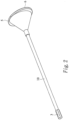
Fig. 8 is a perspective view showing a granule delivery system constructed according to a third preferred embodiment of the present invention. - A granule delivery system (hereinafter abbreviated as GDS) constructed according to a first preferred embodiment of the present invention is shown in
Fig. 1 andFig. 2 , wherein the GDS comprises atube 10 having a major portion having achannel 11 of a uniform circular cross section, afirst rod 5, asecond rod 6 and aperforated cap 3. Thetube 10 has a funnel like proximal end to facilitate the filling of porous granules (not shown inFigs. 1 and2 ) into thechannel 11 thereof. Theperforated cap 3 is used to hold the porous granules having been filled in thechannel 11 of thetube 10, and allows the porous granules to be wet by liquid (e.g. blood) through perforations formed on theperforated cap 3. Therod 5 and therod 6 are identical to each other in this embodiment, each of which has a half circular cross section and a half circular flange at a proximal end thereof, so that they can be joined to form a plunger adapted to be inserted into thetube 10 from the funnel like proximal end thereof by holding the joined half circular flanges. The joined plunger has a cross sectional area about 80-98% of that of thechannel 11 of thetube 10. - In addition to the half circular cross section and the circular cross section used in this embodiment, other shapes are also possible, which are all shown in
Fig. 3 andFig. 4 . A two-step method for delivering the porous granules through thechannel 11 of thetube 10 is developed, which includes (1) inserting thefirst rod 5 into thechannel 11 from the funnel like proximal end and till another end of thetube 10 to push the porous granules which have been filled in saidchannel 11, causing a portion of the porous granules to exit from another end of the tube; (2) removing thefirst rod 5 from thetube 10, joining thefirst rod 5 and thesecond rod 6 to form a plunger, and inserting the plunger (the joinedfirst rod 5 and second rod 6) into thechannel 11 from the funnel like proximal end of thetube 10 to push the porous granules which remain-in thechannel 11 of thetube 10, causing a further portion of the porous granules to exit from the another end of thetube 10. The inserting in the step (2) is stopped when a desired amount of the porous granules exits from the another end of thetube 10, or is all the way till the another end of thetube 10 to empty the tube. Whenever some "resistance" is felt during the step (2) inserting, one can easily go back to the step (1) by pushing only one of the twohalf rods first rod 5 and second rod 6). This "resistance clearing" procedure can be carried out repeatedly until all the remaining porous granules are injected. - In addition to the combination of two half circular cross sections used in the first preferred embodiment of the present invention, it is also possible to use a different combination. As shown in
Fig. 5 , afirst rod 50 has a circular cross section and asecond rod 60 has an annular cross section having a central hole matching the circular cross section of thefirst rod 50, so that thefirst rod 50 and thesecond rod 60 can be joined to form a plunger having a circular cross section. Thefirst rod 50 and thesecond rod 60 shown inFig. 5 can play the same roles as thefirst rod 5 and thesecond rod 6 shown inFig. 1 in the aforesaid two-step method for delivering the porous granules, and the aforesaid "resistance clearing" procedure. - Apparently, the step (2) of the delivery method of the present application can be carried out by using a circular cross sectional plunger corresponding to the joined plunger formed by the first rod 5 (50) and the second rod 6 (60). Alternatively, the circular cross sectional plunger for replacing the joined plunger of the first rod 5 (50) and the second rod 6 (60) in the step (2) may have a cross sectional area which is smaller than that of the joined first rod 5 (50) and second rod 6 (60).
- It is not necessary that the ratio of the cross sectional areas of the first rod to the second rod is about 50% : 50% as shown in
Fig. 3 . Instead of 50% : 50%, the ratio can be, for examples, 20% : 80%, 30% : 70%, 40% : 60%, 60% : 40%, 70% : 30%, or 80% : 20%. It might be also workable in the delivery method of the present application, when the ratio of the cross sectional areas of the first rod to the second rod is 20% : 70%, 30% : 60%, 40% : 50%, 50% : 40%, 60% : 30%, 70% : 20%, or the like. - A GDS constructed according to a second non claimed embodiment is similar to the first preferred embodiment of the present invention except the
first rod 5 and thesecond rod 6 shown inFig. 1 andFig. 2 . In the second preferred embodiment, as shown inFig. 6 to Fig. 7 , afirst rod 500 has a circular cross section having a cross sectional area about 30-60% of that of thechannel 11 of thetube 10, and asecond rod 600 has a circular cross section having a cross sectional area about 80-98% of that of thechannel 11 of thetube 10. The delivery method is carried out by using thefirst rod 500 in the above-mentioned step (1) and using thesecond rod 600 in the above-mentioned step (2). - A GDS constructed according to a third preferred embodiment of the present invention is similar to the first preferred embodiment of the present invention shown in
Fig. 1 andFig. 2 ; however, the distal end of the GDS is curved so that it is adapted to reach a site which cannot be or is difficult to be reached linearly. In the third preferred embodiment, as shown inFig. 8 , the GDS has a tube 10' having acurved section 12 at a distal end thereof; a first rod 5' having a half circular cross section 51 having a cross sectional area about 50% of that of achannel 11 of the tube 10', and athinner section 52 having a reduced cross-sectional area in comparison with that of the section 51; and a second rod 6' identical to the first rod 5'. Thethinner section 52 has a strength enough to allow the first rod 5' to push the porous granules filled in thechannel 11 of the tube 10', and a flexibility to allow a distal end of the first rod 5' to enter thecurved section 12 of the tube 10'. The delivery method of the present invention is carried out by using the first rod 5' in the above-mentioned step (1) and using a joined plunger formed by the first rod 5' and the second rod 6' in the above-mentioned step (2). - Apparently, the step (2) of the delivery method of the present application can be carried out by using a single plunger having a structure corresponding to the joined plunger formed by the first rod 5' and the rod 6'.
- In this example the tubes and the plungers were made of plastic material by rapid prototyping (RP).
- Porous granules having sizes between 0.8 to 0.42 mm filled in a thin tube having a length and an inner diameter as shown in Table 1. The weights of the filled tube and the empty tube were measured, so that the weight of the porous granules filled in the tube could be calculated (W0). The porous granules were then wet with water, and were pushed by a circular plunger having a length longer that of the tube and a diameter matches the inner diameter of the tube. The wet granules exited from the tube were dried by baking, gently broken into granules, and screened to obtain granules having a size less than 0.42 mm, which was weighed (W1). The percentage of (W0-W1)/W0 was calculated and listed in Table 1 as the granule delivery yield.
- Porous granules having sizes between 0.8 to 0.42 mm filled in a thin tube having a length and an inner diameter as shown in Table 1. The weights of the filled tube and the empty tube were measured, so that the weight of the porous granules filled in the tube could be calculated (W0). The porous granules were then wet with water, and were pushed by a first rod, and a second rod after removing the first rod from the tube. The shapes of the cross sections of the first rod and the second rod are both circular; however, the cross sectional area of the first rod is smaller than that of the second rod which has a diameter matching the inner diameter of the tube, as listed in Table 1. The wet granules exited from the tube were dried by baking, gently broken into granules, and screened to obtain granules having a size less than 0.42 mm, which was weighed (W1). The percentage of (W0-W1)/W0 was calculated and listed in Table 1 as the granule delivery yield.
Table 1 Delivery method Tube length (mm) Tube inner dia. (mm) 1st plunger cross-section area (mm2) (1st step insertion) 2nd plunger cross-section area (mm2) (2nd step insertion) Granule delivery yield (%) One step (conventional one plastic plunger 180 5.0 19.6 -- 39 One step (conventional one plastic plunger) 180 4.0 12.6 -- 32 One step (conventional one plastic plunger) 180 3.0 7.1 -- 0 One step (conventional one plastic plunger) 180 2.5 4.9 -- 0 Two-step (two round plastic plungers) 180 3.0 4.9 7.1 10 Two-step (two round plastic plungers) 180 3.0 3.1 7.1 12 Two-step (two round plastic plungers) 180 3.0 0.8 7.1 15 Two-step (two round plastic plungers) 180 2.5 3.1 4.9 23 - The results shown in Table 1 indicate that the conventional one-step method is difficult or impossible to deliver the porous granules through tubes having a length of 180 mm and an inner diameter of 5 mm or less. By using the two-step method with the first thinner plunger and the second matching plunger, it becomes possible to deliver the porous granules through tubes having a length of 180 mm and an inner diameter of 3 mm or 2.5 mm.
- In this example the tubes and the plungers were made of 316 stainless steel.
- Porous granules having sizes between 0.8 to 0.42 mm filled in a thin tube having a length and an inner diameter as shown in Table 2. The weights of the filled tube and the empty tube were measured, so that the weight of the porous granules filled in the tube could be calculated (W0). The porous granules were then wet with water, and were pushed by a first rod (1st plunger). A second rod identical to the first rod was joined with the first rod after removing the first rod from the tube, and then the joined first rod and second rod (2nd plunger) was inserted into the tube to push the porous granules remaining in the tube. The wet granules exited from the tube were dried by baking, gently broken into granules, and screened to obtain granules having a size less than 0.42 mm, which was weighed (W1). The percentage of (W0-W1)/W0 was calculated and listed in Table 2 as the granule delivery yield.
Table 2 Delivery method Tube length (mm) Tube inner dia. (mm) 1st plunger cross-section area (mm2) (1st step insertion) 2nd plunger cross-section area (mm2) 1st plunger/ 2nd plunger combination cross-section area (mm2) (2nd step insertion) Granule delivery yield (%) One-step (conventional one circular steel plunger) 200 3.0 7.1 -- -- 0 One-step (conventional one circular steel plunger) 200 4.0 12.6 -- -- 31.1 One-step (conventional one circular steel plunger) 200 5.0 19.6 -- -- 39.6 Two-step (two semi-circular steel plungers) 200 3.0 3.55 3.55 7.1 63.4 Two-step (two semi-circular steel plungers) 200 4.0 6.3 6.3 12.6 65.7 Two-step (two semi-circular steel plungers) 200 5.0 9.8 9.8 19.6 95.3 - The results shown in Table 1 and Table 2 indicate that the 316 stainless steel can provide a better delivery yield in comparison with the RP plastic material as evidenced by the runs using tubes having an inner diameter of 3 mm. The results in Table 2 also show that the delivery yield is satisfactory by using the two-step method with the two semi-circular rods to deliver the porous granules through tubes having a length of 200 mm and an inner diameter of 3.0 mm, and is as high as 95.3% when the inner diameter is 5.0 mm.
Claims (4)
- An apparatus for delivering particulate material into a bone cavity comprising a tube (10) through which the particulate material is delivered, which comprises a major section having a channel (11) of a uniform circular cross section; a first rod (5); and a second rod (6); wherein the first rod (5) is adapted to be inserted into said channel (11) from one end of said tube (10).
wherein each of the first rod (5) and the second rod (6) has a half circular cross section and a cross sectional area of about 50% of a cross sectional area of said channel (11), so that a combined cross sectional area of the first rod (5) and the second rod (6) is less than and about equal to the cross sectional area of said channel (11), wherein the first rod (5) and the second rod (6) can be joined and joinedly inserted into said channel (11) from said one end of said tube (10) after the first rod (5) being removed from said tube (10). - A system for delivering particulate material comprising said particulate material; and the apparatus of claim 1, wherein the first rod (5) can be inserted into said channel (11) from one end of said tube (10) to push said particulate material filled in said channel (11) in advance, causing a portion of said particulate material exit from another end of said tube (10); and the first rod (5) and the second rod (6) can be joined and joinedly inserted into said channel (11) from said one end of said tube (10) after the first rod (5) being removed from said tube (10), causing a further portion of said particulate material exit from said another end of said tube (10).
- The system of claim 2, wherein said particulate material is porous particulate material.
- The apparatus of claim 1, wherein said major section of said tube (10) is linear with a curved section at another end of said tube (10), said first rod (5) is linear having a uniform cross section with a thinner section between a distal end and a proximal end of said first rod (5), wherein the uniform cross section has said cross sectional area of said first rod, and said thinner section has a smaller cross sectional area compared to the uniform cross section, so that a distal end of the first rod (5) is adapted to be inserted into the curved section at said another end of said tube (10) when said first rod (5) is inserted into said channel (11) from said one end of said tube (10); wherein said second rod (6) is linear having a uniform cross section with a thinner section between a distal end and a proximal end of said second rod (6), wherein the uniform cross section of said second rod (6) has said cross sectional area of said second rod (6), and said thinner section of said second rod (6) has a smaller cross sectional area compared to the uniform cross section of said second rod (6), so that a distal end of the jointed first rod (5) and second rod (6) is adapted to be inserted into the curved section at said another end of said tube (10) when said first rod (5) and said second rod (6) is jointedly inserted into said channel (11) from said one end of said tube (10).
Applications Claiming Priority (2)
| Application Number | Priority Date | Filing Date | Title |
|---|---|---|---|
| US201762451792P | 2017-01-30 | 2017-01-30 | |
| PCT/US2018/014783 WO2018140378A1 (en) | 2017-01-30 | 2018-01-23 | Particulate material delivery system and method |
Publications (3)
| Publication Number | Publication Date |
|---|---|
| EP3554403A1 EP3554403A1 (en) | 2019-10-23 |
| EP3554403A4 EP3554403A4 (en) | 2020-01-08 |
| EP3554403B1 true EP3554403B1 (en) | 2023-07-05 |
Family
ID=62978655
Family Applications (1)
| Application Number | Title | Priority Date | Filing Date |
|---|---|---|---|
| EP18744678.6A Active EP3554403B1 (en) | 2017-01-30 | 2018-01-23 | Particulate material delivery system |
Country Status (5)
| Country | Link |
|---|---|
| US (1) | US11166756B2 (en) |
| EP (1) | EP3554403B1 (en) |
| CN (1) | CN110234287B (en) |
| TW (1) | TWI679040B (en) |
| WO (1) | WO2018140378A1 (en) |
Families Citing this family (2)
| Publication number | Priority date | Publication date | Assignee | Title |
|---|---|---|---|---|
| US11559342B2 (en) * | 2019-05-24 | 2023-01-24 | Joy Medical Devices Corporation | Delivery tool and method for forming a structure having a layer of hardened paste and particles under the layer |
| CN117942456B (en) * | 2024-03-27 | 2024-07-12 | 山东永聚医药科技股份有限公司 | Pre-filled and sealed syringe for slow-release non-Newtonian fluid preparation and preparation process thereof |
Family Cites Families (20)
| Publication number | Priority date | Publication date | Assignee | Title |
|---|---|---|---|---|
| ES2009497A6 (en) | 1987-11-27 | 1989-10-01 | Candela Estruch Miracle | Syringe for one sole use. |
| KR20030029621A (en) | 2000-07-14 | 2003-04-14 | 카이폰 인코포레이티드 | Systems and methods for treating vertebral bodies |
| US20040068234A1 (en) * | 2002-10-03 | 2004-04-08 | Jeff Martin | Bone graft particle delivery apparatus and method |
| US7909833B2 (en) * | 2003-09-29 | 2011-03-22 | Depuy Acromed, Inc. | Vertebroplasty device having a flexible plunger |
| KR100948082B1 (en) | 2005-06-15 | 2010-04-01 | 베절릴 엘엘씨 | Tools and techniques for the continuous delivery of orthopedic pastes |
| WO2008153513A2 (en) * | 2005-09-26 | 2008-12-18 | Isotis Orthobiologics, Inc. | High viscosity material delivery system |
| US9301792B2 (en) * | 2006-01-27 | 2016-04-05 | Stryker Corporation | Low pressure delivery system and method for delivering a solid and liquid mixture into a target site for medical treatment |
| US7905884B2 (en) * | 2006-04-27 | 2011-03-15 | Warsaw Orthopedic, Inc. | Method for use of dilating stylet and cannula |
| US9352137B2 (en) * | 2008-10-29 | 2016-05-31 | Warsaw Orthopedic, Inc. | Drug cartridge for delivering a drug depot comprising a bulking agent and/or cover |
| US8702677B2 (en) * | 2008-10-31 | 2014-04-22 | Warsaw Orthopedic, Inc. | Device and method for directional delivery of a drug depot |
| US8926552B2 (en) | 2009-08-12 | 2015-01-06 | Medtronic, Inc. | Particle delivery |
| JP2013514161A (en) * | 2009-12-17 | 2013-04-25 | ビーエーエスエフ ソシエタス・ヨーロピア | Metal oxide support material containing nanoscale iron-platinum group metal particles |
| US9144190B2 (en) * | 2012-01-23 | 2015-09-29 | Cnh Industrial Canada, Ltd. | Particulate material delivery system for variable rate sectional control |
| GB201209809D0 (en) | 2012-06-01 | 2012-07-18 | Depuy Ireland Ltd | Surgical instrument |
| CN103143104B (en) * | 2013-03-04 | 2015-07-01 | 宁波华科润生物科技有限公司 | Bone filler conveying cannula with adjustable bending angle |
| US9283013B2 (en) * | 2013-03-14 | 2016-03-15 | Warsaw Orthopedic, Inc. | Filling systems for bone delivery devices |
| CN103212148B (en) * | 2013-04-25 | 2015-08-12 | 何凡 | The molten broken bolt conduit of the eccentric sacculus of ilium deep femoral vein thrombosis beading |
| US9504507B2 (en) | 2013-07-05 | 2016-11-29 | Tecres S.P.A. | Injector device for introducing biocompatible material into deep anatomical areas |
| CN107073212B (en) | 2014-07-16 | 2020-01-10 | 捷钛生医股份有限公司 | Pellet transport system and pellet transport method using same |
| CN204410955U (en) * | 2015-01-20 | 2015-06-24 | 昆明医科大学第一附属医院 | Pre-filled device in bone in a kind of kyphoplasty operation |
-
2018
- 2018-01-15 TW TW107101447A patent/TWI679040B/en active
- 2018-01-23 US US16/479,999 patent/US11166756B2/en active Active
- 2018-01-23 CN CN201880006849.6A patent/CN110234287B/en active Active
- 2018-01-23 WO PCT/US2018/014783 patent/WO2018140378A1/en not_active Ceased
- 2018-01-23 EP EP18744678.6A patent/EP3554403B1/en active Active
Also Published As
| Publication number | Publication date |
|---|---|
| TW201827090A (en) | 2018-08-01 |
| US11166756B2 (en) | 2021-11-09 |
| TWI679040B (en) | 2019-12-11 |
| EP3554403A1 (en) | 2019-10-23 |
| EP3554403A4 (en) | 2020-01-08 |
| CN110234287A (en) | 2019-09-13 |
| WO2018140378A1 (en) | 2018-08-02 |
| US20190365446A1 (en) | 2019-12-05 |
| CN110234287B (en) | 2022-05-17 |
Similar Documents
| Publication | Publication Date | Title |
|---|---|---|
| AU782591B2 (en) | Medicinal implant and device and method for loading and delivering implants containing drugs and cells | |
| AU2016201669B2 (en) | Spacer mould and method for producing hip spacers | |
| US10342585B2 (en) | Apparatus for reinforcing bone and tools for mounting the same | |
| US8066760B2 (en) | Stent with movable crown | |
| EP3010575B1 (en) | Medicament applicator | |
| CN107126603B (en) | Plunger with reduced leakage during storage | |
| CN107176390B (en) | Storage and hybrid system and its method for paste cement component | |
| JP2008541836A (en) | Method and apparatus for reducing a stent | |
| US10292749B2 (en) | Cartridge for mixing and injecting bone cement, and bone cement mixing and transferring system including same | |
| JP7289878B2 (en) | Apparatus and method for manufacturing spacers | |
| JP2001520087A (en) | Pre-fillable syringe for automatic dispensing devices | |
| WO2006050445A1 (en) | Cavity filling device | |
| AU1472599A (en) | Device for introducing an endoprosthesis into a catheter shaft | |
| US11166756B2 (en) | Particulate material delivery system and method | |
| JP2010528825A (en) | Syringe assembly including anti-reuse mechanism | |
| JP7531276B2 (en) | Feedback mechanism for an injection device - Patent application | |
| US11491014B2 (en) | Mould for making a temporary prosthetic component for a knee | |
| CN110652383A (en) | Medical instrument, balloon structure and preparation method thereof | |
| US20150157378A1 (en) | Material delivery device | |
| JP6643544B2 (en) | Funnel and extrusion rod for filling aggregate | |
| US20170311998A1 (en) | Device for applying bone replacement pastes | |
| JP2006345975A (en) | Bone filling material | |
| JP2007007028A (en) | Bone prosthesis introduction tool and its operating method |
Legal Events
| Date | Code | Title | Description |
|---|---|---|---|
| STAA | Information on the status of an ep patent application or granted ep patent |
Free format text: STATUS: THE INTERNATIONAL PUBLICATION HAS BEEN MADE |
|
| PUAI | Public reference made under article 153(3) epc to a published international application that has entered the european phase |
Free format text: ORIGINAL CODE: 0009012 |
|
| STAA | Information on the status of an ep patent application or granted ep patent |
Free format text: STATUS: REQUEST FOR EXAMINATION WAS MADE |
|
| 17P | Request for examination filed |
Effective date: 20190719 |
|
| AK | Designated contracting states |
Kind code of ref document: A1 Designated state(s): AL AT BE BG CH CY CZ DE DK EE ES FI FR GB GR HR HU IE IS IT LI LT LU LV MC MK MT NL NO PL PT RO RS SE SI SK SM TR |
|
| AX | Request for extension of the european patent |
Extension state: BA ME |
|
| RAP1 | Party data changed (applicant data changed or rights of an application transferred) |
Owner name: JOY MEDICAL DEVICES CORPORATION |
|
| A4 | Supplementary search report drawn up and despatched |
Effective date: 20191209 |
|
| RIC1 | Information provided on ipc code assigned before grant |
Ipc: A61B 17/88 20060101AFI20191203BHEP Ipc: A61M 31/00 20060101ALI20191203BHEP Ipc: A61M 25/00 20060101ALI20191203BHEP |
|
| DAV | Request for validation of the european patent (deleted) | ||
| DAX | Request for extension of the european patent (deleted) | ||
| STAA | Information on the status of an ep patent application or granted ep patent |
Free format text: STATUS: EXAMINATION IS IN PROGRESS |
|
| 17Q | First examination report despatched |
Effective date: 20220309 |
|
| GRAP | Despatch of communication of intention to grant a patent |
Free format text: ORIGINAL CODE: EPIDOSNIGR1 |
|
| STAA | Information on the status of an ep patent application or granted ep patent |
Free format text: STATUS: GRANT OF PATENT IS INTENDED |
|
| INTG | Intention to grant announced |
Effective date: 20230127 |
|
| GRAS | Grant fee paid |
Free format text: ORIGINAL CODE: EPIDOSNIGR3 |
|
| GRAA | (expected) grant |
Free format text: ORIGINAL CODE: 0009210 |
|
| STAA | Information on the status of an ep patent application or granted ep patent |
Free format text: STATUS: THE PATENT HAS BEEN GRANTED |
|
| P01 | Opt-out of the competence of the unified patent court (upc) registered |
Effective date: 20230505 |
|
| AK | Designated contracting states |
Kind code of ref document: B1 Designated state(s): AL AT BE BG CH CY CZ DE DK EE ES FI FR GB GR HR HU IE IS IT LI LT LU LV MC MK MT NL NO PL PT RO RS SE SI SK SM TR |
|
| REG | Reference to a national code |
Ref country code: CH Ref legal event code: EP |
|
| REG | Reference to a national code |
Ref country code: AT Ref legal event code: REF Ref document number: 1584094 Country of ref document: AT Kind code of ref document: T Effective date: 20230715 |
|
| REG | Reference to a national code |
Ref country code: DE Ref legal event code: R096 Ref document number: 602018052840 Country of ref document: DE |
|
| REG | Reference to a national code |
Ref country code: IE Ref legal event code: FG4D |
|
| REG | Reference to a national code |
Ref country code: LT Ref legal event code: MG9D |
|
| REG | Reference to a national code |
Ref country code: NL Ref legal event code: MP Effective date: 20230705 |
|
| REG | Reference to a national code |
Ref country code: AT Ref legal event code: MK05 Ref document number: 1584094 Country of ref document: AT Kind code of ref document: T Effective date: 20230705 |
|
| PG25 | Lapsed in a contracting state [announced via postgrant information from national office to epo] |
Ref country code: NL Free format text: LAPSE BECAUSE OF FAILURE TO SUBMIT A TRANSLATION OF THE DESCRIPTION OR TO PAY THE FEE WITHIN THE PRESCRIBED TIME-LIMIT Effective date: 20230705 |
|
| PG25 | Lapsed in a contracting state [announced via postgrant information from national office to epo] |
Ref country code: GR Free format text: LAPSE BECAUSE OF FAILURE TO SUBMIT A TRANSLATION OF THE DESCRIPTION OR TO PAY THE FEE WITHIN THE PRESCRIBED TIME-LIMIT Effective date: 20231006 |
|
| PG25 | Lapsed in a contracting state [announced via postgrant information from national office to epo] |
Ref country code: ES Free format text: LAPSE BECAUSE OF FAILURE TO SUBMIT A TRANSLATION OF THE DESCRIPTION OR TO PAY THE FEE WITHIN THE PRESCRIBED TIME-LIMIT Effective date: 20230705 |
|
| PG25 | Lapsed in a contracting state [announced via postgrant information from national office to epo] |
Ref country code: IS Free format text: LAPSE BECAUSE OF FAILURE TO SUBMIT A TRANSLATION OF THE DESCRIPTION OR TO PAY THE FEE WITHIN THE PRESCRIBED TIME-LIMIT Effective date: 20231105 |
|
| PG25 | Lapsed in a contracting state [announced via postgrant information from national office to epo] |
Ref country code: SE Free format text: LAPSE BECAUSE OF FAILURE TO SUBMIT A TRANSLATION OF THE DESCRIPTION OR TO PAY THE FEE WITHIN THE PRESCRIBED TIME-LIMIT Effective date: 20230705 Ref country code: RS Free format text: LAPSE BECAUSE OF FAILURE TO SUBMIT A TRANSLATION OF THE DESCRIPTION OR TO PAY THE FEE WITHIN THE PRESCRIBED TIME-LIMIT Effective date: 20230705 Ref country code: PT Free format text: LAPSE BECAUSE OF FAILURE TO SUBMIT A TRANSLATION OF THE DESCRIPTION OR TO PAY THE FEE WITHIN THE PRESCRIBED TIME-LIMIT Effective date: 20231106 Ref country code: NO Free format text: LAPSE BECAUSE OF FAILURE TO SUBMIT A TRANSLATION OF THE DESCRIPTION OR TO PAY THE FEE WITHIN THE PRESCRIBED TIME-LIMIT Effective date: 20231005 Ref country code: LV Free format text: LAPSE BECAUSE OF FAILURE TO SUBMIT A TRANSLATION OF THE DESCRIPTION OR TO PAY THE FEE WITHIN THE PRESCRIBED TIME-LIMIT Effective date: 20230705 Ref country code: LT Free format text: LAPSE BECAUSE OF FAILURE TO SUBMIT A TRANSLATION OF THE DESCRIPTION OR TO PAY THE FEE WITHIN THE PRESCRIBED TIME-LIMIT Effective date: 20230705 Ref country code: IS Free format text: LAPSE BECAUSE OF FAILURE TO SUBMIT A TRANSLATION OF THE DESCRIPTION OR TO PAY THE FEE WITHIN THE PRESCRIBED TIME-LIMIT Effective date: 20231105 Ref country code: HR Free format text: LAPSE BECAUSE OF FAILURE TO SUBMIT A TRANSLATION OF THE DESCRIPTION OR TO PAY THE FEE WITHIN THE PRESCRIBED TIME-LIMIT Effective date: 20230705 Ref country code: GR Free format text: LAPSE BECAUSE OF FAILURE TO SUBMIT A TRANSLATION OF THE DESCRIPTION OR TO PAY THE FEE WITHIN THE PRESCRIBED TIME-LIMIT Effective date: 20231006 Ref country code: FI Free format text: LAPSE BECAUSE OF FAILURE TO SUBMIT A TRANSLATION OF THE DESCRIPTION OR TO PAY THE FEE WITHIN THE PRESCRIBED TIME-LIMIT Effective date: 20230705 Ref country code: ES Free format text: LAPSE BECAUSE OF FAILURE TO SUBMIT A TRANSLATION OF THE DESCRIPTION OR TO PAY THE FEE WITHIN THE PRESCRIBED TIME-LIMIT Effective date: 20230705 Ref country code: AT Free format text: LAPSE BECAUSE OF FAILURE TO SUBMIT A TRANSLATION OF THE DESCRIPTION OR TO PAY THE FEE WITHIN THE PRESCRIBED TIME-LIMIT Effective date: 20230705 |
|
| PG25 | Lapsed in a contracting state [announced via postgrant information from national office to epo] |
Ref country code: PL Free format text: LAPSE BECAUSE OF FAILURE TO SUBMIT A TRANSLATION OF THE DESCRIPTION OR TO PAY THE FEE WITHIN THE PRESCRIBED TIME-LIMIT Effective date: 20230705 |
|
| REG | Reference to a national code |
Ref country code: DE Ref legal event code: R097 Ref document number: 602018052840 Country of ref document: DE |
|
| PG25 | Lapsed in a contracting state [announced via postgrant information from national office to epo] |
Ref country code: SM Free format text: LAPSE BECAUSE OF FAILURE TO SUBMIT A TRANSLATION OF THE DESCRIPTION OR TO PAY THE FEE WITHIN THE PRESCRIBED TIME-LIMIT Effective date: 20230705 Ref country code: RO Free format text: LAPSE BECAUSE OF FAILURE TO SUBMIT A TRANSLATION OF THE DESCRIPTION OR TO PAY THE FEE WITHIN THE PRESCRIBED TIME-LIMIT Effective date: 20230705 Ref country code: EE Free format text: LAPSE BECAUSE OF FAILURE TO SUBMIT A TRANSLATION OF THE DESCRIPTION OR TO PAY THE FEE WITHIN THE PRESCRIBED TIME-LIMIT Effective date: 20230705 Ref country code: DK Free format text: LAPSE BECAUSE OF FAILURE TO SUBMIT A TRANSLATION OF THE DESCRIPTION OR TO PAY THE FEE WITHIN THE PRESCRIBED TIME-LIMIT Effective date: 20230705 Ref country code: CZ Free format text: LAPSE BECAUSE OF FAILURE TO SUBMIT A TRANSLATION OF THE DESCRIPTION OR TO PAY THE FEE WITHIN THE PRESCRIBED TIME-LIMIT Effective date: 20230705 Ref country code: SK Free format text: LAPSE BECAUSE OF FAILURE TO SUBMIT A TRANSLATION OF THE DESCRIPTION OR TO PAY THE FEE WITHIN THE PRESCRIBED TIME-LIMIT Effective date: 20230705 |
|
| PLBE | No opposition filed within time limit |
Free format text: ORIGINAL CODE: 0009261 |
|
| STAA | Information on the status of an ep patent application or granted ep patent |
Free format text: STATUS: NO OPPOSITION FILED WITHIN TIME LIMIT |
|
| PG25 | Lapsed in a contracting state [announced via postgrant information from national office to epo] |
Ref country code: IT Free format text: LAPSE BECAUSE OF FAILURE TO SUBMIT A TRANSLATION OF THE DESCRIPTION OR TO PAY THE FEE WITHIN THE PRESCRIBED TIME-LIMIT Effective date: 20230705 |
|
| 26N | No opposition filed |
Effective date: 20240408 |
|
| PG25 | Lapsed in a contracting state [announced via postgrant information from national office to epo] |
Ref country code: SI Free format text: LAPSE BECAUSE OF FAILURE TO SUBMIT A TRANSLATION OF THE DESCRIPTION OR TO PAY THE FEE WITHIN THE PRESCRIBED TIME-LIMIT Effective date: 20230705 |
|
| PG25 | Lapsed in a contracting state [announced via postgrant information from national office to epo] |
Ref country code: MC Free format text: LAPSE BECAUSE OF FAILURE TO SUBMIT A TRANSLATION OF THE DESCRIPTION OR TO PAY THE FEE WITHIN THE PRESCRIBED TIME-LIMIT Effective date: 20230705 |
|
| PG25 | Lapsed in a contracting state [announced via postgrant information from national office to epo] |
Ref country code: MC Free format text: LAPSE BECAUSE OF FAILURE TO SUBMIT A TRANSLATION OF THE DESCRIPTION OR TO PAY THE FEE WITHIN THE PRESCRIBED TIME-LIMIT Effective date: 20230705 |
|
| REG | Reference to a national code |
Ref country code: CH Ref legal event code: PL |
|
| PG25 | Lapsed in a contracting state [announced via postgrant information from national office to epo] |
Ref country code: LU Free format text: LAPSE BECAUSE OF NON-PAYMENT OF DUE FEES Effective date: 20240123 |
|
| PG25 | Lapsed in a contracting state [announced via postgrant information from national office to epo] |
Ref country code: LU Free format text: LAPSE BECAUSE OF NON-PAYMENT OF DUE FEES Effective date: 20240123 |
|
| PG25 | Lapsed in a contracting state [announced via postgrant information from national office to epo] |
Ref country code: BE Free format text: LAPSE BECAUSE OF NON-PAYMENT OF DUE FEES Effective date: 20240131 |
|
| PG25 | Lapsed in a contracting state [announced via postgrant information from national office to epo] |
Ref country code: CH Free format text: LAPSE BECAUSE OF NON-PAYMENT OF DUE FEES Effective date: 20240131 |
|
| PG25 | Lapsed in a contracting state [announced via postgrant information from national office to epo] |
Ref country code: CH Free format text: LAPSE BECAUSE OF NON-PAYMENT OF DUE FEES Effective date: 20240131 Ref country code: BE Free format text: LAPSE BECAUSE OF NON-PAYMENT OF DUE FEES Effective date: 20240131 |
|
| REG | Reference to a national code |
Ref country code: BE Ref legal event code: MM Effective date: 20240131 |
|
| PG25 | Lapsed in a contracting state [announced via postgrant information from national office to epo] |
Ref country code: BG Free format text: LAPSE BECAUSE OF FAILURE TO SUBMIT A TRANSLATION OF THE DESCRIPTION OR TO PAY THE FEE WITHIN THE PRESCRIBED TIME-LIMIT Effective date: 20230705 |
|
| PG25 | Lapsed in a contracting state [announced via postgrant information from national office to epo] |
Ref country code: BG Free format text: LAPSE BECAUSE OF FAILURE TO SUBMIT A TRANSLATION OF THE DESCRIPTION OR TO PAY THE FEE WITHIN THE PRESCRIBED TIME-LIMIT Effective date: 20230705 |
|
| PG25 | Lapsed in a contracting state [announced via postgrant information from national office to epo] |
Ref country code: IE Free format text: LAPSE BECAUSE OF NON-PAYMENT OF DUE FEES Effective date: 20240123 |
|
| PG25 | Lapsed in a contracting state [announced via postgrant information from national office to epo] |
Ref country code: IE Free format text: LAPSE BECAUSE OF NON-PAYMENT OF DUE FEES Effective date: 20240123 |
|
| PG25 | Lapsed in a contracting state [announced via postgrant information from national office to epo] |
Ref country code: CY Free format text: LAPSE BECAUSE OF FAILURE TO SUBMIT A TRANSLATION OF THE DESCRIPTION OR TO PAY THE FEE WITHIN THE PRESCRIBED TIME-LIMIT; INVALID AB INITIO Effective date: 20180123 |
|
| PG25 | Lapsed in a contracting state [announced via postgrant information from national office to epo] |
Ref country code: HU Free format text: LAPSE BECAUSE OF FAILURE TO SUBMIT A TRANSLATION OF THE DESCRIPTION OR TO PAY THE FEE WITHIN THE PRESCRIBED TIME-LIMIT; INVALID AB INITIO Effective date: 20180123 |
|
| PG25 | Lapsed in a contracting state [announced via postgrant information from national office to epo] |
Ref country code: TR Free format text: LAPSE BECAUSE OF FAILURE TO SUBMIT A TRANSLATION OF THE DESCRIPTION OR TO PAY THE FEE WITHIN THE PRESCRIBED TIME-LIMIT Effective date: 20230705 |
|
| PGFP | Annual fee paid to national office [announced via postgrant information from national office to epo] |
Ref country code: GB Payment date: 20260121 Year of fee payment: 9 |
|
| PGFP | Annual fee paid to national office [announced via postgrant information from national office to epo] |
Ref country code: DE Payment date: 20260128 Year of fee payment: 9 |
|
| PGFP | Annual fee paid to national office [announced via postgrant information from national office to epo] |
Ref country code: FR Payment date: 20260123 Year of fee payment: 9 |