EP3554370B1 - Control of anatomical image acquisition using physiological information - Google Patents
Control of anatomical image acquisition using physiological information Download PDFInfo
- Publication number
- EP3554370B1 EP3554370B1 EP17818127.7A EP17818127A EP3554370B1 EP 3554370 B1 EP3554370 B1 EP 3554370B1 EP 17818127 A EP17818127 A EP 17818127A EP 3554370 B1 EP3554370 B1 EP 3554370B1
- Authority
- EP
- European Patent Office
- Prior art keywords
- imaging device
- anatomical region
- positioning
- imaging
- anatomical
- Prior art date
- Legal status (The legal status is an assumption and is not a legal conclusion. Google has not performed a legal analysis and makes no representation as to the accuracy of the status listed.)
- Active
Links
- 238000003384 imaging method Methods 0.000 claims description 290
- 210000003484 anatomy Anatomy 0.000 claims description 266
- 238000002604 ultrasonography Methods 0.000 claims description 108
- 230000004962 physiological condition Effects 0.000 claims description 89
- 238000000034 method Methods 0.000 claims description 41
- 230000006872 improvement Effects 0.000 claims description 32
- 230000006866 deterioration Effects 0.000 claims description 29
- 230000001351 cycling effect Effects 0.000 claims description 26
- 238000012544 monitoring process Methods 0.000 claims description 26
- 230000004044 response Effects 0.000 claims description 13
- 239000000523 sample Substances 0.000 description 36
- 230000015654 memory Effects 0.000 description 35
- 210000000115 thoracic cavity Anatomy 0.000 description 16
- 238000004891 communication Methods 0.000 description 11
- 238000005259 measurement Methods 0.000 description 11
- 230000000747 cardiac effect Effects 0.000 description 6
- 239000012530 fluid Substances 0.000 description 6
- 230000003287 optical effect Effects 0.000 description 6
- 210000000056 organ Anatomy 0.000 description 6
- 230000000737 periodic effect Effects 0.000 description 6
- 230000005855 radiation Effects 0.000 description 6
- 238000000605 extraction Methods 0.000 description 5
- 230000008901 benefit Effects 0.000 description 4
- 238000012937 correction Methods 0.000 description 4
- 230000006870 function Effects 0.000 description 4
- 230000001788 irregular Effects 0.000 description 4
- 238000012545 processing Methods 0.000 description 4
- 238000012285 ultrasound imaging Methods 0.000 description 4
- 230000003213 activating effect Effects 0.000 description 3
- 230000003247 decreasing effect Effects 0.000 description 3
- 210000003238 esophagus Anatomy 0.000 description 3
- 239000000284 extract Substances 0.000 description 3
- 230000000004 hemodynamic effect Effects 0.000 description 3
- 230000033001 locomotion Effects 0.000 description 3
- 230000003068 static effect Effects 0.000 description 3
- 230000008878 coupling Effects 0.000 description 2
- 238000010168 coupling process Methods 0.000 description 2
- 238000005859 coupling reaction Methods 0.000 description 2
- 230000002542 deteriorative effect Effects 0.000 description 2
- 238000010586 diagram Methods 0.000 description 2
- 230000008569 process Effects 0.000 description 2
- 239000004065 semiconductor Substances 0.000 description 2
- 210000001519 tissue Anatomy 0.000 description 2
- 230000007704 transition Effects 0.000 description 2
- 238000013519 translation Methods 0.000 description 2
- 230000003187 abdominal effect Effects 0.000 description 1
- 230000006978 adaptation Effects 0.000 description 1
- 238000000418 atomic force spectrum Methods 0.000 description 1
- 230000005540 biological transmission Effects 0.000 description 1
- 210000000988 bone and bone Anatomy 0.000 description 1
- 238000004590 computer program Methods 0.000 description 1
- 238000011156 evaluation Methods 0.000 description 1
- 230000004217 heart function Effects 0.000 description 1
- 230000000977 initiatory effect Effects 0.000 description 1
- 238000003780 insertion Methods 0.000 description 1
- 230000037431 insertion Effects 0.000 description 1
- 238000002608 intravascular ultrasound Methods 0.000 description 1
- 230000007794 irritation Effects 0.000 description 1
- 210000003141 lower extremity Anatomy 0.000 description 1
- 239000011159 matrix material Substances 0.000 description 1
- 238000012986 modification Methods 0.000 description 1
- 230000004048 modification Effects 0.000 description 1
- 210000004197 pelvis Anatomy 0.000 description 1
- 230000002093 peripheral effect Effects 0.000 description 1
- 238000005096 rolling process Methods 0.000 description 1
- 239000007787 solid Substances 0.000 description 1
- 238000013175 transesophageal echocardiography Methods 0.000 description 1
- 210000001364 upper extremity Anatomy 0.000 description 1
Images


Classifications
-
- A—HUMAN NECESSITIES
- A61—MEDICAL OR VETERINARY SCIENCE; HYGIENE
- A61B—DIAGNOSIS; SURGERY; IDENTIFICATION
- A61B6/00—Apparatus for radiation diagnosis, e.g. combined with radiation therapy equipment
- A61B6/54—Control of apparatus or devices for radiation diagnosis
- A61B6/542—Control of apparatus or devices for radiation diagnosis involving control of exposure
-
- A—HUMAN NECESSITIES
- A61—MEDICAL OR VETERINARY SCIENCE; HYGIENE
- A61B—DIAGNOSIS; SURGERY; IDENTIFICATION
- A61B1/00—Instruments for performing medical examinations of the interior of cavities or tubes of the body by visual or photographical inspection, e.g. endoscopes; Illuminating arrangements therefor
- A61B1/00002—Operational features of endoscopes
- A61B1/00004—Operational features of endoscopes characterised by electronic signal processing
- A61B1/00006—Operational features of endoscopes characterised by electronic signal processing of control signals
-
- A—HUMAN NECESSITIES
- A61—MEDICAL OR VETERINARY SCIENCE; HYGIENE
- A61B—DIAGNOSIS; SURGERY; IDENTIFICATION
- A61B1/00—Instruments for performing medical examinations of the interior of cavities or tubes of the body by visual or photographical inspection, e.g. endoscopes; Illuminating arrangements therefor
- A61B1/00002—Operational features of endoscopes
- A61B1/00004—Operational features of endoscopes characterised by electronic signal processing
- A61B1/00009—Operational features of endoscopes characterised by electronic signal processing of image signals during a use of endoscope
- A61B1/000094—Operational features of endoscopes characterised by electronic signal processing of image signals during a use of endoscope extracting biological structures
-
- A—HUMAN NECESSITIES
- A61—MEDICAL OR VETERINARY SCIENCE; HYGIENE
- A61B—DIAGNOSIS; SURGERY; IDENTIFICATION
- A61B1/00—Instruments for performing medical examinations of the interior of cavities or tubes of the body by visual or photographical inspection, e.g. endoscopes; Illuminating arrangements therefor
- A61B1/00147—Holding or positioning arrangements
- A61B1/0016—Holding or positioning arrangements using motor drive units
-
- A—HUMAN NECESSITIES
- A61—MEDICAL OR VETERINARY SCIENCE; HYGIENE
- A61B—DIAGNOSIS; SURGERY; IDENTIFICATION
- A61B5/00—Measuring for diagnostic purposes; Identification of persons
- A61B5/68—Arrangements of detecting, measuring or recording means, e.g. sensors, in relation to patient
- A61B5/6801—Arrangements of detecting, measuring or recording means, e.g. sensors, in relation to patient specially adapted to be attached to or worn on the body surface
- A61B5/6843—Monitoring or controlling sensor contact pressure
-
- A—HUMAN NECESSITIES
- A61—MEDICAL OR VETERINARY SCIENCE; HYGIENE
- A61B—DIAGNOSIS; SURGERY; IDENTIFICATION
- A61B6/00—Apparatus for radiation diagnosis, e.g. combined with radiation therapy equipment
- A61B6/52—Devices using data or image processing specially adapted for radiation diagnosis
- A61B6/5211—Devices using data or image processing specially adapted for radiation diagnosis involving processing of medical diagnostic data
- A61B6/5217—Devices using data or image processing specially adapted for radiation diagnosis involving processing of medical diagnostic data extracting a diagnostic or physiological parameter from medical diagnostic data
-
- A—HUMAN NECESSITIES
- A61—MEDICAL OR VETERINARY SCIENCE; HYGIENE
- A61B—DIAGNOSIS; SURGERY; IDENTIFICATION
- A61B6/00—Apparatus for radiation diagnosis, e.g. combined with radiation therapy equipment
- A61B6/54—Control of apparatus or devices for radiation diagnosis
- A61B6/541—Control of apparatus or devices for radiation diagnosis involving acquisition triggered by a physiological signal
-
- A—HUMAN NECESSITIES
- A61—MEDICAL OR VETERINARY SCIENCE; HYGIENE
- A61B—DIAGNOSIS; SURGERY; IDENTIFICATION
- A61B6/00—Apparatus for radiation diagnosis, e.g. combined with radiation therapy equipment
- A61B6/54—Control of apparatus or devices for radiation diagnosis
- A61B6/548—Remote control of the apparatus or devices
-
- A—HUMAN NECESSITIES
- A61—MEDICAL OR VETERINARY SCIENCE; HYGIENE
- A61B—DIAGNOSIS; SURGERY; IDENTIFICATION
- A61B8/00—Diagnosis using ultrasonic, sonic or infrasonic waves
- A61B8/06—Measuring blood flow
-
- A—HUMAN NECESSITIES
- A61—MEDICAL OR VETERINARY SCIENCE; HYGIENE
- A61B—DIAGNOSIS; SURGERY; IDENTIFICATION
- A61B8/00—Diagnosis using ultrasonic, sonic or infrasonic waves
- A61B8/12—Diagnosis using ultrasonic, sonic or infrasonic waves in body cavities or body tracts, e.g. by using catheters
-
- A—HUMAN NECESSITIES
- A61—MEDICAL OR VETERINARY SCIENCE; HYGIENE
- A61B—DIAGNOSIS; SURGERY; IDENTIFICATION
- A61B8/00—Diagnosis using ultrasonic, sonic or infrasonic waves
- A61B8/42—Details of probe positioning or probe attachment to the patient
-
- A—HUMAN NECESSITIES
- A61—MEDICAL OR VETERINARY SCIENCE; HYGIENE
- A61B—DIAGNOSIS; SURGERY; IDENTIFICATION
- A61B8/00—Diagnosis using ultrasonic, sonic or infrasonic waves
- A61B8/52—Devices using data or image processing specially adapted for diagnosis using ultrasonic, sonic or infrasonic waves
- A61B8/5215—Devices using data or image processing specially adapted for diagnosis using ultrasonic, sonic or infrasonic waves involving processing of medical diagnostic data
- A61B8/5223—Devices using data or image processing specially adapted for diagnosis using ultrasonic, sonic or infrasonic waves involving processing of medical diagnostic data for extracting a diagnostic or physiological parameter from medical diagnostic data
-
- A—HUMAN NECESSITIES
- A61—MEDICAL OR VETERINARY SCIENCE; HYGIENE
- A61B—DIAGNOSIS; SURGERY; IDENTIFICATION
- A61B8/00—Diagnosis using ultrasonic, sonic or infrasonic waves
- A61B8/54—Control of the diagnostic device
- A61B8/543—Control of the diagnostic device involving acquisition triggered by a physiological signal
-
- G—PHYSICS
- G16—INFORMATION AND COMMUNICATION TECHNOLOGY [ICT] SPECIALLY ADAPTED FOR SPECIFIC APPLICATION FIELDS
- G16H—HEALTHCARE INFORMATICS, i.e. INFORMATION AND COMMUNICATION TECHNOLOGY [ICT] SPECIALLY ADAPTED FOR THE HANDLING OR PROCESSING OF MEDICAL OR HEALTHCARE DATA
- G16H50/00—ICT specially adapted for medical diagnosis, medical simulation or medical data mining; ICT specially adapted for detecting, monitoring or modelling epidemics or pandemics
- G16H50/30—ICT specially adapted for medical diagnosis, medical simulation or medical data mining; ICT specially adapted for detecting, monitoring or modelling epidemics or pandemics for calculating health indices; for individual health risk assessment
Landscapes
- Health & Medical Sciences (AREA)
- Life Sciences & Earth Sciences (AREA)
- Engineering & Computer Science (AREA)
- Medical Informatics (AREA)
- Surgery (AREA)
- Public Health (AREA)
- Pathology (AREA)
- Biomedical Technology (AREA)
- General Health & Medical Sciences (AREA)
- Biophysics (AREA)
- Physics & Mathematics (AREA)
- Heart & Thoracic Surgery (AREA)
- Veterinary Medicine (AREA)
- Molecular Biology (AREA)
- Animal Behavior & Ethology (AREA)
- Nuclear Medicine, Radiotherapy & Molecular Imaging (AREA)
- Radiology & Medical Imaging (AREA)
- Optics & Photonics (AREA)
- Physiology (AREA)
- High Energy & Nuclear Physics (AREA)
- Signal Processing (AREA)
- Computer Vision & Pattern Recognition (AREA)
- Data Mining & Analysis (AREA)
- Databases & Information Systems (AREA)
- Epidemiology (AREA)
- Primary Health Care (AREA)
- Hematology (AREA)
- Ultra Sonic Daignosis Equipment (AREA)
- Apparatus For Radiation Diagnosis (AREA)
- Endoscopes (AREA)
Description
- The inventions of the present disclosure generally relate to image device monitoring systems (e.g., Zura-EVO™ 1, CardioQ-EM+ and USCOM®, etc.). The inventions of the present disclosure more particularly relate to improving such image device monitoring systems by providing control of anatomical image acquisition using physiological information (e.g., ejection fraction, cardiac output, IVC/SVC diameter for fluid status, Doppler flow to an organ, etc.).
-
US5906578A describes a method of optimally positioning an imaging device comprising the steps of storing a reference image; continuously obtaining an acquired view with the imaging device; determining whether the imaging device is in an optimal position by periodically comparing the acquired image with the reference image; and adjusting the position of the imaging device if the imaging device is not in an optimal position. - Currently, hemodynamic monitoring as known in the art may involve a continuous ultrasound image acquisition over a specified period of time (e.g., 72 hours) or a fixed periodic ultrasound image acquisition. While advantageous for patient evaluation purposes, there are several drawbacks to such hemodynamic monitoring.
- First, continuous ultrasound acquisition does not comply with an As Low As Reasonably Acceptable (ALARA) clinical practice, which such noncompliance exposes a patient to potential harm during the continuous ultrasound acquisition.
- Second, continuous contact by an ultrasound transducer during a continuous ultrasound acquisition may cause tissue irritation for a patient, especially continuous contact by a Trans-esophageal (TEE) ultrasound probe on an esophagus of the patient for an ultrasound image monitoring of a cardiac function of the patient.
- Third, a fixed periodic ultrasound acquisition with a pre-defined frequency does not adapt to current physiological conditions of the patient and any dynamic changes to such physiological conditions of the patient.
- To improve upon ultrasound monitoring systems, the present disclosure provides inventions for controlling an anatomical image acquisition based on physiological parameters of a patient extracted from an imaging of the patient to thereby minimize a degree of exposure by the patient to the imaging.
- One embodiment of the inventions of the present disclosure is an imaging device positioning system for monitoring an anatomical region.
- The imaging device positioning system employs an imaging device for generating an image of an anatomical region.
- The imaging device positioning system further employs a imaging device controller for controlling a positioning of the imaging device relative to the anatomical region. During a generation by the imaging device of the image of the anatomical region, the imaging device controller adapts the positioning of the imaging device relative to the anatomical region to one or more physiological conditions of the anatomical region extracted from the image of the anatomical region.
- More particularly, the imaging device controller may cyclically adapt the positioning of the imaging device relative to the anatomical region between an imaging position and an non-imaging position based on the physiological condition(s) of the anatomical region extracted from the image of the anatomical region.
- A second embodiment of the inventions of the present disclosure is the imaging device controller employing a physiological condition extractor and a imaging device positioner.
- In operation, a physiological condition extractor generates physiological parameter data informative of the physiological condition(s) of the anatomical region extracted from the image of the anatomical region generated by the imaging device, and the imaging device positioner controls a positioning of the imaging device relative to the anatomical region.
- In response to the physiological parameter data, the imaging device positioner further adapts the positioning of the imaging device relative to the anatomical region to the physiological condition(s) of the anatomical region extracted from the image of the anatomical region.
- A third embodiment of the inventions of the present disclosure an imaging device positioning method of operating the imaging device positioning system for monitoring an anatomical region.
- The imaging device positioning method involves the imaging device generating an image of an anatomical region, and the imaging device controller controlling a positioning of the imaging device relative to the anatomical region.
- The imaging device positioning method further involves the imaging device controller adapts the positioning of the imaging device relative to the anatomical region to the physiological condition(s) of the anatomical region extracted from the image of the anatomical region generated by the imaging device.
- For purposes of describing and claiming the inventions of the present disclosure:
- (1) the term "imaging device" broadly encompasses all imaging devices, as known in the art of the present disclosure and hereinafter conceived, for imaging an anatomical region including, but not limited to:
- (a) an ultrasound transducer of any type including, but not limited to, a Transesophageal echocardiography (TEE) probe, an Intra-cardiac probe (ICE), an intranasal probe, an endobronchial probe, a laparoscopic probe, and an intravascular ultrasound (IVUS) probe;
- (b) an X-ray gantry of any type including, but not limited to, a C-shape X-ray gantry; and
- (c) a flexible or rigid scope of any type, including, but not limited to, an endoscope, an arthroscope, a bronchoscope, a choledochoscope, a colonoscope, a cystoscope, a duodenoscope, a gastroscope, a hysteroscope, a laparoscope, a laryngoscope, a neuroscope, an otoscope, a push enteroscope, a rhinolaryngoscope, a sigmoidoscope, a sinuscope, thorascope, and a nested cannula with imaging capability;
- (2) an adaptation of a positioning of an imaging device relative to the anatomical region to physiological condition(s) of the anatomical region extracted from an image of the anatomical region involves:
- (a) an increase in an imaging of the anatomical region by the imaging device in view of any deterioration of the physiological condition(s) of the anatomical region as delineated in the physiological parameter data; and
- (b) a decrease in an imaging of the anatomical region by the imaging device in view of any improvement of the physiological condition(s) of the anatomical region as delineated in the physiological parameter data;
- (3) the term "physiological condition" broadly encompasses any physiological condition of an anatomical region extractable from an ultrasound image of an anatomical region. A non-limiting example is a physiological condition of a thoracic region including an ejection fraction, a cardiac output, a IVC/SVC diameter for fluid status, and a Doppler flow to an organ;
- (4) the term "imaging positioning" broadly encompasses a designated positioning of an imaging device internal or, in the case of the claimed method, external to an anatomical region whereby an imaging functionality of the imaging device is activated to image the anatomical region as known in the art of the present disclosure;
- (5) the term "non-imaging positioning" broadly encompasses a designated positioning of an imaging device internal or, in the case of the claimed method, external to an anatomical region whereby an imaging functionality of the imaging device is deactivated to image the anatomical region as known in the art of the present disclosure;
- (6) the term "an image device positioning system" broadly encompasses all image device monitoring systems, as known in the art of the present disclosure and hereinafter conceived, incorporating the inventive principles of the present disclosure for visually monitoring an anatomical region. Examples of known image device monitoring systems include, but are not limited to, Zura-EVO™ 1, CardioQ-EM+ and USCOM®;
- (7) the term "image device positioning method" broadly encompasses all image device monitoring methods, as known in the art of the present disclosure and hereinafter conceived, incorporating the inventive principles of the present disclosure for visually monitoring an anatomical region. Examples of known ultrasound monitoring methods include, but are not limited to, the Hemodynamic management (hTEE), Oesophageal Doppler monitoring, and noninvasive ultrasound Doppler monitoring;
- (8) the term "imaging device controller" broadly encompasses all structural configurations of an application specific main board or an application specific integrated circuit housed employed within or linked to an image device positioning system of the present disclosure for controlling an application of various inventive principles of the present disclosure related to an ultrasound imaging of an anatomical region as subsequently exemplarily described herein. The structural configuration of the controller may include, but is not limited to, processor(s), computer-usable/computer readable storage medium(s), an operating system, application module(s), peripheral device controller(s), interface(s), bus(es), slot(s) and port(s);
- (9) the term "application module" broadly encompasses a component of an ultrasound probe controller or a robot controller consisting of an electronic circuit and/or an executable program (e.g., executable software and/or firmware stored on non-transitory computer readable medium(s)) for executing a specific application; and
- (10) the terms "signal", "data", and "command" broadly encompasses all forms of a detectable physical quantity or impulse (e.g., voltage, current, or magnetic field strength) as understood in the art of the present disclosure and as exemplary described herein for communicating information and/or instructions in support of applying various inventive principles of the present disclosure as subsequently described herein. Signal/data/command communication between components of the present disclosure may involve any communication method, as known in the art of the present disclosure and hereinafter conceived, including, but not limited to, signal/data/command transmission/reception over any type of wired or wireless medium/datalink and a reading of signal/data/command uploaded to a computer-usable/computer readable storage medium.
- The foregoing embodiments and other embodiments of the inventions of the present disclosure as well as various features and advantages of the inventions of the present disclosure will become further apparent from the following detailed description of various embodiments of the inventions of the present disclosure read in conjunction with the accompanying drawings. The detailed description and drawings are merely illustrative of the inventions of the present disclosure rather than limiting, the scope of the inventions of the present disclosure being defined by the appended claims and equivalents thereof.
-
-
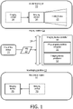
FIG. 1 illustrates an exemplary positioning of an imaging device within an anatomical region in accordance with the inventive principles of the present disclosure. -
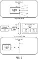
FIG. 2 illustrates an exemplary positioning of an ultrasound transducer within an anatomical region in accordance with the inventive principles of the present disclosure. -
FIG. 3 illustrates an exemplary embodiment of a flowchart representative of an ultrasound positioning method in accordance with the inventive principles of the present disclosure. -
FIGS. 4A and4B illustrates exemplary time varying force control plans in accordance with the inventive principles of the present disclosure. -
FIG. 5 illustrates an exemplary embodiment of an imaging device positioning system incorporating an ultrasound transducer in accordance with the inventive principles of the present disclosure. -
FIG. 6 illustrates an exemplary embodiment of an ultrasound transducer as known in the art. -
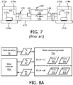
FIG. 7 illustrates an exemplary embodiment of an ultrasound probe robot as known in the art. -
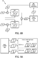
FIGS. 8A and8B illustrates an exemplary embodiment of a sensed force/position control by a motor command generator in accordance with the inventive principles of the present disclosure. -
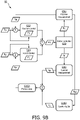
FIGS. 9A and9B illustrates a exemplary embodiment of a sensorless force/position control by a motor command generator in accordance with the inventive principles of the present disclosure. -
FIG. 10 illustrates an exemplary embodiment of the imaging device positioning system ofFIG. 5 in accordance with the inventive principles of the present disclosure. -
FIG. 11 illustrates an exemplary positioning of an X-ray gantry external to an anatomical region in accordance with the inventive principles of the present disclosure. -
FIG. 12 illustrates an exemplary embodiment of an imaging device positioning system incorporating an X-ray gantry in accordance with the inventive principles of the present disclosure. -
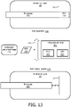
FIG. 13 illustrates an exemplary positioning of a scope external to an anatomical region in accordance with the inventive principles of the present disclosure. -
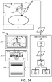
FIG. 14 illustrates an exemplary embodiment of an imaging device positioning system incorporating a scope in accordance with the inventive principles of the present disclosure. - To facilitate an understanding of the inventions of the present disclosure, the following description of
FIG. 1 teaches basic inventive principles of a positioning of an imaging device within an anatomical region in accordance with the inventive principles of the present disclosure. From this description ofFIG. 1 , those having ordinary skill in the art will appreciate how to apply the inventive principles of the present disclosure to practice numerous and various embodiments of positioning of an imaging device internal to or, in the case of the claimed method, external to an anatomical region in accordance with the inventive principles of the present disclosure. - In practice, the inventions of the present disclosure are applicable to any anatomical region including, but not limited to, a cephalic region, a cervical region, a thoracic region, an abdominal region, a pelvic region, a lower extremity and an upper extremity. Also in practice, the inventions of the present disclosure are applicable to any type of anatomical structure including, but not limited to, tissue and bone, healthy or unhealthy.
- Referring to
FIG. 1 , animaging position 12 of the present disclosure encompasses a designated position of animaging device 20 within an anatomical region 10 (e.g., an ultrasound transducer or a scope) whereby an imaging capability ofimaging device 20 is activated for imaging a spatial area and/or of features and structures ofanatomical region 10 within a field ofview 21 ofimaging device 20. Alternatively,imaging positon 12 may encompass a designated position ofimaging device 20 external to anatomical region 10 (e.g., an X-ray gantry) whereby an imaging capability ofimaging device 20 is activated for imaging a spatial area and/or of features and structures ofanatomical region 10 within a field ofview 21 ofimaging device 20. - Conversely, a
non-imaging position 13 of the present disclosure encompasses a designated position of animaging device 20 within an anatomical region 10 (e.g., an ultrasound transducer or a scope) whereby an imaging capability ofimaging device 20 is deactivated for minimizing any contact ofimaging device 20 to a structure ofanatomical region 10 and/or for reducing exposure ofanatomical region 10 to any radiation/energy emitted by imagingdevice 20 for purposes of imaginganatomical region 10. Alternatively,imaging positon 13 may encompass a designated position ofimaging device 20 external to anatomical region 10 (e.g., an X-ray gantry) whereby an imaging capability ofimaging device 20 is deactivated for minimizing any contact ofimaging device 20 to a structure ofanatomical region 10 and/or for reducing exposure ofanatomical region 10 to any radiation/energy emitted by imagingdevice 20 for purposes of imaginganatomical region 10. - Still referring to
FIG. 1 , a periodic orirregular cycling 14 ofimaging device 20 betweenimaging position 12 andnon-imaging position 13 involves a cyclical arrangement ofimaging position 12 andnon-imaging position 13 at a fixed or variable frequency and/or a fixed or variable duty cycle for purposes of visually monitoring a specific aspect ofanatomical region 10 while minimizes anycontact imaging device 20 to a structure ofanatomical region 10 and/or for reducing exposure ofanatomical region 10 to any radiation/energy emitted by imagingdevice 20 for purposes of imaginganatomical region 10. - To this end, an
imaging device controller 30 employs aphysiological condition extractor 31 for extractingphysiological parameter data 22 from ananatomical image 21 of theanatomical region 10 generated by imagingdevice 20 wherebyphysiological parameter data 22 is informative of one or more physiological conditions ofanatomical region 10 as will be further explained herein. For example, ifanatomical region 10 is a thoracic region, then the physiological condition(s) of the thoracic region may be an ejection fraction, a stroke volume, a cardiac output, an IVC/SVC diameter for fluid status and/or a Doppler flow to an organ. - In practice, as would be appreciated by those having ordinary skill in the art of the present disclosure, any extraction technique known in the art may be implemented in dependence upon the type of physiological condition(s) being extracted from
anatomical image 21 of theanatomical region 10. -
Imaging device controller 30 further employs animaging device positioner 32 for controlling an adaption of cycling 14 of a positioning ofimaging device 20 to the physiological condition(s) ofanatomical region 10 extracted fromanatomical image 21 of theanatomical region 10. In practice, the adaption of cycling 14 of a positioning ofimaging device 20 may include an increase to the fixed/variable frequency and/or the fixed/variable duty cycle ofimaging position 12 in view of any deterioration of the physiological condition(s) of the anatomical region as delineated in thephysiological parameter data 22, or conversely a decrease to the fixed/variable frequency and/or the fixed/variable duty cycle ofimaging position 12 in view of any improvement of the physiological condition(s) of the anatomical region as delineated in thephysiological parameter data 22. - Concurrently or alternatively in practice, the adaption of
cycling 14 may include an increase to a degree of contact force betweenimaging device 20 and an anatomical structure ofanatomical region 10 in view of any deterioration of the physiological condition(s) of the anatomical region as delineated in thephysiological parameter data 22 to thereby facilitate a higher quality of imaging ofanatomical region 10, or conversely a decrease to a degree of contact force betweenimaging device 20 and an anatomical structure ofanatomical region 10 in view of any improvement of the physiological condition(s) of the anatomical region as delineated in thephysiological parameter data 22 to thereby facilitates an acceptable quality of imaging ofanatomical region 10 at a lesser degree of contact. - Generally, any deterioration or any improvement of the physiological condition(s) of the anatomical region maybe delineated in the
physiological parameter data 22 by any technique providing a definitive indication of such deterioration or improvement. More particularly in practice, any deterioration or any improvement of the physiological condition(s) of the anatomical region may be delineated by one or more thresholds established relative to thephysiological parameter data 22 as will be further described herein. Concurrently or alternatively in practice, any deterioration or any improvement of the physiological condition(s) of the anatomical region may be delineated by a negative slope or a positive slope of thephysiological parameter data 22 over a specified time period as will be further described herein. - To facilitate a further understanding of the inventions of the present disclosure, the following description of
FIG. 2 teaches basic inventive principles of a positioning of an ultrasound transducer within an anatomical region in accordance with the inventive principles of the present disclosure. From this description ofFIG. 2 , those having ordinary skill in the art will appreciate how to apply the inventive principles of the present disclosure to practice numerous and various embodiments of positioning of an ultrasound transducer internal to or, in the case of the claimed method, external to an anatomical region in accordance with the inventive principles of the present disclosure. - Referring to
FIG. 2 , animaging position 12a of the present disclosure encompasses a positioning within ananatomical region 10 of anultrasound transducer 20a in direct or indirect contact with ananatomical structure 11 wherebyultrasound transducer 20a applies a force/counterforce to theanatomical structure 11 to a degree sufficient to facilitate an ultrasound imaging of theanatomical region 10 as exemplarily symbolized by the bi-directional dashed arrows. - Conversely, a
non-imaging position 13a of the present disclosure encompasses a positioning withinanatomical region 10 ofultrasound transducer 20a in direct or indirect contact withanatomical structure 11 wherebyultrasound transducer 20a is not applying a force/counterforce to theanatomical structure 11 to a degree sufficient to facilitate an ultrasound imaging of the anatomical region 10 (not shown inFIG. 2 ) or encompasses a spatial positioning SP betweenultrasound transducer 20a andanatomical structure 11 as shown inFIG. 2 , and preferably to minimize the force/counterforce imparted on theanatomical structure 11/or reducing the imparted force below a defined threshold. - Still referring to
FIG. 2 , a periodic orirregular cycling 14a ofultrasound transducer 20a betweenimaging position 12a andnon-imaging position 13a involves a cyclical arrangement ofimaging position 12a andnon-imaging position 13a at a fixed or variable frequency and/or a fixed or variable duty cycle for purposes of visually monitoring a specific aspect ofanatomical region 10 while minimizes anycontact ultrasound transducer 20a to a structure ofanatomical region 10 and/or for reducing exposure ofanatomical region 10 to any radiation/energy emitted byultrasound transducer 20a for purposes of imaginganatomical region 10. - To this end, an
ultrasound transducer controller 30a employs aphysiological condition extractor 31a for extractingphysiological parameter data 22a from ananatomical image 21a of theanatomical region 10 generated byultrasound transducer 20a wherebyphysiological parameter data 22a is informative of one or more physiological conditions ofanatomical region 10 as will be further explained herein. For example, ifanatomical region 10 is a thoracic region, then the physiological condition(s) of the thoracic region may be an ejection fraction, a stroke volume, a cardiac output, an IVC/SVC diameter for fluid status and/or a Doppler flow to an organ. - In practice, as would be appreciated by those having ordinary skill in the art of the present disclosure, any extraction technique known in the art may be implemented in dependence upon the type of physiological condition(s) being extracted from
anatomical image 21a of theanatomical region 10. -
Ultrasound transducer controller 30a further employs anultrasound transducer positioner 32a for controlling an adaption ofcycling 14a of a positioning ofultrasound transducer 20a to the physiological condition(s) ofanatomical region 10 extracted fromanatomical image 21a of theanatomical region 10. In practice, the adaption ofcycling 14a of a positioning ofimaging device 20 may include an increase to the fixed/variable frequency and/or the fixed/variable duty cycle ofimaging position 12a in view of any deterioration of the physiological condition(s) of the anatomical region as delineated in thephysiological parameter data 22a, or conversely a decrease to the fixed/variable frequency and/or the fixed/variable duty cycle ofimaging position 12a in view of any improvement of the physiological condition(s) of the anatomical region as delineated in thephysiological parameter data 22a. - Concurrently or alternatively in practice, the adaption of
cycling 14a may include an increase to a degree of contact force betweenultrasound transducer 20a and an anatomical structure ofanatomical region 10 in view of any deterioration of the physiological condition(s) of the anatomical region as delineated in thephysiological parameter data 22a to thereby facilitate a higher quality of imaging ofanatomical region 10, or conversely a decrease to a degree of contact force betweenultrasound transducer 20a and an anatomical structure ofanatomical region 10 in view of any improvement of the physiological condition(s) of the anatomical region as delineated in thephysiological parameter data 22a to thereby facilitates an acceptable quality of imaging ofanatomical region 10 at a lesser degree of contact. - Generally, any deterioration or any improvement of the physiological condition(s) of the anatomical region may be delineated in the
physiological parameter data 22a by any technique providing a definitive indication of such deterioration or improvement as known in the art of the present disclosure. More particularly in practice, any deterioration or any improvement of the physiological condition(s) of the anatomical region may be delineated by one or more thresholds established relative to thephysiological parameter data 22a as will be further described herein. Concurrently or alternatively in practice, any deterioration or any improvement of the physiological condition(s) of the anatomical region may be delineated by a negative slope or a positive slope of thephysiological parameter data 22a over a specified time period as will be further described herein. - To facilitate a further understanding of the inventions of the present disclosure, the following description of
FIGS. 3-4B teaches basic inventive principles of an ultrasound transducer positioning in accordance with the inventive principles of the present disclosure as related tocycling 14a ofimaging position 12a andnon-imaging position 13a as shown inFIG. 2 . From this description ofFIGS. 3-4B , those having ordinary skill in the art will appreciate how to apply the inventive principles of the present disclosure to practice numerous and various embodiments of ultrasound transducer positioning in accordance with the inventive principles of the present disclosure. - Generally in practice, an ultrasound transducer positioning of the present disclosure is based on a devising a base time varying force control plan specifying:
- 1. a base frequency of a forceful positioning of an ultrasound transducer relative to an anatomical structure within an anatomical region;
- 2. a base duty cycle of a forceful positioning and a forceless positioning of the ultrasound transducer relative to an anatomical structure within an anatomical region;
- 3. a desired positioning and a desired contact force associated with the forceful positioning of an ultrasound transducer relative to an anatomical structure within an anatomical region;
- 4. a desired positioning and a desired contact force associated with the forceful positioning of an ultrasound transducer relative to an anatomical structure within an anatomical region;
- 5. one or more physiological condition of the anatomical region to be extracted from the ultrasound image of the anatomical region; and
- 6. a delineation of physiological condition(s) of the anatomical region as a definitive indication of any deterioration or any improvement of the physiological condition(s) of the anatomical region.
- Referring to
FIG. 3 , aflowchart 40 is representative of an ultrasound transducer positioning of the present disclosure. - Referring to
FIGS. 2 and3 ,flowchart 40 is based on a devising of a time varying force control plan specifying a base frequency ofimaging position 12a of anultrasound transducer 20a relative to an anatomical structure within an anatomical region, and a base duty cycle ofimaging position 12a andnon-imaging position 13a. The devising of the time varying force control plan further specifies a desired positioning and a desired contact force for bothimaging position 12a andnon-imaging position 13a as will be further described herein. -
Flowchart 40 will now be described in the context ofimaging position 12a andnon-imaging position 13a ofultrasound transducer 20a in the form a TEE probe relative to an inner surface of an esophagus within a thoracic region, and an extraction of an ejection fraction from an ultrasound image of a heart within thoracic region. From the description offlowchart 40, those having ordinary skill in the art will appreciate how to applyflowchart 40 to other forms of ultrasound transducers relative to any anatomical structure within any anatomical region. - Still referring to
FIGS. 2 and3 , a stage S42 offlowchart 40 encompasses an initiation ofcycling 14a ofimaging position 12a andnon-imaging position 13a, and a stage S44 offlowchart 40 encompasses a measurement of the ejection fraction of the heart within the thoracic region as extracted from the ultrasound image of a heart within thoracic region. - A stage S46 of
flowchart 40 encompasses an adapting ofcycling 14a ofimaging position 12a andnon-imaging position 13a based on the measurement during stage S44 of the ejection fraction of the heart within the thoracic region as extracted from the ultrasound image of a heart within thoracic region. The adaption is in accordance with the time varying force control plan specification a delineation of physiological condition of the ejection fraction of the heart as a definitive indication of any deterioration or any improvement of the ejection fraction of the heart. - Generally in practice, for a definitive indication of any deterioration of the ejection fraction of the heart, the base frequency of
imaging position 12a may be increased as symbolically shown inFIG. 3 and/or the base duty cycle may be increased forimaging position 12a as symbolically shown inFIG. 3 . As a result, the ultrasound monitoring of the ejection fraction of the heart will be increased for diagnostic purposes. - Conversely in practice, for a definitive indication of any improvement of the ejection fraction of the heart, the base frequency of
imaging position 12a may be decreased as symbolically shown inFIG. 3 and/or the base duty cycle may be decreased forimaging position 12a as symbolically shown inFIG. 3 . As a result, the ultrasound monitoring of the ejection fraction of the heart will be decreased for diagnostic purposes. - In one exemplary embodiment of stage S46,
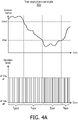
FIG. 4A illustrates a time varyingforce control plan 50a delineating a good threshold and a poor threshold as respective definitive indications of an improving or a deteriorating measurement of ejection fraction of the heart. The time varyingforce control plan 50a further specifies: - 1. a good frequency fgood and associated duty cycle for
imaging position 12a whenever the measurement of the ejection fraction of the heart exceeds the good threshold; - 2. a base frequency fbase and associated duty cycle for
imaging position 12a whenever the measurement of the ejection fraction of the heart is between the good threshold and the poor threshold; and - 3. a poor frequency fbase and associated duty cycle for
imaging position 12a whenever the measurement of the ejection fraction of the heart is below the poor threshold. - As shown in
FIG. 4A , the ejection fraction deteriorates from being good to temporarily being poor before showing an improvement toward being good again. As a result, the operation mode ofcycling 14a is adapted to the measurement trends of the ejection fraction. - In a second exemplary embodiment of stage S46,
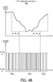
FIG. 4B illustrates a time varyingforce control plan 50b delineating a negative slope and a positive slope over a time period TP threshold as respective definitive indications of an improving or a deteriorating measurement of ejection fraction of the heart. The time varyingforce control plan 50b further specifies: - 1. a transition of a base frequency fbase and associated duty cycle for
imaging position 12a to a poor frequency fbase and associated duty cycle forimaging position 12a whenever the measurement of the ejection fraction of the heart is demonstrating a negative slope over time period TP; and - 2. a transition of poor frequency fbase and associated duty cycle for
imaging position 12a to base frequency fbase and associated duty cycle forimaging position 12a whenever the measurement of the ejection fraction of the heart is demonstrating a positive slope over time period TP; - As shown in
FIG. 4B , again, the ejection fraction deteriorates from being good to temporarily being poor before showing an improvement toward being good again. As a result, the operation mode ofcycling 14a is adapted to the measurement trends of the ejection fraction. - Referring back to
FIGS. 2 and3 , stages S44 and S46 are repeated until such time the ultrasound monitoring of the anatomical region is terminated. Those having ordinary skill in the art of the present disclosure will appreciate the benefit offlowchart 40 in minimizing contact betweenultrasound transducer 20a andanatomical structure 11 and in minimizing ultrasound expose toanatomical region 10. - To facilitate a further understanding of the inventions of the present disclosure, the following description of
FIGS. 5-9B teaches basic inventive principles of an ultrasound transducer positioning system in accordance with the inventive principles of the present disclosure as related tocycling 14a ofimaging position 12a andnon-imaging position 13a as shown inFIG. 2 . From this description ofFIGS. 4-9 , those having ordinary skill in the art will appreciate how to apply the inventive principles of the present disclosure to practice numerous and various embodiments of ultrasound transducer positioning system in accordance with the inventive principles of the present disclosure. - Referring to
FIG. 5 , an ultrasound transducer positioning system of the present disclosure employsultrasound transducer 20a and anultrasound probe robot 60. - In practice,
ultrasound transducer 20a may include any type of transducer array as known in the art of the present disclosure and hereinafter conceived including, but not limited to, a linear array, a phased array, a curvi-linear array and a matrix sensor array. - In one embodiment of
ultrasound transducer 20a,FIG. 6 illustrates aTEE probe 120 as known in the art employing ahandle 121 and an elongated probe having aproximal end 122p attached to handle 121 and adistal head end 122d with anultrasound transducer array 123.TEE probe 120 further employs ayaw actuation dial 124 for adjusting a yaw degree freedom ofultrasound transducer array 123, and apitch actuation dial 125 for adjusting a pitch degree freedom ofultrasound transducer array 123. - Referring back to
FIG. 5 , in practice,ultrasound probe robot 60 may be any type of robot, as known in the art of the present disclosure and hereinafter conceived, employing one or more motor controller(s) 61 for controlling a yawing and/or a pitching of an ultrasound transducer array ofultrasound transducer 20a.Motor controllers 61 may also be utilized to control a rolling and/or a translation of the ultrasound transducer array ofultrasound transducer 20a. - In one embodiment of
ultrasound probe robot 60,FIG. 7 illustrates an ultrasound probe robot including arobotic actuator 160 and anactuator platform 170. -
Robotic actuator 160 employs a probe handle cover 133 having a concave inner surface (not shown) and a probe handle base 135 having a concave inner surface (not shown) for defining a actuation chamber upon being magnetically coupled via one or more magnetic couplers (not shown). In operation, the chamber houses the actuation dials 124 and 125 of TEE probe 120 (FIG. 6 ) and the magnetic coupling provides an advantage of facilitating an easy removal ofTEE probe 120 is desired, particularly if operating circumstance dictate manual control ofTEE probe 120. -
Robotic actuator 160 further employs a motor (not shown) and a motor controller (not shown) yielding motorized gears controllable byultrasound transducer positioner 32a via an electrical coupling ofrobotic controller 60 to the motor controllers. In operation, the motorized gears are sufficient to engage and rotate actuation dials 124 and 125 ofTEE probe 120 for a desired pitching and/or yawing oftransducer array 123. -
Actuator platform 170 provides an additional two (2) degrees for freedom of lateral motion and rotational motion fortransducer array 123, which is capable of being pitched and/or yawed byrobotic actuator 160 as previously described herein. - To this end,
actuator platform 170 employs a pair of rails 171, a pair ofsliders 162, a pair of rotation motors 163, and a crank shaft 1745. By techniques known in the art,sliders 162 are slidably coupled to rails 171 and affixed to rotation motors 163, and crankshaft 175 is rotatably coupled to rotation motors 163. In operation, aultrasound transducer positioner 32a (FIG. 5 ) controls a laterally movement ofcrank shaft 175 via conventional control of a sliding ofsliders 162 along rails 171 and for revolving crankshaft 175 about a rotational axis RA via a control of rotation motors 163 (. In practice, rotation motors 163 may have groves 174 for supporting a portion ofhandle 121 ofTEE probe 120,TEE probe 120 itself, and/or cabling of theTEE probe 120. - Referring back to
FIG. 5 , the ultrasound transducer positioning system of the present disclosure further employsultrasound transducer controller 30a (FIG. 2 ), of whichphysiological condition extractor 31a andultrasound transducer positioner 32a are shown. - In practice,
ultrasound transducer controller 30a may embody any arrangement of hardware, software, firmware and/or electronic circuitry for a positioning ofultrasound transducer 20a internal to or, in the case of the claimed method, external toanatomical region 10. - In one embodiment
ultrasound transducer controller 30a may include a processor, a memory, a user interface, a network interface, and a storage interconnected via one or more system buses. - The processor may be any hardware device, as known in the art of the present disclosure or hereinafter conceived, capable of executing instructions stored in memory or storage or otherwise processing data. In a non-limiting example, the processor may include a microprocessor, field programmable gate array (FPGA), application-specific integrated circuit (ASIC), or other similar devices.
- The memory may include various memories, as known in the art of the present disclosure or hereinafter conceived, including, but not limited to, L1, L2, or L3 cache or system memory. In a non-limiting example, the memory may include static random access memory (SRAM), dynamic RAM (DRAM), flash memory, read only memory (ROM), or other similar memory devices.
- The user interface may include one or more devices, as known in the art of the present disclosure or hereinafter conceived, for enabling communication with a user such as an administrator. In a non-limiting example, the user interface may include a display, a mouse, and a keyboard for receiving user commands. In some embodiments, the user interface may include a command line interface or graphical user interface that may be presented to a remote terminal via the network interface.
- The network interface may include one or more devices, as known in the art of the present disclosure or hereinafter conceived, for enabling communication with other hardware devices. In an non-limiting example, the network interface may include a network interface card (NIC) configured to communicate according to the Ethernet protocol. Additionally, the network interface may implement a TCP/IP stack for communication according to the TCP/IP protocols. Various alternative or additional hardware or configurations for the network interface will be apparent\
- The storage may include one or more machine-readable storage media, as known in the art of the present disclosure or hereinafter conceived, including, but not limited to, read-only memory (ROM), random-access memory (RAM), magnetic disk storage media, optical storage media, flash-memory devices, or similar storage media. In various non-limiting embodiments, the storage may store instructions for execution by the processor or data upon with the processor may operate. For example, the storage may store a base operating system for controlling various basic operations of the hardware. The storage may further store one or
more application modules - More particularly, still referring to
FIG. 5 ,physiological parameter extractor 31a consists of executable software/firmware for generatingphysiological parameter data 22a being informative of one or more physiological conditions of anatomical region 10 (FIG. 2 ) extracted from the ultrasound image of the anatomical region as previously described herein in connection with the description ofFIGS. 2-4B . -
Ultrasound transducer positioner 32a employs routines in the form of aforce control manager 33 and amotor command generator 35. -
Force control manager 33 consists of executable software/firmware for generating an enablesignal 34 for switchingmotor command generator 35 between an ON mode for forceful positioning and an OFF mode for forceful positioning as previously described herein in connection with the description ofFIGS. 2-4B .Force control manager 33 further adapts the generation of enablesignal 34 to the physiological condition(s) of the anatomical region indicated byphysiological parameter data 22a as previously described herein in connection with the description ofFIGS. 2-4B . -
Motor command generator 35 consists of executable software/firmware for generating motor commands 36 for controlling a yawing and/or a pitching of the transducer array by motor controller(s) 61 in accordance within enablesignal 34. - In one embodiment of
motor command generator 35,FIG. 8A illustrates amotor controller 61a communicating aposition signal 62 to amotor command generator 35a with theposition signal 62 being indicative of a yaw position and/or a pitch position of the transducer array (FIG. 5 ). Also shown is onemore force sensors 70 communicating force signal(s) 71 tomotor command generator 35a with eachforce signal 71 being indicative of a contact force betweenultrasound transducer 20a and an anatomical structure of anatomical region 10 (FIG. 2 ). - In practice,
force sensors 70 may be embedded inultrasound transducer 20a and/orultrasound probe robot 60. - Still referring to
FIG. 8A ,motor command generator 35a stores a desiredpositioning 36a and a desiredcontact force 36a of the transducer array applicable to an ON mode of enablesignal 34, and a desiredpositioning 36b and a desiredcontact force 36b of the transducer array applicable to an OFF mode of enablesignal 34. Upon an actuation position calibration and a contract force calibration of the ultrasound transducer array ofultrasound transducer 20a as known in the art of the present disclosure,motor command generator 35a generatesmotor command 36 from an execution of a sensedforce control scheme 80 of a simultaneous actuation position and contact force control as shown inFIG. 8B . - Referring to
FIG. 8B , a generation of motor commands 36 involves an application of contact force correction FC to an actuation position PA in view of minimizing a position error between desired actuation position PD and a measured motor position PM, and a contract force error between contact force correction FC and an sensed contact force FS. - Specifically,
motor controller 61a continually communicates a sensed motor position PS during a stage S86 ofscheme 80 tomotor command generator 35a. In response thereto,motor command generator 35a periodically measures sensed motor positions PS and compares the measured motor positions PM to motor positions associated with a desired actuation position PD of the head ofTEE probe 120 and the resulting position error is an input for position control stage S82 designed to minimize the position error. In practice,motor command generator 35a may execute any control technique(s) as known in the art for minimizing the position error (e.g., a PID control). -
Motor command generator 35a also compares the sensed force signal FS to a desired contact force FD and the resulting contact force error is an input for a force control stage S82 designed to minimize the contact force error. In practice,motor command generator 35a may execute any control technique(s) as known in the art for minimizing the contact force error (e.g., a PID control). - A direct method for generating motor command MC is derived from a model that assumes that contact surface of the transducer array acts as an ideal spring, in which case:

TEE probe 40 if there was no obstacle, and K is elastic constant of the anatomical structure (values known in literature can be used). Since x0 can be known from the kinematic model ofTEE probe 40, there is a direct link between motor commands and the force. Similarly to position control value:
-
Motor command generator 35a will continually loop through the stages ofscheme 80 during the procedure. - In a second embodiment of
motor command generator 35,FIG. 9A illustrates amotor controller 61b communicating aposition signal 62 and a motorcurrent signal 63 to amotor command generator 35b with theposition signal 62 being indicative of a yaw position and/or a pitch position of the transducer array ofultrasound transducer 20a (FIG. 5 ) and motorcurrent signal 63 being indicative of currents applied bymotor controller 61b to motors for the current positioning of the transducer array. - Still referring to
FIG. 9A ,motor command generator 35b also stores desiredpositioning 36a and desiredcontact force 36a of the transducer array applicable to an ON mode of enablesignal 34, and desiredpositioning 36b and desiredcontact force 36b of the transducer array applicable to an OFF mode of enablesignal 34. Upon an actuation position calibration and a contract force calibration of the transducer array as known in the art of the present disclosure,motor command generator 35b generatesmotor command 36 from an execution of a sensedforce control scheme 90 of a simultaneous actuation position and contact force control as shown inFIG. 9B . - Referring to
FIG. 9B , a generation of motor commands 36 involves an application of contact force correction FC to an actuation position PA in view of minimizing a position error between desired actuation position PD and a measured motor position PM, and a contract force error between contact force correction FC and an sensed contact force FS. - Specifically,
motor controller 61b continually communicates a sensed motor position PS during a stage S96 ofscheme 90 tomotor command generator 35b. In response thereto,motor command generator 35b periodically measures sensed motor positions PS and compares the measured motor positions PM to motor positions associated with a desired actuation position PD of the head ofTEE probe 120 and the resulting position error is an input for position control stage S92 designed to minimize the position error. In practice,motor command generator 35b may execute any control technique(s) as known in the art for minimizing the position error (e.g., a PID control). -
Motor command generator 35b also periodically in sync measures sensed motor currents IS and combines the measured sensed motor currents IS to an expected motor currents IE, which is calculated by inputting measured motor positions PM into the lookup table of stage S100 as obtained during a calibrations. The lookup table takes two inputs of position of the two dials and returns two expected current values IE for each degree-of-freedom. During stage S102 expected current values IE and the measured motor current values IM are current fed to force curve (C → F) computed during calibration to estimate an expected contact force FE on the head ofTEE probe 120. -
Motor command generator 35b compares the expected force signal FE to a desired contact force FD and the resulting contact force error is an input for a force control stage S94 designed to minimize the contact force error. In practice,motor command generator 35b may execute any control technique(s) as known in the art for minimizing the contact force error (e.g., a PID control). - Again, a direct method for generating motor command MC is derived from a model that assumes that contact surface of the transducer array acts as an ideal spring, in which case:

TEE probe 40 if there was no obstacle, and K is elastic constant of the anatomical structure (values known in literature can be used). Since x0 can be known from the kinematic model ofTEE probe 40, there is a direct link between motor commands and the force. Similarly to position control value:
-
Motor command generator 35b will continually loop through the stages ofscheme 90 during the procedure. - Referring back to
FIGS. 2 and5 , in practice,ultrasound transducer controller 30a may be structurally implemented as a stand-alone controller or installed within a workstation, tablet, server, etc. - In one embodiment,
FIG. 10 illustrates aworkstation 100 having amonitor 101, akeyboard 102 and acomputer 103 havingultrasound transducer controller 30a installed therein. For this exemplary embodiment,TEE probe 120 is supported byrobotic actuator 160 andactuator platform 170 as previously described herein for insertion of the distal end within an esophagus of a patient P. - In practice,
ultrasound transducer controller 30a may further employ an application for activating and deactivating the imaging capability ofTEE probe 120 as known in the art of the present disclosure or such an application may be separately installed oncomputer 103 or another workstation, tablet, server, etc. - Also in practice,
ultrasound transducer controller 30a may further employ an application for displaying an ultrasound image onmonitor 101 as known in the art of the present disclosure or such an application may be separately installed oncomputer 103 or another workstation, tablet, server, etc. - Further in practice, in lieu of receiving
ultrasound imaging data 23 fromultrasound transducer 30a,ultrasound transducer controller 30a may receive ultrasound display data informative of the display of the ultrasound image onmonitor 101 wherebyultrasound transducer controller 30a extracts the physiological conditions(s) from the ultrasound display data. - To facilitate a further understanding of the inventions of the present disclosure, the following description of
FIGS. 11 and12 teaches basic inventive principles of a positioning of an X-ray gantry encircling an anatomical region in accordance with the inventive principles of the present disclosure. From this description ofFIGS. 11 and12 , those having ordinary skill in the art will appreciate how to apply the inventive principles of the present disclosure to practice numerous and various embodiments of positioning of an X-ray gantry encircling an anatomical region in accordance with the inventive principles of the present disclosure. - Referring to
FIG. 11 , animaging position 12b of the present disclosure encompasses a positioning of anX-ray gantry 20b to encircleanatomical region 10 at an orientation whereby an imagingcapability X-ray gantry 20b as known in the art of the present disclosure is activated as exemplarily symbolized by the dashed lines to generate an X-rayanatomical image 21b. - Conversely, a
non-imaging position 13b of the present disclosure encompasses a positioning ofX-ray gantry 20b whereby the imaging capability ofX-ray gantry 20b is deactivated.Non-imaging position 13b may involve a rotation ofX-ray gantry 20b at an orientation incapable of properly imaginganatomical region 10 and/or a lateral translation to create a spacing SP betweenanatomical region 10 andX-ray gantry 20b. - Still referring to
FIG. 11 , a periodic orirregular cycling 14b ofX-ray gantry 20b betweenimaging position 12b andnon-imaging position 13b involves a cyclical arrangement ofimaging position 12b andnon-imaging position 13b at a fixed or variable frequency and/or a fixed or variable duty cycle for purposes of visually monitoring a specific aspect ofanatomical region 10 while minimizing any exposure ofanatomical region 10 to any radiation/energy emitted byX-ray gantry 20b for purposes of imaginganatomical region 10. - To this end, an
X-ray gantry controller 30b employs aphysiological condition extractor 31b for extractingphysiological parameter data 22b from X-rayanatomical image 21b of theanatomical region 10 generated byX-ray gantry 20b wherebyphysiological parameter data 22b is informative of one or more physiological conditions ofanatomical region 10 as will be further explained herein. For example, ifanatomical region 10 is a thoracic region, then the physiological condition(s) of the thoracic region may be an ejection fraction, a stroke volume, a cardiac output, an IVC/SVC diameter for fluid status and/or a Doppler flow to an organ. - In practice, as would be appreciated by those having ordinary skill in the art of the present disclosure, any extraction technique known in the art may be implemented in dependence upon the type of physiological condition(s) being extracted from X-ray
anatomical image 21b of theanatomical region 10. -
X-ray gantry controller 30b further employs anX-ray gantry positioner 32b for controlling an adaption ofcycling 14b of a positioning ofX-ray gantry 20b to the physiological condition(s) ofanatomical region 10 extracted from X-rayanatomical image 21b of theanatomical region 10. In practice, the adaption ofcycling 14b of a positioning ofX-ray gantry 20b may include an increase to the fixed/variable frequency and/or the fixed/variable duty cycle ofimaging position 12b in view of any deterioration of the physiological condition(s) of the anatomical region as delineated in thephysiological parameter data 22b, or conversely a decrease to the fixed/variable frequency and/or the fixed/variable duty cycle ofimaging position 12b in view of any improvement of the physiological condition(s) of the anatomical region as delineated in thephysiological parameter data 22b. - Generally, any deterioration or any improvement of the physiological condition(s) of the anatomical region maybe delineated in the
physiological parameter data 22b by any technique providing a definitive indication of such deterioration or improvement as known in the art of the present disclosure. More particularly in practice, any deterioration or any improvement of the physiological condition(s) of the anatomical region may be delineated by one or more thresholds established relative to thephysiological parameter data 22b as previously described herein. Concurrently or alternatively in practice, any deterioration or any improvement of the physiological condition(s) of the anatomical region may be delineated by a negative slope or a positive slope of thephysiological parameter data 22b over a specified time period as will be further described herein. - Still referring to
FIG. 11 , in practice,X-ray gantry controller 30b may be structurally implemented as a stand-alone controller or installed within a workstation, tablet, server, etc. - In one embodiment,
FIG. 12 illustrates aworkstation 210 having amonitor 211, akeyboard 212 and acomputer 213 havingX-ray gantry controller 30b installed therein. - In practice,
X-ray gantry controller 30b may embody any arrangement of hardware, software, firmware and/or electronic circuitry for a positioning ofX-ray gantry 20b encirclinganatomical region 10. - In one embodiment
X-ray gantry controller 30b may include a processor, a memory, a user interface, a network interface, and a storage interconnected via one or more system buses. - The processor may be any hardware device, as known in the art of the present disclosure or hereinafter conceived, capable of executing instructions stored in memory or storage or otherwise processing data. In a non-limiting example, the processor may include a microprocessor, field programmable gate array (FPGA), application-specific integrated circuit (ASIC), or other similar devices.
- The memory may include various memories, as known in the art of the present disclosure or hereinafter conceived, including, but not limited to, L1, L2, or L3 cache or system memory. In a non-limiting example, the memory may include static random access memory (SRAM), dynamic RAM (DRAM), flash memory, read only memory (ROM), or other similar memory devices.
- The user interface may include one or more devices, as known in the art of the present disclosure or hereinafter conceived, for enabling communication with a user such as an administrator. In a non-limiting example, the user interface may include a display, a mouse, and a keyboard for receiving user commands. In some embodiments, the user interface may include a command line interface or graphical user interface that may be presented to a remote terminal via the network interface.
- The network interface may include one or more devices, as known in the art of the present disclosure or hereinafter conceived, for enabling communication with other hardware devices. In an non-limiting example, the network interface may include a network interface card (NIC) configured to communicate according to the Ethernet protocol. Additionally, the network interface may implement a TCP/IP stack for communication according to the TCP/IP protocols. Various alternative or additional hardware or configurations for the network interface will be apparent\
- The storage may include one or more machine-readable storage media, as known in the art of the present disclosure or hereinafter conceived, including, but not limited to, read-only memory (ROM), random-access memory (RAM), magnetic disk storage media, optical storage media, flash-memory devices, or similar storage media. In various non-limiting embodiments, the storage may store instructions for execution by the processor or data upon with the processor may operate. For example, the storage may store a base operating system for controlling various basic operations of the hardware. The storage may further store one or
more application modules - More particularly, still referring to
FIG. 12 ,physiological parameter extractor 31b consists of executable software/firmware for generatingphysiological parameter data 22b being informative of one or more physiological conditions of anatomical region 10 (FIG. 2 ) extracted from theX-ray image 21b of theanatomical region 10 as previously described herein in connection with the description ofFIG. 11 . -
X-ray gantry positioner 32b consists of executable software/firmware for adapting acycling 14a ofX-ray gantry 20b betweenimaging position 12b andnon-imaging position 13b to the physiological conditions ofanatomical region 10 extracted from theX-ray image 21b of theanatomical region 10 as previously described herein in connection with the description ofFIG. 11 . - In practice,
X-ray gantry controller 30b may further employ an application for activating and deactivating the imaging capability ofX-ray gantry 20b for generating X-ray imaging data 200 as known in the art of the present disclosure or such an application may be separately installed oncomputer 213 or another workstation, tablet, server, etc. - Also in practice,
X-ray gantry controller 30b may further employ an application for displaying an X-ray image onmonitor 211 as known in the art of the present disclosure or such an application may be separately installed oncomputer 213 or another workstation, tablet, server, etc. - Further in practice, in lieu of receiving X-ray imaging data 220 from
X-ray gantry 20b,X-ray gantry controller 30b may receive X-ray display data informative of the display of the X-ray image onmonitor 213 wherebyphysiological parameter extractor 31b extracts the physiological conditions(s) from the X-ray display data. - To facilitate a further understanding of the inventions of the present disclosure, the following description of
FIGS. 13 and14 teaches basic inventive principles of a positioning of an endoscope inserted through a port into an anatomical region in accordance with the inventive principles of the present disclosure. From this description ofFIGS. 13 and14 , those having ordinary skill in the art will appreciate how to apply the inventive principles of the present disclosure to practice numerous and various embodiments of positioning of an endoscope inserted through a port into an anatomical region in accordance with the inventive principles of the present disclosure. - Referring to
FIG. 13 , animaging position 12c of the present disclosure encompasses a positioning of anendoscope 20c inserted through a port intoanatomical region 10 in direct contact with ananatomical structure 11 whereby an imaging capability ofendoscope 20c as known in the art of the present disclosure is activated as exemplarily symbolized by field ofview 21c to generate an endoscopicanatomical image 21c. - Conversely, a
non-imaging position 13c of the present disclosure encompasses a positioning ofendoscope 20c inserted through a port into whereby the imaging capability ofendoscope 20c is deactivated.Non-imaging position 13c may involve a pivoting ofendoscope 20c away fromanatomical structure 11 withinanatomical region 10 and/or a partial or full withdrawal ofendoscope 20c fromanatomical region 10 to create a spacing SP betweenanatomical structure 11 andendoscope 20c. - Still referring to
FIG. 13 , a periodic orirregular cycling 14c ofendoscope 20c betweenimaging position 12c andnon-imaging position 13c involves a cyclical arrangement ofimaging position 12c andnon-imaging position 13c at a fixed or variable frequency and/or a fixed or variable duty cycle for purposes of visually monitoring a specific aspect ofanatomical region 10 while minimizing contact betweenanatomical structure 11 andendoscope 20c. - To this end, an
endoscope controller 30c employs aphysiological condition extractor 31c for extractingphysiological parameter data 22c from endoscopicanatomical image 21c of theanatomical region 10 generated byendoscope 20c wherebyphysiological parameter data 22c is informative of one or more physiological conditions ofanatomical region 10 as will be further explained herein. For example, ifanatomical region 10 is a thoracic region, then the physiological condition(s) of the thoracic region may be an ejection fraction, a stroke volume, a cardiac output, an IVC/SVC diameter for fluid status and/or a Doppler flow to an organ. - In practice, as would be appreciated by those having ordinary skill in the art of the present disclosure, any extraction technique known in the art may be implemented in dependence upon the type of physiological condition(s) being extracted from endoscopic
anatomical image 21c of theanatomical region 10. -
Endoscope controller 30c further employs anendoscope positioner 32c for controlling an adaption ofcycling 14c of a positioning ofendoscope 20c to the physiological condition(s) ofanatomical region 10 extracted from endoscopicanatomical image 21c of theanatomical region 10. In practice, the adaption ofcycling 14c of a positioning ofendoscope 20c may include an increase to the fixed/variable frequency and/or the fixed/variable duty cycle ofimaging position 12c in view of any deterioration of the physiological condition(s) of the anatomical region as delineated in thephysiological parameter data 22c, or conversely a decrease to the fixed/variable frequency and/or the fixed/variable duty cycle ofimaging position 12c in view of any improvement of the physiological condition(s) of the anatomical region as delineated in thephysiological parameter data 22c. - Concurrently or alternatively in practice, the adaption of
cycling 14a may include an increase to a degree of contact force betweenultrasound transducer 20a and an anatomical structure ofanatomical region 10 in view of any deterioration of the physiological condition(s) of the anatomical region as delineated in thephysiological parameter data 22a to thereby facilitate a higher quality of imaging ofanatomical region 10, or conversely a decrease to a degree of contact force betweenultrasound transducer 20a and an anatomical structure ofanatomical region 10 in view of any improvement of the physiological condition(s) of the anatomical region as delineated in thephysiological parameter data 22a to thereby facilitates an acceptable quality of imaging ofanatomical region 10 at a lesser degree of contact. - Generally, any deterioration or any improvement of the physiological condition(s) of the anatomical region maybe delineated in the
physiological parameter data 22c by any technique providing a definitive indication of such deterioration or improvement as known in the art of the present disclosure. More particularly in practice, any deterioration or any improvement of the physiological condition(s) of the anatomical region may be delineated by one or more thresholds established relative to thephysiological parameter data 22c as previously described herein. Concurrently or alternatively in practice, any deterioration or any improvement of the physiological condition(s) of the anatomical region may be delineated by a negative slope or a positive slope of thephysiological parameter data 22c over a specified time period as will be further described herein. - Still referring to
FIG. 13 , in practice,endoscope controller 30c may be structurally implemented as a stand-alone controller or installed within a workstation, tablet, server, etc. - In one embodiment,
FIG. 14 illustrates aworkstation 320 having amonitor 321, akeyboard 322 and acomputer 323 havingendoscope controller 30c installed therein. - In practice,
endoscope controller 30c may embody any arrangement of hardware, software, firmware and/or electronic circuitry for a positioning ofendoscope 20c through the port intoanatomical region 10. - In one
embodiment endoscope controller 30c may include a processor, a memory, a user interface, a network interface, and a storage interconnected via one or more system buses. - The processor may be any hardware device, as known in the art of the present disclosure or hereinafter conceived, capable of executing instructions stored in memory or storage or otherwise processing data. In a non-limiting example, the processor may include a microprocessor, field programmable gate array (FPGA), application-specific integrated circuit (ASIC), or other similar devices.
- The memory may include various memories, as known in the art of the present disclosure or hereinafter conceived, including, but not limited to, L1, L2, or L3 cache or system memory. In a non-limiting example, the memory may include static random access memory (SRAM), dynamic RAM (DRAM), flash memory, read only memory (ROM), or other similar memory devices.
- The user interface may include one or more devices, as known in the art of the present disclosure or hereinafter conceived, for enabling communication with a user such as an administrator. In a non-limiting example, the user interface may include a display, a mouse, and a keyboard for receiving user commands. In some embodiments, the user interface may include a command line interface or graphical user interface that may be presented to a remote terminal via the network interface.
- The network interface may include one or more devices, as known in the art of the present disclosure or hereinafter conceived, for enabling communication with other hardware devices. In an non-limiting example, the network interface may include a network interface card (NIC) configured to communicate according to the Ethernet protocol. Additionally, the network interface may implement a TCP/IP stack for communication according to the TCP/IP protocols. Various alternative or additional hardware or configurations for the network interface will be apparent\
- The storage may include one or more machine-readable storage media, as known in the art of the present disclosure or hereinafter conceived, including, but not limited to, read-only memory (ROM), random-access memory (RAM), magnetic disk storage media, optical storage media, flash-memory devices, or similar storage media. In various non-limiting embodiments, the storage may store instructions for execution by the processor or data upon with the processor may operate. For example, the storage may store a base operating system for controlling various basic operations of the hardware. The storage may further store one or
more application modules - More particularly, still referring to
FIG. 14 ,physiological parameter extractor 31c consists of executable software/firmware for generatingphysiological parameter data 22c being informative of one or more physiological conditions of anatomical region 10 (FIG. 2 ) extracted from the endoscopicanatomical image 21c of theanatomical region 10 as previously described herein in connection with the description ofFIG. 13 . -
Endoscope positioner 32c consists of executable software/firmware for adapting acycling 14a ofendoscope 20c betweenimaging position 12c andnon-imaging position 13c to the physiological condition(s) ofanatomical region 10 extracted from the endoscopicanatomical image 21c of theanatomical region 10 as previously described herein in connection with the description ofFIG. 13 . - More particularly,
endoscope positioner 32c controls an actuation of anendoscope robot 310 and/orrobot platform 311 as known in the art of the present disclosure to translate, rotate and/or pivotendoscope 20c betweenimaging position 12c andnon-imaging position 13c based on the physiological condition(s) ofanatomical region 10 extracted from the endoscopicanatomical image 21c of theanatomical region 10 - In practice,
endoscope controller 30c may further employ an application for activating and deactivating the imaging capability ofendoscope 20c for generatingendoscope imaging data 300 as known in the art of the present disclosure or such an application may be separately installed oncomputer 213 or another workstation, tablet, server, etc. - Also in practice,
endoscope controller 30c may further employ an application for displaying an endoscopic image onmonitor 32 as known in the art of the present disclosure or such an application may be separately installed oncomputer 323 or another workstation, tablet, server, etc. - Further in practice, in lieu of receiving endoscope imaging data 300from
endoscope 20c,endoscope controller 30c may receive endoscope display data informative of the display of the endoscopic image onmonitor 323 wherebyphysiological parameter extractor 31c extracts the physiological conditions(s) from the endoscope display data. - Referring to
FIGS. 1-14 , those having ordinary skill in the art will appreciate numerous benefits of the present disclosure including, but not limited to, an improvement over ultrasound monitoring systems and methods by the inventions of the present disclosure in providing a controlled ultrasound image acquisition of anatomical region based on physiological parameters extracted from the anatomical images whereby sufficient information about a patient's condition is obtainable without any unnecessary contact between the patient and the imaging device and/or without any excessive exposure of the patient to an imaging radiation/energy projected by the imaging device. - Furthermore, as one having ordinary skill in the art will appreciate in view of the teachings provided herein, features, elements, components, etc. described in the present disclosure/specification and/or depicted in the Figures may be implemented in various combinations of electronic components/circuitry, hardware, executable software and executable firmware and provide functions which may be combined in a single element or multiple elements. For example, the functions of the various features, elements, components, etc. shown/illustrated/depicted in the Figures can be provided through the use of dedicated hardware as well as hardware capable of executing software in association with appropriate software. When provided by a processor, the functions can be provided by a single dedicated processor, by a single shared processor, or by a plurality of individual processors, some of which can be shared and/or multiplexed. Moreover, explicit use of the term "processor" should not be construed to refer exclusively to hardware capable of executing software, and can implicitly include, without limitation, digital signal processor ("DSP") hardware, memory (e.g., read only memory ("ROM") for storing software, random access memory ("RAM"), non-volatile storage, etc.) and virtually any means and/or machine (including hardware, software, firmware, circuitry, combinations thereof, etc.) which is capable of (and/or configurable) to perform and/or control a process.
- Moreover, all statements herein reciting principles, aspects, and embodiments of the invention, as well as specific examples thereof, are intended to encompass both structural and functional equivalents thereof. Additionally, it is intended that such equivalents include both currently known equivalents as well as equivalents developed in the future (e.g., any elements developed that can perform the same or substantially similar function, regardless of structure). Thus, for example, it will be appreciated by one having ordinary skill in the art in view of the teachings provided herein that any block diagrams presented herein can represent conceptual views of illustrative system components and/or circuitry embodying the principles of the invention. Similarly, one having ordinary skill in the art should appreciate in view of the teachings provided herein that any flow charts, flow diagrams and the like can represent various processes which can be substantially represented in computer readable storage media and so executed by a computer, processor or other device with processing capabilities, whether or not such computer or processor is explicitly shown.
- Furthermore, exemplary embodiments of the present disclosure can take the form of a computer program product or application module accessible from a computer-usable and/or computer-readable storage medium providing program code and/or instructions for use by or in connection with, e.g., a computer or any instruction execution system. In accordance with the present disclosure, a computer-usable or computer readable storage medium can be any apparatus that can, e.g., include, store, communicate, propagate or transport the program for use by or in connection with the instruction execution system, apparatus or device. Such exemplary medium can be, e.g., an electronic, magnetic, optical, electromagnetic, infrared or semiconductor system (or apparatus or device) or a propagation medium. Examples of a computer-readable medium include, e.g., a semiconductor or solid state memory, magnetic tape, a removable computer diskette, a random access memory (RAM), a read-only memory (ROM), flash (drive), a rigid magnetic disk and an optical disk. Current examples of optical disks include compact disk - read only memory (CD-ROM), compact disk - read/write (CD-R/W) and DVD. Further, it should be understood that any new computer-readable medium which may hereafter be developed should also be considered as computer-readable medium as may be used or referred to in accordance with exemplary embodiments of the present disclosure and disclosure.
- Having described preferred and exemplary embodiments of novel and inventive imaging device positioning systems and methods, (which embodiments are intended to be illustrative and not limiting), it is noted that modifications and variations can be made by persons having ordinary skill in the art in light of the teachings provided herein, including the Figures. It is therefore to be understood that changes can be made in/to the preferred and exemplary embodiments of the present disclosure which are within the scope of the embodiments disclosed herein.
- Moreover, it is contemplated that related systems incorporating and/or implementing the device or such as may be used/implemented in a device in accordance with the present disclosure are also contemplated and considered to be within the scope of the present disclosure.
Claims (18)
- An imaging device positioning system for monitoring an anatomical region (10), the imaging device positioning system comprising:an imaging device (20) for generating an image (21) of the anatomical region (10); andan imaging device controller (30) structurally configured to control a positioning of the imaging device (20) relative to the anatomical region (10),wherein, in response to a generation by the imaging device (20) of the image (21) of the anatomical region (10), the imaging device controller (30) is structurally configured to adapt the cycling of a positioning of the imaging device (20) relative to the anatomical region (10) between an imaging position and an non-imaging position based on the at least one physiological condition of the anatomical region (10) extracted from the image (21) of the anatomical region (10).
- The imaging device positioning system of claim 1,
wherein the imaging device (20) is one of an ultrasound transducer, a scope and a X-ray gantry. - The imaging device positioning system of claim 1, further comprising:a robot for positioning the imaging device (20) relative to the anatomical region (10),wherein the imaging device controller (30) is structurally configured to control a positioning by the robot of the imaging device (20) relative to the anatomical structure, andwherein, in response to the generation by the imaging device (20) of the image (21) of the anatomical region (10), the imaging device controller (30) adapts the positioning by the robot of the imaging device (20) relative to the anatomical region (10) to the at least one physiological condition of the anatomical region (10) extracted from the image (21) of the anatomical region (10).
- The imaging device positioning system of claim 1,
wherein the imaging device controller (30) is structurally configured to decrease a frequency of the positioning of the imaging device (20) in the imaging position in response to physiological parameter data (22) indicating a delineated improvement in the at least one physiological condition of the anatomical region (10) extracted from the image (21) of the anatomical region (10). - The imaging device positioning system of claim 1,
wherein the imaging device controller (30) is structurally configured to increase a frequency of the positioning of the imaging device (20) in the imaging position in response to physiological parameter data (22) indicating a delineated deterioration in the at least one physiological condition of the anatomical region (10) extracted from the image (21) of the anatomical region (10). - The imaging device positioning system of claim 1,
wherein the imaging device controller (30) is structurally configured to decrease a duty cycle of the positioning of the imaging device (20) in the imaging position in response to physiological parameter data (22) indicating a delineated improvement in the at least one physiological condition of the anatomical region (10) extracted from the image (21) of the anatomical region (10). - The imaging device positioning system of claim 1,
wherein the imaging device controller (30) is structurally configured to increase a duty cycle of the positioning of the imaging device (20) in the imaging position in response to physiological parameter data (22) indicating a delineated deterioration in the at least one physiological condition of the anatomical region (10) extracted from the image (21) of the anatomical region (10). - The imaging device positioning system of claim 1,
wherein the imaging device controller (30) is structurally configured to control a degree of contact force applied by the imaging device (20) to an anatomical structure within the anatomical region (10). - The imaging device positioning system of claim 1,
wherein the imaging device controller (30) is structurally configured to control a degree of contact force applied by the imaging device (20) to an anatomical structure within the anatomical region (10) based on the positioning of the imaging device (20) in the imaging position. - A imaging device controller (30) for an imaging device positioning system including an imaging device (20) for generating an image (21) of an anatomical region (10), the imaging device positioning controller (30) comprising:a physiological condition extractor structurally configured to generate physiological parameter data (22) informative of at least one physiological condition of the anatomical region (10) extracted from an image (21) of the anatomical region (10) generated by the imaging device (20); andan imaging device positioner structurally configured to control a positioning of the imaging device (20) relative to the anatomical region (10),wherein, in response to a generation by the imaging device (20) of the image (21) of the anatomical region (10), the imaging device positioner is structurally configured to adapt the cycling of a positioning of the imaging device (20) relative to the anatomical region (10) between an imaging position and an non-imaging position based on the at least one physiological condition of the anatomical region (10) extracted from the image (21) of the anatomical region (10).
- The imaging device controller (30) of claim 10,wherein the imaging device positioner is structurally configured to control a positioning by a robot of the imaging device (20) relative to anatomical structure, andwherein, in response to a generation by the imaging device (20) of the image (21) of the anatomical region (10), the imaging device positioner is structurally configured to adapt the positioning by the robot of the imaging device (20) relative to the at least one physiological condition of the anatomical region (10) extracted from the image (21) of the anatomical region (10).
- The imaging device controller (30) of claim 10,
wherein the imaging device controller (30) is structurally configured to control a degree of contact force applied by the imaging device (20) to an anatomical structure within the anatomical region (10). - The imaging device controller (30) of claim 10,
wherein the imaging device positioner is further structurally configured to control a degree of contact force applied by the imaging device (20) to an anatomical structure within the anatomical region (10) based on the positioning of the imaging device (20) in the imaging position. - An imaging device positioning method of operating an imaging device positioning system for monitoring an anatomical region (10), the imaging device positioning method comprising:an imaging device (20) generating an image (21) of an anatomical region (10); andan imaging device controller (30) controlling a positioning of the imaging device (20) relative to the anatomical region (10), and wherein the imaging device is external to the anatomical region,wherein, in response to the generation by the imaging device (20) of the image (21) of the anatomical region (10), the imaging device positioner adapts the cycling of a positioning of the imaging device (20) relative to the anatomical region (10) between an imaging position and an non-imaging position based the at least one physiological condition of the anatomical region (10) extracted from the image (21) of the anatomical region (10)..
- The imaging device positioning method of claim 14.wherein the imaging device positioning system further includes a robot;wherein the imaging device positioner controls a positioning by the robot of the imaging device (20) relative to anatomical structure, andwherein, in response to a generation by the imaging device (20) of the image (21) of the anatomical region (10), the imaging device positioner adapts the positioning by the robot of the imaging device (20) relative to the anatomical region (10) to the at least one physiological condition of the anatomical region (10) extracted from the image (21) of the anatomical region (10).
- The imaging device positioning method of claim 14,
wherein the imaging device controller (30) controls a degree of contact force applied by the imaging device (20) to an anatomical structure within the anatomical region (10). - The imaging device positioning method of claim 14,
wherein the imaging device positioner cyclically adapts the positioning of the imaging device (20) relative to the anatomical region (10) between the imaging position and the non-imaging position based the at least one physiological condition of the anatomical region (10) extracted from the image (21) of the anatomical region (10). - The imaging device positioning method of claim 17,
wherein the imaging device positioner controls a degree of contact force applied by the imaging device (20) to an anatomical structure within the anatomical region (10) based on the positioning of the imaging device (20) in the imaging position.
Applications Claiming Priority (2)
| Application Number | Priority Date | Filing Date | Title |
|---|---|---|---|
| US201662436205P | 2016-12-19 | 2016-12-19 | |
| PCT/EP2017/083324 WO2018114811A1 (en) | 2016-12-19 | 2017-12-18 | Control of anatomical image acquisition using physiological information |
Publications (2)
| Publication Number | Publication Date |
|---|---|
| EP3554370A1 EP3554370A1 (en) | 2019-10-23 |
| EP3554370B1 true EP3554370B1 (en) | 2022-09-28 |
Family
ID=60782214
Family Applications (1)
| Application Number | Title | Priority Date | Filing Date |
|---|---|---|---|
| EP17818127.7A Active EP3554370B1 (en) | 2016-12-19 | 2017-12-18 | Control of anatomical image acquisition using physiological information |
Country Status (5)
| Country | Link |
|---|---|
| US (2) | US11653889B2 (en) |
| EP (1) | EP3554370B1 (en) |
| JP (1) | JP7104042B2 (en) |
| CN (1) | CN110087548B (en) |
| WO (1) | WO2018114811A1 (en) |
Families Citing this family (1)
| Publication number | Priority date | Publication date | Assignee | Title |
|---|---|---|---|---|
| JP6859557B2 (en) * | 2018-03-22 | 2021-04-14 | ソニア・セラピューティクス株式会社 | Treatment device |
Family Cites Families (17)
| Publication number | Priority date | Publication date | Assignee | Title |
|---|---|---|---|---|
| US5906578A (en) * | 1997-06-18 | 1999-05-25 | Rajan; Govinda N. | Method and system for probe positioning in transesophageal echocardiography |
| US6425865B1 (en) | 1998-06-12 | 2002-07-30 | The University Of British Columbia | Robotically assisted medical ultrasound |
| US8944070B2 (en) | 1999-04-07 | 2015-02-03 | Intuitive Surgical Operations, Inc. | Non-force reflecting method for providing tool force information to a user of a telesurgical system |
| US6716233B1 (en) * | 1999-06-02 | 2004-04-06 | Power Medical Interventions, Inc. | Electromechanical driver and remote surgical instrument attachment having computer assisted control capabilities |
| JP5260036B2 (en) * | 2007-12-17 | 2013-08-14 | ジーイー・メディカル・システムズ・グローバル・テクノロジー・カンパニー・エルエルシー | X-ray CT system |
| CN102264306A (en) | 2008-12-29 | 2011-11-30 | 皇家飞利浦电子股份有限公司 | Ultrasound imaging system with remote control and method of operation thereof |
| JP4910059B2 (en) | 2010-04-21 | 2012-04-04 | 株式会社東芝 | Signal processing apparatus, signal processing method, and signal reproduction apparatus |
| US20110313280A1 (en) * | 2010-06-16 | 2011-12-22 | Assaf Govari | Optical contact sensing in medical probes |
| KR101761314B1 (en) * | 2010-12-03 | 2017-07-26 | 삼성전자주식회사 | Vital signal measurement and control method thereof |
| JP5959803B2 (en) * | 2011-05-02 | 2016-08-02 | キヤノン株式会社 | Subject information acquisition apparatus and control method thereof |
| US9125612B2 (en) * | 2011-10-31 | 2015-09-08 | Volcano Corporation | Devices, systems, and methods for controlling field of view in imaging systems |
| CN104105455B (en) * | 2011-12-03 | 2017-04-19 | 皇家飞利浦有限公司 | Robotic guidance of ultrasound probe in endoscopic surgery |
| JP6099926B2 (en) * | 2012-10-04 | 2017-03-22 | 東芝メディカルシステムズ株式会社 | Ultrasonic medical apparatus and ultrasonic diagnostic imaging apparatus |
| CN105939648B (en) | 2014-01-24 | 2018-12-07 | 皇家飞利浦有限公司 | For the power control without sensor of transesophageal ultrasonography cardiography probe |
| CN114983479A (en) | 2014-01-24 | 2022-09-02 | 皇家飞利浦有限公司 | Robotic actuator for transesophageal echocardiography probe |
| US11540875B2 (en) * | 2014-07-16 | 2023-01-03 | Microcube, Llc | Minimally invasive access channels into bodily regions |
| ITUB20169976A1 (en) * | 2016-01-14 | 2017-07-14 | Comau Spa | System for robot-assisted control of a transrectal probe, for example for use in performing a prostatic ultrasound |
-
2017
- 2017-12-18 CN CN201780078671.1A patent/CN110087548B/en active Active
- 2017-12-18 JP JP2019532075A patent/JP7104042B2/en active Active
- 2017-12-18 WO PCT/EP2017/083324 patent/WO2018114811A1/en active Application Filing
- 2017-12-18 EP EP17818127.7A patent/EP3554370B1/en active Active
- 2017-12-18 US US16/470,265 patent/US11653889B2/en active Active
-
2023
- 2023-04-13 US US18/134,505 patent/US11918404B2/en active Active
Also Published As
| Publication number | Publication date |
|---|---|
| US20230248330A1 (en) | 2023-08-10 |
| CN110087548B (en) | 2023-06-27 |
| JP2020501720A (en) | 2020-01-23 |
| EP3554370A1 (en) | 2019-10-23 |
| US11918404B2 (en) | 2024-03-05 |
| CN110087548A (en) | 2019-08-02 |
| WO2018114811A1 (en) | 2018-06-28 |
| US20200008651A1 (en) | 2020-01-09 |
| JP7104042B2 (en) | 2022-07-20 |
| US11653889B2 (en) | 2023-05-23 |
Similar Documents
| Publication | Publication Date | Title |
|---|---|---|
| US20220125530A1 (en) | Feedback continuous positioning control of end-effectors | |
| JP7304873B2 (en) | Ultrasound imaging data set acquisition and associated devices, systems, and methods for training neural networks | |
| US20150223782A1 (en) | Ultrasound diagnosis apparatus | |
| US11918404B2 (en) | Control of anatomical image acquisition using physiological information | |
| CN102309342B (en) | Transesophageal echocardiography capsule | |
| JP2001170027A (en) | Method and device for localizing medical instrument | |
| US20200008879A1 (en) | Ultrasound guidance of actuatable medical tool | |
| WO2013088326A2 (en) | Automatic imaging plane selection for echocardiography | |
| JP7407725B2 (en) | Ultrasonic imaging plane alignment guidance for neural networks and related devices, systems, and methods | |
| US20150193931A1 (en) | Image processing apparatus, x-ray diagnosis apparatus, and registration method | |
| JP6620104B2 (en) | Robotic actuator for transesophageal echocardiography probe | |
| JP7401447B2 (en) | Ultrasonic imaging plane alignment using neural networks and related devices, systems, and methods | |
| US20200187898A1 (en) | A laparoscopic adapter, an echocardiography probe and a method for coupling the adapter to the probe | |
| KR20210149112A (en) | Image-Based Probe Positioning | |
| US10531861B2 (en) | Ultrasonic diagnosis apparatus | |
| EP3851053A1 (en) | Ultrasound imaging apparatus | |
| US20150025384A1 (en) | Ultrasound medical apparatus and ultrasound diagnosis apparatus | |
| US20220202442A1 (en) | Computer-assisted needle insertion system and computer-assisted needle insertion method | |
| CN117618025A (en) | Valve real-time motion state characterization system, method, equipment and storage medium | |
| CN112512455A (en) | Optimal imaging viewpoint based on interventional instrument loading |
Legal Events
| Date | Code | Title | Description |
|---|---|---|---|
| STAA | Information on the status of an ep patent application or granted ep patent |
Free format text: STATUS: UNKNOWN |
|
| STAA | Information on the status of an ep patent application or granted ep patent |
Free format text: STATUS: THE INTERNATIONAL PUBLICATION HAS BEEN MADE |
|
| PUAI | Public reference made under article 153(3) epc to a published international application that has entered the european phase |
Free format text: ORIGINAL CODE: 0009012 |
|
| STAA | Information on the status of an ep patent application or granted ep patent |
Free format text: STATUS: REQUEST FOR EXAMINATION WAS MADE |
|
| 17P | Request for examination filed |
Effective date: 20190719 |
|
| AK | Designated contracting states |
Kind code of ref document: A1 Designated state(s): AL AT BE BG CH CY CZ DE DK EE ES FI FR GB GR HR HU IE IS IT LI LT LU LV MC MK MT NL NO PL PT RO RS SE SI SK SM TR |
|
| AX | Request for extension of the european patent |
Extension state: BA ME |
|
| RAP1 | Party data changed (applicant data changed or rights of an application transferred) |
Owner name: KONINKLIJKE PHILIPS N.V. |
|
| DAV | Request for validation of the european patent (deleted) | ||
| DAX | Request for extension of the european patent (deleted) | ||
| GRAP | Despatch of communication of intention to grant a patent |
Free format text: ORIGINAL CODE: EPIDOSNIGR1 |
|
| STAA | Information on the status of an ep patent application or granted ep patent |
Free format text: STATUS: GRANT OF PATENT IS INTENDED |
|
| RIC1 | Information provided on ipc code assigned before grant |
Ipc: A61B 6/00 20060101AFI20220411BHEP |
|
| INTG | Intention to grant announced |
Effective date: 20220503 |
|
| GRAS | Grant fee paid |
Free format text: ORIGINAL CODE: EPIDOSNIGR3 |
|
| GRAA | (expected) grant |
Free format text: ORIGINAL CODE: 0009210 |
|
| STAA | Information on the status of an ep patent application or granted ep patent |
Free format text: STATUS: THE PATENT HAS BEEN GRANTED |
|
| AK | Designated contracting states |
Kind code of ref document: B1 Designated state(s): AL AT BE BG CH CY CZ DE DK EE ES FI FR GB GR HR HU IE IS IT LI LT LU LV MC MK MT NL NO PL PT RO RS SE SI SK SM TR |
|
| REG | Reference to a national code |
Ref country code: GB Ref legal event code: FG4D |
|
| REG | Reference to a national code |
Ref country code: CH Ref legal event code: EP |
|
| REG | Reference to a national code |
Ref country code: AT Ref legal event code: REF Ref document number: 1520721 Country of ref document: AT Kind code of ref document: T Effective date: 20221015 |
|
| REG | Reference to a national code |
Ref country code: DE Ref legal event code: R096 Ref document number: 602017062206 Country of ref document: DE |
|
| REG | Reference to a national code |
Ref country code: IE Ref legal event code: FG4D |
|
| REG | Reference to a national code |
Ref country code: LT Ref legal event code: MG9D |
|
| PG25 | Lapsed in a contracting state [announced via postgrant information from national office to epo] |
Ref country code: SE Free format text: LAPSE BECAUSE OF FAILURE TO SUBMIT A TRANSLATION OF THE DESCRIPTION OR TO PAY THE FEE WITHIN THE PRESCRIBED TIME-LIMIT Effective date: 20220928 Ref country code: RS Free format text: LAPSE BECAUSE OF FAILURE TO SUBMIT A TRANSLATION OF THE DESCRIPTION OR TO PAY THE FEE WITHIN THE PRESCRIBED TIME-LIMIT Effective date: 20220928 Ref country code: NO Free format text: LAPSE BECAUSE OF FAILURE TO SUBMIT A TRANSLATION OF THE DESCRIPTION OR TO PAY THE FEE WITHIN THE PRESCRIBED TIME-LIMIT Effective date: 20221228 Ref country code: LV Free format text: LAPSE BECAUSE OF FAILURE TO SUBMIT A TRANSLATION OF THE DESCRIPTION OR TO PAY THE FEE WITHIN THE PRESCRIBED TIME-LIMIT Effective date: 20220928 Ref country code: LT Free format text: LAPSE BECAUSE OF FAILURE TO SUBMIT A TRANSLATION OF THE DESCRIPTION OR TO PAY THE FEE WITHIN THE PRESCRIBED TIME-LIMIT Effective date: 20220928 Ref country code: FI Free format text: LAPSE BECAUSE OF FAILURE TO SUBMIT A TRANSLATION OF THE DESCRIPTION OR TO PAY THE FEE WITHIN THE PRESCRIBED TIME-LIMIT Effective date: 20220928 |
|
| REG | Reference to a national code |
Ref country code: NL Ref legal event code: MP Effective date: 20220928 |
|
| REG | Reference to a national code |
Ref country code: AT Ref legal event code: MK05 Ref document number: 1520721 Country of ref document: AT Kind code of ref document: T Effective date: 20220928 |
|
| PG25 | Lapsed in a contracting state [announced via postgrant information from national office to epo] |
Ref country code: HR Free format text: LAPSE BECAUSE OF FAILURE TO SUBMIT A TRANSLATION OF THE DESCRIPTION OR TO PAY THE FEE WITHIN THE PRESCRIBED TIME-LIMIT Effective date: 20220928 Ref country code: GR Free format text: LAPSE BECAUSE OF FAILURE TO SUBMIT A TRANSLATION OF THE DESCRIPTION OR TO PAY THE FEE WITHIN THE PRESCRIBED TIME-LIMIT Effective date: 20221229 |
|
| PG25 | Lapsed in a contracting state [announced via postgrant information from national office to epo] |
Ref country code: SM Free format text: LAPSE BECAUSE OF FAILURE TO SUBMIT A TRANSLATION OF THE DESCRIPTION OR TO PAY THE FEE WITHIN THE PRESCRIBED TIME-LIMIT Effective date: 20220928 Ref country code: RO Free format text: LAPSE BECAUSE OF FAILURE TO SUBMIT A TRANSLATION OF THE DESCRIPTION OR TO PAY THE FEE WITHIN THE PRESCRIBED TIME-LIMIT Effective date: 20220928 Ref country code: PT Free format text: LAPSE BECAUSE OF FAILURE TO SUBMIT A TRANSLATION OF THE DESCRIPTION OR TO PAY THE FEE WITHIN THE PRESCRIBED TIME-LIMIT Effective date: 20230130 Ref country code: ES Free format text: LAPSE BECAUSE OF FAILURE TO SUBMIT A TRANSLATION OF THE DESCRIPTION OR TO PAY THE FEE WITHIN THE PRESCRIBED TIME-LIMIT Effective date: 20220928 Ref country code: CZ Free format text: LAPSE BECAUSE OF FAILURE TO SUBMIT A TRANSLATION OF THE DESCRIPTION OR TO PAY THE FEE WITHIN THE PRESCRIBED TIME-LIMIT Effective date: 20220928 Ref country code: AT Free format text: LAPSE BECAUSE OF FAILURE TO SUBMIT A TRANSLATION OF THE DESCRIPTION OR TO PAY THE FEE WITHIN THE PRESCRIBED TIME-LIMIT Effective date: 20220928 |
|
| PG25 | Lapsed in a contracting state [announced via postgrant information from national office to epo] |
Ref country code: SK Free format text: LAPSE BECAUSE OF FAILURE TO SUBMIT A TRANSLATION OF THE DESCRIPTION OR TO PAY THE FEE WITHIN THE PRESCRIBED TIME-LIMIT Effective date: 20220928 Ref country code: PL Free format text: LAPSE BECAUSE OF FAILURE TO SUBMIT A TRANSLATION OF THE DESCRIPTION OR TO PAY THE FEE WITHIN THE PRESCRIBED TIME-LIMIT Effective date: 20220928 Ref country code: IS Free format text: LAPSE BECAUSE OF FAILURE TO SUBMIT A TRANSLATION OF THE DESCRIPTION OR TO PAY THE FEE WITHIN THE PRESCRIBED TIME-LIMIT Effective date: 20230128 Ref country code: EE Free format text: LAPSE BECAUSE OF FAILURE TO SUBMIT A TRANSLATION OF THE DESCRIPTION OR TO PAY THE FEE WITHIN THE PRESCRIBED TIME-LIMIT Effective date: 20220928 |
|
| PGFP | Annual fee paid to national office [announced via postgrant information from national office to epo] |
Ref country code: DE Payment date: 20221227 Year of fee payment: 6 |
|
| REG | Reference to a national code |
Ref country code: DE Ref legal event code: R097 Ref document number: 602017062206 Country of ref document: DE |
|
| PG25 | Lapsed in a contracting state [announced via postgrant information from national office to epo] |
Ref country code: NL Free format text: LAPSE BECAUSE OF FAILURE TO SUBMIT A TRANSLATION OF THE DESCRIPTION OR TO PAY THE FEE WITHIN THE PRESCRIBED TIME-LIMIT Effective date: 20220928 Ref country code: AL Free format text: LAPSE BECAUSE OF FAILURE TO SUBMIT A TRANSLATION OF THE DESCRIPTION OR TO PAY THE FEE WITHIN THE PRESCRIBED TIME-LIMIT Effective date: 20220928 |
|
| PG25 | Lapsed in a contracting state [announced via postgrant information from national office to epo] |
Ref country code: DK Free format text: LAPSE BECAUSE OF FAILURE TO SUBMIT A TRANSLATION OF THE DESCRIPTION OR TO PAY THE FEE WITHIN THE PRESCRIBED TIME-LIMIT Effective date: 20220928 |
|
| REG | Reference to a national code |
Ref country code: CH Ref legal event code: PL |
|
| PLBE | No opposition filed within time limit |
Free format text: ORIGINAL CODE: 0009261 |
|
| STAA | Information on the status of an ep patent application or granted ep patent |
Free format text: STATUS: NO OPPOSITION FILED WITHIN TIME LIMIT |
|
| REG | Reference to a national code |
Ref country code: BE Ref legal event code: MM Effective date: 20221231 |
|
| PG25 | Lapsed in a contracting state [announced via postgrant information from national office to epo] |
Ref country code: LU Free format text: LAPSE BECAUSE OF NON-PAYMENT OF DUE FEES Effective date: 20221218 |
|
| 26N | No opposition filed |
Effective date: 20230629 |
|
| PG25 | Lapsed in a contracting state [announced via postgrant information from national office to epo] |
Ref country code: LI Free format text: LAPSE BECAUSE OF NON-PAYMENT OF DUE FEES Effective date: 20221231 Ref country code: IE Free format text: LAPSE BECAUSE OF NON-PAYMENT OF DUE FEES Effective date: 20221218 Ref country code: CH Free format text: LAPSE BECAUSE OF NON-PAYMENT OF DUE FEES Effective date: 20221231 |
|
| PG25 | Lapsed in a contracting state [announced via postgrant information from national office to epo] |
Ref country code: SI Free format text: LAPSE BECAUSE OF FAILURE TO SUBMIT A TRANSLATION OF THE DESCRIPTION OR TO PAY THE FEE WITHIN THE PRESCRIBED TIME-LIMIT Effective date: 20220928 Ref country code: BE Free format text: LAPSE BECAUSE OF NON-PAYMENT OF DUE FEES Effective date: 20221231 |
|
| PGFP | Annual fee paid to national office [announced via postgrant information from national office to epo] |
Ref country code: GB Payment date: 20231219 Year of fee payment: 7 |
|
| PGFP | Annual fee paid to national office [announced via postgrant information from national office to epo] |
Ref country code: FR Payment date: 20231226 Year of fee payment: 7 |
|
| PG25 | Lapsed in a contracting state [announced via postgrant information from national office to epo] |
Ref country code: HU Free format text: LAPSE BECAUSE OF FAILURE TO SUBMIT A TRANSLATION OF THE DESCRIPTION OR TO PAY THE FEE WITHIN THE PRESCRIBED TIME-LIMIT; INVALID AB INITIO Effective date: 20171218 |
|
| PG25 | Lapsed in a contracting state [announced via postgrant information from national office to epo] |
Ref country code: CY Free format text: LAPSE BECAUSE OF FAILURE TO SUBMIT A TRANSLATION OF THE DESCRIPTION OR TO PAY THE FEE WITHIN THE PRESCRIBED TIME-LIMIT Effective date: 20220928 |
|
| PGFP | Annual fee paid to national office [announced via postgrant information from national office to epo] |
Ref country code: DE Payment date: 20231227 Year of fee payment: 7 |