EP3554169B1 - Verfahren und vorrichtung zur bestimmung der ressource eines steuerungskanals und computerspeichermedium - Google Patents
Verfahren und vorrichtung zur bestimmung der ressource eines steuerungskanals und computerspeichermedium Download PDFInfo
- Publication number
- EP3554169B1 EP3554169B1 EP18852744.4A EP18852744A EP3554169B1 EP 3554169 B1 EP3554169 B1 EP 3554169B1 EP 18852744 A EP18852744 A EP 18852744A EP 3554169 B1 EP3554169 B1 EP 3554169B1
- Authority
- EP
- European Patent Office
- Prior art keywords
- frame
- slot
- serial number
- monitoring window
- mod
- Prior art date
- Legal status (The legal status is an assumption and is not a legal conclusion. Google has not performed a legal analysis and makes no representation as to the accuracy of the status listed.)
- Not-in-force
Links
Images

Classifications
-
- H—ELECTRICITY
- H04—ELECTRIC COMMUNICATION TECHNIQUE
- H04L—TRANSMISSION OF DIGITAL INFORMATION, e.g. TELEGRAPHIC COMMUNICATION
- H04L5/00—Arrangements affording multiple use of the transmission path
- H04L5/003—Arrangements for allocating sub-channels of the transmission path
- H04L5/0053—Allocation of signalling, i.e. of overhead other than pilot signals
-
- H—ELECTRICITY
- H04—ELECTRIC COMMUNICATION TECHNIQUE
- H04L—TRANSMISSION OF DIGITAL INFORMATION, e.g. TELEGRAPHIC COMMUNICATION
- H04L27/00—Modulated-carrier systems
- H04L27/26—Systems using multi-frequency codes
- H04L27/2601—Multicarrier modulation systems
- H04L27/2602—Signal structure
- H04L27/26025—Numerology, i.e. varying one or more of symbol duration, subcarrier spacing, Fourier transform size, sampling rate or down-clocking
-
- H—ELECTRICITY
- H04—ELECTRIC COMMUNICATION TECHNIQUE
- H04L—TRANSMISSION OF DIGITAL INFORMATION, e.g. TELEGRAPHIC COMMUNICATION
- H04L5/00—Arrangements affording multiple use of the transmission path
- H04L5/0091—Signalling for the administration of the divided path, e.g. signalling of configuration information
-
- H—ELECTRICITY
- H04—ELECTRIC COMMUNICATION TECHNIQUE
- H04W—WIRELESS COMMUNICATION NETWORKS
- H04W72/00—Local resource management
- H04W72/20—Control channels or signalling for resource management
- H04W72/23—Control channels or signalling for resource management in the downlink direction of a wireless link, i.e. towards a terminal
Definitions
- the disclosure relates to the technical field of wireless communications, and particularly to a method and device for determining resources for a control channel, and a computer storage medium.
- the features of the preamble of the independent claims are known from "3rd Generation Partnership Project; Technical Specification Group Radio Access Network; NR; Physical layer procedures for control (Release 15)", 3GPP DRAFT, R1-1801293, and “Summary of Offline Discussion on Remaining Minimum System Information", 3GPP DRAFT, R1-1721605.
- a CORESET is defined as a resource set for bearing control information, and a UE detects a physical downlink control channel (PDCCH) in the resource set to obtain scheduling information of a physical downlink shared channel (PDSCH) bearing RMSI.
- PDCH physical downlink control channel
- SSB synchronization signal block
- the resource configuration information of the CORESET includes a frequency-domain position of the PDCCH and a monitoring window of the PDCCH.
- the monitoring window of the PDCCH is determined in the following manner: if a multiplexing manner for the SSB and the CORESET is pattern 1, the UE monitors a Type0-PDCCH common search space in two continuous slots. A serial number of a starting slot in the two continuous slots is n 0 .
- Each SSB of which a serial number is i corresponds to a monitoring window, and a serial number n 0 of a starting slot of the monitoring window is determined by using the following formula: n 0 O ⁇ 2 ⁇ + ⁇ i ⁇ M ⁇ mod N slot frame , ⁇ , where N slot frame , ⁇ is the number of slots in a radio frame, M and O are indicated through the resource configuration information of the CORESET in the PBCH, possible values of O include ⁇ 0, 2, 5, 7 ⁇ in a frequency domain of below 6GHz and include ⁇ 0, 2.5, 5, 7.5 ⁇ in a frequency domain of above 6GHz, possible values of M include ⁇ 1/2, 1, 2 ⁇ , possible values of ⁇ are related to a subcarrier spacing of the PDCCH, and ⁇ ⁇ ⁇ 0,1,2,3 ⁇ .
- a slot in a radio frame may be configured as a downlink slot or an uplink slot, and if the calculated n 0 are distributed in various slots among the radio frames, these slots are required to be configured as downlink slots for transmitting RMSI.
- resources which may be configured as uplink slots are reduced, and there are insufficient uplink resources.
- embodiments of the disclosure provide a method and device for determining resources for a control channel and a computer storage medium.
- the embodiments of the disclosure provide a method for determining resources for a control channel, which may include the following operations.
- the starting slot of the first monitoring window may be located in slots of a first half frame of the radio frame; or, the starting slot of the first monitoring window may be located in slots of a second half frame of the radio frame.
- a serial number of a half frame where the starting slot of the first monitoring window is located may be the same as a serial number of a half frame where the first SSB is located.
- both the half frame where the starting slot of the first monitoring window is located and the half frame where the first SSB is located may be the first half frame.
- both the half frame where the starting slot of the first monitoring window is located and the half frame where the first SSB is located may be the second half frame.
- the method may further include the following operation.
- the first downlink control channel may be configured to schedule a first downlink data channel, and the first downlink data channel may bear RMSI.
- the embodiments of the disclosure provide a method for determining resources for a control channel, which may include the following operations.
- the starting slot of the first monitoring window may be located in slots of a first half frame of the radio frame; or, the starting slot of the first monitoring window may be located in slots of a second half frame of the radio frame.
- a serial number of a half frame where the starting slot of the first monitoring window is located may be the same as a serial number of a half frame where the first SSB is located.
- both the half frame where the starting slot of the first monitoring window is located and the half frame where the first SSB is located may be the first half frame.
- both the half frame where the starting slot of the first monitoring window is located and the half frame where the first SSB is located may be the second half frame.
- the first downlink control channel may be configured to schedule a first downlink data channel, and the first downlink data channel may bear RMSI.
- the embodiments of the disclosure provide a device for determining resources for a control channel, which may include a receiving unit and a determination unit.
- the receiving unit may be configured to receive a first SSB.
- the starting slot of the first monitoring window may be located in slots of a first half frame of the radio frame; or, the starting slot of the first monitoring window may be located in slots of a second half frame of the radio frame.
- a serial number of a half frame where the starting slot of the first monitoring window is located may be the same as a serial number of a half frame where the first SSB is located.
- both the half frame where the starting slot of the first monitoring window is located and the half frame where the first SSB is located may be the first half frame.
- both the half frame where the starting slot of the first monitoring window is located and the half frame where the first SSB is located may be the second half frame.
- the first downlink control channel may be configured to schedule a first downlink data channel, and the first downlink data channel may bear RMSI.
- the embodiments of the disclosure provide a device for determining resources for a control channel, which may include a transmitting unit.
- the starting slot of the first monitoring window may be located in slots of a first half frame of the radio frame; or, the starting slot of the first monitoring window may be located in slots of a second half frame of the radio frame.
- a serial number of a half frame where the starting slot of the first monitoring window is located may be the same as a serial number of a half frame where the first SSB is located.
- both the half frame where the starting slot of the first monitoring window is located and the half frame where the first SSB is located may be the first half frame.
- both the half frame where the starting slot of the first monitoring window is located and the half frame where the first SSB is located may be the second half frame.
- the first downlink control channel may be configured to schedule a first downlink data channel, and the first downlink data channel may bear RMSI.
- the embodiments of the disclosure provide a computer storage medium, in which computer-executable instructions may be stored, the computer-executable instruction being executed by a processor to implement the abovementioned method for determining resources for a control channel.
- a monitoring window of a PDCCH is limited in part of slots of a radio frame (for example, a slot range of a half frame), so that more flexible configuration of uplink slot resources by the network is facilitated, a configuration demand for uplink resources is ensured, and the utilization rate of system resources is increased.
- a frequency band adopted for a 5G system is higher than that for Long Term Evolution (LTE)
- path loss for wireless signal transmission increases and coverage of a wireless signal is reduced.
- LTE Long Term Evolution
- a beam is directional, and a narrow beam may not cover all users in a cell but only cover part of region of the cell.
- the base station may transmit signals through four beams in different directions.
- Beam B2 may not cover UE2 but only cover UE1.
- Beam B4 may not cover UE1 but only cover UE2.
- the common channel and signals for example, Synchronization Signals (SSs) and a broadcast channel, in a 5G NR system are required to cover a whole cell in a multi-beam scanning manner for UE in the cell to receive.
- Multi-beam transmitting of SSs is implemented by defining an SS burst set.
- An SS burst set includes one or more SS bursts, and an SS burst includes one or more SSBs.
- An SSB is configured to bear SSs and broadcast channel of a beam. Therefore, an SS burst set may include SSs of beams with a number the same as that of SSBs in a cell.
- an SSB includes a Primary Synchronization Signal (PSS) in one symbol, a Secondary Synchronization Signal (SSS) in one symbol, and a PBCH in two symbols.
- PSS Primary Synchronization Signal
- SSS Secondary Synchronization Signal
- a period of an SS burst set may be configured, and the SS burst set sent in a period is born in a 5ms time window for transmitting.
- a slot For example, for a 15kHz subcarrier spacing, a slot includes 14 symbols and may bear two SSBs.
- Information about a serial number of an SSB is born in the SSB, and UE recognizes the serial number corresponding to the received SSB through the information.
- the number L of the SSBs is determined according to a frequency band of a system.
- L 64.
- Multi-beam scanning is required by the SS and the PBCH. Furthermore, some other common information, for example, RMSI and paging, is also required to be sent in a multi-beam scanning manner.
- Resource configuration information of an RMSI CORESET includes a frequency-domain position of a PDCCH and a monitoring window of the PDCCH.
- the monitoring window of the RMSI PDCCH is determined in the following manner: if a multiplexing manner for an SSB and the CORESET is pattern 1, UE monitors a type0-PDCCH common search space in two continuous slots. A serial number of a starting slot in the two continuous slots is n 0 .
- Each SSB of which a serial number is i corresponds to a monitoring window, and a serial number n 0 of a starting slot of the monitoring window is determined through the following formula: n 0 O ⁇ 2 ⁇ + ⁇ i ⁇ M ⁇ mod N slot frame , ⁇ , where N slot frame , ⁇ is the number of slots in a radio frame, M and O are indicated through the resource configuration information of the CORESET in a PBCH, a value of O includes ⁇ 0, 2, 5, 7 ⁇ in a frequency domain of below 6GHz and includes ⁇ 0, 2.5, 5, 7.5 ⁇ in a frequency domain of above 6GHz, and a value of M includes ⁇ 1/2, 1, 2 ⁇ .
- Table 1 illustrates parameters of the PDCCH monitoring window of the type0-PDCCH common search space in case that the multiplexing manner for the SSB and the CORESET is pattern 1 and a range of a frequency band is 1
- Table 2 illustrates the parameters of the PDCCH monitoring window of the type0-PDCCH common search space in case that the multiplexing manner for the SSB and the CORESET is 1 and the range of the frequency band is 2.
- a value of ⁇ is related to a subcarrier spacing of the PDCCH, and is determined according to Table 3.
- Table 3 ⁇ ⁇ f 2 ⁇ ⁇ 15 [kHz] Cyclic prefix 0 15 Normal 1 30 Normal 2 60 Normal, Extended 3 120 Normal 4 240 Normal
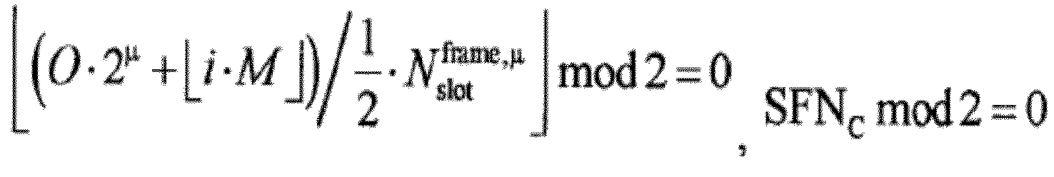
- SFN C when the number, calculated according to ( O ⁇ 2 ⁇ + ⁇ i ⁇ M ⁇ ), of the slots is smaller than the number of the slots in the radio frame, SFN C is an even radio frame; and when it is larger than the number of the slots in the radio frame, SFN C is an odd radio frame.
- FIG. 3 illustrates a first flowchart of a method for determining resources for a control channel according to an embodiment of the disclosure. As illustrated in FIG. 3 , the method for determining resources for a control channel includes the following action.
- N slot frame , ⁇ is the number of the slots in the radio frame.
- M and O are indicated through the resource configuration information of a CORESET in the PBCH.
- a value of O includes ⁇ 0, 2, 5, 7 ⁇ in a frequency domain of below 6GHz and includes ⁇ 0, 2.5, 5, 7.5 ⁇ in a frequency domain of above 6GHz.
- a value of M includes ⁇ 1/2, 1, 2 ⁇ .
- a value of ⁇ is related to a subcarrier spacing of the PDCCH, as illustrated in Table 3.
- a value of HRF is born through the PBCH of the first SSB.
- a serial number of a half frame where the starting slot of the first monitoring window is located are the same as a serial number of a half frame where the first SSB is located.
- both the half frame where the starting slot of the first monitoring window is located and the half frame where the first SSB is located are the first half frame.
- both the half frame where the starting slot of the first monitoring window is located and the half frame where the first SSB is located are the second half frame.
- the first downlink control channel is configured to schedule a first downlink data channel, and the first downlink data channel bears RMSI.
- the terminal After the terminal determines a resource of the first monitoring window, the terminal detects the first downlink control channel in the first monitoring window.
- FIG. 4 illustrates a second flowchart of a method for determining resources for a control channel according to an embodiment of the disclosure. As illustrated in FIG. 4 , the method for determining resources for a control channel includes the following action.
- the value of HRF is born by the PBCH of the first SSB.
- a serial number of a half frame where the starting slot of the first monitoring window is located is the same as a serial number of a half frame where the first SSB is located.
- both the half frame where the starting slot of the first monitoring window is located and the half frame where the first SSB is located are the first half frame.
- both the half frame where the starting slot of the first monitoring window is located and the half frame where the first SSB is located are the second half frame.
- the network device transmits the first downlink control channel in the first monitoring window, and thus the terminal receives the first downlink control channel in the first monitoring window.
- the first downlink control channel is configured to schedule a first downlink data channel, and the first downlink data channel bears RMSI.
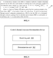
- FIG. 5 illustrates a first structure diagram of a device for determining resources for a control channel according to an embodiment of the disclosure.
- the device for determining resources for a control channel includes a receiving unit 501 and a determination unit 502.
- the receiving unit 501 is configured to receive a first SSB.
- a serial number of a half frame where the starting slot of the first monitoring window is located are the same as a serial number of a half frame where the first SSB is located.
- both the half frame where the starting slot of the first monitoring window is located and the half frame where the first SSB is located are the first half frame.
- both the half frame where the starting slot of the first monitoring window is located and the half frame where the first SSB is located are the second half frame.
- the first downlink control channel is configured to schedule a first downlink data channel, and the first downlink data channel bears RMSI.
- each unit in the device for determining resources for a control channel illustrated in FIG. 5 may be understood with reference to the related descriptions in the abovementioned method for determining resources for a control channel.
- the functions of each unit in the device for determining resources for a control channel illustrated in FIG. 5 may be realized through a program running on a processor, and may also be realized through a specific logical circuit.
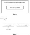
- FIG. 6 illustrates a second structure diagram of a device for determining resources for a control channel according to an embodiment of the disclosure. As illustrated in FIG. 6 , the device for determining resources for a control channel includes a transmitting unit 601.
- a serial number of a half frame where the starting slot of the first monitoring window is located is the same as a serial number of a half frame where the first SSB is located.
- both the half frame where the starting slot of the first monitoring window is located and the half frame where the first SSB is located are the first half frame.
- both the half frame where the starting slot of the first monitoring window is located and the half frame where the first SSB is located are the second half frame.
- the first downlink control channel is configured to schedule a first downlink data channel, and the first downlink data channel bears RMSI.
- each unit in the device for determining resources for a control channel illustrated in FIG. 6 may be understood with reference to the related descriptions in the abovementioned method for determining resources for a control channel.
- the functions of each unit in the device for determining resources for a control channel illustrated in FIG. 6 may be realized through a program running on a processor, and may also be realized through a specific logical circuit.
- the device for determining resources for a control channel of the embodiments of the disclosure may also be stored in a computer-readable storage medium.
- the technical solutions of the embodiments of the disclosure substantially or parts making contributions to the conventional art may be embodied in form of software product, and the computer software product is stored in a storage medium, including a plurality of instructions configured to enable a computer device (which may be a personal computer, a server, a network device or the like) to execute all or part of the method in each embodiment of the disclosure.
- the storage medium includes: various media capable of storing program codes such as a U disk, a mobile hard disk, a Read-Only Memory (ROM), a magnetic disk or an optical disk. Therefore, the embodiments of the disclosure are not limited to any specific hardware and software combination.
- the embodiments of the disclosure also provide a computer storage medium, in which a computer-executable instruction is stored, the computer-executable instruction being executed by a processor to implement the method for determining resources for a control channel of the embodiments of the disclosure.
- FIG. 7 illustrates a structure diagram of a computer device according to an embodiment of the disclosure.
- the computer device may be a terminal and may also be a network device.
- the computer device 100 may include one or more (only one is illustrated in the figure) processors 1002 (the processor 1002 may include, but not limited to, a processing device such as a Micro Control Unit (MCU) or a Field Programmable Gate Array (FPGA)), a memory 1004 configured to store data and a transmission device 1006 configured for a communication function.
- MCU Micro Control Unit
- FPGA Field Programmable Gate Array
- FIG. 7 is only schematic and not intended to limit the structure of the electronic device.
- the computer device 100 may further include components more or fewer than the components illustrated in FIG. 7 or has a configuration different from that illustrated in FIG. 7 .
- the memory 1004 may be configured to store a software program of application software and a module, for example, a program instruction/module corresponding to a method in the embodiments of the disclosure.
- the processor 1002 runs the software program and module stored in the memory 1004, thereby executing various functional applications and data processing, namely implementing the abovementioned method.
- the memory 1004 may include a high-speed random access memory and may also include a nonvolatile memory, for example, one or more magnetic storage devices, flash memories or other nonvolatile solid-state memories.
- the memory 1004 may further include a memory arranged remotely relative to the processor 1002 and the remote memory may be connected to the computer device 100 through a network.
- An example of the network includes, but not limited to, the Internet, an intranet, a local area network, a mobile communication network and a combination thereof.
- the transmission device 1006 is configured to receive or transmit data through a network.
- a specific example of the network may include a wireless network provided by a communication provider of the computer device 100.
- the transmission device 1006 includes a Network Interface Controller (NIC), which may be connected with another network device through a base station, thereby communicating with the Internet.
- the transmission device 1006 may be a Radio Frequency (RF) module, configured to communicate with the Internet in a wireless manner.
- NIC Network Interface Controller
- RF Radio Frequency
- the disclosed method and intelligent device may be implemented in another manner.
- the device embodiment described above is only schematic, and for example, division of the units is only logic function division, and other division manners may be adopted during practical implementation. For example, multiple units or components may be combined or integrated into another system, or some characteristics may be neglected or not executed.
- coupling or direct coupling or communication connection between each displayed or discussed component may be indirect coupling or communication connection, implemented through some interfaces, of the device or the units, and may be electrical and mechanical or adopt other forms.
- the units described as separate parts may or may not be physically separated, and parts displayed as units may or may not be physical units, and namely may be located in the same place, or may also be distributed to multiple network units. Part of all of the units may be selected according to a practical requirement to achieve the purposes of the solutions of the embodiments.
- each functional unit in each embodiment of the disclosure may be integrated into a second processing unit, each unit may also serve as an independent unit and two or more than two units may also be integrated into a unit.
- the integrated unit may be implemented in a hardware form and may also be implemented in form of hardware and software functional unit.
Landscapes
- Engineering & Computer Science (AREA)
- Signal Processing (AREA)
- Computer Networks & Wireless Communication (AREA)
- Physics & Mathematics (AREA)
- Mathematical Physics (AREA)
- Mobile Radio Communication Systems (AREA)
Claims (9)
- Verfahren (301) zum Bestimmen von Ressourcen für einen Steuerkanal, umfassend:Empfangen, durch ein Endgerät, eines ersten Synchronisationssignalblocks, SSB, undBestimmen, durch das Endgerät, auf Basis des ersten SSB, dass eine Seriennummer eines Startschlitzes eines ersten Überwachungsfensters eines ersten Downlink-Steuerkanals in einem Radio Frame lautet:


 wobei, falls die Seriennummer des Startschlitzes des ersten Überwachungsfensters in dem Radio Frame
 wobei, falls die Seriennummer des Startschlitzes des ersten Überwachungsfensters in dem Radio Frame
ist, eine Seriennummer eines Halbframes, wo sich der Startschlitz des ersten Überwachungsfensters befindet, die gleiche ist wie eine Seriennummer eines Halbframes, wo sich der erste SSB befindet; wenn HRF einen ersten Halbframe anzeigt, sowohl der Halbframe, wo sich der Startschlitz des ersten Überwachungsfensters befindet, als auch der Halbframe, wo sich der erste SSB befindet, der erste Halbframe sind; oder wenn HRF einen zweiten Halbframe anzeigt, sowohl der Halbframe, wo sich der Startschlitz des ersten Überwachungsfensters befindet, als auch der Halbframe, wo sich der erste SSB befindet, der zweite Halbframe sind. - Verfahren nach Anspruch 1, weiter umfassend:
Bestimmen, durch das Endgerät, einer Seriennummer des Radio Frame, wo sich der Startschlitz des ersten Überwachungsfensters befindet, auf die folgende Weise:wenn wennwobei SFNC die Seriennummer des Radio Frame ist, wo sich der Startschlitz des ersten Überwachungsfensters befindet.
- Verfahren nach einem der Ansprüche 1-2, wobei der erste Downlink-Steuerkanal konfiguriert ist zum Planen eines ersten Downlink-Datenkanals und Remaining Minimum System Information, RMSI, in dem ersten Downlink-Datenkanal geboren wird.
- Verfahren (401) zum Bestimmen von Ressourcen für einen Steuerkanal, umfassend;
Übertragen, durch eine Netzwerkeinrichtung, eines ersten Synchronisationssignalblocks, SSB, an ein Endgerät, damit das Endgerät auf Basis des ersten SSB bestimmen kann, dass eine Seriennummer eines Startschlitzes eines ersten Überwachungsfensters eines ersten Downlink-Steuerkanals in einem Radio Frame lautet:


wobei, falls die Seriennummer des Startschlitzes des ersten Überwachungsfensters in dem Radio Frame
wobei, falls die Seriennummer des Startschlitzes des ersten Überwachungsfensters in dem Radio Frame
- Verfahren nach Anspruch 4, wobei der erste SSB weiterhin konfiguriert ist zum Bestimmen einer Seriennummer des Radio Frame, wo sich der Startschlitz des ersten Überwachungsfensters befindet, auf die folgende Weise:wenn
 wennwobei SFNC die Seriennummer des Radio Frame ist, wo sich der Startschlitz des ersten Überwachungsfensters befindet.
- Verfahren nach einem der Ansprüche 4-5, wobei der erste Downlink-Steuerkanal konfiguriert ist zum Planen eines ersten Downlink-Datenkanals und Remaining Minimum System Information, RMSI, in dem ersten Downlink-Datenkanal geboren wird.
- Einrichtung zum Bestimmen von Ressourcen für einen Steuerkanal, umfassend:eine Empfangseinheit (501), die konfiguriert ist zum Empfangen eines ersten Synchronisationssignalblocks, SSB; undeine Bestimmungseinheit (502), die konfiguriert ist zum Bestimmen, auf Basis des ersten SSB, dass eine Seriennummer eines Startschlitzes eines ersten Überwachungsfensters eines ersten Downlink-Steuerkanals in einem Radio Frame lautet:


 wobei, falls die Seriennummer des Startschlitzes des ersten Überwachungsfensters in dem Radio Frame
 wobei, falls die Seriennummer des Startschlitzes des ersten Überwachungsfensters in dem Radio Frame
ist, eine Seriennummer eines Halbframes, wo sich der Startschlitz des ersten Überwachungsfensters befindet, die gleiche ist wie eine Seriennummer eines Halbframes, wo sich der erste SSB befindet; und wenn HRF einen ersten Halbframe anzeigt, sowohl der Halbframe, wo sich der Startschlitz des ersten Überwachungsfensters befindet, als auch der Halbframe, wo sich der erste SSB befindet, der erste Halbframe sind; oder wenn HRF einen zweiten Halbframe anzeigt, sowohl der Halbframe, wo sich der Startschlitz des ersten Überwachungsfensters befindet, als auch der Halbframe, wo sich der erste SSB befindet, der zweite Halbframe sind. - Einrichtung nach Anspruch 7, wobei die Bestimmungseinheit (502) weiterhin konfiguriert ist zum Bestimmen einer Seriennummer des Radio Frame, wo sich der Startschlitz des ersten Überwachungsfensters befindet, auf die folgende Weise:wenn
 wennwobei SFNC die Seriennummer des Radio Frame ist, wo sich der Startschlitz des ersten Überwachungsfensters befindet.
- Einrichtung nach einem der Ansprüche 7-8, wobei der erste Downlink-Steuerkanal konfiguriert ist zum Planen eines ersten Downlink-Datenkanals und Remaining Minimum System Information, RMSI, in dem ersten Downlink-Datenkanal geboren wird.
Applications Claiming Priority (1)
| Application Number | Priority Date | Filing Date | Title |
|---|---|---|---|
| PCT/CN2018/076865 WO2019157725A1 (zh) | 2018-02-14 | 2018-02-14 | 一种控制信道的资源确定方法及装置、计算机存储介质 |
Publications (3)
| Publication Number | Publication Date |
|---|---|
| EP3554169A1 EP3554169A1 (de) | 2019-10-16 |
| EP3554169A4 EP3554169A4 (de) | 2019-11-06 |
| EP3554169B1 true EP3554169B1 (de) | 2020-11-18 |
Family
ID=66261416
Family Applications (1)
| Application Number | Title | Priority Date | Filing Date |
|---|---|---|---|
| EP18852744.4A Not-in-force EP3554169B1 (de) | 2018-02-14 | 2018-02-14 | Verfahren und vorrichtung zur bestimmung der ressource eines steuerungskanals und computerspeichermedium |
Country Status (4)
| Country | Link |
|---|---|
| US (1) | US11374717B2 (de) |
| EP (1) | EP3554169B1 (de) |
| CN (1) | CN109716843B (de) |
| WO (1) | WO2019157725A1 (de) |
Families Citing this family (15)
| Publication number | Priority date | Publication date | Assignee | Title |
|---|---|---|---|---|
| EP3651525B1 (de) * | 2018-08-03 | 2021-11-24 | LG Electronics Inc. | Verfahren zum konfigurieren eines referenzpunktes unabhängig von einem gemeinsamen ressourcenblockraster und vorrichtung dafür |
| CN112740599A (zh) * | 2018-09-27 | 2021-04-30 | Oppo广东移动通信有限公司 | 一种信息处理方法、设备及存储介质 |
| CN111294877B (zh) * | 2019-05-31 | 2022-04-08 | 展讯通信(上海)有限公司 | 网络筛选方法及用户终端、可读存储介质 |
| CN111800843B (zh) * | 2019-08-30 | 2023-07-25 | 维沃移动通信有限公司 | 监听pdcch的方法、配置bwp的方法和设备 |
| WO2021051318A1 (zh) * | 2019-09-18 | 2021-03-25 | Oppo广东移动通信有限公司 | 一种数据重传方法及装置、终端设备 |
| CN112822774B (zh) * | 2019-11-15 | 2023-06-30 | 大唐移动通信设备有限公司 | 一种信息的发送、接收方法、装置及终端 |
| CN113225800B (zh) * | 2020-01-21 | 2023-06-13 | 大唐移动通信设备有限公司 | 一种同步资源指示信息的发送、接收方法、装置及终端 |
| CN113300806B (zh) * | 2020-02-21 | 2022-10-21 | 大唐移动通信设备有限公司 | 物理下行控制信道的检测方法、发送方法、终端及基站 |
| CN113660727B (zh) * | 2020-05-12 | 2024-09-06 | 大唐移动通信设备有限公司 | 一种确定、指示接入参数的方法及设备、装置、介质 |
| CN114070507B (zh) * | 2020-07-31 | 2023-03-14 | 维沃移动通信有限公司 | 确定目标时域位置的方法、装置及通信设备 |
| CN114615731B (zh) * | 2020-12-03 | 2024-11-26 | 维沃移动通信有限公司 | 信号传输方法、装置、终端及网络设备 |
| US12279312B2 (en) | 2021-08-06 | 2025-04-15 | Apple Inc. | DL control resources sets and RACH procedure during initial access |
| CN115913502A (zh) * | 2021-09-30 | 2023-04-04 | 华为技术有限公司 | 一种时域位置的确定方法及装置 |
| EP4440218A4 (de) * | 2021-11-24 | 2025-01-08 | Beijing Xiaomi Mobile Software Co., Ltd. | Verfahren und vorrichtung zur bestimmung der anzahl von schlitzen, verfahren und vorrichtung zur bestimmung von schlitzpositionen, verfahren und vorrichtung zur bestimmung der dauer einer mehrschlitzgruppe und medium |
| EP4458076A4 (de) * | 2022-02-12 | 2025-02-19 | Apple Inc. | Benutzergerät mit verbesserter reduzierter kapazität |
Family Cites Families (4)
| Publication number | Priority date | Publication date | Assignee | Title |
|---|---|---|---|---|
| EP3308483B1 (de) | 2015-06-15 | 2020-02-05 | Telefonaktiebolaget LM Ericsson (publ) | Variables synchronisationsblockformat |
| US10652876B2 (en) * | 2016-03-16 | 2020-05-12 | Lg Electronics Inc. | Method for transmitting and receiving control information in wireless communication system, and apparatus therefor |
| CN109150465B (zh) * | 2017-06-16 | 2020-10-09 | 电信科学技术研究院 | 同步信号块指示确定方法、装置、基站、终端及存储介质 |
| CN109803377B (zh) * | 2017-11-16 | 2021-12-31 | 大唐移动通信设备有限公司 | 一种寻呼机会的位置确定方法及通信设备 |
-
2018
- 2018-02-14 EP EP18852744.4A patent/EP3554169B1/de not_active Not-in-force
- 2018-02-14 CN CN201880003467.8A patent/CN109716843B/zh active Active
- 2018-02-14 US US16/338,952 patent/US11374717B2/en active Active
- 2018-02-14 WO PCT/CN2018/076865 patent/WO2019157725A1/zh not_active Ceased
Non-Patent Citations (1)
| Title |
|---|
| None * |
Also Published As
| Publication number | Publication date |
|---|---|
| EP3554169A1 (de) | 2019-10-16 |
| CN109716843A (zh) | 2019-05-03 |
| EP3554169A4 (de) | 2019-11-06 |
| WO2019157725A1 (zh) | 2019-08-22 |
| US11374717B2 (en) | 2022-06-28 |
| CN109716843B (zh) | 2020-04-10 |
| US20210234659A1 (en) | 2021-07-29 |
Similar Documents
| Publication | Publication Date | Title |
|---|---|---|
| EP3554169B1 (de) | Verfahren und vorrichtung zur bestimmung der ressource eines steuerungskanals und computerspeichermedium | |
| EP4002947B1 (de) | Verfahren und vorrichtung zum senden und empfangen von signalen in einem drahtlosen kommunikationssystem | |
| US12506584B2 (en) | Systems and methods for physical uplink shared channel (PUSCH) occasion validation for 2-step random access channel (RACH) | |
| EP4216482B1 (de) | Verfahren zur übertragung eines uplink-kanals und nb-iot-vorrichtung | |
| US10601558B2 (en) | Method and system for flexible sounding reference signal (SRS) transmission in a wireless communication network | |
| EP4061061A1 (de) | Verfahren zum senden und empfangen eines downlink-signals zwischen einem endgerät und einer basisstation in einem drahtloskommunikationssystem mit unterstützung eines unlizenzierten frequenzbandes und vorrichtung zur unterstützung davon | |
| EP3678316A1 (de) | Verfahren zum senden und empfangen eines physikalischen direktzugriffskanals und vorrichtung dafür | |
| EP3509234A1 (de) | Verfahren und endgerät zur bestimmung der reihenfolge von blinddecodierung für mehrere suchräume | |
| KR20190057003A (ko) | 시스템 정보를 송수신하는 방법 및 이를 위한 장치 | |
| EP3086491A1 (de) | Verfahren und endgerät zum empfang eines bündels von epdcchs | |
| EP3422791B1 (de) | Verfahren und vorrichtung zum senden und empfangen eines drahtlossignals in einem drahtloskommunikationssystem | |
| KR20220135926A (ko) | 무선 통신 시스템에서 저복잡도 단말을 위한 통신 방법 및 장치 | |
| JP2020505842A (ja) | システム情報を送受信する方法及びそのための装置 | |
| EP3720230B1 (de) | Direktzugriffsverfahren und -vorrichtungen | |
| CN113056956A (zh) | 新无线电-非许可(nr-u)中改进的rach过程 | |
| EP4322449A1 (de) | Kommunikationsverfahren und vorrichtung für xdd-benutzergerät in einem drahtloskommunikationssystem | |
| EP4646009A1 (de) | Verfahren und vorrichtung zur bestimmung eines rach-ressourcentyps in einer teilband-vollduplex-kommunikation | |
| EP4646004A1 (de) | Verfahren und vorrichtung zur bestimmung der rach-gelegenheit in einer subband-vollduplex-kommunikation | |
| CN118985148A (zh) | 用于无线通信系统的节能的方法及设备 | |
| EP4648523A1 (de) | Verfahren und vorrichtung für uplink- und downlink-übertragung und -empfang in einer vollduplexkommunikation | |
| EP3739794B1 (de) | Informationsbestimmungsverfahren, vorrichtung sowie computerspeichermedium | |
| EP3720207A1 (de) | Funkrufnachrichtensendeverfahren und -vorrichtung und computerspeichermedium | |
| EP4648343A1 (de) | Verfahren und vorrichtung zur durchführung von direktzugriff in einer subband-vollduplex-kommunikation | |
| KR20200143127A (ko) | NR 비지상 네트워크에서 Delay기반 HARQ 프로시저 제어 방법 및 장치 | |
| EP4601375A1 (de) | Verfahren und vorrichtung zum betrieb eines drahtloskommunikationssystems auf bandbreitenbasis |
Legal Events
| Date | Code | Title | Description |
|---|---|---|---|
| STAA | Information on the status of an ep patent application or granted ep patent |
Free format text: STATUS: UNKNOWN |
|
| STAA | Information on the status of an ep patent application or granted ep patent |
Free format text: STATUS: THE INTERNATIONAL PUBLICATION HAS BEEN MADE |
|
| PUAI | Public reference made under article 153(3) epc to a published international application that has entered the european phase |
Free format text: ORIGINAL CODE: 0009012 |
|
| STAA | Information on the status of an ep patent application or granted ep patent |
Free format text: STATUS: REQUEST FOR EXAMINATION WAS MADE |
|
| 17P | Request for examination filed |
Effective date: 20190313 |
|
| AK | Designated contracting states |
Kind code of ref document: A1 Designated state(s): AL AT BE BG CH CY CZ DE DK EE ES FI FR GB GR HR HU IE IS IT LI LT LU LV MC MK MT NL NO PL PT RO RS SE SI SK SM TR |
|
| AX | Request for extension of the european patent |
Extension state: BA ME |
|
| A4 | Supplementary search report drawn up and despatched |
Effective date: 20191007 |
|
| RIC1 | Information provided on ipc code assigned before grant |
Ipc: H04W 56/00 20090101ALI20190930BHEP Ipc: H04L 5/00 20060101ALI20190930BHEP Ipc: H04W 72/04 20090101AFI20190930BHEP |
|
| RAP1 | Party data changed (applicant data changed or rights of an application transferred) |
Owner name: GUANGDONG OPPO MOBILE TELECOMMUNICATIONS CORP., LT |
|
| GRAP | Despatch of communication of intention to grant a patent |
Free format text: ORIGINAL CODE: EPIDOSNIGR1 |
|
| STAA | Information on the status of an ep patent application or granted ep patent |
Free format text: STATUS: GRANT OF PATENT IS INTENDED |
|
| DAX | Request for extension of the european patent (deleted) | ||
| INTG | Intention to grant announced |
Effective date: 20200604 |
|
| RIN1 | Information on inventor provided before grant (corrected) |
Inventor name: TANG, HAI |
|
| GRAS | Grant fee paid |
Free format text: ORIGINAL CODE: EPIDOSNIGR3 |
|
| GRAA | (expected) grant |
Free format text: ORIGINAL CODE: 0009210 |
|
| STAA | Information on the status of an ep patent application or granted ep patent |
Free format text: STATUS: THE PATENT HAS BEEN GRANTED |
|
| AK | Designated contracting states |
Kind code of ref document: B1 Designated state(s): AL AT BE BG CH CY CZ DE DK EE ES FI FR GB GR HR HU IE IS IT LI LT LU LV MC MK MT NL NO PL PT RO RS SE SI SK SM TR |
|
| DAV | Request for validation of the european patent (deleted) | ||
| REG | Reference to a national code |
Ref country code: GB Ref legal event code: FG4D |
|
| REG | Reference to a national code |
Ref country code: CH Ref legal event code: EP |
|
| REG | Reference to a national code |
Ref country code: IE Ref legal event code: FG4D |
|
| REG | Reference to a national code |
Ref country code: DE Ref legal event code: R096 Ref document number: 602018009937 Country of ref document: DE |
|
| REG | Reference to a national code |
Ref country code: AT Ref legal event code: REF Ref document number: 1337139 Country of ref document: AT Kind code of ref document: T Effective date: 20201215 |
|
| REG | Reference to a national code |
Ref country code: AT Ref legal event code: MK05 Ref document number: 1337139 Country of ref document: AT Kind code of ref document: T Effective date: 20201118 |
|
| REG | Reference to a national code |
Ref country code: NL Ref legal event code: MP Effective date: 20201118 |
|
| PG25 | Lapsed in a contracting state [announced via postgrant information from national office to epo] |
Ref country code: FI Free format text: LAPSE BECAUSE OF FAILURE TO SUBMIT A TRANSLATION OF THE DESCRIPTION OR TO PAY THE FEE WITHIN THE PRESCRIBED TIME-LIMIT Effective date: 20201118 Ref country code: RS Free format text: LAPSE BECAUSE OF FAILURE TO SUBMIT A TRANSLATION OF THE DESCRIPTION OR TO PAY THE FEE WITHIN THE PRESCRIBED TIME-LIMIT Effective date: 20201118 Ref country code: PT Free format text: LAPSE BECAUSE OF FAILURE TO SUBMIT A TRANSLATION OF THE DESCRIPTION OR TO PAY THE FEE WITHIN THE PRESCRIBED TIME-LIMIT Effective date: 20210318 Ref country code: NO Free format text: LAPSE BECAUSE OF FAILURE TO SUBMIT A TRANSLATION OF THE DESCRIPTION OR TO PAY THE FEE WITHIN THE PRESCRIBED TIME-LIMIT Effective date: 20210218 Ref country code: GR Free format text: LAPSE BECAUSE OF FAILURE TO SUBMIT A TRANSLATION OF THE DESCRIPTION OR TO PAY THE FEE WITHIN THE PRESCRIBED TIME-LIMIT Effective date: 20210219 |
|
| PG25 | Lapsed in a contracting state [announced via postgrant information from national office to epo] |
Ref country code: BG Free format text: LAPSE BECAUSE OF FAILURE TO SUBMIT A TRANSLATION OF THE DESCRIPTION OR TO PAY THE FEE WITHIN THE PRESCRIBED TIME-LIMIT Effective date: 20210218 Ref country code: PL Free format text: LAPSE BECAUSE OF FAILURE TO SUBMIT A TRANSLATION OF THE DESCRIPTION OR TO PAY THE FEE WITHIN THE PRESCRIBED TIME-LIMIT Effective date: 20201118 Ref country code: IS Free format text: LAPSE BECAUSE OF FAILURE TO SUBMIT A TRANSLATION OF THE DESCRIPTION OR TO PAY THE FEE WITHIN THE PRESCRIBED TIME-LIMIT Effective date: 20210318 Ref country code: LV Free format text: LAPSE BECAUSE OF FAILURE TO SUBMIT A TRANSLATION OF THE DESCRIPTION OR TO PAY THE FEE WITHIN THE PRESCRIBED TIME-LIMIT Effective date: 20201118 Ref country code: SE Free format text: LAPSE BECAUSE OF FAILURE TO SUBMIT A TRANSLATION OF THE DESCRIPTION OR TO PAY THE FEE WITHIN THE PRESCRIBED TIME-LIMIT Effective date: 20201118 Ref country code: AT Free format text: LAPSE BECAUSE OF FAILURE TO SUBMIT A TRANSLATION OF THE DESCRIPTION OR TO PAY THE FEE WITHIN THE PRESCRIBED TIME-LIMIT Effective date: 20201118 |
|
| REG | Reference to a national code |
Ref country code: LT Ref legal event code: MG9D |
|
| PG25 | Lapsed in a contracting state [announced via postgrant information from national office to epo] |
Ref country code: HR Free format text: LAPSE BECAUSE OF FAILURE TO SUBMIT A TRANSLATION OF THE DESCRIPTION OR TO PAY THE FEE WITHIN THE PRESCRIBED TIME-LIMIT Effective date: 20201118 |
|
| PG25 | Lapsed in a contracting state [announced via postgrant information from national office to epo] |
Ref country code: CZ Free format text: LAPSE BECAUSE OF FAILURE TO SUBMIT A TRANSLATION OF THE DESCRIPTION OR TO PAY THE FEE WITHIN THE PRESCRIBED TIME-LIMIT Effective date: 20201118 Ref country code: EE Free format text: LAPSE BECAUSE OF FAILURE TO SUBMIT A TRANSLATION OF THE DESCRIPTION OR TO PAY THE FEE WITHIN THE PRESCRIBED TIME-LIMIT Effective date: 20201118 Ref country code: SK Free format text: LAPSE BECAUSE OF FAILURE TO SUBMIT A TRANSLATION OF THE DESCRIPTION OR TO PAY THE FEE WITHIN THE PRESCRIBED TIME-LIMIT Effective date: 20201118 Ref country code: SM Free format text: LAPSE BECAUSE OF FAILURE TO SUBMIT A TRANSLATION OF THE DESCRIPTION OR TO PAY THE FEE WITHIN THE PRESCRIBED TIME-LIMIT Effective date: 20201118 Ref country code: RO Free format text: LAPSE BECAUSE OF FAILURE TO SUBMIT A TRANSLATION OF THE DESCRIPTION OR TO PAY THE FEE WITHIN THE PRESCRIBED TIME-LIMIT Effective date: 20201118 Ref country code: LT Free format text: LAPSE BECAUSE OF FAILURE TO SUBMIT A TRANSLATION OF THE DESCRIPTION OR TO PAY THE FEE WITHIN THE PRESCRIBED TIME-LIMIT Effective date: 20201118 |
|
| REG | Reference to a national code |
Ref country code: DE Ref legal event code: R097 Ref document number: 602018009937 Country of ref document: DE |
|
| PG25 | Lapsed in a contracting state [announced via postgrant information from national office to epo] |
Ref country code: DK Free format text: LAPSE BECAUSE OF FAILURE TO SUBMIT A TRANSLATION OF THE DESCRIPTION OR TO PAY THE FEE WITHIN THE PRESCRIBED TIME-LIMIT Effective date: 20201118 |
|
| REG | Reference to a national code |
Ref country code: DE Ref legal event code: R119 Ref document number: 602018009937 Country of ref document: DE |
|
| PLBE | No opposition filed within time limit |
Free format text: ORIGINAL CODE: 0009261 |
|
| STAA | Information on the status of an ep patent application or granted ep patent |
Free format text: STATUS: NO OPPOSITION FILED WITHIN TIME LIMIT |
|
| PG25 | Lapsed in a contracting state [announced via postgrant information from national office to epo] |
Ref country code: MC Free format text: LAPSE BECAUSE OF FAILURE TO SUBMIT A TRANSLATION OF THE DESCRIPTION OR TO PAY THE FEE WITHIN THE PRESCRIBED TIME-LIMIT Effective date: 20201118 |
|
| 26N | No opposition filed |
Effective date: 20210819 |
|
| REG | Reference to a national code |
Ref country code: BE Ref legal event code: MM Effective date: 20210228 |
|
| PG25 | Lapsed in a contracting state [announced via postgrant information from national office to epo] |
Ref country code: IT Free format text: LAPSE BECAUSE OF FAILURE TO SUBMIT A TRANSLATION OF THE DESCRIPTION OR TO PAY THE FEE WITHIN THE PRESCRIBED TIME-LIMIT Effective date: 20201118 Ref country code: LI Free format text: LAPSE BECAUSE OF NON-PAYMENT OF DUE FEES Effective date: 20210228 Ref country code: LU Free format text: LAPSE BECAUSE OF NON-PAYMENT OF DUE FEES Effective date: 20210214 Ref country code: NL Free format text: LAPSE BECAUSE OF FAILURE TO SUBMIT A TRANSLATION OF THE DESCRIPTION OR TO PAY THE FEE WITHIN THE PRESCRIBED TIME-LIMIT Effective date: 20201118 Ref country code: AL Free format text: LAPSE BECAUSE OF FAILURE TO SUBMIT A TRANSLATION OF THE DESCRIPTION OR TO PAY THE FEE WITHIN THE PRESCRIBED TIME-LIMIT Effective date: 20201118 Ref country code: CH Free format text: LAPSE BECAUSE OF NON-PAYMENT OF DUE FEES Effective date: 20210228 |
|
| PG25 | Lapsed in a contracting state [announced via postgrant information from national office to epo] |
Ref country code: SI Free format text: LAPSE BECAUSE OF FAILURE TO SUBMIT A TRANSLATION OF THE DESCRIPTION OR TO PAY THE FEE WITHIN THE PRESCRIBED TIME-LIMIT Effective date: 20201118 |
|
| PG25 | Lapsed in a contracting state [announced via postgrant information from national office to epo] |
Ref country code: ES Free format text: LAPSE BECAUSE OF FAILURE TO SUBMIT A TRANSLATION OF THE DESCRIPTION OR TO PAY THE FEE WITHIN THE PRESCRIBED TIME-LIMIT Effective date: 20201118 Ref country code: FR Free format text: LAPSE BECAUSE OF NON-PAYMENT OF DUE FEES Effective date: 20210228 Ref country code: DE Free format text: LAPSE BECAUSE OF NON-PAYMENT OF DUE FEES Effective date: 20210901 Ref country code: IE Free format text: LAPSE BECAUSE OF NON-PAYMENT OF DUE FEES Effective date: 20210214 |
|
| PGFP | Annual fee paid to national office [announced via postgrant information from national office to epo] |
Ref country code: GB Payment date: 20220221 Year of fee payment: 5 |
|
| PG25 | Lapsed in a contracting state [announced via postgrant information from national office to epo] |
Ref country code: IS Free format text: LAPSE BECAUSE OF FAILURE TO SUBMIT A TRANSLATION OF THE DESCRIPTION OR TO PAY THE FEE WITHIN THE PRESCRIBED TIME-LIMIT Effective date: 20210318 |
|
| PG25 | Lapsed in a contracting state [announced via postgrant information from national office to epo] |
Ref country code: BE Free format text: LAPSE BECAUSE OF NON-PAYMENT OF DUE FEES Effective date: 20210228 |
|
| P01 | Opt-out of the competence of the unified patent court (upc) registered |
Effective date: 20230412 |
|
| PG25 | Lapsed in a contracting state [announced via postgrant information from national office to epo] |
Ref country code: CY Free format text: LAPSE BECAUSE OF FAILURE TO SUBMIT A TRANSLATION OF THE DESCRIPTION OR TO PAY THE FEE WITHIN THE PRESCRIBED TIME-LIMIT Effective date: 20201118 |
|
| PG25 | Lapsed in a contracting state [announced via postgrant information from national office to epo] |
Ref country code: HU Free format text: LAPSE BECAUSE OF FAILURE TO SUBMIT A TRANSLATION OF THE DESCRIPTION OR TO PAY THE FEE WITHIN THE PRESCRIBED TIME-LIMIT; INVALID AB INITIO Effective date: 20180214 |
|
| GBPC | Gb: european patent ceased through non-payment of renewal fee |
Effective date: 20230214 |
|
| PG25 | Lapsed in a contracting state [announced via postgrant information from national office to epo] |
Ref country code: GB Free format text: LAPSE BECAUSE OF NON-PAYMENT OF DUE FEES Effective date: 20230214 |
|
| PG25 | Lapsed in a contracting state [announced via postgrant information from national office to epo] |
Ref country code: GB Free format text: LAPSE BECAUSE OF NON-PAYMENT OF DUE FEES Effective date: 20230214 |
|
| PG25 | Lapsed in a contracting state [announced via postgrant information from national office to epo] |
Ref country code: MK Free format text: LAPSE BECAUSE OF FAILURE TO SUBMIT A TRANSLATION OF THE DESCRIPTION OR TO PAY THE FEE WITHIN THE PRESCRIBED TIME-LIMIT Effective date: 20201118 |
|
| PG25 | Lapsed in a contracting state [announced via postgrant information from national office to epo] |
Ref country code: TR Free format text: LAPSE BECAUSE OF FAILURE TO SUBMIT A TRANSLATION OF THE DESCRIPTION OR TO PAY THE FEE WITHIN THE PRESCRIBED TIME-LIMIT Effective date: 20201118 |
|
| PG25 | Lapsed in a contracting state [announced via postgrant information from national office to epo] |
Ref country code: MT Free format text: LAPSE BECAUSE OF FAILURE TO SUBMIT A TRANSLATION OF THE DESCRIPTION OR TO PAY THE FEE WITHIN THE PRESCRIBED TIME-LIMIT Effective date: 20201118 |