EP3554079A1 - Procédé de codage et de décodage d'informations d'images et dispositif l'utilisant - Google Patents
Procédé de codage et de décodage d'informations d'images et dispositif l'utilisant Download PDFInfo
- Publication number
- EP3554079A1 EP3554079A1 EP19176192.3A EP19176192A EP3554079A1 EP 3554079 A1 EP3554079 A1 EP 3554079A1 EP 19176192 A EP19176192 A EP 19176192A EP 3554079 A1 EP3554079 A1 EP 3554079A1
- Authority
- EP
- European Patent Office
- Prior art keywords
- block
- prediction
- current block
- reference index
- information
- Prior art date
- Legal status (The legal status is an assumption and is not a legal conclusion. Google has not performed a legal analysis and makes no representation as to the accuracy of the status listed.)
- Granted
Links
Images


Classifications
-
- H—ELECTRICITY
- H04—ELECTRIC COMMUNICATION TECHNIQUE
- H04N—PICTORIAL COMMUNICATION, e.g. TELEVISION
- H04N19/00—Methods or arrangements for coding, decoding, compressing or decompressing digital video signals
- H04N19/10—Methods or arrangements for coding, decoding, compressing or decompressing digital video signals using adaptive coding
- H04N19/102—Methods or arrangements for coding, decoding, compressing or decompressing digital video signals using adaptive coding characterised by the element, parameter or selection affected or controlled by the adaptive coding
- H04N19/103—Selection of coding mode or of prediction mode
- H04N19/109—Selection of coding mode or of prediction mode among a plurality of temporal predictive coding modes
-
- H—ELECTRICITY
- H04—ELECTRIC COMMUNICATION TECHNIQUE
- H04N—PICTORIAL COMMUNICATION, e.g. TELEVISION
- H04N19/00—Methods or arrangements for coding, decoding, compressing or decompressing digital video signals
- H04N19/10—Methods or arrangements for coding, decoding, compressing or decompressing digital video signals using adaptive coding
- H04N19/102—Methods or arrangements for coding, decoding, compressing or decompressing digital video signals using adaptive coding characterised by the element, parameter or selection affected or controlled by the adaptive coding
- H04N19/103—Selection of coding mode or of prediction mode
- H04N19/105—Selection of the reference unit for prediction within a chosen coding or prediction mode, e.g. adaptive choice of position and number of pixels used for prediction
-
- H—ELECTRICITY
- H04—ELECTRIC COMMUNICATION TECHNIQUE
- H04N—PICTORIAL COMMUNICATION, e.g. TELEVISION
- H04N19/00—Methods or arrangements for coding, decoding, compressing or decompressing digital video signals
- H04N19/10—Methods or arrangements for coding, decoding, compressing or decompressing digital video signals using adaptive coding
- H04N19/102—Methods or arrangements for coding, decoding, compressing or decompressing digital video signals using adaptive coding characterised by the element, parameter or selection affected or controlled by the adaptive coding
- H04N19/103—Selection of coding mode or of prediction mode
- H04N19/11—Selection of coding mode or of prediction mode among a plurality of spatial predictive coding modes
-
- H—ELECTRICITY
- H04—ELECTRIC COMMUNICATION TECHNIQUE
- H04N—PICTORIAL COMMUNICATION, e.g. TELEVISION
- H04N19/00—Methods or arrangements for coding, decoding, compressing or decompressing digital video signals
- H04N19/10—Methods or arrangements for coding, decoding, compressing or decompressing digital video signals using adaptive coding
- H04N19/102—Methods or arrangements for coding, decoding, compressing or decompressing digital video signals using adaptive coding characterised by the element, parameter or selection affected or controlled by the adaptive coding
- H04N19/12—Selection from among a plurality of transforms or standards, e.g. selection between discrete cosine transform [DCT] and sub-band transform or selection between H.263 and H.264
- H04N19/122—Selection of transform size, e.g. 8x8 or 2x4x8 DCT; Selection of sub-band transforms of varying structure or type
-
- H—ELECTRICITY
- H04—ELECTRIC COMMUNICATION TECHNIQUE
- H04N—PICTORIAL COMMUNICATION, e.g. TELEVISION
- H04N19/00—Methods or arrangements for coding, decoding, compressing or decompressing digital video signals
- H04N19/10—Methods or arrangements for coding, decoding, compressing or decompressing digital video signals using adaptive coding
- H04N19/102—Methods or arrangements for coding, decoding, compressing or decompressing digital video signals using adaptive coding characterised by the element, parameter or selection affected or controlled by the adaptive coding
- H04N19/132—Sampling, masking or truncation of coding units, e.g. adaptive resampling, frame skipping, frame interpolation or high-frequency transform coefficient masking
-
- H—ELECTRICITY
- H04—ELECTRIC COMMUNICATION TECHNIQUE
- H04N—PICTORIAL COMMUNICATION, e.g. TELEVISION
- H04N19/00—Methods or arrangements for coding, decoding, compressing or decompressing digital video signals
- H04N19/10—Methods or arrangements for coding, decoding, compressing or decompressing digital video signals using adaptive coding
- H04N19/134—Methods or arrangements for coding, decoding, compressing or decompressing digital video signals using adaptive coding characterised by the element, parameter or criterion affecting or controlling the adaptive coding
- H04N19/136—Incoming video signal characteristics or properties
- H04N19/137—Motion inside a coding unit, e.g. average field, frame or block difference
- H04N19/139—Analysis of motion vectors, e.g. their magnitude, direction, variance or reliability
-
- H—ELECTRICITY
- H04—ELECTRIC COMMUNICATION TECHNIQUE
- H04N—PICTORIAL COMMUNICATION, e.g. TELEVISION
- H04N19/00—Methods or arrangements for coding, decoding, compressing or decompressing digital video signals
- H04N19/10—Methods or arrangements for coding, decoding, compressing or decompressing digital video signals using adaptive coding
- H04N19/134—Methods or arrangements for coding, decoding, compressing or decompressing digital video signals using adaptive coding characterised by the element, parameter or criterion affecting or controlling the adaptive coding
- H04N19/157—Assigned coding mode, i.e. the coding mode being predefined or preselected to be further used for selection of another element or parameter
- H04N19/159—Prediction type, e.g. intra-frame, inter-frame or bidirectional frame prediction
-
- H—ELECTRICITY
- H04—ELECTRIC COMMUNICATION TECHNIQUE
- H04N—PICTORIAL COMMUNICATION, e.g. TELEVISION
- H04N19/00—Methods or arrangements for coding, decoding, compressing or decompressing digital video signals
- H04N19/10—Methods or arrangements for coding, decoding, compressing or decompressing digital video signals using adaptive coding
- H04N19/169—Methods or arrangements for coding, decoding, compressing or decompressing digital video signals using adaptive coding characterised by the coding unit, i.e. the structural portion or semantic portion of the video signal being the object or the subject of the adaptive coding
- H04N19/17—Methods or arrangements for coding, decoding, compressing or decompressing digital video signals using adaptive coding characterised by the coding unit, i.e. the structural portion or semantic portion of the video signal being the object or the subject of the adaptive coding the unit being an image region, e.g. an object
- H04N19/176—Methods or arrangements for coding, decoding, compressing or decompressing digital video signals using adaptive coding characterised by the coding unit, i.e. the structural portion or semantic portion of the video signal being the object or the subject of the adaptive coding the unit being an image region, e.g. an object the region being a block, e.g. a macroblock
-
- H—ELECTRICITY
- H04—ELECTRIC COMMUNICATION TECHNIQUE
- H04N—PICTORIAL COMMUNICATION, e.g. TELEVISION
- H04N19/00—Methods or arrangements for coding, decoding, compressing or decompressing digital video signals
- H04N19/50—Methods or arrangements for coding, decoding, compressing or decompressing digital video signals using predictive coding
- H04N19/503—Methods or arrangements for coding, decoding, compressing or decompressing digital video signals using predictive coding involving temporal prediction
- H04N19/51—Motion estimation or motion compensation
- H04N19/513—Processing of motion vectors
- H04N19/517—Processing of motion vectors by encoding
- H04N19/52—Processing of motion vectors by encoding by predictive encoding
-
- H—ELECTRICITY
- H04—ELECTRIC COMMUNICATION TECHNIQUE
- H04N—PICTORIAL COMMUNICATION, e.g. TELEVISION
- H04N19/00—Methods or arrangements for coding, decoding, compressing or decompressing digital video signals
- H04N19/50—Methods or arrangements for coding, decoding, compressing or decompressing digital video signals using predictive coding
- H04N19/503—Methods or arrangements for coding, decoding, compressing or decompressing digital video signals using predictive coding involving temporal prediction
- H04N19/51—Motion estimation or motion compensation
- H04N19/56—Motion estimation with initialisation of the vector search, e.g. estimating a good candidate to initiate a search
-
- H—ELECTRICITY
- H04—ELECTRIC COMMUNICATION TECHNIQUE
- H04N—PICTORIAL COMMUNICATION, e.g. TELEVISION
- H04N19/00—Methods or arrangements for coding, decoding, compressing or decompressing digital video signals
- H04N19/50—Methods or arrangements for coding, decoding, compressing or decompressing digital video signals using predictive coding
- H04N19/503—Methods or arrangements for coding, decoding, compressing or decompressing digital video signals using predictive coding involving temporal prediction
- H04N19/51—Motion estimation or motion compensation
- H04N19/573—Motion compensation with multiple frame prediction using two or more reference frames in a given prediction direction
-
- H—ELECTRICITY
- H04—ELECTRIC COMMUNICATION TECHNIQUE
- H04N—PICTORIAL COMMUNICATION, e.g. TELEVISION
- H04N19/00—Methods or arrangements for coding, decoding, compressing or decompressing digital video signals
- H04N19/50—Methods or arrangements for coding, decoding, compressing or decompressing digital video signals using predictive coding
- H04N19/503—Methods or arrangements for coding, decoding, compressing or decompressing digital video signals using predictive coding involving temporal prediction
- H04N19/51—Motion estimation or motion compensation
- H04N19/577—Motion compensation with bidirectional frame interpolation, i.e. using B-pictures
-
- H—ELECTRICITY
- H04—ELECTRIC COMMUNICATION TECHNIQUE
- H04N—PICTORIAL COMMUNICATION, e.g. TELEVISION
- H04N19/00—Methods or arrangements for coding, decoding, compressing or decompressing digital video signals
- H04N19/50—Methods or arrangements for coding, decoding, compressing or decompressing digital video signals using predictive coding
- H04N19/503—Methods or arrangements for coding, decoding, compressing or decompressing digital video signals using predictive coding involving temporal prediction
- H04N19/51—Motion estimation or motion compensation
- H04N19/58—Motion compensation with long-term prediction, i.e. the reference frame for a current frame not being the temporally closest one
-
- H—ELECTRICITY
- H04—ELECTRIC COMMUNICATION TECHNIQUE
- H04N—PICTORIAL COMMUNICATION, e.g. TELEVISION
- H04N19/00—Methods or arrangements for coding, decoding, compressing or decompressing digital video signals
- H04N19/50—Methods or arrangements for coding, decoding, compressing or decompressing digital video signals using predictive coding
- H04N19/593—Methods or arrangements for coding, decoding, compressing or decompressing digital video signals using predictive coding involving spatial prediction techniques
-
- H—ELECTRICITY
- H04—ELECTRIC COMMUNICATION TECHNIQUE
- H04N—PICTORIAL COMMUNICATION, e.g. TELEVISION
- H04N19/00—Methods or arrangements for coding, decoding, compressing or decompressing digital video signals
- H04N19/70—Methods or arrangements for coding, decoding, compressing or decompressing digital video signals characterised by syntax aspects related to video coding, e.g. related to compression standards
-
- H—ELECTRICITY
- H04—ELECTRIC COMMUNICATION TECHNIQUE
- H04N—PICTORIAL COMMUNICATION, e.g. TELEVISION
- H04N19/00—Methods or arrangements for coding, decoding, compressing or decompressing digital video signals
- H04N19/90—Methods or arrangements for coding, decoding, compressing or decompressing digital video signals using coding techniques not provided for in groups H04N19/10-H04N19/85, e.g. fractals
- H04N19/91—Entropy coding, e.g. variable length coding [VLC] or arithmetic coding
Definitions
- the present invention relates to video compression technology, and more particularly, to inter-prediction technology.
- inter-prediction and intra-prediction can be used.
- inter-prediction pixel values within a current picture are predicted from a picture that is temporally anterior and/or posterior to the current picture.
- intra-prediction pixel values within a current picture are predicted using pixel information within the current picture.
- weight prediction technology for preventing picture quality from being deteriorated due to a change of lighting
- entropy encoding technology for allocating a short sign to a symbol having high frequency of appearance and allocating a long sign to a symbol having low frequency of appearance, etc. are being used for the efficient processing of information within a picture.
- the present invention provides a method and apparatus for improving coding efficiency and performance in inter-prediction.
- the present invention also provides a method and apparatus for efficiently deriving motion information on a current block when skip mode of inter-prediction is applied to the current block.
- the present invention also provides a method and apparatus for deriving motion information on a current block, for example, a reference index based on motion information on neighbor blocks when skip mode of inter-prediction is applied to the current block.
- the present invention also provides a method of deriving the reference index of a temporal merge candidate for a current block.
- coding efficiency when skip mode of inter-prediction is applied, coding efficiency may be improved by effectively selecting a reference picture.
- the degree of complexity may be reduced and coding efficiency may be improved by effectively deriving the reference index of a temporal merge candidate.
- FIG. 1 is a block diagram schematically showing an encoder in accordance with an embodiment of the present invention.
- the encoder 100 includes a picture partition module 105, a prediction module 110, a transform module 115, a quantization module 120, a rearrangement module 125, an entropy coding module 130, an inverse quantization module 135, an inverse transform module 140, a filter module 145, and memory 150.
- the picture partition module 105 may partition an input picture into one or more processing units.
- the processing unit may be a prediction unit (hereinafter referred to as a 'PU'), a transform unit (hereinafter referred to as a 'TU'), or a coding unit (hereinafter referred to as a 'CU').
- a prediction unit may be represented as a prediction block
- a transform unit may be represented as a transform block
- a coding unit may be represented as a coding block, for convenience of description.
- the prediction module 110 includes an inter prediction module for performing inter-prediction and an intra prediction module for performing intra-prediction, as will be described later.
- the prediction module 110 generates a prediction block by performing prediction on the processing unit of a picture from the picture partition module 105.
- the processing unit of the picture in the prediction module 110 may be a CU, a TU, or a PU.
- the prediction module 110 may determine whether prediction performed on a corresponding processing unit is inter-prediction or intra-prediction and determine the detailed content (e.g., prediction mode) of each prediction method.
- the processing unit on which prediction is performed, the prediction method, and the processing unit whose detailed contents are determined may be different types of units.
- the prediction method and prediction mode may be determined in a PU, and prediction may be performed in a TU.
- the prediction block may be generated by performing the prediction based on information on at least one of a picture anterior to the current picture and/or a picture posterior to the current picture through inter-prediction. Furthermore, the prediction block may be generated by performing the prediction based on information found in pixels within the current picture by way of intra-prediction.
- a reference picture for a PU may be selected, and a reference block having the same size as the PU may be selected in an integer pixel sample unit.
- a prediction block that has a minimum residual signal corresponding to the above PU and has a minimum motion vector size is generated.
- a skip mode, merge mode, and motion vector prediction (MVP) may be used for the intra-prediction method.
- the prediction block may be generated in a sample unit smaller than an integer, such as a 1/2 pixel sample unit and a 1/4 pixel sample unit.
- the motion vector may be represented in a unit smaller than an integer pixel.
- a luma pixel may be represented in a 1/4 pixel unit
- a chroma pixel may be represented in a 1/8 pixel unit.
- Pieces of information on the index of the reference picture, a motion vector (e.g., a motion vector predictor), and a residual signal selected through inter-prediction are subject to entropy coding and transferred to the decoder.
- a motion vector e.g., a motion vector predictor
- a prediction mode may be determined in a PU and prediction may further be performed in a PU. Furthermore, a prediction mode may be determined in a PU and intra-prediction may be performed in a TU.
- a prediction mode may have 33 directional prediction modes and two or more non-directional modes.
- the non-directional modes may include DC prediction modes and planar modes.
- a prediction block may be generated after applying a filter to a reference sample.
- whether or not to apply the filter to the reference sample may be determined depending on the intra-prediction mode and/or size of a current block.
- the current block may be a transform unit on which prediction is performed.
- to use a pixel means to use information on the pixel, for example, a pixel value. It is to be noted that an expression 'use information on a pxiel' or 'use a pixel value' may be simply represented as 'use a pixel', for convenience of description. A detailed intra-prediction method is described later.
- a PU may have a variety of sizes and forms.
- a PU in the case of inter-prediction, a PU may have a size such as 2N ⁇ 2N, 2N ⁇ N, N ⁇ 2N, or N ⁇ N.
- a PU in the case of intra-prediction, a PU may have a size such as 2N ⁇ 2N or N ⁇ N (N is an integer in the above two examples).
- a PU having the N ⁇ N size may be set to be exclusively applied to a specified case.
- a PU having any given NxN size may be applied to only a minimum size coding unit or may be used only in intra-prediction.
- a PU having a size, such as N ⁇ mN, mN ⁇ N, 2N ⁇ mN, or mN ⁇ 2N (m ⁇ 1) may be further defined and used.
- a residual value (or a residual block or a residual signal) between the generated prediction block and an original block is inputted to the transform module 115. Furthermore, information on prediction mode and information on the motion vector that are used for the prediction, together with the residual value, are coded in the entropy coding module 130 and transferred to the decoder.
- the transform module 115 generates a transform coefficient by performing transformation on the residual block in the transform unit.
- the transform unit referenced by the transform module 115 may be a TU, and the transform unit may have a quad tree structure. Here, the size of the transform unit may be determined within a range having maximum and minimum values.
- the transform module 115 may transform the residual block using discrete cosine transform (DCT) and/or discrete sine transform (DST).
- DCT discrete cosine transform
- DST discrete sine transform
- the quantization module 120 may generate quantization coefficients by quantizing the residual values transformed by the transform module 115.
- the quantization coefficients calculated by the quantization module 120 are provided to the inverse quantization module 135 and the rearrangement module 125.
- the rearrangement module 125 rearranges the quantization coefficients provided by the quantization module 120. By rearranging the quantization coefficients, coding efficiency in the entropy coding module 130 may be improved.
- the rearrangement module 125 may rearrange the quantization coefficients of a two-dimensional block form to quantization coefficients of a one-dimensional vector form using a coefficient scanning method.
- the rearrangement module 125 may change the order of coefficient scanning based on the probability statistics of the quantization coefficients received from the quantization module 120, so that entropy coding efficiency in the entropy coding module 130 is improved.
- the entropy coding module 130 may perform entropy coding on the quantization coefficients rearranged by the rearrangement module 125.
- a coding method such as exponential Golomb, context-adaptive variable length coding (CAVLC), or context-adaptive binary arithmetic coding (CABAC), may be used in the entropy coding.
- the entropy coding module 130 may code various pieces of information, such as information on the quantization coefficients and block type of a CU received from the rearrangement module 125 and the prediction module 110, information on prediction mode, information on a partition unit, information on a PU, information on a transmission unit, information on a motion vector, information on a reference picture, information on the interpolation of a block, and filtering information.
- the entropy coding module 130 may apply a specific change to a received parameter set or syntax as needed.
- the inverse quantization module 135 performs inverse quantization on the values quantized by the quantization module 120, and the inverse transform module 140 performs inverse transform sampling on the values inversely quantized by the inverse quantization module 135.
- the residual values generated from the inverse quantization module 135 and the inverse transform module 140 may be merged with the prediction block predicted by the prediction module 110, thereby being capable of generating a reconstructed block.
- the filter module 145 may apply a deblocking filter, an adaptive loop filter (ALF), and a sample adaptive offset (SAO) to a reconstructed picture.
- ALF adaptive loop filter
- SAO sample adaptive offset
- the deblocking filter may remove block distortion occurring in the boundary of the blocks in the reconstructed picture.
- the ALF may perform filtering based on a value obtained by comparing the given picture, reconstructed after the block is filtered by the deblocking filter, with the original picture.
- the ALF may be utilized only in instances of high efficiency.
- the SAO restores a difference between the offset of the residual block to which the deblocking filter has been applied and the offset of the original picture in a pixel unit, and the SAO is applied in the form of a band offset or an edge offset.
- the filter module 145 may not apply filtering on a reconstructed block used in inter-prediction.
- the memory 150 may store the reconstructed block or picture calculated through the filter module 145.
- the reconstructed block or picture stored in the memory 150 may be provided to the prediction module 110 for performing inter-prediction.
- FIG. 2 is a block diagram schematically showing a decoder in accordance with an embodiment of the present invention.
- the decoder 200 may include an entropy decoding module 210, a rearrangement module 215, an inverse quantization module 220, an inverse transform module 225, a prediction module 230, a filter module 235, and memory 240.
- the input video bit stream may be decoded according to a procedure by which video information has been processed by the encoder.
- variable length coding such as CAVLC
- the entropy decoding module 210 may perform entropy decoding by implementing the same VLC table as that used in the encoder.
- CABAC CABAC in order to perform entropy coding
- the entropy decoding module 210 may perform entropy decoding using CABAC.
- Information for generating a prediction block, from among pieces of information decoded by the entropy decoding module 210, may be provided to the prediction module 230. Residual values on which entropy decoding has been performed by the entropy decoding module may be inputted to the rearrangement module 215.
- the rearrangement module 215 may rearrange the bit streams on which entropy decoding has been performed by the entropy decoding module 210 based on a rearrangement method used in the encoder.
- the rearrangement module 215 may rearrange coefficients represented in a one-dimensional vector form by reconstructing the coefficients into coefficients of a two-dimensional block form.
- the rearrangement module 215 may receive information related to coefficient scanning performed by the encoder and perform rearrangement using an inverse scanning method based on a scanning order performed by the corresponding coding unit.
- the inverse quantization module 220 may perform inverse quantization based on quantization parameters and coefficient values of a block provided by the encoder.
- the inverse transform module 225 may perform inverse DCT and/or inverse DST on DCT and DST performed by the transform unit of the encoder, relative to quantization results performed by the encoder. Inverse transform sampling may be performed in a transmission unit or a partition unit of a picture as determined by the encoder. In the transform module of the encoder, DCT and/or DST may be selectively performed based on a plurality of factors, such as a prediction method, the size of the current block, and a prediction direction. The inverse transform module 225 of the decoder may perform inverse transform sampling based on transform information resulting from the transform module of the encoder.
- the prediction module 230 may generate a prediction block based on information related to the generation of the prediction block provided by the entropy decoding module 210 and information on a previously decoded block and/or picture provided by memory 240.
- a reconstructed block may be generated using the prediction block generated by the prediction module 230 and the residual block provided by the inverse transform module 225. If the prediction mode used for the current PU is an intra-prediction mode, intra-prediction for generating a prediction block may be performed based on the information found in pixels within the current picture.
- inter-prediction for the current PU may be performed based on information that is included in at least one of a picture anterior to the current picture and a picture posterior to the current picture.
- motion information necessary for the inter-prediction for the current PU provided by the encoder for example, information on a motion vector and the index of a reference picture, may be derived by checking a skip flag and a merge flag that are received from the encoder.
- the reconstructed block and/or picture may be provided to the filter module 235.
- the filter module 235 applies deblocking filtering, a sample adaptive offset (SAO) and/or adaptive loop filtering to the reconstructed block and/or picture.
- SAO sample adaptive offset
- the memory 240 may store the reconstructed picture or block so that the reconstructed picture or block may be used as a reference picture or a reference block and may also supply the reconstructed picture to an output module.
- AMVP advanced MVP
- MVP motion vector predictor
- FIG. 3 is a diagram schematically illustrating an example in which inter-prediction is performed on a current block by using AMVP.
- candidate MVPs which may be used as the MVPs of a current block 300 may be derived from neighbor blocks.
- a motion vector mvA may be derived from a set of blocks A 310 on the left of the current block 300.
- mvA is a motion vector having the same reference index as the current block 300, from among the motion vectors of block that belong to the set A 310.
- a motion vector mvB may be derived from a set of blocks B 320 above the current block 300.
- mvB is a motion vector having the same reference index as the current block 300, from among the motion vectors of blocks that belong to the set B 320.
- a median mv_median of the motion vector mvC of a block C at a corner of the current block, the motion vector mvA of the set of blocks A 310, and the motion vector mvB of the set B 320 is derived as in Equation 1.
- mv_median median mvA mvB mvC
- the most efficient motion vector selected from the derived motion vectors mvA, mvB, and mvC, the median mv_median, and the motion vector mv of the temporal collocated block of the current block, may be used as a motion vector to be used as the MVP of the current block.
- AMVP may be performed using only a specific block without taking all the blocks of the set A 310 and the set B 320 into consideration.
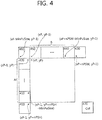
- FIG. 4 is a diagram schematically illustrating an example of a method of performing AMVP by using a specific block.
- the location of a pixel placed at the left top of a current prediction unit may be defined as (xP, yP) and the width and height of the current prediction unit may be defined as parameters nPSW and nPSH, respectively.
- the size of the smallest prediction unit which may be used as a prediction unit may be defined as MinPuSize.
- a block including a pixel at a location may be called a left first block 400 corresponding to a block E 350 of FIG. 3 , for convenience of description.
- any one of blocks from a block belonging to the set A for example, a block 420 including a pixel at a location (xP-1, yP) to a block 410 including a pixel at a location (xP-1, yP+nPSH-MinPuSize) may be called a left second block.
- a block including a pixel at a location (xP+nPSW, yP-1) may be called a top first block 430 corresponding to a block C 330 of FIG. 3 .
- any one of blocks from a block belonging to the set B for example, a block 450 at a location (xP, yP-1) to a block 440 including a pixel at a location (xP+nPSW-MinPuSize, yP-1) may be called as a top second block.
- a block including a pixel at a location (xP-MinPuSize, yP-1) may be called a top third block 460 corresponding to a block D 340 of FIG. 3 .
- the spatial candidate prediction blocks may include the left first block, the left second block, the top first block, the top second block, and the top third block.
- the block 410 including the pixel at the location (xP-1, yP+nPSH-MinPuSize) is used as the left second block
- the block 440 including the pixel at the location (xP+nPSW-MinPuSize, yP-1) is used as the top second block.
- One group including the left first block 400 and the left second block 410 is defined as a first spatial candidate prediction group, and one group including the top first block 430, the top second block 440, and the top third block 460 is defined as the second spatial candidate prediction group.
- a term called a spatial candidate prediction block may be used as a term that includes the blocks included in the first spatial candidate prediction group and the blocks included in the second spatial candidate prediction group.
- a temporal candidate prediction block 470 may become a prediction block including the pixel at the location (xP+nPSW, yP+nPSH) in the collocated picture of the current prediction block on the basis of the location (xP, yP) of a picture included in the current prediction block or a prediction block including a pixel at a location (xP+nPSW/2, yP+nPSH/2) if the prediction block including the pixel at the location (xP+nPSW, yP+nPSH) is not available.
- the locations of the spatial candidate prediction blocks shown in FIG. 4 and the number thereof and the location of the temporal candidate prediction block shown in FIG. 4 and the number thereof are random.
- the location and number of spatial candidate prediction blocks and the location and number of temporal candidate prediction blocks may be changed without departing from the gist of the present invention. For example, all or some of the blocks of the set A and the set B of FIG. 3 may be taken into consideration.
- the location of a prediction block and a candidate prediction group that are first scanned may be changed.
- each of the prediction blocks may be a prediction unit PU.
- FIG. 5 is a flowchart illustrating an example of a method of the decoder deriving a prediction motion vector for a current block.
- the method described with reference to FIG. 5 may be performed by the decoder or a specific module, for example, the prediction module of the decoder. It is assumed that the subject for performing the method of FIG. 5 is the decoder, for convenience of description.
- the decoder may derive a first candidate prediction motion vector at step S500.
- the first candidate prediction motion vector is a candidate prediction motion vector derived from the first spatial candidate prediction group and may be derived on the basis of information on the availability of the first spatial candidate prediction group.
- the first spatial candidate prediction group may include a left first block and a left second block as described in connection with the example of FIG. 4 .
- the information on the availability of the first spatial candidate prediction group may be used to derive the prediction motion vector from the first spatial candidate prediction group.
- the information on the availability of the first spatial candidate prediction group indicates whether at least one of the motion vectors of blocks included in the first spatial candidate prediction group is an available candidate prediction motion vector or not. That is, the information on the availability of the first spatial candidate prediction group indicates whether at least one of the motion vectors of the blocks included in the first spatial candidate prediction group may be included in the candidate prediction motion vector list of a current prediction block or not.
- the decoder may derive a second candidate prediction motion vector at step S510.
- the second candidate prediction motion vector is a candidate prediction motion vector derived from the second spatial candidate prediction group and may be derived on the basis of information on the availability of the second spatial candidate prediction group.
- the second spatial candidate prediction group may include a top first block, a top second block, and a top third block as described above.
- the information on the availability of the second spatial candidate prediction group may be used to derive the prediction motion vector from the second spatial candidate prediction group.
- the information on the availability of the second spatial candidate prediction group like the information on the availability of the first spatial candidate prediction group, indicates whether at least one of the motion vectors of blocks included in the second spatial candidate prediction group may be included in the candidate prediction motion vector list of the current prediction block or not.
- the decoder may obtain a temporal candidate prediction motion vector at step S520.
- the temporal candidate prediction motion vector is a candidate prediction motion vector derived from a temporal candidate prediction block on the basis of the information on the availability of the temporal candidate prediction block.
- the information on the availability of the temporal candidate prediction block indicates whether the motion vector of the temporal candidate prediction block will be included in the candidate prediction motion vector list of the current prediction block.
- the candidate prediction motion vector list may include at least one of the motion vectors obtained through the steps S500 to S520, that is, the first candidate prediction motion vector, the second candidate prediction motion vector, and the temporal candidate prediction motion vector.
- the decoder may exclude the same candidate prediction motion vectors from the candidate prediction motion vector list at step S530. More particularly, if the same candidate prediction motion vectors are present in the candidate prediction motion vector list, the decoder removes the remaining candidate prediction motion vectors other than a candidate prediction motion vector having the highest priority, from among the same candidate prediction motion vectors, from the candidate prediction motion vector list.
- the decoder may add a zero motion vector to the candidate prediction motion vector list at step S540. More particularly, if a necessary number of candidate prediction motion vectors are not derived in order to use the candidate prediction motion vector list, the decoder may add the zero motion vector to the candidate prediction motion vector list.
- the step S540 may be integrally performed along with a step S550 to be described later. In this case, the step S540 may not be performed.
- the decoder may adjust the number of candidate prediction motion vectors at step S550. More particularly, the decoder determines whether or not the number of candidate prediction motion vectors included in a current candidate prediction motion vector list is equal to or greater than the maximum number of candidate prediction motion vectors that may be included in the candidate prediction motion vector list.
- the number of candidate prediction motion vectors that may be included in the candidate prediction motion vector list may be limited to a specific number. For example, assuming that the maximum number of candidate prediction motion vectors is set to 2 and the number of candidate prediction motion vectors derived through the steps S500 to S540 is 3, only two candidate prediction motion vectors in order of high priority may be included in the candidate prediction motion vector list and the remaining one candidate prediction motion vector may be excluded from the candidate prediction motion vector list.
- the decoder adjusts the number of candidate prediction motion vectors so that only the number of candidate prediction motion vectors equal to the maximum number of candidate prediction motion vectors is included in the prediction motion vector list.
- a method of including the number of candidate prediction motion vectors equal to the maximum number of candidate prediction motion vectors in the candidate prediction motion vector list in order of high priority and excluding the remaining candidate prediction motion vectors from the candidate prediction motion vector list may be used as an example of a method of adjusting the number of candidate prediction motion vectors.
- the decoder may add a candidate prediction motion vector to the candidate prediction motion vector list.
- the zero motion vector may be added to a current candidate prediction motion vector list as an additional candidate prediction motion vector.
- the added candidate prediction motion vector may become a combination of vectors already present in the candidate prediction motion vector list or a scaled value in addition to the zero motion vector.
- the decoder may determine a prediction motion vector of the current prediction block at step S560.
- the decoder may use the most efficient candidate prediction motion vector, from among the candidate prediction motion vectors included in the candidate prediction motion vector list, as a motion vector predictor (mvp) of the current prediction block, as described above with reference to FIG. 3 .
- mvp motion vector predictor
- the encoder may transfer information on the most efficient candidate prediction motion vector to the decoder.
- the decoder may determine the motion vector predictor of a current prediction unit on the basis of the information on the index of the motion vector predictor received from the encoder.
- the information on the index of the motion vector predictor may indicate that which of the candidate prediction motion vectors included in the candidate prediction motion vector list will be used as the motion vector predictor of a current prediction block.
- Information on the motion vector of the current prediction unit may be obtained by adding information on a motion vector difference (mvd), that is, information on a difference between the motion vector predictor of the current prediction block and the original motion vector value of the current prediction block.
- mvd motion vector difference
- FIG. 6 is a diagram schematically illustrating an example of the motion vector of a spatial candidate prediction block for a current prediction block.
- the motion vector of a spatial candidate prediction block obtained from the same reference index and reference picture list as those of a current prediction block is a first motion vector 600.
- the reference index indicates a reference picture.
- the motion vector of the spatial candidate prediction block 670 and the motion vector of the current prediction block 650 have the same reference picture and the same reference picture list because a picture indicated by the motion vector 600 of a spatial candidate prediction block 670 is a j picture and a reference picture list including the j picture is L0.
- a motion vector having the same reference picture (or the same reference index) as that of the current prediction block and derived from the same list, is called the first motion vector 600.
- a motion vector of the spatial candidate prediction block 670 having the same reference index as that of the current prediction block 650 and derived from a different reference picture list, is called a second motion vector 610.
- the motion vector 610 of the spatial candidate prediction block 670 and the motion vector of the current prediction block 650 have the same reference index (or the same reference picture), but are derived from different reference picture lists because a picture indicated by the motion vector 610 of the spatial candidate prediction block 670 is a j picture and a reference picture list including the j picture is L1 in the example of FIG. 6 .
- a motion vector, having the same reference index as that of a current prediction block, but derived from a different reference picture list, is called the second motion vector 610.
- a motion vector of a spatial candidate prediction block having a different reference index from a current prediction block, but derived from the same reference picture list, is called a third motion vector 620.
- the motion vector of the spatial candidate prediction block 670 and the motion vector of the current prediction block 650 have different reference indices, but are derived from the same reference picture list because a picture indicated by the motion vector 620 of the spatial candidate prediction block 670 is an i picture and a reference picture list including the i picture is L0 in the example of FIG. 6 .
- a motion vector, having a different reference index from that of the current prediction block 650, but derived from the same list is called the third motion vector 620.
- the motion vector of the spatial candidate prediction block 670 may be scaled on the basis of the reference picture of the current prediction block 650 and then included in a candidate prediction motion vector list.
- a motion vector of the spatial candidate prediction block 670 having a different reference index from that of the current prediction block 650 and derived from a different reference picture list, is called a fourth motion vector 630.
- the motion vector of the spatial candidate prediction block 670 and the motion vector of the current prediction block 650 have different reference indices and have different reference picture list because a picture indicated by the motion vector 630 of the spatial candidate prediction block 670 is an m picture and a reference picture list including the m picture is L1 in the example of FIG. 6 .
- a motion vector, having a different reference index from that of a current prediction block and derived from a different reference picture list, is called the fourth motion vector 630.
- the motion vector of the spatial candidate prediction block is scaled on the basis of the reference picture of the current prediction block 650 and then included in a candidate prediction motion vector list.
- the decoder may search a left first block and a left second block for the first motion vector, the second motion vector, the third motion vector, and the fourth motion vector sequentially.
- the decoder may search the left first block for the first motion vector and the second motion vector. If, as a result of the search, the first motion vector and the second motion vector are not retrieved, the decoder may search the left second block for the first motion vector and the second motion vector. In another embodiment, the decoder may search the left first block and the left second block sequentially for the first motion vector. If, as a result of the search, the first motion vector is not retrieved, the decoder may search the left first block and the left second block sequentially for the second motion vector.
- the decoder may search the left first block and the left second block for the third motion vector and the fourth motion vector likewise.
- the decoder may set information on the availability of a first spatial candidate prediction group to 1 (i.e., true), include the retrieved motion vector in a candidate prediction motion vector list, and terminate subsequent searches.
- the decoder may search an above first block, an above second block, and an above third block sequentially for the first motion vector, the second motion vector, the third motion vector, and the fourth motion vector.
- the search method is the same as that for left blocks. If a motion vector is retrieved, the decoder may set information on the availability of a second spatial candidate prediction group to 1 (i.e., true), include the retrieved motion vector in a candidate prediction motion vector list, and terminate subsequent searches.
- the third motion vector and the fourth motion vector need to be scaled in order to include the third and the fourth motion vectors in the candidate prediction motion vector list and use them.
- the number of times of scaling may be limited. For example, if the predetermined number of times has been fully used to search the left first block and the second block for the third motion vector and the fourth motion vector, a search for the third motion vector and the fourth motion vector in the above blocks may not be performed.
- the decoder may include a candidate prediction motion vector, derived from a temporal candidate prediction block (i.e., a Col block), in the candidate prediction motion list.
- a temporal candidate prediction block i.e., a Col block
- the decoder may remove the remaining candidate prediction motion vectors other than a candidate prediction motion vector having the highest priority, from among the same candidate prediction motion vectors, from the candidate prediction motion list. Furthermore, the decoder may adjust the number of candidate prediction motion vectors by using a zero motion vector, etc.
- L0 and L1 refer to reference picture lists used in inter-prediction depending on the type of picture.
- Pictures used in video coding and decoding may be classified into an I picture, a P picture, and a B picture.
- the I picture is independently coded within a corresponding frame irrespective of frames anterior and posterior to the corresponding frame and is not subject to prediction in the time direction. Only information within the corresponding frame is used in coding processing.
- the P picture may be coded by inter-prediction in one direction using one reference picture.
- the P picture requires one reference picture list, and the one reference picture list is called a reference picture list 0 L0.
- Inter-prediction using a reference picture selected from L0 is also called L0 prediction.
- the L0 prediction is chiefly used in forward prediction. In the P picture, the intra-prediction or the L0 prediction may be performed.
- the B picture may be coded by forward, backward, or bi-direction inter-prediction by using one or more reference pictures, for example, two reference pictures.
- the B picture requires two reference pictures lists, and the two reference pictures list are called a reference picture list 0 L0 and a reference picture list 1 L1, respectively.
- inter-prediction using a reference picture selected from L0 is called L0 prediction, and the L0 prediction is chiefly used in forward prediction.
- Inter-prediction using a reference picture selected from L1 is called L1 prediction, and the L1 prediction is chiefly used in backward prediction.
- inter-prediction using two reference pictures selected from the respective L0 and L1 is also called bi-prediction.
- the intra-prediction, the L0 prediction, the L1 prediction, or the bi-prediction may be performed.
- GPB generalized P and B
- coding having high coding performance, but having low delay is possible.
- FIG. 7 is a diagram schematically illustrating a method of predicting a P picture, a B picture, and GPB.
- the pictures are shown in order of picture order count (POC).
- the POC means the display order or time order of pictures.
- unidirectional prediction from one reference picture is possible. Accordingly, in time order (in POC), forward prediction from the past picture may be performed and backward prediction from the future picture may be performed as shown in FIG. 7 .
- POC time order
- forward prediction from the past picture may be performed and backward prediction from the future picture may be performed as shown in FIG. 7 .
- only one piece of motion information i.e., a motion vector or a reference index
- a motion vector or a reference index about a target prediction block in one direction
- a maximum of two pieces of motion information may be used. Accordingly, forward prediction may be performed using the past two reference pictures on the basis of a B picture, backward prediction may be performed using the future two reference pictures on the basis of a B picture, and bi-prediction may be performed using the past one reference picture and the future one reference picture on the basis of a B picture.
- a B picture capable of performing bi-prediction may need two reference picture lists L0 and L1.
- prediction may be performed on a target prediction block by using two or more pieces of motion information.
- GPB global prediction block
- only forward prediction may be allowed. In this case, delay due to backward prediction is not accompanied.
- the characteristics of the I picture, the P picture, and the B picture may be defined for every slice not for every picture.
- an I slice having the characteristics of the I picture, a P slice having the characteristics of the P picture, and a B slice having the characteristics of the B picture may be defined.
- the GPB may be said to be a GPB slice or a generalized B slice.
- the current block is decoded using a derived motion vector predictor (mvp).
- mvp derived motion vector predictor
- the reference index of a current block may be assigned as a specific value, for example, 0. In this case, however, if a temporal motion vector predictor (TMVP) is used, it is difficult to obtain effective prediction results.
- TMVP temporal motion vector predictor
- FIG. 8 is a diagram schematically illustrating a problem that may occur when a reference index is set to a specific value and skip mode is applied.
- FIG. 8 shows an example in which a reference index is set to a specific value and skip mode is applied.
- the reference index indicates a reference picture 0.
- the reference picture 0 indicated by the reference index is brighter than a reference picture 1 indicated by a reference index 1 and a current picture.
- the reason why the reference picture 0 is brighter may result from a lighting effect, such as a flash when photographing is performed.
- the reference picture 1 rather than the reference picture 0 may be preferably used to predict the current picture.
- blocks neighboring the current block have a good possibility that they may have a reference index indicative of the reference picture 1. If most of the neighbor blocks have the reference picture 1 and skip mode is applied to the current block by using the reference picture 0, a motion vector predictor (mvp) for the current block may have to be determined using the block of a zero motion vector or a collocated picture because there is no candidate block having the same reference index from the more similar motin vector.
- mvp motion vector predictor
- a deriving method using the reference indices of blocks neighboring a current block without designating a specific value as a reference index may be used.
- the problem may be solved using a method of allocating reference indices, distributed over a lot close to the current block, as reference indices for skip mode.
- a reference index to be allocated to skip mode may be determined by tracking a motion informatin of the neighbor blocks of the current block.
- a specific reference index is not assigned 0, but reference indices distributed over a lot close to the current block are designated as the reference indices of the current block. That is, the reference index of a specific block, from among blocks neighboring the current block, is used as the reference index of the current block, and detailed methods thereof are described in connection with the following embodiments.
- the reference index that is used the most, from among the reference indeices of blocks neighboring a current block, is used as the reference index of the current block.
- a reference index that is the largest in number, from among the reference indices of blocks belonging to the set A 310, the reference indices of blocks belonging to the set B 320, the reference index of the block C 330, and the reference index of the block E 350, may be used as the reference index of the current block 300.
- the reference index of the block D 340 may be used instead.
- a reference index having a smaller value may be designated as the reference index of a current block.
- the reference index having a smaller value may be a reference index having higher priority.
- the reference index having a smaller value may be a reference index indicative of a reference picture having a lower index in a reference picture list.
- a median for the reference indices of left blocks neighboring a current block and a median for the reference indices of top blocks neighboring the current block are derived.
- a median for the two medians and the reference index of a block located at the corner of the current block are designated as the reference index of the current block.
- a Median (refidxAl, ..., refidxAN) for the reference indices refidxA1, ..., refidxAN of N blocks belonging to the set A 310 are called refA.
- a Median (refidxB1, ..., refidxBM) for the reference indices refBl, ..., refidxBN of M blocks belonging to the set B 320 is called refB.
- the reference index of the block C 330 is refC
- a Medians (refA, refB, and refC) may be designated as the reference index of the current block 300.
- the reference index of the block D 340 or the reference index of the block E 350 may be used instead of the reference index of the block C 330.
- a reference index having the smallest value, from among the reference indices of neighbor blocks located at the top of a current block, and a reference index having the smallest value, from among the reference indices of neighbor blocks on the left of the current block, are derived.
- a reference index having a smaller value, from among the two reference indices, is designated as the reference index of the current block.
- the reference indices of the three blocks located at the corners of the current block 300 may be further included as the reference index of the current block 300.
- a reference index having the smallest value, from among the reference indices refA, refB, refC, refD, and refE, may be designated as the reference index of the current block 300.
- the encoder may send a reference index (or a reference picture index) to be used in a current block to which skip mode is applied through a parameter set of a slice level or a picture level.
- the current block may be a coding unit or a prediction unit.
- Information on the reference index that is transmitted by the encoder in a slice level or a picture level may be a value itself of the reference index.
- reference indices transmitted by the encoder may be the reference indices of blocks that neighbor the current block. Accordingly, the encoder may not directly send the value of a reference index, but send information on the reference index in such a way as to send information indicative of a neighbor block having the corresponding reference index. In this case, if the motion vector of a block designated by the encoder is the same as that of the current block, motion information on the block designated by the encoder may be used without change and skip mode may be applied to the current block.
- This method may also be called a method of merging neighbor blocks with a current block and applying skip mode to the current block, for convenience of description.
- the decoder designates the reference indices, received from the encoder, as the reference indices of blocks to which skip mode is applied. Since the reference indices for skip mode are transmitted in a slice level or a picture level, the same reference index may be assigned to the blocks to which skip mode is applied, that is, blocks belonging to the same slice or the same picture.
- the decoder derives a motion vector predictor (mvp) for a current block by using reference indices received from the encoder and an AMVP method, such as that described above.
- the decoder may apply skip mode to the current block in such a way as to use motion information on the indicated neighbor block without change. That is, a method of merging the neighbor block with the current block and applying skip mode to the current block may be used.
- the encoder sends a reference index to be used by a current block to which skip mode is applied for every block.
- a block through which the reference index is transmitted may be a coding unit or a prediction unit.
- Information on the reference index transmitted by the encoder for every block may be a value itself of the reference index.
- reference indices received from the encoder may be the reference indices of blocks that neighbor the current block. Accordingly, the encoder may not directly send the value of a reference index, but send information on the reference index in such a way as to send information indicative of a neighbor block having the corresponding reference index. In this case, if the motion vector of a block designated by the encoder is the same as that of the current block, motion information on the block designated by the encoder may be used without change and skip mode may be applied to the current block.
- This method may also be called a method of merging neighbor blocks with a current block and applying skip mode to the current block, for convenience of description.
- the decoder uses a reference index, transmitted by the encoder, as the reference index of the current block.
- a reference index transmitted by the encoder
- the decoder may apply skip mode to the current block in such a way as to use motion information on the indicated neighbor block without change. That is, a method of merging the neighbor block with the current block and applying skip mode to the current block may be used.
- a reference index having the smallest value, from among the reference indices of neighbor blocks, is selected and used.
- FIG. 9 is a diagram schematically illustrating a method of selecting the reference index of a current block from the reference indices of neighbor blocks in accordance with an embodiment of the present invention.
- the reference index of the current block 910 may be determined by taking the reference index of a block A 930 and the reference index of a block B 950 into consideration.
- the block A 930 may be any one of the blocks of a set A 920
- the block B 950 may be any one of the blocks of a set B 940.
- Each of the reference index of the block A 930 and the reference index of the block B 950 may have a value of -1 (i.e., unavailable) for a reference picture list L1 in the case of forward prediction and may have a value of -1 for a reference picture list L0 in the case of backward prediction. Furthermore, if the block A 930 or the block B 950 is in intra-mode, all the values of reference picture indices may become -1 in relation to bi-direction prediction.
- Table 1 shows reference picture indices that are designated according to the embodiment 6 regarding the designation of a reference index in skip mode.
- a reference index for skip mode is obtained for each of an L0 direction and an L1 direction, and prediction is performed using a derived reference index.
- a reference index skip_ref in skip mode may be derived as in Equation 2 by using the reference index ref_idx_A of the block A 930 and the reference index ref_idx_B of the block B 950.
- the reference index of a current block in skip mode may be derived as 0 or -1.
- skip mode may be predicted in one direction. For example, if a value of a skip mode reference index skip_rel_10 in an L0 direction is -1 and a value of a skip mode reference index in an L1 direction is 0, skip mode in the L1 direction is applied to a current block.
- intra-prediction mode for a current block is merge mode
- a predictin may be performed in such a way as to apply motion information (i.e., a reference index and a motion vector) on a predetermined merge candidate to the current blockmay be predicted in such a way as to apply merge mode to the current block.
- motion information i.e., a reference index and a motion vector
- skip of merge mode may be applied to the current block as described above. This may be simply called merge skip mode.
- merge mode In merge mode or merge skip mode, motion information on a designated candidate block is used as motion information on a current block. In merge skip mode, unlike in merge mode, a residual signal for a prediction block is not transmitted. Information indicating whether merge mode or merge skip mode is applied to a current block may be transmitted by the encoder.
- an indicator transmitted by the encoder may indicate a target with which the current block will be merged in a merge candidate list mergeCandList.
- FIG. 10 is a diagram schematically illustrating merge candidates in a system to which the present invention is applied.
- candidates that may be used as motion information on the current block includes pieces of motion information on a block A 0 1010, that is, the left-bottom corner block of the current block, a block A 1 1020, that is, the left-bottom block of the current block, a block B 0 1030, that is, the right-top corner block of the current block, a block B 1 1040, that is, the right-top block of the current block, a block B 2 1050, that is, the left-top corner block of the current block, and a block COL 1050, that is, a block at the same location as the current block.
- a 1 , B 0 , B 1 , B 2 , or COL may indicate a block or motion information.
- a merge candidate list may be indexed in order of A 1 , B 1 , B 0 , A 0 , B 2 , and COL when a value of an availability flag for each candidate is 1 (true).
- a candidate including an availability flag having a value not 1 maynot be included in the merge candidate list.
- the remaining candidates other than a candidate having lower order (or higher priority or lower index), from among the candidates having the same motion information and the same index may be removed from the merge candidate list.
- the maximum number of candidates that may be included in a merge candidate list may be fixed to a specific number. For example, only a maximum number of 5 candidates may be included in a merge candidate list.
- a current block to which merge mode or merge skip mode is applied is merged with a candidate block indicated by an index transmitted by the encoder in a merge candidate list, and the current block uses motion information on the candidate block as its motion information.
- the motion information of the candidate block used as the motion information of the current block can include a prediction flag indicative of the availability of L1/L2 in addition to a motion vector and a reference index.
- a method of deriving A 0 , A 1 , B 0 , B 1 , or B 2 as a merge candidate is performed by determining the availability of each candidate.
- the block A 0 , the block A 1 , the block B 0 , the block B 1 , and the block B 2 cover (xP-1, yP+nPSH), (xP-1, yP+nPSH-1), (xP+nPSW, yP-1), (xP+nPSW-1, yP-1), and (xP-1, yP-1), respectively.
- the location of each block may be indicated by (xN, yN), for convenience of description.
- a value of an availability flag is set to 0, and the elements values of a corresponding motion vector are also set to 0.
- a value of an availability flag for a corresponding candidate is set to 1, and the motion vector, the reference index, and the prediction flag of a block (e.g., a prediction unit) that covers a location (xN, yN) are designated as respective mvLXN, refldxLXN, and predFlagLXN of a merge candidate list.
- a temporal merge candidate (i.e., a Col block) may be derived differently from the aforementioned spatial merge candidates.
- the motion vector of the temporal merge candidate may be selected at a specific location in relation to a block corresponding to a current block in a Col picture.
- the motion vector of a block located at the right-bottom corner of a block corresponding to a current block may be selected as the motion vector of a temporal merge candidate.
- the reference index of a temporal merge candidate may be derived on the basis of the reference indices of blocks neighboring a current block without using a Col picture.
- a reference index refldxLXA (X is 0 or 1) may be derived from the block A 1 1020 as follows.
- refldxLX [xP-1, yP+nPSH-1] is assigned to the reference index refldxLXA.
- the sample at the location (xP-1, yP+nPSH-1) may be a luma sample, and the block A 1 1020 that covers the location (xP-1, yP+nPSH-1) of the sample and the current block 1000 may be prediction units.
- a reference index refldxLXB (X is 0 or 1) may be derived from the block B 1 1040 as follows.
- refldxLX [xP+nPSW-1, yP-1] is assigned to the reference index refIdxLXB.
- the sample at the location (xP+nPSW-1, yP-1) may be a luma sample, and the block B 1 1040 that covers the location (xP+nPSW-1, yP-1) of the sample and the current block 1000 may be prediction units.
- a reference index refldxLXC (X is 0 or 1) may be derived from the three corner blocks A 0 1010, B 0 1030, and B 2 1050 as follows.
- refIdxLX [xP+nPSW, yP-1] is assigned to the reference index refIdxLXC.
- the sample at the location (xP+nPSW, yP-1) may be luma sample, and the block B 0 1030 that covers the location (xP+nPSW, yP-1) of the sample and the current block 1000 may be prediction units.
- the block B 0 1030 is not available or prediction mode is intra-prediction mode
- the block A 0 1010 that covers the location (xP-1, yP+nPSH) of a sample is available, and prediction mode is not intra-prediction mode MODE INTRA, refldxLX [xP-1, yP+nPSH] is assigned to the reference index refIdxLXC.
- the sample at the location (xP-1, yP+nPSH) may be a luma sample
- the block A 0 1010 that covers the location (xP-1, yP+nPSH) of the sample and the current block 1000 may be prediction units.
- the block B 2 1050 that covers the location (xP-1, yP-1) of a sample is available, and prediction mode is not intra-prediction mode MODE_INTRA, refIdxLX[xP-1, yP-1] is assigned to the reference index refIdxLXC.
- the sample at the location (xP-1, yP-1) may be a luma sample, and the block B 2 1050 that covers the location (xP-1, yP-1) of the sample and the current block 1000 may be prediction units.
- a value of -1 is assigned to the reference index refldxLXC.
- the reference index refIdxLX of a temporal merge candidate for the current block 1000 may be derived as in the following cases.
- the reference index refldxLX of the temporal merge candidate may be said to be a reference index having the smallest value, from among the reference index refldxLXA selected from the left of the current block 1000, the reference index refIdxLXB selected from the upper side of the current block, and the reference index refIdxLXC selected as the first available reference index from the corners of the current block 1000.
- the present embodiment proposes a method of simply deriving the reference index of a temporal merge candidate for a current block when merge mode or merge skip mode is applied to the current block.
- a fixed value may be used as the reference index of a temporal merge candidate for a current block.
- the reference index refldxLX of the temporal merge candidate may be designated as 0.
- the reference index refIdxL0 of a reference picture list L0 is fixed to 0 and the reference index refldxLl of a reference picture list L1 is fixed to 1.
- the reference index of a temporal merge candidate for a current block may be determined as in Equation 3 below.
- refIdxL 0 0
- a reference index having a smaller value from among the reference index of the block A 1 1020 and the reference index of the block B 1 1040, may be determined as the reference index of a temporal merge candidate for the current block 1000.
- the reference index refldxLX of the temporal merge candidate may be derived as in the following cases.
- a value 0 is assigned to the reference index refldxLX of a temporal merge candidate for a current block.
- the reference index refldxLX of the temporal merge candidate for the current block is set to 0.
- the reference index refldxLXA is the reference index of the block A 1 1020
- the reference index refIdxLXB is the reference index of the block B 1 1040.
- the reference index refldxLXA derived from the left of a current block is used as the reference index refldxLX of a temporal merge candidate for the current block.
- the reference index refldxLXA is the reference index of the block A 1 1020.
- the reference index refldxLXB derived from the upper side of the current block 1000 is used as the reference index of the temporal merge candidate.
- the reference index refIdxLXB is the reference index of the block B1 1040.
- the reference index refIdxLX of the temporal merge candidate is set to 0. That is,
- FIG. 11 is a diagram schematically illustrating an example of the operation of the encoder in a system to which the present invention is applied.
- the encoder performs prediction on a current block at step S1110.
- the encoder performs partition on a coding unit.
- the encoder determines prediction mode for the current block, that is, a prediction target, and performs the prediction in the determined prediction mode.
- Prediction mode for the current block may be intra-prediction mode or inter-prediction mode. If prediction mode for the current block is inter-prediction, merge mode, (merge) skip mode, or AMVP may be applied to the current block.
- a motion vector and a reference index of the current block may be determined using neighbor blocks.
- a reference index of the current block may be determined by taking motion information on the neighbor blocks of the current block into consideration.
- a motion vector and a reference index of the current block may be determined on the basis of motion information on the neighbor blocks of the current block.
- the encoder performs the prediction on the current block on the basis of the determined motion information.
- the encoder performs entropy coding on information on which the prediction has been performed at step S1120.
- the encoder also performs entropy coding on information necessary for decoding along with the information on the prediction.
- the entropy-coded information includes motion information on the current block in skip mode, merge mode, etc. as described above.
- the encoder signals the entropy-coded information to the decoder at step S1130.
- FIG. 12 is a flowchart schematically illustrating an example of the operation of the decoder in a system to which the present invention is applied.
- the decoder receives coded information at step S1210.
- the information may have been subjected to entropy coding by the encoder and transferred through a bit stream.
- the decoder performs entropy decoding on the received information at step S1220.
- the decoder performs prediction on a current block on the basis of the entropy-decoded information at step S1230.
- the decoder performs prediction in prediction mode for the current block.
- prediction mode for the current block is inter-prediction mode and skip mode is applied to the current block
- motion information e.g., a motion vector and a reference index
- the decoder reconstructs a video on the basis of the results of the prediction at step S 1240.
Landscapes
- Engineering & Computer Science (AREA)
- Multimedia (AREA)
- Signal Processing (AREA)
- Physics & Mathematics (AREA)
- Discrete Mathematics (AREA)
- General Physics & Mathematics (AREA)
- Compression Or Coding Systems Of Tv Signals (AREA)
Priority Applications (2)
| Application Number | Priority Date | Filing Date | Title |
|---|---|---|---|
| HRP20221363TT HRP20221363T1 (hr) | 2011-01-07 | 2012-01-06 | Postupak kodiranja video informacija, postupak dekodiranja video informacija i uređaj za dekodiranje za dekodiranje video informacija |
| SI201232011T SI3554079T1 (sl) | 2011-01-07 | 2012-01-06 | Postopek za kodiranje video informacij, postopek za dekodiranje video informacij in dekodirna naprava za dekodiranje video informacij |
Applications Claiming Priority (5)
| Application Number | Priority Date | Filing Date | Title |
|---|---|---|---|
| US201161430545P | 2011-01-07 | 2011-01-07 | |
| US201161449699P | 2011-03-06 | 2011-03-06 | |
| US201161543296P | 2011-10-04 | 2011-10-04 | |
| EP12732289.9A EP2663079A4 (fr) | 2011-01-07 | 2012-01-06 | Procédé de codage et de décodage d'informations d'image et dispositif l'utilisant |
| PCT/KR2012/000170 WO2012093898A2 (fr) | 2011-01-07 | 2012-01-06 | Procédé de codage et de décodage d'informations d'image et dispositif l'utilisant |
Related Parent Applications (1)
| Application Number | Title | Priority Date | Filing Date |
|---|---|---|---|
| EP12732289.9A Division EP2663079A4 (fr) | 2011-01-07 | 2012-01-06 | Procédé de codage et de décodage d'informations d'image et dispositif l'utilisant |
Publications (2)
| Publication Number | Publication Date |
|---|---|
| EP3554079A1 true EP3554079A1 (fr) | 2019-10-16 |
| EP3554079B1 EP3554079B1 (fr) | 2022-10-19 |
Family
ID=46457881
Family Applications (5)
| Application Number | Title | Priority Date | Filing Date |
|---|---|---|---|
| EP22200464.0A Active EP4135329B1 (fr) | 2011-01-07 | 2012-01-06 | Procédé de codage et de décodage d'informations d'image et dispositif l'utilisant |
| EP19176192.3A Active EP3554079B1 (fr) | 2011-01-07 | 2012-01-06 | Procédé de codage vidéo, procédé de décodage vidéo et dispositif de décodage vidéo |
| EP25168743.0A Pending EP4557738A3 (fr) | 2011-01-07 | 2012-01-06 | Procédé de codage et de décodage d'informations d'image et dispositif l'utilisant |
| EP25168737.2A Pending EP4557737A3 (fr) | 2011-01-07 | 2012-01-06 | Procédé de codage et de décodage d'informations d'image et dispositif l'utilisant |
| EP12732289.9A Ceased EP2663079A4 (fr) | 2011-01-07 | 2012-01-06 | Procédé de codage et de décodage d'informations d'image et dispositif l'utilisant |
Family Applications Before (1)
| Application Number | Title | Priority Date | Filing Date |
|---|---|---|---|
| EP22200464.0A Active EP4135329B1 (fr) | 2011-01-07 | 2012-01-06 | Procédé de codage et de décodage d'informations d'image et dispositif l'utilisant |
Family Applications After (3)
| Application Number | Title | Priority Date | Filing Date |
|---|---|---|---|
| EP25168743.0A Pending EP4557738A3 (fr) | 2011-01-07 | 2012-01-06 | Procédé de codage et de décodage d'informations d'image et dispositif l'utilisant |
| EP25168737.2A Pending EP4557737A3 (fr) | 2011-01-07 | 2012-01-06 | Procédé de codage et de décodage d'informations d'image et dispositif l'utilisant |
| EP12732289.9A Ceased EP2663079A4 (fr) | 2011-01-07 | 2012-01-06 | Procédé de codage et de décodage d'informations d'image et dispositif l'utilisant |
Country Status (11)
| Country | Link |
|---|---|
| US (8) | US9924188B2 (fr) |
| EP (5) | EP4135329B1 (fr) |
| KR (8) | KR101929026B1 (fr) |
| CN (4) | CN103299642B (fr) |
| ES (2) | ES3027360T3 (fr) |
| HR (2) | HRP20221363T1 (fr) |
| HU (2) | HUE071305T2 (fr) |
| PL (2) | PL3554079T3 (fr) |
| RS (1) | RS66726B1 (fr) |
| SI (1) | SI3554079T1 (fr) |
| WO (1) | WO2012093898A2 (fr) |
Families Citing this family (72)
| Publication number | Priority date | Publication date | Assignee | Title |
|---|---|---|---|---|
| US9398308B2 (en) | 2010-07-28 | 2016-07-19 | Qualcomm Incorporated | Coding motion prediction direction in video coding |
| US9066102B2 (en) * | 2010-11-17 | 2015-06-23 | Qualcomm Incorporated | Reference picture list construction for generalized P/B frames in video coding |
| CN107197257B (zh) | 2010-12-08 | 2020-09-08 | Lg 电子株式会社 | 由编码装置和解码装置执行的内预测方法 |
| US9648334B2 (en) * | 2011-03-21 | 2017-05-09 | Qualcomm Incorporated | Bi-predictive merge mode based on uni-predictive neighbors in video coding |
| CA2830036C (fr) | 2011-04-12 | 2019-03-05 | Panasonic Corporation | Procede de codage de video animee, appareil de codage de video animee, procede de decodage de video animee, appareil de decodage de video animee et appareil de codage/decodage de video animee |
| ES2911670T3 (es) | 2011-05-27 | 2022-05-20 | Sun Patent Trust | Aparato, procedimiento y programa para decodificar imágenes en movimiento |
| US9485518B2 (en) | 2011-05-27 | 2016-11-01 | Sun Patent Trust | Decoding method and apparatus with candidate motion vectors |
| WO2012164908A1 (fr) | 2011-05-31 | 2012-12-06 | パナソニック株式会社 | Procédé de codage de vidéo, dispositif de codage de vidéo, procédé de décodage de vidéo, dispositif de décodage de vidéo, et dispositif de codage/décodage de vidéo |
| WO2013001749A1 (fr) * | 2011-06-29 | 2013-01-03 | パナソニック株式会社 | Procédé de codage d'image, procédé de décodage d'image, dispositif de codage d'image, dispositif de décodage d'image et dispositif de codage/décodage d'image |
| BR112013029425B1 (pt) | 2011-06-30 | 2022-03-29 | Sun Patent Trust | Método de decodificação de imagem, método de codificação de imagem, dispositivo de decodificação de imagem, dispositivo de codificação de imagem, e dispositivo de codifica ção/decodificação de imagem |
| CN103718558B (zh) | 2011-08-03 | 2017-04-19 | 太阳专利托管公司 | 运动图像编码方法及装置、解码方法及装置和编解码装置 |
| KR20130030181A (ko) * | 2011-09-16 | 2013-03-26 | 한국전자통신연구원 | 움직임 벡터 예측기를 이용한 움직임 벡터 부호화/복호화 방법 및 장치 |
| US9571834B2 (en) | 2011-09-22 | 2017-02-14 | Lg Electronics Inc. | Method and apparatus for signaling image information, and decoding method and apparatus using same |
| MY180182A (en) | 2011-10-19 | 2020-11-24 | Sun Patent Trust | Picture coding method,picture coding apparatus,picture decoding method,and picture decoding apparatus |
| US20130343459A1 (en) * | 2012-06-22 | 2013-12-26 | Nokia Corporation | Method and apparatus for video coding |
| US9325990B2 (en) * | 2012-07-09 | 2016-04-26 | Qualcomm Incorporated | Temporal motion vector prediction in video coding extensions |
| JPWO2014050948A1 (ja) * | 2012-09-28 | 2016-08-22 | シャープ株式会社 | 画像復号装置、画像復号方法及び画像符号化装置 |
| US10904551B2 (en) * | 2013-04-05 | 2021-01-26 | Texas Instruments Incorporated | Video coding using intra block copy |
| US11109036B2 (en) | 2013-10-14 | 2021-08-31 | Microsoft Technology Licensing, Llc | Encoder-side options for intra block copy prediction mode for video and image coding |
| CN105765974B (zh) | 2013-10-14 | 2019-07-02 | 微软技术许可有限责任公司 | 用于视频和图像编码和解码的帧内块复制预测模式的特征 |
| US9432685B2 (en) * | 2013-12-06 | 2016-08-30 | Qualcomm Incorporated | Scalable implementation for parallel motion estimation regions |
| RU2669005C2 (ru) * | 2014-01-03 | 2018-10-05 | МАЙКРОСОФТ ТЕКНОЛОДЖИ ЛАЙСЕНСИНГ, ЭлЭлСи | Предсказание вектора блока в кодировании/декодировании видео и изображений |
| US10390034B2 (en) | 2014-01-03 | 2019-08-20 | Microsoft Technology Licensing, Llc | Innovations in block vector prediction and estimation of reconstructed sample values within an overlap area |
| US11284103B2 (en) | 2014-01-17 | 2022-03-22 | Microsoft Technology Licensing, Llc | Intra block copy prediction with asymmetric partitions and encoder-side search patterns, search ranges and approaches to partitioning |
| EP4354856A3 (fr) | 2014-06-19 | 2024-06-19 | Microsoft Technology Licensing, LLC | Modes de copie intra-bloc et de prédiction inter unifiés |
| JP2017535145A (ja) | 2014-09-30 | 2017-11-24 | マイクロソフト テクノロジー ライセンシング,エルエルシー | 波面並列処理が可能にされた場合のピクチャ内予測モードに関する規則 |
| US9992512B2 (en) * | 2014-10-06 | 2018-06-05 | Mediatek Inc. | Method and apparatus for motion vector predictor derivation |
| CN114866770B (zh) | 2015-08-07 | 2025-05-16 | Lg电子株式会社 | 视频编译系统中的帧间预测方法和装置 |
| WO2017048008A1 (fr) * | 2015-09-17 | 2017-03-23 | 엘지전자 주식회사 | Procédé et appareil de prédiction inter dans un système de codage vidéo |
| CN116489346A (zh) * | 2015-11-20 | 2023-07-25 | 韩国电子通信研究院 | 对图像进行编/解码的方法和装置 |
| US20200169726A1 (en) * | 2016-04-08 | 2020-05-28 | Electronics And Telecommunications Research Institute | Method and device for inducing motion prediction information |
| CN117041544A (zh) | 2016-04-29 | 2023-11-10 | 世宗大学校产学协力团 | 用于对图像信号进行编码/解码的方法和设备 |
| CN109417629B (zh) | 2016-07-12 | 2023-07-14 | 韩国电子通信研究院 | 图像编码/解码方法以及用于该方法的记录介质 |
| CN109691098A (zh) * | 2016-09-30 | 2019-04-26 | 华为技术有限公司 | 视频编码方法、解码方法及终端 |
| CN116489393A (zh) | 2016-10-14 | 2023-07-25 | 世宗大学校产学协力团 | 影像解码/编码方法、传送比特流的方法及记录介质 |
| CN117528110A (zh) * | 2016-11-28 | 2024-02-06 | 英迪股份有限公司 | 图像编码方法、图像解码方法及用于传送比特流的方法 |
| CN116866593A (zh) * | 2016-11-28 | 2023-10-10 | 韩国电子通信研究院 | 对图像编码/解码的方法和设备及存储比特流的记录介质 |
| DK3541073T3 (da) * | 2016-12-05 | 2021-09-20 | Lg Electronics Inc | Fremgangsmåde og lagringsmedie til dekodning af et billede i et billedkodningssystem |
| US11172203B2 (en) * | 2017-08-08 | 2021-11-09 | Mediatek Inc. | Intra merge prediction |
| KR20250048592A (ko) | 2017-09-26 | 2025-04-09 | 파나소닉 인텔렉츄얼 프로퍼티 코포레이션 오브 아메리카 | 부호화 장치, 복호 장치, 부호화 방법 및 복호 방법 |
| CN118055225A (zh) * | 2017-09-29 | 2024-05-17 | Lx 半导体科技有限公司 | 图像编码/解码方法、存储介质以及图像数据的传输方法 |
| WO2019061537A1 (fr) * | 2017-09-30 | 2019-04-04 | Huawei Technologies Co., Ltd. | Procédé et appareil de dérivation de candidats de données de mouvement temporel dans un codage vidéo |
| CN109922340B (zh) * | 2017-12-13 | 2021-10-15 | 华为技术有限公司 | 图像编解码方法、装置、系统及存储介质 |
| US10986349B2 (en) | 2017-12-29 | 2021-04-20 | Microsoft Technology Licensing, Llc | Constraints on locations of reference blocks for intra block copy prediction |
| CN116366845A (zh) * | 2018-03-09 | 2023-06-30 | 韩国电子通信研究院 | 使用样点滤波的图像编码/解码方法和设备 |
| CN118972615A (zh) | 2018-03-14 | 2024-11-15 | Lx 半导体科技有限公司 | 图像编码/解码方法和发送方法 |
| CN117640961A (zh) | 2018-03-19 | 2024-03-01 | 英迪股份有限公司 | 图像解码方法、图像编码方法和存储比特流的记录介质 |
| CN110662057B (zh) * | 2018-06-29 | 2022-06-21 | 北京字节跳动网络技术有限公司 | 视频处理方法、装置、设备以及存储比特流的方法 |
| CN118972564A (zh) * | 2018-06-30 | 2024-11-15 | 有限公司B1影像技术研究所 | 图像编码/解码方法和设备 |
| US20200014931A1 (en) * | 2018-07-06 | 2020-01-09 | Mediatek Inc. | Methods and Apparatuses of Generating an Average Candidate for Inter Picture Prediction in Video Coding Systems |
| US11019357B2 (en) * | 2018-08-07 | 2021-05-25 | Qualcomm Incorporated | Motion vector predictor list generation |
| CN110876057B (zh) * | 2018-08-29 | 2023-04-18 | 华为技术有限公司 | 一种帧间预测的方法及装置 |
| CN119071508A (zh) | 2018-09-11 | 2024-12-03 | 有限公司B1影像技术研究所 | 图像编码/解码方法和图像传输方法 |
| US10958932B2 (en) | 2018-09-12 | 2021-03-23 | Qualcomm Incorporated | Inter-prediction coding of video data using generated motion vector predictor list including non-adjacent blocks |
| CN116527889A (zh) * | 2018-09-25 | 2023-08-01 | 华为技术有限公司 | 一种图像预测方法和设备 |
| CN119011829A (zh) | 2018-09-25 | 2024-11-22 | 数字洞察力有限公司 | 用于对图像进行编码或解码的方法和装置以及非暂态计算机可读介质 |
| WO2020067679A1 (fr) * | 2018-09-29 | 2020-04-02 | 엘지전자 주식회사 | Procédé et dispositif permettant de former une liste de candidats de fusion |
| CN121462771A (zh) * | 2018-11-08 | 2026-02-03 | Oppo广东移动通信有限公司 | 图像信号编码/解码方法及其设备 |
| CN111200735B (zh) * | 2018-11-19 | 2023-03-17 | 华为技术有限公司 | 一种帧间预测的方法及装置 |
| EP3726839A4 (fr) * | 2018-12-06 | 2021-06-02 | LG Electronics Inc. | Procédé et dispositif de traitement de signaux vidéo sur la base d'une interprédiction |
| KR20200083316A (ko) * | 2018-12-28 | 2020-07-08 | 한국전자통신연구원 | 영상 부호화/복호화 방법, 장치 및 비트스트림을 저장한 기록 매체 |
| WO2020138997A1 (fr) * | 2018-12-28 | 2020-07-02 | 엘지전자 주식회사 | Procédé et dispositif de traitement de signal vidéo à l'aide d'une inter-prédiction |
| WO2020141910A1 (fr) * | 2019-01-02 | 2020-07-09 | 엘지전자 주식회사 | Procédé et dispositif de traitement d'un signal vidéo en utilisant l'inter-prédiction |
| CN111432219B (zh) * | 2019-01-09 | 2023-06-06 | 华为技术有限公司 | 一种帧间预测方法及装置 |
| WO2020143292A1 (fr) * | 2019-01-09 | 2020-07-16 | 华为技术有限公司 | Procédé et appareil de prédiction inter-trames |
| WO2020184953A1 (fr) * | 2019-03-12 | 2020-09-17 | 엘지전자 주식회사 | Codage de vidéo ou d'image permettant d'induire des informations d'indice de pondération pour une bi-prédiction |
| EP3975556A4 (fr) * | 2019-06-19 | 2022-08-03 | Lg Electronics Inc. | Procédé de décodage d'image permettant de réaliser une inter-prédiction lorsque le mode de prédiction du bloc actuel ne peut finalement pas être sélectionné et dispositif associé |
| JP7719728B2 (ja) * | 2019-06-19 | 2025-08-06 | エルジー エレクトロニクス インコーポレイティド | デフォルト(default)マージモードに基づいて予測サンプルを導き出す映像デコーディング方法及びその装置 |
| MX2022000155A (es) * | 2019-07-05 | 2022-02-21 | Lg Electronics Inc | Metodo de codificacion/decodificacion de imagen y dispositivo para derivar el indice de peso de la prediccion bidireccional, y metodo para transmitir un flujo de bits. |
| WO2021172881A1 (fr) | 2020-02-25 | 2021-09-02 | 엘지전자 주식회사 | Procédé et appareil de codage/décodage d'image par prédiction inter, et support d'enregistrement stockant un train de bits |
| US11722658B2 (en) * | 2021-06-25 | 2023-08-08 | Tencent America LLC | Method and apparatus for video coding |
| US20240114163A1 (en) * | 2022-10-04 | 2024-04-04 | Electronics And Telecommunications Research Institute | Encoding apparatus performing inter prediction operation based on an overlap frame and operating method thereof |
Citations (3)
| Publication number | Priority date | Publication date | Assignee | Title |
|---|---|---|---|---|
| US20060294171A1 (en) * | 2005-06-24 | 2006-12-28 | Frank Bossen | Method and apparatus for video encoding and decoding using adaptive interpolation |
| KR20090033847A (ko) * | 2009-03-04 | 2009-04-06 | 엘지전자 주식회사 | 모션 벡터 예측 방법 |
| US20100266042A1 (en) * | 2007-03-02 | 2010-10-21 | Han Suh Koo | Method and an apparatus for decoding/encoding a video signal |
Family Cites Families (28)
| Publication number | Priority date | Publication date | Assignee | Title |
|---|---|---|---|---|
| US7295614B1 (en) * | 2000-09-08 | 2007-11-13 | Cisco Technology, Inc. | Methods and apparatus for encoding a video signal |
| EP2009924A3 (fr) | 2001-11-06 | 2010-07-28 | Panasonic Corporation | Procédé de codage et de décodage d'image mobile |
| KR100931746B1 (ko) | 2002-04-19 | 2009-12-14 | 파나소닉 주식회사 | 움직임 벡터 계산방법 |
| US7433526B2 (en) | 2002-04-30 | 2008-10-07 | Hewlett-Packard Development Company, L.P. | Method for compressing images and image sequences through adaptive partitioning |
| JP2003324742A (ja) * | 2002-05-08 | 2003-11-14 | Hitachi Ltd | 画像符号化装置及び画像復号化装置 |
| KR100865034B1 (ko) | 2002-07-18 | 2008-10-23 | 엘지전자 주식회사 | 모션 벡터 예측 방법 |
| KR20050026318A (ko) | 2003-09-09 | 2005-03-15 | 삼성전자주식회사 | 인트라 스킵 모드를 포함하는 비디오 인코딩_디코딩 장치및 방법 |
| WO2006058921A1 (fr) | 2004-12-03 | 2006-06-08 | Thomson Licensing | Procede de codage video a geometrie variable |
| CN101491095B (zh) * | 2006-03-30 | 2013-07-10 | Lg电子株式会社 | 用于解码/编码视频信号的方法和装置 |
| CN101072356B (zh) * | 2006-05-12 | 2011-02-09 | 中国科学院计算技术研究所 | 一种运动矢量预测方法 |
| WO2008084423A1 (fr) | 2007-01-08 | 2008-07-17 | Nokia Corporation | Prévision inter-couches améliorée pour une graduation spatiale étendue dans un encodage vidéo |
| CN101242530B (zh) * | 2007-02-08 | 2011-06-01 | 华为技术有限公司 | 运动估计方法、基于运动估计的多视编解码方法及装置 |
| BRPI0809512A2 (pt) | 2007-04-12 | 2016-03-15 | Thomson Licensing | método e aparelho para mesclagem dependente de contexto para modos salto-direto para codificação e decodificação de vídeo |
| JP2009111691A (ja) * | 2007-10-30 | 2009-05-21 | Hitachi Ltd | 画像符号化装置及び符号化方法、画像復号化装置及び復号化方法 |
| KR101596829B1 (ko) | 2008-05-07 | 2016-02-23 | 엘지전자 주식회사 | 비디오 신호의 디코딩 방법 및 장치 |
| WO2010041855A2 (fr) * | 2008-10-06 | 2010-04-15 | Lg Electronics Inc. | Procédé et appareil permettant de traiter un signal vidéo |
| KR101611437B1 (ko) * | 2009-10-28 | 2016-04-26 | 삼성전자주식회사 | 복수의 프레임을 참조하여 영상을 부호화, 복호화하는 방법 및 장치 |
| KR20110068792A (ko) * | 2009-12-16 | 2011-06-22 | 한국전자통신연구원 | 적응적 영상 부호화 장치 및 방법 |
| JP5368631B2 (ja) | 2010-04-08 | 2013-12-18 | 株式会社東芝 | 画像符号化方法、装置、及びプログラム |
| US8665959B2 (en) * | 2010-04-12 | 2014-03-04 | Qualcomm Incorporated | Block and partition signaling techniques for video coding |
| BR122020007923B1 (pt) | 2010-04-13 | 2021-08-03 | Ge Video Compression, Llc | Predição interplano |
| RS57809B1 (sr) | 2010-07-09 | 2018-12-31 | Samsung Electronics Co Ltd | Metod za dekodiranje video zapisa korišćenjem objedinjavanja blokova |
| US9124898B2 (en) | 2010-07-12 | 2015-09-01 | Mediatek Inc. | Method and apparatus of temporal motion vector prediction |
| US9813738B2 (en) * | 2010-10-05 | 2017-11-07 | Hfi Innovation Inc. | Method and apparatus of adaptive loop filtering |
| KR20240034886A (ko) * | 2010-10-08 | 2024-03-14 | 지이 비디오 컴프레션, 엘엘씨 | 블록 분할 및 블록 병합을 지원하는 픽처 코딩 |
| US9137544B2 (en) * | 2010-11-29 | 2015-09-15 | Mediatek Inc. | Method and apparatus for derivation of mv/mvp candidate for inter/skip/merge modes |
| TW201246943A (en) * | 2011-01-26 | 2012-11-16 | Panasonic Corp | Video image encoding method, video image encoding device, video image decoding method, video image decoding device, and video image encoding and decoding device |
| US9066110B2 (en) * | 2011-03-08 | 2015-06-23 | Texas Instruments Incorporated | Parsing friendly and error resilient merge flag coding in video coding |
-
2012
- 2012-01-06 EP EP22200464.0A patent/EP4135329B1/fr active Active
- 2012-01-06 KR KR1020137020392A patent/KR101929026B1/ko active Active
- 2012-01-06 ES ES22200464T patent/ES3027360T3/es active Active
- 2012-01-06 PL PL19176192.3T patent/PL3554079T3/pl unknown
- 2012-01-06 HR HRP20221363TT patent/HRP20221363T1/hr unknown
- 2012-01-06 EP EP19176192.3A patent/EP3554079B1/fr active Active
- 2012-01-06 CN CN201280004882.8A patent/CN103299642B/zh active Active
- 2012-01-06 EP EP25168743.0A patent/EP4557738A3/fr active Pending
- 2012-01-06 US US13/977,144 patent/US9924188B2/en active Active
- 2012-01-06 SI SI201232011T patent/SI3554079T1/sl unknown
- 2012-01-06 EP EP25168737.2A patent/EP4557737A3/fr active Pending
- 2012-01-06 HR HRP20250533TT patent/HRP20250533T1/hr unknown
- 2012-01-06 KR KR1020227013265A patent/KR102504685B1/ko active Active
- 2012-01-06 HU HUE22200464A patent/HUE071305T2/hu unknown
- 2012-01-06 KR KR1020207017206A patent/KR102245790B1/ko active Active
- 2012-01-06 KR KR1020217012098A patent/KR102292708B1/ko active Active
- 2012-01-06 KR KR1020217043135A patent/KR102390352B1/ko active Active
- 2012-01-06 PL PL22200464.0T patent/PL4135329T3/pl unknown
- 2012-01-06 EP EP12732289.9A patent/EP2663079A4/fr not_active Ceased
- 2012-01-06 KR KR1020197028512A patent/KR102125035B1/ko active Active
- 2012-01-06 CN CN201610617158.2A patent/CN106101723B/zh active Active
- 2012-01-06 KR KR1020217026106A patent/KR102346666B1/ko active Active
- 2012-01-06 RS RS20250385A patent/RS66726B1/sr unknown
- 2012-01-06 CN CN201610620118.3A patent/CN106060563B/zh active Active
- 2012-01-06 KR KR1020187035669A patent/KR102028522B1/ko active Active
- 2012-01-06 WO PCT/KR2012/000170 patent/WO2012093898A2/fr not_active Ceased
- 2012-01-06 CN CN201610616002.2A patent/CN106231339B/zh active Active
- 2012-01-06 ES ES19176192T patent/ES2930367T3/es active Active
- 2012-01-06 HU HUE19176192A patent/HUE060453T2/hu unknown
-
2015
- 2015-04-21 US US14/692,147 patent/US9918101B2/en active Active
-
2018
- 2018-01-30 US US15/883,280 patent/US10257535B2/en active Active
-
2019
- 2019-01-24 US US16/256,533 patent/US10715825B2/en active Active
-
2020
- 2020-06-04 US US16/893,093 patent/US11102502B2/en active Active
-
2021
- 2021-07-15 US US17/377,203 patent/US11825110B2/en active Active
-
2023
- 2023-10-12 US US18/379,344 patent/US12581109B2/en active Active
-
2025
- 2025-01-15 US US19/022,471 patent/US20250159234A1/en active Pending
Patent Citations (3)
| Publication number | Priority date | Publication date | Assignee | Title |
|---|---|---|---|---|
| US20060294171A1 (en) * | 2005-06-24 | 2006-12-28 | Frank Bossen | Method and apparatus for video encoding and decoding using adaptive interpolation |
| US20100266042A1 (en) * | 2007-03-02 | 2010-10-21 | Han Suh Koo | Method and an apparatus for decoding/encoding a video signal |
| KR20090033847A (ko) * | 2009-03-04 | 2009-04-06 | 엘지전자 주식회사 | 모션 벡터 예측 방법 |
Non-Patent Citations (5)
| Title |
|---|
| ANONYMOUS: "Test Model under Consideration", 2. JCT-VC MEETING; 21-7-2010 - 28-7-2010; GENEVA; (JOINT COLLABORATIVETEAM ON VIDEO CODING OF ISO/IEC JTC1/SC29/WG11 AND ITU-T SG.16 ); URL:HTTP://WFTP3.ITU.INT/AV-ARCH/JCTVC-SITE/,, no. JCTVC-B205, 28 July 2010 (2010-07-28), XP030007704, ISSN: 0000-0046 * |
| JEON Y ET AL: "Non-CE9/Non-CE13: new MVP positions for merge/skip modes and its combination with replacing redundant MVPs", 7. JCT-VC MEETING; 98. MPEG MEETING; 21-11-2011 - 30-11-2011; GENEVA; (JOINT COLLABORATIVE TEAM ON VIDEO CODING OF ISO/IEC JTC1/SC29/WG11 AND ITU-T SG.16 ); URL: HTTP://WFTP3.ITU.INT/AV-ARCH/JCTVC-SITE/,, no. JCTVC-G165, 8 November 2011 (2011-11-08), XP030110149 * |
| NAKAMURA H ET AL: "Unification of derivation process for merge mode and MVP", 97. MPEG MEETING; 18-7-2011 - 22-7-2011; TORINO; (MOTION PICTURE EXPERT GROUP OR ISO/IEC JTC1/SC29/WG11),, no. m20847, 22 July 2011 (2011-07-22), XP030049410 * |
| TAN Y H ET AL: "Merge/Skip/Direct Simplification", 4. JCT-VC MEETING; 95. MPEG MEETING; 20-1-2011 - 28-1-2011; DAEGU;(JOINT COLLABORATIVE TEAM ON VIDEO CODING OF ISO/IEC JTC1/SC29/WG11AND ITU-T SG.16 ); URL: HTTP://WFTP3.ITU.INT/AV-ARCH/JCTVC-SITE/,, no. JCTVC-D051, 15 January 2011 (2011-01-15), XP030008092, ISSN: 0000-0015 * |
| ZHOU (TI) M: "Parallelized merge/skip mode for HEVC", 6. JCT-VC MEETING; 97. MPEG MEETING; 14-7-2011 - 22-7-2011; TORINO; (JOINT COLLABORATIVE TEAM ON VIDEO CODING OF ISO/IEC JTC1/SC29/WG11 AND ITU-T SG.16 ); URL: HTTP://WFTP3.ITU.INT/AV-ARCH/JCTVC-SITE/,, no. JCTVC-F069, 1 July 2011 (2011-07-01), XP030009092 * |
Also Published As
Similar Documents
| Publication | Publication Date | Title |
|---|---|---|
| US20240048752A1 (en) | Method for encoding and decoding image information and device using same | |
| EP3836545B1 (fr) | Procédé de traitement de signaux vidéo par inter-prédiction | |
| US12273564B2 (en) | Method and device for processing video signal by using subblock-based motion compensation | |
| US9716898B2 (en) | Method for storing motion information and method for inducing temporal motion vector predictor using same |
Legal Events
| Date | Code | Title | Description |
|---|---|---|---|
| REG | Reference to a national code |
Ref country code: HR Ref legal event code: TUEP Ref document number: P20221363T Country of ref document: HR |
|
| PUAI | Public reference made under article 153(3) epc to a published international application that has entered the european phase |
Free format text: ORIGINAL CODE: 0009012 |
|
| STAA | Information on the status of an ep patent application or granted ep patent |
Free format text: STATUS: REQUEST FOR EXAMINATION WAS MADE |
|
| 17P | Request for examination filed |
Effective date: 20190523 |
|
| AC | Divisional application: reference to earlier application |
Ref document number: 2663079 Country of ref document: EP Kind code of ref document: P |
|
| AK | Designated contracting states |
Kind code of ref document: A1 Designated state(s): AL AT BE BG CH CY CZ DE DK EE ES FI FR GB GR HR HU IE IS IT LI LT LU LV MC MK MT NL NO PL PT RO RS SE SI SK SM TR |
|
| STAA | Information on the status of an ep patent application or granted ep patent |
Free format text: STATUS: EXAMINATION IS IN PROGRESS |
|
| RBV | Designated contracting states (corrected) |
Designated state(s): AL AT BE BG CH CY CZ DE DK EE ES FI FR GB GR HR HU IE IS IT LI LT LU LV MC MK MT NL NO PL PT RO RS SE SI SK SM TR |
|
| 17Q | First examination report despatched |
Effective date: 20200514 |
|
| GRAP | Despatch of communication of intention to grant a patent |
Free format text: ORIGINAL CODE: EPIDOSNIGR1 |
|
| STAA | Information on the status of an ep patent application or granted ep patent |
Free format text: STATUS: GRANT OF PATENT IS INTENDED |
|
| INTG | Intention to grant announced |
Effective date: 20220511 |
|
| GRAS | Grant fee paid |
Free format text: ORIGINAL CODE: EPIDOSNIGR3 |
|
| GRAA | (expected) grant |
Free format text: ORIGINAL CODE: 0009210 |
|
| STAA | Information on the status of an ep patent application or granted ep patent |
Free format text: STATUS: THE PATENT HAS BEEN GRANTED |
|
| AC | Divisional application: reference to earlier application |
Ref document number: 2663079 Country of ref document: EP Kind code of ref document: P |
|
| AK | Designated contracting states |
Kind code of ref document: B1 Designated state(s): AL AT BE BG CH CY CZ DE DK EE ES FI FR GB GR HR HU IE IS IT LI LT LU LV MC MK MT NL NO PL PT RO RS SE SI SK SM TR |
|
| REG | Reference to a national code |
Ref country code: GB Ref legal event code: FG4D |
|
| REG | Reference to a national code |
Ref country code: CH Ref legal event code: EP |
|
| REG | Reference to a national code |
Ref country code: DE Ref legal event code: R096 Ref document number: 602012078904 Country of ref document: DE |
|
| REG | Reference to a national code |
Ref country code: IE Ref legal event code: FG4D |
|
| REG | Reference to a national code |
Ref country code: AT Ref legal event code: REF Ref document number: 1526298 Country of ref document: AT Kind code of ref document: T Effective date: 20221115 |
|
| REG | Reference to a national code |
Ref country code: SE Ref legal event code: TRGR |
|
| REG | Reference to a national code |
Ref country code: NL Ref legal event code: FP |
|
| REG | Reference to a national code |
Ref country code: ES Ref legal event code: FG2A Ref document number: 2930367 Country of ref document: ES Kind code of ref document: T3 Effective date: 20221209 |
|
| REG | Reference to a national code |
Ref country code: NO Ref legal event code: T2 Effective date: 20221019 |
|
| REG | Reference to a national code |
Ref country code: GR Ref legal event code: EP Ref document number: 20220402276 Country of ref document: GR Effective date: 20221212 |
|
| REG | Reference to a national code |
Ref country code: HR Ref legal event code: T1PR Ref document number: P20221363 Country of ref document: HR |
|
| REG | Reference to a national code |
Ref country code: EE Ref legal event code: FG4A Ref document number: E022904 Country of ref document: EE Effective date: 20221117 |
|
| REG | Reference to a national code |
Ref country code: HR Ref legal event code: ODRP Ref document number: P20221363 Country of ref document: HR Payment date: 20221229 Year of fee payment: 12 |
|
| REG | Reference to a national code |
Ref country code: LT Ref legal event code: MG9D |
|
| REG | Reference to a national code |
Ref country code: SK Ref legal event code: T3 Ref document number: E 41071 Country of ref document: SK |
|
| REG | Reference to a national code |
Ref country code: AT Ref legal event code: MK05 Ref document number: 1526298 Country of ref document: AT Kind code of ref document: T Effective date: 20221019 |
|
| REG | Reference to a national code |
Ref country code: HU Ref legal event code: AG4A Ref document number: E060453 Country of ref document: HU |
|
| PG25 | Lapsed in a contracting state [announced via postgrant information from national office to epo] |
Ref country code: PT Free format text: LAPSE BECAUSE OF FAILURE TO SUBMIT A TRANSLATION OF THE DESCRIPTION OR TO PAY THE FEE WITHIN THE PRESCRIBED TIME-LIMIT Effective date: 20230220 Ref country code: LT Free format text: LAPSE BECAUSE OF FAILURE TO SUBMIT A TRANSLATION OF THE DESCRIPTION OR TO PAY THE FEE WITHIN THE PRESCRIBED TIME-LIMIT Effective date: 20221019 Ref country code: AT Free format text: LAPSE BECAUSE OF FAILURE TO SUBMIT A TRANSLATION OF THE DESCRIPTION OR TO PAY THE FEE WITHIN THE PRESCRIBED TIME-LIMIT Effective date: 20221019 |
|
| PG25 | Lapsed in a contracting state [announced via postgrant information from national office to epo] |
Ref country code: RS Free format text: LAPSE BECAUSE OF FAILURE TO SUBMIT A TRANSLATION OF THE DESCRIPTION OR TO PAY THE FEE WITHIN THE PRESCRIBED TIME-LIMIT Effective date: 20221019 Ref country code: LV Free format text: LAPSE BECAUSE OF FAILURE TO SUBMIT A TRANSLATION OF THE DESCRIPTION OR TO PAY THE FEE WITHIN THE PRESCRIBED TIME-LIMIT Effective date: 20221019 Ref country code: IS Free format text: LAPSE BECAUSE OF FAILURE TO SUBMIT A TRANSLATION OF THE DESCRIPTION OR TO PAY THE FEE WITHIN THE PRESCRIBED TIME-LIMIT Effective date: 20230219 |
|
| P01 | Opt-out of the competence of the unified patent court (upc) registered |
Effective date: 20230527 |
|
| REG | Reference to a national code |
Ref country code: DE Ref legal event code: R097 Ref document number: 602012078904 Country of ref document: DE |
|
| PG25 | Lapsed in a contracting state [announced via postgrant information from national office to epo] |
Ref country code: SM Free format text: LAPSE BECAUSE OF FAILURE TO SUBMIT A TRANSLATION OF THE DESCRIPTION OR TO PAY THE FEE WITHIN THE PRESCRIBED TIME-LIMIT Effective date: 20221019 Ref country code: RO Free format text: LAPSE BECAUSE OF FAILURE TO SUBMIT A TRANSLATION OF THE DESCRIPTION OR TO PAY THE FEE WITHIN THE PRESCRIBED TIME-LIMIT Effective date: 20221019 Ref country code: DK Free format text: LAPSE BECAUSE OF FAILURE TO SUBMIT A TRANSLATION OF THE DESCRIPTION OR TO PAY THE FEE WITHIN THE PRESCRIBED TIME-LIMIT Effective date: 20221019 |
|
| PLBE | No opposition filed within time limit |
Free format text: ORIGINAL CODE: 0009261 |
|
| STAA | Information on the status of an ep patent application or granted ep patent |
Free format text: STATUS: NO OPPOSITION FILED WITHIN TIME LIMIT |
|
| PG25 | Lapsed in a contracting state [announced via postgrant information from national office to epo] |
Ref country code: AL Free format text: LAPSE BECAUSE OF FAILURE TO SUBMIT A TRANSLATION OF THE DESCRIPTION OR TO PAY THE FEE WITHIN THE PRESCRIBED TIME-LIMIT Effective date: 20221019 |
|
| 26N | No opposition filed |
Effective date: 20230720 |
|
| PG25 | Lapsed in a contracting state [announced via postgrant information from national office to epo] |
Ref country code: LU Free format text: LAPSE BECAUSE OF NON-PAYMENT OF DUE FEES Effective date: 20230106 |
|
| REG | Reference to a national code |
Ref country code: HR Ref legal event code: ODRP Ref document number: P20221363 Country of ref document: HR Payment date: 20231208 Year of fee payment: 13 |
|
| PG25 | Lapsed in a contracting state [announced via postgrant information from national office to epo] |
Ref country code: MC Free format text: LAPSE BECAUSE OF FAILURE TO SUBMIT A TRANSLATION OF THE DESCRIPTION OR TO PAY THE FEE WITHIN THE PRESCRIBED TIME-LIMIT Effective date: 20221019 |
|
| PG25 | Lapsed in a contracting state [announced via postgrant information from national office to epo] |
Ref country code: MC Free format text: LAPSE BECAUSE OF FAILURE TO SUBMIT A TRANSLATION OF THE DESCRIPTION OR TO PAY THE FEE WITHIN THE PRESCRIBED TIME-LIMIT Effective date: 20221019 |
|
| PG25 | Lapsed in a contracting state [announced via postgrant information from national office to epo] |
Ref country code: BG Free format text: LAPSE BECAUSE OF FAILURE TO SUBMIT A TRANSLATION OF THE DESCRIPTION OR TO PAY THE FEE WITHIN THE PRESCRIBED TIME-LIMIT Effective date: 20221019 |
|
| PG25 | Lapsed in a contracting state [announced via postgrant information from national office to epo] |
Ref country code: BG Free format text: LAPSE BECAUSE OF FAILURE TO SUBMIT A TRANSLATION OF THE DESCRIPTION OR TO PAY THE FEE WITHIN THE PRESCRIBED TIME-LIMIT Effective date: 20221019 |
|
| REG | Reference to a national code |
Ref country code: HR Ref legal event code: ODRP Ref document number: P20221363 Country of ref document: HR Payment date: 20241209 Year of fee payment: 14 |
|
| PGFP | Annual fee paid to national office [announced via postgrant information from national office to epo] |
Ref country code: HR Payment date: 20241209 Year of fee payment: 14 |
|
| PGFP | Annual fee paid to national office [announced via postgrant information from national office to epo] |
Ref country code: DE Payment date: 20241205 Year of fee payment: 14 |
|
| PGFP | Annual fee paid to national office [announced via postgrant information from national office to epo] |
Ref country code: ES Payment date: 20250207 Year of fee payment: 14 |
|
| PGFP | Annual fee paid to national office [announced via postgrant information from national office to epo] |
Ref country code: CH Payment date: 20250201 Year of fee payment: 14 |
|
| PGFP | Annual fee paid to national office [announced via postgrant information from national office to epo] |
Ref country code: IT Payment date: 20241206 Year of fee payment: 14 |
|
| PGFP | Annual fee paid to national office [announced via postgrant information from national office to epo] |
Ref country code: TR Payment date: 20250102 Year of fee payment: 14 |
|
| PG25 | Lapsed in a contracting state [announced via postgrant information from national office to epo] |
Ref country code: CY Free format text: LAPSE BECAUSE OF FAILURE TO SUBMIT A TRANSLATION OF THE DESCRIPTION OR TO PAY THE FEE WITHIN THE PRESCRIBED TIME-LIMIT; INVALID AB INITIO Effective date: 20120106 |
|
| PGFP | Annual fee paid to national office [announced via postgrant information from national office to epo] |
Ref country code: GB Payment date: 20251208 Year of fee payment: 15 |
|
| PGFP | Annual fee paid to national office [announced via postgrant information from national office to epo] |
Ref country code: NO Payment date: 20251223 Year of fee payment: 15 |
|
| PGFP | Annual fee paid to national office [announced via postgrant information from national office to epo] |
Ref country code: FI Payment date: 20251222 Year of fee payment: 15 |
|
| PGFP | Annual fee paid to national office [announced via postgrant information from national office to epo] |
Ref country code: FR Payment date: 20251209 Year of fee payment: 15 Ref country code: NL Payment date: 20251209 Year of fee payment: 15 |
|
| PGFP | Annual fee paid to national office [announced via postgrant information from national office to epo] |
Ref country code: GR Payment date: 20251208 Year of fee payment: 15 Ref country code: BE Payment date: 20251209 Year of fee payment: 15 |
|
| PGFP | Annual fee paid to national office [announced via postgrant information from national office to epo] |
Ref country code: SE Payment date: 20251209 Year of fee payment: 15 |
|
| PGFP | Annual fee paid to national office [announced via postgrant information from national office to epo] |
Ref country code: CZ Payment date: 20251209 Year of fee payment: 15 Ref country code: IE Payment date: 20251223 Year of fee payment: 15 |
|
| PGFP | Annual fee paid to national office [announced via postgrant information from national office to epo] |
Ref country code: PL Payment date: 20251209 Year of fee payment: 15 |
|
| PGFP | Annual fee paid to national office [announced via postgrant information from national office to epo] |
Ref country code: EE Payment date: 20251209 Year of fee payment: 15 |
|
| PGFP | Annual fee paid to national office [announced via postgrant information from national office to epo] |
Ref country code: SK Payment date: 20251218 Year of fee payment: 15 |
|
| PGFP | Annual fee paid to national office [announced via postgrant information from national office to epo] |
Ref country code: SI Payment date: 20251212 Year of fee payment: 15 |
|
| REG | Reference to a national code |
Ref country code: HR Ref legal event code: ODRP Ref document number: P20221363 Country of ref document: HR Payment date: 20251210 Year of fee payment: 15 |
|
| REG | Reference to a national code |
Ref country code: CH Ref legal event code: U11 Free format text: ST27 STATUS EVENT CODE: U-0-0-U10-U11 (AS PROVIDED BY THE NATIONAL OFFICE) Effective date: 20260201 |
|
| PGFP | Annual fee paid to national office [announced via postgrant information from national office to epo] |
Ref country code: HU Payment date: 20260129 Year of fee payment: 15 |