EP3554075A1 - Method and apparatus for coding and decoding video using adative sorting tables - Google Patents
Method and apparatus for coding and decoding video using adative sorting tables Download PDFInfo
- Publication number
- EP3554075A1 EP3554075A1 EP19176919.9A EP19176919A EP3554075A1 EP 3554075 A1 EP3554075 A1 EP 3554075A1 EP 19176919 A EP19176919 A EP 19176919A EP 3554075 A1 EP3554075 A1 EP 3554075A1
- Authority
- EP
- European Patent Office
- Prior art keywords
- code word
- syntax element
- block
- tree structure
- encoder
- Prior art date
- Legal status (The legal status is an assumption and is not a legal conclusion. Google has not performed a legal analysis and makes no representation as to the accuracy of the status listed.)
- Pending
Links
- 238000000034 method Methods 0.000 title claims abstract description 39
- 238000013507 mapping Methods 0.000 claims abstract description 17
- 230000003044 adaptive effect Effects 0.000 claims description 30
- 238000005192 partition Methods 0.000 claims description 10
- 230000000875 corresponding effect Effects 0.000 description 21
- 238000004891 communication Methods 0.000 description 20
- 238000010586 diagram Methods 0.000 description 17
- 230000008569 process Effects 0.000 description 15
- 238000000638 solvent extraction Methods 0.000 description 14
- 238000013461 design Methods 0.000 description 11
- 239000013598 vector Substances 0.000 description 10
- 238000012545 processing Methods 0.000 description 8
- 230000005540 biological transmission Effects 0.000 description 7
- 239000004065 semiconductor Substances 0.000 description 6
- 238000003860 storage Methods 0.000 description 6
- 238000005516 engineering process Methods 0.000 description 5
- 230000006870 function Effects 0.000 description 5
- 230000007246 mechanism Effects 0.000 description 5
- 230000006978 adaptation Effects 0.000 description 4
- 230000001965 increasing effect Effects 0.000 description 4
- 238000006243 chemical reaction Methods 0.000 description 3
- 238000013139 quantization Methods 0.000 description 3
- 230000000007 visual effect Effects 0.000 description 3
- 238000007906 compression Methods 0.000 description 2
- 230000006835 compression Effects 0.000 description 2
- 238000001914 filtration Methods 0.000 description 2
- 238000004519 manufacturing process Methods 0.000 description 2
- 230000003287 optical effect Effects 0.000 description 2
- 230000009466 transformation Effects 0.000 description 2
- 230000001131 transforming effect Effects 0.000 description 2
- 238000013459 approach Methods 0.000 description 1
- 230000001174 ascending effect Effects 0.000 description 1
- 238000013475 authorization Methods 0.000 description 1
- 230000009286 beneficial effect Effects 0.000 description 1
- 230000010267 cellular communication Effects 0.000 description 1
- 230000001413 cellular effect Effects 0.000 description 1
- 230000008867 communication pathway Effects 0.000 description 1
- 239000004020 conductor Substances 0.000 description 1
- 230000001276 controlling effect Effects 0.000 description 1
- 238000012937 correction Methods 0.000 description 1
- 230000002596 correlated effect Effects 0.000 description 1
- 238000013144 data compression Methods 0.000 description 1
- 238000013479 data entry Methods 0.000 description 1
- 238000013500 data storage Methods 0.000 description 1
- 230000003247 decreasing effect Effects 0.000 description 1
- 238000001514 detection method Methods 0.000 description 1
- 238000006073 displacement reaction Methods 0.000 description 1
- 238000009826 distribution Methods 0.000 description 1
- 230000002708 enhancing effect Effects 0.000 description 1
- 239000000446 fuel Substances 0.000 description 1
- 239000004973 liquid crystal related substance Substances 0.000 description 1
- 239000000463 material Substances 0.000 description 1
- 238000010295 mobile communication Methods 0.000 description 1
- 239000012723 sample buffer Substances 0.000 description 1
- 238000000926 separation method Methods 0.000 description 1
- 239000000758 substrate Substances 0.000 description 1
- 238000012360 testing method Methods 0.000 description 1
Images


Classifications
-
- H—ELECTRICITY
- H04—ELECTRIC COMMUNICATION TECHNIQUE
- H04N—PICTORIAL COMMUNICATION, e.g. TELEVISION
- H04N19/00—Methods or arrangements for coding, decoding, compressing or decompressing digital video signals
- H04N19/90—Methods or arrangements for coding, decoding, compressing or decompressing digital video signals using coding techniques not provided for in groups H04N19/10-H04N19/85, e.g. fractals
- H04N19/91—Entropy coding, e.g. variable length coding [VLC] or arithmetic coding
-
- H—ELECTRICITY
- H04—ELECTRIC COMMUNICATION TECHNIQUE
- H04N—PICTORIAL COMMUNICATION, e.g. TELEVISION
- H04N19/00—Methods or arrangements for coding, decoding, compressing or decompressing digital video signals
- H04N19/10—Methods or arrangements for coding, decoding, compressing or decompressing digital video signals using adaptive coding
- H04N19/102—Methods or arrangements for coding, decoding, compressing or decompressing digital video signals using adaptive coding characterised by the element, parameter or selection affected or controlled by the adaptive coding
- H04N19/13—Adaptive entropy coding, e.g. adaptive variable length coding [AVLC] or context adaptive binary arithmetic coding [CABAC]
-
- H—ELECTRICITY
- H04—ELECTRIC COMMUNICATION TECHNIQUE
- H04N—PICTORIAL COMMUNICATION, e.g. TELEVISION
- H04N19/00—Methods or arrangements for coding, decoding, compressing or decompressing digital video signals
- H04N19/70—Methods or arrangements for coding, decoding, compressing or decompressing digital video signals characterised by syntax aspects related to video coding, e.g. related to compression standards
Definitions
- mapping between a syntax element and a code word for variable length encoding there is provided a method for determining mapping between a syntax element and a code word for variable length encoding, a method for determining mapping between a syntax element and a code word for variable length decoding, an apparatus, a encoder and a decoder.
- C D + ⁇ R
- C the Lagrangian cost to be minimised
- D the image distortion (in other words the mean-squared error) with the mode and motion vectors currently considered
- R the number of bits needed to represent the required data to reconstruct the image block in the decoder (including the amount of data to represent the candidate motion vectors).
- the already coded cbp values of higher or neighboring nodes in the quad-tree may be used in addition to the transform characteristics to determine the sorting table.
- the apparatus 50 may comprise a controller 1.4, 11.4 or processor for controlling the apparatus 50.
- the controller 1.4, 11.4 may be connected to memory 58 which in embodiments of the invention may store both data in the form of image and audio data and/or may also store instructions for implementation on the controller 1.4, 11.4.
- the controller 1.4, 11.4 may further be connected to codec circuitry 54 suitable for carrying out coding and decoding of audio and/or video data or assisting in coding and decoding carried out by the controller 1.4, 11.4.
- Some or further apparatus may send and receive calls and messages and communicate with service providers through a wireless connection 25 to a base station 124.
- the base station 124 may be connected to a network server 126 that allows communication between the mobile telephone network 111 and the internet 128.
- the system may include additional communication devices and communication devices of various types.
- the information to be encoded and transmitted is received by an encoder 1 from a source 2.
- the encoder may be a part of a codec of the user apparatus 50, or it may be a part of another apparatus or it may also be an apparatus of its own.
- the information can be e.g. video information, audio information, still images, text, etc.
- the information can also be a combination of two or more different kinds of information. Then, there may be provided different encoders and decoders for each type of information or the same encoder and/or decoder may process different kinds of information.
- the context variable may be computed using the following information: picture type and the transform size of the current block (block 404).
- the encoder 1 may receive information on the picture type and/or the hierarchy level of the current block from the video encoder, for example from the mode selector 310 or the encoder 1 may determine them.
- the hierarchy level in a tree structure may refer to a coding tree for transform partitions, a coding tree for motion partitions or a coding tree related to block sizes.
- the node at the top of the quad-tree corresponds with the size of an unsplitted macroblock.
- the size is 128x128 picture elements but it can be different from that. That node need not be encoded.
- the decoder 11 may comprise a variable k which indicates the type of the code word, for example if the code word relates to the coded block pattern information, to the transform split pattern information, or if the code word includes information on a coefficient of a block, etc. There may also be other ways to separate different types of code words from each other by the decoder 11.
Abstract
Description
- There is provided a method for determining mapping between a syntax element and a code word for variable length encoding, a method for determining mapping between a syntax element and a code word for variable length decoding, an apparatus, a encoder and a decoder.
- A video codec comprises an encoder which transforms input video into a compressed representation suitable for storage and/or transmission and a decoder than can uncompress the compressed video representation back into a viewable form. Typically, the encoder discards some information in the original video sequence in order to represent the video in a more compact form, for example at a lower bit rate.
- Typical video codecs, operating for example according to the International Telecommunication Union's ITU-T H.263 and H.264 coding standards, encode video information in two phases. In the first phase, pixel values in a certain picture area or "block" are predicted. These pixel values can be predicted, for example, by motion compensation mechanisms, which involve finding and indicating an area in one of the previously encoded video frames (or a later coded video frame) that corresponds closely to the block being coded. Additionally, pixel values can be predicted by spatial mechanisms which involve finding and indicating a spatial region relationship.
- The second phase is one of coding the error between the predicted block of pixels and the original block of pixels. This is typically accomplished by transforming the difference in pixel values using a specified transform. This transform is typically a Discrete Cosine Transform (DCT) or a variant thereof. After transforming the difference, the transformed difference is quantized and entropy encoded.
- By varying the fidelity of the quantization process, the encoder can control the balance between the accuracy of the pixel representation, (in other words, the quality of the picture) and the size of the resulting encoded video representation (in other words, the file size or transmission bit rate). An example of the encoding process is depicted in
Figure 1 . - The decoder reconstructs the output video by applying a prediction mechanism similar to that used by the encoder in order to form a predicted representation of the pixel blocks (using the motion or spatial information created by the encoder and stored in the compressed representation of the image) and prediction error decoding (the inverse operation of the prediction error coding to recover the quantized prediction error signal in the spatial domain).
- After applying pixel prediction and error decoding processes the decoder combines the prediction and the prediction error signals (the pixel values) to form the output video frame.
- The decoder (and encoder) may also apply additional filtering processes in order to improve the quality of the output video before passing it for display and/or storing as a prediction reference for the forthcoming frames in the video sequence. An example of the decoding process is depicted in
Figure 2 . - In typical video codecs, the motion information is indicated by motion vectors associated with each motion compensated image block. Each of these motion vectors represents the displacement of the image block in the picture to be coded (in the encoder) or decoded (at the decoder) and the prediction source block in one of the previously coded or decoded images (or pictures). In order to represent motion vectors efficiently, motion vectors are typically coded differentially with respect to block specific predicted motion vector. In a typical video codec, the predicted motion vectors are created in a predefined way, for example by calculating the median of the encoded or decoded motion vectors of the adjacent blocks.
- In typical video codecs the prediction residual after motion compensation is first transformed with a transform kernel (like DCT) and then coded. The reason for this is that often there still exists some correlation among the residual and transform can in many cases help reduce this correlation and provide more efficient coding.
- Typical video encoders utilize the Lagrangian cost function to find optimal coding modes, for example the desired macro block mode and associated motion vectors. This type of cost function uses a weighting factor or □ to tie together the exact or estimated image distortion due to lossy coding methods and the exact or estimated amount of information required to represent the pixel values in an image area.
- This may be represented by the equation:

- When source symbols are coded using code words which may have different lengths, the source symbols are translated to unique code words. This kind of coding can be called as a variable length coding (VLC). The coding may be designed so that more probable symbols are represented with shorter code words and less probable symbols are represented with longer code words. Shorter code words can be represented with less bits compared to longer code words when the code words are transmitted. One aim of the variable length coding is to reduce the amount of information needed to represent the symbols compared to the situation that the symbols were encoded as such. In other words, when a set of symbols is translated to code words, the resulting coded representation should contain fewer bits than the source. The set of symbols may include many kinds of information. For example, a set of symbols can be a file consisting of bytes, an information stream such as a video stream or an audio stream, an image, etc.
- The design of variable length code words can depend on the probability statistics of the source of which the source symbols represent. To obtain a set of code words for variable length coding probability statistics can be gathered from some representative source material and the code words are designed around those statistics. This may work quite well, but in many cases statistics are not stationary and may vary in time and having fixed set of code words may not produce good compression. To achieve better compression, the set of variable length code words could be constantly adapted locally to observed statistics of the source.
- The document UGUR K ET AL: "Description of video coding technology proposal by Tandberg, Nokia, Ericsson", 1. JCT-VC MEETING; 15-4-2010- 23-4-201 0; DRESDEN; (JOINT COLLABORATIVE TEAM ON VIDEO CODING OF ISO/IEC JTC1/SC29/WG11 AND ITU-T SG.16 ); URL: HTTP://WFTP3.1TU.INT/AV-ARCH/JCTVC-SITE/, no. JCTVC-A 119, 12 April 2010, discloses an example on how to select a VLC table on the basis of a previously encoded parameter/event and another example on how to make a sorting table adaptive. In the latter example, for each binary code word that is encoded into a code number, a corresponding table index is determined by lookup into an inverse sorting table. Next, that entry in the inverse sorting table is swapped with the entry immediately above.
- Also the document DAVIES T ET AL: "Suggestion for a Test Model", 1. JCT-VC MEETING; 15-4-2010- 23-4-201 0; DRESDEN; (JOINTCOLLABORATIVE TEAM ON VIDEO CODING OF ISO/IEC JTC1/SC29/WG11 AND ITU-TSG.16); URL: HTTP://WFTP3.1TU.INT/AV-ARCH/JCTVC-SITE/, 7 May 2010, discloses similar adaptivity approaches.
- One way of performing adaptation is to keep track of symbol frequencies and use the frequencies to define the set of variable length code words on-the-fly as the symbols are coded. This kind of full adaptation is quite complex operation, especially if the range of source symbols is large. In practical implementations, some form of suboptimal adaptation may be performed. For example, the encoder could use a number of predefined sets of variable length code words and select one set of them based on estimation of local statistics. In another implementation coder could gradually adapt the code words of the set so that only few of the individual code words of the set are changed at a time so that the complexity per coded code word is low.
- The present invention introduces a method for determining mapping between a syntax element and a code word for variable length coding. The determining of the mapping can be realized by using information of a hierarchy level in a tree structure. In some example embodiments the tree structure may include one or more of the following: a transform blocks, motion partition blocks, prediction blocks.
- According to one example embodiment of the present invention there is provided a method for determining mapping between a syntax element and a code word for variable length coding. According to another example embodiment of the present invention there is provided a method for determining mapping between a syntax element and a code word for variable length decoding.
- According to a first aspect of the invention there is a method as defined by
claim 1. - According to a second aspect of the present invention there is provided a method as defined by
claim 5. - According to a third aspect of the present invention there is provided an apparatus as defined by
claim 9. - According to a fourth aspect of the present invention there is provided an apparatus as defined by claim 13.
- The apparatus may comprise an encoder.
- The apparatus may comprise a decoder.
- An electronic device may comprise apparatus as featured above.
- A chipset may comprise apparatus as featured above.
- In the conversion process from converting the value of a syntax element to binary form, transform size or other transform characteristic can be used as an input parameter. If the conversion process uses adaptive sorting tables, different sorting tables can be used for different transform sizes. The splitting of transforms in quad-tree structure may be coded as a group instead of coding them individually.
- In some embodiments the already coded cbp values of higher or neighboring nodes in the quad-tree may be used in addition to the transform characteristics to determine the sorting table.
- In some further embodiments converting the value of a syntax element to binary form can be done without using adaptive sorting tables. For example, different VLC tables can be used to code the coded block pattern values for different transform sizes. If context adaptive binary arithmetic coding (CABAC) or similar entropy coding method is used, the context selection for the coded block pattern values can be done based on the transform size.
-
-
Fig. 1 depicts as a simplified block diagram an example embodiment of a system in which information is transmitted from an encoder to a decoder; -
Fig. 2 depicts as a simplified block diagram an encoder according to an example embodiment of the present invention; -
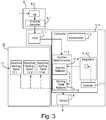
Fig. 3 depicts as a simplified block diagram a decoder according to an example embodiment of the present invention; -
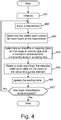
Fig. 4 depicts as a flow diagram an encoding method according to an example embodiment of the present invention; -
Fig. 5 depicts as a flow diagram a decoding method according to an example embodiment of the present invention; -
Fig. 6a depicts an example of a division of a macroblock into smaller blocks; -
Fig. 6b depicts as a tree diagram an example of a hierarchical structure of syntax elements of the macroblock ofFig. 6a ; -
Fig. 6c depicts as a tree diagram another example of a hierarchical structure of syntax elements of a macroblock; -
Figs. 7a-7c depict some examples of macroblocks divided into four subblocks and corresponding coded block pattern values; -
Fig. 8 shows schematically an electronic device employing some embodiments of the invention; -
Fig. 9 shows schematically a user equipment suitable for employing some embodiments of the invention; -
Fig. 10 further shows schematically electronic devices employing embodiments of the invention connected using wireless and wired network connections; -
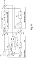
Figure 11 shows schematically an embodiment of a video encoder; -
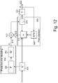
Figure 12 shows a schematic diagram of an embodiment of a video decoder; -
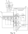
Fig. 13 depicts as a simplified block diagram an encoder according to another example embodiment of the present invention; -
Fig. 14 depicts as a simplified block diagram a decoder according to another example embodiment of the present invention. - The following describes in further detail suitable apparatus and possible mechanisms for the provision of enhancing encoding efficiency and signal fidelity for a video codec. In this regard reference is first made to
Figure 8 which shows a schematic block diagram of an exemplary apparatus orelectronic device 50, which may incorporate a codec according to an embodiment of the invention, and toFigure 9 , which shows schematically a user equipment suitable for employing some embodiments of the invention. - The
electronic device 50 may for example be a mobile terminal or user equipment of a wireless communication system. However, it would be appreciated that embodiments of the invention may be implemented within any electronic device or apparatus which may require encoding and decoding or encoding or decoding video images. - The
apparatus 50 may comprise ahousing 30 for incorporating and protecting the device. Theapparatus 50 further may comprise adisplay 32 in the form of a liquid crystal display. In other embodiments of the invention the display may be any suitable display technology suitable to display an image or video. Theapparatus 50 may further comprise akeypad 34. In other embodiments of the invention any suitable data or user interface mechanism may be employed. For example the user interface may be implemented as a virtual keyboard or data entry system as part of a touch-sensitive display. The apparatus may comprise a microphone 2.3 or any suitable audio input which may be a digital or analogue signal input. Theapparatus 50 may further comprise an audio output device which in embodiments of the invention may be any one of: anearpiece 38, speaker, or an analogue audio or digital audio output connection. Theapparatus 50 may also comprise a battery 40 (or in other embodiments of the invention the device may be powered by any suitable mobile energy device such as solar cell, fuel cell or clockwork generator). The apparatus may further comprise aninfrared port 42 for short range line of sight communication to other devices. In other embodiments theapparatus 50 may further comprise any suitable short range communication solution such as for example a Bluetooth wireless connection or a USB/firewire wired connection. - The
apparatus 50 may comprise a controller 1.4, 11.4 or processor for controlling theapparatus 50. The controller 1.4, 11.4 may be connected tomemory 58 which in embodiments of the invention may store both data in the form of image and audio data and/or may also store instructions for implementation on the controller 1.4, 11.4. The controller 1.4, 11.4 may further be connected tocodec circuitry 54 suitable for carrying out coding and decoding of audio and/or video data or assisting in coding and decoding carried out by the controller 1.4, 11.4. - The
apparatus 50 may further comprise a card reader 48 and asmart card 46, for example a UICC and UICC reader for providing user information and being suitable for providing authentication information for authentication and authorization of the user at a network. - The
apparatus 50 may compriseradio interface circuitry 52 connected to the controller and suitable for generating wireless communication signals for example for communication with a cellular communications network, a wireless communications system or a wireless local area network. Theapparatus 50 may further comprise anantenna 44 connected to theradio interface circuitry 52 for transmitting radio frequency signals generated at theradio interface circuitry 52 to other apparatus(es) and for receiving radio frequency signals from other apparatus(es). - In some embodiments of the invention, the
apparatus 50 comprises a camera capable of recording or detecting individual frames which are then passed to thecodec 54 or controller for processing. In some embodiments of the invention, the apparatus may receive the video image data for processing from another device prior to transmission and/or storage. In some embodiments of the invention, theapparatus 50 may receive either wirelessly or by a wired connection the image for coding/decoding. - With respect to
Figure 10 , an example of a system within which embodiments of the present invention can be utilized is shown. Thesystem 110 comprises multiple communication devices which can communicate through one or more networks. Thesystem 110 may comprise any combination of wired or wireless networks including, but not limited to a wireless cellular telephone network (such as a GSM, UMTS, CDMA network etc), a wireless local area network (WLAN) such as defined by any of the IEEE 802.x standards, a Bluetooth personal area network, an Ethernet local area network, a token ring local area network, a wide area network, and the Internet. - The
system 110 may include both wired and wireless communication devices orapparatus 50 suitable for implementing embodiments of the invention. - For example, the system shown in
Figure 10 shows amobile telephone network 111 and a representation of theinternet 128. Connectivity to theinternet 128 may include, but is not limited to, long range wireless connections, short range wireless connections, and various wired connections including, but not limited to, telephone lines, cable lines, power lines, and similar communication pathways. - The example communication devices shown in the
system 110 may include, but are not limited to, an electronic device orapparatus 50, a combination of a personal digital assistant (PDA) and amobile telephone 114, aPDA 116, an integrated messaging device (IMD) 118, adesktop computer 120, anotebook computer 122. Theapparatus 50 may be stationary or mobile when carried by an individual who is moving. Theapparatus 50 may also be located in a mode of transport including, but not limited to, a car, a truck, a taxi, a bus, a train, a boat, an airplane, a bicycle, a motorcycle or any similar suitable mode of transport. - Some or further apparatus may send and receive calls and messages and communicate with service providers through a wireless connection 25 to a
base station 124. Thebase station 124 may be connected to anetwork server 126 that allows communication between themobile telephone network 111 and theinternet 128. The system may include additional communication devices and communication devices of various types. - The communication devices may communicate using various transmission technologies including, but not limited to, code division multiple access (CDMA), global systems for mobile communications (GSM), universal mobile telecommunications system (UMTS), time divisional multiple access (TDMA), frequency division multiple access (FDMA), transmission control protocol-internet protocol (TCP-IP), short messaging service (SMS), multimedia messaging service (MMS), email, instant messaging service (IMS), Bluetooth, IEEE 802.11 and any similar wireless communication technology. A communications device involved in implementing various embodiments of the present invention may communicate using various media including, but not limited to, radio, infrared, laser, cable connections, and any suitable connection.
- In the following the system of
Fig. 1 will be described in more detail. The information to be encoded and transmitted is received by anencoder 1 from asource 2. The encoder may be a part of a codec of theuser apparatus 50, or it may be a part of another apparatus or it may also be an apparatus of its own. The information can be e.g. video information, audio information, still images, text, etc. The information can also be a combination of two or more different kinds of information. Then, there may be provided different encoders and decoders for each type of information or the same encoder and/or decoder may process different kinds of information. Thesource 2 can be, for example, a video camera 2.1, a still camera 2.2, a microphone 2.3, a device 2.4 capable of playing back e.g. digital versatile disks (DVD), a storage medium 2.5, etc. The above examples of the information and thesource 2 are only for illustrating the present invention, not for limiting the scope of the present invention. The information from thesource 2 is encoded by anencoder 1 of thefirst device 8. The encoded information can be stored to a memory 4 and/or transmitted by atransmitter 9 to atransmission channel 15. The transmitted information can be received by areceiver 114 of asecond device 10. Thesecond device 10 comprises adecoder 11 which decodes the received information. The decoded information can be post-processed, for example, by storing the decoded information to amemory 12 of the second device, displayed by a display, if the information contains visual information, transformed to audio information, if the information contains audio information etc. - With respect to
Figure 11 , a block diagram of a video encoder suitable for carrying out encoding of a video information is shown. -
Figure 11 shows the encoder as comprising apixel predictor 302,prediction error encoder 303 andprediction error decoder 304. - The
pixel predictor 302 receives theimage 300 to be encoded at both the inter-predictor 306 (which determines the difference between the image and a reference frame 318) and the intra-predictor 308 (which determines the image based only on the current frame or picture). The output of both the inter-predictor and the intra-predictor are passed to themode selector 310. Themode selector 310 also receives a copy of theimage 300. The output of the mode selector is the predicted representation of animage block 312 from either the intra-predictor 306 or intra-predictor 308 which is passed to a first summingdevice 321. The first summing device may subtract thepixel predictor 302 output from theimage 300 to produce a firstprediction error signal 320 which is input to theprediction error encoder 303. - The
pixel predictor 302 further receives from apreliminary reconstructor 339 the combination of the prediction representation of theimage block 312 and the output 338 of theprediction error decoder 304. The preliminaryreconstructed image 314 may be passed to the intra-predictor 308 and to afilter 316. Thefilter 316 receiving the preliminary representation may filter the preliminary representation and output a finalreconstructed image 340 which may be saved in areference frame memory 318. Thereference frame memory 318 may be connected to the inter-predictor 306 to be used as the reference image against which theimage 300 is compared in inter-prediction operations. - The operation of the
pixel predictor 302 may be configured to carry out any known pixel prediction algorithm known in the art. - The
prediction error encoder 303 comprises atransform block 351 which performs a transform such as a discrete cosine transform (DCT), a discrete sine transform (DST), or a Karhunen-Loéve transform (KLT) to the coefficient values of the macroblocks. Theprediction error encoder 303 also comprises aquantizer block 353 which performs a quantization operation on the coefficients. The output of theprediction error encoder 303 is passed to theentropy encoder 330 and also to theprediction error decoder 304. - The
entropy encoder 330 receives the output of the prediction error encoder and may perform a suitable entropy encoding/variable length encoding on the signal to provide error detection and correction capability. Theentropy encoder 330 may comprise theencoder 1. - The
prediction error decoder 304 receives the output from theprediction error encoder 303 and performs the opposite processes of theprediction error encoder 303 to produce a decoded prediction error signal 338 which when combined with the prediction representation of theimage block 312 at the second summingdevice 339 produces the preliminaryreconstructed image 314. - An example embodiment of the
encoder 1 is depicted inFig. 2 . Theencoder 1 has an input 1.1 to receive the information to be encoded. If the information is in analogue form it is converted to a digital form by e.g. the analog-to-digital converter 3. The analog-to-digital converter 3 forms samples on the basis of the analogue information. The samples represent the analogue signal at some time intervals. However, the information may already be in the form in which theencoder 1 can process it. Hence, the analog-to-digital converter 3 may not be needed. The samples may be stored to a sample buffer 4.1. - In the system of
Figure 11 the information from theprediction error encoder 303 to be encoded may be provided to the input 1.1 without using the analog-to-digital converter 3 as the quantized coefficients are already in digital form. - In the following, the information to be transmitted is assumed to be visual information. The visual information is provided to the
pixel predictor 302,prediction error encoder 303 andprediction error decoder 304.. As mentioned above, pixel prediction operations may be performed such as intra prediction or inter prediction, to form intra (I) pictures, predicted (P) pictures, and/or bidirectionally predicted (B) pictures. These pictures can be transformed into macroblocks. For example, the block processor 1.7 may use the following transform sizes: 4x4, 8x8, 16x16, 32x32, 64x64 and 128x128. - Information to be transmitted is encoded by the
encoder 1 to form code words. In the following the encoding process is described in more detail with reference to the flow diagram ofFig. 4 and to theencoder 1 ofFig. 2 . It is assumed here that some statistical parameters can be estimated from the information to be encoded. For example, the probability distribution of symbols representing the information may be known or may be estimated by using some criteria. In the present invention two or more different sets of variable length code words are provided from which a variable length code words is selected for a symbol to be encoded. The sets of code words can be thought to form different variable length code word tables 5.1-5.M (VLC tables) in which rows represent mappings from a symbol to a code word. The variable length code word tables are also called as adaptive sorting tables in the specification, There are many possibilities to implement the code word tables in practical applications. This will be discussed in more detail later in the specification. - In some embodiments syntax elements can be coded by using an adaptive sorting table. This can be illustrated with the following non-limiting example. The operation of writing a value of a syntax element X into a bitstream could be performed as follows. It is assumed that the value of the syntax element is Y. In the beginning or at some restoration point a default table or one table among a set of default tables may be selected. It is also possible that a table is not defined in a memory of the device but an algorithm or a function may be used to determine values of elements of a table. For the sake of clarity of the explanation of the sorting operation, it is, however, assumed that the table is stored in a memory. The sorted table is maintained for some syntax elements for improved context adaptation. Let's denote the sorted table corresponding to syntax element X as a one dimensional array sorted table X[i]. The rank of the value Y in the sorted table X is first determined and that rank is coded using variable length coding (VLC). After that, the sorted table is updated so that the value Y will have a lower rank. This can be done by various ways but one possible way is to swap the rank of the value Y with the value locating immediately above the value Y, which has the rank-1 i.e. the rank is one less than the rank of the value Y. The rank of the value corresponding the rank-1 is increased. In other words, the ranks of the value Y and the value above Y are switched.
- In the above example a lowering the rank of the value Y means that the value Y is expected to appear more frequently than some other values. In some other embodiments the operation may be reversed i.e. increasing the rank may indicate an assumption that the value who's rank is increased appears more often than some other values wherein a shorter code word may be mapped for that value. In Table 1 the first alternative is used i.e. the value at the top of Table 1 has the lowest rank and the value at the bottom of Table 1 has the highest rank. Correspondingly, shorter code words can be assigned for values having lower ranks and longer code words can be assigned for values having higher ranks.
- As an example the table X may contain the following values:
Table 1 Syntax element VLC code word A 1 B 010 C 011 D 00100 - If the syntax element to be encoded were C, it would mean that the VLC code word would be 011. The sorting operation discussed above would result that the code words for syntax elements C and B were swapped after determining the code word for the syntax element C. Hence, the rearranged sorting table becomes:
Table 2 Syntax element VLC code word A 1 C 010 B 011 D 00100 - Hence, if the syntax element C were encoded again, the code word 010 would be used to represent the syntax element C and the rank of the syntax element C would be amended again. In this example this would mean that the updated VLC code word for the syntax element C would be 1 and the updated VLC code word for the syntax element A would be 010 as is indicated in Table 3:
Table 3 Syntax element VLC code word C 1 A 010 B 011 D 00100 - Video or other images may be encoded by blocks. For example, a macroblock of size NxN may be divided into four smaller blocks (subblocks) of size N/2 x N/2. Some of the smaller blocks may only contain zero values whereas some other block(s) may contain one or more non-zero values. Coding efficiency might be improved if the
encoder 1 did not need to encode the zero valued blocks but only provided an indication in the bitstream which blocks contain non-zero values (or which blocks contain zero values only). In some embodiments this is performed by forming a coded block pattern for a block which indicates which blocks contain at least one non-zero value (non-zero symbol).Figures 7a-7c depict some examples of macroblocks divided into four subblocks and corresponding coded block pattern values. In the example ofFigure 7a the lower-leftblock 703 of themacroblock 700 contains one or more non-zero values whereas the other threeblocks Figure 7a may be presented as a binary value 0010. In the example ofFigure 7b the upper-leftblock 701 and the lower-leftblock 703 of themacroblock 700 contain one or more non-zero value whereas the other twoblocks Figure 7b may then be presented as a binary value 1010. Correspondingly, in the example ofFigure 7c the upper-leftblock 701 and the lower-right block 704 of themacroblock 700 contain one or more non-zero value whereas the other twoblocks Figure 7c may then be presented as a binary value 1001. In this example thebinary number 1 indicated that a block contains non-zero value(s) and thebinary number 0 indicated that a block only contains zero value(s). It is, however, possible to use different symbols or to use thebinary number 1 to indicate a block with zero values only and to use thebinary number 0 to indicate blocks having non-zero value(s). - The
encoder 1 according to an example embodiment of the present invention performs the encoding as follows. In the beginning of the encoding some variables are initialized to their initial values. This is performed, for example, by the controller 1.4 of the encoder which sets some memory locations to a selected state. These memory locations can be located in the memory 4 or they can be internal to the controller 1.4, for example. In the example embodiment ofFig. 2 the variables are stored into the internal registers 1.4.1 of the controller 1.4. The initialization phase is depicted withblock 401 in the flow diagram ofFig. 4 and with an initialization block 1.3 inFig. 2 . - In the initialization different adaptive sorting tables may be initialized to certain states. For example, mapping code values to code words may be arranged in an ascending order of code values, such as values from 0 to 15. Hence, the
code value 0 is mapped to a first code word, thecode value 1 is mapped to a second code word, etc. - After the initialization phase the encoding can be started and a macroblock can be input to the encoder 1 (block 402). The controller 1.4 may instruct a block processor 1.7 to determine a coded block pattern for the current macroblock (block 403). The controller 1.4 may also instruct the block processor 1.7 to determine a block partitioning for the current macroblock. The coded block pattern value, information on the block partitioning, and information on transform partitioning can be encoded by utilizing adaptive sorting tables 5.1, 5.2, ..., 5.M. This is explained in more detail below.
- In some embodiments the block processor 1.7 receives the coded block pattern, information on the block partitioning, and information on transform block sizes, information on macroblock size from the video encoder wherein block processor 1.7 need not determine the coded block pattern and/or the block partitioning.
- An
encoder 1 may insert in a bitstream an indication of subblocks of a macroblock which contain one or more non-zero values i.e. the above mentioned coded block pattern. Theencoder 1 may receive the coded block pattern values for the macroblocks from the video encoder or theencoder 1 may determine the coded block pattern values. - In order to improve coding efficiency, different sorting tables may be used for the same syntax element, such as the coded block pattern, information on transform blocks, information on motion partitioning, depending on the context. For example, three different sorting tables may be used for each syntax element that is coded with the sorting table. These three sorting tables may be defined for each picture type (I picture, P picture and B picture). In other words, for the above example the sorting table can be given as a two dimensional array sorted table X[ctx][i] where the variable ctx identifies which sorting table is used and the variable i indicates the coded block pattern which should be encoded.
- In the following it is assumed that the coded block pattern (cbp) information is coded using a sorted table CBP[ctx][i] 5.1. The context variable may be computed using the following information: picture type and the transform size of the current block (block 404). The
encoder 1 may receive information on the picture type and/or the hierarchy level of the current block from the video encoder, for example from themode selector 310 or theencoder 1 may determine them. The hierarchy level in a tree structure may refer to a coding tree for transform partitions, a coding tree for motion partitions or a coding tree related to block sizes. It should be noted here that the tree structure or a coding tree need not be actually implemented as certain elements or structures in a device but the tree structure or the coding tree may be illustrated as information on dependencies between different kinds of entities. In other words, there may be some hierarchical dependency rules between the entities. As a non-limiting example there could be a block having the size of 64x64 at a highest level of a tree structure. This level may also be called as a root of the tree structure or the coding tree and the levels below the root may be called nodes and the nodes at a certain hierarchy level may form a set of nodes. The block may be dividable to smaller blocks, e.g. to four 32x32 blocks which all can be thought to represent the next level of the tree structure (four nodes at the second level in this example). Each of these four 32x32 blocks may further be dividable to smaller blocks, e.g. to 16x16 blocks. These 16x16 blocks, the number of which could be between 0 and 16 (= four 32x32 blocks each divided to four smaller 16x16 blocks), could thought to represent the third hierarchy level of the tree structure (0 to 16 nodes at the third level in this example). It can also be mentioned that a term called a distance can be used in connection with hierarchy levels of the tree structure wherein elements of a certain hierarchy level has the same distance from the root. For example, the distance of the second hierarchy level is one from the root (where the root represents the first or the highest hierarchy level). - In the following examples the term coding tree is used as an example of the tree structure.
- Table 4 illustrates an example mapping from picture type-transform size to ctx variable. This way, different sorting tables are maintained for different hierarchy levels in a coding tree which may improve the coding efficiency. This is because the values of syntax elements may be more correlated between the same hierarchy levels of a coding tree and separation of sorting tables exploits this correlation.
- Table 4 illustrates an example of using the picture type and the hierarchy level of coding tree used for transform blocks as context.
Table 4 Picture Type Hierarchy level of a coding tree ctx I PICTURE 0 0 1 1 2 2 3 3 P PICTURE 0 4 1 5 2 6 3 7 B PICTURE 0 8 1 9 2 10 3 11 - For example, if the picture type is an intra picture (I picture) and the hierarchy level of the coding tree is 2, the corresponding context (index) would be 2 when Table 4 is used. Correspondingly, for a block with hierarchy level of 1 in a P picture the context would be 5.
- For simplicity, in the following example it is assumed that the
video encoder 1 supports four hierarchy levels (0,1,2,3). The initial adaptive sorting table may be given as:
tableCBP[ctx][i] =
{ {0,1,2,3,4,5,6,7,8,9,10,11,12,13,14,15},
{0,1,2,3,4,5,6,7,8,9,10,11,12,13,14,15},
{0,1,2,3,4,5,6,7,8,9,10,11,12,13,14,15},
{0,1,2,3,4,5,6,7,8,9,10,11,12,13,14,15},
{0,1,2,3,4,5,6,7,8,9,10,11,12,13,14,15},
{0,1,2,3,4,5,6,7,8,9,10,11,12,13,14,15},
{0,1,2,3,4,5,6,7,8,9,10,11,12,13,14,15},
{0,1,2,3,4,5,6,7,8,9,10,11,12,13,14,15},
{0,1,2,3,4,5,6,7,8,9,10,11,12,13,14,15},
{0,1,2,3,4,5,6,7,8,9,10,11,12,13,14,15},
{0,1,2,3,4,5,6,7,8,9,10,11,12,13,14,15},
{0,1,2,3,4,5,6,7,8,9,10,11,12,13,14,15}}
in which the rows correspond with different picture types and hierarchy levels. In this example the rows correspond with the rows of Table 1, i.e. the first row corresponds with an I picture of size 4x4, the second row corresponds with an I picture of size 8x8, etc. - For example, if the
encoder 1 is to code a coded block pattern (cbp) value of 10 which is 1010 in binary form indicating e.g. that the upper-left and lower-left blocks contain at least one non-zero coefficient. Theencoder 1 determines the context variable ctx by using Table 4, for example. It is now assumed that the coded block pattern is coded in an I picture and the hierarchy level is 1. Hence, the context variable ctx can be determined to be 1 as can be seen from Table 4. The rank ofvalue 10 is also 10 in the corresponding sorted table (tableCBP[ctx][i]) and the rank value can be binarized using a VLC table. Then, the corresponding ordered table is updated and the tableCBP array becomes:
tableCBP[ctx][i] =
{ {0,1,2,3,4,5,6,7,8,9,10,11,12,13,14,15},
{0,1,2,3,4,5,6,7,8,10,9,11, 12,13,14,15},
{0,1,2,3,4,5,6,7,8,9,10,11,12,13,14,15},
{0,1,2,3,4,5,6,7,8,9,10,11,12,13,14,15},
{0,1,2,3,4,5,6,7,8,9,10,11,12,13,14,15},
{0,1,2,3,4,5,6,7,8,9,10,11,12,13,14,15},
{0,1,2,3,4,5,6,7,8,9,10,11,12,13,14,15},
{0,1,2,3,4,5,6,7,8,9,10,11,12,13,14,15},
{0,1,2,3,4,5,6,7,8,9,10,11,12,13,14,15},
{0,1,2,3,4,5,6,7,8,9,10,11,12,13,14,15},
{0,1,2,3,4,5,6,7,8,9,10,11,12,13,14,15},
{0,1,2,3,4,5,6,7,8,9,10,11,12,13,14,15}} - In other words, the
values - It is now supposed that the encoder codes next a coded block pattern value of 3 in an I picture with hierarchy level being equal to 3. The ctx variable is found out to be 3 from Table 4. The rank of
value 3 in the corresponding sorting table is 3, and therank value 3 is binarized using a VLC table. Then the corresponding ordered table is updated and the tableCBP array becomes:
tableCBP[ctx][i] =
{ {0,1,2,3,4,5,6,7,8,9,10,11,12,13,14,15},
{0,1,2,3,4,5,6,7,8,10,9,11,12,13,14,15},
{0,1,2,3,4,5,6,7,8,9,10,11,12,13,14,15},
{0,1,3,2,4,5,6,7,8,9,10,11,12,13,14,15},
{0,1,2,3,4,5,6,7,8,9,10,11,12,13,14,15},
{0,1,2,3,4,5,6,7,8,9,10,11,12,13,14,15},
{0,1,2,3,4,5,6,7,8,9,10,11,12,13,14,15},
{0,1,2,3,4,5,6,7,8,9,10,11,12,13,14,15},
{0,1,2,3,4,5,6,7,8,9,10,11,12,13,14,15},
{0,1,2,3,4,5,6,7,8,9,10,11,12,13,14,15},
{0,1,2,3,4,5,6,7,8,9,10,11,12,13,14,15},
{0,1,2,3,4,5,6,7,8,9,10,11,12,13,14,15}} - The
values - Next, some examples of VLC tables for encoding the rank value are illustrated.
Table 5 Rank VLC code word 0 10 1 11 2 010 3 011 4 00100 5 00101 6 00110 7 00111 8 00010 9 00011 10 0000100 11 0000101 12 0000110 13 0000111 14 0000010 15 0000011 Table 6 Rank VLC code word 0 1 1 010 2 011 3 00010 4 00011 5 00001000 6 00001001 7 00001010 8 00001100 9 00001101 10 00001110 11 00001111 12 00000100 13 00000101 14 00000110 15 00000111 - Using the above example the VLC code word 0000100 would first be selected to encode the coded block pattern value of 10, if Table 5 were used, or the VLC code word 00001110, if Table 6 were used. When the coded block pattern value of 10 is to be encoded again, the update rank for the
value 10 is 9 wherein the VLC word is 00011 (Table 5) or 00001101 (Table 6). - In the second example the
encoder 1 codes a coded block pattern value of 3 in an I picture with hierarchy level being equal to 3. The ctx variable was found out to be 3 from Table 4 wherein the VLC code word would first be 011, if the Table 5 were used, or 00010, if the Table 6 were used. Next time the coded block pattern value of 3 would be binarized as 010 (Table 5) or as 011 (Table 6). - In the
encoder 1 the sorting table selector 1.6 may calculate the index ctx to the adaptive sorting table CBP[ctx][i] and select the correct row in the sorting table by using the index ctx. The sorting table selector 1.6 may then assign the code word from the table to be used to represent the current syntax element by using the value of the syntax element as a pointer to the row in the sorting table (block 405). The sorting table adapter 1.8 may use the same pointer to adapt the sorting table (block 406) as illustrated above e.g. by swapping values of two consecutive elements in the adaptive sorting table. - In another embodiment, illustrated in
Figure 13 , the code word selection may be implemented by using a code word selector 1.9 which may receive information from the sorting table selector 1.6 on the selected sorting table. The code word selector 1.9 may then use the value of the syntax element to select the code word from the selected code word table. - The above procedures can be repeated for other macroblocks or other data to be encoded (block 407).
- In some embodiments macroblocks can be partitioned into smaller blocks using a quad-tree partitioning, for example. An example of partitioning a macroblock into smaller blocks in a quad-tree manner is depicted in
Figures 6a and 6b. Figure 6a depicts an example of amacroblock 600 partitioned intosmaller blocks smaller blocks 611--614, the lower-right block 640 is divided into foursmaller blocks 641--644, and the upper-leftblock 641 of the latter partitioned block 640 (i.e. the lower-right block of the large macroblock 600) is further divided into four smaller blocks 645-648. A quad-tree corresponding to the block partitioning of the example ofFigure 6a is illustrated inFigure 6b . The quad-tree partitioning is a kind of a hierarchical transform. In some embodiments the quad tree can be coded e.g. by usingbinary numbers number 1 may indicate that the block is divided into smaller blocks wherein thenumber 0 may indicate that the block is not divided into smaller blocks. This indication is called as a split flag indicating at each tree-node whether the transform should be splitted further. The quad-tree of the example ofFigure 6b could then be encoded as a set of binary values 1001, 0000, 1000, 0000. The first binary value 1001 represents the first (highest) level of the quad-tree indicating that the first (upper-left) and the last (lower-right) blocks are divided into smaller blocks. The next two binary values 0000 and 1000 represent the second (highest) level of the quad-tree, and the last binary value 0000 represents one part of the third (highest) level of the quad-tree. If some of the other blocks of the second level were divided into smaller blocks, the quad-tree would include at the third level more binary values. In other words, if a binary value at a certain level of the quad-tree includes anumber 1, the binary representation of the quad-tree would contain a binary value at the next lower level. Another example of a quad-tree is illustrated inFigure 6c . The corresponding binary representation of the quad-tree ofFigure 6c might be 1001, 0010, 1000, 0100, 0000, 0000. It should be noted here that the quad-tree may also be represented in a different way, for example in such a way that thebinary number 1 may indicate that the block is not divided into smaller blocks wherein thenumber 0 may indicate that the block is divided into smaller blocks. Also other numbers or characters than thebinary numbers - From the above it can be concluded that partitioning of macroblocks of an image or a slice of an image can be indicated to a decoder by using quad-trees. Therefore, the
encoder 1 may insert an indication of the partitioning of a macroblock into a bitstream by encoding the binary representation of the quad-tree. In the following an example implementation of encoding the binary representation is disclosed. - In some embodiments a macroblock can have a large size (e.g. 128x128 or even larger than that) and can be divided into smaller blocks in the quad-tree manner. The block processor 1.7 of the video encoder, or in some other embodiments the
encoder 1 may examine the contents of the large macroblock and on the basis of the examination may decide to use smaller block sizes for certain areas of the macroblock. The decision may depend on the smoothness of the image contents, the number of details in the area of the macroblock etc. - When the
encoder 1 has received information or determined the partitioning of a macroblock theencoder 1 may encode information on the partitioning e.g. as follows. This information is called as a transform structure information in this context. It should be noted that, in addition to transform structure, similar quad-tree as explained below could be used for block sizes, motion partitions. - In some embodiments a block need not be divided into four smaller blocks of the same size. For example, a MxM block may be divided to two (M/2)xM blocks or two Mx(M/2) blocks. It may also be possible to divide the MxM block to blocks having different sizes. For example, it may be divided to one block of size (M-N)xM and another block of size NxM, to one block of size Mx(M-N) and another block of size MxN, etc. It may also be possible to divide a block to four smaller blocks which need not be the same size. For example, an MxM block may be dividable to one NxN block, one (M-N)x(M-N) block, one (M-N)xN block and one Nx(M-N) block. The above mentioned parameters M, N are positive integers. In some embodiments these kind of block sizes may be used to represent motion partition blocks and the syntax element may then relate to motion partition information.
- Using 1-bit syntax elements may not be coded efficiently using VLC coding, so it may be better to group the syntax elements. A syntax element called transform split pattern (tsp) is used that indicates which one of the four transform blocks are split further. The tsp syntax element may then be coded using adaptive sorting table, similar to the coded block pattern illustrated above.
- It is now assumed that the tsp information is coded using sorted table TSP[ctx][i]. Similar to the coded block pattern coding, the context variable is computed using the following information: the picture type and the transform size of the current block.
- For simplicity, in the following example it is again assumed that the
video encoder 1 supports transforms of sizes 4x4, 8x8, 16x16 and 32x32. In this example, the 32x32 transform size refers to transform codingtree hierarchy level 0, 16x16 refers tohierarchy level 1 and so on. The initial adaptive sorting table for the tsp information may be given as:
tableTSP[ctx][i] =
{ {0,1,2,3,4,5,6,7,8,9,10,11,12,13,14,15},
{0,1,2,3,4,5,6,7,8,9,10,11,12,13,14,15},
{0,1,2,3,4,5,6,7,8,9,10,11,12,13,14,15},
{0,1,2,3,4,5,6,7,8,9,10,11,12,13,14,15},
{0,1,2,3,4,5,6,7,8,9,10,11,12,13,14,15},
{0,1,2,3,4,5,6,7,8,9,10,11,12,13,14,15},
{0,1,2,3,4,5,6,7,8,9,10,11,12,13,14,15},
{0,1,2,3,4,5,6,7,8,9,10,11,12,13,14,15},
{0,1,2,3,4,5,6,7,8,9,10,11,12,13,14,15},
{0,1,2,3,4,5,6,7,8,9,10,11,12,13,14,15},
{0,1,2,3,4,5,6,7,8,9,10,11,12,13,14,15},
{0,1,2,3,4,5,6,7,8,9,10,11,12,13,14,15}}
in which the rows correspond with different picture types and block sizes. In this example the rows correspond with the rows of Table 1, i.e. the first row corresponds with I picture of size 4x4, the second row corresponds with I picture of size 8x8, etc. - In the example of
Figures 6a and 6b the node at the top of the quad-tree corresponds with the size of an unsplitted macroblock. In this case the size is 128x128 picture elements but it can be different from that. That node need not be encoded. The first level (highest in thefigure 6b ) which may have tsp information is the level below the top node, i.e. the four branches from the top node. This level corresponds with theblock size 128/2 x 128/2 = 64 x 64. Hence, if the tsp value 9 (=1001 as a binary number) were to be encoded, Table 4 would indicate that the index ctx were 3, if the macroblock is a macroblock of an I picture, 7, if the macroblock is a macroblock of a P picture, or 11, if the macroblock is a macroblock of a B picture. - If the macroblock belongs to a P picture, the VLC code word could be selected from the eighth row of the table TSP[ctx][i]. The value is 9 so the tenth VLC code word from the eighth row were selected and the rank of the tenth row were amended, e.g. by decreasing the rank by 1. Hence, the table TSP[ctx][i] were amended as follows
tableTSP[ctx][i] =
{ {0,1,2,3,4,5,6,7,8,9,10,11,12,13,14,15},
{0,1,2,3,4,5,6,7,8,9,10,11,12,13,14,15},
{0,1,2,3,4,5,6,7,8,9,10,11,12,13,14,15},
{0,1,2,3,4,5,6,7,8,9,10,11,12,13,14,15},
{0,1,2,3,4,5,6,7,8,9,10,11,12,13,14,15},
{0,1,2,3,4,5,6,7,8,9,10,11,12,13,14,15},
{0,1,2,3,4,5,6,7,8,9,10,11,12,13,14,15},
{0,1,2,3,4,5,6,7,9,8,10,11,12,13,14,15},
{0,1,2,3,4,5,6,7,8,9,10,11,12,13,14,15},
{0,1,2,3,4,5,6,7,8,9,10,11,12,13,14,15},
{0,1,2,3,4,5,6,7,8,9,10,11,12,13,14,15},
{0,1,2,3,4,5,6,7,8,9,10,11,12,13,14,15}} - In the same way the tsp values for lower levels (smaller block sizes such as 16x16, 8x8, 4x4) of the quad-tree can be binarized.
- In some embodiments the whole quad-tree need not always be encoded. For example, some of the lower levels may contain zero values e.g. when no parts of the large macroblock is partitioned into smallest possible block sizes. For example, a macroblock of size 128x128 may have been divided into subblocks of 64x64 picture elements and these subblocks or only part of them may have further been divided into subblocks of 32x32 picture elements and no further division has been made. In this example, it might suffice if only the tsp values of the first and second level were encoded.
- The
encoder 1 may insert in the bitstream an indication which parameters have been encoded. For example, an indication may be provided that certain VLC code words represent the values of coded block patterns or the values of the transform split pattern, for example. This information may also be provided by using other means or these VLC code words may be located in certain locations of a bit stream, for example. - The design of the sorting tables and the code word tables 5.1-5.M can be application specific, e.g. there is not necessarily a single set of tables that works for every use case. However, Tables 1-6 above illustrate one possible table design that might be used.
- In some embodiments the sorting tables and the code word tables are not separate tables but they are combined. In other words, using Tables 4 and 5 the table CBP[ctx][i] could be implemented in a memory of a device so that a certain memory area is reserved for each possible value of the variable ctx i.e. for each row of the table, and this area contains the code words for each possible value of the variable i of that row. When the rank of a value Y is to be changed the code word corresponding to the current rank of the value Y could be swapped with the code word corresponding to the rank of another value Z with which the rank of the value Y should be changed. Using Table 5 as an example a part of the memory area reserved for the table CBP[ctx][i] could initially contain
values value 3 is to be encoded theencoder 1 would assign the code word 011 to represent thevalue 3 and exchange the code words 010 and 011. After that the above referred part of the memory would contain the followingvalues - Also, in the previous examples, the code word was loaded from a pre-defined table that resides in the memory 4, for example. However, in some cases it is possible to generate the code word on-the-fly so that code words do not need to be stored in the memory. When the encoder needs to get a code word it uses the table number and the code word number to generate the code word using a predefined algorithm.
- The storage of the code word tables 5.1-5.M and the adaptive sorting tables can be implemented in many ways. They can be stored e.g. to the memory 4 of the
first device 8. Each row can be stored in consecutive memory locations so that each value has a certain length of bits or so that after each value there is a field separator to separate different columns from each other. It is also possible to store the values of the tables column-by-column. - In the above some principles of the present invention were discussed from the encoder point of view, but decoder implementation is quite similar except that the processing is reversed i.e. the received code word is used to determine the corresponding symbol. This is now explained in more detail with reference to the decoder of
Fig. 3 and the flow diagram ofFig. 5 . The second device 10 (Fig. 1 ) receives the transmitted information and performs in thereceiver 14 e.g. conversion 14.1 of a radio frequency signal to a lower frequency signal (for example to a base band signal), channel decodes 14.2 the lower frequency signal and/or some other operations to obtain code words from the received signal. The received code words can be stored in thememory 12 of the second device for further processing. - The
second device 10 or thedecoder 11 includes the tables corresponding the tables theencoder 1 uses when encoding the coded block pattern and/or the transform split pattern, or the tables may be provided to thedecoder 11 in another way, for example by transmitting them from the first device to the second device, or by downloading them from a storage medium, from a server, etc. - An initialization block 11.3 of a
decoder 11 initializes (block 501 inFig. 5 ) the adaptive sorting tables to an initial state which corresponds with the initial state of the adaptive sorting tables at theencoder 1. Thedecoder 11 has access to tables corresponding the tables of the encoder. For example, thedecoder 11 has a similar set of adaptive sorting tables 17.1-17.M than the adaptive sorting tables 5.1-5.M of theencoder 1. The tables can be formed e.g. in thememory 12 of the decoder or thedecoder 11 can comprise some algorithms to use instead of the tables. - The
decoder 11 may comprise a variable k which indicates the type of the code word, for example if the code word relates to the coded block pattern information, to the transform split pattern information, or if the code word includes information on a coefficient of a block, etc. There may also be other ways to separate different types of code words from each other by thedecoder 11. - The symbol determination block 11.2 may use the current value of the variable k to determine which adaptive sorting table to use (block 502) or there may be a sorting table selector 11.9 for the selection of the adaptive sorting table. For example, if the variable k indicates that the current code word relates to the coded block pattern information, the symbol determination block 11.2 or the sorting table selector 11.9 uses information on the picture type and transform size to select the correct row of the coded block pattern table CBP[ctx][i] and uses the code word to select the correct element in that row.
- The received bits are input e.g. one by one or in larger parts to the input 11.1 of the
decoder 11 from which the bits are delivered to the symbol determination block 11.2 (block 503). The symbol determination block 11.2 examines the code words of the adaptive sorting table 17.1, 17.2, 17.M to determine whether such a code word exists in the adaptive sorting table (blocks 504, 505). If the examination indicates that the code word exists, the code word thus obtained can be used to determine the symbol i.e. the coded block pattern value (block 506). However, if the bit pattern so far decoded is not a code word in the code word table, the next bit is also input and combined with the previous bit(s). When an existing code word has been found, it can be used to determine the correct coded block pattern value. The coded block pattern value can also be stored e.g. to thememory 12 of thesecond device 10. The symbol determination block 11.2 can comprise a symbol selector 11.8 for performing the examination of the code words and corresponding symbols in the adaptive sorting tables.After finding the code word from the input bit stream and the corresponding coded block pattern value, the coded block pattern table CBP[ctx] [i] can be updated e.g. by an adapter 11.6 by increasing the rank of the coded block pattern value as was disclosed in connection with the operation of the encoder (block 507). In case of decoding code words relating to the transform split pattern values the operation is quite similar to above with the exception that the table to be used is the transform split pattern table TSP[ctx][i] corresponding with the transform split pattern table TSP[ctx][i] of the encoder. - In some embodiments, as illustrated in
Figure 14 , thedecoder 11 may comprise a syntax element selector 11.8 which may use the code word to select the correct syntax element in the selected row of the selected sorting table, and an adapter 11.10 for adapting the selected sorting table. - The controller 11.4 can comprise an update element 11.7 for updating the adaptive sorting tables and possibly some other variables.
- It should be noted here that there are also other possibilities to decode the symbol from the code word. It need not happen bit by bit but any kind of method of finding the matching codeword can be utilized in this context. For example, a part of the bit stream is input to the input 11.1 of the
decoder 11 from which the bits are delivered to the symbol determination block 11.2. The symbol determination block 11.2 examines from the selected variable length code word table if said part of the bit stream comprises a code word in said selected variable length code word table. If the examination indicates that said part of the bit stream comprises a code word in said selected variable length code word table, the symbol determination block 11.2 determines which symbol in said selected variable length code word table corresponds with the code word, and outputs the symbol. If the examination indicates that said part of the bit stream does not comprise any code word in said selected variable length code word table, a next part of the bit stream is input to the input 11.1 of thedecoder 11 and delivered to the symbol determination block 11.2 for further examination. The above steps are repeated until a valid code word has been found from the selected variable length code word table. - When the code word and a corresponding syntax element has been found, the syntax element may be provided to further processing by the output 11.6 of he decoder 11. The further processing may include storing the syntax element, reconstructing a block of a image or a whole image, etc.
- There are also other possibilities to find matching code words in the decoding process such as using look-up tables or using binary tree.
- By repeating the process the bit stream is correctly decoded resulting the same symbol stream which was transmitted.
-
Figure 12 shows a block diagram of a video decoder suitable for decoding macroblocks and reconstructing video e.g. for displaying, for storing or for further processing. The video decoder shows anentropy decoder 600 which performs an entropy decoding on the received signal and may comprise thedecoder 11 described above. The entropy decoder thus performs the inverse operation to theentropy encoder 330 of the encoder described above. Theentropy decoder 600 outputs the results of the entropy decoding to aprediction error decoder 602 andpixel predictor 604. - The
pixel predictor 604 receives the output of theentropy decoder 600 and apredictor selector 614 within thepixel predictor 604 determines that either an intra-prediction or an inter-prediction operation is to be carried out. The predictor selector furthermore outputs a predicted representation of animage block 616 to afirst combiner 613. The predicted representation of theimage block 616 is used in conjunction with the reconstructedprediction error signal 612 to generate a preliminaryreconstructed image 618. The preliminaryreconstructed image 618 may be used in thepredictor 614 or may be passed to afilter 620. Thefilter 620 applies a filtering which outputs a final predicted signal 622. The final predicted signal 622 may be stored in areference frame memory 624, thereference frame memory 624 further being connected to thepredictor 614 for prediction operations. - The
prediction error decoder 602 receives the output of theentropy decoder 600 and performs inverse transformation by theinverse transformation block 692 and inverse quantization by theinverse quantizer 693 to obtain the reconstructedprediction error signal 612. - In the above examples the functional elements of the
encoder 1 and thedecoder 11 were depicted as separate blocks. However, in practical implementations the functional elements or some of them can be implemented in hardware or as a program code of the controller 1.4 of theencoder 1 and/or the controller 11.4 of thedecoder 11. The controllers 1.4, 11.4 can be digital signal processors or other processors comprising program code interpreter or other means for executing program code. The program code can be stored into a storage medium such as thememory 4, 12 or into a disk e.g. a CDROM, or to another kind of a carrier. - The invention can be used in applications that use data compression, for example to compress video signals. In video coding, it has been observed that the method is beneficial for coding at least a macroblock mode, a coded block pattern (cbp) and position of the last non-zero coefficient in discrete cosine transform (DCT) transformed block.
- The present invention can also be utilized in encoding information on the position of the last non-zero coefficient in discrete cosine transform (DCT) transformed block. The VLC code word may then be selected n the basis of an adaptive sorting table depending on e.g. the picture type and the transform size of the current block.
- The
first device 8 comprising theencoder 1 can be, for example, a wireless communication device, a computer, a server, a CDROM player, a DVD player, etc. Thesecond device 10 comprising thedecoder 11 can be, for example, a wireless communication device, a computer, a server, a CDROM player, a DVD player, etc. Thetransmission channel 15 can comprise a communication network such as a wireless communication network, a local area network, a wired or a wireless connection between thefirst device 9 and thesecond device 10, etc. - The embodiments of the invention described above describe the codec in terms of separate encoder and decoder apparatus in order to assist the understanding of the processes involved. However, it would be appreciated that the apparatus, structures and operations may be implemented as a single encoder-decoder apparatus/structure/operation. Furthermore in some embodiments of the invention the coder and decoder may share some or all common elements.
- Although the above examples describe embodiments of the invention operating within a codec within an electronic device, it would be appreciated that the invention as described below may be implemented as part of any video codec. Thus, for example, embodiments of the invention may be implemented in a video codec which may implement video coding over fixed or wired communication paths.
- Thus, user equipment may comprise a video codec such as those described in embodiments of the invention above.
- It shall be appreciated that the term user equipment is intended to cover any suitable type of wireless user equipment, such as mobile telephones, portable data processing devices or portable web browsers.
- Furthermore elements of a public land mobile network (PLMN) may also comprise video codecs as described above.
- In general, the various embodiments of the invention may be implemented in hardware or special purpose circuits, software, logic or any combination thereof. For example, some aspects may be implemented in hardware, while other aspects may be implemented in firmware or software which may be executed by a controller, microprocessor or other computing device, although the invention is not limited thereto. While various aspects of the invention may be illustrated and described as block diagrams, flow charts, or using some other pictorial representation, it is well understood that these blocks, apparatus, systems, techniques or methods described herein may be implemented in, as non-limiting examples, hardware, software, firmware, special purpose circuits or logic, general purpose hardware or controller or other computing devices, or some combination thereof.
- The embodiments of this invention may be implemented by computer software executable by a data processor of the mobile device, such as in the processor entity, or by hardware, or by a combination of software and hardware. Further in this regard it should be noted that any blocks of the logic flow as in the Figures may represent program steps, or interconnected logic circuits, blocks and functions, or a combination of program steps and logic circuits, blocks and functions. The software may be stored on such physical media as memory chips, or memory blocks implemented within the processor, magnetic media such as hard disk or floppy disks, and optical media such as for example DVD and the data variants thereof, CD.
- The memory may be of any type suitable to the local technical environment and may be implemented using any suitable data storage technology, such as semiconductor based memory devices, magnetic memory devices and systems, optical memory devices and systems, fixed memory and removable memory. The data processors may be of any type suitable to the local technical environment, and may include one or more of general purpose computers, special purpose computers, microprocessors, digital signal processors (DSPs) and processors based on multi core processor architecture, as non limiting examples.
- Embodiments of the inventions may be practiced in various components such as integrated circuit modules. The design of integrated circuits is by and large a highly automated process. Complex and powerful software tools are available for converting a logic level design into a semiconductor circuit design ready to be etched and formed on a semiconductor substrate.
- Programs, such as those provided by Synopsys, Inc. of Mountain View, California and Cadence Design, of San Jose, California automatically route conductors and locate components on a semiconductor chip using well established rules of design as well as libraries of pre stored design modules. Once the design for a semiconductor circuit has been completed, the resultant design, in a standardized electronic format (e.g., Opus, GDSII, or the like) may be transmitted to a semiconductor fabrication facility or "fab" for fabrication.
Claims (12)
- A method comprising:receiving a syntax element to be encoded as a code word, wherein the syntax element relates to at least one of a coded block pattern, a transform split pattern, or motion partition information;selecting the code word for the syntax element on the basis of a hierarchy level in a tree structure, wherein the hierarchy level identifies a distance of a node from a root node of the tree structure, and the syntax element is associated with the node, wherein the tree structure relates to at least one of a transform block size, a prediction block size, or a block size; andupdating a mapping from syntax elements to code words for encoding subsequent values of the syntax element.
- The method according to claim 1, wherein the tree structure is a quad-tree.
- The method according to claim 1 or 2, wherein selecting the code word for the syntax element comprises:
selecting a context for context adaptive binary arithmetic coding. - A method comprising:receiving a code word of a set of code words;determining a hierarchy level in a tree structure, wherein the hierarchy level identifies a distance of a node from a root node of the tree structure, wherein the tree structure relates to at least one of a transform block size, a prediction block size, or a block size;obtaining a syntax element associated with the node on the basis of the code word and said hierarchy level, wherein the syntax element relates to at least one of a coded block pattern, a transform split pattern, or motion partition information; andupdating a mapping from code words to syntax elements for decoding subsequent values of the code word.
- The method according to claim 4, wherein the tree structure is a quad tree.
- The method according to claim 4 or 7, wherein the code word is a context for context adaptive binary arithmetic coding.
- An apparatus comprising:means for receiving a syntax element to be encoded as a code word of a set of code words, wherein the syntax element relates to at least one of a coded block pattern, a transform split pattern, or motion partition information;means for selecting the code word for the syntax element on the basis of a hierarchy level in a tree structure, wherein the hierarchy level identifies a distance of a node from a root node of the tree structure, and the syntax element is associated with the node, wherein the tree structure relates to at least one of a transform block size, a prediction block size, or a block size; andmeans for updating a mapping from syntax elements to code words for encoding subsequent values of the syntax element.
- The apparatus according to claim 7, wherein the tree structure is a quad-tree.
- The apparatus according to claim 7 or 8, wherein the means for selecting the code word for the syntax element comprises:
means for selecting a context for context adaptive binary arithmetic coding. - An apparatus comprising:means for receiving a code word of a set of code words;means for determining a hierarchy level in a tree structure, wherein the hierarchy level identifies a distance of a node from a root node of the tree structure, wherein the tree structure relates to at least one of a transform block size, a prediction block size, or a block size;means for obtaining a syntax element associated with the node on the basis of the code word and said hierarchy level, wherein the syntax element relates to at least one of a coded block pattern, a transform split pattern, or motion partition information; andmeans for updating a mapping from code words to syntax elements for decoding subsequent values of the code word.
- The apparatus according to claim 10, wherein the tree structure is a quad tree.
- The apparatus according to claim 10 or 11, wherein the code word is a context for context adaptive binary arithmetic coding.
Applications Claiming Priority (3)
| Application Number | Priority Date | Filing Date | Title |
|---|---|---|---|
| US36168310P | 2010-07-06 | 2010-07-06 | |
| PCT/IB2011/053008 WO2012023061A1 (en) | 2010-07-06 | 2011-07-06 | Method and apparatus for determining mapping between a syntax element and a code word for variable length coding |
| EP11817837.5A EP2591605B1 (en) | 2010-07-06 | 2011-07-06 | Method and apparatus for determining mapping between a syntax element and a code word for variable length coding |
Related Parent Applications (2)
| Application Number | Title | Priority Date | Filing Date |
|---|---|---|---|
| EP11817837.5A Division-Into EP2591605B1 (en) | 2010-07-06 | 2011-07-06 | Method and apparatus for determining mapping between a syntax element and a code word for variable length coding |
| EP11817837.5A Division EP2591605B1 (en) | 2010-07-06 | 2011-07-06 | Method and apparatus for determining mapping between a syntax element and a code word for variable length coding |
Publications (1)
| Publication Number | Publication Date |
|---|---|
| EP3554075A1 true EP3554075A1 (en) | 2019-10-16 |
Family
ID=45604818
Family Applications (2)
| Application Number | Title | Priority Date | Filing Date |
|---|---|---|---|
| EP11817837.5A Active EP2591605B1 (en) | 2010-07-06 | 2011-07-06 | Method and apparatus for determining mapping between a syntax element and a code word for variable length coding |
| EP19176919.9A Pending EP3554075A1 (en) | 2010-07-06 | 2011-07-06 | Method and apparatus for coding and decoding video using adative sorting tables |
Family Applications Before (1)
| Application Number | Title | Priority Date | Filing Date |
|---|---|---|---|
| EP11817837.5A Active EP2591605B1 (en) | 2010-07-06 | 2011-07-06 | Method and apparatus for determining mapping between a syntax element and a code word for variable length coding |
Country Status (7)
| Country | Link |
|---|---|
| US (1) | US8576097B2 (en) |
| EP (2) | EP2591605B1 (en) |
| KR (1) | KR101497845B1 (en) |
| CN (1) | CN103069801B (en) |
| RU (1) | RU2565877C2 (en) |
| WO (1) | WO2012023061A1 (en) |
| ZA (1) | ZA201300915B (en) |
Families Citing this family (12)
| Publication number | Priority date | Publication date | Assignee | Title |
|---|---|---|---|---|
| JP5368631B2 (en) | 2010-04-08 | 2013-12-18 | 株式会社東芝 | Image encoding method, apparatus, and program |
| CN103238321B (en) * | 2010-09-30 | 2016-11-02 | 三星电子株式会社 | For the symbol of hierarchy being carried out video coding-decoding method and the device thereof of encoding and decoding |
| KR101955374B1 (en) * | 2011-06-30 | 2019-05-31 | 에스케이 텔레콤주식회사 | Method and Apparatus for Image Encoding/Decoding By Fast Coding Unit Mode Decision |
| CN103202020B (en) | 2011-07-29 | 2017-02-08 | 太阳专利托管公司 | Video decoding method and video decoding apparatus |
| EP2988511A1 (en) | 2011-08-04 | 2016-02-24 | MediaTek Inc. | Method and apparatus for reordered binarization of syntax elements in cabac |
| US10412414B2 (en) | 2012-08-13 | 2019-09-10 | Gurulogic Microsystems Oy | Decoder and method for decoding encoded input data containing a plurality of blocks or packets |
| GB2505169B (en) * | 2012-08-13 | 2016-03-16 | Gurulogic Microsystems Oy | decoder and method |
| US9735812B2 (en) * | 2015-06-26 | 2017-08-15 | Intel IP Corporation | Digital RF receiver power saving with signal quality dependent word length reduction |
| CN112601085A (en) | 2017-06-28 | 2021-04-02 | 华为技术有限公司 | Image data encoding and decoding methods and devices |
| WO2019105536A1 (en) * | 2017-11-28 | 2019-06-06 | Huawei Technologies Co., Ltd. | Syntax prediction using reconstructed samples |
| CN109462762B (en) * | 2018-10-26 | 2020-12-01 | 国网福建省电力有限公司漳州供电公司 | Image processing method for unmanned aerial vehicle aerial photography |
| US20240048641A1 (en) * | 2022-08-05 | 2024-02-08 | Samsung Display Co., Ltd. | System and method for dynamic entropy coding |
Family Cites Families (12)
| Publication number | Priority date | Publication date | Assignee | Title |
|---|---|---|---|---|
| US4816914A (en) * | 1987-01-07 | 1989-03-28 | Pictel Corporation | Method and apparatus for efficiently encoding and decoding image sequences |
| US4916914A (en) * | 1988-05-27 | 1990-04-17 | Cpi Engineering Services, Inc. | Rotary displacement compression heat transfer systems incorporating highly fluorinated refrigerant-synthetic oil lubricant compositions |
| CA2110264C (en) | 1991-06-04 | 2002-05-28 | Chong U. Lee | Adaptive block size image compression method and system |
| US6941511B1 (en) * | 2000-08-31 | 2005-09-06 | International Business Machines Corporation | High-performance extensible document transformation |
| ATE439704T1 (en) * | 2002-04-02 | 2009-08-15 | Nokia Corp | CODING OF TRANSFORMATION COEFFICIENTS IN IMAGE/VIDEO CODERS AND/OR DECODERS |
| US6900748B2 (en) * | 2003-07-17 | 2005-05-31 | Fraunhofer-Gesellschaft Zur Foerderung Der Angewandten Forschung E.V. | Method and apparatus for binarization and arithmetic coding of a data value |
| US7199735B1 (en) * | 2005-08-25 | 2007-04-03 | Mobilygen Corporation | Method and apparatus for entropy coding |
| CN100466739C (en) * | 2005-10-12 | 2009-03-04 | 华为技术有限公司 | CABAC decoding system and method |
| US8335261B2 (en) * | 2007-01-08 | 2012-12-18 | Qualcomm Incorporated | Variable length coding techniques for coded block patterns |
| US7443318B2 (en) * | 2007-03-30 | 2008-10-28 | Hong Kong Applied Science And Technology Research Institute Co. Ltd. | High speed context memory implementation for H.264 |
| US8041746B2 (en) * | 2007-10-30 | 2011-10-18 | Sap Ag | Mapping schemas using a naming rule |
| US20100086031A1 (en) | 2008-10-03 | 2010-04-08 | Qualcomm Incorporated | Video coding with large macroblocks |
-
2011
- 2011-07-06 RU RU2013104941/08A patent/RU2565877C2/en active
- 2011-07-06 WO PCT/IB2011/053008 patent/WO2012023061A1/en active Application Filing
- 2011-07-06 KR KR1020137003027A patent/KR101497845B1/en active IP Right Grant
- 2011-07-06 CN CN201180039886.5A patent/CN103069801B/en active Active
- 2011-07-06 EP EP11817837.5A patent/EP2591605B1/en active Active
- 2011-07-06 US US13/177,126 patent/US8576097B2/en active Active
- 2011-07-06 EP EP19176919.9A patent/EP3554075A1/en active Pending
-
2013
- 2013-02-04 ZA ZA2013/00915A patent/ZA201300915B/en unknown
Non-Patent Citations (5)
| Title |
|---|
| DAVIES (BBC) T ET AL: "Suggestion for a Test Model", 1. JCT-VC MEETING; 15-4-2010 - 23-4-2010; DRESDEN; (JOINTCOLLABORATIVE TEAM ON VIDEO CODING OF ISO/IEC JTC1/SC29/WG11 AND ITU-TSG.16 ); URL: HTTP://WFTP3.ITU.INT/AV-ARCH/JCTVC-SITE/,, 7 May 2010 (2010-05-07), XP030007526, ISSN: 0000-0049 * |
| DAVIES T ET AL.: "Suggestion for a Test Model", 1. JCT-VC MEETING; 15-4-2010- 23-4-201 0; DRESDEN; (JOINTCOLLABORATIVE TEAM ON VIDEO CODING OF ISO/IEC JTC1/SC29/WG11 AND ITU-TSG.16, 7 May 2010 (2010-05-07), Retrieved from the Internet <URL:HTTP://WFTP3.ITU.INT/AV-ARCH/JCTVC-SITE> |
| LEE S ET AL: "Efficient coefficient coding method for large transform in VLC mode", 94. MPEG MEETING; 11-10-2010 - 15-10-2010; GUANGZHOU; (MOTION PICTURE EXPERT GROUP OR ISO/IEC JTC1/SC29/WG11),, no. M18248, 5 October 2010 (2010-10-05), XP030046838 * |
| UGUR (NOKIA) K ET AL: "Description of video coding technology proposal by Tandberg, Nokia, Ericsson", 1. JCT-VC MEETING; 15-4-2010 - 23-4-2010; DRESDEN; (JOINT COLLABORATIVE TEAM ON VIDEO CODING OF ISO/IEC JTC1/SC29/WG11 AND ITU-T SG.16 ); URL: HTTP://WFTP3.ITU.INT/AV-ARCH/JCTVC-SITE/,, no. JCTVC-A119, 12 April 2010 (2010-04-12), XP030009029 * |
| UGUR K ET AL.: "Description of video coding technology proposal by Tandberg, Nokia, Ericsson", 1. JCT-VC MEETING; 15-4-2010- 23-4-201 0; DRESDEN; (JOINT COLLABORATIVE TEAM ON VIDEO CODING OF ISO/IEC JTC1/SC29/WG11 AND ITU-T SG.16, 12 April 2010 (2010-04-12), Retrieved from the Internet <URL:HTTP://WFTP3.1TU.INT/AV-ARCH/JCTVC-SITE> |
Also Published As
| Publication number | Publication date |
|---|---|
| EP2591605A1 (en) | 2013-05-15 |
| US8576097B2 (en) | 2013-11-05 |
| KR101497845B1 (en) | 2015-03-02 |
| RU2013104941A (en) | 2014-10-20 |
| US20120169519A1 (en) | 2012-07-05 |
| CN103069801A (en) | 2013-04-24 |
| RU2565877C2 (en) | 2015-10-20 |
| EP2591605B1 (en) | 2019-11-06 |
| WO2012023061A1 (en) | 2012-02-23 |
| CN103069801B (en) | 2016-06-01 |
| KR20130030299A (en) | 2013-03-26 |
| EP2591605A4 (en) | 2016-11-30 |
| ZA201300915B (en) | 2014-07-30 |
Similar Documents
| Publication | Publication Date | Title |
|---|---|---|
| EP2591605B1 (en) | Method and apparatus for determining mapping between a syntax element and a code word for variable length coding | |
| KR101854066B1 (en) | Method and technical equipment for video encoding and decoding | |
| US9838692B2 (en) | Detecting availabilities of neighboring video units for video coding | |
| EP3570545B1 (en) | Low-complexity intra prediction for video coding | |
| EP3300365B1 (en) | Encoding and decoding videos sharing sao parameters according to a color component | |
| JP6231109B2 (en) | Context derivation for context-adaptive, multilevel significance coding | |
| JP5590133B2 (en) | Moving picture coding apparatus, moving picture coding method, moving picture coding computer program, moving picture decoding apparatus, moving picture decoding method, and moving picture decoding computer program | |
| KR101215682B1 (en) | Video coding using spatially varying transform | |
| US20110243245A1 (en) | Variable length coding method and variable length decoding method | |
| KR20170051540A (en) | 32-point transform for media data coding | |
| CN102870411A (en) | An apparatus, a method and a computer program for video processing | |
| US10277917B2 (en) | Video encoding method and apparatus and video decoding method and apparatus | |
| KR20160056901A (en) | Methods, apparatuses and computer programs for video coding | |
| WO2013057375A1 (en) | Method for coding and an apparatus | |
| US10349052B2 (en) | Method for coding and an apparatus | |
| CN113728632A (en) | Video coding and decoding method and system | |
| US20140269896A1 (en) | Multi-Frame Compression | |
| KR20100074272A (en) | Fixed-point implementation of an adaptive image filter with high coding efficiency | |
| CN113785565B (en) | Video encoding and decoding method and system | |
| CN113767636B (en) | Method and system for intra-mode encoding and decoding | |
| WO2017013306A1 (en) | Method and apparatus for encoding and decoding images | |
| CN113785565A (en) | Method and system for video coding and decoding | |
| JP2022526839A (en) | Video decoding method and video decoding system |
Legal Events
| Date | Code | Title | Description |
|---|---|---|---|
| PUAI | Public reference made under article 153(3) epc to a published international application that has entered the european phase |
Free format text: ORIGINAL CODE: 0009012 |
|
| STAA | Information on the status of an ep patent application or granted ep patent |
Free format text: STATUS: THE APPLICATION HAS BEEN PUBLISHED |
|
| AC | Divisional application: reference to earlier application |
Ref document number: 2591605 Country of ref document: EP Kind code of ref document: P |
|
| AK | Designated contracting states |
Kind code of ref document: A1 Designated state(s): AL AT BE BG CH CY CZ DE DK EE ES FI FR GB GR HR HU IE IS IT LI LT LU LV MC MK MT NL NO PL PT RO RS SE SI SK SM TR |
|
| STAA | Information on the status of an ep patent application or granted ep patent |
Free format text: STATUS: REQUEST FOR EXAMINATION WAS MADE |
|
| 17P | Request for examination filed |
Effective date: 20200416 |
|
| RBV | Designated contracting states (corrected) |
Designated state(s): AL AT BE BG CH CY CZ DE DK EE ES FI FR GB GR HR HU IE IS IT LI LT LU LV MC MK MT NL NO PL PT RO RS SE SI SK SM TR |
|
| STAA | Information on the status of an ep patent application or granted ep patent |
Free format text: STATUS: EXAMINATION IS IN PROGRESS |
|
| 17Q | First examination report despatched |
Effective date: 20200623 |
|
| STAA | Information on the status of an ep patent application or granted ep patent |
Free format text: STATUS: EXAMINATION IS IN PROGRESS |