EP3554061A1 - In-vehicle communication device and method - Google Patents
In-vehicle communication device and method Download PDFInfo
- Publication number
- EP3554061A1 EP3554061A1 EP16923997.7A EP16923997A EP3554061A1 EP 3554061 A1 EP3554061 A1 EP 3554061A1 EP 16923997 A EP16923997 A EP 16923997A EP 3554061 A1 EP3554061 A1 EP 3554061A1
- Authority
- EP
- European Patent Office
- Prior art keywords
- layer
- antenna
- signal
- camera
- metal body
- Prior art date
- Legal status (The legal status is an assumption and is not a legal conclusion. Google has not performed a legal analysis and makes no representation as to the accuracy of the status listed.)
- Granted
Links
- 238000004891 communication Methods 0.000 title description 34
- 238000000034 method Methods 0.000 title description 9
- 229910052751 metal Inorganic materials 0.000 claims abstract description 77
- 239000002184 metal Substances 0.000 claims abstract description 77
- 230000005672 electromagnetic field Effects 0.000 claims abstract description 42
- 238000012545 processing Methods 0.000 claims description 19
- 230000000644 propagated effect Effects 0.000 claims description 11
- 239000004020 conductor Substances 0.000 claims description 10
- 238000012546 transfer Methods 0.000 claims description 9
- 239000003989 dielectric material Substances 0.000 claims description 6
- 229920000049 Carbon (fiber) Polymers 0.000 claims description 5
- RYGMFSIKBFXOCR-UHFFFAOYSA-N Copper Chemical compound [Cu] RYGMFSIKBFXOCR-UHFFFAOYSA-N 0.000 claims description 5
- -1 acryl Chemical group 0.000 claims description 5
- 239000004917 carbon fiber Substances 0.000 claims description 5
- 229910052802 copper Inorganic materials 0.000 claims description 5
- 239000010949 copper Substances 0.000 claims description 5
- 239000000463 material Substances 0.000 claims description 5
- VNWKTOKETHGBQD-UHFFFAOYSA-N methane Chemical compound C VNWKTOKETHGBQD-UHFFFAOYSA-N 0.000 claims description 5
- 229920000515 polycarbonate Polymers 0.000 claims description 5
- 239000004417 polycarbonate Substances 0.000 claims description 5
- 230000005291 magnetic effect Effects 0.000 abstract description 30
- 230000005540 biological transmission Effects 0.000 description 16
- 230000035699 permeability Effects 0.000 description 11
- 238000010586 diagram Methods 0.000 description 9
- 239000003302 ferromagnetic material Substances 0.000 description 9
- 230000005684 electric field Effects 0.000 description 8
- XEEYBQQBJWHFJM-UHFFFAOYSA-N Iron Chemical compound [Fe] XEEYBQQBJWHFJM-UHFFFAOYSA-N 0.000 description 6
- 229910000831 Steel Inorganic materials 0.000 description 6
- 239000010959 steel Substances 0.000 description 6
- 239000002889 diamagnetic material Substances 0.000 description 5
- 239000007769 metal material Substances 0.000 description 5
- 239000000615 nonconductor Substances 0.000 description 5
- 230000008569 process Effects 0.000 description 5
- 230000008859 change Effects 0.000 description 4
- 239000000696 magnetic material Substances 0.000 description 4
- 239000002907 paramagnetic material Substances 0.000 description 4
- 229910052742 iron Inorganic materials 0.000 description 3
- 238000012360 testing method Methods 0.000 description 3
- 238000005553 drilling Methods 0.000 description 2
- 230000006698 induction Effects 0.000 description 2
- 238000012986 modification Methods 0.000 description 2
- 230000004048 modification Effects 0.000 description 2
- 230000008054 signal transmission Effects 0.000 description 2
- 229910052782 aluminium Inorganic materials 0.000 description 1
- XAGFODPZIPBFFR-UHFFFAOYSA-N aluminium Chemical compound [Al] XAGFODPZIPBFFR-UHFFFAOYSA-N 0.000 description 1
- 230000015572 biosynthetic process Effects 0.000 description 1
- 238000001514 detection method Methods 0.000 description 1
- 238000011161 development Methods 0.000 description 1
- 230000000694 effects Effects 0.000 description 1
- 238000005516 engineering process Methods 0.000 description 1
- 239000000446 fuel Substances 0.000 description 1
- 230000001939 inductive effect Effects 0.000 description 1
- 238000009434 installation Methods 0.000 description 1
- 238000004519 manufacturing process Methods 0.000 description 1
- 238000012544 monitoring process Methods 0.000 description 1
- 229910000595 mu-metal Inorganic materials 0.000 description 1
- 239000003973 paint Substances 0.000 description 1
- 239000002952 polymeric resin Substances 0.000 description 1
- 230000009467 reduction Effects 0.000 description 1
- 229910052709 silver Inorganic materials 0.000 description 1
- 239000004332 silver Substances 0.000 description 1
- 230000005236 sound signal Effects 0.000 description 1
- 229920003002 synthetic resin Polymers 0.000 description 1
- 239000013585 weight reducing agent Substances 0.000 description 1
- 238000004804 winding Methods 0.000 description 1
Images


Classifications
-
- H—ELECTRICITY
- H01—ELECTRIC ELEMENTS
- H01Q—ANTENNAS, i.e. RADIO AERIALS
- H01Q21/00—Antenna arrays or systems
- H01Q21/06—Arrays of individually energised antenna units similarly polarised and spaced apart
- H01Q21/061—Two dimensional planar arrays
- H01Q21/065—Patch antenna array
-
- B—PERFORMING OPERATIONS; TRANSPORTING
- B60—VEHICLES IN GENERAL
- B60R—VEHICLES, VEHICLE FITTINGS, OR VEHICLE PARTS, NOT OTHERWISE PROVIDED FOR
- B60R16/00—Electric or fluid circuits specially adapted for vehicles and not otherwise provided for; Arrangement of elements of electric or fluid circuits specially adapted for vehicles and not otherwise provided for
- B60R16/02—Electric or fluid circuits specially adapted for vehicles and not otherwise provided for; Arrangement of elements of electric or fluid circuits specially adapted for vehicles and not otherwise provided for electric constitutive elements
- B60R16/023—Electric or fluid circuits specially adapted for vehicles and not otherwise provided for; Arrangement of elements of electric or fluid circuits specially adapted for vehicles and not otherwise provided for electric constitutive elements for transmission of signals between vehicle parts or subsystems
-
- B—PERFORMING OPERATIONS; TRANSPORTING
- B60—VEHICLES IN GENERAL
- B60R—VEHICLES, VEHICLE FITTINGS, OR VEHICLE PARTS, NOT OTHERWISE PROVIDED FOR
- B60R16/00—Electric or fluid circuits specially adapted for vehicles and not otherwise provided for; Arrangement of elements of electric or fluid circuits specially adapted for vehicles and not otherwise provided for
- B60R16/02—Electric or fluid circuits specially adapted for vehicles and not otherwise provided for; Arrangement of elements of electric or fluid circuits specially adapted for vehicles and not otherwise provided for electric constitutive elements
- B60R16/03—Electric or fluid circuits specially adapted for vehicles and not otherwise provided for; Arrangement of elements of electric or fluid circuits specially adapted for vehicles and not otherwise provided for electric constitutive elements for supply of electrical power to vehicle subsystems or for
-
- H—ELECTRICITY
- H02—GENERATION; CONVERSION OR DISTRIBUTION OF ELECTRIC POWER
- H02J—CIRCUIT ARRANGEMENTS OR SYSTEMS FOR SUPPLYING OR DISTRIBUTING ELECTRIC POWER; SYSTEMS FOR STORING ELECTRIC ENERGY
- H02J50/00—Circuit arrangements or systems for wireless supply or distribution of electric power
- H02J50/005—Mechanical details of housing or structure aiming to accommodate the power transfer means, e.g. mechanical integration of coils, antennas or transducers into emitting or receiving devices
-
- H—ELECTRICITY
- H02—GENERATION; CONVERSION OR DISTRIBUTION OF ELECTRIC POWER
- H02J—CIRCUIT ARRANGEMENTS OR SYSTEMS FOR SUPPLYING OR DISTRIBUTING ELECTRIC POWER; SYSTEMS FOR STORING ELECTRIC ENERGY
- H02J50/00—Circuit arrangements or systems for wireless supply or distribution of electric power
- H02J50/10—Circuit arrangements or systems for wireless supply or distribution of electric power using inductive coupling
-
- H—ELECTRICITY
- H04—ELECTRIC COMMUNICATION TECHNIQUE
- H04B—TRANSMISSION
- H04B5/00—Near-field transmission systems, e.g. inductive loop type
-
- H04B5/26—
-
- H04B5/43—
-
- H04B5/72—
-
- H04B5/79—
-
- H—ELECTRICITY
- H04—ELECTRIC COMMUNICATION TECHNIQUE
- H04B—TRANSMISSION
- H04B7/00—Radio transmission systems, i.e. using radiation field
- H04B7/02—Diversity systems; Multi-antenna system, i.e. transmission or reception using multiple antennas
- H04B7/04—Diversity systems; Multi-antenna system, i.e. transmission or reception using multiple antennas using two or more spaced independent antennas
- H04B7/06—Diversity systems; Multi-antenna system, i.e. transmission or reception using multiple antennas using two or more spaced independent antennas at the transmitting station
- H04B7/0613—Diversity systems; Multi-antenna system, i.e. transmission or reception using multiple antennas using two or more spaced independent antennas at the transmitting station using simultaneous transmission
-
- H—ELECTRICITY
- H04—ELECTRIC COMMUNICATION TECHNIQUE
- H04N—PICTORIAL COMMUNICATION, e.g. TELEVISION
- H04N23/00—Cameras or camera modules comprising electronic image sensors; Control thereof
- H04N23/50—Constructional details
- H04N23/52—Elements optimising image sensor operation, e.g. for electromagnetic interference [EMI] protection or temperature control by heat transfer or cooling elements
-
- H—ELECTRICITY
- H04—ELECTRIC COMMUNICATION TECHNIQUE
- H04N—PICTORIAL COMMUNICATION, e.g. TELEVISION
- H04N23/00—Cameras or camera modules comprising electronic image sensors; Control thereof
- H04N23/50—Constructional details
- H04N23/53—Constructional details of electronic viewfinders, e.g. rotatable or detachable
- H04N23/531—Constructional details of electronic viewfinders, e.g. rotatable or detachable being rotatable or detachable
-
- H—ELECTRICITY
- H04—ELECTRIC COMMUNICATION TECHNIQUE
- H04N—PICTORIAL COMMUNICATION, e.g. TELEVISION
- H04N23/00—Cameras or camera modules comprising electronic image sensors; Control thereof
- H04N23/60—Control of cameras or camera modules
-
- H—ELECTRICITY
- H04—ELECTRIC COMMUNICATION TECHNIQUE
- H04N—PICTORIAL COMMUNICATION, e.g. TELEVISION
- H04N23/00—Cameras or camera modules comprising electronic image sensors; Control thereof
- H04N23/60—Control of cameras or camera modules
- H04N23/65—Control of camera operation in relation to power supply
-
- H—ELECTRICITY
- H04—ELECTRIC COMMUNICATION TECHNIQUE
- H04N—PICTORIAL COMMUNICATION, e.g. TELEVISION
- H04N7/00—Television systems
- H04N7/18—Closed-circuit television [CCTV] systems, i.e. systems in which the video signal is not broadcast
- H04N7/183—Closed-circuit television [CCTV] systems, i.e. systems in which the video signal is not broadcast for receiving images from a single remote source
-
- B—PERFORMING OPERATIONS; TRANSPORTING
- B60—VEHICLES IN GENERAL
- B60R—VEHICLES, VEHICLE FITTINGS, OR VEHICLE PARTS, NOT OTHERWISE PROVIDED FOR
- B60R11/00—Arrangements for holding or mounting articles, not otherwise provided for
- B60R11/04—Mounting of cameras operative during drive; Arrangement of controls thereof relative to the vehicle
-
- B—PERFORMING OPERATIONS; TRANSPORTING
- B60—VEHICLES IN GENERAL
- B60R—VEHICLES, VEHICLE FITTINGS, OR VEHICLE PARTS, NOT OTHERWISE PROVIDED FOR
- B60R11/00—Arrangements for holding or mounting articles, not otherwise provided for
- B60R2011/0001—Arrangements for holding or mounting articles, not otherwise provided for characterised by position
- B60R2011/004—Arrangements for holding or mounting articles, not otherwise provided for characterised by position outside the vehicle
-
- B—PERFORMING OPERATIONS; TRANSPORTING
- B60—VEHICLES IN GENERAL
- B60R—VEHICLES, VEHICLE FITTINGS, OR VEHICLE PARTS, NOT OTHERWISE PROVIDED FOR
- B60R2300/00—Details of viewing arrangements using cameras and displays, specially adapted for use in a vehicle
- B60R2300/40—Details of viewing arrangements using cameras and displays, specially adapted for use in a vehicle characterised by the details of the power supply or the coupling to vehicle components
- B60R2300/406—Details of viewing arrangements using cameras and displays, specially adapted for use in a vehicle characterised by the details of the power supply or the coupling to vehicle components using wireless transmission
-
- H—ELECTRICITY
- H01—ELECTRIC ELEMENTS
- H01P—WAVEGUIDES; RESONATORS, LINES, OR OTHER DEVICES OF THE WAVEGUIDE TYPE
- H01P3/00—Waveguides; Transmission lines of the waveguide type
- H01P3/02—Waveguides; Transmission lines of the waveguide type with two longitudinal conductors
- H01P3/08—Microstrips; Strip lines
- H01P3/085—Triplate lines
-
- H—ELECTRICITY
- H01—ELECTRIC ELEMENTS
- H01Q—ANTENNAS, i.e. RADIO AERIALS
- H01Q1/00—Details of, or arrangements associated with, antennas
- H01Q1/27—Adaptation for use in or on movable bodies
- H01Q1/32—Adaptation for use in or on road or rail vehicles
- H01Q1/3208—Adaptation for use in or on road or rail vehicles characterised by the application wherein the antenna is used
-
- H—ELECTRICITY
- H01—ELECTRIC ELEMENTS
- H01Q—ANTENNAS, i.e. RADIO AERIALS
- H01Q1/00—Details of, or arrangements associated with, antennas
- H01Q1/27—Adaptation for use in or on movable bodies
- H01Q1/32—Adaptation for use in or on road or rail vehicles
- H01Q1/325—Adaptation for use in or on road or rail vehicles characterised by the location of the antenna on the vehicle
- H01Q1/3275—Adaptation for use in or on road or rail vehicles characterised by the location of the antenna on the vehicle mounted on a horizontal surface of the vehicle, e.g. on roof, hood, trunk
-
- H—ELECTRICITY
- H02—GENERATION; CONVERSION OR DISTRIBUTION OF ELECTRIC POWER
- H02J—CIRCUIT ARRANGEMENTS OR SYSTEMS FOR SUPPLYING OR DISTRIBUTING ELECTRIC POWER; SYSTEMS FOR STORING ELECTRIC ENERGY
- H02J2310/00—The network for supplying or distributing electric power characterised by its spatial reach or by the load
- H02J2310/40—The network being an on-board power network, i.e. within a vehicle
- H02J2310/46—The network being an on-board power network, i.e. within a vehicle for ICE-powered road vehicles
Definitions
- the following description relates to a communication apparatus and method, and more particularly, to an apparatus for transmitting and receiving an image signal from a side of a vehicle to another side.
- various sensors or parts are connected to each other via wires.
- a rear view camera or a black box camera that monitors a rear side of the vehicle is also connected via a wire to supply power and transmit an image.
- wired connection due to the above wired connection, installation of rear view cameras or black box cameras for monitoring a rear view distributed in the aftermarket may be avoided.
- the wired connection may make it difficult to install a camera and may incur costs.
- a vehicle may be damaged by, for example, drilling a steel plate of the vehicle. When a camera is removed from a vehicle because the camera is not used, a trace may remain.
- a related art discloses an attempt to wirelessly transmit an image using a radio frequency (RF).
- RF radio frequency
- Korean Registration Patent Publication No. 10-1334391 published on November 29, 2013 , discloses a multichannel vehicle black box that includes a wireless communication module to wirelessly transmit an image.
- U.S. Patent Publication No. 2011/0013020 published on January 20, 2011 , discloses a communication network that wirelessly transmits a vehicle rear view camera image.
- a camera apparatus installed and used in a vehicle.
- the camera apparatus may include a camera module configured to generate an input image; a transceiving circuit configured to encode and modulate the input image and to provide a first signal; and an antenna attached to a metal body of the vehicle and configured to form an electromagnetic field on the metal body and to propagate the first signal received from the transceiving circuit by carrying the first signal in the electromagnetic field.
- the antenna may include a first layer formed of a conductive material and including at least one aperture facing the metal body; a second layer formed of a conductive material and located adjacent to the first layer; and a third layer formed of a dielectric material, located between the first layer and the second layer and configured to exchange electromagnetic waves with the metal body so that the first signal is carried in the electromagnetic field.
- the first layer may include nine apertures in a 3 ⁇ 3 array.
- the antenna may be further configured to receive power from an electromagnetic wave propagated through the metal body and to provide the power to the transceiving circuit, and the transceiving circuit may be further configured to supply power to the camera module through a converter.
- At least one of the first layer and the second layer may include a copper material.
- the third layer may include at least one of a carbon fiber, acryl and polycarbonate.
- an image processing apparatus that receives an image from a camera installed in a vehicle.
- the image processing apparatus may include an antenna attached at a first position of a metal body of the vehicle and configured to receive a first signal corresponding to the image when a camera-side antenna attached at a second position of the metal body forms an electromagnetic field and propagates the first signal by carrying the first signal in the electromagnetic field; and a transceiving circuit configured to modulate and decode the first signal and to provide the first signal as the image.
- the antenna may include a first layer formed of a conductive material and including at least one aperture facing the metal body; a second layer formed of a conductive material and located adjacent to the first layer; and a third layer formed of a dielectric material, located between the first layer and the second layer, and configured to receive the first signal by exchanging electromagnetic waves with the metal body.
- At least one of the first layer and the second layer may include a copper material.
- the third layer may include at least one of a carbon fiber, acryl and polycarbonate.
- the transceiving circuit may be further configured to transfer power to the antenna and the antenna may be further configured to form an electromagnetic field on the metal body and propagate the power to the camera-side antenna.
- a communication system includes a camera apparatus for transmitting an image, and an image processing apparatus for receiving an image and processing the image.
- a process of transmitting image data from a camera apparatus to an image processing apparatus is performed by, for example, a wired communication or a radio frequency (RF)-based wireless communication.
- image data may be transmitted from the camera apparatus to the image processing apparatus by a metal material communication (or a magnetic field communication) that employs a body of a vehicle as a medium for a communication.
- the image processing apparatus may transmit a power supplied to the vehicle to the camera apparatus, to transfer an operating power of the camera apparatus.
- a camera apparatus may be a rear view camera of a black box for multi-channel vehicles.
- this is merely an example, and different types of products may be used.
- the camera apparatus may transmit an image using an electromagnetic field induction scheme in a metal body of a vehicle instead of transmitting an image using a separate wire similarly to the related art.
- the camera apparatus may include a camera module configured to generate an input image, and a transceiving circuit configured to encode and modulate the input image and to provide a first signal (hereinafter, refers to an electrical signal and/or magnetic signal). Also, the camera apparatus may include an antenna that is attached to the metal body of the vehicle and that is configured to form an electromagnetic field on the metal body and to propagate the first signal received from the transceiving circuit by carrying the first signal in the electromagnetic field. A configuration of the antenna will be further described with reference to FIGS. 3 and 4 .
- an image processing apparatus may receive an image from the camera apparatus through the metal body using a metal material communication, and may process the image.
- the image processing apparatus may include an antenna attached at a first position of the metal body.
- a camera apparatus-side antenna attached at a second position of the metal body forms an electromagnetic field on the metal body and propagates a first signal corresponding to the image by carrying the first signal in the electromagnetic field, the antenna at the first position may receive the first signal.
- the image processing apparatus may also include a transceiving circuit configured to modulate and decode the first signal and provide the first signal as the image.
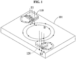
- FIG. 1 is a diagram illustrating a principle of transmitting an image through a metal body of a vehicle according to an example embodiment.
- a metal medium 101 may include, for example, a steel plate or a frame of a body of a vehicle.
- An example in which the metal medium 101 is a magnetic material and an example in which the metal medium 101 is a diamagnetic material will be described.
- Conductive layers of a first antenna 110 may form an electromagnetic field on a dielectric layer.
- an electromagnetic field in which a magnetic field is dominant may be formed on the metal medium 101 that is a propagation medium.
- An electric field E1 among generated electromagnetic fields may be propagated orthogonally to the metal medium 101 through an aperture of the first antenna 110.
- the propagated electric field E1 may form an electromagnetic field B in which a magnetic field is dominant in the metal medium 101.
- a second antenna 120 of a receiver may receive energy from an electromagnetic field formed in the metal medium 101.
- a change in the electromagnetic field B in which the magnetic field is dominant may be transferred in a dielectric layer to an electromagnetic field E2 in which an electric field is dominant, through an aperture of the second antenna 120.
- a magnetic field is dominant in the above metal material communication, impedance may slightly change despite a change in a shape and size of the metal medium 101. Also, since a permeability of the metal medium 101 is greater than that of air, an efficiency of propagation of a radio wave through the metal medium may be superior to that of a communication system in which radio waves propagate through the air.
- a steel may have a permeability of about 2,000 and a pure iron may have a permeability of about 4,000 to 5,000, which indicates that the permeability of the steel and the permeability of the pure iron are about 2,000 times and about 4,000 to 5,000 times greater than a permeability of air, respectively.
- a magnetic field may be much more strongly and farther propagated in a magnetic material in comparison to when the magnetic field is propagated in the air.
- a communication through the metal medium 101 that is, a magnetic material may allow an electromagnetic field to be farther propagated than a magnetic field communication through the air.
- a resonator and a circuit may need to be designed so that an electric field with a predetermined magnitude is formed in a metal body.
- a propagation efficiency of a metal medium with a high permeability may increase, and a electromagnetic field propagation distance may vary depending on a wavelength of an operating frequency. Due to the electromagnetic field formed on the metal medium 101, energy may be transferred to a resonator spaced apart by a predetermined distance from a metal medium. Since a magnetic field is dominant in the electromagnetic field formed on the metal medium 101, an electric field may be radiated from the metal medium 101. Accordingly, an antenna resonating at an operating frequency may receive energy when the antenna is within a predetermined distance from the metal medium 101.
- a dielectric of a dielectric layer of the first antenna 110 or the second antenna 120 may reduce a thickness and size of a resonator, and may form the electromagnetic field B in which the magnetic field is dominant on the metal medium 101, to transfer a sufficient amount of energy.
- an electromagnetic field E1 in which an electric field is dominant may be formed on the metal medium 101.
- the electromagnetic field B in which the magnetic field is dominant may not be formed on the metal medium 101 by the electric field that is radiated from an aperture.
- a permeability of each of a paramagnetic material and a diamagnetic material is similar to that of the air.
- an electromagnetic field may be propagated at a similar intensity to that of a propagation of a magnetic field in the air, not a higher intensity, similarly to a ferromagnetic material.
- distance in which a magnetic field is propagated in the air or a metal body may be similar.
- a pure iron that is a ferromagnetic material may have a permeability of 4,000 to 5,000 and aluminum that is a paramagnetic material or silver that is a diamagnetic material may have a permeability of about 1.0, and accordingly a magnetic field may be propagated in the metal body at different intensities.
- a signal may be propagated to the receiver by a current induced from a layer in contact with the metal medium 101 among conductive layers of the antenna to the metal medium 101.
- an electric field radiated from an aperture may be induced to the metal body, and accordingly a signal or power may be transmitted.
- FIG. 2 illustrates an antenna 210 and a transceiving circuit 220 according to an example embodiment.
- the antenna 210 includes a first layer that includes apertures and that is formed of a conductive material to face a metal medium, a second layer formed of a conductive material and located in an opposite side to the first layer, and a third layer formed of a dielectric material and located between the first layer and the second layer.
- FIG. 3 illustrates a plan view of an antenna 300 according to an example embodiment.
- the first layer and/or the second layer may include, but is not limited to, nine apertures 310 in a 3 ⁇ 3 array.
- a number of apertures may be determined based on an application and a communication environment.
- the first layer and the second layer may have a single aperture or a plurality of apertures, however, may not have an aperture depending on circumstances.
- an aperture may have a circular shape or polygonal shape, and have a size that is determined to transfer a sufficient amount of energy by forming an electromagnetic field in which a magnetic field is dominant on a metal medium.
- a thickness of each layer may be determined based on a wavelength and a skin depth so that an electromagnetic field in which a magnetic field is dominant may be formed on a metal medium to transfer a sufficient amount of energy.
- Other layers with different electric characteristics may be added to the first layer or the second layer in an opposite direction to the third layer.
- another dielectric layer may be added onto the first layer, to induce a formation of a strong electromagnetic field.
- a nonconductor may be added onto the first layer to prevent an electric connection to a metal medium.
- the third layer that is an intermediate layer between the first layer and the second layer may include a dielectric or a nonconductor.
- the third layer may include, but is not limited to, for example, at least one of a carbon fiber, acryl and polycarbonate.
- the third layer may include, for example, paint, paper or a polymer resin film.
- the third layer may include a plurality of layers with different characteristics, a plurality of dielectrics, or a nonconductor.
- An example of a configuration of an antenna with at least two dielectric layers is shown in FIG. 4.
- FIG. 4 illustrates a side view of an antenna according to an example embodiment.
- Dielectric layers 420 and 440 are located between conductive layers 410, 430 and 450, for example, copper.
- a number of dielectric layers or a thickness of each of the dielectric layers may be designed and changed based on an application or a communication environment, and detailed specifications may be determined to transfer enough energy to form an electromagnetic field in which a magnetic field is dominant on a
- a waveguide antenna Although an example of a waveguide antenna has been basically described above, other types of antennas may be used by designing a resonator with a structure to form an electromagnetic field in which a magnetic field is dominant in a metal body.
- a patch antenna, or a horn antenna may be used.
- a ferromagnetic material may be attached to the metal medium 101 in advance, to induce a strong magnetic field to the metal body.
- a dielectric or nonconductor may be attached onto the first layer, and a ferromagnetic material may be attached onto the dielectric or nonconductor.
- the first layer may be placed on the metal medium.
- the attached ferromagnetic material may form a strong magnetic field, and accordingly the magnetic field may be induced to the metal medium to form a stronger magnetic field in comparison to inducing of a magnetic field directly into the metal body.
- the attached ferromagnetic material is a refined steel or Mu-metal with a permeability of about 100,000 to 200,000, a much stronger magnetic field may be formed on the metal body.
- a method of winding a coil around a ferromagnetic material and attaching the ferromagnetic material to a metal body while generating a magnetic field in the ferromagnetic material may be used.
- the transceiving circuit 220 may be a circuit device configured to convert a signal transmitted and received from and to the antenna 210 that is a resonator into a meaningful signal.
- a circuit for transmission and a circuit for reception may be separately provided.
- the transceiving circuit may include a power supply circuit configured to operate a circuit or to supply a sufficient amount of power to a resonator, and a battery for the power system.
- a transmission circuit may have a similar structure to a structure of a transmission system of a general wireless communication, however, may additionally require a circuit configured to allow the resonator to radiate a sufficient amount of power. For example, a power amplifier (amp) or an automatic gain controller (AGC) may be required.
- a receiver may have a similar structure to a structure of a receiver of a general wireless communication system.
- a frequency used for a communication it is possible to select an optimum frequency based on characteristics of data to be transmitted, a communication environment, and the like.
- a relationship between frequencies and antenna sizes is shown in Table 1 below.
- a transmission and reception power was tested in a band of 27 megahertz (MHz) for an audio communication (radio set), instead of an image communication.
- the testing was performed in the following environment:
- a rated voltage of 13.8 V was measured using a tester through a radio circuit in the testing, and a distance between a transmission antenna and a reception antenna is about 1 meter (m).
- the measured currents changed based on an audio signal level, and a value of the measured currents is an average value.
- a transmission and reception of power may be performed as well as a data communication.
- a power may be transmitted similarly to a signal transmission, and accordingly a communication apparatus according to example embodiments may be a power transmitter or a power receiver.
- a power transmission circuit of the power transmitter may convert a direct current (DC) output from a power outlet into an analog signal or an RF signal, and may transmit a converted power through a power transmission resonator (hereinafter, is the same as an antenna in a signal transmission).
- a power reception circuit (hereinafter, is the same as an antenna in a signal reception) of the power receiver may receive an analog signal or RF signal radiated through a power transmission resonator of the power transmitter, using a power reception resonator of the power receiver, may convert the received the analog signal or RF signal to a DC, and may supply a power to a required circuit.
- an additionally required voltage may be converted by a DC-to-DC converter and supplied, if necessary.
- the power receiver includes a battery, the battery may be charged, or a power may be supplied to a required circuit while charging the battery.
- FIG. 5 is a block diagram illustrating a configuration of a system according to an example embodiment.
- a part 501 to transmit image data from a camera apparatus to an image processing apparatus and to supply a power depends on a wired connection.
- a part 501 for a data transmission and power supply may be implemented by a power transmission and a metal material communication using a metal body of a vehicle as a medium.
- a part 510 near a camera apparatus and a part 520 near an image processing apparatus may be added adjacent to the part 501 for a communication and power transmission to a general configuration of a rear black box (or a rear view camera) according to the related art.
- the part 510 may include an antenna 511 and a transceiving circuit 512
- the part 520 may include an antenna 521 and a transceiving circuit 522.
- Power supplied from a battery 530 of the vehicle (or a power source provided by the vehicle, for example, generated by the vehicle) may be transferred from the part 520 to the part 510 through a converter and a driver.
- a power transfer process is the same as those described above.
- the power may be transferred from the part 510 to a camera 540 through a converter and a battery 531.
- An image captured by the camera may be transferred to the part 510 again by passing through an image signal processor ISP via an encoder ENC 550 and a modem 560. Also, image data may be transferred from the part 510 to the part 520, as described above. A signal transferred to the part 520 may be provided on a display 541 through a modem 561 and a decoder DEC 551.
- FIGS. 6 and 7 illustrate examples of a vehicle 600 in which a camera apparatus is installed according to an example embodiment.
- a structure 610 with a camera may include a transceiving circuit, and may exchange signals and/or power using an electromagnetic field communication scheme via an antenna 620 installed in contact with a steel plate of a roof of the vehicle.
- an antenna 720 for a metal material communication may be attached at an arbitrary position of a vehicle 700, and may be attached near a structure 720 with a camera.
- the structure 710 and the antenna 720 may be implemented as a single device.
- FIGS. 6 and 7 illustrate examples in which a camera module and an antenna are attached outside the vehicle, however, there is no limitation thereto.
- the camera module and the antenna may be installed at an arbitrary position in the vehicle.
- the antenna may be installed in contact with an arbitrary metal medium of the vehicle, for example, a door or a pillar of the vehicle.
- the above camera apparatus may provide various benefits.
- a black box or a side view/rear view camera that is not included by default in a vehicle is installed in an aftermarket and is to operate, various difficulties in, for example, drilling the vehicle or inserting a line between interior materials, exist in the related art.
- a camera apparatus may not need to be connected via a wire separately from an image processing apparatus (that is generally installed near a driver's seat).
- a camera apparatus may also be useful in large vehicles, for example, buses, trailers or trucks.
- FIG. 8 illustrates a large vehicle in which a camera apparatus is installed according to an example embodiment.
- a large vehicle for example, a truck or bus, may be exposed to a risk of an accident caused by a failure to properly monitor a rear side or blind spot.
- a rear view camera and/or side view camera it is difficult to connect wiring from a camera part to a part near a driver's seat in the large vehicle.
- a communication may be performed without separate wiring to a driver's seat 830.
- a structure thereof is the same as described above, and a screen 910 of FIG. 9 may be provided to a driver.
Abstract
Description
- The following description relates to a communication apparatus and method, and more particularly, to an apparatus for transmitting and receiving an image signal from a side of a vehicle to another side.
- In a vehicle, various sensors or parts are connected to each other via wires. A rear view camera or a black box camera that monitors a rear side of the vehicle is also connected via a wire to supply power and transmit an image.
- However, due to the above wired connection, installation of rear view cameras or black box cameras for monitoring a rear view distributed in the aftermarket may be avoided. The wired connection may make it difficult to install a camera and may incur costs. Also, a vehicle may be damaged by, for example, drilling a steel plate of the vehicle. When a camera is removed from a vehicle because the camera is not used, a trace may remain.
- To replace the wired connection, a related art discloses an attempt to wirelessly transmit an image using a radio frequency (RF). In the following patent documents, some examples are shown.
- Korean Registration Patent Publication No.
10-1334391, published on November 29, 2013 -
U.S. Patent Publication No. 2011/0013020, published on January 20, 2011 , discloses a communication network that wirelessly transmits a vehicle rear view camera image. - According to an aspect of the present invention, there is provided a camera apparatus installed and used in a vehicle. The camera apparatus may include a camera module configured to generate an input image; a transceiving circuit configured to encode and modulate the input image and to provide a first signal; and an antenna attached to a metal body of the vehicle and configured to form an electromagnetic field on the metal body and to propagate the first signal received from the transceiving circuit by carrying the first signal in the electromagnetic field.
- The antenna may include a first layer formed of a conductive material and including at least one aperture facing the metal body; a second layer formed of a conductive material and located adjacent to the first layer; and a third layer formed of a dielectric material, located between the first layer and the second layer and configured to exchange electromagnetic waves with the metal body so that the first signal is carried in the electromagnetic field.
- The first layer may include nine apertures in a 3 × 3 array.
- The antenna may be further configured to receive power from an electromagnetic wave propagated through the metal body and to provide the power to the transceiving circuit, and the transceiving circuit may be further configured to supply power to the camera module through a converter.
- At least one of the first layer and the second layer may include a copper material. The third layer may include at least one of a carbon fiber, acryl and polycarbonate.
- According to another aspect of the present invention, there is provided an image processing apparatus that receives an image from a camera installed in a vehicle. The image processing apparatus may include an antenna attached at a first position of a metal body of the vehicle and configured to receive a first signal corresponding to the image when a camera-side antenna attached at a second position of the metal body forms an electromagnetic field and propagates the first signal by carrying the first signal in the electromagnetic field; and a transceiving circuit configured to modulate and decode the first signal and to provide the first signal as the image.
- The antenna may include a first layer formed of a conductive material and including at least one aperture facing the metal body; a second layer formed of a conductive material and located adjacent to the first layer; and a third layer formed of a dielectric material, located between the first layer and the second layer, and configured to receive the first signal by exchanging electromagnetic waves with the metal body.
- At least one of the first layer and the second layer may include a copper material. The third layer may include at least one of a carbon fiber, acryl and polycarbonate.
- When a voltage supplied from a battery of the vehicle and/or a power source of the vehicle is converted and transferred, the transceiving circuit may be further configured to transfer power to the antenna and the antenna may be further configured to form an electromagnetic field on the metal body and propagate the power to the camera-side antenna.
-
-
FIG. 1 is a diagram illustrating a principle of transmitting an image through a metal body of a vehicle according to an example embodiment. -
FIG. 2 is a diagram illustrating an antenna and a transceiving circuit according to an example embodiment. -
FIG. 3 is a plan view of an antenna according to an example embodiment. -
FIG. 4 is a side view of an antenna according to an example embodiment. -
FIG. 5 is a block diagram illustrating a configuration of a system according to an example embodiment. -
FIG. 6 is a diagram illustrating a vehicle in which a camera apparatus is installed according to an example embodiment. -
FIG. 7 is a side view of a vehicle in which a camera apparatus is installed according to an example embodiment. -
FIG. 8 is a diagram illustrating a large vehicle in which a camera apparatus is installed according to an example embodiment. -
FIG. 9 is a diagram illustrating a display of a transmitted image according to an example embodiment. - Hereinafter, example embodiments will be described in detail with reference to the accompanying drawings. The scope of the right, however, should not be construed as limited to the example embodiments set forth herein. In the following description, like drawing reference numerals are used for like elements, even in different drawings.
- All terms used herein are selected from general terms being used in the related arts. Yet, the meanings of the terms used herein may be changed depending on a change and/or development of technologies, a custom, or preference of an operator in the art. Accordingly, the terms are merely examples to describe the example embodiments, and should not be construed as limited to the technical idea of the present disclosure.
- Also, in a specific case, most appropriate terms are arbitrarily selected by the applicant for ease of description and/or for ease of understanding. In this instance, the meanings of the arbitrarily used terms will be clearly explained in the corresponding description. Hence, the terms should be understood not by the simple names of the terms but by the meanings of the terms and the following overall description of this specification.
- A communication system according to example embodiments includes a camera apparatus for transmitting an image, and an image processing apparatus for receiving an image and processing the image. According to a related art, a process of transmitting image data from a camera apparatus to an image processing apparatus is performed by, for example, a wired communication or a radio frequency (RF)-based wireless communication. However, according to example embodiments, image data may be transmitted from the camera apparatus to the image processing apparatus by a metal material communication (or a magnetic field communication) that employs a body of a vehicle as a medium for a communication. Also, the image processing apparatus may transmit a power supplied to the vehicle to the camera apparatus, to transfer an operating power of the camera apparatus.
- According to an example embodiment, a camera apparatus may be a rear view camera of a black box for multi-channel vehicles. However, this is merely an example, and different types of products may be used. For example, one of a front view camera, a rear view camera, a left side view camera and a right side view camera that form an omniview or omnivision camera system that is recently provided as an optional item by automakers. As described above, the camera apparatus may transmit an image using an electromagnetic field induction scheme in a metal body of a vehicle instead of transmitting an image using a separate wire similarly to the related art.
- The camera apparatus may include a camera module configured to generate an input image, and a transceiving circuit configured to encode and modulate the input image and to provide a first signal (hereinafter, refers to an electrical signal and/or magnetic signal). Also, the camera apparatus may include an antenna that is attached to the metal body of the vehicle and that is configured to form an electromagnetic field on the metal body and to propagate the first signal received from the transceiving circuit by carrying the first signal in the electromagnetic field. A configuration of the antenna will be further described with reference to
FIGS. 3 and4 . - According to an example embodiment, an image processing apparatus may receive an image from the camera apparatus through the metal body using a metal material communication, and may process the image. The image processing apparatus may include an antenna attached at a first position of the metal body. When a camera apparatus-side antenna attached at a second position of the metal body forms an electromagnetic field on the metal body and propagates a first signal corresponding to the image by carrying the first signal in the electromagnetic field, the antenna at the first position may receive the first signal. The image processing apparatus may also include a transceiving circuit configured to modulate and decode the first signal and provide the first signal as the image.
- A principle of transmitting an image through a metal body of a vehicle is described with reference to
FIG. 1. FIG. 1 is a diagram illustrating a principle of transmitting an image through a metal body of a vehicle according to an example embodiment. Ametal medium 101 may include, for example, a steel plate or a frame of a body of a vehicle. An example in which themetal medium 101 is a magnetic material and an example in which themetal medium 101 is a diamagnetic material will be described. - Conductive layers of a
first antenna 110 may form an electromagnetic field on a dielectric layer. By the electromagnetic field, an electromagnetic field in which a magnetic field is dominant may be formed on themetal medium 101 that is a propagation medium. An electric field E1 among generated electromagnetic fields may be propagated orthogonally to themetal medium 101 through an aperture of thefirst antenna 110. The propagated electric field E1 may form an electromagnetic field B in which a magnetic field is dominant in themetal medium 101. - Based on a similar structure and principle by a reversibility theory, a
second antenna 120 of a receiver may receive energy from an electromagnetic field formed in themetal medium 101. In the above process, a change in the electromagnetic field B in which the magnetic field is dominant may be transferred in a dielectric layer to an electromagnetic field E2 in which an electric field is dominant, through an aperture of thesecond antenna 120. - Since a magnetic field is dominant in the above metal material communication, impedance may slightly change despite a change in a shape and size of the
metal medium 101. Also, since a permeability of themetal medium 101 is greater than that of air, an efficiency of propagation of a radio wave through the metal medium may be superior to that of a communication system in which radio waves propagate through the air. - For example, a steel may have a permeability of about 2,000 and a pure iron may have a permeability of about 4,000 to 5,000, which indicates that the permeability of the steel and the permeability of the pure iron are about 2,000 times and about 4,000 to 5,000 times greater than a permeability of air, respectively. In other words, a magnetic field may be much more strongly and farther propagated in a magnetic material in comparison to when the magnetic field is propagated in the air. Accordingly, a communication through the
metal medium 101, that is, a magnetic material may allow an electromagnetic field to be farther propagated than a magnetic field communication through the air. To form an electromagnetic field in which a magnetic field is dominant, a resonator and a circuit may need to be designed so that an electric field with a predetermined magnitude is formed in a metal body. - For example, a propagation efficiency of a metal medium with a high permeability may increase, and a electromagnetic field propagation distance may vary depending on a wavelength of an operating frequency. Due to the electromagnetic field formed on the
metal medium 101, energy may be transferred to a resonator spaced apart by a predetermined distance from a metal medium. Since a magnetic field is dominant in the electromagnetic field formed on themetal medium 101, an electric field may be radiated from themetal medium 101. Accordingly, an antenna resonating at an operating frequency may receive energy when the antenna is within a predetermined distance from themetal medium 101. - A dielectric of a dielectric layer of the
first antenna 110 or thesecond antenna 120 may reduce a thickness and size of a resonator, and may form the electromagnetic field B in which the magnetic field is dominant on themetal medium 101, to transfer a sufficient amount of energy. - For example, by a current supplied to a conductive layer, an electromagnetic field E1 in which an electric field is dominant may be formed on the
metal medium 101. In this example, the electromagnetic field B in which the magnetic field is dominant may not be formed on themetal medium 101 by the electric field that is radiated from an aperture. This is because a permeability of each of a paramagnetic material and a diamagnetic material is similar to that of the air. Accordingly, in themetal medium 101 that is a paramagnetic material or a diamagnetic material, an electromagnetic field may be propagated at a similar intensity to that of a propagation of a magnetic field in the air, not a higher intensity, similarly to a ferromagnetic material. In other words, distance in which a magnetic field is propagated in the air or a metal body may be similar. - A pure iron that is a ferromagnetic material may have a permeability of 4,000 to 5,000 and aluminum that is a paramagnetic material or silver that is a diamagnetic material may have a permeability of about 1.0, and accordingly a magnetic field may be propagated in the metal body at different intensities. In this example, a signal may be propagated to the receiver by a current induced from a layer in contact with the
metal medium 101 among conductive layers of the antenna to themetal medium 101. Also, an electric field radiated from an aperture may be induced to the metal body, and accordingly a signal or power may be transmitted. -
FIG. 2 illustrates anantenna 210 and atransceiving circuit 220 according to an example embodiment. Theantenna 210 includes a first layer that includes apertures and that is formed of a conductive material to face a metal medium, a second layer formed of a conductive material and located in an opposite side to the first layer, and a third layer formed of a dielectric material and located between the first layer and the second layer. - A structure of an antenna is also described with reference to
FIG. 3. FIG. 3 illustrates a plan view of anantenna 300 according to an example embodiment. For example, the first layer and/or the second layer may include, but is not limited to, nineapertures 310 in a 3 × 3 array. However, a number of apertures may be determined based on an application and a communication environment. Thus, the first layer and the second layer may have a single aperture or a plurality of apertures, however, may not have an aperture depending on circumstances. For example, an aperture may have a circular shape or polygonal shape, and have a size that is determined to transfer a sufficient amount of energy by forming an electromagnetic field in which a magnetic field is dominant on a metal medium. - A thickness of each layer may be determined based on a wavelength and a skin depth so that an electromagnetic field in which a magnetic field is dominant may be formed on a metal medium to transfer a sufficient amount of energy. Other layers with different electric characteristics may be added to the first layer or the second layer in an opposite direction to the third layer. In an example, another dielectric layer may be added onto the first layer, to induce a formation of a strong electromagnetic field. In another example, a nonconductor may be added onto the first layer to prevent an electric connection to a metal medium.
- The third layer that is an intermediate layer between the first layer and the second layer may include a dielectric or a nonconductor. The third layer may include, but is not limited to, for example, at least one of a carbon fiber, acryl and polycarbonate. Also, the third layer may include, for example, paint, paper or a polymer resin film. In addition, the third layer may include a plurality of layers with different characteristics, a plurality of dielectrics, or a nonconductor. An example of a configuration of an antenna with at least two dielectric layers is shown in
FIG. 4. FIG. 4 illustrates a side view of an antenna according to an example embodiment.Dielectric layers conductive layers - Although an example of a waveguide antenna has been basically described above, other types of antennas may be used by designing a resonator with a structure to form an electromagnetic field in which a magnetic field is dominant in a metal body. For example, a patch antenna, or a horn antenna may be used.
- A ferromagnetic material may be attached to the
metal medium 101 in advance, to induce a strong magnetic field to the metal body. For example, a dielectric or nonconductor may be attached onto the first layer, and a ferromagnetic material may be attached onto the dielectric or nonconductor. The first layer may be placed on the metal medium. - The attached ferromagnetic material may form a strong magnetic field, and accordingly the magnetic field may be induced to the metal medium to form a stronger magnetic field in comparison to inducing of a magnetic field directly into the metal body. For example, when the attached ferromagnetic material is a refined steel or Mu-metal with a permeability of about 100,000 to 200,000, a much stronger magnetic field may be formed on the metal body. Also, a method of winding a coil around a ferromagnetic material and attaching the ferromagnetic material to a metal body while generating a magnetic field in the ferromagnetic material may be used.
- Referring back to
FIG. 2 , thetransceiving circuit 220 may be a circuit device configured to convert a signal transmitted and received from and to theantenna 210 that is a resonator into a meaningful signal. A circuit for transmission and a circuit for reception may be separately provided. The transceiving circuit may include a power supply circuit configured to operate a circuit or to supply a sufficient amount of power to a resonator, and a battery for the power system. A transmission circuit may have a similar structure to a structure of a transmission system of a general wireless communication, however, may additionally require a circuit configured to allow the resonator to radiate a sufficient amount of power. For example, a power amplifier (amp) or an automatic gain controller (AGC) may be required. A receiver may have a similar structure to a structure of a receiver of a general wireless communication system. - Although there is no particular limitation to a frequency used for a communication, it is possible to select an optimum frequency based on characteristics of data to be transmitted, a communication environment, and the like. A relationship between frequencies and antenna sizes (for example, a length of a side of the
antenna 300 ofFIG. 3 ) is shown in Table 1 below.[Table 1] 150 mm 100 mm 60 mm Frequency f (Hz) 25000000 25000000 25000000 Light velocity C (m/s) 300000000 300000000 300000000 Wavelength λ (m) 12 12 12 Wavelength in waveguide λg (m) 7.236 7.500 7.500 Aperture (λgmm) 4.146 2.667 1.600 Side gap (λgmm) 1.382 0.933 0.800 termediate gap (λgmn) 2.764 1.733 0.800 Copper T (λgmm) 0.041 0.040 0.040 Dielectric T (λgmm) 0.138 0.133 0.267 - A transmission and reception power was tested in a band of 27 megahertz (MHz) for an audio communication (radio set), instead of an image communication. The testing was performed in the following environment:
- Standby power: 1.794 W (regardless of an antenna size)
- Transmission power
- Antenna size 150 mm × 150 mm: 22.08 W
- Antenna size 100 mm × 100 mm: 21.39 W
- Antenna size 60 mm × 60 mm: 10.35 W
- Reception power
- Antenna size 150 mm × 150 mm: 2.76 W
- Antenna size 100 mm × 100 mm: 3.45 W
- Antenna size 60 mm × 60 mm: 6.21 W
- A rated voltage of 13.8 V was measured using a tester through a radio circuit in the testing, and a distance between a transmission antenna and a reception antenna is about 1 meter (m).
- Currents measured in the testing are shown as below.
[Table 2] Antenna Size State Tx Rx 60 mm × 60 mm Standby 0.13 (A) 0.13 (A) Acting 0.75 (A) 0.45 (A) 100 mm × 100 mm Standby 0.13 (A) 0.13 (A) Acting 1.55 (A) 0.25 (A) 150 mm × 150 mm Standby 0.13 (A) 0.13 (A) Acting 1.60 (A) 0.20 (A) - The measured currents changed based on an audio signal level, and a value of the measured currents is an average value.
- According to an example embodiment, a transmission and reception of power may be performed as well as a data communication. A power may be transmitted similarly to a signal transmission, and accordingly a communication apparatus according to example embodiments may be a power transmitter or a power receiver. A power transmission circuit of the power transmitter may convert a direct current (DC) output from a power outlet into an analog signal or an RF signal, and may transmit a converted power through a power transmission resonator (hereinafter, is the same as an antenna in a signal transmission).
- A power reception circuit (hereinafter, is the same as an antenna in a signal reception) of the power receiver may receive an analog signal or RF signal radiated through a power transmission resonator of the power transmitter, using a power reception resonator of the power receiver, may convert the received the analog signal or RF signal to a DC, and may supply a power to a required circuit. In an example, an additionally required voltage may be converted by a DC-to-DC converter and supplied, if necessary. In another example, when the power receiver includes a battery, the battery may be charged, or a power may be supplied to a required circuit while charging the battery.
-
FIG. 5 is a block diagram illustrating a configuration of a system according to an example embodiment. In a related art, apart 501 to transmit image data from a camera apparatus to an image processing apparatus and to supply a power depends on a wired connection. As described above, recently, attempts to transmit image data via an RF-based wireless communication are being made, however, a battery needs to be charged or a separate power outlet needs to be connected due to a difficulty in power supply. According to an example embodiment, apart 501 for a data transmission and power supply may be implemented by a power transmission and a metal material communication using a metal body of a vehicle as a medium. - In the block diagram, a
part 510 near a camera apparatus and apart 520 near an image processing apparatus may be added adjacent to thepart 501 for a communication and power transmission to a general configuration of a rear black box (or a rear view camera) according to the related art. - The
part 510 may include anantenna 511 and atransceiving circuit 512, and thepart 520 may include anantenna 521 and atransceiving circuit 522. Power supplied from abattery 530 of the vehicle (or a power source provided by the vehicle, for example, generated by the vehicle) may be transferred from thepart 520 to thepart 510 through a converter and a driver. A power transfer process is the same as those described above. The power may be transferred from thepart 510 to acamera 540 through a converter and abattery 531. - An image captured by the camera may be transferred to the
part 510 again by passing through an image signal processor ISP via anencoder ENC 550 and amodem 560. Also, image data may be transferred from thepart 510 to thepart 520, as described above. A signal transferred to thepart 520 may be provided on adisplay 541 through amodem 561 and adecoder DEC 551. -
FIGS. 6 and7 illustrate examples of avehicle 600 in which a camera apparatus is installed according to an example embodiment. Astructure 610 with a camera may include a transceiving circuit, and may exchange signals and/or power using an electromagnetic field communication scheme via anantenna 620 installed in contact with a steel plate of a roof of the vehicle. As shown inFIG. 7 , anantenna 720 for a metal material communication may be attached at an arbitrary position of avehicle 700, and may be attached near astructure 720 with a camera. Although not shown in the drawings, thestructure 710 and theantenna 720 may be implemented as a single device. -
FIGS. 6 and7 illustrate examples in which a camera module and an antenna are attached outside the vehicle, however, there is no limitation thereto. For example, the camera module and the antenna may be installed at an arbitrary position in the vehicle. In this example, the antenna may be installed in contact with an arbitrary metal medium of the vehicle, for example, a door or a pillar of the vehicle. As described above, the above camera apparatus may provide various benefits. When a black box or a side view/rear view camera that is not included by default in a vehicle is installed in an aftermarket and is to operate, various difficulties in, for example, drilling the vehicle or inserting a line between interior materials, exist in the related art. However, according to example embodiments, a camera apparatus may not need to be connected via a wire separately from an image processing apparatus (that is generally installed near a driver's seat). - Although a transmission of image data has been described merely as an example, various types of sensors that are installed in a vehicle recently, for example, an ultrasonic sensor, a light intensity sensor, a rain sensor, light detection and ranging (LiDAR) or LADAR, may transfer measured values to a controller of the vehicle using the same scheme. Thus, according to example embodiments and modifications thereof, it is possible to greatly reduce wiring in a vehicle. Therefore, it is possible to expect additional gains, for example, a reduction in manufacturing costs of vehicles, an increase in a fuel efficiency due to a weight reduction, and the like.
- A camera apparatus according to an example embodiment may also be useful in large vehicles, for example, buses, trailers or trucks.
FIG. 8 illustrates a large vehicle in which a camera apparatus is installed according to an example embodiment. A large vehicle, for example, a truck or bus, may be exposed to a risk of an accident caused by a failure to properly monitor a rear side or blind spot. Despite many attempts to install a rear view camera and/or side view camera in a large vehicle, it is difficult to connect wiring from a camera part to a part near a driver's seat in the large vehicle. - When a
camera apparatus 810 for a magnetic field communication using ametal body 820 of the large vehicle as a communication medium is installed as described above, a communication may be performed without separate wiring to a driver'sseat 830. A structure thereof is the same as described above, and ascreen 910 ofFIG. 9 may be provided to a driver. - While a few example embodiments have been shown and described with reference to the accompanying drawings, it will be apparent to those skilled in the art that various modifications and variations can be made from the foregoing descriptions. For example, adequate effects may be achieved even if the foregoing processes and methods are carried out in different order than described above, and/or the aforementioned elements, such as systems, structures, devices, or circuits are combined or coupled in different forms and modes than as described above or be substituted or switched with other components or equivalents. Thus, other implementations, alternative embodiments and equivalents to the claimed subject matter are construed as being within the appended claims.
Claims (11)
- A camera apparatus installed and used in a vehicle, the camera apparatus comprising:a camera module configured to generate an input image;a transceiving circuit configured to encode and modulate the input image and to provide a first signal; andan antenna attached to a metal body of the vehicle and configured to form an electromagnetic field on the metal body and to propagate the first signal received from the transceiving circuit by carrying the first signal in the electromagnetic field.
- The camera apparatus of claim 1, wherein the antenna comprises:a first layer formed of a conductive material and comprising at least one aperture facing the metal body;a second layer formed of a conductive material and located adjacent to the first layer; anda third layer formed of a dielectric material, located between the first layer and the second layer and configured to exchange electromagnetic waves with the metal body so that the first signal is carried in the electromagnetic field.
- The camera apparatus of claim 2, wherein the first layer includes nine apertures in a 3 × 3 array.
- The camera apparatus of claim 1, wherein the antenna is further configured to receive power from an electromagnetic wave propagated through the metal body and to provide the power to the transceiving circuit, and the transceiving circuit is further configured to supply power to the camera module through a converter.
- The camera apparatus of claim 1, wherein at least one of the first layer and the second layer comprises a copper material.
- The camera apparatus of claim 1, wherein the third layer comprises at least one of a carbon fiber, acryl and polycarbonate.
- An image processing apparatus that receives an image from a camera installed in a vehicle, the image processing apparatus comprising:an antenna attached at a first position of a metal body of the vehicle and configured to receive a first signal corresponding to the image when a camera-side antenna attached at a second position of the metal body forms an electromagnetic field and propagates the first signal by carrying the first signal in the electromagnetic field; anda transceiving circuit configured to modulate and decode the first signal and to provide the first signal as the image.
- The image processing apparatus of claim 7, wherein the antenna comprises:a first layer formed of a conductive material and comprising at least one aperture facing the metal body;a second layer formed of a conductive material and located adjacent to the first layer; anda third layer formed of a dielectric material, located between the first layer and the second layer, and configured to receive the first signal by exchanging electromagnetic waves with the metal body.
- The image processing apparatus of claim 8, wherein at least one of the first layer and the second layer comprises a copper material.
- The image processing apparatus of claim 8, wherein the third layer comprises at least one of a carbon fiber, acryl and polycarbonate.
- The image processing apparatus of claim 7, wherein when a voltage supplied from a battery of the vehicle or a power source of the vehicle is converted and transferred, the transceiving circuit is further configured to transfer power to the antenna and the antenna is further configured to form an electromagnetic field on the metal body and propagate the power to the camera-side antenna.
Applications Claiming Priority (1)
| Application Number | Priority Date | Filing Date | Title |
|---|---|---|---|
| PCT/KR2016/014523 WO2018110717A1 (en) | 2016-12-12 | 2016-12-12 | In-vehicle communication device and method |
Publications (3)
| Publication Number | Publication Date |
|---|---|
| EP3554061A1 true EP3554061A1 (en) | 2019-10-16 |
| EP3554061A4 EP3554061A4 (en) | 2020-07-22 |
| EP3554061B1 EP3554061B1 (en) | 2022-01-12 |
Family
ID=62558887
Family Applications (1)
| Application Number | Title | Priority Date | Filing Date |
|---|---|---|---|
| EP16923997.7A Active EP3554061B1 (en) | 2016-12-12 | 2016-12-12 | In-vehicle communication device and method |
Country Status (5)
| Country | Link |
|---|---|
| US (1) | US10622727B2 (en) |
| EP (1) | EP3554061B1 (en) |
| JP (1) | JP6829852B2 (en) |
| CN (1) | CN108702429B (en) |
| WO (1) | WO2018110717A1 (en) |
Families Citing this family (4)
| Publication number | Priority date | Publication date | Assignee | Title |
|---|---|---|---|---|
| US10442400B2 (en) | 2016-11-01 | 2019-10-15 | GM Global Technology Operations LLC | Wiper assembly and method |
| US10363889B2 (en) * | 2017-07-07 | 2019-07-30 | GM Global Technology Operations LLC | Vehicle wireless electrical connection system and method |
| KR102228163B1 (en) * | 2017-07-17 | 2021-03-17 | 주식회사 지엔테크놀로지스 | Apparatus and method for tranmitting and receiving signal in vessel |
| KR102209371B1 (en) * | 2018-11-29 | 2021-02-01 | 주식회사 지엔테크놀로지스 | Electromagnetic coupling apparatus for energy saving and wireless communication system comprising the electromagnetic coupling apparatus |
Family Cites Families (15)
| Publication number | Priority date | Publication date | Assignee | Title |
|---|---|---|---|---|
| JPH03220802A (en) * | 1990-01-26 | 1991-09-30 | Pioneer Electron Corp | Microstrip antenna |
| US8169311B1 (en) * | 1999-12-15 | 2012-05-01 | Automotive Technologies International, Inc. | Wireless transmission system for vehicular component control and monitoring |
| JP2005294920A (en) * | 2004-03-31 | 2005-10-20 | Auto Network Gijutsu Kenkyusho:Kk | Image pickup device and image pickup system employing image pickup device |
| WO2008024993A2 (en) * | 2006-08-25 | 2008-02-28 | Rayspan Corporation | Antennas based on metamaterial structures |
| US20090244282A1 (en) * | 2008-04-01 | 2009-10-01 | Francisco Jose Eguiguren | Vehicle camera system |
| KR100880115B1 (en) | 2008-04-21 | 2009-01-23 | 주식회사 에지텍 | Wireless transceiver system of rear and side view for vehicle with no wire connection to vehicle and method thereof |
| KR101124435B1 (en) * | 2009-11-02 | 2012-03-21 | 포항공과대학교 산학협력단 | Transmission lines and antennas for automobile |
| KR101134305B1 (en) * | 2010-04-12 | 2012-04-09 | (주)헤스코 | Car camera built in shark antenna |
| JP2013179440A (en) * | 2012-02-28 | 2013-09-09 | Mitsubishi Electric Corp | Array antenna device |
| KR101398991B1 (en) * | 2012-08-31 | 2014-05-28 | 숭실대학교산학협력단 | Wireless power receiver and wireless power transfer, wireless power tranceiver system and wireless power tranceiver mobile device |
| KR101334391B1 (en) | 2013-01-25 | 2013-11-29 | (주)월드뷰 | Multi channel blackbox with wireless communications |
| US10468914B2 (en) * | 2013-03-11 | 2019-11-05 | Robert Bosch Gmbh | Contactless power transfer system |
| US10038237B2 (en) * | 2015-11-11 | 2018-07-31 | Raytheon Company | Modified cavity-backed microstrip patch antenna |
| KR101709077B1 (en) * | 2015-11-20 | 2017-02-22 | 현대자동차주식회사 | Antenna apparatus, manufacture method of antenna apparatus, vehicle having the same |
| CN205490871U (en) * | 2016-03-31 | 2016-08-17 | 贵州詹阳动力重工有限公司 | Remote wireless image transmission system of wireless remote control obstacles removing car |
-
2016
- 2016-12-12 EP EP16923997.7A patent/EP3554061B1/en active Active
- 2016-12-12 JP JP2019552431A patent/JP6829852B2/en active Active
- 2016-12-12 US US15/552,834 patent/US10622727B2/en active Active
- 2016-12-12 WO PCT/KR2016/014523 patent/WO2018110717A1/en active Application Filing
- 2016-12-12 CN CN201680011814.2A patent/CN108702429B/en active Active
Also Published As
| Publication number | Publication date |
|---|---|
| US10622727B2 (en) | 2020-04-14 |
| WO2018110717A1 (en) | 2018-06-21 |
| EP3554061A4 (en) | 2020-07-22 |
| CN108702429A (en) | 2018-10-23 |
| CN108702429B (en) | 2021-09-07 |
| JP2020502959A (en) | 2020-01-23 |
| US20180241134A1 (en) | 2018-08-23 |
| EP3554061B1 (en) | 2022-01-12 |
| JP6829852B2 (en) | 2021-02-17 |
Similar Documents
| Publication | Publication Date | Title |
|---|---|---|
| EP3554061B1 (en) | In-vehicle communication device and method | |
| CN104183900B (en) | Vehicle antenna | |
| KR0156300B1 (en) | Loop antenna of all directions | |
| US6232926B1 (en) | Dual coupled vehicle glass mount antenna system | |
| KR101784706B1 (en) | 8-Band Shark Fin Antenna for Vehicle | |
| EP3086476B1 (en) | Antenna system | |
| EP1088365A1 (en) | Multiband vehicle antenna | |
| CN113690570A (en) | Antenna device, electronic apparatus, and method for designing antenna device | |
| EP3223361B1 (en) | Back door and glass antenna | |
| US6292149B1 (en) | All-around vehicle antenna apparatus | |
| JP2001345620A (en) | Mobile telephone antenna device | |
| JP2014123999A (en) | Non-contact power receiving device | |
| US11362422B2 (en) | Device and method for intra-ship communication | |
| US7286086B2 (en) | Gain-adjustable antenna | |
| US20140191911A1 (en) | Antenna Assembly | |
| US7106263B2 (en) | Window-integrated antenna for LMS and diversitary FM reception in mobile motor vehicles | |
| KR102264433B1 (en) | Apparatus and method for tranmitting and receiving signal in vehicle | |
| KR102128983B1 (en) | Side mirror antenna device for vehicle | |
| JP2003332840A (en) | Antenna device and radio equipment the same | |
| US20070109112A1 (en) | Machine body antenna | |
| JP2001094328A (en) | Manhole cover antenna and data collection system | |
| CN110537290B (en) | Converter device and motor vehicle having a converter device | |
| JP2004345364A (en) | Tire monitoring system | |
| JP2002353721A (en) | Vehicle use antenna system | |
| KR101627513B1 (en) | The apparatus of smart radar detector with patch array antenna and coupler |
Legal Events
| Date | Code | Title | Description |
|---|---|---|---|
| STAA | Information on the status of an ep patent application or granted ep patent |
Free format text: STATUS: THE INTERNATIONAL PUBLICATION HAS BEEN MADE |
|
| PUAI | Public reference made under article 153(3) epc to a published international application that has entered the european phase |
Free format text: ORIGINAL CODE: 0009012 |
|
| STAA | Information on the status of an ep patent application or granted ep patent |
Free format text: STATUS: REQUEST FOR EXAMINATION WAS MADE |
|
| 17P | Request for examination filed |
Effective date: 20190708 |
|
| AK | Designated contracting states |
Kind code of ref document: A1 Designated state(s): AL AT BE BG CH CY CZ DE DK EE ES FI FR GB GR HR HU IE IS IT LI LT LU LV MC MK MT NL NO PL PT RO RS SE SI SK SM TR |
|
| AX | Request for extension of the european patent |
Extension state: BA ME |
|
| DAV | Request for validation of the european patent (deleted) | ||
| DAX | Request for extension of the european patent (deleted) | ||
| A4 | Supplementary search report drawn up and despatched |
Effective date: 20200622 |
|
| RIC1 | Information provided on ipc code assigned before grant |
Ipc: B60R 1/00 20060101ALI20200616BHEP Ipc: H04N 5/232 20060101ALI20200616BHEP Ipc: H01Q 1/32 20060101ALI20200616BHEP Ipc: H04N 5/225 20060101AFI20200616BHEP Ipc: H01Q 1/38 20060101ALI20200616BHEP Ipc: H04B 5/00 20060101ALI20200616BHEP Ipc: H04B 7/06 20060101ALI20200616BHEP Ipc: H01Q 1/24 20060101ALI20200616BHEP |
|
| GRAP | Despatch of communication of intention to grant a patent |
Free format text: ORIGINAL CODE: EPIDOSNIGR1 |
|
| STAA | Information on the status of an ep patent application or granted ep patent |
Free format text: STATUS: GRANT OF PATENT IS INTENDED |
|
| INTG | Intention to grant announced |
Effective date: 20210831 |
|
| GRAS | Grant fee paid |
Free format text: ORIGINAL CODE: EPIDOSNIGR3 |
|
| GRAA | (expected) grant |
Free format text: ORIGINAL CODE: 0009210 |
|
| STAA | Information on the status of an ep patent application or granted ep patent |
Free format text: STATUS: THE PATENT HAS BEEN GRANTED |
|
| AK | Designated contracting states |
Kind code of ref document: B1 Designated state(s): AL AT BE BG CH CY CZ DE DK EE ES FI FR GB GR HR HU IE IS IT LI LT LU LV MC MK MT NL NO PL PT RO RS SE SI SK SM TR |
|
| REG | Reference to a national code |
Ref country code: GB Ref legal event code: FG4D |
|
| REG | Reference to a national code |
Ref country code: CH Ref legal event code: EP |
|
| REG | Reference to a national code |
Ref country code: FI Ref legal event code: FGE |
|
| REG | Reference to a national code |
Ref country code: DE Ref legal event code: R096 Ref document number: 602016068414 Country of ref document: DE |
|
| REG | Reference to a national code |
Ref country code: IE Ref legal event code: FG4D |
|
| REG | Reference to a national code |
Ref country code: AT Ref legal event code: REF Ref document number: 1463143 Country of ref document: AT Kind code of ref document: T Effective date: 20220215 |
|
| REG | Reference to a national code |
Ref country code: SE Ref legal event code: TRGR |
|
| REG | Reference to a national code |
Ref country code: LT Ref legal event code: MG9D |
|
| REG | Reference to a national code |
Ref country code: NL Ref legal event code: MP Effective date: 20220112 |
|
| REG | Reference to a national code |
Ref country code: AT Ref legal event code: MK05 Ref document number: 1463143 Country of ref document: AT Kind code of ref document: T Effective date: 20220112 |
|
| PG25 | Lapsed in a contracting state [announced via postgrant information from national office to epo] |
Ref country code: NL Free format text: LAPSE BECAUSE OF FAILURE TO SUBMIT A TRANSLATION OF THE DESCRIPTION OR TO PAY THE FEE WITHIN THE PRESCRIBED TIME-LIMIT Effective date: 20220112 |
|
| PG25 | Lapsed in a contracting state [announced via postgrant information from national office to epo] |
Ref country code: RS Free format text: LAPSE BECAUSE OF FAILURE TO SUBMIT A TRANSLATION OF THE DESCRIPTION OR TO PAY THE FEE WITHIN THE PRESCRIBED TIME-LIMIT Effective date: 20220112 Ref country code: PT Free format text: LAPSE BECAUSE OF FAILURE TO SUBMIT A TRANSLATION OF THE DESCRIPTION OR TO PAY THE FEE WITHIN THE PRESCRIBED TIME-LIMIT Effective date: 20220512 Ref country code: NO Free format text: LAPSE BECAUSE OF FAILURE TO SUBMIT A TRANSLATION OF THE DESCRIPTION OR TO PAY THE FEE WITHIN THE PRESCRIBED TIME-LIMIT Effective date: 20220412 Ref country code: LT Free format text: LAPSE BECAUSE OF FAILURE TO SUBMIT A TRANSLATION OF THE DESCRIPTION OR TO PAY THE FEE WITHIN THE PRESCRIBED TIME-LIMIT Effective date: 20220112 Ref country code: HR Free format text: LAPSE BECAUSE OF FAILURE TO SUBMIT A TRANSLATION OF THE DESCRIPTION OR TO PAY THE FEE WITHIN THE PRESCRIBED TIME-LIMIT Effective date: 20220112 Ref country code: ES Free format text: LAPSE BECAUSE OF FAILURE TO SUBMIT A TRANSLATION OF THE DESCRIPTION OR TO PAY THE FEE WITHIN THE PRESCRIBED TIME-LIMIT Effective date: 20220112 Ref country code: BG Free format text: LAPSE BECAUSE OF FAILURE TO SUBMIT A TRANSLATION OF THE DESCRIPTION OR TO PAY THE FEE WITHIN THE PRESCRIBED TIME-LIMIT Effective date: 20220412 |
|
| PG25 | Lapsed in a contracting state [announced via postgrant information from national office to epo] |
Ref country code: PL Free format text: LAPSE BECAUSE OF FAILURE TO SUBMIT A TRANSLATION OF THE DESCRIPTION OR TO PAY THE FEE WITHIN THE PRESCRIBED TIME-LIMIT Effective date: 20220112 Ref country code: LV Free format text: LAPSE BECAUSE OF FAILURE TO SUBMIT A TRANSLATION OF THE DESCRIPTION OR TO PAY THE FEE WITHIN THE PRESCRIBED TIME-LIMIT Effective date: 20220112 Ref country code: GR Free format text: LAPSE BECAUSE OF FAILURE TO SUBMIT A TRANSLATION OF THE DESCRIPTION OR TO PAY THE FEE WITHIN THE PRESCRIBED TIME-LIMIT Effective date: 20220413 Ref country code: AT Free format text: LAPSE BECAUSE OF FAILURE TO SUBMIT A TRANSLATION OF THE DESCRIPTION OR TO PAY THE FEE WITHIN THE PRESCRIBED TIME-LIMIT Effective date: 20220112 |
|
| PG25 | Lapsed in a contracting state [announced via postgrant information from national office to epo] |
Ref country code: IS Free format text: LAPSE BECAUSE OF FAILURE TO SUBMIT A TRANSLATION OF THE DESCRIPTION OR TO PAY THE FEE WITHIN THE PRESCRIBED TIME-LIMIT Effective date: 20220512 |
|
| REG | Reference to a national code |
Ref country code: DE Ref legal event code: R097 Ref document number: 602016068414 Country of ref document: DE |
|
| PG25 | Lapsed in a contracting state [announced via postgrant information from national office to epo] |
Ref country code: SM Free format text: LAPSE BECAUSE OF FAILURE TO SUBMIT A TRANSLATION OF THE DESCRIPTION OR TO PAY THE FEE WITHIN THE PRESCRIBED TIME-LIMIT Effective date: 20220112 Ref country code: SK Free format text: LAPSE BECAUSE OF FAILURE TO SUBMIT A TRANSLATION OF THE DESCRIPTION OR TO PAY THE FEE WITHIN THE PRESCRIBED TIME-LIMIT Effective date: 20220112 Ref country code: RO Free format text: LAPSE BECAUSE OF FAILURE TO SUBMIT A TRANSLATION OF THE DESCRIPTION OR TO PAY THE FEE WITHIN THE PRESCRIBED TIME-LIMIT Effective date: 20220112 Ref country code: EE Free format text: LAPSE BECAUSE OF FAILURE TO SUBMIT A TRANSLATION OF THE DESCRIPTION OR TO PAY THE FEE WITHIN THE PRESCRIBED TIME-LIMIT Effective date: 20220112 Ref country code: DK Free format text: LAPSE BECAUSE OF FAILURE TO SUBMIT A TRANSLATION OF THE DESCRIPTION OR TO PAY THE FEE WITHIN THE PRESCRIBED TIME-LIMIT Effective date: 20220112 Ref country code: CZ Free format text: LAPSE BECAUSE OF FAILURE TO SUBMIT A TRANSLATION OF THE DESCRIPTION OR TO PAY THE FEE WITHIN THE PRESCRIBED TIME-LIMIT Effective date: 20220112 |
|
| PLBE | No opposition filed within time limit |
Free format text: ORIGINAL CODE: 0009261 |
|
| STAA | Information on the status of an ep patent application or granted ep patent |
Free format text: STATUS: NO OPPOSITION FILED WITHIN TIME LIMIT |
|
| REG | Reference to a national code |
Ref country code: DE Ref legal event code: R079 Ref document number: 602016068414 Country of ref document: DE Free format text: PREVIOUS MAIN CLASS: H04N0005225000 Ipc: H04N0023000000 |
|
| PG25 | Lapsed in a contracting state [announced via postgrant information from national office to epo] |
Ref country code: AL Free format text: LAPSE BECAUSE OF FAILURE TO SUBMIT A TRANSLATION OF THE DESCRIPTION OR TO PAY THE FEE WITHIN THE PRESCRIBED TIME-LIMIT Effective date: 20220112 |
|
| 26N | No opposition filed |
Effective date: 20221013 |
|
| PG25 | Lapsed in a contracting state [announced via postgrant information from national office to epo] |
Ref country code: SI Free format text: LAPSE BECAUSE OF FAILURE TO SUBMIT A TRANSLATION OF THE DESCRIPTION OR TO PAY THE FEE WITHIN THE PRESCRIBED TIME-LIMIT Effective date: 20220112 |
|
| REG | Reference to a national code |
Ref country code: CH Ref legal event code: PL |
|
| REG | Reference to a national code |
Ref country code: BE Ref legal event code: MM Effective date: 20221231 |
|
| PG25 | Lapsed in a contracting state [announced via postgrant information from national office to epo] |
Ref country code: LU Free format text: LAPSE BECAUSE OF NON-PAYMENT OF DUE FEES Effective date: 20221212 |
|
| PG25 | Lapsed in a contracting state [announced via postgrant information from national office to epo] |
Ref country code: LI Free format text: LAPSE BECAUSE OF NON-PAYMENT OF DUE FEES Effective date: 20221231 Ref country code: IE Free format text: LAPSE BECAUSE OF NON-PAYMENT OF DUE FEES Effective date: 20221212 Ref country code: CH Free format text: LAPSE BECAUSE OF NON-PAYMENT OF DUE FEES Effective date: 20221231 |
|
| PG25 | Lapsed in a contracting state [announced via postgrant information from national office to epo] |
Ref country code: BE Free format text: LAPSE BECAUSE OF NON-PAYMENT OF DUE FEES Effective date: 20221231 |
|
| PGFP | Annual fee paid to national office [announced via postgrant information from national office to epo] |
Ref country code: GB Payment date: 20231214 Year of fee payment: 8 |
|
| PGFP | Annual fee paid to national office [announced via postgrant information from national office to epo] |
Ref country code: SE Payment date: 20231214 Year of fee payment: 8 Ref country code: IT Payment date: 20231218 Year of fee payment: 8 Ref country code: FR Payment date: 20231214 Year of fee payment: 8 Ref country code: FI Payment date: 20231214 Year of fee payment: 8 Ref country code: DE Payment date: 20231218 Year of fee payment: 8 |
|
| PG25 | Lapsed in a contracting state [announced via postgrant information from national office to epo] |
Ref country code: HU Free format text: LAPSE BECAUSE OF FAILURE TO SUBMIT A TRANSLATION OF THE DESCRIPTION OR TO PAY THE FEE WITHIN THE PRESCRIBED TIME-LIMIT; INVALID AB INITIO Effective date: 20161212 |