EP3553979B1 - Signal transmission method, receiving method and device - Google Patents
Signal transmission method, receiving method and device Download PDFInfo
- Publication number
- EP3553979B1 EP3553979B1 EP18744019.3A EP18744019A EP3553979B1 EP 3553979 B1 EP3553979 B1 EP 3553979B1 EP 18744019 A EP18744019 A EP 18744019A EP 3553979 B1 EP3553979 B1 EP 3553979B1
- Authority
- EP
- European Patent Office
- Prior art keywords
- cyclic shift
- base station
- sequence
- shift value
- signaling
- Prior art date
- Legal status (The legal status is an assumption and is not a legal conclusion. Google has not performed a legal analysis and makes no representation as to the accuracy of the status listed.)
- Active
Links
Images

Classifications
-
- H—ELECTRICITY
- H04—ELECTRIC COMMUNICATION TECHNIQUE
- H04J—MULTIPLEX COMMUNICATION
- H04J13/00—Code division multiplex systems
- H04J13/0007—Code type
- H04J13/0055—ZCZ [zero correlation zone]
- H04J13/0059—CAZAC [constant-amplitude and zero auto-correlation]
- H04J13/0062—Zadoff-Chu
-
- H—ELECTRICITY
- H04—ELECTRIC COMMUNICATION TECHNIQUE
- H04J—MULTIPLEX COMMUNICATION
- H04J13/00—Code division multiplex systems
- H04J13/0074—Code shifting or hopping
-
- H—ELECTRICITY
- H04—ELECTRIC COMMUNICATION TECHNIQUE
- H04J—MULTIPLEX COMMUNICATION
- H04J13/00—Code division multiplex systems
- H04J13/0007—Code type
- H04J13/004—Orthogonal
-
- H—ELECTRICITY
- H04—ELECTRIC COMMUNICATION TECHNIQUE
- H04J—MULTIPLEX COMMUNICATION
- H04J11/00—Orthogonal multiplex systems, e.g. using WALSH codes
-
- H—ELECTRICITY
- H04—ELECTRIC COMMUNICATION TECHNIQUE
- H04J—MULTIPLEX COMMUNICATION
- H04J13/00—Code division multiplex systems
-
- H—ELECTRICITY
- H04—ELECTRIC COMMUNICATION TECHNIQUE
- H04J—MULTIPLEX COMMUNICATION
- H04J13/00—Code division multiplex systems
- H04J13/0007—Code type
-
- H—ELECTRICITY
- H04—ELECTRIC COMMUNICATION TECHNIQUE
- H04J—MULTIPLEX COMMUNICATION
- H04J13/00—Code division multiplex systems
- H04J13/10—Code generation
- H04J13/12—Generation of orthogonal codes
-
- H—ELECTRICITY
- H04—ELECTRIC COMMUNICATION TECHNIQUE
- H04J—MULTIPLEX COMMUNICATION
- H04J13/00—Code division multiplex systems
- H04J13/16—Code allocation
-
- H—ELECTRICITY
- H04—ELECTRIC COMMUNICATION TECHNIQUE
- H04L—TRANSMISSION OF DIGITAL INFORMATION, e.g. TELEGRAPHIC COMMUNICATION
- H04L5/00—Arrangements affording multiple use of the transmission path
-
- H—ELECTRICITY
- H04—ELECTRIC COMMUNICATION TECHNIQUE
- H04L—TRANSMISSION OF DIGITAL INFORMATION, e.g. TELEGRAPHIC COMMUNICATION
- H04L5/00—Arrangements affording multiple use of the transmission path
- H04L5/003—Arrangements for allocating sub-channels of the transmission path
- H04L5/0044—Allocation of payload; Allocation of data channels, e.g. PDSCH or PUSCH
-
- H—ELECTRICITY
- H04—ELECTRIC COMMUNICATION TECHNIQUE
- H04L—TRANSMISSION OF DIGITAL INFORMATION, e.g. TELEGRAPHIC COMMUNICATION
- H04L5/00—Arrangements affording multiple use of the transmission path
- H04L5/003—Arrangements for allocating sub-channels of the transmission path
- H04L5/0048—Allocation of pilot signals, i.e. of signals known to the receiver
-
- H—ELECTRICITY
- H04—ELECTRIC COMMUNICATION TECHNIQUE
- H04L—TRANSMISSION OF DIGITAL INFORMATION, e.g. TELEGRAPHIC COMMUNICATION
- H04L5/00—Arrangements affording multiple use of the transmission path
- H04L5/003—Arrangements for allocating sub-channels of the transmission path
- H04L5/0078—Timing of allocation
- H04L5/0082—Timing of allocation at predetermined intervals
-
- H—ELECTRICITY
- H04—ELECTRIC COMMUNICATION TECHNIQUE
- H04J—MULTIPLEX COMMUNICATION
- H04J11/00—Orthogonal multiplex systems, e.g. using WALSH codes
- H04J2011/0003—Combination with other multiplexing techniques
- H04J2011/0006—Combination with other multiplexing techniques with CDM/CDMA
-
- H—ELECTRICITY
- H04—ELECTRIC COMMUNICATION TECHNIQUE
- H04J—MULTIPLEX COMMUNICATION
- H04J13/00—Code division multiplex systems
- H04J13/16—Code allocation
- H04J2013/165—Joint allocation of code together with frequency or time
Definitions
- Embodiments of the present invention relate to the communications field, and in particular, to a signal transmission method, a signal receiving method, and a device.
- WO 2016 169 062 A1 describes a method and device for uplink random access for improving a success rate of uplink random access when uplink frequency offset is large, and being capable of increasing the success rate of uplink random access when the uplink frequency offset is large.
- user equipment User Equipment, UE
- the base station may learn channel state information of the UE by detecting the pilot sequence, and detect, by using the channel state information, data sent by the UE.
- a ZC (Zadoff-Chu) sequence is a constant-amplitude zero-autocorrelation sequence.
- the ZC sequence may also be used to generate a preamble.
- the preamble is used by UE to initiate uplink random access, so that a base station obtains uplink timing information of the UE. This helps the UE achieve uplink synchronization.
- One frequency-domain ZC sequence may be determined based on one root indicator. Further, different sequences may be obtained by performing different cyclic shifts on a sequence generated based on the ZC sequence.
- Performing a cyclic shift on a sequence generated based on one frequency-domain ZC sequence means performing a (time-domain) cyclic shift on a time-domain sequence obtained by performing IDFT transform on the sequence generated based on the ZC sequence.
- a base station may allocate a root indicator of a same ZC sequence to different UEs, and also allocate cyclic shift values ( l 1 , l 2 ) satisfying l 1 mod N ⁇ l 2 mod N .
- the different UEs can transmit, on a same time-frequency-domain resource, sequences generated based on the root indicator of the same ZC sequence and the cyclic shift values allocated by the base station to the UEs, for example, uplink SRSs, uplink DMRSs, or modulation sequences or preambles of uplink control channels, without generating inter-user interference.
- This implements multiplexing of a plurality of UEs on a same time-frequency-domain resource.
- the prior art has at least the following problem: In an actual application scenario, there is a frequency deviation between a center frequency for receiving a signal by UE and a center frequency for transmitting a signal by a base station.
- the frequency deviation is greater than a subcarrier spacing used for communication between the base station and the UE, the frequency deviation results in an additional time-domain cyclic shift on a sequence obtained based on a root indicator allocated by the base station to the UE. Therefore, the base station needs to reserve more cyclic shift values for the UE.
- a quantity of cyclic shift values that can be allocated is reduced, that is, a supported quantity of UEs that perform orthogonal code division multiplexing through cyclic shifts is relatively small. As a result, uplink resource utilization is reduced.
- Embodiments of the present invention provide a signal transmission method, a signal receiving method, and a device, so as to resolve a problem that a supported quantity of UEs that perform orthogonal code division multiplexing through cyclic shifts is relatively small when a frequency deviation between a center frequency for receiving a signal by UE and a center frequency for transmitting a signal by a base station is greater than a subcarrier spacing used for communication between the base station and the UE.
- a base station may allocate a root indicator of a same ZC sequence to different UEs, and also allocate cyclic shift values ( l 1 , l 2 ) satisfying l 1 mod N ⁇ l 2 mod N , so as to implement multiplexing of a plurality of UEs on a same time-frequency-domain resource.
- cyclic shift values ( l 1 , l 2 ) satisfying l 1 mod N ⁇ l 2 mod N , so as to implement multiplexing of a plurality of UEs on a same time-frequency-domain resource.
- the frequency deviation is greater than a subcarrier spacing used for communication between the base station and the UE.
- CP Cyclic Prefix
- the base station allocates a cyclic shift value to another UE, the two cyclic shift locations occupied by the additional cyclic shifts resulting from the frequency deviation of the UE 1 can no longer be allocated.
- a quantity of cyclic shift values that can be allocated is reduced, that is, a supported quantity of UEs that perform orthogonal code division multiplexing through cyclic shifts is relatively small, reducing uplink resource utilization.
- embodiments of the present invention provide a signal transmission method, a signal receiving method, and a device.
- a basic principle thereof is as follows: A base station determines a target root indicator from a sequence indicator set, and generates a signal sequence based on the target root indicator; and the base station receives an uplink signal, and processes the uplink signal based on the generated signal sequence.
- the base station generates the signal sequence based on the target root indicator determined from the sequence indicator set, and processes the received uplink signal based on the generated signal sequence.
- the sequence indicator set is ⁇ A 1 , B 1 , A 2 , B 2 ,..., A s , B s ⁇ , s is an integer greater than or equal to 1 and less than or equal to K / 2 ⁇ 1 , and the sequence indicator set does not include K / 2 or K ⁇ K / 2 , or s is a positive integer less than K / 2 ⁇ 1 among integers greater than or equal to 1 and less than or equal to K / 2 ⁇ 1 .
- a range of a frequency deviation between a center frequency for transmitting a signal by a base station and a center frequency for receiving a signal by each UE in a cell managed by the base station is [ -r ⁇ f , r ⁇ f ], where ⁇ f is a subcarrier spacing used for communication between the base station and the UE.
- a target root indicator determined by the base station is q
- a length of a (frequency-domain) signal sequence generated by the base station based on the target root indicator q is N.
- the maximum frequency deviation r ⁇ f results in qn N K time units of cyclic shifts on a time-domain sequence obtained by performing IDFT transform on the (frequency-domain) signal sequence (where each time unit is T N seconds, and T is a time length of the time-domain sequence), and the maximum frequency deviation - r ⁇ f results in - qn N K time units of cyclic shifts on a time-domain sequence obtained by performing IDFT transform on the (frequency-domain) signal sequence, where n is r or r + 1 . It is assumed that a range of cyclic shifts, of the time-domain sequence, resulting from a channel delay spread of the UE is [0, ⁇ ].
- a cyclic shift value resulting from a frequency deviation may overlap with a cyclic value resulting from a multipath delay. Therefore, a plurality of different cyclic shift values may be used, and an interval between the cyclic shift values is at least D .
- Using the root indicator K / 2 or another relatively large root indicator results in relatively large qn N K , for example, qn N K greater than ⁇ .
- qn N K + ⁇ ′ mod N resulting from a positive frequency deviation and ⁇ qn N K + ⁇ ′ mod N resulting from a negative frequency deviation are additional cyclic shift values different from the cyclic shift value resulting from the multipath delay, and can only be reserved but cannot be allocated to another user.
- the UE when UE encounters uplink out-of-synchronization, that is, out-of-synchronization with a base station in uplink transmission, the UE needs to send a preamble to the base station, so that the base station determines uplink timing information of the UE based on the preamble, to help the UE perform uplink synchronization.
- the preamble is a time-domain sequence generated based on a ZC sequence.
- UE is in an uplink out-of-synchronization state, only a small amount of information needs to be transmitted, and a base station does not need to obtain uplink timing information.
- directly using the prior art results in a very limited quantity of available preambles. For example, due to moving, the UE needs to be handed over to another cell, or handed over to an area covered by another transmitter and receiver point (Transmitter and Receiver Point, TRP) in a current cell. In this case, a requirement of the UE is to send a preamble, so that the base station knows a location of the UE in a network. Therefore, uplink timing information is not required.
- TRP Transmitter and Receiver Point
- a basic principle thereof is as follows: UE determines a root indicator q , and the UE generates an uplink signal based on q and a cyclic shift value, where the cyclic shift value is determined by the UE based on a cyclic shift value set, and the cyclic shift value set is as follows: ⁇ 0 mod N , ⁇ 0 + D mod N , ... , ⁇ 0 + N D ⁇ 1 D mod N where the cyclic shift value set is determined based on q , D is a positive real number, ⁇ 0 is a real number and is initial cyclic shift information, ⁇ ⁇ indicates rounding down, and N is a length of a sequence of the uplink signal.
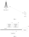
- FIG 1 is a simplified schematic diagram of a system architecture to which an embodiment of the present invention can be applied.
- the system architecture may include a base station 11 and UE 12.
- the base station 11 may be a wireless communications base station (Base Station, BS) or base station controller, or the like.
- the base station 11 may specifically include a user-plane base station and a control-plane base station.
- the base station 11 is an apparatus deployed in a radio access network to provide a wireless communication function for the UE 12.
- Main functions of the base station 11 include: managing a radio resource, compressing an Internet Protocol (Internet Protocol, IP) header, encrypting a user data flow, selecting a mobility management entity (Mobile Management Entity, MME) when user equipment performs attaching, routing user-plane data to a serving gateway (Service Gateway, SGW), organizing and sending a paging message, organizing and sending a broadcast message, performing measurement for a purpose of mobility or scheduling, configuring a measurement report, and the like.
- the base station 11 may include various forms of macro base stations, micro base stations, relay stations, access points, and the like. In systems that use different wireless access technologies, a device that functions as a base station may have different names.
- the device in an LTE system, the device is referred to as an evolved NodeB (Evolved NodeB, eNB or eNodeB); in a 3rd generation mobile communications technology (the third Generation Telecommunication, 3G) system, the device is referred to as a NodeB (Node B); and in a next-generation wireless communications system, the device is referred to as a gNB.
- the name "base station” may change.
- the base station 11 may be another apparatus that provides a wireless communication function for the UE 12.
- an apparatus that provides a wireless communication function for the UE 12 is referred to as the base station 11.
- the UE 12 may be a wireless terminal or a wired terminal.
- the wireless terminal may be a device that provides voice and/or data connectivity for a user, a handheld device with a wireless connection function, or another processing device connected to a wireless modem.
- the wireless terminal may communicate with one or more core networks through a radio access network (for example, Radio Access Network, RAN).
- the wireless terminal may be a mobile terminal, such as a mobile phone (also referred to as a "cellular" phone) or a computer with a mobile terminal, for example, may be a portable mobile apparatus, a pocket-sized mobile apparatus, a handheld mobile apparatus, a computer built-in mobile apparatus, or an in-vehicle mobile apparatus.
- Such mobile apparatuses exchange voice and/or data with the radio access network.
- the wireless terminal may be a device such as a personal communications service (Personal Communication Service, PCS) phone, a cordless phone, a Session Initiation Protocol (SIP) phone, a wireless local loop (WLL, Wireless Local Loop) station, or a personal digital assistant (Personal Digital Assistant, PDA).
- the wireless terminal may also be referred to as a system, a subscriber unit (Subscriber Unit), a subscriber station (Subscriber Station), a mobile station (Mobile Station), a mobile console (Mobile), a remote station (Remote Station), an access point (Access Point), a remote terminal (Remote Terminal), an access terminal (Access Terminal), a user terminal (User Terminal), or a user agent (User Agent).
- the UE 12 included in the system architecture in the present invention is a mobile phone.
- FIG 2 is a schematic composition diagram of a base station according to an embodiment of the present invention.
- the base station may include at least one processor 21, a memory 22, a transceiver 23, and a bus 24.
- the processor 21 is a control center of the base station, and may be one processor, or may be a collective name of a plurality of processing elements.
- the processor 21 is a central processing unit (Central Processing Unit, CPU), or may be an application-specific integrated circuit (Application-Specific Integrated Circuit, ASIC), or is configured as one or more integrated circuits for implementing the embodiments of the present invention, for example, one or more microprocessors (Digital Signal Processor, DSP), or one or more field programmable gate arrays (Field Programmable Gate Array, FPGA).
- CPU Central Processing Unit
- ASIC Application-Specific Integrated Circuit
- the processor 21 may perform various functions of the base station by running or executing a software program stored in the memory 22 and by invoking data stored in the memory 22.
- the base station may include a plurality of processors, for example, the processor 21 and a processor 25 shown in FIG 2 .
- Each of the processors may be a single-core (single-CPU) processor, or may be a multi-core (multi-CPU) processor.
- the processor herein may be one or more devices, circuits, and/or processing cores configured to process data (for example, a computer program instruction).
- the memory 22 may be a read-only memory (Read-Only Memory, ROM), another type of static storage device that can store static information and instructions, a random access memory (Random Access Memory, RAM), or another type of dynamic storage device that can store information and instructions; or may be an electrically erasable programmable read-only memory (Electrically Erasable Programmable Read-Only Memory, EEPROM), a compact disc read-only memory (Compact Disc Read-Only Memory, CD-ROM) or another compact disc storage, an optical disc storage (including a compact optical disc, a laser disc, an optical disc, a digital versatile disc, a Blu-ray disc, and the like), a magnetic disk storage medium or another magnetic storage device, or any other medium that can be used to carry or store expected program code in a form of an instruction or a data structure and that can be accessed by a computer.
- the memory 22 is not limited thereto.
- the memory 22 may exist independently and be connected to the processor 21 by using the bus 24. Alternatively, the
- the transceiver 23 is configured to communicate with another device or a communications network, for example, an Ethernet network, a radio access network (radio access network, RAN), or a wireless local area network (Wireless Local Area Networks, WLAN).
- the transceiver 23 may include all or a part of a baseband processor, and optionally, may further include an RF processor.
- the RF processor is configured to send or receive an RF signal.
- the baseband processor is configured to process a baseband signal converted from an RF signal, or a baseband signal to be converted into an RF signal.
- the bus 24 may be an industry standard architecture (Industry Standard Architecture, ISA) bus, a peripheral component interconnect (Peripheral Component Interconnect, PCI) bus, an extended industry standard architecture (Extended Industry Standard Architecture, EISA) bus, or the like.
- ISA Industry Standard Architecture
- PCI peripheral component interconnect
- EISA Extended Industry Standard Architecture
- the bus may be classified into an address bus, a data bus, a control bus, and the like. For ease of representation, only one bold line is used to represent the bus in FIG 2 , but this does not mean that there is only one bus or only one type of bus.
- the device structure shown in FIG 2 does not constitute a limitation on the base station.
- the base station may include more or fewer components than those shown in the figure, or some components may be combined, or a different component layout may be used.
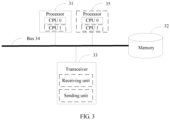
- FIG 3 is a schematic composition diagram of UE according to an embodiment of the present invention.
- the UE may include at least one processor 31, a memory 32, a transceiver 33, and a bus 34.
- the processor 31 may be one processor, or may be a collective name of a plurality of processing elements.
- the processor 31 may be a general purpose CPU, may be an ASIC, or may be one or more integrated circuits configured to control execution of a program of the solutions of the present invention, for example, one or more DSPs or one or more FPGAs.
- the processor 31 may perform various functions of the UE by running or executing a software program stored in the memory 32 and by invoking data stored in the memory 32.
- the processor 31 may include one or more CPUs.
- the processor 31 includes a CPU 0 and a CPU 1.
- the UE may include a plurality of processors.
- the UE includes the processor 31 and a processor 35.
- Each of the processors may be a single-CPU, or may be a multi-CPU.
- the processor herein may be one or more devices, a circuit, and/or a processing core configured to process data (for example, a computer program instruction).
- the transceiver 33 is configured to communicate with another device or a communications network, for example, Ethernet, a RAN, or a WLAN.
- the transceiver 33 may include a receiving unit to implement a receiving function, and a sending unit to implement a sending function.
- the bus 34 may be an ISA bus, a PCI bus, an EISA bus, or the like.
- the bus may be classified into an address bus, a data bus, a control bus, and the like. For ease of representation, only one bold line is used to represent the bus in FIG 3 , but this does not mean that there is only one bus or only one type of bus.
- the device structure shown in FIG 3 does not constitute a limitation on the UE.
- the UE may include more or fewer components than those shown in the figure, or some components may be combined, or a different component layout may be used.
- the UE may further include a battery, a camera, a Bluetooth module, a GPS module, a display screen, and the like. Details are not described herein.
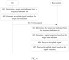
- FIG 4 is a flowchart of a signal transmission method according to an embodiment of the present invention. As shown in FIG 4 , the method may include the following steps.
- UE determines a target root indicator from a sequence indicator set.
- the sequence indicator set may be ⁇ A 1 , B 1 , A 2 , B 2 ,..., A s , B s ⁇ , or the sequence indicator set may be a subset of ⁇ A 1 , B 1 , A 2 , B 2 ,..., A s , B s ⁇ . Specifically, A i and B i appear in pairs in the subset.
- K is a length of a ZC sequence
- a quantity of elements included in the ZC sequence is K .
- the UE determines the sequence indicator set.
- the UE performs IDFT transform on the sequence Z q ' ( n ) to obtain a corresponding time-domain sequence, and performs ⁇ units of cyclic shifts on the time-domain sequence, to obtain a time-domain sequence obtained by performing IDFT transform on the sequence of the uplink signal.
- the UE directly obtains the sequence of the uplink signal based on the cyclic shift value and a formula e j ⁇ n Z q ' ( n ) .
- the cyclic shift value ⁇ may be a predefined fixed value, or a value determined from a plurality of values according to a predefined method.
- the UE may directly generate the sequence of the uplink signal based on the target root indicator and the cyclic shift value, without generating an intermediate parameter: the target ZC sequence.
- the UE may map, in an order of subcarrier indicators, the sequence whose length is N and that is of the uplink signal to N uniformly spaced subcarriers.
- the UE may map the generated sequence whose length is N to the N uniformly spaced subcarriers in descending order of the subcarrier indicators or in ascending order of the subcarrier indicators. This is not specifically limited herein in this embodiment of the present invention.
- FIG 5 shows an example in which the generated sequence whose length of N is mapped to the N uniformly spaced subcarriers in ascending order of the subcarrier indicators.
- the UE may receive second signaling that includes the cyclic shift value and that is sent by the base station, and generate the sequence of the uplink signal based on the cyclic shift value and the target root indicator, so as to generate the uplink signal.
- the base station may explicitly or implicitly notify the UE of the cyclic shift value through the second signaling.
- the explicitly notifying the UE of the cyclic shift value means that a value of the cyclic shift value is directly included in the second signaling.
- the implicitly notifying the UE of the cyclic shift value means that a parameter related to the cyclic shift value is included in the second signaling, where the parameter is used to determine a value of the cyclic shift value.
- the UE may receive third signaling that includes information about the cyclic shift value and that is sent by the base station, so as to generate the uplink signal based on the information about the cyclic shift value and the target root indicator.
- the UE may first determine the cyclic shift value based on the received information about the cyclic shift value, and then generate the uplink signal based on the determined cyclic shift value and the target root indicator.
- the third signaling may specifically include indication information of the cyclic shift value.
- the total cyclic shift value is divided into X portions, and the third signaling includes using an a th portion, where a is an integer greater than or equal to 1 and less than or equal to X.
- a value of a may be determined by the base station based on the cyclic shift value.
- the base station determines the cyclic shift value based on a cyclic shift value set, where an interval between any two cyclic shift values in the cyclic shift value set is greater than or equal to D.
- D is a positive real number satisfying 2 qn N K + ⁇ ⁇ D
- ⁇ is a positive real number
- n is a positive integer
- q is a positive integer less than or equal to s
- a q or B q is the target root indicator
- N is the length of the sequence of the uplink signal.
- the UE may determine, based on D and the third signaling that includes using the a th portion, the cyclic shift value selected by the base station.
- ⁇ 0 may be a value determined according to a predefined method, or may be indicated by the base station to the UE through the third signaling or other signaling.
- the base station or the UE may determine ⁇ based on ⁇ , or determine ⁇ based on a.
- D is a predefined value.
- the UE may receive sixth signaling sent by the base station, where the sixth signaling includes D.
- the UE may determine the cyclic shift value based on using the a th portion included in the third signaling and D included in the sixth signaling.
- the base station may explicitly or implicitly notify the UE of D through the sixth signaling.
- the explicitly notifying the UE of D means that a value of D is directly included in the sixth signaling.
- the implicitly notifying the UE of D means that a parameter related to D is included in the sixth signaling, where the parameter is used to determine a value of D.
- the UE may receive fourth signaling sent by the base station, where the fourth signaling includes ⁇ used to determine D .
- the UE may determine D based on ⁇ , q , and n , and then determine the cyclic shift value based on the determined D and using the a th portion included in the third signaling.
- ⁇ may also be predefined.
- the base station may explicitly or implicitly notify the UE of ⁇ through the fourth signaling.
- the explicitly notifying the UE of ⁇ means that a value of ⁇ is directly included in the fourth signaling.
- the implicitly notifying the UE of ⁇ means that a parameter related to ⁇ is included in the fourth signaling, where the parameter is used to determine a value of ⁇ .
- the third signaling, the fourth signaling, the fifth signaling, and the sixth signaling may be same signaling.
- the UE sends the uplink signal.
- a base station determines the target root indicator from the sequence indicator set.
- a specific process of determining, by the base station, the target root indicator may be as follows:
- the base station determines the sequence indicator set.
- the sequence indicator set may be ⁇ A 1 , B 1 , A 2 , B 2 ,..., A s , B s ⁇ , or the sequence indicator set may be a subset of ⁇ A 1 , B 1 , A 2 , B 2 ,..., A s , B s ⁇ . Specifically, A i and B i appear in pairs in the subset.
- the parameter s used to determine the sequence indicator set may be predefined, or may be determined by the base station. In addition, when s is not predefined, the base station needs to send the first signaling to the UE, to indicate s to the UE.
- a specific process of determining s by the base station may be: obtaining, by the base station, a maximum frequency deviation and a maximum delay spread, and determining s based on the maximum frequency deviation and the maximum delay spread.
- the maximum frequency deviation is a maximum frequency deviation between a center frequency for transmitting a signal by the base station and a center frequency for receiving a signal by each UE in a cell managed by the base station.
- the maximum frequency deviation may be predefined, or may be obtained by the base station through estimation, or may be determined by the base station based on a subcarrier spacing used for an uplink DMRS or an uplink SRS sent by the UE. For example, if the subcarrier spacing is relatively large, a system has relatively low sensitivity to a frequency deviation of the UE, and therefore an allowable maximum frequency deviation is relatively large. Therefore, the maximum frequency deviation may be determined based on the subcarrier spacing used for the uplink DMRS or the uplink SRS sent by the UE.
- the maximum delay spread is a maximum value of a cyclic shift value resulting from a delay spread caused by multipath.
- the maximum value of the cyclic shift value resulting from the delay spread may be obtained by the base station through estimation, may be predefined, or may be determined by the base station based on information such as a radius of a cell served by the base station.
- the base station may determine s based on an inequality 2 qn N K + ⁇ ⁇ D , where s is a maximum value of q satisfying the inequality, q is an integer greater than or equal to 0 and less than or equal to K /2, n is r or r + 1 , r is equal to a ratio of the maximum frequency deviation to the subcarrier spacing ⁇ f used for communication between the base station and the UE, N is a preset length of a signal sequence, K is a length of a ZC sequence, N ⁇ K , ⁇ is the maximum delay spread, and D is an interval between cyclic shift values when different UEs use a ZC sequence with a same root indicator.
- a range of a frequency deviation between the center frequency for transmitting a signal by the base station and the center frequency for receiving a signal by each UE in the cell managed by the base station is [ -r ⁇ f , r ⁇ f ]
- the target root indicator determined by the base station is q
- q is an integer greater than or equal to 0 and less than or equal to K /2 .
- the maximum frequency deviation r ⁇ f results in qn N K time units of cyclic shifts on a time-domain sequence obtained through IDFT transform
- the maximum frequency deviation -r ⁇ f results in - qn N K time units of cyclic shifts on a time-domain sequence obtained through IDFT transform.
- a range of the cyclic shift value resulting from the delay spread is [0, ⁇ ]. If it needs to be ensured that there is no interference between different UEs when there is a frequency deviation between a center frequency for receiving a signal by UE and the center frequency for transmitting a signal by the base station, and there is a delay spread, 2 qn N K + ⁇ ⁇ D needs to be ensured.
- the base station may jointly determine s and the interval D based on a plurality of currently available root indicators, so that s and D satisfy an inequality 2 sn N K + ⁇ ⁇ D .
- the base station can determine the sequence indicator set.
- the base station determines the target root indicator from the sequence indicator set.
- the base station generates a signal sequence based on the target root indicator.
- the signal sequence is a sequence generated based on a target ZC sequence.
- a root indicator of the target ZC sequence is the target root indicator.
- a specific process of generating, by the base station, the information sequence based on the target root indicator may be as follows:
- the base station generates the target ZC sequence based on the target root indicator.
- a specific implementation process of generating the target ZC sequence based on the target root indicator in step 405 is similar to the specific implementation process of generating the target ZC sequence based on the target root indicator in step 402 in this embodiment of the present invention. Details are not described herein again in this embodiment of the present invention.
- the base station uses the target ZC sequence as a sequence generated based on the ZC sequence, or truncates or cyclically extends the target ZC sequence to obtain a sequence generated based on the target ZC sequence. Further, the base station obtains the signal sequence based on the cyclic shift value and the sequence that is generated based on the target ZC sequence.
- a specific implementation process of obtaining, by the base station, the signal sequence based on the cyclic shift value and the sequence that is generated based on the target ZC sequence is similar to the specific implementation process in step 402 in this embodiment of the present invention. Details are not described herein again in this embodiment of the present invention.
- the base station directly generates the signal sequence based on a target root sequence and the cyclic shift value, without generating an intermediate variable: the target ZC sequence.
- the base station may send the second signaling to the UE, where the second signaling includes the cyclic shift value, and the cyclic shift value is correlated with the UE, so that the UE can generate the uplink signal based on the cyclic shift value and the determined target root indicator.
- the base station may send the third signaling to the UE, where the third signaling includes the information about the cyclic shift value, and the information about the cyclic shift value is correlated with the UE, so that the UE can generate the uplink signal based on the information about the cyclic shift value and the determined target root indicator.
- the cyclic shift value is determined based on the cyclic shift value set. An interval between any two cyclic shift values in the cyclic shift value set is greater than or equal to D .
- D is a positive real number satisfying 2 qn N K + ⁇ ⁇ D .
- D is predefined; or the base station may notify the UE of D through the sixth signaling; or the base station may send the fourth signaling to the UE, where the fourth signaling includes ⁇ used to determine D ; or the base station may send the fifth signaling to the UE, where the fifth signaling includes n used to determine D.
- the base station may determine n based on a frequency deviation.
- the base station may determine ⁇ based on a delay spread.
- ⁇ may also be predefined.
- n may also be predefined.
- a method for determining the information about the cyclic shift value included in the third signaling is similar to the specific implementation process in step 402 in this embodiment of the present invention. Details are not described herein again in this embodiment of the present invention.
- the base station receives the uplink signal.
- the base station processes the uplink signal based on the signal sequence.
- the base station may process the uplink signal based on the generated signal sequence. For example, the base station may process the uplink signal based on the signal sequence to obtain a channel estimation result or to perform signal detection. For example, the base station may perform correlation on the uplink signal based on the signal sequence.
- the first signaling, the second signaling, the third signaling, the fourth signaling, the fifth signaling, and the sixth signaling may be higher layer signaling, for example, radio resource control (Radio Resource Control, RRC) signaling, multiple access control signaling (Multiple Access Control Control Element, MAC CE), or downlink control signaling carrying downlink control information (Downlink Control Information, DCI).
- RRC Radio Resource Control
- MAC CE Multiple Access Control Control Element
- DCI Downlink Control Information
- the base station generates the signal sequence based on the target root indicator determined from the sequence indicator set, and processes the received uplink signal based on the generated signal sequence.
- the sequence indicator set is ⁇ A 1 , B 1 , A 2 , B 2 ,..., A s , B s ⁇ , s is an integer greater than or equal to 1 and less than or equal to K / 2 ⁇ 1 , and the sequence indicator set does not include a root indicator K / 2 or K ⁇ K / 2 , or s is a positive integer less than K / 2 ⁇ 1 among integers greater than or equal to 1 and less than or equal to K / 2 ⁇ 1 .
- a relationship between a root indicator and the interval D is constrained by using the inequality 2 qn N K + ⁇ ⁇ D .
- Jointly determining s (an upper limit of q satisfying the foregoing inequality) and the interval D based on the foregoing inequality can ensure that a total cyclic shift of the UE resulting from the frequency deviation and the delay spread can fall within the interval D , without occupying an additional cyclic shift beyond the cyclic shift interval. This can ensure that there is no interference between different UEs.
- a value of s may be further limited, for example, to a relatively small value such as 1, 2, or 3.
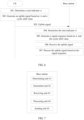
- FIG 6 is a flowchart of another signal transmission method according to an embodiment of the present invention. As shown in FIG 6 , the method may include the following steps.
- UE determines a root indicator q .
- the method is described based on the frequency-domain root indicator q . However, optionally, the method may be alternatively described based on the corresponding time-domain root indicator p.
- the UE generates an uplink signal based on q and a cyclic shift value.
- the cyclic shift value is determined by the UE based on a cyclic shift value set.
- the cyclic shift value set is ⁇ 0 mod N , ⁇ 0 + D mod N , ... , ⁇ 0 + N D ⁇ 1 D mod N .
- the cyclic shift value set is determined based on q , D is a positive real number, ⁇ 0 is a real number and is initial cyclic shift information, ⁇ ⁇ indicates rounding down, and N is a length of a sequence of the uplink signal.
- q may alternatively belong to a set ⁇ A 1 , B 1 , A 2 , B 2 ,..., A s , B s ⁇ or a subset of ⁇ A 1 , B 1 , A 2 , B 2 ,..., A s , B s ⁇ .
- a i and B i appear in pairs in the subset.
- a i i (mod K )
- B i -i (mod K )
- a i and B i are root indicators of ZC sequences, i is an integer greater than or equal to 1 and less than or equal to s , s is an integer greater than or equal to 1 and less than or equal to K / 2 ⁇ 1 , and ⁇ ⁇ indicates rounding down.
- the UE may select a cyclic shift value from the set according to a predefined rule. For example, the UE selects the cyclic shift value based on an order of all cyclic shift values in the set and according to the predefined rule.
- the UE may receive signaling sent by a base station, where the signaling includes a cyclic shift value of the UE.
- the signaling can include any one of cyclic shift values in the set.
- the UE may first determine the cyclic shift value set in the following manners:
- the UE may receive first signaling sent by the base station, where the first signaling includes D corresponding to q .
- the UE may determine the cyclic shift value set based on D .
- the first signaling may notify D respectively corresponding to a plurality of q .
- the first signaling may notify ( q 1 , D 1 ),( q 2 , D 2 ),( q 3 , D 3 ) .
- the UE determines, according to a predefined rule, a root indicator q ⁇ ⁇ q 1 , q 2 , q 3 ⁇ currently used for sending an uplink signal, so as to know a currently used interval D .
- a possible value of D corresponding to each root indicator q is one or more predefined values.
- the possible value may be predefined by using a table.
- the first signaling may include one of a plurality of possible values of D corresponding to one q .
- the first signaling may be RRC signaling, a MAC CE, or downlink control signaling carrying DCI.
- the UE may receive second signaling sent by the base station, where the second signaling includes ⁇ , and ⁇ is a parameter related to a maximum delay spread.
- ⁇ is a cyclic shift value resulting from the maximum delay spread.
- the UE may determine the cyclic shift value set based on q and ⁇ .
- D used to determine the cyclic shift value set is a positive real number satisfying 2 q mod K n N K + ⁇ ⁇ D .
- D used to determine the cyclic shift value set is a positive real number satisfying 2 K ⁇ q mod K n N K + ⁇ ⁇ D , where n is a positive integer, and K is a length of a ZC sequence.
- n is predefined.
- the base station may notify the UE of n through signaling.
- the second signaling may be RRC signaling, a MAC CE, or downlink control signaling carrying DCI.
- the UE may receive third signaling sent by the base station, where the third signaling includes a cyclic shift value set ⁇ 0 mod N , ⁇ 0 + D mod N , ... , ⁇ 0 + N D ⁇ 1 D mod N corresponding to q .
- the third signaling may be RRC signaling, a MAC CE, or downlink control signaling carrying DCI.
- the initial cyclic shift information is required for determining the cyclic shift value set.
- the initial cyclic shift information may be predefined; or the UE may receive fourth signaling sent by the base station, where the fourth signaling includes the initial cyclic shift information.
- the fourth signaling may be RRC signaling, a MAC CE, or downlink control signaling carrying DCI.
- the UE sends the uplink signal.
- a base station determines the root indicator q .
- the base station generates a signal sequence based on q and the cyclic shift value.
- the base station may send, to the UE in the following manners, a parameter used to determine the cyclic shift value set:
- the initial cyclic shift information is required for determining the cyclic shift value set.
- the initial cyclic shift information may be predefined; or the base station sends the fourth signaling to the UE, where the fourth signaling includes the initial cyclic shift information.
- the base station receives the uplink signal.
- the base station processes the uplink signal based on the signal sequence.
- step 501 to step 507 in this embodiment of the present invention are similar to specific descriptions of corresponding content in step 401 to step 407 in another embodiment of the present invention.
- step 501 to step 507 in this embodiment of the present invention refer to the specific descriptions of the corresponding content in step 401 to step 407 in the another embodiment. Details are not described herein again in this embodiment of the present invention.
- a root indicator q of a ZC sequence used to generate a preamble needs to be greater than a value.
- a root indicator of a ZC sequence used to generate a preamble needs to be greater than a maximum delay spread. Therefore, according to the method in this embodiment of the present invention, a quantity of available root indicators is increased, thereby increasing a quantity of preambles.
- a root indicator q or K - q of a ZC sequence corresponding to a q value that is a relatively small positive integer may be selected.
- a cyclic shift value that can be used by the UE and a cyclic shift value that can be allocated by the base station are determined based on the set ⁇ 0 mod N , ⁇ 0 + D mod N , ... , ⁇ 0 + N D ⁇ 1 D mod N , where D is a value determined based on q .
- Properly determining a value of D based on q can ensure that cyclic shifts of the UE resulting from a frequency deviation and a delay spread can fall within a cyclic shift interval allocated by the base station, without occupying an additional cyclic shift beyond the cyclic shift interval allocated by the base station. This can ensure that there is no inter-user interference.
- selection of a root indicator q needs to meet a value limitation that the root indicator q is greater than a value.
- a root indicator q selected in such a way only some of elements in the set can be selected as available cyclic shift values, to ensure that there is no inter-user interference. Therefore, according to the method in this embodiment of the present invention, a quantity of available cyclic shift values is increased, thereby further increasing a quantity of preamble sequences.
- a cyclic shift value that can be used by the UE and a cyclic shift value that can be allocated by the base station are all elements in the set ⁇ 0 mod N , ⁇ 0 + D mod N , ... , ⁇ 0 + N D ⁇ 1 D mod N .
- a supported quantity of UEs that perform orthogonal code division multiplexing through cyclic shifts is larger on a same time-frequency resource, thereby improving utilization of an uplink time-frequency resource.
- the network elements such as the base station and the UE include corresponding hardware structures and/or software modules for performing the functions.
- the present invention can be implemented by hardware or a combination of hardware and computer software. Whether a function is performed by hardware or hardware driven by computer software depends on particular applications and design constraints of the technical solutions. A person skilled in the art may use different methods to implement the described functions for each particular application, but it should not be considered that the implementation goes beyond the scope of the present invention.
- functional modules of the base station and the UE may be divided based on the foregoing method examples.
- the functional modules may be divided based on the corresponding functions, or two or more functions may be integrated in one processing module.
- the integrated module may be implemented in a form of hardware, or may be implemented in a form of a software functional module.
- the module division in the embodiments of the present invention is an example, and is merely logical function division. During actual implementation, there may be another division manner.
- FIG 7 is a possible schematic composition diagram of the base station in the foregoing embodiments.
- the base station may include: a determining unit 61, a generation unit 62, a receiving unit 63, and a processing unit 64.
- the determining unit 61 is configured to support the base station in performing step 404 in the signal transmission method shown in FIG 4 , and step 504 in the signal transmission method shown in FIG 6 .
- the generation unit 62 is configured to support the base station in performing step 405 in the signal transmission method shown in FIG 4 , and step 505 in the signal transmission method shown in FIG 6 .
- the receiving unit 63 is configured to support the base station in performing step 406 in the signal transmission method shown in FIG 4 , and step 506 in the signal transmission method shown in FIG 6 .
- the processing unit 64 is configured to support the base station in performing step 407 in the signal transmission method shown in FIG 4 , and step 507 in the signal transmission method shown in FIG 6 .
- the base station may further include a sending unit 65.
- the sending unit 65 is configured to support the base station in performing the processes of sending the first signaling, the second signaling, the third signaling, the fourth signaling, the fifth signaling, and the sixth signaling in the embodiments corresponding to FIG 4 and FIG 5 .
- FIG 8 is another possible schematic composition diagram of the based station in the foregoing embodiments.
- the base station includes: a processing module 71 and a communications module 72.
- the processing module 71 may be a processor or a controller.
- the processor or the controller may implement or execute various example logical blocks, modules, and circuits described with reference to content disclosed in the present invention.
- the processor may be a combination for implementing a computing function, for example, a combination of one or more microprocessors, or a combination of a DSP and a microprocessor.
- the communications module 72 may be a transceiver, a transceiver circuit, a communications interface, or the like.
- the storage module 73 may be a memory.
- the base station in this embodiment of the present invention may be the base station shown in FIG 2 .
- FIG 9 is a possible schematic composition diagram of the UE in the foregoing embodiments.
- the UE may include: a determining unit 81, a generation unit 82, and a sending unit 83.
- the determining unit 81 is configured to support the UE in performing step 401 in the signal transmission method shown in FIG 4 , and step 501 in the signal transmission method shown in FIG 6 .
- the generation unit 82 is configured to support the UE in performing step 402 in the signal transmission method shown in FIG 4 , and step 502 in the signal transmission method shown in FIG 6 .
- the UE may further include a receiving unit 84.
- the receiving unit 84 is configured to support the UE in performing the processes of receiving the first signaling, the second signaling, the third signaling, the fourth signaling, the fifth signaling, and the sixth signaling in the embodiments corresponding to FIG 4 and FIG 5 .
- the UE provided in this embodiment of the present invention is configured to perform the foregoing signal transmission method, and therefore can achieve a same effect as the foregoing signal transmission method.
- FIG 10 is another possible schematic composition diagram of the UE in the foregoing embodiments.
- the UE includes: a processing module 91 and a communications module 92.
- the processing module 91 is configured to control and manage actions of the UE.
- the communications module 92 is configured to support the UE in communicating with another network entity, for example, communicating with a functional module or a network entity shown in FIG 1, FIG 2 , FIG 7 , or FIG 8 .
- the UE may further include a storage module 93, configured to store program code and data of a terminal.
- the processing module 91 may be a processor or a controller.
- the processor or the controller may implement or execute various example logical blocks, modules, and circuits described with reference to content disclosed in the present invention.
- the processor may be a combination for implementing a computing function, for example, a combination of one or more microprocessors, or a combination of a DSP and a microprocessor.
- the communications module 92 may be a transceiver, a transceiver circuit, a communications interface, or the like.
- the storage module 93 may be a memory.
- the terminal device in this embodiment of the present invention may be the terminal device shown in FIG 3 .
- the disclosed apparatuses and methods may be implemented in other manners.
- the described apparatus embodiments are merely examples.
- the module or unit division is merely logical function division, and there may be another division manner during actual implementation.
- a plurality of units or components may be combined or may be integrated into another apparatus, or some features may be ignored or may not be performed.
- the shown or discussed mutual couplings or direct couplings or communications connections may be implemented through some interfaces.
- the indirect couplings or communications connections between the apparatuses or units may be implemented in electrical, mechanical, or other forms.
- the units described as separate parts may or may not be physically separated, and parts shown as units may be one or more physical units, may be located in one position, or may be distributed in a plurality of different positions. Some or all of the units may be selected depending on actual requirements, to achieve the objectives of the solutions of the embodiments.
- functional units in the embodiments of the present invention may be integrated into one processing unit, or each of the units may exist alone physically, or two or more units may be integrated into one unit.
- the integrated unit may be implemented in a form of hardware, or may be implemented in a form of a software functional unit.
- the integrated unit When the integrated unit is implemented in the form of the software functional unit and sold or used as an independent product, the integrated unit may be stored in a readable storage medium.
- the software product is stored in a storage medium and includes several instructions for instructing a device (which may be a single-chip microcomputer, a chip, or the like) or a processor (processor) to perform all or some of the steps in the methods described in the embodiments of the present invention.
- the storage medium includes any medium that can store program code, such as a USB flash drive, a removable hard disk, a read-only memory (Read-Only Memory, ROM), a random access memory (Random Access Memory, RAM), a magnetic disk, or an optical disc.
- program code such as a USB flash drive, a removable hard disk, a read-only memory (Read-Only Memory, ROM), a random access memory (Random Access Memory, RAM), a magnetic disk, or an optical disc.
Landscapes
- Engineering & Computer Science (AREA)
- Signal Processing (AREA)
- Computer Networks & Wireless Communication (AREA)
- Power Engineering (AREA)
- Mobile Radio Communication Systems (AREA)
Description
- Embodiments of the present invention relate to the communications field, and in particular, to a signal transmission method, a signal receiving method, and a device.
-
WO 2016 169 062 A1 describes a method and device for uplink random access for improving a success rate of uplink random access when uplink frequency offset is large, and being capable of increasing the success rate of uplink random access when the uplink frequency offset is large.
In a wireless communications system, user equipment (User Equipment, UE) sends a pilot sequence to a base station, and the base station may learn channel state information of the UE by detecting the pilot sequence, and detect, by using the channel state information, data sent by the UE. A ZC (Zadoff-Chu) sequence is a constant-amplitude zero-autocorrelation sequence. A time-domain sequence obtained by modulating a sequence generated based on the ZC sequence to a frequency domain and then performing inverse discrete Fourier transform (Inverse Discrete Fourier Transform, IDFT) has a relatively low peak-to-average power ratio (Peak average power ratio, PAPR). Therefore, using the sequence generated based on the ZC sequence as the pilot sequence instead of using a sequence with a relatively high peak-to-average power ratio helps improve a transmitter power efficiency of the UE. The sequence generated based on the ZC sequence may be the ZC sequence itself, or a sequence generated by truncating or cyclically extending the ZC sequence. Currently, the ZC sequence has been widely applied to a long term evolution (Long Term Evolution, LTE) wireless communications system as a pilot sequence. Specifically, the ZC sequence may be applied to an uplink signal in LTE. For example, the sequence generated based on the ZC sequence is used as an uplink sounding reference signal (Sounding Reference Signals, SRS) or an uplink demodulation reference signal (DeModulation Reference Signal, DMRS). The sequence generated based on the ZC sequence may be alternatively used as a modulation sequence of an uplink control channel. To be specific, sequence modulation is performed on to-be-sent symbols by using the sequence generated based on the ZC sequence, and information obtained through sequence modulation is carried on a time-frequency resource of the uplink control channel. In the LTE system, the ZC sequence may also be used to generate a preamble. The preamble is used by UE to initiate uplink random access, so that a base station obtains uplink timing information of the UE. This helps the UE achieve uplink synchronization. - One frequency-domain ZC sequence may be determined based on one root indicator. Further, different sequences may be obtained by performing different cyclic shifts on a sequence generated based on the ZC sequence. Performing a cyclic shift on a sequence generated based on one frequency-domain ZC sequence means performing a (time-domain) cyclic shift on a time-domain sequence obtained by performing IDFT transform on the sequence generated based on the ZC sequence. Assuming that a sequence z(n)(n = 0,...,N -1) represents a frequency-domain sequence whose length is N and that is generated based on a ZC sequence, it can be learned, from a property of a sequence generated based on a ZC sequence, that IDFT transform is first performed on the frequency-domain sequence z(n)(n = 0,...,N -1) to obtain a corresponding time-domain sequence, and then l units of cyclic shifts are performed on the time-domain sequence. This is equivalent to first performing phase rotation on the sequence z(n) in frequency domain to obtain a sequence


- The prior art has at least the following problem: In an actual application scenario, there is a frequency deviation between a center frequency for receiving a signal by UE and a center frequency for transmitting a signal by a base station. When the frequency deviation is greater than a subcarrier spacing used for communication between the base station and the UE, the frequency deviation results in an additional time-domain cyclic shift on a sequence obtained based on a root indicator allocated by the base station to the UE. Therefore, the base station needs to reserve more cyclic shift values for the UE. In this case, when the frequency deviation is greater than the subcarrier spacing used for communication between the base station and the UE, to ensure that no interference is generated between different UEs that transmit sequences by using a same time-frequency-domain resource, a quantity of cyclic shift values that can be allocated is reduced, that is, a supported quantity of UEs that perform orthogonal code division multiplexing through cyclic shifts is relatively small. As a result, uplink resource utilization is reduced.
- Embodiments of the present invention provide a signal transmission method, a signal receiving method, and a device, so as to resolve a problem that a supported quantity of UEs that perform orthogonal code division multiplexing through cyclic shifts is relatively small when a frequency deviation between a center frequency for receiving a signal by UE and a center frequency for transmitting a signal by a base station is greater than a subcarrier spacing used for communication between the base station and the UE.
- The invention is set out in the appended set of claims.
-
-
FIG 1 is a simplified schematic diagram of a system architecture to which an embodiment of the present invention is applied according to an embodiment of the present invention; -
FIG 2 is a schematic composition diagram of a base station according to an embodiment of the present invention; -
FIG 3 is a schematic composition diagram of UE according to an embodiment of the present invention; -
FIG 4 is a flowchart of a signal transmission method according to an embodiment of the present invention; -
FIG 5 is a schematic diagram of sequence mapping according to an embodiment of the present invention; -
FIG 6 is a flowchart of another signal transmission method according to an embodiment of the present invention; -
FIG 7 is a schematic composition diagram of another base station according to an embodiment of the present invention; -
FIG 8 is a schematic composition diagram of another base station according to an embodiment of the present invention; -
FIG 9 is a schematic composition diagram of another UE according to an embodiment of the present invention; and -
FIG 10 is a schematic composition diagram of another UE according to an embodiment of the present invention. - A base station may allocate a root indicator of a same ZC sequence to different UEs, and also allocate cyclic shift values (l 1, l 2) satisfying l 1 mod N ≠ l 2 mod N, so as to implement multiplexing of a plurality of UEs on a same time-frequency-domain resource. However, in an actual application scenario, there is a frequency deviation between a center frequency for receiving a signal by UE and a center frequency for transmitting a signal by a base station. In addition, when a capability of the UE is relatively poor or the UE is in a high-speed moving state, or in another case (for example, a small subcarrier spacing is used because a long cyclic prefix (Cyclic Prefix, CP) is required), the frequency deviation is greater than a subcarrier spacing used for communication between the base station and the UE. This results in an additional time-domain cyclic shift on a sequence obtained based on a root indicator allocated by the base station to the UE. Therefore, the base station needs to reserve more cyclic shift values for the UE.
- For example, the base station allocates a root indicator
UE 1, and predefines a length N=61 of a sequence generated based on a ZC sequence (where a root indicator of the ZC sequence is
UE 1 and a center frequency for transmitting a signal by the base station, because additional time-domain cyclic shifts resulting from the frequency deviation occupy two cyclic shift locations, the two cyclic shift locations need to be reserved for the UE 1. Therefore, when the base station allocates a cyclic shift value to another UE, the two cyclic shift locations occupied by the additional cyclic shifts resulting from the frequency deviation of theUE 1 can no longer be allocated. As a result, a quantity of cyclic shift values that can be allocated is reduced, that is, a supported quantity of UEs that perform orthogonal code division multiplexing through cyclic shifts is relatively small, reducing uplink resource utilization. - To resolve a problem that a supported quantity of UEs that perform orthogonal code division multiplexing through cyclic shifts is relatively small when a frequency deviation between a center frequency for receiving a signal by UE and a center frequency for transmitting a signal by a base station is greater than a subcarrier spacing used for communication between the base station and the UE, embodiments of the present invention provide a signal transmission method, a signal receiving method, and a device. A basic principle thereof is as follows: A base station determines a target root indicator from a sequence indicator set, and generates a signal sequence based on the target root indicator; and the base station receives an uplink signal, and processes the uplink signal based on the generated signal sequence. The sequence indicator set is {A 1 , B 1 , A 2 , B 2 ,···, As, Bs }, Ai =i(mod K), Bi =-i(mod K), Ai and Bi are root indicators of ZC sequences, i is an integer greater than or equal to 1 and less than or equal to s, s is an integer greater than or equal to 1 and less than or equal to


- Using the root indicator

- It is assumed that a range of a frequency deviation between a center frequency for transmitting a signal by a base station and a center frequency for receiving a signal by each UE in a cell managed by the base station is [-rΔf,rΔf], where Δf is a subcarrier spacing used for communication between the base station and the UE. It is assumed that a target root indicator determined by the base station is q, and a length of a (frequency-domain) signal sequence generated by the base station based on the target root indicator q is N. In this case, the maximum frequency deviation rΔf results in


- In addition, in the prior art, when UE encounters uplink out-of-synchronization, that is, out-of-synchronization with a base station in uplink transmission, the UE needs to send a preamble to the base station, so that the base station determines uplink timing information of the UE based on the preamble, to help the UE perform uplink synchronization. The preamble is a time-domain sequence generated based on a ZC sequence. One preamble may be generated based on one time-domain ZC sequence (having a time-domain root indicator u ) and based on a cyclic shift value, or may be generated according to the foregoing method and based on a frequency-domain ZC sequence (having a frequency-domain root indicator p ) corresponding to the time-domain ZC sequence. The two methods are equivalent. In addition, if the root indicator u of the time-domain ZC sequence is known, the corresponding frequency-domain root indicator p is a minimum non-negative integer satisfying (pu)mod K =1, where K is a length of the time-domain ZC sequence and the corresponding frequency-domain ZC sequence. Without loss of generality, this specification provides descriptions by using an example in which a preamble is generated based on a frequency-domain ZC sequence. The UE may determine the root indicator of the ZC sequence and the cyclic shift value according to a predefined rule or by receiving signaling from the base station, so as to generate the preamble. Because the UE encounters the uplink out-of-synchronization, a CP of the preamble is relatively long. To resolve a problem of excessively low energy efficiency resulting from an excessively long CP, a subcarrier spacing used by the UE to send the preamble is usually quite small. Therefore, when there is a frequency deviation between a center frequency for sending a signal by the UE and a center frequency for receiving a signal by the base station, the frequency deviation is usually greater than a subcarrier spacing used for communication between the base station and the UE. To make the base station obtain accurate uplink timing information, the root indicator of the ZC sequence needs to ensure that an additional cyclic shift resulting from the frequency deviation and a cyclic shift resulting from a delay spread can be distinguished. Therefore, an LTE system imposes a constraint that a root indicator q of a ZC sequence used to generate a preamble needs to be greater than a value while satisfying 0 ≤ q < K/2. For example, the root indicator q needs to be greater than a cyclic shift resulting from a maximum delay spread. Therefore, in the prior art, a quantity of root indicators of ZC sequences used to generate preambles is relatively limited. In addition, for each available root indicator of a ZC sequence, the base station needs to allocate different cyclic shift values to different UEs. To ensure that there is no interference between different UEs, both a cyclic shift resulting from a frequency deviation of one UE and a cyclic shift resulting from a delay spread need to be reserved for the UE, and cannot be allocated to another UE. Therefore, a quantity of available cyclic shift values is also relatively limited. To sum up, in the prior art, a quantity of available preamble sequences is relatively limited.
- In some scenarios, although UE is in an uplink out-of-synchronization state, only a small amount of information needs to be transmitted, and a base station does not need to obtain uplink timing information. In these scenarios, directly using the prior art results in a very limited quantity of available preambles. For example, due to moving, the UE needs to be handed over to another cell, or handed over to an area covered by another transmitter and receiver point (Transmitter and Receiver Point, TRP) in a current cell. In this case, a requirement of the UE is to send a preamble, so that the base station knows a location of the UE in a network. Therefore, uplink timing information is not required. In this case, a root indicator of a ZC sequence used to generate a preamble does not need to ensure that an additional cyclic shift resulting from a frequency deviation and a cyclic shift resulting from a delay spread can be distinguished. Therefore, in these scenarios, directly using the prior art results in a very limited quantity of available preamble sequences.
- To resolve a problem that directly using the prior art results in a very limited quantity of available preambles when UE is in an uplink out-of-synchronization state and needs to transmit uplink data but a base station does not need to obtain uplink timing information, embodiments of the present invention provide another signal transmission method and signal receiving method. A basic principle thereof is as follows: UE determines a root indicator q, and the UE generates an uplink signal based on q and a cyclic shift value, where the cyclic shift value is determined by the UE based on a cyclic shift value set, and the cyclic shift value set is as follows:

- In the methods in the embodiments of the present invention, there is no value limitation that a root indicator q of a ZC sequence used to generate a preamble needs to be greater than a value. For example, in the prior art, a root indicator of a ZC sequence used to generate a preamble needs to be greater than a maximum delay spread. Therefore, according to the methods in the embodiments of the present invention, a quantity of available root indicators is increased, thereby increasing a quantity of preambles. For example, in the prior art, q = 1 cannot be used. However, in the methods in the embodiments of the present invention, q = 1 can be used. Usually, a root indicator q or K - q of a ZC sequence corresponding to a q value that is a relatively small positive integer may be selected. In addition, for a selected root indicator q, a cyclic shift value that can be used by the UE is determined based on the
set 
- The following describes implementations of the embodiments of the present invention in detail with reference to accompanying drawings.
-
FIG 1 is a simplified schematic diagram of a system architecture to which an embodiment of the present invention can be applied. As shown inFIG 1 , the system architecture may include abase station 11 andUE 12. - The
base station 11 may be a wireless communications base station (Base Station, BS) or base station controller, or the like. Thebase station 11 may specifically include a user-plane base station and a control-plane base station. Thebase station 11 is an apparatus deployed in a radio access network to provide a wireless communication function for theUE 12. Main functions of thebase station 11 include: managing a radio resource, compressing an Internet Protocol (Internet Protocol, IP) header, encrypting a user data flow, selecting a mobility management entity (Mobile Management Entity, MME) when user equipment performs attaching, routing user-plane data to a serving gateway (Service Gateway, SGW), organizing and sending a paging message, organizing and sending a broadcast message, performing measurement for a purpose of mobility or scheduling, configuring a measurement report, and the like. Thebase station 11 may include various forms of macro base stations, micro base stations, relay stations, access points, and the like. In systems that use different wireless access technologies, a device that functions as a base station may have different names. For example, in an LTE system, the device is referred to as an evolved NodeB (Evolved NodeB, eNB or eNodeB); in a 3rd generation mobile communications technology (the third Generation Telecommunication, 3G) system, the device is referred to as a NodeB (Node B); and in a next-generation wireless communications system, the device is referred to as a gNB. With evolution of communications technologies, the name "base station" may change. In addition, in another possible case, thebase station 11 may be another apparatus that provides a wireless communication function for theUE 12. For ease of description, in this embodiment of the present invention, an apparatus that provides a wireless communication function for theUE 12 is referred to as thebase station 11. - The
UE 12 may be a wireless terminal or a wired terminal. The wireless terminal may be a device that provides voice and/or data connectivity for a user, a handheld device with a wireless connection function, or another processing device connected to a wireless modem. The wireless terminal may communicate with one or more core networks through a radio access network (for example, Radio Access Network, RAN). The wireless terminal may be a mobile terminal, such as a mobile phone (also referred to as a "cellular" phone) or a computer with a mobile terminal, for example, may be a portable mobile apparatus, a pocket-sized mobile apparatus, a handheld mobile apparatus, a computer built-in mobile apparatus, or an in-vehicle mobile apparatus. Such mobile apparatuses exchange voice and/or data with the radio access network. For example, the wireless terminal may be a device such as a personal communications service (Personal Communication Service, PCS) phone, a cordless phone, a Session Initiation Protocol (SIP) phone, a wireless local loop (WLL, Wireless Local Loop) station, or a personal digital assistant (Personal Digital Assistant, PDA). The wireless terminal may also be referred to as a system, a subscriber unit (Subscriber Unit), a subscriber station (Subscriber Station), a mobile station (Mobile Station), a mobile console (Mobile), a remote station (Remote Station), an access point (Access Point), a remote terminal (Remote Terminal), an access terminal (Access Terminal), a user terminal (User Terminal), or a user agent (User Agent). In an embodiment, as shown inFIG 1 , theUE 12 included in the system architecture in the present invention is a mobile phone. -
FIG 2 is a schematic composition diagram of a base station according to an embodiment of the present invention. As shown inFIG 2 , the base station may include at least oneprocessor 21, amemory 22, atransceiver 23, and a bus 24. - The following specifically describes the constituent parts of the base station with reference to
FIG 2 . - The
processor 21 is a control center of the base station, and may be one processor, or may be a collective name of a plurality of processing elements. For example, theprocessor 21 is a central processing unit (Central Processing Unit, CPU), or may be an application-specific integrated circuit (Application-Specific Integrated Circuit, ASIC), or is configured as one or more integrated circuits for implementing the embodiments of the present invention, for example, one or more microprocessors (Digital Signal Processor, DSP), or one or more field programmable gate arrays (Field Programmable Gate Array, FPGA). - The
processor 21 may perform various functions of the base station by running or executing a software program stored in thememory 22 and by invoking data stored in thememory 22. - During specific implementation, in an embodiment, the
processor 21 may include one or more CPUs, for example, aCPU 0 and aCPU 1 shown inFIG 2 . - During specific implementation, in an embodiment, the base station may include a plurality of processors, for example, the
processor 21 and aprocessor 25 shown inFIG 2 . Each of the processors may be a single-core (single-CPU) processor, or may be a multi-core (multi-CPU) processor. The processor herein may be one or more devices, circuits, and/or processing cores configured to process data (for example, a computer program instruction). - The
memory 22 may be a read-only memory (Read-Only Memory, ROM), another type of static storage device that can store static information and instructions, a random access memory (Random Access Memory, RAM), or another type of dynamic storage device that can store information and instructions; or may be an electrically erasable programmable read-only memory (Electrically Erasable Programmable Read-Only Memory, EEPROM), a compact disc read-only memory (Compact Disc Read-Only Memory, CD-ROM) or another compact disc storage, an optical disc storage (including a compact optical disc, a laser disc, an optical disc, a digital versatile disc, a Blu-ray disc, and the like), a magnetic disk storage medium or another magnetic storage device, or any other medium that can be used to carry or store expected program code in a form of an instruction or a data structure and that can be accessed by a computer. However, thememory 22 is not limited thereto. Thememory 22 may exist independently and be connected to theprocessor 21 by using the bus 24. Alternatively, thememory 22 may be integrated with theprocessor 21. - The
memory 22 is configured to store a software program for executing the solutions of the present invention, and theprocessor 21 controls execution of the software program. - The
transceiver 23 is configured to communicate with another device or a communications network, for example, an Ethernet network, a radio access network (radio access network, RAN), or a wireless local area network (Wireless Local Area Networks, WLAN). Thetransceiver 23 may include all or a part of a baseband processor, and optionally, may further include an RF processor. The RF processor is configured to send or receive an RF signal. The baseband processor is configured to process a baseband signal converted from an RF signal, or a baseband signal to be converted into an RF signal. - The bus 24 may be an industry standard architecture (Industry Standard Architecture, ISA) bus, a peripheral component interconnect (Peripheral Component Interconnect, PCI) bus, an extended industry standard architecture (Extended Industry Standard Architecture, EISA) bus, or the like. The bus may be classified into an address bus, a data bus, a control bus, and the like. For ease of representation, only one bold line is used to represent the bus in
FIG 2 , but this does not mean that there is only one bus or only one type of bus. - The device structure shown in
FIG 2 does not constitute a limitation on the base station. The base station may include more or fewer components than those shown in the figure, or some components may be combined, or a different component layout may be used. -
FIG 3 is a schematic composition diagram of UE according to an embodiment of the present invention. As shown inFIG 3 , the UE may include at least oneprocessor 31, amemory 32, atransceiver 33, and a bus 34. - The following specifically describes the constituent parts of the UE with reference to
FIG 3 . - The
processor 31 may be one processor, or may be a collective name of a plurality of processing elements. For example, theprocessor 31 may be a general purpose CPU, may be an ASIC, or may be one or more integrated circuits configured to control execution of a program of the solutions of the present invention, for example, one or more DSPs or one or more FPGAs. Theprocessor 31 may perform various functions of the UE by running or executing a software program stored in thememory 32 and by invoking data stored in thememory 32. - During specific implementation, in an embodiment, the
processor 31 may include one or more CPUs. For example, as shown inFIG. 3 , theprocessor 31 includes aCPU 0 and aCPU 1. - During specific implementation, in an embodiment, the UE may include a plurality of processors. For example, as shown in
FIG 3 , the UE includes theprocessor 31 and aprocessor 35. Each of the processors may be a single-CPU, or may be a multi-CPU. The processor herein may be one or more devices, a circuit, and/or a processing core configured to process data (for example, a computer program instruction). - The
memory 32 may be a ROM, another type of static storage device that can store static information and instructions, a RAM, or another type of dynamic storage device that can store information and instructions; or may be an EEPROM, a CD-ROM or another compact disc storage, an optical disc storage (including a compact optical disc, a laser disc, an optical disc, a digital versatile disc, a Blu-ray disc, and the like), a magnetic disk storage medium or another magnetic storage device, or any other medium that can be configured to carry or store expected program code in a form of an instruction or a data structure and that can be accessed by a computer. However, thememory 32 is not limited thereto. Thememory 32 may exist independently and be connected to theprocessor 31 by using the bus 34. Alternatively, thememory 32 may be integrated with theprocessor 31. - The
transceiver 33 is configured to communicate with another device or a communications network, for example, Ethernet, a RAN, or a WLAN. Thetransceiver 33 may include a receiving unit to implement a receiving function, and a sending unit to implement a sending function. - The bus 34 may be an ISA bus, a PCI bus, an EISA bus, or the like. The bus may be classified into an address bus, a data bus, a control bus, and the like. For ease of representation, only one bold line is used to represent the bus in
FIG 3 , but this does not mean that there is only one bus or only one type of bus. - The device structure shown in
FIG 3 does not constitute a limitation on the UE. The UE may include more or fewer components than those shown in the figure, or some components may be combined, or a different component layout may be used. Although not shown, the UE may further include a battery, a camera, a Bluetooth module, a GPS module, a display screen, and the like. Details are not described herein. -
FIG 4 is a flowchart of a signal transmission method according to an embodiment of the present invention. As shown inFIG 4 , the method may include the following steps. - 401. UE determines a target root indicator from a sequence indicator set.
- The sequence indicator set may be {A 1 , B 1 , A 2 , B 2 ,..., As, Bs }, or the sequence indicator set may be a subset of {A 1 , B 1 , A 2 , B 2 ,..., As, Bs }. Specifically, Ai and Bi appear in pairs in the subset. For example, the sequence indicator set is {A 1 , B 1 , A 2 , B 2}, or the sequence indicator set is {A 1 , B 1 , A 4 , B 4 , As, Bs }, where Ai =i(modK), Bi = -i(mod K), Ai and Bi are root indicators of ZC sequences, i is an integer greater than or equal to 1 and less than or equal to s, s is an integer greater than or equal to 1 and less than or equal to

- It should be note that in this embodiment of the present invention, Ai =i(modK) means that Ai and i have a same meaning under mod K, that is, Ai mod K = i mod K. Likewise, Bi =-i(mod K) means that Bi and -i have a same meaning under mod K, that is, Bi mod K = -i mod K. In addition, in this embodiment of the present invention, an uplink signal may be a signal of an uplink control channel, or may be an uplink reference signal. The uplink reference signal may include at least one of the following: an uplink DMRS and an uplink SRS.
- For example, in this embodiment of the present invention, a specific process of determining, by the UE, the target root indicator may be as follows:
- First, the UE determines the sequence indicator set.
- The parameter s used to determine the sequence indicator set may be predefined; or the UE may receive first signaling sent by a base station, where the first signaling includes the parameter s. The base station may explicitly or implicitly notify the UE of s through the first signaling. The explicitly notifying the UE of s means that a value of s is directly included in the first signaling. The implicitly notifying the UE of s means that a parameter related to s is included in the first signaling, where the parameter is used to determine a value of s.
- Next, when the UE needs to send the uplink signal to the base station, the UE may determine the target root indicator from the sequence indicator set.
- The UE may determine the target root indicator from the sequence indicator set according to a predefined rule. In addition, when i is relatively small, a PAPR of a time-domain sequence obtained by performing IDFT processing on a sequence generated based on a ZC sequence whose root indicator is Ai or Bi is also relatively small. Therefore, the UE may preferentially select Ai or Bi whose i value is smaller as the target root indicator, so that a PAPR of a signal sent in time domain is relatively small. This helps improve transmitter efficiency of the UE.
- 402. The UE generates an uplink signal based on the target root indicator.
- In this embodiment of the present invention, a sequence of the uplink signal is a sequence generated based on a target ZC sequence. A root indicator of the target ZC sequence is the target root indicator.
- For example, in this embodiment of the present invention, a specific process of generating, by the UE, the uplink signal based on the target root indicator may be as follows:
- First, the UE generates the target ZC sequence based on the target root indicator determined in
step 401. It is assumed that Aq or Bq is the target root indicator determined by the UE from the sequence indicator set. For convenience, it is assumed that Aq mod K = q' or Bq mod K = q'. - The UE may generate the frequency-domain target ZC sequence based on the determined target root indicator and the following formula:
- when K is an odd number,

- when K is an even number,

- Z q'(n) indicates the generated frequency-domain target ZC sequence, and K indicates a length of the ZC sequence.
- Next, the UE generates a sequence
Z q'(n),(n = 0,..., N -1) with a length of N based on the target ZC sequence Z q'(n),(n = 0,..., K -1) with a length of K. - The sequence
Z q'(n) with the length of N may be the target ZC sequence itself, or may be a sequence obtained by truncating or cyclically extending the target ZC sequence. Therefore, a relationship between N and K may be N = K, or N < K, or N > K. For example, if N > K, a sequence whose length is N and that is generated by cyclically extending the target ZC sequence isZ q'(n) = Z q'(n mod K),(n = 0,..., N -1) . - Finally, the UE generates the sequence whose length is N and that is of the uplink signal, based on a cyclic shift value α and the sequence
Z q'(n),(n = 0,..., N -1) with the length of N. - In an implementation, the UE performs IDFT transform on the sequence
Z q'(n) to obtain a corresponding time-domain sequence, and performs α units of cyclic shifts on the time-domain sequence, to obtain a time-domain sequence obtained by performing IDFT transform on the sequence of the uplink signal. - In another implementation, the UE directly obtains the sequence of the uplink signal based on the cyclic shift value and a formula ejαn
Z q'(n). - In an implementation, the cyclic shift value α may be a predefined fixed value, or a value determined from a plurality of values according to a predefined method.
- Alternatively, the UE may directly generate the sequence of the uplink signal based on the target root indicator and the cyclic shift value, without generating an intermediate parameter: the target ZC sequence.
- After obtaining the sequence of the uplink signal, as shown in
FIG 5 , the UE may map, in an order of subcarrier indicators, the sequence whose length is N and that is of the uplink signal to N uniformly spaced subcarriers. In this embodiment of the present invention, the UE may map the generated sequence whose length is N to the N uniformly spaced subcarriers in descending order of the subcarrier indicators or in ascending order of the subcarrier indicators. This is not specifically limited herein in this embodiment of the present invention.FIG 5 shows an example in which the generated sequence whose length of N is mapped to the N uniformly spaced subcarriers in ascending order of the subcarrier indicators. - Further, in a possible implementation, before the UE generates the uplink signal, the UE may receive second signaling that includes the cyclic shift value and that is sent by the base station, and generate the sequence of the uplink signal based on the cyclic shift value and the target root indicator, so as to generate the uplink signal. The base station may explicitly or implicitly notify the UE of the cyclic shift value through the second signaling. The explicitly notifying the UE of the cyclic shift value means that a value of the cyclic shift value is directly included in the second signaling. The implicitly notifying the UE of the cyclic shift value means that a parameter related to the cyclic shift value is included in the second signaling, where the parameter is used to determine a value of the cyclic shift value.
- In another possible implementation, before the UE generates the uplink signal, the UE may receive third signaling that includes information about the cyclic shift value and that is sent by the base station, so as to generate the uplink signal based on the information about the cyclic shift value and the target root indicator. To be specific, the UE may first determine the cyclic shift value based on the received information about the cyclic shift value, and then generate the uplink signal based on the determined cyclic shift value and the target root indicator.
- The third signaling may specifically include indication information of the cyclic shift value. For example, the total cyclic shift value is divided into X portions, and the third signaling includes using an ath portion, where a is an integer greater than or equal to 1 and less than or equal to X. A value of a may be determined by the base station based on the cyclic shift value. The base station determines the cyclic shift value based on a cyclic shift value set, where an interval between any two cyclic shift values in the cyclic shift value set is greater than or equal to D. D is a positive real number satisfying


- In a first implementation of this embodiment of the present invention, D is a predefined value.
- In a second implementation of this embodiment of the present invention, the UE may receive sixth signaling sent by the base station, where the sixth signaling includes D. Correspondingly, the UE may determine the cyclic shift value based on using the ath portion included in the third signaling and D included in the sixth signaling. The base station may explicitly or implicitly notify the UE of D through the sixth signaling. The explicitly notifying the UE of D means that a value of D is directly included in the sixth signaling. The implicitly notifying the UE of D means that a parameter related to D is included in the sixth signaling, where the parameter is used to determine a value of D.
- In a third implementation of this embodiment of the present invention, the UE may receive fourth signaling sent by the base station, where the fourth signaling includes τ used to determine D. Correspondingly, the UE may determine D based on τ, q, and n, and then determine the cyclic shift value based on the determined D and using the ath portion included in the third signaling. τ may also be predefined. The base station may explicitly or implicitly notify the UE of τ through the fourth signaling. The explicitly notifying the UE of τ means that a value of τ is directly included in the fourth signaling. The implicitly notifying the UE of τ means that a parameter related to τ is included in the fourth signaling, where the parameter is used to determine a value of τ.
- In a fourth implementation of this embodiment of the present invention, the UE may receive fifth signaling sent by the base station, where the fifth signaling includes n used to determine D. Correspondingly, the UE may determine D based on τ, q, and n, and then determine the cyclic shift value based on the determined D and using the ath portion included in the third signaling. n may also be predefined. The base station may explicitly or implicitly notify the UE of n through the fifth signaling. The explicitly notifying the UE of n means that a value of n is directly included in the first signaling. The implicitly notifying the UE of n means that a parameter related to n is included in the first signaling, where the parameter is used to determine a value of n.
- It should be noted that in this embodiment of the present invention, the third signaling, the fourth signaling, the fifth signaling, and the sixth signaling may be same signaling.
- 403. The UE sends the uplink signal.
- 404. A base station determines the target root indicator from the sequence indicator set.
- For example, in this embodiment of the present invention, a specific process of determining, by the base station, the target root indicator may be as follows:
- First, the base station determines the sequence indicator set.
- The sequence indicator set may be {A 1 , B 1 , A 2 , B 2 ,..., As, Bs }, or the sequence indicator set may be a subset of {A 1 , B 1 , A 2 , B 2 ,..., As, Bs }. Specifically, Ai and Bi appear in pairs in the subset. For example, the sequence indicator set is {A 1 , B 1 , A 2 , B 2}, or the sequence indicator set is {A 1 , B 1 , A 4 , B 4 , As, Bs }, where Ai = i(mod K), Bi =-i(mod K), Ai and Bi are root indicators of ZC sequences, i is an integer greater than or equal to 1 and less than or equal to s, s is an integer greater than or equal to 1 and less than or equal to

- The parameter s used to determine the sequence indicator set may be predefined, or may be determined by the base station. In addition, when s is not predefined, the base station needs to send the first signaling to the UE, to indicate s to the UE.
- For example, a specific process of determining s by the base station may be: obtaining, by the base station, a maximum frequency deviation and a maximum delay spread, and determining s based on the maximum frequency deviation and the maximum delay spread.
- The maximum frequency deviation is a maximum frequency deviation between a center frequency for transmitting a signal by the base station and a center frequency for receiving a signal by each UE in a cell managed by the base station. The maximum frequency deviation may be predefined, or may be obtained by the base station through estimation, or may be determined by the base station based on a subcarrier spacing used for an uplink DMRS or an uplink SRS sent by the UE. For example, if the subcarrier spacing is relatively large, a system has relatively low sensitivity to a frequency deviation of the UE, and therefore an allowable maximum frequency deviation is relatively large. Therefore, the maximum frequency deviation may be determined based on the subcarrier spacing used for the uplink DMRS or the uplink SRS sent by the UE.
- The maximum delay spread is a maximum value of a cyclic shift value resulting from a delay spread caused by multipath. The maximum value of the cyclic shift value resulting from the delay spread may be obtained by the base station through estimation, may be predefined, or may be determined by the base station based on information such as a radius of a cell served by the base station.
- The base station may determine s based on an inequality


- It is assumed that a range of a frequency deviation between the center frequency for transmitting a signal by the base station and the center frequency for receiving a signal by each UE in the cell managed by the base station is [-rΔf,rΔf], the target root indicator determined by the base station is q, and q is an integer greater than or equal to 0 and less than or equal to K/2. In this case, the maximum frequency deviation rΔf results in


- There are a plurality of methods for determining s by the base station. For example, if the base station has determined the interval D according to some criteria, the base station may obtain s by solving the foregoing inequality. For example, when n = 1, N = K, D = N / 4, and τ = N /12,

- Next, the base station determines the target root indicator from the sequence indicator set.
- 405. The base station generates a signal sequence based on the target root indicator.
- In this embodiment of the present invention, the signal sequence is a sequence generated based on a target ZC sequence. A root indicator of the target ZC sequence is the target root indicator.
- For example, in this embodiment of the present invention, a specific process of generating, by the base station, the information sequence based on the target root indicator may be as follows:
- First, the base station generates the target ZC sequence based on the target root indicator.
- It should be noted that a specific implementation process of generating the target ZC sequence based on the target root indicator in
step 405 is similar to the specific implementation process of generating the target ZC sequence based on the target root indicator instep 402 in this embodiment of the present invention. Details are not described herein again in this embodiment of the present invention. - Then, the base station uses the target ZC sequence as a sequence generated based on the ZC sequence, or truncates or cyclically extends the target ZC sequence to obtain a sequence generated based on the target ZC sequence. Further, the base station obtains the signal sequence based on the cyclic shift value and the sequence that is generated based on the target ZC sequence. A specific implementation process of obtaining, by the base station, the signal sequence based on the cyclic shift value and the sequence that is generated based on the target ZC sequence is similar to the specific implementation process in
step 402 in this embodiment of the present invention. Details are not described herein again in this embodiment of the present invention. - Alternatively, the base station directly generates the signal sequence based on a target root sequence and the cyclic shift value, without generating an intermediate variable: the target ZC sequence.
- Further, to enable different UEs to use a same time-frequency-domain resource without generating interference, in a possible implementation, the base station may send the second signaling to the UE, where the second signaling includes the cyclic shift value, and the cyclic shift value is correlated with the UE, so that the UE can generate the uplink signal based on the cyclic shift value and the determined target root indicator.
- In another possible implementation, the base station may send the third signaling to the UE, where the third signaling includes the information about the cyclic shift value, and the information about the cyclic shift value is correlated with the UE, so that the UE can generate the uplink signal based on the information about the cyclic shift value and the determined target root indicator. The cyclic shift value is determined based on the cyclic shift value set. An interval between any two cyclic shift values in the cyclic shift value set is greater than or equal to D. D is a positive real number satisfying
step 402 in this embodiment of the present invention. Details are not described herein again in this embodiment of the present invention. - 406. The base station receives the uplink signal.
- 407. The base station processes the uplink signal based on the signal sequence.
- After receiving the uplink signal from the UE, the base station may process the uplink signal based on the generated signal sequence. For example, the base station may process the uplink signal based on the signal sequence to obtain a channel estimation result or to perform signal detection. For example, the base station may perform correlation on the uplink signal based on the signal sequence. For example, the performing, by the base station, correlation on the uplink signal based on the signal sequence is as follows: Assuming that x(n) indicates the generated signal sequence, and y(n) indicates the uplink signal received by the base station, where n = 0,..., N -1, for example, signals received on N subcarriers, the base station may perform the following processing on the uplink signal:

- It should be noted that in this embodiment of the present invention, the first signaling, the second signaling, the third signaling, the fourth signaling, the fifth signaling, and the sixth signaling may be higher layer signaling, for example, radio resource control (Radio Resource Control, RRC) signaling, multiple access control signaling (Multiple Access Control Control Element, MAC CE), or downlink control signaling carrying downlink control information (Downlink Control Information, DCI).
- According to the signal transmission method provided in this embodiment of the present invention, the base station generates the signal sequence based on the target root indicator determined from the sequence indicator set, and processes the received uplink signal based on the generated signal sequence. The sequence indicator set is {A 1 , B 1 , A 2 , B 2 ,..., As, Bs }, s is an integer greater than or equal to 1 and less than or equal to


- Further, in the method provided in this embodiment of the present invention, a relationship between a root indicator and the interval D is constrained by using the inequality


-
FIG 6 is a flowchart of another signal transmission method according to an embodiment of the present invention. As shown inFIG 6 , the method may include the following steps. - 501. UE determines a root indicator q.
- The root indicator q is a frequency-domain root indicator. That is, a root indicator p of a ZC sequence generated by performing IDFT transform on a ZC sequence whose root indicator is q is a minimum non-negative integer satisfying pq = 1(mod K), where K is a length of the ZC sequence. In this embodiment of the present invention, the method is described based on the frequency-domain root indicator q. However, optionally, the method may be alternatively described based on the corresponding time-domain root indicator p.
- 502. The UE generates an uplink signal based on q and a cyclic shift value.
- The cyclic shift value is determined by the UE based on a cyclic shift value set. The cyclic shift value set is


- Further, in this embodiment of the present invention, before the UE generates the uplink signal based on q and the cyclic shift value, the UE may first determine the cyclic shift value set in the following manners:
- Manner 1: The UE may receive first signaling sent by the base station, where the first signaling includes D corresponding to q. Correspondingly, the UE may determine the cyclic shift value set based on D. In addition, in this embodiment of the present invention, there are at least two different q, corresponding to different D. In an implementation method, the first signaling may notify D respectively corresponding to a plurality of q. For example, the first signaling may notify (q 1,D 1),(q 2,D 2),(q 3,D 3). The UE determines, according to a predefined rule, a root indicator q ∈ {q 1,q 2,q 3} currently used for sending an uplink signal, so as to know a currently used interval D. Alternatively, a possible value of D corresponding to each root indicator q is one or more predefined values. For example, the possible value may be predefined by using a table. In this case, the first signaling may include one of a plurality of possible values of D corresponding to one q.
- For example, the first signaling may be RRC signaling, a MAC CE, or downlink control signaling carrying DCI.
- Manner 2: The UE may receive second signaling sent by the base station, where the second signaling includes τ, and τ is a parameter related to a maximum delay spread. For example, τ is a cyclic shift value resulting from the maximum delay spread. Correspondingly, the UE may determine the cyclic shift value set based on q and τ.
- When 0 ≤ q modK < K / 2, D used to determine the cyclic shift value set is a positive real number satisfying

- When K / 2 ≤ q mod K < K, D used to determine the cyclic shift value set is a positive real number satisfying

- For example, the second signaling may be RRC signaling, a MAC CE, or downlink control signaling carrying DCI.
- Manner 3: The UE may receive third signaling sent by the base station, where the third signaling includes a cyclic shift value set
- In addition, in this embodiment of the present invention, the initial cyclic shift information is required for determining the cyclic shift value set. The initial cyclic shift information may be predefined; or the UE may receive fourth signaling sent by the base station, where the fourth signaling includes the initial cyclic shift information. For example, the fourth signaling may be RRC signaling, a MAC CE, or downlink control signaling carrying DCI.
- 503. The UE sends the uplink signal.
- 504. A base station determines the root indicator q.
- 505. The base station generates a signal sequence based on q and the cyclic shift value.
- In addition, the base station may send, to the UE in the following manners, a parameter used to determine the cyclic shift value set:
- Manner 1: The base station sends the first signaling to the UE, where the first signaling includes D corresponding to q. Different q is corresponding to different D.
- Manner 2: The base station sends the second signaling to the UE, where the second signaling includes τ.
There may be a plurality of methods for determining τ by the base station. For example, τ may be predefined, or may be obtained by the base station through estimation, or may be obtained by the base station based on information such as a radius of a cell served by the base station. - Manner 3: The base station sends the third signaling to the UE, where the third signaling includes the cyclic shift value set

- In addition, in this embodiment of the present invention, the initial cyclic shift information is required for determining the cyclic shift value set. The initial cyclic shift information may be predefined; or the base station sends the fourth signaling to the UE, where the fourth signaling includes the initial cyclic shift information.
- 506. The base station receives the uplink signal.
- 507. The base station processes the uplink signal based on the signal sequence.
- It should be noted that specific descriptions of
step 501 to step 507 in this embodiment of the present invention are similar to specific descriptions of corresponding content instep 401 to step 407 in another embodiment of the present invention. For the specific descriptions ofstep 501 to step 507 in this embodiment of the present invention, refer to the specific descriptions of the corresponding content instep 401 to step 407 in the another embodiment. Details are not described herein again in this embodiment of the present invention. - In the method in this embodiment of the present invention, there is no value limitation that a root indicator q of a ZC sequence used to generate a preamble needs to be greater than a value. For example, in the prior art, a root indicator of a ZC sequence used to generate a preamble needs to be greater than a maximum delay spread. Therefore, according to the method in this embodiment of the present invention, a quantity of available root indicators is increased, thereby increasing a quantity of preambles. For example, in the prior art, when it is considered that there is a frequency deviation between a base station and UE, q=1 cannot be used. However, in the method in this embodiment of the present invention, even if there is a frequency deviation between the base station and the UE, q=1 can be used. Usually, a root indicator q or K - q of a ZC sequence corresponding to a q value that is a relatively small positive integer may be selected. In addition, for a selected root indicator q, a cyclic shift value that can be used by the UE and a cyclic shift value that can be allocated by the base station are determined based on the
set 
- Further, in this embodiment of the present invention, for a selected root indicator q, a cyclic shift value that can be used by the UE and a cyclic shift value that can be allocated by the base station are all elements in the
set 
- The foregoing describes the solutions provided in the embodiments of the present invention mainly from a perspective of interaction between network elements. It may be understood that, to implement the foregoing functions, the network elements such as the base station and the UE include corresponding hardware structures and/or software modules for performing the functions. A person of ordinary skill in the art should be easily aware that, with reference to the algorithm steps of the examples described in the embodiments disclosed in this specification, the present invention can be implemented by hardware or a combination of hardware and computer software. Whether a function is performed by hardware or hardware driven by computer software depends on particular applications and design constraints of the technical solutions. A person skilled in the art may use different methods to implement the described functions for each particular application, but it should not be considered that the implementation goes beyond the scope of the present invention.
- In the embodiments of the present invention, functional modules of the base station and the UE may be divided based on the foregoing method examples. For example, the functional modules may be divided based on the corresponding functions, or two or more functions may be integrated in one processing module. The integrated module may be implemented in a form of hardware, or may be implemented in a form of a software functional module. It should be noted that the module division in the embodiments of the present invention is an example, and is merely logical function division. During actual implementation, there may be another division manner.
- When the functional modules are divided based on the corresponding functions,
FIG 7 is a possible schematic composition diagram of the base station in the foregoing embodiments. As shown inFIG 7 , the base station may include: a determiningunit 61, ageneration unit 62, a receivingunit 63, and aprocessing unit 64. - The determining
unit 61 is configured to support the base station in performingstep 404 in the signal transmission method shown inFIG 4 , and step 504 in the signal transmission method shown inFIG 6 . - The
generation unit 62 is configured to support the base station in performingstep 405 in the signal transmission method shown inFIG 4 , and step 505 in the signal transmission method shown inFIG 6 . - The receiving
unit 63 is configured to support the base station in performingstep 406 in the signal transmission method shown inFIG 4 , and step 506 in the signal transmission method shown inFIG 6 . - The
processing unit 64 is configured to support the base station in performingstep 407 in the signal transmission method shown inFIG 4 , and step 507 in the signal transmission method shown inFIG 6 . - In this embodiment of the present invention, further, as shown in
FIG 7 , the base station may further include a sendingunit 65. - The sending
unit 65 is configured to support the base station in performing the processes of sending the first signaling, the second signaling, the third signaling, the fourth signaling, the fifth signaling, and the sixth signaling in the embodiments corresponding toFIG 4 andFIG 5 . - It should be noted that all related content of the steps in the foregoing method embodiments may be cited in function descriptions of corresponding functional modules. Details are not described herein again.
- The base station provided in this embodiment of the present invention is configured to perform the foregoing signal transmission method, and therefore can achieve a same effect as the foregoing signal transmission method.
- When the integrated unit is used,
FIG 8 is another possible schematic composition diagram of the based station in the foregoing embodiments. As shown inFIG 8 , the base station includes: aprocessing module 71 and acommunications module 72. - The
processing module 71 is configured to control and manage actions of the base station. For example, theprocessing module 71 is configured to support the base station in performingstep 404,step 405, and step 407 inFIG. 4 , and step 504,step 505, and step 507 inFIG 6 ; and/or is configured to perform other processes described in this specification. Thecommunications module 72 is configured to support the base station in communicating with another network entity, for example, communicating with a functional module or a network entity shown inFIG 1 ,FIG 3 ,FIG 9, or FIG 10 . The base station may further include astorage module 73, configured to store program code and data of a server. - The
processing module 71 may be a processor or a controller. The processor or the controller may implement or execute various example logical blocks, modules, and circuits described with reference to content disclosed in the present invention. Alternatively, the processor may be a combination for implementing a computing function, for example, a combination of one or more microprocessors, or a combination of a DSP and a microprocessor. Thecommunications module 72 may be a transceiver, a transceiver circuit, a communications interface, or the like. Thestorage module 73 may be a memory. - When the
processing module 71 is a processor, thecommunications module 72 is a transceiver, and thestorage module 73 is a memory, the base station in this embodiment of the present invention may be the base station shown inFIG 2 . - When the functional modules are divided based on the corresponding functions,
FIG 9 is a possible schematic composition diagram of the UE in the foregoing embodiments. As shown inFIG 9 , the UE may include: a determiningunit 81, ageneration unit 82, and a sendingunit 83. - The determining
unit 81 is configured to support the UE in performingstep 401 in the signal transmission method shown inFIG 4 , and step 501 in the signal transmission method shown inFIG 6 . - The
generation unit 82 is configured to support the UE in performingstep 402 in the signal transmission method shown inFIG 4 , and step 502 in the signal transmission method shown inFIG 6 . - The sending
unit 83 is configured to support the UE in performingstep 403 in the signal transmission method shown inFIG 4 , and step 503 in the signal transmission method shown inFIG 6 . - Further, as shown in
FIG 9 , the UE may further include a receivingunit 84. - The receiving
unit 84 is configured to support the UE in performing the processes of receiving the first signaling, the second signaling, the third signaling, the fourth signaling, the fifth signaling, and the sixth signaling in the embodiments corresponding toFIG 4 andFIG 5 . - It should be noted that all related content of the steps in the foregoing method embodiments may be cited in function descriptions of corresponding functional modules. Details are not described herein again.
- The UE provided in this embodiment of the present invention is configured to perform the foregoing signal transmission method, and therefore can achieve a same effect as the foregoing signal transmission method.
- When the integrated unit is used,
FIG 10 is another possible schematic composition diagram of the UE in the foregoing embodiments. As shown inFIG 10 , the UE includes: aprocessing module 91 and acommunications module 92. - The
processing module 91 is configured to control and manage actions of the UE. Thecommunications module 92 is configured to support the UE in communicating with another network entity, for example, communicating with a functional module or a network entity shown inFIG 1, FIG 2 ,FIG 7 , orFIG 8 . The UE may further include astorage module 93, configured to store program code and data of a terminal. - The
processing module 91 may be a processor or a controller. The processor or the controller may implement or execute various example logical blocks, modules, and circuits described with reference to content disclosed in the present invention. Alternatively, the processor may be a combination for implementing a computing function, for example, a combination of one or more microprocessors, or a combination of a DSP and a microprocessor. Thecommunications module 92 may be a transceiver, a transceiver circuit, a communications interface, or the like. Thestorage module 93 may be a memory. - When the
processing module 91 is a processor, thecommunications module 92 is a transceiver, and thestorage module 93 is a memory, the terminal device in this embodiment of the present invention may be the terminal device shown inFIG 3 . - Based on the foregoing descriptions of the implementations, a person skilled in the art may clearly understand that, for ease and brevity of description, division of the foregoing functional modules is merely used as an example for illustration. In actual application, the foregoing functions may be allocated to and implemented by different functional modules depending on a requirement, that is, an inner structure of an apparatus is divided into different functional modules to implement all or some of the functions described above.
- In the several embodiments provided in this application, it should be understood that the disclosed apparatuses and methods may be implemented in other manners. For example, the described apparatus embodiments are merely examples. For example, the module or unit division is merely logical function division, and there may be another division manner during actual implementation. For example, a plurality of units or components may be combined or may be integrated into another apparatus, or some features may be ignored or may not be performed. In addition, the shown or discussed mutual couplings or direct couplings or communications connections may be implemented through some interfaces. The indirect couplings or communications connections between the apparatuses or units may be implemented in electrical, mechanical, or other forms.
- The units described as separate parts may or may not be physically separated, and parts shown as units may be one or more physical units, may be located in one position, or may be distributed in a plurality of different positions. Some or all of the units may be selected depending on actual requirements, to achieve the objectives of the solutions of the embodiments.
- In addition, functional units in the embodiments of the present invention may be integrated into one processing unit, or each of the units may exist alone physically, or two or more units may be integrated into one unit. The integrated unit may be implemented in a form of hardware, or may be implemented in a form of a software functional unit.
- When the integrated unit is implemented in the form of the software functional unit and sold or used as an independent product, the integrated unit may be stored in a readable storage medium. Based on such an understanding, the technical solutions in the embodiments of the present invention essentially, or the part contributing to the prior art, or all or some of the technical solutions may be implemented in a form of a software product. The software product is stored in a storage medium and includes several instructions for instructing a device (which may be a single-chip microcomputer, a chip, or the like) or a processor (processor) to perform all or some of the steps in the methods described in the embodiments of the present invention. The storage medium includes any medium that can store program code, such as a USB flash drive, a removable hard disk, a read-only memory (Read-Only Memory, ROM), a random access memory (Random Access Memory, RAM), a magnetic disk, or an optical disc.
- The foregoing descriptions are merely specific implementations of the present invention, but are not intended to limit the protection scope of the present invention. Therefore, the protection scope of the present invention shall be subject to the protection scope of the claims.
Claims (10)
- A signal transmission method, comprising:determining (401), by user equipment UE, a root indicator q of a Zadoff-Chu, ZC, sequence;generating (402), by the UE, an uplink signal based on q and a cyclic shift value, wherein the cyclic shift value is determined by the UE based on a cyclic shift value set, and the cyclic shift value set is as follows:
 wherein the cyclic shift value set is determined based on q, D is a positive real number, a0 is a real number and is initial cyclic shift information,indicates rounding down, and N is a length of a sequence of the uplink signal; and
 sending (403), by the UE, the uplink signal,the method further comprising:receiving, by the UE, first signaling, wherein the first signaling comprises D and a0 corresponding to q; anddetermining, by th UE, the cyclic shift value set based on D and q, orreceiving, by the UE, second signaling, wherein the second signaling comprises τ and a0 ; anddetermining, by the UE, the cyclic shift value set based on q and τ, whereinD used to determine the cyclic shift value set is a positive real number satifying
 D used to determine the cyclic shift value set is a positive real number satisfying
- The method according to claim 1, wherein different q is corresponding to different D.
- The method according to claim 1, further comprising:
receiving, by the UE, third signaling, wherein the third signaling comprises the cyclic shift value set. - The method according to any one of claims 1 to 3, further comprising:
receiving, by the UE, fourth signaling, wherein the fourth signaling comprises the initial cyclic shift information. - A signal receiving method, comprising:determining (404), by a base station, a root indicator q of a Zadoff-Chu, ZC, sequence;generating (405), by the base station, a signal sequence based on q and a cyclic shift value, wherein the cyclic shift value is determined by the base station based on a cyclic shift value set, and the cyclic shift value set is as follows:
 wherein the cyclic shift value set is determined based on q, D is a positive real number, α 0 is a real number and is initial cyclic shift information, └ ┘ indicates rounding down, and N is a length of a sequence of the uplink signal, wherein D is determined based on q such that cyclic shifts of the UE resulting from a frequency deviation and a delay spread can fall within a cyclic shift interval allocated by the base station, without occupying an additional cyclic shift beyond the cyclic shift interval allocated by the base station;receiving (406), by the base station, the uplink signal; andprocessing (407), by the base station, the uplink signal based on the signal sequence,the method further comprising:sending, by the base station, first signaling, wherein the first signaling comprises D and α 0 corresponding to q, orsending, by the base station, second signaling, wherein the second signaling comprises τ and α 0, and τ is used by user equipment UE to determine the cyclic shift value set, whereinD used to determine the cyclic shift value set is a positive real number satisfying
 D used to determine the cyclic shift value set is a positive real number satisfying
- The method according to claim 5, wherein different q is corresponding to different D
- The method according to claim 5, further comprising:
sending, by the base station, third signaling, wherein the third signaling comprises the cyclic shift value set. - The method according to any one of claims 5 to 7, further comprising:
sending, by the base station, fourth signaling, wherein the fourth signaling comprises the initial cyclic shift information. - User equipment UE, comprising:a determining unit, configured to determine a root indicator q of a Zadoff-Chu, ZC, sequence;a generation unit, configured to generate an uplink signal based on q determined by the determining unit and a cyclic shift value, wherein the cyclic shift value is determined by the UE based on a cyclic shift value set, and the cyclic shift value set is as follows:
 wherein the cyclic shift value set is determined based on q, D is a positive real number, α 0 is a real number and is initial cyclic shift information, └ ┘ indicates rounding down, and N is a length of a sequence of the uplink signal; anda sending unit, configured to send the uplink signal generated by the generation unit,the UE further comprising a receiving unit, whereinthe receiving unit is configured to receive first signaling, wherein the first signaling comprises D and α 0 corresponding to q; andthe determining unit is further configured to determine the cyclic shift value set based on D received by the receiving unit and q determined by the determining unit, orthe receiving unit is configured to receive second signaling, wherein the second signaling comprises τ and α 0; andthe determining unit if further configured to determine the cyclic shift value set based on q and τ, whereinD used to determine the cyclic shift value set is a positive real number satisfying
 D used to determine the cyclic shift value set is a positive real number satisfying
- A base station (60), comprising:a determining unit (61), configured to determine a root indicator q of a Zadoff-Chu, ZC, sequence;a generation unit (62), configured to generate a signal sequence based on q determined by the determining unit and a cyclic shift value, wherein the cyclic shift value is determined by the base station based on a cyclic shift value set, and the cyclic shift value set is as follows:
 wherein the cyclic shift value set is determined based on q, D is a positive real number, α 0 is a real number and is initial cyclic shift information, └ ┘ indicates rounding down, and N is a length of a sequence of the uplink signal, wherein D is determined based on q such that cyclic shifts of the UE resulting from a frequency deviation and a delay spread can fall within a cyclic shift interval allocated by the base station, without occupying an additional cyclic shift beyond the cyclic shift interval allocated by the base station;a receiving unit (63), configured to receive the uplink signal; anda processing unit (64), configured to process, based on the signal sequence generated by the generation unit, the uplink signal received by the receiving unit,the base station further comprising:a sending unit, configured to send first signaling, wherein the first signaling comprises D and α 0 corresponding to q, ora sending unit, configured to send second signaling, wherein the second signaling comprises τ and α 0 , and τ is used by user equipment UE to determine the cyclic shift value set, whereinD used to determine the cyclic shift value set is a positive real number satisfying
 D used to determine the cyclic shift value set is a positive real number satisfying
Applications Claiming Priority (2)
| Application Number | Priority Date | Filing Date | Title |
|---|---|---|---|
| CN201710064247.3A CN108365910B (en) | 2017-01-26 | 2017-01-26 | Signal transmission method, reception method and device |
| PCT/CN2018/074043 WO2018137669A1 (en) | 2017-01-26 | 2018-01-24 | Signal transmission method, receiving method and device |
Publications (3)
| Publication Number | Publication Date |
|---|---|
| EP3553979A1 EP3553979A1 (en) | 2019-10-16 |
| EP3553979A4 EP3553979A4 (en) | 2020-01-29 |
| EP3553979B1 true EP3553979B1 (en) | 2025-06-25 |
Family
ID=62978096
Family Applications (1)
| Application Number | Title | Priority Date | Filing Date |
|---|---|---|---|
| EP18744019.3A Active EP3553979B1 (en) | 2017-01-26 | 2018-01-24 | Signal transmission method, receiving method and device |
Country Status (5)
| Country | Link |
|---|---|
| US (1) | US10992405B2 (en) |
| EP (1) | EP3553979B1 (en) |
| CN (1) | CN108365910B (en) |
| BR (1) | BR112019015253A2 (en) |
| WO (1) | WO2018137669A1 (en) |
Families Citing this family (7)
| Publication number | Priority date | Publication date | Assignee | Title |
|---|---|---|---|---|
| CN110830211B (en) | 2018-08-10 | 2024-08-09 | 华为技术有限公司 | Method and device for transmitting synchronizing signal |
| CN111526571B (en) * | 2019-02-01 | 2021-08-03 | 华为技术有限公司 | A method and apparatus for transmitting a reference signal |
| CN111092703A (en) * | 2019-07-26 | 2020-05-01 | 中兴通讯股份有限公司 | Signal sending method, device, communication node and storage medium |
| WO2021136662A1 (en) * | 2019-12-30 | 2021-07-08 | Sony Group Corporation | Communication devices and methods |
| CN113965441B (en) * | 2021-10-20 | 2023-10-27 | 江苏科技大学 | Integrated signal generation and reception method for radar communication based on random stepped frequency OFDM |
| CN115065373B (en) * | 2022-04-21 | 2023-12-12 | 海能达通信股份有限公司 | Multi-slot transceiver and multi-slot communication method |
| CN120786606B (en) * | 2025-09-10 | 2025-12-30 | 四川创智联恒科技有限公司 | A method for determining residual time offset, a method for determining time-domain transmitted signals, a program product, an electronic device, and a storage medium. |
Family Cites Families (10)
| Publication number | Priority date | Publication date | Assignee | Title |
|---|---|---|---|---|
| EP1971097B1 (en) * | 2007-03-16 | 2014-03-12 | LG Electronics Inc. | Method of generating random access preambles in wireless communication system |
| AU2014200534B2 (en) * | 2007-04-30 | 2014-12-11 | Huawei Technologies Co., Ltd. | Method, apparatus and mobile communication system of determining a set of zero correlation zone lengths |
| US20100284350A1 (en) * | 2007-06-07 | 2010-11-11 | Nokia Corporation | Apparatus, method and computer program product providing flexible preamble sequence allocation |
| CN101336003B (en) * | 2008-08-05 | 2012-04-18 | 中兴通讯股份有限公司 | Method for generating preamble sequence and method for determining cyclic shift step size |
| CN101345577B (en) * | 2008-08-21 | 2014-03-12 | 中兴通讯股份有限公司 | Method for generating leader sequence and method for confirming cyclic shift |
| CN101841507B (en) * | 2009-03-20 | 2015-01-28 | 中兴通讯股份有限公司 | Method and device for generating primary synchronous channel sequence and multi-antenna transmitting method of primary synchronous channel sequence |
| CN102340472B (en) * | 2010-07-23 | 2015-01-14 | 普天信息技术研究院有限公司 | Method for generating ZC sequence of frequency domain and random access method based on ZC sequence |
| CN102316601B (en) * | 2011-09-28 | 2014-05-07 | 北京北方烽火科技有限公司 | Leader sequence detection method and device for random access channel |
| WO2016169062A1 (en) * | 2015-04-24 | 2016-10-27 | 华为技术有限公司 | Uplink random access method and related device |
| CN106358296A (en) * | 2015-07-14 | 2017-01-25 | 中兴通讯股份有限公司 | Method and device for transmitting signals on uplink control channel |
-
2017
- 2017-01-26 CN CN201710064247.3A patent/CN108365910B/en active Active
-
2018
- 2018-01-24 EP EP18744019.3A patent/EP3553979B1/en active Active
- 2018-01-24 BR BR112019015253A patent/BR112019015253A2/en not_active IP Right Cessation
- 2018-01-24 WO PCT/CN2018/074043 patent/WO2018137669A1/en not_active Ceased
-
2019
- 2019-07-25 US US16/522,140 patent/US10992405B2/en active Active
Also Published As
| Publication number | Publication date |
|---|---|
| CN108365910A (en) | 2018-08-03 |
| WO2018137669A1 (en) | 2018-08-02 |
| EP3553979A4 (en) | 2020-01-29 |
| CN108365910B (en) | 2020-03-10 |
| US10992405B2 (en) | 2021-04-27 |
| BR112019015253A2 (en) | 2020-04-14 |
| US20190349109A1 (en) | 2019-11-14 |
| EP3553979A1 (en) | 2019-10-16 |
Similar Documents
| Publication | Publication Date | Title |
|---|---|---|
| EP3553979B1 (en) | Signal transmission method, receiving method and device | |
| US10979194B2 (en) | Resource indication method, user equipment, and network device | |
| CN110915159B (en) | Method, device, computer program product and computer readable storage medium for determining a reference signal sequence | |
| WO2022077983A1 (en) | Method and apparatus for pucch coverage enhancement | |
| CN106063355B (en) | Method and device for transmitting message | |
| CN116889044A (en) | Method and equipment for transmitting side link positioning reference signals | |
| CN111818647B (en) | Data transmission method and device | |
| TWI772312B (en) | Communication method based on wireless network, terminal equipment, and network equipment | |
| US10616019B2 (en) | Signal sending method, terminal device, and network device | |
| CN113330709B (en) | Terminal device, network device and method thereof | |
| JP6918929B2 (en) | Signal transmission method and equipment | |
| CN104106232A (en) | Method and apparatus for signaling to support flexible reference signal configuration | |
| WO2014183680A1 (en) | Method, apparatus, and terminal device for transmitting downlink signal | |
| CN107683624A (en) | Indicate method, base station and the terminal of resource | |
| CN104521205A (en) | Transmission and reception method, apparatus and system for enhanced physical downlink control channel | |
| CN114503474A (en) | Method for interleaving PUCCH design-format 1 | |
| WO2018202161A1 (en) | Communication method, terminal device and network device | |
| WO2020200056A1 (en) | Method and apparatus for generating demodulation reference signal | |
| EP3445110B1 (en) | Transmission resource mapping apparatus | |
| JP2022166320A (en) | Pucch transmission method, terminal, and network-side device | |
| CN119487774A (en) | Transmission method, configuration method, device, equipment and medium of positioning reference signal | |
| WO2018018418A1 (en) | Signal transmission method and apparatus |
Legal Events
| Date | Code | Title | Description |
|---|---|---|---|
| STAA | Information on the status of an ep patent application or granted ep patent |
Free format text: STATUS: THE INTERNATIONAL PUBLICATION HAS BEEN MADE |
|
| PUAI | Public reference made under article 153(3) epc to a published international application that has entered the european phase |
Free format text: ORIGINAL CODE: 0009012 |
|
| STAA | Information on the status of an ep patent application or granted ep patent |
Free format text: STATUS: REQUEST FOR EXAMINATION WAS MADE |
|
| 17P | Request for examination filed |
Effective date: 20190710 |
|
| AK | Designated contracting states |
Kind code of ref document: A1 Designated state(s): AL AT BE BG CH CY CZ DE DK EE ES FI FR GB GR HR HU IE IS IT LI LT LU LV MC MK MT NL NO PL PT RO RS SE SI SK SM TR |
|
| AX | Request for extension of the european patent |
Extension state: BA ME |
|
| A4 | Supplementary search report drawn up and despatched |
Effective date: 20200108 |
|
| RIC1 | Information provided on ipc code assigned before grant |
Ipc: H04J 13/12 20110101ALI20191220BHEP Ipc: H04L 5/00 20060101ALI20191220BHEP Ipc: H04J 13/00 20110101AFI20191220BHEP |
|
| DAV | Request for validation of the european patent (deleted) | ||
| DAX | Request for extension of the european patent (deleted) | ||
| STAA | Information on the status of an ep patent application or granted ep patent |
Free format text: STATUS: EXAMINATION IS IN PROGRESS |
|
| 17Q | First examination report despatched |
Effective date: 20210628 |
|
| GRAP | Despatch of communication of intention to grant a patent |
Free format text: ORIGINAL CODE: EPIDOSNIGR1 |
|
| STAA | Information on the status of an ep patent application or granted ep patent |
Free format text: STATUS: GRANT OF PATENT IS INTENDED |
|
| INTG | Intention to grant announced |
Effective date: 20250130 |
|
| GRAS | Grant fee paid |
Free format text: ORIGINAL CODE: EPIDOSNIGR3 |
|
| GRAA | (expected) grant |
Free format text: ORIGINAL CODE: 0009210 |
|
| STAA | Information on the status of an ep patent application or granted ep patent |
Free format text: STATUS: THE PATENT HAS BEEN GRANTED |
|
| AK | Designated contracting states |
Kind code of ref document: B1 Designated state(s): AL AT BE BG CH CY CZ DE DK EE ES FI FR GB GR HR HU IE IS IT LI LT LU LV MC MK MT NL NO PL PT RO RS SE SI SK SM TR |
|
| REG | Reference to a national code |
Ref country code: GB Ref legal event code: FG4D |
|
| REG | Reference to a national code |
Ref country code: CH Ref legal event code: EP |
|
| REG | Reference to a national code |
Ref country code: DE Ref legal event code: R096 Ref document number: 602018082908 Country of ref document: DE |
|
| REG | Reference to a national code |
Ref country code: CH Ref legal event code: EP |
|
| REG | Reference to a national code |
Ref country code: IE Ref legal event code: FG4D |
|
| PG25 | Lapsed in a contracting state [announced via postgrant information from national office to epo] |
Ref country code: FI Free format text: LAPSE BECAUSE OF FAILURE TO SUBMIT A TRANSLATION OF THE DESCRIPTION OR TO PAY THE FEE WITHIN THE PRESCRIBED TIME-LIMIT Effective date: 20250625 |
|
| REG | Reference to a national code |
Ref country code: LT Ref legal event code: MG9D |
|
| PG25 | Lapsed in a contracting state [announced via postgrant information from national office to epo] |
Ref country code: GR Free format text: LAPSE BECAUSE OF FAILURE TO SUBMIT A TRANSLATION OF THE DESCRIPTION OR TO PAY THE FEE WITHIN THE PRESCRIBED TIME-LIMIT Effective date: 20250926 Ref country code: NO Free format text: LAPSE BECAUSE OF FAILURE TO SUBMIT A TRANSLATION OF THE DESCRIPTION OR TO PAY THE FEE WITHIN THE PRESCRIBED TIME-LIMIT Effective date: 20250925 |
|
| PG25 | Lapsed in a contracting state [announced via postgrant information from national office to epo] |
Ref country code: BG Free format text: LAPSE BECAUSE OF FAILURE TO SUBMIT A TRANSLATION OF THE DESCRIPTION OR TO PAY THE FEE WITHIN THE PRESCRIBED TIME-LIMIT Effective date: 20250625 |
|
| PG25 | Lapsed in a contracting state [announced via postgrant information from national office to epo] |
Ref country code: HR Free format text: LAPSE BECAUSE OF FAILURE TO SUBMIT A TRANSLATION OF THE DESCRIPTION OR TO PAY THE FEE WITHIN THE PRESCRIBED TIME-LIMIT Effective date: 20250625 |
|
| PG25 | Lapsed in a contracting state [announced via postgrant information from national office to epo] |
Ref country code: RS Free format text: LAPSE BECAUSE OF FAILURE TO SUBMIT A TRANSLATION OF THE DESCRIPTION OR TO PAY THE FEE WITHIN THE PRESCRIBED TIME-LIMIT Effective date: 20250925 |
|
| PG25 | Lapsed in a contracting state [announced via postgrant information from national office to epo] |
Ref country code: LV Free format text: LAPSE BECAUSE OF FAILURE TO SUBMIT A TRANSLATION OF THE DESCRIPTION OR TO PAY THE FEE WITHIN THE PRESCRIBED TIME-LIMIT Effective date: 20250625 |
|
| REG | Reference to a national code |
Ref country code: NL Ref legal event code: MP Effective date: 20250625 |
|
| PG25 | Lapsed in a contracting state [announced via postgrant information from national office to epo] |
Ref country code: NL Free format text: LAPSE BECAUSE OF FAILURE TO SUBMIT A TRANSLATION OF THE DESCRIPTION OR TO PAY THE FEE WITHIN THE PRESCRIBED TIME-LIMIT Effective date: 20250625 |
|
| PG25 | Lapsed in a contracting state [announced via postgrant information from national office to epo] |
Ref country code: PT Free format text: LAPSE BECAUSE OF FAILURE TO SUBMIT A TRANSLATION OF THE DESCRIPTION OR TO PAY THE FEE WITHIN THE PRESCRIBED TIME-LIMIT Effective date: 20251027 |
|
| REG | Reference to a national code |
Ref country code: AT Ref legal event code: MK05 Ref document number: 1807704 Country of ref document: AT Kind code of ref document: T Effective date: 20250625 |
|
| PG25 | Lapsed in a contracting state [announced via postgrant information from national office to epo] |
Ref country code: IS Free format text: LAPSE BECAUSE OF FAILURE TO SUBMIT A TRANSLATION OF THE DESCRIPTION OR TO PAY THE FEE WITHIN THE PRESCRIBED TIME-LIMIT Effective date: 20251025 |
|
| PG25 | Lapsed in a contracting state [announced via postgrant information from national office to epo] |
Ref country code: AT Free format text: LAPSE BECAUSE OF FAILURE TO SUBMIT A TRANSLATION OF THE DESCRIPTION OR TO PAY THE FEE WITHIN THE PRESCRIBED TIME-LIMIT Effective date: 20250625 Ref country code: SM Free format text: LAPSE BECAUSE OF FAILURE TO SUBMIT A TRANSLATION OF THE DESCRIPTION OR TO PAY THE FEE WITHIN THE PRESCRIBED TIME-LIMIT Effective date: 20250625 |
|
| PG25 | Lapsed in a contracting state [announced via postgrant information from national office to epo] |
Ref country code: CZ Free format text: LAPSE BECAUSE OF FAILURE TO SUBMIT A TRANSLATION OF THE DESCRIPTION OR TO PAY THE FEE WITHIN THE PRESCRIBED TIME-LIMIT Effective date: 20250625 |
|
| PG25 | Lapsed in a contracting state [announced via postgrant information from national office to epo] |
Ref country code: PL Free format text: LAPSE BECAUSE OF FAILURE TO SUBMIT A TRANSLATION OF THE DESCRIPTION OR TO PAY THE FEE WITHIN THE PRESCRIBED TIME-LIMIT Effective date: 20250625 |
|
| PG25 | Lapsed in a contracting state [announced via postgrant information from national office to epo] |
Ref country code: EE Free format text: LAPSE BECAUSE OF FAILURE TO SUBMIT A TRANSLATION OF THE DESCRIPTION OR TO PAY THE FEE WITHIN THE PRESCRIBED TIME-LIMIT Effective date: 20250625 |
|
| PG25 | Lapsed in a contracting state [announced via postgrant information from national office to epo] |
Ref country code: SK Free format text: LAPSE BECAUSE OF FAILURE TO SUBMIT A TRANSLATION OF THE DESCRIPTION OR TO PAY THE FEE WITHIN THE PRESCRIBED TIME-LIMIT Effective date: 20250625 |
|
| PG25 | Lapsed in a contracting state [announced via postgrant information from national office to epo] |
Ref country code: ES Free format text: LAPSE BECAUSE OF FAILURE TO SUBMIT A TRANSLATION OF THE DESCRIPTION OR TO PAY THE FEE WITHIN THE PRESCRIBED TIME-LIMIT Effective date: 20250625 |
|
| PG25 | Lapsed in a contracting state [announced via postgrant information from national office to epo] |
Ref country code: DK Free format text: LAPSE BECAUSE OF FAILURE TO SUBMIT A TRANSLATION OF THE DESCRIPTION OR TO PAY THE FEE WITHIN THE PRESCRIBED TIME-LIMIT Effective date: 20250625 |
|
| PGFP | Annual fee paid to national office [announced via postgrant information from national office to epo] |
Ref country code: DE Payment date: 20251203 Year of fee payment: 9 |
|
| PG25 | Lapsed in a contracting state [announced via postgrant information from national office to epo] |
Ref country code: IT Free format text: LAPSE BECAUSE OF FAILURE TO SUBMIT A TRANSLATION OF THE DESCRIPTION OR TO PAY THE FEE WITHIN THE PRESCRIBED TIME-LIMIT Effective date: 20250625 |