EP3553950B1 - Dispositif d'extraction de caractéristique de signal, procédé d'extraction de caractéristique de signal et programme - Google Patents
Dispositif d'extraction de caractéristique de signal, procédé d'extraction de caractéristique de signal et programme Download PDFInfo
- Publication number
- EP3553950B1 EP3553950B1 EP17877712.4A EP17877712A EP3553950B1 EP 3553950 B1 EP3553950 B1 EP 3553950B1 EP 17877712 A EP17877712 A EP 17877712A EP 3553950 B1 EP3553950 B1 EP 3553950B1
- Authority
- EP
- European Patent Office
- Prior art keywords
- impulse response
- vector
- denotes
- signal
- input signal
- Prior art date
- Legal status (The legal status is an assumption and is not a legal conclusion. Google has not performed a legal analysis and makes no representation as to the accuracy of the status listed.)
- Active
Links
Images


Classifications
-
- G—PHYSICS
- G10—MUSICAL INSTRUMENTS; ACOUSTICS
- G10L—SPEECH ANALYSIS TECHNIQUES OR SPEECH SYNTHESIS; SPEECH RECOGNITION; SPEECH OR VOICE PROCESSING TECHNIQUES; SPEECH OR AUDIO CODING OR DECODING
- G10L25/00—Speech or voice analysis techniques not restricted to a single one of groups G10L15/00 - G10L21/00
- G10L25/03—Speech or voice analysis techniques not restricted to a single one of groups G10L15/00 - G10L21/00 characterised by the type of extracted parameters
- G10L25/18—Speech or voice analysis techniques not restricted to a single one of groups G10L15/00 - G10L21/00 characterised by the type of extracted parameters the extracted parameters being spectral information of each sub-band
-
- G—PHYSICS
- G06—COMPUTING OR CALCULATING; COUNTING
- G06F—ELECTRIC DIGITAL DATA PROCESSING
- G06F18/00—Pattern recognition
-
- G—PHYSICS
- G10—MUSICAL INSTRUMENTS; ACOUSTICS
- G10L—SPEECH ANALYSIS TECHNIQUES OR SPEECH SYNTHESIS; SPEECH RECOGNITION; SPEECH OR VOICE PROCESSING TECHNIQUES; SPEECH OR AUDIO CODING OR DECODING
- G10L25/00—Speech or voice analysis techniques not restricted to a single one of groups G10L15/00 - G10L21/00
- G10L25/48—Speech or voice analysis techniques not restricted to a single one of groups G10L15/00 - G10L21/00 specially adapted for particular use
- G10L25/51—Speech or voice analysis techniques not restricted to a single one of groups G10L15/00 - G10L21/00 specially adapted for particular use for comparison or discrimination
-
- H—ELECTRICITY
- H03—ELECTRONIC CIRCUITRY
- H03H—IMPEDANCE NETWORKS, e.g. RESONANT CIRCUITS; RESONATORS
- H03H17/00—Networks using digital techniques
- H03H17/02—Frequency selective networks
-
- H—ELECTRICITY
- H04—ELECTRIC COMMUNICATION TECHNIQUE
- H04R—LOUDSPEAKERS, MICROPHONES, GRAMOPHONE PICK-UPS OR LIKE ACOUSTIC ELECTROMECHANICAL TRANSDUCERS; ELECTRIC HEARING AIDS; PUBLIC ADDRESS SYSTEMS
- H04R3/00—Circuits for transducers
- H04R3/04—Circuits for transducers for correcting frequency response
-
- G—PHYSICS
- G06—COMPUTING OR CALCULATING; COUNTING
- G06F—ELECTRIC DIGITAL DATA PROCESSING
- G06F2218/00—Aspects of pattern recognition specially adapted for signal processing
- G06F2218/08—Feature extraction
Definitions
- the present invention relates to a technique for extracting features of a signal waveform of an acoustic signal, a biological signal, or the like.
- a filter bank composed of a group of band-pass filters having different center frequencies and band widths (for example, see non-patent literature 1).
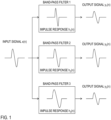
- Fig. 1 schematically illustrates a processing flow of the filter bank.
- a filter bank that applies three band-pass filters 1-3 to an input signal x(n) is considered. It is assumed that the filter bank is designed to match a specific input signal pattern to an impulse response of a specific band-pass filter.
- a waveform pattern of the input signal x(n) is substantially the same shape as an impulse response h 2 (n) of the band-pass filter 2, and it is expected that only an output signal y 2 (n) of the band-pass filter 2 takes a large output value in response to the waveform pattern of the input signal x(n) compared among the output of the band-pass filters 1-3.
- Patent literature 1 discloses an active noise control system including a speaker and one or more processors programmed to implement a delayless subband filtered-x least mean square control algorithm.
- the algorithm includes a variable bandwidth discrete Fourier transform filter bank having a number of subbands such that the system, in response to a broadband white noise reference signal indicative of road noise in the vehicle, exhibits a uniform gain spectrum across a frequency range defined by the subbands and partially cancels the road noise via output of the speaker.
- Patent literature 1 US Patent Application Laid-Open No. 2016/163305 A1 .
- Non-patent literature 1 M. Vetterli and C. Herley, "Wavelets and filter banks: theory and design,” in IEEE Transactions on Signal Processing, vol. 40, no. 9, pp. 2207-2232, Sep 1992 .
- An object of the present invention is to provide a signal feature extraction technique that can reduce leakage of an output signal to adjacent band-pass filters and in a time axis direction in filter bank analysis and flexibly cope with diversity of feature patterns of input signals to be analyzed.
- the present invention provides signal feature extraction apparatus and signal feature extraction methods, as well as corresponding programs, having the features of the respective independent claims. Preferred embodiments are described in the dependent claims.
- a signal feature extraction apparatus of a first example of the present invention is a signal feature extraction apparatus that extracts features of an input signal by filter bank analysis including a plurality of band-pass filters, assuming that M denotes a number of the band-pass filters, L denotes an integer which a maximum value of impulse response length of the band-pass filters is 2L+1, m denotes each integer from 1 or more to M or less, k denotes each integer from -2L or more to 2L or less, z k denotes a column vector having
- a signal feature extraction apparatus of a second example of the present invention is a signal feature extraction apparatus that extracts features of an input signal by filter bank analysis including a plurality of band-pass filters, assuming that a superscript H denotes transposition, M denotes a number of the band-pass filters, L denotes a value which a maximum value of impulse response length of the band-pass filters is 2L+1, m denotes each integer from 1 or more to M or less, k denotes each integer from -2L or more to 2L or less, z k denotes a column vector having
- the signal feature extraction technique of the invention it is possible to reduce leakage of an output signal between adjacent band-pass filters and in the time axis direction on filter bank analysis and flexibly cope with diversity of feature patterns of input signals to be analyzed.
- FIG. 2 A processing flow of a signal feature extraction method based on conventional filter bank analysis is shown in Fig. 2 .
- y m n h ⁇ m H x ⁇ n
- ⁇ H denotes transpose of a vector or matrix, and when its elements are complex numbers, it denotes conjugate transpose.
- the maximum value of impulse response length of each band-pass filter is assumed to be 2L+1.
- m it is any integer of 1 or more and M or less.
- M it is the total number of the band-pass filters.
- the impulse response length is different depending on the identification number m of band-pass filter, and some elements of an impulse response vector - h m related to a band-pass filter become 0 when impulse response length is less than 2L+1. In that case, multiply-add operation of the formula (1) of a part where an element is 0 can be omitted.
- Fig. 1 it is considered representing the input signal vector - x(n) by a linear combination of impulse response vectors - h 1 , - h 2 , and - h 3 of the respective filter banks. That is, it gives a relationship that satisfies a formula (2).
- H h ⁇ 1 h ⁇ 2 h ⁇ 3
- outputs of the conventional band-pass filters are represented by a formula (8), which is different from the formula (6).
- y 1 n y 2 n y 3 n H H x ⁇ n
- z k denotes a column vector having Ikl zeros as elements. It is assumed that these impulse response sequences are given as complex number sequences, sequences of real part and imaginary part can be mutually converted by Hilbert transformation or have an approximate equivalent relationship. It is considered extending the impulse response matrix H of the formula (3) to an extended impulse response matrix H e of (2L+1) ⁇ M(4L+1) shown in a formula (12) and obtain an output signal from an expansion coefficient vector y(n) satisfying a formula (13).
- ⁇ is a positive constant called a regularization parameter.
- the expansion coefficients for the input signal vector - x(n+1) which is shifted by one sample take a large value for the center impulse response vectors - h 1,1 , ..., - h m,1 , ..., - h M,1 that are actually not output, but take a small value for the center impulse response vectors - h 1,0 , ..., - h m,0 , ..., - h M,0 which are actually output, and therefore leakage to the time axis direction can be also prevented.
- a signal feature extraction apparatus 10 of a first embodiment includes a signal input part 1, an extended impulse response matrix generation part 2, an expansion coefficient calculation part 3, and a signal output part 4 as shown in Fig. 3 .
- the signal feature extraction apparatus 10 performs processing of steps shown in Fig. 4 and thereby implements a signal feature extraction method of the first embodiment.
- the signal feature extraction apparatus 10 is a special apparatus formed, for example, by causing a known or dedicated computer including a central processing unit (CPU), main storage device (RAM: Random Access Memory), and the like to read in a special program.
- the signal feature extraction apparatus 10 performs the processing, for example, under control of the central processing unit.
- Data input into the signal feature extraction apparatus 10 or data obtained by the processing is stored, for example, in the main storage device, and the data stored in the main storage device is read out on demand, and used for other processing.
- At least part of processing parts of the signal feature extraction apparatus 10 may be configured by hardware such as an integrated circuit.
- the generated input signal vector - x(n) is transmitted to the expansion coefficient calculation part 3.
- the generated extended impulse response matrix H e is transmitted to the expansion coefficient calculation part 3. Because the extended impulse response matrix H e can be reused for each time n, it may be configured to execute only the first time as shown in Fig. 4 .
- step S13 the expansion coefficient calculation part 3 receives the input signal vector - x(n) from the signal input part 1 and the extended impulse response matrix H e from the extended impulse response matrix generation part 2, and obtains an expansion coefficient vector ⁇ y(n) by the formula (14). The obtained expansion coefficient vector ⁇ y(n) is transmitted to the signal output part 4.
- the signal output part 4 receives the expansion coefficient vector ⁇ y(n) from the expansion coefficient calculation part 3 and outputs as an output signal at least one of expansion coefficients ⁇ y 1 (n), ..., ⁇ y m (n), ..., ⁇ y M (n) corresponding to center impulse response vectors - h 1,0 , ..., - h m,0 , ..., - h M,0 of the extended impulse response matrix H e of the expansion coefficient vector ⁇ y(n).
- step S15 it is determined whether there is an input signal x(n+1) at next time (n+1). If there is, 1 is added to a time index n in step S16, and the processing of steps S11 to S14 is performed again. If there is not, the processing is terminated.
- output signals may be generated by using an extended impulse response matrix H c which is formed by mainly extracting column vectors of interest in the analysis from the extended impulse response matrix H e . If the number of column vectors to be extracted is less than (2L+1), an expansion coefficient vector ⁇ y(n) for the extended impulse response matrix H c can be obtained as in a formula (15) by a least-squares method in the same manner as the formula (6).
- y ⁇ n H c H H c ⁇ 1 H c H x ⁇ n
- step S21 the signal input part 1 vectorizes an input signal x(n) to be analyzed and generates an input signal vector x(n) in the same manner as the first embodiment.
- the signal input part 1 may further apply filtering processing of removing components having a low correlation with the extended impulse response matrix H c to the input signal vector - x(n) to generate an input signal vector ⁇ x(n). It is optional whether the signal input part 1 performs step S22.
- the generated input signal vector - x(n) or - x(n) is transmitted to the expansion coefficient calculation part 3.
- the extended impulse response matrix generation part 2 generates an extended impulse response matrix H e in the same manner as the first embodiment. Furthermore, it generates an extended impulse response matrix H c by extracting column vectors of interest in analysis from the extended impulse response matrix H e . The column vectors to be extracted are predetermined. The generated extended impulse response matrix H c is transmitted to the expansion coefficient calculation part 3. Because the extended impulse response matrix H c can be reused for each time n, it may be configured to execute only the first time as shown in Fig. 5 .
- step S24 the expansion coefficient calculation part 3 receives the input signal vector - x(n) or - x(n) from the signal input part 1 and the extended impulse response matrix H c from the extended impulse response matrix generation part 2, and obtains an expansion coefficient vector ⁇ y(n) by the formula (15) when the input signal vector - x(n) is received and by the formula (16) when the input signal vector - x(n) is received.
- the obtained expansion coefficient vector ⁇ y(n) is transmitted to the signal output part 4.
- the signal output part 4 receives the expansion coefficient vector ⁇ y(n) from the expansion coefficient calculation part 3 and outputs as an output signal at least one of expansion coefficients corresponding to a center impulse response vector - h m,0 of the extended impulse response matrix H c of the expansion coefficient vector ⁇ y(n).
- step S26 it is determined whether there is an input signal x(n+1) at next time (n+1). If there is, 1 is added to a time index n in step S27, and then the processing of steps S21 to S25 is performed again. If there is not, the processing is terminated.
- a vector which is a complex conjugate of each column vector of the extended impulse response matrix H e or H c may be coupled with the extended impulse response matrix H e or H c , and then analyzed.
- a complex output signal it may be alright to take a form in which the complex output signal is decomposed into a real part and an imaginary part, or an amplitude component and a phase component, and at least one of them is output.
- H c H H c ⁇ 1 instead of the following inverse matrixes used in the formulas (15) and (16) in the second embodiment H c H H c ⁇ 1 , it may be calculated by using H c H H c + ⁇ I ⁇ 1 , where ⁇ is a positive actual number and I denotes a unit matrix.
- Points of the invention are summarized as follows.
- signal leakage may occur because there is redundancy between band-pass filters and in the time axis direction.
- a signal vector is represented by sparse expansion coefficients by over-complete base groups composed of impulse responses of band-pass filters.
- the sparse expansion coefficients are generally high in calculation cost in many cases, in the case where an influence of noise components of no interest in analysis can be excluded beforehand, filtering processing of removing the noise components is applied to the signal to be analyzed to narrow a feature space of the signal, and the expansion coefficients can be obtained under fewer base groups. If the number of base groups can be made smaller than the number of samples of the signal vector to be analyzed, a simple calculation algorithm such as a least-squares method can be applied.
- Input signals to be analyzed in the invention are biological signals (for example, an electrocardiogram (ECG, EKG), a pulse wave measured by photoplethysmogram (PPG) or the like, and a respiration curve) related to a physiological phenomenon having arbitrary periodicity including an acoustic signal or heartbeat, pulse, and breathing.
- the input signals to be analyzed repeat a local waveform pattern having substantially the same size and shape at almost periodic intervals.
- a plurality of waveform patterns like QRS wave and T wave in the electrocardiogram waveform appear or noise is mixed and observed.
- the invention contributes to the extraction of features of these signals by outputting large values (peak values) in synchronization with the appearance of a waveform pattern of interest in such signals.
- an object may be an electrocardiogram which is a method for measuring an electric activity associated with the heartbeat or it may be a seismocardiography (SCG) or ballistocardiography (BCG) which measures vibration of skin caused by the heartbeat with an accelerometer.
- SCG seismocardiography
- BCG ballistocardiography
- Biological signals not described above may also be included in the analysis objects as long as they have the above characteristics.
- the program describing the processing contents can be recorded on a computer-readable recording medium.
- the computer-readable recording medium may be any medium, for example, a magnetic recording device, an optical disc, a magneto-optical recording medium, and a semiconductor memory.
- Distribution of this program is carried out, for example, by selling, transferring, and renting a portable recording medium such as a DVD, CD-ROM, or a flash drive in which the program is recorded. Otherwise, the program can be pre-installed in arbitrary recording medium through the manufacturing process in a factory. Furthermore, the program may be stored in a storage device of a server computer, and the program may be distributed by transferring the program from the server computer to another computer via a network.
- a computer that executes such a program for example, stores the program recorded in the portable recording medium or the program transferred from the server computer in its own storage device.
- the computer reads the program stored in its own recording medium and executes the processing according to the read program.
- the computer may read the program directory from the portable recording medium and execute processing according to the program, or may sequentially execute, each time a program is transferred from the server computer to the computer, processing according to the received program.
- the above-described processing may be executed, not by transferring the program from the server computer to the computer, but by a configuration in which the above-described processing is executed by a so-called ASP (Application Service Provider) type service that achieves a processing function only by giving execution instructions and obtaining results.
- the program in this form includes information that is used for processing by an electronic computer and conforms to a program (data or the like that is not a direct instruction to a computer but has a characteristic defining processing of the computer).
- the apparatus is configured by executing a predetermined program on a computer, but at least part of the processing contents may be implemented by hardware.
Landscapes
- Engineering & Computer Science (AREA)
- Physics & Mathematics (AREA)
- Acoustics & Sound (AREA)
- Signal Processing (AREA)
- Multimedia (AREA)
- Human Computer Interaction (AREA)
- Audiology, Speech & Language Pathology (AREA)
- Health & Medical Sciences (AREA)
- Computational Linguistics (AREA)
- Theoretical Computer Science (AREA)
- Spectroscopy & Molecular Physics (AREA)
- Bioinformatics & Computational Biology (AREA)
- Computer Hardware Design (AREA)
- General Physics & Mathematics (AREA)
- Evolutionary Computation (AREA)
- Evolutionary Biology (AREA)
- Data Mining & Analysis (AREA)
- Life Sciences & Earth Sciences (AREA)
- Bioinformatics & Cheminformatics (AREA)
- Computer Vision & Pattern Recognition (AREA)
- Artificial Intelligence (AREA)
- General Engineering & Computer Science (AREA)
- Mathematical Physics (AREA)
- Complex Calculations (AREA)
- Filters That Use Time-Delay Elements (AREA)
- Noise Elimination (AREA)
Claims (7)
- Appareil d'extraction de caractéristiques de signal (10) pour extraire des caractéristiques d'un signal d'entrée par analyse de banc de filtres incluant une pluralité de filtres passe-bande,en supposant qu'un exposant H représente une transposition, λ est une constante positive, M représente un nombre des filtres passe-bande, L représente un entier dont une valeur maximale de longueur de réponse d'impulsion des filtres passe-bande est 2L+1, m représente chaque entier de 1 ou plus à M ou moins, k représente chaque entier de -2L ou plus à 2L ou moins, zk représente un vecteur de colonnes ayant |k| zéros en tant qu'éléments,
x (n) = [x(n + L), ... , x(n + 1),x(n),x(n - 1), ... , x(n - L)] H représente un vecteur de signal d'entrée ayant une séquence de signaux d'entrée à un temps n en tant qu'éléments, eth m = [hm (-L), ... , hm (-1),hm (0),hm (+1), ... , hm (L)] H représente un vecteur de réponse d'impulsion ayant une séquence de réponses d'impulsion d'un m-ième filtre passe-bande en tant qu'éléments,l'appareil d'extraction de caractéristiques de signal (10) comprenant :une partie de génération de matrice de réponse d'impulsion étendue (2) qui génère une matrice de réponse d'impulsion étendue He exprimée par une formule suivante : en utilisant une séquence de réponses d'impulsion
h m,k qui estlorsque k<0, et lorsque k≥0,
 une partie de calcul de coefficient d'expansion (3) qui obtient un vecteur de coefficient d'expansion ŷ(n) par le calcul d'une formule suivante :
 en utilisant le vecteur de signal d'entrée
x (n) et la matrice de réponse d'impulsion étendue He, où ŷ(n) satisfaitx (n) = Hey (n) ; etune partie de sortie de signal (4) qui délivre, en tant qu'un signal de sortie, au moins l'un de coefficients d'expansion correspondant à un vecteur de réponse d'impulsion centraleh m,0 de la matrice de réponse d'impulsion étendue He du vecteur de coefficient d'expansion ŷ(n). - Appareil d'extraction de caractéristiques de signal (10) pour extraire des caractéristiques d'un signal d'entrée par analyse de banc de filtres incluant une pluralité de filtres passe-bande,en supposant qu'un exposant H représente une transposition, M représente un nombre des filtres passe-bande, L représente une valeur dont une valeur maximale de longueur de réponse d'impulsion des filtres passe-bande est 2L+1, m représente chaque entier de 1 ou plus à M ou moins, k représente chaque entier de - 2L ou plus à 2L ou moins, zk représente un vecteur de colonnes ayant |k| zéros en tant qu'éléments,
x (n) = [x(n + L), ... , x(n + 1),x(n),x(n - 1), ... , x(n - L)] H représente un vecteur de signal d'entrée ayant une séquence de signaux d'entrée à un temps n en tant qu'éléments, eth m = [hm (-L), ... , hm(-1),hm (0),hm (+1), ... , hm (L)] H représente un vecteur de réponse d'impulsion ayant une séquence de réponses d'impulsion d'un m-ième filtre passe-bande en tant qu'éléments,l'appareil d'extraction de caractéristiques de signal (10) comprenant :une partie de génération de matrice de réponse d'impulsion étendue (2) qui génère une matrice de réponse d'impulsion étendue Hc par l'extraction de vecteurs de colonnes prédéterminés d'une matrice de réponse d'impulsion étendue He exprimée par une formule suivante : générée en utilisant une séquence de réponses d'impulsion
h m,k qui estlorsque k<0, et lorsque k≥0,
 une partie de calcul de coefficient d'expansion (3) qui obtient un vecteur de coefficient d'expansion ŷ(n) par le calcul d'une formule suivante :
 en utilisant le vecteur de signal d'entrée
x (n) et la matrice de réponse d'impulsion étendue Hc ; etune partie de sortie de signal (4) qui délivre, en tant qu'un signal de sortie, au moins l'un de coefficients d'expansion correspondant à un vecteur de réponse d'impulsion centraleh m,0 de la matrice de réponse d'impulsion étendue Hc du vecteur de coefficient d'expansion ŷ(n). - Appareil d'extraction de caractéristiques de signal (10) selon la revendication 2, comprenant en outre :une partie d'entrée de signal (1) qui génère un vecteur de signal d'entrée x̃(n) dans lequel des composantes ayant une basse corrélation avec la matrice de réponse d'impulsion étendue Hc sont supprimées du vecteur de signal d'entrée
x (n), dans lequella partie de calcul de coefficient d'expansion (3) obtient le vecteur de coefficient d'expansion ŷ(n) par le calcul d'une formule suivante : en utilisant le vecteur de signal d'entrée x̃(n) et la matrice de réponse d'impulsion étendue Hc.
 - Procédé d'extraction de caractéristiques de signal pour extraire des caractéristiques d'un signal d'entrée par analyse de banc de filtres incluant une pluralité de filtres passe-bande,en supposant qu'un exposant H représente une transposition, λ est une constante positive, M représente un nombre des filtres passe-bande, L représente un entier dont une valeur maximale de longueur de réponse d'impulsion des filtres passe-bande est 2L+1, m représente chaque entier de 1 ou plus à M ou moins, k représente chaque entier de -2L ou plus à 2L ou moins, zk représente un vecteur de colonnes ayant |k| zéros en tant qu'éléments,
x (n) = [x(n + L), ... , x(n + 1),x(n),x(n - 1), ... , x(n - L)] H représente un vecteur de signal d'entrée ayant une séquence de signaux d'entrée à un temps n en tant qu'éléments, eth m = [hm (-L), ... , hm (-1),hm (0),hm (+1), ... , hm (L)] H représente un vecteur de réponse d'impulsion ayant une séquence de réponses d'impulsion d'un m-ième filtre passe-bande en tant qu'éléments,le procédé d'extraction de caractéristiques de signal comprenant :une étape de génération de matrice de réponse d'impulsion étendue à laquelle une partie de génération de matrice de réponse d'impulsion étendue génère une matrice de réponse d'impulsion étendue He exprimée par une formule suivante : en utilisant une séquence de réponses d'impulsion
h m,k qui estlorsque k<0, et lorsque k≥0,
 une étape de calcul de coefficient d'expansion à laquelle une partie de calcul de coefficient d'expansion obtient un vecteur de coefficient d'expansion ŷ(n) par le calcul d'une formule suivante :
 en utilisant le vecteur de signal d'entrée
x (n) et la matrice de réponse d'impulsion étendue He, oùy (n) satisfaitx (n) = Hey (n) ; etune étape de sortie de signal à laquelle une partie de sortie de signal délivre, en tant qu'un signal de sortie, au moins l'un de coefficients d'expansion correspondant à un vecteur de réponse d'impulsion centraleh m,0 de la matrice de réponse d'impulsion étendue He du vecteur de coefficient d'expansion ŷ(n). - Procédé d'extraction de caractéristiques de signal pour extraire des caractéristiques d'un signal d'entrée par analyse de banc de filtres incluant une pluralité de filtres passe-bande,en supposant qu'un exposant H représente une transposition, M représente un nombre des filtres passe-bande, L représente une valeur dont une valeur maximale de longueur de réponse d'impulsion des filtres passe-bande est 2L+1, m représente chaque entier de 1 ou plus à M ou moins, k représente chaque entier de - 2L ou plus à 2L ou moins, zk représente un vecteur de colonnes ayant |k| zéros en tant qu'éléments,
x (n) = [x(n + L), ... , x(n + 1),x(n),x(n - 1), ... , x(n - L)] H représente un vecteur de signal d'entrée ayant une séquence de signaux d'entrée à un temps n en tant qu'éléments, eth m = [hm (-L), ... , hm (-1),hm (0),hm (+1), ... , hm (L)] H représente un vecteur de réponse d'impulsion ayant une séquence de réponses d'impulsion d'un m-ième filtre passe-bande en tant qu'éléments,le procédé d'extraction de caractéristiques de signal comprenant :une étape de génération de matrice de réponse d'impulsion étendue à laquelle une partie de génération de matrice de réponse d'impulsion étendue génère une matrice de réponse d'impulsion étendue Hc par l'extraction de vecteurs de colonnes prédéterminés d'une matrice de réponse d'impulsion étendue He exprimée par une formule suivante : générée en utilisant une séquence de réponses d'impulsion
h m,k qui estlorsque k<0, et lorsque k≥0,
 une étape de calcul de coefficient d'expansion à laquelle une partie de calcul de coefficient d'expansion obtient un vecteur de coefficient d'expansion ŷ(n) par le calcul d'une formule suivante :
 en utilisant le vecteur de signal d'entrée
x (n) et la matrice de réponse d'impulsion étendue Hc ; etune étape de sortie de signal à laquelle une partie de sortie de signal délivre, en tant qu'un signal de sortie, au moins l'un de coefficients d'expansion correspondant à un vecteur de réponse d'impulsion centraleh m,0 de la matrice de réponse d'impulsion étendue Hc du vecteur de coefficient d'expansion ŷ(n). - Procédé d'extraction de caractéristiques de signal selon la revendication 5, comprenant en outre :une étape d'entrée de signal à laquelle une partie d'entrée de signal génère un vecteur de signal d'entrée x̃(n) dans lequel des composantes ayant une basse corrélation avec la matrice de réponse d'impulsion étendue Hc sont supprimées du vecteur de signal d'entrée
x (n), dans lequell'étape de calcul de coefficient d'expansion obtient le vecteur de coefficient d'expansion ŷ(n) par le calcul d'une formule suivante : en utilisant le vecteur de signal d'entrée x̃(n) et la matrice de réponse d'impulsion étendue Hc.
 - Programme pour amener un ordinateur à fonctionner en tant que l'appareil d'extraction de caractéristiques de signal selon l'une quelconque des revendications 1 à 3.
Applications Claiming Priority (2)
| Application Number | Priority Date | Filing Date | Title |
|---|---|---|---|
| JP2016236591 | 2016-12-06 | ||
| PCT/JP2017/043656 WO2018105614A1 (fr) | 2016-12-06 | 2017-12-05 | Dispositif d'extraction de caractéristique de signal, procédé d'extraction de caractéristique de signal et programme |
Publications (3)
| Publication Number | Publication Date |
|---|---|
| EP3553950A1 EP3553950A1 (fr) | 2019-10-16 |
| EP3553950A4 EP3553950A4 (fr) | 2020-07-22 |
| EP3553950B1 true EP3553950B1 (fr) | 2023-10-11 |
Family
ID=62491061
Family Applications (1)
| Application Number | Title | Priority Date | Filing Date |
|---|---|---|---|
| EP17877712.4A Active EP3553950B1 (fr) | 2016-12-06 | 2017-12-05 | Dispositif d'extraction de caractéristique de signal, procédé d'extraction de caractéristique de signal et programme |
Country Status (6)
| Country | Link |
|---|---|
| US (1) | US10607631B2 (fr) |
| EP (1) | EP3553950B1 (fr) |
| JP (1) | JP6804554B2 (fr) |
| AU (1) | AU2017373523B2 (fr) |
| ES (1) | ES2964982T3 (fr) |
| WO (1) | WO2018105614A1 (fr) |
Family Cites Families (9)
| Publication number | Priority date | Publication date | Assignee | Title |
|---|---|---|---|---|
| JP3584458B2 (ja) * | 1997-10-31 | 2004-11-04 | ソニー株式会社 | パターン認識装置およびパターン認識方法 |
| US6308155B1 (en) * | 1999-01-20 | 2001-10-23 | International Computer Science Institute | Feature extraction for automatic speech recognition |
| JP4529492B2 (ja) * | 2004-03-11 | 2010-08-25 | 株式会社デンソー | 音声抽出方法、音声抽出装置、音声認識装置、及び、プログラム |
| JP2007054471A (ja) * | 2005-08-26 | 2007-03-08 | Nippon Koden Corp | 脈拍数測定装置及び脈拍数測定方法 |
| JP5085700B2 (ja) * | 2010-08-30 | 2012-11-28 | 株式会社東芝 | 音声合成装置、音声合成方法およびプログラム |
| JP2013113866A (ja) * | 2011-11-25 | 2013-06-10 | Nippon Telegr & Teleph Corp <Ntt> | 残響除去方法、残響除去装置、プログラム |
| JP2015509443A (ja) * | 2012-03-09 | 2015-03-30 | セノ メディカル インストルメンツ,インク. | 光音響イメージングシステムにおける統計マッピング |
| US9837065B2 (en) * | 2014-12-08 | 2017-12-05 | Ford Global Technologies, Llc | Variable bandwidth delayless subband algorithm for broadband active noise control system |
| US10090005B2 (en) * | 2016-03-10 | 2018-10-02 | Aspinity, Inc. | Analog voice activity detection |
-
2017
- 2017-12-05 US US16/464,751 patent/US10607631B2/en active Active
- 2017-12-05 EP EP17877712.4A patent/EP3553950B1/fr active Active
- 2017-12-05 ES ES17877712T patent/ES2964982T3/es active Active
- 2017-12-05 AU AU2017373523A patent/AU2017373523B2/en active Active
- 2017-12-05 JP JP2018555017A patent/JP6804554B2/ja active Active
- 2017-12-05 WO PCT/JP2017/043656 patent/WO2018105614A1/fr not_active Ceased
Also Published As
| Publication number | Publication date |
|---|---|
| WO2018105614A1 (fr) | 2018-06-14 |
| EP3553950A1 (fr) | 2019-10-16 |
| US10607631B2 (en) | 2020-03-31 |
| ES2964982T3 (es) | 2024-04-10 |
| AU2017373523A1 (en) | 2019-06-13 |
| JP6804554B2 (ja) | 2020-12-23 |
| JPWO2018105614A1 (ja) | 2019-10-24 |
| EP3553950A4 (fr) | 2020-07-22 |
| AU2017373523B2 (en) | 2020-09-24 |
| US20190385631A1 (en) | 2019-12-19 |
Similar Documents
| Publication | Publication Date | Title |
|---|---|---|
| Aqil et al. | ECG Signal Denoising by Discrete Wavelet Transform. | |
| Hlawatsch et al. | Time-frequency formulation, design, and implementation of time-varying optimal filters for signal estimation | |
| Selesnick | Least squares with examples in signal processing | |
| US7099417B2 (en) | Trace video filtering using wavelet de-noising techniques | |
| US20190000336A1 (en) | Detecting and predicting an epileptic seizure | |
| Harris et al. | Subspace detectors: Efficient implementation | |
| EP3553780A1 (fr) | Dispositif d'extraction de caractéristique de signal, procédé d'extraction de caractéristique de signal, et programme | |
| Alp et al. | Time–frequency analysis of signals using support adaptive Hermite–Gaussian expansions | |
| Ball et al. | PWC‐ICA: a method for stationary ordered blind source separation with application to EEG | |
| Oh et al. | Signal reconstruction from nonuniformly spaced samples using evolutionary Slepian transform-based POCS | |
| Lu et al. | A method combining fractal analysis and single channel ICA for vibration noise reduction | |
| Ochab et al. | On the pros and cons of using temporal derivatives to assess brain functional connectivity | |
| US10607631B2 (en) | Signal feature extraction apparatus, signal feature extraction method, and program | |
| CN111353415B (zh) | 一种脉冲响应中谐波成分的检测方法 | |
| CN107481732A (zh) | 一种口语测评中的降噪方法、装置及终端设备 | |
| Faghiri et al. | Single sideband modulation as a tool to improve functional connectivity estimation | |
| De Beer et al. | Absolute metabolite quantification by in vivo NMR spectroscopy: V. Multicentre quantitative data analysis trial on the overlapping background problem | |
| Zhang et al. | Frequency-response masking based filter bank for QRS dection in wearable biomedical devices | |
| Kodituwakku et al. | Radial function based kernel design for time-frequency distributions | |
| CN115441852A (zh) | 一种时间-顶点联合临界采样图滤波器组的设计方法 | |
| Agrawal et al. | Design of alias-free linear phase quadrature mirror filter banks using Eigen value-Eigen vector approach | |
| Ghosh et al. | Suitability of Advanced Non-Parameterized Time-Frequency Techniques for Condition Monitoring Applications | |
| Allen et al. | Analysis and application of digital spectral warping in analog and mixed-signal testing | |
| Ferdous et al. | Eyeblink artifact suppression from eeg signal using lifting wavelet transform | |
| CN121561255A (zh) | 基于多尺度频域子空间投影滤波的脑磁背景噪声抑制方法及装置 |
Legal Events
| Date | Code | Title | Description |
|---|---|---|---|
| STAA | Information on the status of an ep patent application or granted ep patent |
Free format text: STATUS: THE INTERNATIONAL PUBLICATION HAS BEEN MADE |
|
| PUAI | Public reference made under article 153(3) epc to a published international application that has entered the european phase |
Free format text: ORIGINAL CODE: 0009012 |
|
| STAA | Information on the status of an ep patent application or granted ep patent |
Free format text: STATUS: REQUEST FOR EXAMINATION WAS MADE |
|
| 17P | Request for examination filed |
Effective date: 20190708 |
|
| AK | Designated contracting states |
Kind code of ref document: A1 Designated state(s): AL AT BE BG CH CY CZ DE DK EE ES FI FR GB GR HR HU IE IS IT LI LT LU LV MC MK MT NL NO PL PT RO RS SE SI SK SM TR |
|
| AX | Request for extension of the european patent |
Extension state: BA ME |
|
| DAV | Request for validation of the european patent (deleted) | ||
| DAX | Request for extension of the european patent (deleted) | ||
| A4 | Supplementary search report drawn up and despatched |
Effective date: 20200619 |
|
| RIC1 | Information provided on ipc code assigned before grant |
Ipc: H03H 17/02 20060101AFI20200615BHEP Ipc: G06K 9/00 20060101ALI20200615BHEP Ipc: A61B 5/0452 20060101ALI20200615BHEP |
|
| GRAP | Despatch of communication of intention to grant a patent |
Free format text: ORIGINAL CODE: EPIDOSNIGR1 |
|
| STAA | Information on the status of an ep patent application or granted ep patent |
Free format text: STATUS: GRANT OF PATENT IS INTENDED |
|
| RIC1 | Information provided on ipc code assigned before grant |
Ipc: A61B 5/349 20210101ALI20230418BHEP Ipc: G06F 18/00 20230101ALI20230418BHEP Ipc: H03H 17/02 20060101AFI20230418BHEP |
|
| INTG | Intention to grant announced |
Effective date: 20230509 |
|
| GRAS | Grant fee paid |
Free format text: ORIGINAL CODE: EPIDOSNIGR3 |
|
| GRAA | (expected) grant |
Free format text: ORIGINAL CODE: 0009210 |
|
| STAA | Information on the status of an ep patent application or granted ep patent |
Free format text: STATUS: THE PATENT HAS BEEN GRANTED |
|
| AK | Designated contracting states |
Kind code of ref document: B1 Designated state(s): AL AT BE BG CH CY CZ DE DK EE ES FI FR GB GR HR HU IE IS IT LI LT LU LV MC MK MT NL NO PL PT RO RS SE SI SK SM TR |
|
| REG | Reference to a national code |
Ref country code: GB Ref legal event code: FG4D |
|
| REG | Reference to a national code |
Ref country code: CH Ref legal event code: EP |
|
| REG | Reference to a national code |
Ref country code: DE Ref legal event code: R096 Ref document number: 602017075321 Country of ref document: DE |
|
| REG | Reference to a national code |
Ref country code: IE Ref legal event code: FG4D |
|
| REG | Reference to a national code |
Ref country code: LT Ref legal event code: MG9D |
|
| REG | Reference to a national code |
Ref country code: NL Ref legal event code: MP Effective date: 20231011 |
|
| REG | Reference to a national code |
Ref country code: AT Ref legal event code: MK05 Ref document number: 1621243 Country of ref document: AT Kind code of ref document: T Effective date: 20231011 |
|
| PG25 | Lapsed in a contracting state [announced via postgrant information from national office to epo] |
Ref country code: NL Free format text: LAPSE BECAUSE OF FAILURE TO SUBMIT A TRANSLATION OF THE DESCRIPTION OR TO PAY THE FEE WITHIN THE PRESCRIBED TIME-LIMIT Effective date: 20231011 |
|
| PG25 | Lapsed in a contracting state [announced via postgrant information from national office to epo] |
Ref country code: GR Free format text: LAPSE BECAUSE OF FAILURE TO SUBMIT A TRANSLATION OF THE DESCRIPTION OR TO PAY THE FEE WITHIN THE PRESCRIBED TIME-LIMIT Effective date: 20240112 |
|
| PG25 | Lapsed in a contracting state [announced via postgrant information from national office to epo] |
Ref country code: IS Free format text: LAPSE BECAUSE OF FAILURE TO SUBMIT A TRANSLATION OF THE DESCRIPTION OR TO PAY THE FEE WITHIN THE PRESCRIBED TIME-LIMIT Effective date: 20240211 |
|
| REG | Reference to a national code |
Ref country code: ES Ref legal event code: FG2A Ref document number: 2964982 Country of ref document: ES Kind code of ref document: T3 Effective date: 20240410 |
|
| PG25 | Lapsed in a contracting state [announced via postgrant information from national office to epo] |
Ref country code: LT Free format text: LAPSE BECAUSE OF FAILURE TO SUBMIT A TRANSLATION OF THE DESCRIPTION OR TO PAY THE FEE WITHIN THE PRESCRIBED TIME-LIMIT Effective date: 20231011 |
|
| PG25 | Lapsed in a contracting state [announced via postgrant information from national office to epo] |
Ref country code: AT Free format text: LAPSE BECAUSE OF FAILURE TO SUBMIT A TRANSLATION OF THE DESCRIPTION OR TO PAY THE FEE WITHIN THE PRESCRIBED TIME-LIMIT Effective date: 20231011 |
|
| PG25 | Lapsed in a contracting state [announced via postgrant information from national office to epo] |
Ref country code: LT Free format text: LAPSE BECAUSE OF FAILURE TO SUBMIT A TRANSLATION OF THE DESCRIPTION OR TO PAY THE FEE WITHIN THE PRESCRIBED TIME-LIMIT Effective date: 20231011 Ref country code: IS Free format text: LAPSE BECAUSE OF FAILURE TO SUBMIT A TRANSLATION OF THE DESCRIPTION OR TO PAY THE FEE WITHIN THE PRESCRIBED TIME-LIMIT Effective date: 20240211 Ref country code: GR Free format text: LAPSE BECAUSE OF FAILURE TO SUBMIT A TRANSLATION OF THE DESCRIPTION OR TO PAY THE FEE WITHIN THE PRESCRIBED TIME-LIMIT Effective date: 20240112 Ref country code: BG Free format text: LAPSE BECAUSE OF FAILURE TO SUBMIT A TRANSLATION OF THE DESCRIPTION OR TO PAY THE FEE WITHIN THE PRESCRIBED TIME-LIMIT Effective date: 20240111 Ref country code: AT Free format text: LAPSE BECAUSE OF FAILURE TO SUBMIT A TRANSLATION OF THE DESCRIPTION OR TO PAY THE FEE WITHIN THE PRESCRIBED TIME-LIMIT Effective date: 20231011 Ref country code: PT Free format text: LAPSE BECAUSE OF FAILURE TO SUBMIT A TRANSLATION OF THE DESCRIPTION OR TO PAY THE FEE WITHIN THE PRESCRIBED TIME-LIMIT Effective date: 20240212 |
|
| PG25 | Lapsed in a contracting state [announced via postgrant information from national office to epo] |
Ref country code: SE Free format text: LAPSE BECAUSE OF FAILURE TO SUBMIT A TRANSLATION OF THE DESCRIPTION OR TO PAY THE FEE WITHIN THE PRESCRIBED TIME-LIMIT Effective date: 20231011 Ref country code: RS Free format text: LAPSE BECAUSE OF FAILURE TO SUBMIT A TRANSLATION OF THE DESCRIPTION OR TO PAY THE FEE WITHIN THE PRESCRIBED TIME-LIMIT Effective date: 20231011 Ref country code: PL Free format text: LAPSE BECAUSE OF FAILURE TO SUBMIT A TRANSLATION OF THE DESCRIPTION OR TO PAY THE FEE WITHIN THE PRESCRIBED TIME-LIMIT Effective date: 20231011 Ref country code: NO Free format text: LAPSE BECAUSE OF FAILURE TO SUBMIT A TRANSLATION OF THE DESCRIPTION OR TO PAY THE FEE WITHIN THE PRESCRIBED TIME-LIMIT Effective date: 20240111 Ref country code: LV Free format text: LAPSE BECAUSE OF FAILURE TO SUBMIT A TRANSLATION OF THE DESCRIPTION OR TO PAY THE FEE WITHIN THE PRESCRIBED TIME-LIMIT Effective date: 20231011 Ref country code: HR Free format text: LAPSE BECAUSE OF FAILURE TO SUBMIT A TRANSLATION OF THE DESCRIPTION OR TO PAY THE FEE WITHIN THE PRESCRIBED TIME-LIMIT Effective date: 20231011 |
|
| PG25 | Lapsed in a contracting state [announced via postgrant information from national office to epo] |
Ref country code: DK Free format text: LAPSE BECAUSE OF FAILURE TO SUBMIT A TRANSLATION OF THE DESCRIPTION OR TO PAY THE FEE WITHIN THE PRESCRIBED TIME-LIMIT Effective date: 20231011 |
|
| REG | Reference to a national code |
Ref country code: DE Ref legal event code: R097 Ref document number: 602017075321 Country of ref document: DE |
|
| PG25 | Lapsed in a contracting state [announced via postgrant information from national office to epo] |
Ref country code: CZ Free format text: LAPSE BECAUSE OF FAILURE TO SUBMIT A TRANSLATION OF THE DESCRIPTION OR TO PAY THE FEE WITHIN THE PRESCRIBED TIME-LIMIT Effective date: 20231011 |
|
| PG25 | Lapsed in a contracting state [announced via postgrant information from national office to epo] |
Ref country code: SK Free format text: LAPSE BECAUSE OF FAILURE TO SUBMIT A TRANSLATION OF THE DESCRIPTION OR TO PAY THE FEE WITHIN THE PRESCRIBED TIME-LIMIT Effective date: 20231011 |
|
| PG25 | Lapsed in a contracting state [announced via postgrant information from national office to epo] |
Ref country code: SM Free format text: LAPSE BECAUSE OF FAILURE TO SUBMIT A TRANSLATION OF THE DESCRIPTION OR TO PAY THE FEE WITHIN THE PRESCRIBED TIME-LIMIT Effective date: 20231011 Ref country code: SK Free format text: LAPSE BECAUSE OF FAILURE TO SUBMIT A TRANSLATION OF THE DESCRIPTION OR TO PAY THE FEE WITHIN THE PRESCRIBED TIME-LIMIT Effective date: 20231011 Ref country code: RO Free format text: LAPSE BECAUSE OF FAILURE TO SUBMIT A TRANSLATION OF THE DESCRIPTION OR TO PAY THE FEE WITHIN THE PRESCRIBED TIME-LIMIT Effective date: 20231011 Ref country code: EE Free format text: LAPSE BECAUSE OF FAILURE TO SUBMIT A TRANSLATION OF THE DESCRIPTION OR TO PAY THE FEE WITHIN THE PRESCRIBED TIME-LIMIT Effective date: 20231011 Ref country code: DK Free format text: LAPSE BECAUSE OF FAILURE TO SUBMIT A TRANSLATION OF THE DESCRIPTION OR TO PAY THE FEE WITHIN THE PRESCRIBED TIME-LIMIT Effective date: 20231011 Ref country code: CZ Free format text: LAPSE BECAUSE OF FAILURE TO SUBMIT A TRANSLATION OF THE DESCRIPTION OR TO PAY THE FEE WITHIN THE PRESCRIBED TIME-LIMIT Effective date: 20231011 |
|
| REG | Reference to a national code |
Ref country code: CH Ref legal event code: PL |
|
| PLBE | No opposition filed within time limit |
Free format text: ORIGINAL CODE: 0009261 |
|
| STAA | Information on the status of an ep patent application or granted ep patent |
Free format text: STATUS: NO OPPOSITION FILED WITHIN TIME LIMIT |
|
| PG25 | Lapsed in a contracting state [announced via postgrant information from national office to epo] |
Ref country code: LU Free format text: LAPSE BECAUSE OF NON-PAYMENT OF DUE FEES Effective date: 20231205 |
|
| PG25 | Lapsed in a contracting state [announced via postgrant information from national office to epo] |
Ref country code: MC Free format text: LAPSE BECAUSE OF FAILURE TO SUBMIT A TRANSLATION OF THE DESCRIPTION OR TO PAY THE FEE WITHIN THE PRESCRIBED TIME-LIMIT Effective date: 20231011 |
|
| REG | Reference to a national code |
Ref country code: BE Ref legal event code: MM Effective date: 20231231 |
|
| PG25 | Lapsed in a contracting state [announced via postgrant information from national office to epo] |
Ref country code: MC Free format text: LAPSE BECAUSE OF FAILURE TO SUBMIT A TRANSLATION OF THE DESCRIPTION OR TO PAY THE FEE WITHIN THE PRESCRIBED TIME-LIMIT Effective date: 20231011 Ref country code: LU Free format text: LAPSE BECAUSE OF NON-PAYMENT OF DUE FEES Effective date: 20231205 |
|
| 26N | No opposition filed |
Effective date: 20240712 |
|
| REG | Reference to a national code |
Ref country code: IE Ref legal event code: MM4A |
|
| PG25 | Lapsed in a contracting state [announced via postgrant information from national office to epo] |
Ref country code: IE Free format text: LAPSE BECAUSE OF NON-PAYMENT OF DUE FEES Effective date: 20231205 |
|
| PG25 | Lapsed in a contracting state [announced via postgrant information from national office to epo] |
Ref country code: BE Free format text: LAPSE BECAUSE OF NON-PAYMENT OF DUE FEES Effective date: 20231231 |
|
| PG25 | Lapsed in a contracting state [announced via postgrant information from national office to epo] |
Ref country code: CH Free format text: LAPSE BECAUSE OF NON-PAYMENT OF DUE FEES Effective date: 20231231 |
|
| PG25 | Lapsed in a contracting state [announced via postgrant information from national office to epo] |
Ref country code: SI Free format text: LAPSE BECAUSE OF FAILURE TO SUBMIT A TRANSLATION OF THE DESCRIPTION OR TO PAY THE FEE WITHIN THE PRESCRIBED TIME-LIMIT Effective date: 20231011 |
|
| PG25 | Lapsed in a contracting state [announced via postgrant information from national office to epo] |
Ref country code: SI Free format text: LAPSE BECAUSE OF FAILURE TO SUBMIT A TRANSLATION OF THE DESCRIPTION OR TO PAY THE FEE WITHIN THE PRESCRIBED TIME-LIMIT Effective date: 20231011 Ref country code: IE Free format text: LAPSE BECAUSE OF NON-PAYMENT OF DUE FEES Effective date: 20231205 Ref country code: CH Free format text: LAPSE BECAUSE OF NON-PAYMENT OF DUE FEES Effective date: 20231231 Ref country code: BE Free format text: LAPSE BECAUSE OF NON-PAYMENT OF DUE FEES Effective date: 20231231 |
|
| PG25 | Lapsed in a contracting state [announced via postgrant information from national office to epo] |
Ref country code: FI Free format text: LAPSE BECAUSE OF FAILURE TO SUBMIT A TRANSLATION OF THE DESCRIPTION OR TO PAY THE FEE WITHIN THE PRESCRIBED TIME-LIMIT Effective date: 20231011 |
|
| PG25 | Lapsed in a contracting state [announced via postgrant information from national office to epo] |
Ref country code: CY Free format text: LAPSE BECAUSE OF FAILURE TO SUBMIT A TRANSLATION OF THE DESCRIPTION OR TO PAY THE FEE WITHIN THE PRESCRIBED TIME-LIMIT; INVALID AB INITIO Effective date: 20171205 |
|
| PG25 | Lapsed in a contracting state [announced via postgrant information from national office to epo] |
Ref country code: HU Free format text: LAPSE BECAUSE OF FAILURE TO SUBMIT A TRANSLATION OF THE DESCRIPTION OR TO PAY THE FEE WITHIN THE PRESCRIBED TIME-LIMIT; INVALID AB INITIO Effective date: 20171205 |
|
| PG25 | Lapsed in a contracting state [announced via postgrant information from national office to epo] |
Ref country code: TR Free format text: LAPSE BECAUSE OF FAILURE TO SUBMIT A TRANSLATION OF THE DESCRIPTION OR TO PAY THE FEE WITHIN THE PRESCRIBED TIME-LIMIT Effective date: 20231011 |
|
| PGFP | Annual fee paid to national office [announced via postgrant information from national office to epo] |
Ref country code: DE Payment date: 20251211 Year of fee payment: 9 |
|
| PGFP | Annual fee paid to national office [announced via postgrant information from national office to epo] |
Ref country code: GB Payment date: 20251219 Year of fee payment: 9 |
|
| PGFP | Annual fee paid to national office [announced via postgrant information from national office to epo] |
Ref country code: IT Payment date: 20251223 Year of fee payment: 9 |
|
| PGFP | Annual fee paid to national office [announced via postgrant information from national office to epo] |
Ref country code: FR Payment date: 20251229 Year of fee payment: 9 |
|
| REG | Reference to a national code |
Ref country code: DE Ref legal event code: R081 Ref document number: 602017075321 Country of ref document: DE Owner name: NTT, INC., JP Free format text: FORMER OWNER: NIPPON TELEGRAPH AND TELEPHONE CORPORATION, TOKYO, JP Ref country code: DE Ref legal event code: R082 Ref document number: 602017075321 Country of ref document: DE Representative=s name: DENNEMEYER & ASSOCIATES RECHTSANWALTSGESELLSCH, DE |
|
| PGFP | Annual fee paid to national office [announced via postgrant information from national office to epo] |
Ref country code: ES Payment date: 20260130 Year of fee payment: 9 |