EP3553938A1 - Multi-spoke-type ultrasonic motor - Google Patents
Multi-spoke-type ultrasonic motor Download PDFInfo
- Publication number
- EP3553938A1 EP3553938A1 EP17898309.4A EP17898309A EP3553938A1 EP 3553938 A1 EP3553938 A1 EP 3553938A1 EP 17898309 A EP17898309 A EP 17898309A EP 3553938 A1 EP3553938 A1 EP 3553938A1
- Authority
- EP
- European Patent Office
- Prior art keywords
- stator
- spoke
- teeth
- ultrasonic motor
- rotor
- Prior art date
- Legal status (The legal status is an assumption and is not a legal conclusion. Google has not performed a legal analysis and makes no representation as to the accuracy of the status listed.)
- Granted
Links
Images

Classifications
-
- H—ELECTRICITY
- H02—GENERATION; CONVERSION OR DISTRIBUTION OF ELECTRIC POWER
- H02N—ELECTRIC MACHINES NOT OTHERWISE PROVIDED FOR
- H02N2/00—Electric machines in general using piezoelectric effect, electrostriction or magnetostriction
- H02N2/10—Electric machines in general using piezoelectric effect, electrostriction or magnetostriction producing rotary motion, e.g. rotary motors
- H02N2/12—Constructional details
-
- H—ELECTRICITY
- H02—GENERATION; CONVERSION OR DISTRIBUTION OF ELECTRIC POWER
- H02N—ELECTRIC MACHINES NOT OTHERWISE PROVIDED FOR
- H02N2/00—Electric machines in general using piezoelectric effect, electrostriction or magnetostriction
- H02N2/10—Electric machines in general using piezoelectric effect, electrostriction or magnetostriction producing rotary motion, e.g. rotary motors
- H02N2/16—Electric machines in general using piezoelectric effect, electrostriction or magnetostriction producing rotary motion, e.g. rotary motors using travelling waves, i.e. Rayleigh surface waves
- H02N2/163—Motors with ring stator
-
- H—ELECTRICITY
- H02—GENERATION; CONVERSION OR DISTRIBUTION OF ELECTRIC POWER
- H02N—ELECTRIC MACHINES NOT OTHERWISE PROVIDED FOR
- H02N2/00—Electric machines in general using piezoelectric effect, electrostriction or magnetostriction
- H02N2/0005—Electric machines in general using piezoelectric effect, electrostriction or magnetostriction producing non-specific motion; Details common to machines covered by H02N2/02 - H02N2/16
- H02N2/001—Driving devices, e.g. vibrators
- H02N2/002—Driving devices, e.g. vibrators using only longitudinal or radial modes
-
- H—ELECTRICITY
- H02—GENERATION; CONVERSION OR DISTRIBUTION OF ELECTRIC POWER
- H02N—ELECTRIC MACHINES NOT OTHERWISE PROVIDED FOR
- H02N2/00—Electric machines in general using piezoelectric effect, electrostriction or magnetostriction
- H02N2/0005—Electric machines in general using piezoelectric effect, electrostriction or magnetostriction producing non-specific motion; Details common to machines covered by H02N2/02 - H02N2/16
- H02N2/005—Mechanical details, e.g. housings
- H02N2/0065—Friction interface
-
- H—ELECTRICITY
- H02—GENERATION; CONVERSION OR DISTRIBUTION OF ELECTRIC POWER
- H02N—ELECTRIC MACHINES NOT OTHERWISE PROVIDED FOR
- H02N2/00—Electric machines in general using piezoelectric effect, electrostriction or magnetostriction
- H02N2/10—Electric machines in general using piezoelectric effect, electrostriction or magnetostriction producing rotary motion, e.g. rotary motors
- H02N2/103—Electric machines in general using piezoelectric effect, electrostriction or magnetostriction producing rotary motion, e.g. rotary motors by pressing one or more vibrators against the rotor
Definitions
- the present invention relates to the technical field of ultrasonic motors, and in particular, to a multi-spoke-type ultrasonic motor.
- a direct current motor As a drive motor, a direct current motor is widely used, but with the decrease of the size, the Joule heat loss of the motor is sharply increased, and the drive capability of the motor is significantly decreased.
- An ultrasonic motor transforms electric energy into mechanical energy by using the inverse piezoelectric effect and the friction effect of a material. With the decrease of the size, mechanical performance of the motor is sluggishly decreased, and this helps miniaturization and microminiaturization of the motor.
- Existing travelling-wave ultrasonic motors have excellent output performance, but with the decrease of the space size of the motor, machining precision requirements for parts are increased rapidly. Reducing the machining precision requirements for parts by structure designing is main work of a current ultrasonic motor in the miniaturization aspect.
- an internal ring provided with spatial rotational symmetrical teeth is used to form a stator, and in a work state of driving a hemispherical or tapered rotor by friction, the machining requirements for parts are reduced while the mechanical performance of the ultrasonic motor is increased.
- Embodiments of the present invention provide a multi-spoke-type ultrasonic motor, to increase output performance of the ultrasonic motor, prolong service life, and reduce manufacturing costs.
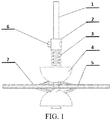
- An embodiment of the present invention provides a multi-spoke-type ultrasonic motor, including: a rotating shaft (1), a fastening sleeve (2), a spring (3), a rotor (4), a stator (5), a fastening screw (6), and piezoelectric ceramics (7), where the rotor (4), the stator (5), the spring (3), and the fastening sleeve (2) are sequentially connected by using the rotating shaft (1); the fastening screw (6) is located in the middle of a side surface of the fastening sleeve, and the fastening screw (6) is adjusted to make the fastening sleeve (2) slide on the rotating shaft (1), to adjust a pre-pressure of the spring (3); the spring (3) is between the fastening sleeve (2) and the rotor (4), and is pressed on a surface of the rotor (4); the rotor (4) is
- an angle between a central line of the internal spoke-like teeth of the stator (5) and a normal line of a contact position of a stator inner ring in which a tooth root is located is ⁇ , and ⁇ is designed based on requirement.
- the quantity of the internal spoke-like teeth of the stator (5) is designed based on a requirement, and the spoke-like teeth are rotationally symmetrical about a vertex being the circle center of the stator ring.
- angle ⁇ there is an angle ⁇ between the internal spoke-like teeth and a plane in which the stator (5) is located, and the angle ⁇ is greater than 0° and less than 90°.
- the angle ⁇ is formed by bending the internal spoke-like teeth of the stator upward and downward separately from the tooth root to make the internal spoke-like teeth away from a plane in which a ring of the stator (5) is located.
- an outer ring of the stator (5) is provided with several hole fixing structures (10), evenly distributed on the outer ring of the stator (5).
- the surface (9) of the stator (5) is polished.
- the rotor (4) is manufactured by using the wear-resistant material.
- the size of the inner diameter of the piezoelectric ceramic (7) is the same as the size of the outer ring surface of the stator (5), and both the upper sheet and the lower sheet of the piezoelectric ceramics are polarized along the direction of the thickness and have opposite polarization directions.
- the electrode when the motor is in a work state, applies the same electric excitation signal to the exposed part of the upper sheet and the lower sheet of the piezoelectric ceramics (7), and the electric excitation signal is a sinusoidal wave signal.
- the multi-spoke-type ultrasonic motor provided by the embodiments of the present invention has better performance at the output torque and the output rotating speed, a simple and compact structure, low machining precision dependence, a low drive voltage, a simple excitation manner, low manufacturing costs, and a stable and reliable output, and is suitable for large-scale industrial applications.
- the multi-spoke-type ultrasonic motor may be applied to a micro helicopter motor, and a zoom system of a micro electronic device, such as a capsule endoscope, an electronic eyeball, a digital single lens reflex, or a smartphone.
- the embodiments of the present invention have broad application prospects in scientific and technological fields of robotics, medical instruments, micromechanics, and aeronautics and astronautics.
- Embodiments of the present invention provide a multi-spoke-type ultrasonic motor, to increase output performance of the ultrasonic motor, prolong service life, and reduce manufacturing costs.
- an embodiment of the present invention provides a multi-spoke-type ultrasonic motor, including: a rotating shaft (1), a fastening sleeve (2), a spring (3), a rotor (4), a stator (5), a fastening screw (6), and piezoelectric ceramics (7), where the rotor (4), the stator (5), the spring (3), and the fastening sleeve (2) are sequentially connected by using the rotating shaft (1); the fastening screw (6) is located in the middle of a side surface of the fastening sleeve, and the fastening screw (6) is adjusted to make the fastening sleeve (2) slide on the rotating shaft (1), to adjust a pre-pressure of the spring (3); the spring (3) is between the fastening sleeve (2) and the rotor (4), and is pressed on a surface of the rotor (4)
- the quantity of the internal spoke-like teeth of the stator (5) is designed based on a requirement, and the spoke-like teeth are rotationally symmetrical about a vertex being the circle center of the stator ring.
- the size of the inner diameter of the piezoelectric ceramic (7) is the same as the size of the outer ring surface of the stator (5), and both the upper sheet and the lower sheet of the piezoelectric ceramics are polarized along the direction of the thickness and have opposite polarization directions.
- the upper sheet and the lower sheet of the piezoelectric ceramics (7) apply a same sinusoidal electric signal by using the electrode, to excite the stator to vibrate, and the spoke-like teeth of the stator drive the rotor to rotate.
- a first-order radial vibration mode of the motor stator (5) is used as the work mode.
- the internal spoke-like teeth of the stator (5) obtain a relatively large displacement, and the rotor (4) is driven by using the friction effect.
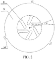
- position of contact between the rotor (4) and the stator (5) is on the internal spoke-like tooth surface (8) of the annular stator; and the angle between central line of the internal spoke-like teeth of the stator (5) and normal line of the contact position of the stator inner ring in which the tooth root is located is ⁇ , and ⁇ can be designed based on requirement.
- the quantity of the internal spoke-like teeth of the stator (5) is designed based on requirement, and the spoke-like teeth need to be symmetrical about the center.
- the quantity of the internal spoke-like teeth of the stator (5) is 6, evenly distributed at the stator inner ring, the spoke-like teeth (8) whose angle on a planar projection of the stator ring is 120° are a group, and there are a total of two groups.
- the internal spoke-like teeth of the stator (5) of the ultrasonic motor provided by this embodiment of the present invention may be in another quantity, but need to be ensured to be rotationally symmetrical about the center. As shown in FIG. 3 , the quantity of the internal spoke-like teeth of the stator is 3, and technical effects brought by different quantities of spoke-like teeth are also different. In this embodiment of the present invention, if there are three internal spoke-like teeth, the motor can obtain a relatively high output rotating speed; and if there are six internal spoke-like teeth, the motor can obtain relatively large output torque.
- the output rotating speed and torque of the motor may be controlled by changing value of ⁇ .
- the stator (5) is an annular metal sheet internally provided with spoke-like teeth, there is an angle ⁇ between the internal spoke-like teeth and a plane in which the stator (5) is located, and the angle ⁇ is greater than 0° and less than 90°.
- the angle ⁇ is greater than 0° and less than or equal to 45°.
- the quantity of the internal spoke-like teeth of the stator (5) is designed based on requirement, and the spoke-like teeth are rotationally symmetrical about a vertex being the circle center of the stator ring.
- the angle ⁇ is formed by bending the internal spoke-like teeth of the stator upward and downward separately from the tooth root to make the internal spoke-like teeth away from a plane in which a ring of the stator (5) is located.
- the design of the angle may fully use vibration energy of the stator, optimize contact between the stator and the rotor, and increase output torque and a rotating speed of the motor.
- the design of the angle has a spring effect, and the angle may replace a pre-pressure spring in a micro motor system, and reduce space.
- the design of the angle makes the motor rotor receive stable three-point support, to weaken shaking of the rotating shaft during rotating, and make the motor operate stably.
- a value ⁇ of the angle is: 0 ° ⁇ ⁇ ⁇ 90 ° .
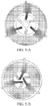
- FIG. 5-A which is a schematic diagram of an expansion mode when a work mode of a multi-spoke-type ultrasonic motor stator vibrates radially according to an embodiment of the present invention
- FIG. 5-B which is t a schematic diagram of a contraction mode when a work mode of a multi-spoke-type ultrasonic motor stator vibrates radially according to an embodiment of the present invention
- a very large radial displacement may be obtained by movement of the internal spoke-like teeth of the stator (5).
- the spoke-like teeth are optimized, and by changing its length, a first-order longitudinal vibration mode frequency of the spoke-like teeth is equal to a first-order radial vibration mode frequency of the stator.
- the outer ring of the stator (5) is provided with three square hole fixing structures (10), evenly distributed on the outer ring of the stator (5).
- the surface (9) of the stator (5) is polished.
- the surface (9) of the stator is polished.
- the rotor (4) is manufactured by using the wear-resistant material.
- the size of the inner diameter of the piezoelectric ceramic (7) is the same as the size of the outer ring surface of the stator (5), and both the upper sheet and the lower sheet of the piezoelectric ceramics are polarized along the direction of the thickness and have opposite polarization directions. Both an upper sheet and a lower sheet of the piezoelectric ceramics are polarized along the direction of the thickness and have opposite polarization directions, and this facilitates wiring. In this embodiment, only one channel of signal need to be used to complete electric excitation.
- the electrode when the motor is in a work state, applies a same electric excitation signal to the exposed part of the upper sheet and the lower sheet of the piezoelectric ceramics (7), and the electric excitation signal is a sinusoidal wave.
- the multi-spoke-type ultrasonic motor provided by the embodiments of the present invention has better performance at the output torque and the output rotating speed, a simple and compact structure, low machining precision dependence, a low drive voltage, a simple excitation manner, low manufacturing costs, and a stable and reliable output, and is suitable for large-scale industrial applications.
- the multi-spoke-type ultrasonic motor may be applied to a power plant of a micro aerial vehicle; a micro electronic and medical device such as a driver of a capsule endoscope; and a zoom system of a micro electronic device, such as a capsule endoscope, an electronic eyeball, a digital single lens reflex, or a lens of a smartphone.
- the embodiments of the present invention have broad application prospects in scientific and technological fields of robotics, medical instruments, micromechanics, and aeronautics and astronautics.
Landscapes
- General Electrical Machinery Utilizing Piezoelectricity, Electrostriction Or Magnetostriction (AREA)
Abstract
Description
- The present invention relates to the technical field of ultrasonic motors, and in particular, to a multi-spoke-type ultrasonic motor.
- As a drive motor, a direct current motor is widely used, but with the decrease of the size, the Joule heat loss of the motor is sharply increased, and the drive capability of the motor is significantly decreased. An ultrasonic motor transforms electric energy into mechanical energy by using the inverse piezoelectric effect and the friction effect of a material. With the decrease of the size, mechanical performance of the motor is sluggishly decreased, and this helps miniaturization and microminiaturization of the motor. Existing travelling-wave ultrasonic motors have excellent output performance, but with the decrease of the space size of the motor, machining precision requirements for parts are increased rapidly. Reducing the machining precision requirements for parts by structure designing is main work of a current ultrasonic motor in the miniaturization aspect.
- In the present invention, an internal ring provided with spatial rotational symmetrical teeth is used to form a stator, and in a work state of driving a hemispherical or tapered rotor by friction, the machining requirements for parts are reduced while the mechanical performance of the ultrasonic motor is increased.
- Embodiments of the present invention provide a multi-spoke-type ultrasonic motor, to increase output performance of the ultrasonic motor, prolong service life, and reduce manufacturing costs.
- To achieve the foregoing objective, the embodiments of the present invention use the following technical solutions:
An embodiment of the present invention provides a multi-spoke-type ultrasonic motor, including:
a rotating shaft (1), a fastening sleeve (2), a spring (3), a rotor (4), a stator (5), a fastening screw (6), and piezoelectric ceramics (7), where the rotor (4), the stator (5), the spring (3), and the fastening sleeve (2) are sequentially connected by using the rotating shaft (1); the fastening screw (6) is located in the middle of a side surface of the fastening sleeve, and the fastening screw (6) is adjusted to make the fastening sleeve (2) slide on the rotating shaft (1), to adjust a pre-pressure of the spring (3); the spring (3) is between the fastening sleeve (2) and the rotor (4), and is pressed on a surface of the rotor (4); the rotor (4) is hemispheric or tapered; the stator (5) is an annular metal sheet internally provided with spoke-like teeth, both an upper surface and a lower surface of the stator (5) are provided with identical spoke-like teeth for contacting the rotor (4), and the rotor (4) and the spoke-like teeth of the stator (5) are in close contact under the effect of the pre-pressure of the spring (3); and the piezoelectric ceramics (7) are annular sheets, and an upper sheet and a lower sheet are separately affixed to a surface of the stator (5). - In an implementation, an angle between a central line of the internal spoke-like teeth of the stator (5) and a normal line of a contact position of a stator inner ring in which a tooth root is located is θ, and θ is designed based on requirement.
- In an implementation, the quantity of the internal spoke-like teeth of the stator (5) is designed based on a requirement, and the spoke-like teeth are rotationally symmetrical about a vertex being the circle center of the stator ring.
- In an implementation, there is an angle α between the internal spoke-like teeth and a plane in which the stator (5) is located, and the angle α is greater than 0° and less than 90°.
- In an implementation, the angle α is formed by bending the internal spoke-like teeth of the stator upward and downward separately from the tooth root to make the internal spoke-like teeth away from a plane in which a ring of the stator (5) is located.
- In an implementation, an outer ring of the stator (5) is provided with several hole fixing structures (10), evenly distributed on the outer ring of the stator (5).
- In an implementation, the surface (9) of the stator (5) is polished.
- In an implementation, the rotor (4) is manufactured by using the wear-resistant material.
- In an implementation, the size of the inner diameter of the piezoelectric ceramic (7) is the same as the size of the outer ring surface of the stator (5), and both the upper sheet and the lower sheet of the piezoelectric ceramics are polarized along the direction of the thickness and have opposite polarization directions.
- In an implementation, when the motor is in a work state, the electrode applies the same electric excitation signal to the exposed part of the upper sheet and the lower sheet of the piezoelectric ceramics (7), and the electric excitation signal is a sinusoidal wave signal.
- The multi-spoke-type ultrasonic motor provided by the embodiments of the present invention has better performance at the output torque and the output rotating speed, a simple and compact structure, low machining precision dependence, a low drive voltage, a simple excitation manner, low manufacturing costs, and a stable and reliable output, and is suitable for large-scale industrial applications. The multi-spoke-type ultrasonic motor may be applied to a micro helicopter motor, and a zoom system of a micro electronic device, such as a capsule endoscope, an electronic eyeball, a digital single lens reflex, or a smartphone. The embodiments of the present invention have broad application prospects in scientific and technological fields of robotics, medical instruments, micromechanics, and aeronautics and astronautics.
- To describe the technical solutions of the embodiments of the present invention more clearly, the following briefly introduces the accompanying drawings required for the embodiments. Apparently, the accompanying drawings in the following description show merely some embodiments of the present invention, and a person of ordinary skill in the prior art may still derive other drawings from these accompanying drawings without creative efforts.
-
FIG. 1 is a schematic structural diagram of a multi-spoke-type ultrasonic motor according to an embodiment of the present invention; -
FIG. 2 is a schematic structural diagram of a stator of a multi-spoke-type ultrasonic motor according to an embodiment of the present invention; -
FIG. 3 is a schematic structural diagram of another stator of a multi-spoke-type ultrasonic motor according to an embodiment of the present invention; -
FIG. 4 is a schematic operating diagram of a multi-spoke-type ultrasonic motor according to an embodiment of the present invention; -
FIG. 5-A is a schematic diagram of the expansion mode when the work mode of a multi-spoke-type ultrasonic motor stator vibrates radially according to an embodiment of the present invention; and -
FIG. 5-B is a schematic diagram of the contraction mode when the work mode of a multi-spoke-type ultrasonic motor stator vibrates radially according to an embodiment of the present invention. - To make a person skilled in the art better understand the technical solutions of the present invention, the following further describes the present invention in detail with reference to the accompanying drawings and specific implementations. The following describes implementations of the present invention in detail, and examples of the implementations are shown in the accompanying drawings, where reference numbers that are the same or similar from beginning to end represent same or similar components or components that have same or similar functions. The following implementations described with reference to the accompanying drawings are exemplary, which are used only to explain the present invention, and cannot be construed as a limitation to the present invention.
- A person skilled in the art may understand that, unless defined otherwise, all terms (include technical terms and scientific terms) used herein have same meanings as common understandings of a person of ordinary skill in the art of the present invention. It should be further understood that, the terms defined in a universal dictionary are understood to have meanings same as meanings in a context in the prior art, and are not explained by using idealized or overly formal meanings unless defined like here.
- Embodiments of the present invention provide a multi-spoke-type ultrasonic motor, to increase output performance of the ultrasonic motor, prolong service life, and reduce manufacturing costs.
- To achieve the foregoing objective, the embodiments of the present invention use the following technical solutions:
As shown inFIG. 1 , an embodiment of the present invention provides a multi-spoke-type ultrasonic motor, including: a rotating shaft (1), a fastening sleeve (2), a spring (3), a rotor (4), a stator (5), a fastening screw (6), and piezoelectric ceramics (7), where the rotor (4), the stator (5), the spring (3), and the fastening sleeve (2) are sequentially connected by using the rotating shaft (1); the fastening screw (6) is located in the middle of a side surface of the fastening sleeve, and the fastening screw (6) is adjusted to make the fastening sleeve (2) slide on the rotating shaft (1), to adjust a pre-pressure of the spring (3); the spring (3) is between the fastening sleeve (2) and the rotor (4), and is pressed on a surface of the rotor (4); the rotor (4) is hemispheric or tapered; the stator (5) is an annular metal sheet internally provided with spoke-like teeth, both an upper surface and a lower surface of the stator (5) are provided with identical spoke-like teeth for contacting the rotor (4), and the rotor (4) and the spoke-like stator (5) are in close contact under the effect of the pre-pressure of the spring (3); and the piezoelectric ceramics (7) are flat annular sheets, and an upper sheet and a lower sheet separately are affixed to an annular surface of the stator (5). - In an implementation, the quantity of the internal spoke-like teeth of the stator (5) is designed based on a requirement, and the spoke-like teeth are rotationally symmetrical about a vertex being the circle center of the stator ring.
- The size of the inner diameter of the piezoelectric ceramic (7) is the same as the size of the outer ring surface of the stator (5), and both the upper sheet and the lower sheet of the piezoelectric ceramics are polarized along the direction of the thickness and have opposite polarization directions.
- When the ultrasonic motor is in a work state, the upper sheet and the lower sheet of the piezoelectric ceramics (7) apply a same sinusoidal electric signal by using the electrode, to excite the stator to vibrate, and the spoke-like teeth of the stator drive the rotor to rotate.
- In this embodiment of the present invention, a first-order radial vibration mode of the motor stator (5) is used as the work mode. By using the first-order radial vibration mode of the stator (5), the internal spoke-like teeth of the stator (5) obtain a relatively large displacement, and the rotor (4) is driven by using the friction effect.
- In an implementation, as shown in
FIG. 2 , position of contact between the rotor (4) and the stator (5) is on the internal spoke-like tooth surface (8) of the annular stator; and the angle between central line of the internal spoke-like teeth of the stator (5) and normal line of the contact position of the stator inner ring in which the tooth root is located is θ, and θ can be designed based on requirement. - In an implementation, the quantity of the internal spoke-like teeth of the stator (5) is designed based on requirement, and the spoke-like teeth need to be symmetrical about the center.
- Preferably, as shown in
FIG. 2 , the quantity of the internal spoke-like teeth of the stator (5) is 6, evenly distributed at the stator inner ring, the spoke-like teeth (8) whose angle on a planar projection of the stator ring is 120° are a group, and there are a total of two groups. - The internal spoke-like teeth of the stator (5) of the ultrasonic motor provided by this embodiment of the present invention may be in another quantity, but need to be ensured to be rotationally symmetrical about the center. As shown in
FIG. 3 , the quantity of the internal spoke-like teeth of the stator is 3, and technical effects brought by different quantities of spoke-like teeth are also different. In this embodiment of the present invention, if there are three internal spoke-like teeth, the motor can obtain a relatively high output rotating speed; and if there are six internal spoke-like teeth, the motor can obtain relatively large output torque. - In this embodiment of the present invention, the output rotating speed and torque of the motor may be controlled by changing value of θ.
- In an implementation, as shown in
FIG. 4 , the stator (5) is an annular metal sheet internally provided with spoke-like teeth, there is an angle α between the internal spoke-like teeth and a plane in which the stator (5) is located, and the angle α is greater than 0° and less than 90°. - In a preferred solution, the angle α is greater than 0° and less than or equal to 45°.
- In an implementation, the quantity of the internal spoke-like teeth of the stator (5) is designed based on requirement, and the spoke-like teeth are rotationally symmetrical about a vertex being the circle center of the stator ring.
- In an implementation, the angle α is formed by bending the internal spoke-like teeth of the stator upward and downward separately from the tooth root to make the internal spoke-like teeth away from a plane in which a ring of the stator (5) is located.
- As shown in
FIG. 4 , when the motor is operating, P is a spring pre-pressure, and M is drive torque. The angle α is shown inFIG. 4 . In this embodiment, beneficial effects brought by using the design of the angle α are as follows. - First, the design of the angle may fully use vibration energy of the stator, optimize contact between the stator and the rotor, and increase output torque and a rotating speed of the motor.
- Second, because when the motor works, long-time contact friction may wear down the spoke-like teeth of the stator, upper and lower rotors are in contact with each other to reduce output efficiency of the motor, and the design of the angle can avoid this situation, and greatly prolong service life of the motor.
- Third, the design of the angle has a spring effect, and the angle may replace a pre-pressure spring in a micro motor system, and reduce space.
- Fourth, the design of the angle makes the motor rotor receive stable three-point support, to weaken shaking of the rotating shaft during rotating, and make the motor operate stably.
- Based on a design requirement, a value α of the angle is:

- When the stator (5) is in a work mode, as shown in
FIG. 5-A , which is a schematic diagram of an expansion mode when a work mode of a multi-spoke-type ultrasonic motor stator vibrates radially according to an embodiment of the present invention; and as shown inFIG. 5-B , which is t a schematic diagram of a contraction mode when a work mode of a multi-spoke-type ultrasonic motor stator vibrates radially according to an embodiment of the present invention, a very large radial displacement may be obtained by movement of the internal spoke-like teeth of the stator (5). - There is

- To increase the displacement of the spoke-like teeth at the inner ring of the stator, in the present invention, the spoke-like teeth are optimized, and by changing its length, a first-order longitudinal vibration mode frequency of the spoke-like teeth is equal to a first-order radial vibration mode frequency of the stator.
- In an implementation, as shown in
FIG. 2 , the outer ring of the stator (5) is provided with three square hole fixing structures (10), evenly distributed on the outer ring of the stator (5). - In an implementation, the surface (9) of the stator (5) is polished.
- To better affix the piezoelectric ceramics (7) and the stator (5), and make an adhesive surface electrode of the piezoelectric ceramic and a stator substrate be conducted, the surface (9) of the stator is polished.
- In an implementation, the rotor (4) is manufactured by using the wear-resistant material.
- In an implementation, the size of the inner diameter of the piezoelectric ceramic (7) is the same as the size of the outer ring surface of the stator (5), and both the upper sheet and the lower sheet of the piezoelectric ceramics are polarized along the direction of the thickness and have opposite polarization directions. Both an upper sheet and a lower sheet of the piezoelectric ceramics are polarized along the direction of the thickness and have opposite polarization directions, and this facilitates wiring. In this embodiment, only one channel of signal need to be used to complete electric excitation.
- In an implementation, when the motor is in a work state, the electrode applies a same electric excitation signal to the exposed part of the upper sheet and the lower sheet of the piezoelectric ceramics (7), and the electric excitation signal is a sinusoidal wave.
- The multi-spoke-type ultrasonic motor provided by the embodiments of the present invention has better performance at the output torque and the output rotating speed, a simple and compact structure, low machining precision dependence, a low drive voltage, a simple excitation manner, low manufacturing costs, and a stable and reliable output, and is suitable for large-scale industrial applications. The multi-spoke-type ultrasonic motor may be applied to a power plant of a micro aerial vehicle; a micro electronic and medical device such as a driver of a capsule endoscope; and a zoom system of a micro electronic device, such as a capsule endoscope, an electronic eyeball, a digital single lens reflex, or a lens of a smartphone.
- The embodiments of the present invention have broad application prospects in scientific and technological fields of robotics, medical instruments, micromechanics, and aeronautics and astronautics.
- It should be noted that the embodiments in this specification are all described in a progressive manner. Reference may be made to each other for the same or similar parts among respective embodiments, and description of each of the embodiments focuses on differences from other embodiments. Particularly, the device embodiments are substantially similar to the method embodiments and therefore are only briefly described, and reference may be made to the method embodiments for the associated part.
- The foregoing descriptions are merely specific implementations of the present invention, but are not intended to limit the protection scope of the present invention. Any variation or replacement readily figured out by a person skilled in the art within the technical scope disclosed in the present invention shall fall within the protection scope of the present invention. Therefore, the protection scope of the present invention shall be subject to the protection scope of the appended claims.
Claims (10)
- A multi-spoke-type ultrasonic motor, comprising: a rotating shaft (1), a fastening sleeve (2), a spring (3), a rotor (4), a stator (5), a fastening screw (6), and piezoelectric ceramics (7), wherein the rotor (4), the stator (5), the spring (3), and the fastening sleeve (2) are sequentially connected by using the rotating shaft (1); the fastening screw (6) is located in the middle of a side surface of the fastening sleeve, and the fastening screw (6) is adjusted to make the fastening sleeve (2) slide on the rotating shaft (1), to adjust a pre-pressure of the spring (3); the spring (3) is between the fastening sleeve (2) and the rotor (4), and is pressed on a surface of the rotor (4); the rotor (4) is hemispheric or tapered; the stator (5) is an annular metal sheet internally provided with spoke-like teeth, both an upper surface and a lower surface of the stator (5) are provided with identical spoke-like teeth for contacting the rotor (4), and the rotor (4) and the spoke-like teeth of the stator (5) are in close contact under the effect of the pre-pressure of the spring (3); and the piezoelectric ceramics (7) are flat annular sheets, and an upper sheet and a lower sheet are separately affixed to an annular surface of the stator (5).
- The multi-spoke-type ultrasonic motor according to claim 1, wherein there is an angle between the internal spoke-like teeth of the stator (5) and a stator ring surface on which a tooth root is located, and the internal spoke-like teeth of the stator (5) are rotationally symmetrical about the center of the stator ring.
- The multi-spoke-type ultrasonic motor according to claim 1, wherein the size of the inner diameter of the piezoelectric ceramic (7) is the same as the size of an outer ring surface of the stator (5), and both the upper sheet and the lower sheet of the piezoelectric ceramics are polarized along the direction of the thickness and have opposite polarization directions.
- The multi-spoke-type ultrasonic motor according to claim 1, wherein when the ultrasonic motor is in a work state, the upper sheet and the lower sheet of the piezoelectric ceramics (7) apply a same sinusoidal electric signal by using the electrode, to excite the stator to vibrate, and the spoke-like teeth of the stator drive the rotor to rotate.
- The multi-spoke-type ultrasonic motor according to claim 1, wherein the stator (5) is an annular metal sheet internally provided with spoke-like teeth, there is an angle α between the internal spoke-like teeth and a plane in which the stator (5) is located, and the angle α is greater than 0° and less than 90°.
- The multi-spoke-type ultrasonic motor according to claim 1, wherein the angle α is greater than 0° and less than or equal to 90°.
- The multi-spoke-type ultrasonic motor according to claim 1, wherein there is an angle between the internal spoke-like teeth and a plane in which the stator (5) is located, and the angle α is formed by bending the internal spoke-like teeth of the stator upward and downward separately from the tooth root to make the internal spoke-like teeth away from a plane in which a ring of the stator (5) is located.
- The multi-spoke-type ultrasonic motor according to claim 1, wherein an outer ring of the stator (5) is provided with several hole fixing structures (10), evenly distributed on the outer ring of the stator (5).
- The multi-spoke-type ultrasonic motor according to claim 3, wherein the surface (9) of the stator (5) is polished;
the quantity of the internal spoke-like teeth of the stator (5) is 3; or
the quantity of the internal spoke-like teeth of the stator (5) is 6; or
the quantity of the internal spoke-like teeth of the stator (5) is n, wherein n≥3. - The multi-spoke-type ultrasonic motor according to claim 1, wherein when the motor is in a work state, the electrode applies a same electric excitation signal to the exposed part of the upper sheet and the lower sheet of the piezoelectric ceramics (7), and the electric excitation signal is a sinusoidal wave.
Applications Claiming Priority (2)
| Application Number | Priority Date | Filing Date | Title |
|---|---|---|---|
| CN201710099331.9A CN107046380B (en) | 2017-02-23 | 2017-02-23 | A multi-spoke ultrasonic motor |
| PCT/CN2017/103728 WO2018153091A1 (en) | 2017-02-23 | 2017-09-27 | Multi-spoke-type ultrasonic motor |
Publications (3)
| Publication Number | Publication Date |
|---|---|
| EP3553938A1 true EP3553938A1 (en) | 2019-10-16 |
| EP3553938A4 EP3553938A4 (en) | 2020-01-01 |
| EP3553938B1 EP3553938B1 (en) | 2021-04-07 |
Family
ID=59545367
Family Applications (1)
| Application Number | Title | Priority Date | Filing Date |
|---|---|---|---|
| EP17898309.4A Active EP3553938B1 (en) | 2017-02-23 | 2017-09-27 | Multi-spoke-type ultrasonic motor |
Country Status (5)
| Country | Link |
|---|---|
| US (1) | US11152874B2 (en) |
| EP (1) | EP3553938B1 (en) |
| JP (1) | JP7025454B2 (en) |
| CN (1) | CN107046380B (en) |
| WO (1) | WO2018153091A1 (en) |
Cited By (1)
| Publication number | Priority date | Publication date | Assignee | Title |
|---|---|---|---|---|
| EP3537591B1 (en) * | 2018-03-09 | 2020-11-18 | ETA SA Manufacture Horlogère Suisse | Rotary piezoelectric motor with axial pre-stressing |
Families Citing this family (9)
| Publication number | Priority date | Publication date | Assignee | Title |
|---|---|---|---|---|
| CN107046380B (en) | 2017-02-23 | 2019-04-19 | 南京航空航天大学 | A multi-spoke ultrasonic motor |
| CN109525143A (en) * | 2018-11-29 | 2019-03-26 | 南京航空航天大学 | A kind of curved compound sheet ultrasound electric machine of diameter and its control method |
| CN110450945B (en) * | 2019-02-28 | 2025-05-06 | 南京航空航天大学 | Four-axis micro-aircraft based on radial-bending composite ultrasonic motor |
| CN110492785A (en) * | 2019-08-09 | 2019-11-22 | 南京航空航天大学 | A cross-beam rotary ultrasonic motor and its control method |
| CN112951976A (en) * | 2021-02-05 | 2021-06-11 | 江西欧迈斯微电子有限公司 | Polarization method of piezoelectric material, piezoelectric module and electrodeless ultrasonic wave transmitter |
| CN113395014B (en) * | 2021-06-02 | 2023-07-11 | 温州大学 | A miniature high-speed hollow ultrasonic motor |
| CN113395015B (en) * | 2021-06-21 | 2023-06-20 | 温州大学 | A flapping rotor driven by a rotary ultrasonic motor with variable flapping frequency |
| CN113691160B (en) * | 2021-08-10 | 2024-07-05 | 燕山大学 | Three-degree-of-freedom rotary inertia piezoelectric motor |
| CN113916411B (en) * | 2021-09-18 | 2022-05-27 | 哈尔滨工业大学 | Pre-tightening force measurement method based on global linearization Koopman state observer |
Family Cites Families (24)
| Publication number | Priority date | Publication date | Assignee | Title |
|---|---|---|---|---|
| US5051647A (en) | 1989-07-06 | 1991-09-24 | Nec Corporation | Ultrasonic motor |
| JP2814583B2 (en) | 1989-07-10 | 1998-10-22 | 日本電気株式会社 | Ultrasonic motor |
| JPH0780793A (en) * | 1993-09-14 | 1995-03-28 | Omron Corp | Multi-degree-of-freedom actuator |
| JP2658930B2 (en) * | 1994-12-27 | 1997-09-30 | 日本電気株式会社 | Piezoelectric rotary drive |
| JPH09219980A (en) * | 1995-12-04 | 1997-08-19 | Nikon Corp | Multi-degree-of-freedom drive |
| WO1998043306A1 (en) * | 1997-03-21 | 1998-10-01 | The Penn State Research Foundation | Ultrasonic motor |
| JP3190613B2 (en) * | 1997-03-31 | 2001-07-23 | セイコーインスツルメンツ株式会社 | Piezo actuator |
| US6628046B2 (en) * | 1997-05-27 | 2003-09-30 | Canon Kabushiki Kaisha | Vibration type actuator |
| JPH11289782A (en) * | 1998-04-02 | 1999-10-19 | Star Micronics Co Ltd | Method of manufacturing vibrator for ultrasonic motor and vibrator for ultrasonic motor |
| US6300705B1 (en) * | 1998-07-29 | 2001-10-09 | Asmo Co., Ltd. | Ultrasonic motor driven by elliptic vibration |
| JP2000350480A (en) * | 1999-06-07 | 2000-12-15 | Asmo Co Ltd | Ultrasonic motor |
| US6433462B2 (en) | 2000-02-04 | 2002-08-13 | Asmo Co., Ltd. | Ultrasonic motor and method for manufacturing the same |
| JP4395052B2 (en) * | 2004-11-10 | 2010-01-06 | 太陽誘電株式会社 | Drive device |
| JP2008154304A (en) * | 2006-12-14 | 2008-07-03 | Pentax Corp | Ultrasonic motor |
| JP2008199696A (en) * | 2007-02-08 | 2008-08-28 | Toyota Industries Corp | Vibration actuator |
| KR20090011504A (en) * | 2007-07-26 | 2009-02-02 | 임주생 | Ultrasonic Motor for Vehicle or Heavy Equipment |
| CN201374655Y (en) * | 2009-03-16 | 2009-12-30 | 浙江大学 | A conical ultrasonic motor |
| CN101572507B (en) | 2009-06-12 | 2012-05-09 | 清华大学 | Protrudent toothed belt groove longitudinal bending mode conversion dual-rotor ultrasonic motor |
| JP2012231622A (en) * | 2011-04-27 | 2012-11-22 | Canon Inc | Method of manufacturing oscillation body of oscillatory wave motor, oscillation body, and oscillatory wave motor |
| CN104821742A (en) * | 2015-05-25 | 2015-08-05 | 哈尔滨工业大学 | Inner comb-tooth-shaped stator and micro ultrasonic motor using same |
| CN105634324B (en) | 2016-02-26 | 2018-01-02 | 南京航空航天大学 | A kind of two-freedom bimorph transducer spherical piezoelectric actuator and its control method |
| CN106160566B (en) * | 2016-07-11 | 2019-01-29 | 南京航空航天大学 | A traveling wave ultrasonic motor based on piezoelectric stack drive |
| CN106059378B (en) * | 2016-07-11 | 2019-04-19 | 南京航空航天大学 | A sheet-type torsional ultrasonic motor |
| CN107046380B (en) | 2017-02-23 | 2019-04-19 | 南京航空航天大学 | A multi-spoke ultrasonic motor |
-
2017
- 2017-02-23 CN CN201710099331.9A patent/CN107046380B/en active Active
- 2017-09-27 EP EP17898309.4A patent/EP3553938B1/en active Active
- 2017-09-27 JP JP2019564572A patent/JP7025454B2/en active Active
- 2017-09-27 US US16/480,218 patent/US11152874B2/en active Active
- 2017-09-27 WO PCT/CN2017/103728 patent/WO2018153091A1/en not_active Ceased
Cited By (1)
| Publication number | Priority date | Publication date | Assignee | Title |
|---|---|---|---|---|
| EP3537591B1 (en) * | 2018-03-09 | 2020-11-18 | ETA SA Manufacture Horlogère Suisse | Rotary piezoelectric motor with axial pre-stressing |
Also Published As
| Publication number | Publication date |
|---|---|
| EP3553938B1 (en) | 2021-04-07 |
| CN107046380B (en) | 2019-04-19 |
| JP2020507304A (en) | 2020-03-05 |
| WO2018153091A1 (en) | 2018-08-30 |
| JP7025454B2 (en) | 2022-02-24 |
| US11152874B2 (en) | 2021-10-19 |
| EP3553938A4 (en) | 2020-01-01 |
| CN107046380A (en) | 2017-08-15 |
| US20200007052A1 (en) | 2020-01-02 |
Similar Documents
| Publication | Publication Date | Title |
|---|---|---|
| EP3553938B1 (en) | Multi-spoke-type ultrasonic motor | |
| Watson et al. | Piezoelectric ultrasonic micro/milli-scale actuators | |
| EP1959511B1 (en) | A thread driven polyhedron ultrasonic motor | |
| Morita et al. | Cylindrical micro ultrasonic motor utilizing bulk lead zirconate titanate (PZT) | |
| CN107742993B (en) | Single-phase excitation type in-plane vibration ultrasonic motor and single-phase excitation method | |
| CN104410324B (en) | A kind of miniature rotation straight-line traveling wave piezoelectric motor | |
| CN102710167B (en) | The rotary ultrasonic motor of bending vibration excitation and electric excitation mode thereof | |
| CN100525058C (en) | Multi-freedom ring stator supersonic dynamo | |
| CN110927836A (en) | A Thin Film Type Variable Focus Lens Based on Threaded Linear Ultrasonic Motor | |
| CN207232479U (en) | A kind of iris diaphgram light modulating device of Piezoelectric Driving | |
| CN101364775B (en) | Flat dual-stator thread driving ultrasonic minimized motor having thread pair pretensioning | |
| CN107306097B (en) | Using the micro machine of multi-layer annular piezoelectric ceramics | |
| CN104883089B (en) | Electrostatic force-driven miniature ultrasonic motor | |
| CN109525143A (en) | A kind of curved compound sheet ultrasound electric machine of diameter and its control method | |
| CN102005965A (en) | Ultrasonic motor driven by single-phase power supply | |
| CN116247965B (en) | A cage-type integrated piezoelectric actuator with moving rotor and its control method | |
| KR100974440B1 (en) | Oscillator of ultrasonic motor | |
| KR20100049244A (en) | Two-faces rotatable ultrasonic motor and vibrator | |
| CN211180273U (en) | Film type variable-focus lens based on threaded linear ultrasonic motor | |
| US9300228B2 (en) | Vibratory drive apparatus using lubricant between elastic member and piezoelectric member | |
| CN103856099B (en) | SMD disk-shaped structure rotary linear ultrasonic motor | |
| CN1142624C (en) | Piezoelectric film micromotor with single-diameter non-axisymmetric vibration mode | |
| CN103856101A (en) | Patch disk-structure ultrasonic meshing motor | |
| CN204465382U (en) | A kind of miniature rotation straight-line traveling wave piezoelectric motor | |
| CN209930168U (en) | Radial-bending composite sheet ultrasonic motor |
Legal Events
| Date | Code | Title | Description |
|---|---|---|---|
| STAA | Information on the status of an ep patent application or granted ep patent |
Free format text: STATUS: THE INTERNATIONAL PUBLICATION HAS BEEN MADE |
|
| PUAI | Public reference made under article 153(3) epc to a published international application that has entered the european phase |
Free format text: ORIGINAL CODE: 0009012 |
|
| STAA | Information on the status of an ep patent application or granted ep patent |
Free format text: STATUS: REQUEST FOR EXAMINATION WAS MADE |
|
| 17P | Request for examination filed |
Effective date: 20190711 |
|
| AK | Designated contracting states |
Kind code of ref document: A1 Designated state(s): AL AT BE BG CH CY CZ DE DK EE ES FI FR GB GR HR HU IE IS IT LI LT LU LV MC MK MT NL NO PL PT RO RS SE SI SK SM TR |
|
| AX | Request for extension of the european patent |
Extension state: BA ME |
|
| A4 | Supplementary search report drawn up and despatched |
Effective date: 20191204 |
|
| RIC1 | Information provided on ipc code assigned before grant |
Ipc: H02N 2/16 20060101AFI20191128BHEP Ipc: H02N 2/12 20060101ALI20191128BHEP Ipc: H02N 2/00 20060101ALI20191128BHEP |
|
| DAV | Request for validation of the european patent (deleted) | ||
| DAX | Request for extension of the european patent (deleted) | ||
| REG | Reference to a national code |
Ref country code: DE Ref legal event code: R079 Ref document number: 602017036497 Country of ref document: DE Free format text: PREVIOUS MAIN CLASS: H02N0002120000 Ipc: H02N0002160000 |
|
| GRAP | Despatch of communication of intention to grant a patent |
Free format text: ORIGINAL CODE: EPIDOSNIGR1 |
|
| STAA | Information on the status of an ep patent application or granted ep patent |
Free format text: STATUS: GRANT OF PATENT IS INTENDED |
|
| RIC1 | Information provided on ipc code assigned before grant |
Ipc: H02N 2/12 20060101ALI20201112BHEP Ipc: H02N 2/00 20060101ALI20201112BHEP Ipc: H02N 2/16 20060101AFI20201112BHEP |
|
| INTG | Intention to grant announced |
Effective date: 20201209 |
|
| GRAS | Grant fee paid |
Free format text: ORIGINAL CODE: EPIDOSNIGR3 |
|
| GRAA | (expected) grant |
Free format text: ORIGINAL CODE: 0009210 |
|
| STAA | Information on the status of an ep patent application or granted ep patent |
Free format text: STATUS: THE PATENT HAS BEEN GRANTED |
|
| AK | Designated contracting states |
Kind code of ref document: B1 Designated state(s): AL AT BE BG CH CY CZ DE DK EE ES FI FR GB GR HR HU IE IS IT LI LT LU LV MC MK MT NL NO PL PT RO RS SE SI SK SM TR |
|
| REG | Reference to a national code |
Ref country code: GB Ref legal event code: FG4D |
|
| REG | Reference to a national code |
Ref country code: AT Ref legal event code: REF Ref document number: 1380974 Country of ref document: AT Kind code of ref document: T Effective date: 20210415 Ref country code: CH Ref legal event code: EP |
|
| REG | Reference to a national code |
Ref country code: DE Ref legal event code: R096 Ref document number: 602017036497 Country of ref document: DE |
|
| REG | Reference to a national code |
Ref country code: IE Ref legal event code: FG4D |
|
| REG | Reference to a national code |
Ref country code: LT Ref legal event code: MG9D |
|
| REG | Reference to a national code |
Ref country code: NL Ref legal event code: MP Effective date: 20210407 Ref country code: AT Ref legal event code: MK05 Ref document number: 1380974 Country of ref document: AT Kind code of ref document: T Effective date: 20210407 |
|
| PG25 | Lapsed in a contracting state [announced via postgrant information from national office to epo] |
Ref country code: FI Free format text: LAPSE BECAUSE OF FAILURE TO SUBMIT A TRANSLATION OF THE DESCRIPTION OR TO PAY THE FEE WITHIN THE PRESCRIBED TIME-LIMIT Effective date: 20210407 Ref country code: LT Free format text: LAPSE BECAUSE OF FAILURE TO SUBMIT A TRANSLATION OF THE DESCRIPTION OR TO PAY THE FEE WITHIN THE PRESCRIBED TIME-LIMIT Effective date: 20210407 Ref country code: NL Free format text: LAPSE BECAUSE OF FAILURE TO SUBMIT A TRANSLATION OF THE DESCRIPTION OR TO PAY THE FEE WITHIN THE PRESCRIBED TIME-LIMIT Effective date: 20210407 Ref country code: HR Free format text: LAPSE BECAUSE OF FAILURE TO SUBMIT A TRANSLATION OF THE DESCRIPTION OR TO PAY THE FEE WITHIN THE PRESCRIBED TIME-LIMIT Effective date: 20210407 Ref country code: BG Free format text: LAPSE BECAUSE OF FAILURE TO SUBMIT A TRANSLATION OF THE DESCRIPTION OR TO PAY THE FEE WITHIN THE PRESCRIBED TIME-LIMIT Effective date: 20210707 Ref country code: AT Free format text: LAPSE BECAUSE OF FAILURE TO SUBMIT A TRANSLATION OF THE DESCRIPTION OR TO PAY THE FEE WITHIN THE PRESCRIBED TIME-LIMIT Effective date: 20210407 |
|
| PG25 | Lapsed in a contracting state [announced via postgrant information from national office to epo] |
Ref country code: NO Free format text: LAPSE BECAUSE OF FAILURE TO SUBMIT A TRANSLATION OF THE DESCRIPTION OR TO PAY THE FEE WITHIN THE PRESCRIBED TIME-LIMIT Effective date: 20210707 Ref country code: PL Free format text: LAPSE BECAUSE OF FAILURE TO SUBMIT A TRANSLATION OF THE DESCRIPTION OR TO PAY THE FEE WITHIN THE PRESCRIBED TIME-LIMIT Effective date: 20210407 Ref country code: PT Free format text: LAPSE BECAUSE OF FAILURE TO SUBMIT A TRANSLATION OF THE DESCRIPTION OR TO PAY THE FEE WITHIN THE PRESCRIBED TIME-LIMIT Effective date: 20210809 Ref country code: LV Free format text: LAPSE BECAUSE OF FAILURE TO SUBMIT A TRANSLATION OF THE DESCRIPTION OR TO PAY THE FEE WITHIN THE PRESCRIBED TIME-LIMIT Effective date: 20210407 Ref country code: SE Free format text: LAPSE BECAUSE OF FAILURE TO SUBMIT A TRANSLATION OF THE DESCRIPTION OR TO PAY THE FEE WITHIN THE PRESCRIBED TIME-LIMIT Effective date: 20210407 Ref country code: RS Free format text: LAPSE BECAUSE OF FAILURE TO SUBMIT A TRANSLATION OF THE DESCRIPTION OR TO PAY THE FEE WITHIN THE PRESCRIBED TIME-LIMIT Effective date: 20210407 Ref country code: GR Free format text: LAPSE BECAUSE OF FAILURE TO SUBMIT A TRANSLATION OF THE DESCRIPTION OR TO PAY THE FEE WITHIN THE PRESCRIBED TIME-LIMIT Effective date: 20210708 Ref country code: IS Free format text: LAPSE BECAUSE OF FAILURE TO SUBMIT A TRANSLATION OF THE DESCRIPTION OR TO PAY THE FEE WITHIN THE PRESCRIBED TIME-LIMIT Effective date: 20210807 |
|
| REG | Reference to a national code |
Ref country code: DE Ref legal event code: R097 Ref document number: 602017036497 Country of ref document: DE |
|
| PG25 | Lapsed in a contracting state [announced via postgrant information from national office to epo] |
Ref country code: RO Free format text: LAPSE BECAUSE OF FAILURE TO SUBMIT A TRANSLATION OF THE DESCRIPTION OR TO PAY THE FEE WITHIN THE PRESCRIBED TIME-LIMIT Effective date: 20210407 Ref country code: CZ Free format text: LAPSE BECAUSE OF FAILURE TO SUBMIT A TRANSLATION OF THE DESCRIPTION OR TO PAY THE FEE WITHIN THE PRESCRIBED TIME-LIMIT Effective date: 20210407 Ref country code: DK Free format text: LAPSE BECAUSE OF FAILURE TO SUBMIT A TRANSLATION OF THE DESCRIPTION OR TO PAY THE FEE WITHIN THE PRESCRIBED TIME-LIMIT Effective date: 20210407 Ref country code: SM Free format text: LAPSE BECAUSE OF FAILURE TO SUBMIT A TRANSLATION OF THE DESCRIPTION OR TO PAY THE FEE WITHIN THE PRESCRIBED TIME-LIMIT Effective date: 20210407 Ref country code: SK Free format text: LAPSE BECAUSE OF FAILURE TO SUBMIT A TRANSLATION OF THE DESCRIPTION OR TO PAY THE FEE WITHIN THE PRESCRIBED TIME-LIMIT Effective date: 20210407 Ref country code: ES Free format text: LAPSE BECAUSE OF FAILURE TO SUBMIT A TRANSLATION OF THE DESCRIPTION OR TO PAY THE FEE WITHIN THE PRESCRIBED TIME-LIMIT Effective date: 20210407 Ref country code: EE Free format text: LAPSE BECAUSE OF FAILURE TO SUBMIT A TRANSLATION OF THE DESCRIPTION OR TO PAY THE FEE WITHIN THE PRESCRIBED TIME-LIMIT Effective date: 20210407 |
|
| PLBE | No opposition filed within time limit |
Free format text: ORIGINAL CODE: 0009261 |
|
| STAA | Information on the status of an ep patent application or granted ep patent |
Free format text: STATUS: NO OPPOSITION FILED WITHIN TIME LIMIT |
|
| 26N | No opposition filed |
Effective date: 20220110 |
|
| REG | Reference to a national code |
Ref country code: CH Ref legal event code: PL |
|
| REG | Reference to a national code |
Ref country code: BE Ref legal event code: MM Effective date: 20210930 |
|
| PG25 | Lapsed in a contracting state [announced via postgrant information from national office to epo] |
Ref country code: IS Free format text: LAPSE BECAUSE OF FAILURE TO SUBMIT A TRANSLATION OF THE DESCRIPTION OR TO PAY THE FEE WITHIN THE PRESCRIBED TIME-LIMIT Effective date: 20210807 Ref country code: MC Free format text: LAPSE BECAUSE OF FAILURE TO SUBMIT A TRANSLATION OF THE DESCRIPTION OR TO PAY THE FEE WITHIN THE PRESCRIBED TIME-LIMIT Effective date: 20210407 Ref country code: AL Free format text: LAPSE BECAUSE OF FAILURE TO SUBMIT A TRANSLATION OF THE DESCRIPTION OR TO PAY THE FEE WITHIN THE PRESCRIBED TIME-LIMIT Effective date: 20210407 |
|
| PG25 | Lapsed in a contracting state [announced via postgrant information from national office to epo] |
Ref country code: LU Free format text: LAPSE BECAUSE OF NON-PAYMENT OF DUE FEES Effective date: 20210927 Ref country code: IT Free format text: LAPSE BECAUSE OF FAILURE TO SUBMIT A TRANSLATION OF THE DESCRIPTION OR TO PAY THE FEE WITHIN THE PRESCRIBED TIME-LIMIT Effective date: 20210407 Ref country code: IE Free format text: LAPSE BECAUSE OF NON-PAYMENT OF DUE FEES Effective date: 20210927 Ref country code: BE Free format text: LAPSE BECAUSE OF NON-PAYMENT OF DUE FEES Effective date: 20210930 |
|
| PG25 | Lapsed in a contracting state [announced via postgrant information from national office to epo] |
Ref country code: LI Free format text: LAPSE BECAUSE OF NON-PAYMENT OF DUE FEES Effective date: 20210930 Ref country code: CH Free format text: LAPSE BECAUSE OF NON-PAYMENT OF DUE FEES Effective date: 20210930 |
|
| PG25 | Lapsed in a contracting state [announced via postgrant information from national office to epo] |
Ref country code: CY Free format text: LAPSE BECAUSE OF FAILURE TO SUBMIT A TRANSLATION OF THE DESCRIPTION OR TO PAY THE FEE WITHIN THE PRESCRIBED TIME-LIMIT Effective date: 20210407 |
|
| PG25 | Lapsed in a contracting state [announced via postgrant information from national office to epo] |
Ref country code: HU Free format text: LAPSE BECAUSE OF FAILURE TO SUBMIT A TRANSLATION OF THE DESCRIPTION OR TO PAY THE FEE WITHIN THE PRESCRIBED TIME-LIMIT; INVALID AB INITIO Effective date: 20170927 |
|
| PG25 | Lapsed in a contracting state [announced via postgrant information from national office to epo] |
Ref country code: MK Free format text: LAPSE BECAUSE OF FAILURE TO SUBMIT A TRANSLATION OF THE DESCRIPTION OR TO PAY THE FEE WITHIN THE PRESCRIBED TIME-LIMIT Effective date: 20210407 |
|
| PG25 | Lapsed in a contracting state [announced via postgrant information from national office to epo] |
Ref country code: TR Free format text: LAPSE BECAUSE OF FAILURE TO SUBMIT A TRANSLATION OF THE DESCRIPTION OR TO PAY THE FEE WITHIN THE PRESCRIBED TIME-LIMIT Effective date: 20210407 |
|
| PG25 | Lapsed in a contracting state [announced via postgrant information from national office to epo] |
Ref country code: MT Free format text: LAPSE BECAUSE OF FAILURE TO SUBMIT A TRANSLATION OF THE DESCRIPTION OR TO PAY THE FEE WITHIN THE PRESCRIBED TIME-LIMIT Effective date: 20210407 |
|
| PGFP | Annual fee paid to national office [announced via postgrant information from national office to epo] |
Ref country code: DE Payment date: 20250926 Year of fee payment: 9 |
|
| PGFP | Annual fee paid to national office [announced via postgrant information from national office to epo] |
Ref country code: GB Payment date: 20250926 Year of fee payment: 9 |
|
| PGFP | Annual fee paid to national office [announced via postgrant information from national office to epo] |
Ref country code: FR Payment date: 20250926 Year of fee payment: 9 |