EP3553919A1 - Verfahren und vorrichtung zur steuerung des drahtlosen ladens - Google Patents
Verfahren und vorrichtung zur steuerung des drahtlosen ladens Download PDFInfo
- Publication number
- EP3553919A1 EP3553919A1 EP19168468.7A EP19168468A EP3553919A1 EP 3553919 A1 EP3553919 A1 EP 3553919A1 EP 19168468 A EP19168468 A EP 19168468A EP 3553919 A1 EP3553919 A1 EP 3553919A1
- Authority
- EP
- European Patent Office
- Prior art keywords
- wireless charging
- charging
- preset
- quality
- receiver
- Prior art date
- Legal status (The legal status is an assumption and is not a legal conclusion. Google has not performed a legal analysis and makes no representation as to the accuracy of the status listed.)
- Granted
Links
Images







Classifications
-
- H—ELECTRICITY
- H02—GENERATION; CONVERSION OR DISTRIBUTION OF ELECTRIC POWER
- H02J—ELECTRIC POWER NETWORKS; CIRCUIT ARRANGEMENTS OR SYSTEMS FOR SUPPLYING OR DISTRIBUTING ELECTRIC POWER; SYSTEMS FOR STORING ELECTRIC ENERGY
- H02J50/00—Circuit arrangements or systems for wireless supply or distribution of electric power
- H02J50/10—Circuit arrangements or systems for wireless supply or distribution of electric power using inductive coupling
-
- G—PHYSICS
- G06—COMPUTING OR CALCULATING; COUNTING
- G06F—ELECTRIC DIGITAL DATA PROCESSING
- G06F9/00—Arrangements for program control, e.g. control units
- G06F9/06—Arrangements for program control, e.g. control units using stored programs, i.e. using an internal store of processing equipment to receive or retain programs
- G06F9/30—Arrangements for executing machine instructions, e.g. instruction decode
- G06F9/30003—Arrangements for executing specific machine instructions
- G06F9/3004—Arrangements for executing specific machine instructions to perform operations on memory
-
- H—ELECTRICITY
- H02—GENERATION; CONVERSION OR DISTRIBUTION OF ELECTRIC POWER
- H02J—ELECTRIC POWER NETWORKS; CIRCUIT ARRANGEMENTS OR SYSTEMS FOR SUPPLYING OR DISTRIBUTING ELECTRIC POWER; SYSTEMS FOR STORING ELECTRIC ENERGY
- H02J50/00—Circuit arrangements or systems for wireless supply or distribution of electric power
- H02J50/10—Circuit arrangements or systems for wireless supply or distribution of electric power using inductive coupling
- H02J50/12—Circuit arrangements or systems for wireless supply or distribution of electric power using inductive coupling of the resonant type
-
- H—ELECTRICITY
- H02—GENERATION; CONVERSION OR DISTRIBUTION OF ELECTRIC POWER
- H02J—ELECTRIC POWER NETWORKS; CIRCUIT ARRANGEMENTS OR SYSTEMS FOR SUPPLYING OR DISTRIBUTING ELECTRIC POWER; SYSTEMS FOR STORING ELECTRIC ENERGY
- H02J50/00—Circuit arrangements or systems for wireless supply or distribution of electric power
- H02J50/80—Circuit arrangements or systems for wireless supply or distribution of electric power involving the exchange of data, concerning supply or distribution of electric power, between transmitting devices and receiving devices
-
- H—ELECTRICITY
- H02—GENERATION; CONVERSION OR DISTRIBUTION OF ELECTRIC POWER
- H02J—ELECTRIC POWER NETWORKS; CIRCUIT ARRANGEMENTS OR SYSTEMS FOR SUPPLYING OR DISTRIBUTING ELECTRIC POWER; SYSTEMS FOR STORING ELECTRIC ENERGY
- H02J50/00—Circuit arrangements or systems for wireless supply or distribution of electric power
- H02J50/90—Circuit arrangements or systems for wireless supply or distribution of electric power involving detection or optimisation of position, e.g. alignment
Definitions
- the present invention relates to the technical field of terminal devices, and more particularly to a method and a device for controlling wireless charging.
- wireless charging technology Due to the efforts of wireless charging technology manufacturers and coil manufacturers, wireless charging technology has begun to be applied in more and more smart devices, including many wearable devices and mobile smart terminals.
- the present invention provides a method and a device for controlling wireless charging.
- the technical solution is as follows.
- a method for controlling wireless charging includes:
- the technical solution according to the embodiment of the present invention may have the following beneficial effects: acquiring charging quality of a wireless charging receiver at a current position relative to a wireless charging transmitter, the charging quality including coupling signal intensity or charging efficiency; upon movement of the wireless charging receiver from the current position to a first preset position relative to the wireless charging transmitter, acquiring charging quality of the wireless charging receiver at the first preset position relative to the wireless charging transmitter; upon movement of the wireless charging receiver from the first preset position to a second preset position relative to the wireless charging transmitter, acquiring charging quality of the wireless charging receiver at the second preset position relative to the wireless charging transmitter; determining relative position information of the wireless charging receiver relative to the wireless charging transmitter, based on the charging quality at the current position, the charging quality at the first preset position and the charging quality at the second preset position; acquiring position correction information of the wireless charging receiver corresponding to the relative position information; and upon correction of a position of the wireless charging receiver based on the position correction information, charging the wireless charging receiver at the corrected position.
- the relative position information of the wireless charging receiver relative to the wireless charging transmitter can be determined. Further, based on the relative position information, the position correction information for improving the charging quality of the wireless charging transmitter for the wireless charging receiver is acquired. The position of the wireless charging receiver is corrected based on the position correction information, so that the charging quality of the wireless charging transmitter for the wireless charging receiver at the corrected position is higher than that at the current position, thereby effectively improving the charging quality.
- determining relative position information of the wireless charging receiver relative to the wireless charging transmitter, based on the current charging quality at the current position, the first charging quality and the second charging quality includes:
- the position correction information includes a preset moving direction and a preset movement distance
- charging the wireless charging receiver at the corrected position includes: upon movement of the wireless charging receiver in accordance with the preset moving direction and the preset movement distance, charging the wireless charging receiver at a position after the movement.
- the preset moving direction includes a first preset direction
- the preset movement distance includes a first preset distance
- charging the wireless charging receiver at a position after the movement further includes:
- the preset moving direction further includes a third preset direction
- the preset movement distance further includes a second preset distance
- the method further includes:
- Charging the wireless charging receiver at the position after the movement includes: upon movement of the wireless charging receiver by the second preset distance in the fourth preset direction, charging the wireless charging receiver at the position after the movement.
- the method further includes displaying, at a first position on a screen, a first pattern indicating the current position of the wireless charging receiver; and a second pattern, at a second position on the screen, indicating a target position based on the position correction information; wherein during movement of the wireless charging receiver, display of the current position and the second position is adjusted in real time.
- the method further includes displaying an overlapping pattern of the first pattern and the second pattern upon detecting that the wireless charging receiver is moved to the target position.
- a device for controlling wireless charging includes:
- the determining module includes a first determining sub-module and a second determining sub-module
- the first determining sub-module is configured to determine a target quadrant of the wireless charging receiver in a preset rectangular coordinate system provided at the wireless charging transmitter, based on the current charging quality at the current position acquired by the first acquiring module, the first charging quality acquired by the second acquiring module and the second charging quality acquired by the third acquiring module, an intersection of two axes of the preset rectangular coordinate system being a center of a charging coil in the wireless charging transmitter
- the second determining sub-module is configured to determine the relative position information, based on the target quadrant determined by the first determining sub-module.
- a computer readable storage medium having stored thereon computer instructions that, when being executed by a processor, implement the steps of the method according to the above first aspect.
- first, second, third, and the like may be used herein to describe various information, the information should not be limited by these terms. These terms are only used to distinguish one category of information from another. For example, without departing from the scope of the present invention, first information may be termed as second information; and similarly, second information may also be termed as first information.
- the term “if” may be understood to mean “when” or “upon” or “in response to” depending on the context.
- the alignment performed by the structural limiting means can only be used in designing particular wireless charging receivers and wireless charging transmitters.
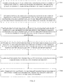
- FIG. 2 is a flowchart showing a method for controlling wireless charging according to an exemplary embodiment. As shown in FIG. 2 , the method includes the following steps S101 to S106.
- the user may, based on the first preset position relative to the wireless charging transmitter, move the wireless charging receiver to the first preset position relative to the wireless charging transmitter, and the corresponding first charging quality is acquired after the movement.
- the method for acquiring the charging quality is the same as the method for acquiring the current charging quality at the current position in step S101, and details are not described herein.
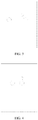
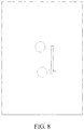
- the moving direction corresponding to the first preset position may be displayed to the user via the user interface (referred to as UI for short) of the wireless charging receiver, such as on a screen, as shown in FIG. 3 .
- the solid-line circle indicates the current position of the center of the charging coil of the wireless charging receiver
- the dotted-line circle indicates the first preset position to which the wireless charging receiver is to be moved.
- the display of the current position and the first preset position of the wireless charging receiver may be adjusted in real time.
- FIG. 5 when the solid-line circle and the dotted-line circle coincide, it indicates that the wireless charging receiver is moved to the first preset position.
- Step S103 upon movement of the wireless charging receiver from the first preset position to a second preset position relative to the wireless charging transmitter, acquiring charging quality of the wireless charging receiver at the second preset position relative to the wireless charging transmitter.
- the user may, based on a second preset position relative to the wireless charging transmitter, continue to move the wireless charging receiver to the second preset position relative to the wireless charging transmitter, and the corresponding second charging quality is acquired after the movement.
- the method for acquiring the charging quality is the same as the method for acquiring the current charging quality at the current position in step S101, and details are not described herein.
- a prompting method for the second preset position may be the same as that for the first preset position.
- a prompting method for the first preset position may be the same as that for the first preset position.
- Step S104 determining relative position information of the wireless charging receiver relative to the wireless charging transmitter, based on the current charging quality at the current position, the first charging quality and the second charging quality.
- Step S106 upon correction of a position of the wireless charging receiver based on the position correction information, charging the wireless charging receiver at the corrected position.
- this can be displayed to the user via the UI so that the user performs position correction on the wireless charging receiver, and after the position correction is completed, the wireless charging receiver is charged at the corrected position.
- a method for controlling wireless charging including:: acquiring charging quality of a wireless charging receiver at a current position relative to a wireless charging transmitter, the charging quality including coupling signal intensity or charging efficiency; upon movement of the wireless charging receiver from the current position to a first preset position relative to the wireless charging transmitter, acquiring charging quality of the wireless charging receiver at the first preset position relative to the wireless charging transmitter; upon movement of the wireless charging receiver from the first preset position to a second preset position relative to the wireless charging transmitter, acquiring charging quality of the wireless charging receiver at the second preset position relative to the wireless charging transmitter; determining relative position information of the wireless charging receiver relative to the wireless charging transmitter, based on the current charging quality at the current position, the first charging quality and the second charging quality; acquiring position correction information of the wireless charging receiver corresponding to the relative position information; and upon correction of a position of the wireless charging receiver based on the position correction information, charging the wireless charging receiver at the corrected position.
- the above step S104 includes following sub-steps A1 to A2.
- the target quadrant of the wireless charging receiver may be acquired based on the current charging quality at the current position, the first charging quality and the second charging quality. Based on the target quadrant, the relative position information of the wireless charging receiver relative to the wireless charging transmitter may be acquired.
- a preset rectangular coordinate system may be provided at the wireless charging transmitter, based on the charging efficiency in FIG. 1 .
- the left-right coordinate axis represents the axis corresponding to the zero-offset in the Y direction in FIG. 1
- the up-down coordinate axis represents the axis corresponding to the zero-offset in the X direction in FIG. 1
- the "+" represents the position of the center of the charging coil of the wireless charging receiver.
- the center of the charging coil of the wireless charging receiver is located anywhere in the four quadrants.
- when terms indicating directions such as left, right, up and down are used, they refer to the directions with respect to the preset rectangular coordinate system. They may or may not be the directions with respect to the user.
- the technical solution according to the embodiment of the present invention may have the following beneficial effects: by providing the preset rectangular coordinate system, the accuracy in determining the relative position information is improved.
- the center of the charging coil of the wireless charging receiver has to be moved to coincide with that of the wireless charging transmitter, as shown in FIG. 1 . Accordingly, the movement may be performed in accordance with the preset moving direction and the preset movement distance so that center of the charging coil of the wireless charging receiver coincides with that of the wireless charging transmitter.
- the preset moving direction includes a first preset direction
- the preset movement distance includes a first preset distance
- charging the wireless charging receiver at a position after the movement includes following sub-steps B1 to B4.
- the charging quality at the third position is lower than the second charging quality, it indicates that the charging quality is reduced, that is, the movement is incorrect.
- movement in the second preset direction opposite to the first preset direction is required.
- a second prompt message will be output to the user for prompting the user to move the wireless charging receiver by the first preset distance in the second preset direction.
- the second prompt message may be the interface display message similar to that in FIG. 3 , so that the user moves the wireless charging receiver in the direction indicated by the arrow.
- Step B4 in a case where the charging quality at the third position is higher than the second charging quality at the second preset position, repeating the step of outputting the first prompt message and acquiring the charging quality, until the charging quality of the wireless charging receiver at the position after the movement by the first preset distance in the first preset direction is lower than the charging quality of the wireless charging receiver before the movement, and outputting the second prompt message.
- the first prompt message is still output to the user for prompting the user to continue to move the wireless charging receiver by the first preset distance in the first preset direction, until the charging quality of the wireless charging receiver at the position after the movement by the first preset distance in the first preset direction is lower than the charging quality of the wireless charging receiver before the movement, which indicates that the charging quality is reduced (i.e., the movement is incorrect), and the charging quality at the adjacent previous position is the highest. Then, the wireless charging receiver should be moved back to the adjacent previous position, that is, the wireless charging receiver should be moved in the second preset direction opposite to the first preset direction.
- a second prompt message will be output to the user for prompting the user to move the wireless charging receiver by the first preset distance in the second preset direction.
- the wireless charging receiver upon movement of the wireless charging receiver by the first preset distance in the second preset direction, the wireless charging receiver is charged at the position after the movement.
- the charging quality after the movement in the preset second direction is higher than that before the movement, the charging quality is effectively improved by charging the wireless charging receiver at the position after the movement by the first preset distance in the second preset direction.
- the preset moving direction further includes a third preset direction
- the preset movement distance further includes a second preset distance
- the method further includes following sub-steps C1 to C6.
- the charging quality of the wireless charging receiver at the fourth position is acquired after the movement to the fourth position.
- a third prompt information is output to the user for prompting the user to move the wireless charging receiver by the second preset distance in the third preset direction, so that the user moves the wireless charging receiver by the second preset distance in the third preset direction.
- the charging quality being the charging efficiency as an example, as shown in FIG. 1 , it is assumed that when the wireless charging receiver is moved by the first preset distance in the second preset direction to the fourth position relative to the wireless charging transmitter, the acquired charging efficiency of the wireless charging receiver at the fourth position is 78.8%. Although the charging efficiency of 78.8% is the highest in the lateral direction or the X direction, it is not the highest in the longitudinal direction or the Y direction, because it is also possible to achieve a charging efficiency of 81.6%. Therefore, it is desirable to continue to move the wireless charging receiver in the longitudinal direction or the vertical direction, until the charging quality reaches 81.6%.
- Step C3 upon movement of the wireless charging receiver by the second preset distance in the third preset direction to a fifth position relative to the wireless charging transmitter, acquiring charging quality of the wireless charging receiver at the fifth position.
- Step C4 in a case where the charging quality at the fifth position is lower than the charging quality at the fourth position, outputting a fourth prompt message, the fourth prompt message prompting the wireless charging receiver to move by the second preset distance in a fourth preset direction, the fourth preset direction being opposite to the third preset direction.
- Step C5 in a case where the charging quality at the fifth position is higher than the charging quality at the fourth position, repeating the step of outputting the third prompt message and acquiring the charging quality, until the charging quality of the wireless charging receiver at the position after the movement by the second preset distance in the third preset direction is lower than the charging quality of the wireless charging receiver before the movement, and outputting the fourth prompt message.
- the charging quality at the fifth position is higher than the charging quality at the fourth position, it indicates that the charging quality is improved, that is, the movement is correct. However, it does not indicate that the charging quality at the fifth position is the highest.
- the third prompt message is still output to the user for prompting the user to continue to move the wireless charging receiver by the second preset distance in the third preset direction. After the movement, the charging quality at the new position is acquired. In a case where the charging quality at the new position is still higher than the charging quality at the adjacent previous or last position, it indicates that the charging quality is improved, that is, the movement is correct. However, it still does not indicate that the charging quality at the new position is the highest.
- the third prompt message is still output to the user for prompting the user to continue to move the wireless charging receiver by the second preset distance in the third preset direction, until the charging quality of the wireless charging receiver at the position after the movement by the second preset distance in the third preset direction is lower than the charging quality of the wireless charging receiver before the movement, which indicates that the charging quality is reduced (i.e., the movement is incorrect), and the charging quality at the adjacent previous position is the highest. Then, the wireless charging receiver has to be moved back to the previous position, that is, the wireless charging receiver has to be moved in the fourth preset direction opposite to the third preset direction.
- a fourth prompt message will be output to the user for prompting the user to move the wireless charging receiver by the second preset distance in the fourth preset direction.
- Step C6 upon movement of the wireless charging receiver by the second preset distance in the fourth preset direction, charging the wireless charging receiver at the position after the movement.
- Step S201 acquiring charging efficiency of a wireless charging receiver at a current position relative to a wireless charging transmitter.
- the wireless charging receiver and the wireless charging transmitter perform the protocol interaction based on the Qi standard, and the wireless charging receiver is charged after the protocol communication is completed.
- the wireless charging receiver acquires the input voltage and current of the wireless charging transmitter, and acquires the charging efficiency ⁇ 1 at the current position according to its own output voltage and current.
- Step S202 upon movement of the wireless charging receiver from the current position to a first preset position relative to the wireless charging transmitter, acquiring charging efficiency of the wireless charging receiver at the first preset position relative to the wireless charging transmitter.
- the first preset position may be a position after the movement to the right by the preset length, for example 1mm.
- the interface of the wireless charging receiver displays the center position of the charging coil of the wireless charging receiver and the position after the movement to the right by 1mm.
- the user's hand moves to the right by 1mm according to the display of the UI interface, until the solid-line circle is moved to coincide with the dotted-line circle, so that the wireless charging receiver is moved to the first preset position.
- the wireless charging receiver calculates the charging efficiency ⁇ 2 at the first preset position.
- the wireless charging receiver will know the target quadrant, in the preset rectangular coordinate system at the wireless charging transmitter, where the wireless charging receiver is located.
- Step S206 acquiring position correction information of the wireless charging receiver corresponding to the relative position information, wherein the position correction information includes a preset moving direction and a preset movement distance, the preset moving direction includes a first preset direction, the preset movement distance includes a first preset distance, the preset moving direction further includes a third preset direction, and the preset movement distance further includes a second preset distance.
- the position correction information includes a preset moving direction and a preset movement distance
- the preset moving direction includes a first preset direction
- the preset movement distance includes a first preset distance
- the preset moving direction further includes a third preset direction
- the preset movement distance further includes a second preset distance.
- Step S2011 upon movement of the wireless charging receiver by the first preset distance in the second preset direction to a fourth position relative to the wireless charging transmitter, acquiring charging efficiency of the wireless charging receiver at the fourth position.
- Step S2012 outputting a third prompt message, the third prompt message prompting the wireless charging receiver to move by the second preset distance in the third preset direction.
- the UI prompts the user to complete the alignment in a range of ⁇ 2 mm between the center of the charging coil of the wireless charging receiver and the center of the charging coil of the wireless charging transmitter in the up-down direction.
- Step S2016 upon movement of the wireless charging receiver by the second preset distance in the fourth preset direction, charging the wireless charging receiver at the position after the movement.
- the first determining sub-module 141 is configured to determine a target quadrant of the wireless charging receiver in a preset rectangular coordinate system provided at the wireless charging transmitter, based on the current charging quality at the current position acquired by the first acquiring module 11, the first charging quality acquired by the second acquiring module 12 and the second charging quality acquired by the third acquiring module 13.
- An intersection of two axes of the preset rectangular coordinate system is a center of a charging coil in the wireless charging transmitter.
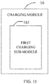
- the first charging sub-module 161 is configured to, upon movement of the wireless charging receiver in accordance with the preset moving direction and the preset movement distance acquired by the fourth acquiring module 15, charge the wireless charging receiver at a position after the movement.
- the preset moving direction includes a first preset direction
- the preset movement distance includes a first preset distance
- the first charging sub-module 161 includes a first outputting sub-module 1611, a first acquiring sub-module 1612, a second outputting sub-module 1613 and a first repeating sub-module 1614.
- the first acquiring sub-module 1612 is configured to, upon movement of the wireless charging receiver by the first preset distance in the first preset direction output by the first outputting sub-module 1611 to a third position relative to the wireless charging transmitter, acquire charging quality of the wireless charging receiver at the third position.
- the second outputting sub-module 1613 is configured to, in a case where the charging quality at the third position is lower than the second charging quality, output a second prompt message, the second prompt message prompting the wireless charging receiver to move by the first preset distance in a second preset direction, the second preset direction being opposite to the first preset direction.
- the first repeating sub-module 1614 is configured to, in a case where the charging quality at the third position is higher than the second charging quality, repeat the step of outputting the first prompt message and acquiring the charging quality, until the charging quality of the wireless charging receiver at the position after the movement by the first preset distance in the first preset direction is lower than the charging quality of the wireless charging receiver before the movement, and output the second prompt message.
- the first charging sub-module 161 further includes a second charging sub-module 1615.
- the preset moving direction further includes a third preset direction
- the preset movement distance further includes a second preset distance
- the first charging sub-module 161 further includes a second acquiring sub-module 1616, a third outputting sub-module 1617, a third acquiring sub-module 1618, a fourth outputting sub-module 1619, a second repeating sub-module 16110 and a second charging sub-module 16111.
- the second acquiring sub-module 1616 is configured to, upon movement of the wireless charging receiver by the first preset distance in the second preset direction to a fourth position relative to the wireless charging transmitter, acquire charging quality of the wireless charging receiver at the fourth position.
- the third outputting sub-module 1617 is configured to output a third prompt message, the third prompt message prompting the wireless charging receiver to move by the second preset distance in the third preset direction.
- the third acquiring sub-module 1618 is configured to, upon movement of the wireless charging receiver by the second preset distance in the third preset direction to a fifth position relative to the wireless charging transmitter, acquire charging quality of the wireless charging receiver at the fifth position.
- the fourth outputting sub-module 1619 is configured to, in a case where the charging quality at the fifth position is lower than the charging quality at the fourth position, output a fourth prompt message, the fourth prompt message prompting the wireless charging receiver to move by the second preset distance in a fourth preset direction, the fourth preset direction being opposite to the third preset direction.
- the second repeating sub-module 16110 is configured to, in a case where the charging quality at the fifth position is higher than the charging quality at the fourth position, repeat the step of outputting the third prompt message and acquiring the charging quality, until the charging quality of the wireless charging receiver at the position after the movement by the second preset distance in the third preset direction is lower than the charging quality of the wireless charging receiver before the movement, and output the fourth prompt message.
- the second charging sub-module 16111 is configured to, upon movement of the wireless charging receiver by the second preset distance in the fourth preset direction, charge the wireless charging receiver at the position after the movement.
- a device for controlling wireless charging includes:
- the above processor may be further configured as follows.
- Said determining relative position information of the wireless charging receiver relative to the wireless charging transmitter, based on the current charging quality at the current position, the first charging quality and the second charging quality includes:
- the position correction information includes a preset moving direction and a preset movement distance, and said upon correction of a position of the wireless charging receiver based on the position correction information, charging the wireless charging receiver at the corrected position includes: upon movement of the wireless charging receiver in accordance with the preset moving direction and the preset movement distance, charging the wireless charging receiver at a position after the movement.
- the preset moving direction includes a first preset direction
- the preset movement distance includes a first preset distance
- charging the wireless charging receiver at a position after the movement includes:
- Said charging the wireless charging receiver at a position after the movement upon movement of the wireless charging receiver in accordance with the preset moving direction and the preset movement distance further includes: upon movement of the wireless charging receiver by the first preset distance in the second preset direction, charging the wireless charging receiver at the position after the movement.
- the preset moving direction further includes a third preset direction
- the preset movement distance further includes a second preset distance
- the method further includes:
- FIG. 15 is a block diagram showing a device 80 for controlling wireless charging according to an exemplary embodiment.
- the device 80 is applicable to a terminal device.
- the device 80 may be a mobile phone, a computer, a digital broadcast terminal, a messaging device, a gaming console, a tablet, a medical device, exercise equipment, a personal digital assistant, and the like.
- the device 80 may include one or more of the following components: a processing component 802, a memory 804, a power component 806, a multimedia component 808, an audio component 810, an input/output (I/O) interface 812, a sensor component 814, and a communication component 816.
- a processing component 802 a memory 804, a power component 806, a multimedia component 808, an audio component 810, an input/output (I/O) interface 812, a sensor component 814, and a communication component 816.
- the power component 806 provides power to various components of the device 80.
- the power component 806 may include a power management system, one or more power sources, and any other components associated with the generation, management, and distribution of power in the device 80.
- the multimedia component 808 includes a screen providing an output interface between the device 80 and the user.
- the screen may include a liquid crystal display (LCD) and a touch panel (TP). If the screen includes the touch panel, the screen may be implemented as a touch screen to receive input signals from the user.
- the touch panel includes one or more touch sensors to sense touches, swipes, and gestures on the touch panel. The touch sensors may not only sense a boundary of a touch or swipe action, but also sense a period of time and a pressure associated with the touch or swipe action.
- the multimedia component 808 includes a front camera and/or a rear camera.
- the front camera and/or the rear camera may receive an external multimedia datum while the device 80 is in an operation mode, such as a photographing mode or a video mode.
- an operation mode such as a photographing mode or a video mode.
- Each of the front camera and the rear camera may be a fixed optical lens system or have focus and optical zoom capability.
- the audio component 810 is configured to output and/or input audio signals.
- the audio component 810 includes a microphone ("MIC") configured to receive an external audio signal when the device 80 is in an operation mode, such as a call mode, a recording mode, and a voice recognition mode.
- the received audio signal may be further stored in the memory 804 or transmitted via the communication component 816.
- the audio component 810 further includes a speaker to output audio signals.
- the I/O interface 812 provides an interface between the processing component 802 and peripheral interface modules, such as a keyboard, a click wheel, buttons, and the like.
- the buttons may include, but are not limited to, a home button, a volume button, a starting button, and a locking button.
- the communication component 816 is configured to facilitate communication, wired or wirelessly, between the device 80 and other devices.
- the device 80 can access a wireless network based on a communication standard, such as WiFi, 2G, or 3G, or a combination thereof.
- the communication component 816 receives a broadcast signal or broadcast associated information from an external broadcast management system via a broadcast channel.
- the communication component 816 further includes a near field communication (NFC) module to facilitate short-range communications.
- the NFC module may be implemented based on a radio frequency identification (RFID) technology, an infrared data association (IrDA) technology, an ultra-wideband (UWB) technology, a Bluetooth (BT) technology, and other technologies.
- RFID radio frequency identification
- IrDA infrared data association
- UWB ultra-wideband
- BT Bluetooth
- Said charging the wireless charging receiver at a position after the movement upon movement of the wireless charging receiver in accordance with the preset moving direction and the preset movement distance further includes: upon movement of the wireless charging receiver by the first preset distance in the second preset direction, charging the wireless charging receiver at the position after the movement.
Landscapes
- Engineering & Computer Science (AREA)
- Computer Networks & Wireless Communication (AREA)
- Power Engineering (AREA)
- Software Systems (AREA)
- Theoretical Computer Science (AREA)
- Physics & Mathematics (AREA)
- General Engineering & Computer Science (AREA)
- General Physics & Mathematics (AREA)
- Charge And Discharge Circuits For Batteries Or The Like (AREA)
Applications Claiming Priority (1)
| Application Number | Priority Date | Filing Date | Title |
|---|---|---|---|
| CN201810322306.7A CN108599385B (zh) | 2018-04-11 | 2018-04-11 | 无线充电的控制方法及装置 |
Publications (2)
| Publication Number | Publication Date |
|---|---|
| EP3553919A1 true EP3553919A1 (de) | 2019-10-16 |
| EP3553919B1 EP3553919B1 (de) | 2022-06-01 |
Family
ID=63621875
Family Applications (1)
| Application Number | Title | Priority Date | Filing Date |
|---|---|---|---|
| EP19168468.7A Active EP3553919B1 (de) | 2018-04-11 | 2019-04-10 | Verfahren und vorrichtung zur steuerung des drahtlosen ladens |
Country Status (3)
| Country | Link |
|---|---|
| US (1) | US11201510B2 (de) |
| EP (1) | EP3553919B1 (de) |
| CN (1) | CN108599385B (de) |
Families Citing this family (4)
| Publication number | Priority date | Publication date | Assignee | Title |
|---|---|---|---|---|
| CN110474437B (zh) * | 2019-08-30 | 2022-08-02 | 维沃移动通信有限公司 | 一种无线充电方法及相关设备 |
| CN112769253B (zh) * | 2019-11-04 | 2023-12-26 | 北京小米移动软件有限公司 | 无线充电方法、装置、无线充电发射器及存储介质 |
| CN116191697A (zh) * | 2023-02-24 | 2023-05-30 | 创烨新材料(苏州)有限公司 | 一种智能家居网络无线充电的方法、装置及系统 |
| WO2026048000A1 (ja) * | 2024-08-30 | 2026-03-05 | Ntt株式会社 | 空間型電力伝送システム |
Citations (4)
| Publication number | Priority date | Publication date | Assignee | Title |
|---|---|---|---|---|
| WO2015096997A1 (de) * | 2013-12-23 | 2015-07-02 | Continental Automotive Gmbh | Verfahren zur erfassung einer relativposition, verfahren zum kabellosen laden eines fahrzeugs, orientierungssignalempfänger und induktive ladevorrichtung |
| CN107154685A (zh) * | 2017-05-27 | 2017-09-12 | 维沃移动通信有限公司 | 一种无线充电底座对位的提示方法和移动终端 |
| US20170338682A1 (en) * | 2016-05-20 | 2017-11-23 | Lenovo (Beijing) Co., Ltd. | Charging position prompting method and electronic device |
| CN107394908A (zh) * | 2017-08-07 | 2017-11-24 | 维沃移动通信有限公司 | 一种无线充电方法、移动终端和充电设备 |
Family Cites Families (1)
| Publication number | Priority date | Publication date | Assignee | Title |
|---|---|---|---|---|
| US9626258B2 (en) * | 2014-03-26 | 2017-04-18 | Qualcomm Incorporated | Systems, methods, and apparatus related to wireless charging management |
-
2018
- 2018-04-11 CN CN201810322306.7A patent/CN108599385B/zh active Active
-
2019
- 2019-04-10 EP EP19168468.7A patent/EP3553919B1/de active Active
- 2019-04-15 US US16/384,357 patent/US11201510B2/en active Active
Patent Citations (4)
| Publication number | Priority date | Publication date | Assignee | Title |
|---|---|---|---|---|
| WO2015096997A1 (de) * | 2013-12-23 | 2015-07-02 | Continental Automotive Gmbh | Verfahren zur erfassung einer relativposition, verfahren zum kabellosen laden eines fahrzeugs, orientierungssignalempfänger und induktive ladevorrichtung |
| US20170338682A1 (en) * | 2016-05-20 | 2017-11-23 | Lenovo (Beijing) Co., Ltd. | Charging position prompting method and electronic device |
| CN107154685A (zh) * | 2017-05-27 | 2017-09-12 | 维沃移动通信有限公司 | 一种无线充电底座对位的提示方法和移动终端 |
| CN107394908A (zh) * | 2017-08-07 | 2017-11-24 | 维沃移动通信有限公司 | 一种无线充电方法、移动终端和充电设备 |
Also Published As
| Publication number | Publication date |
|---|---|
| US20190319496A1 (en) | 2019-10-17 |
| EP3553919B1 (de) | 2022-06-01 |
| CN108599385B (zh) | 2021-08-06 |
| CN108599385A (zh) | 2018-09-28 |
| US11201510B2 (en) | 2021-12-14 |
Similar Documents
| Publication | Publication Date | Title |
|---|---|---|
| US11061202B2 (en) | Methods and devices for adjusting lens position | |
| EP3553919B1 (de) | Verfahren und vorrichtung zur steuerung des drahtlosen ladens | |
| EP3125531A1 (de) | Steuerungsverfahren und -vorrichtung zur einstellung einer schiessvorrichtung | |
| US9729775B2 (en) | Auto-focusing method and auto-focusing device | |
| EP3133528A1 (de) | Verfahren und vorrichtung zur fingerabdruckidentifikation | |
| US11457437B2 (en) | Method and apparatus for configuring information, base station and user equipment | |
| US9491371B2 (en) | Method and device for configuring photographing parameters | |
| EP3046212B1 (de) | Verfahren und vorrichtung zur steuerung des ladevorgangs einer endgerätevorrichtung | |
| EP3260362A1 (de) | Weitergabe der steuerungsberechtigung für ein gesteuertes endgerät | |
| EP3136699A1 (de) | Verfahren und vorrichtung zur verbindung einer externen ausrüstung | |
| EP3024211B1 (de) | Verfahren und vorrichtung zur ankündigung eines sprachanrufs | |
| EP3322227A1 (de) | Verfahren und vorrichtungen zur steuerung einer drahtlosen verbindung, computerprogramm und aufzeichnungsmedium | |
| US10318069B2 (en) | Method for controlling state of touch screen, and electronic device and medium for implementing the same | |
| CN108718439B (zh) | 数据传输方法及装置 | |
| EP3119040A1 (de) | Verfahren und vorrichtung zur steuerung einer intelligenten vorrichtung | |
| CN105516586A (zh) | 图片拍摄方法、装置及系统 | |
| EP3614711A1 (de) | Verfahren zur ausgabe von vernetzungsauthentifizierungsinformationen, vernetzungsverfahren, vorrichtung und speichermedium | |
| CN105337368A (zh) | 终端充电方法及装置 | |
| US20220294989A1 (en) | Method and apparatus for processing image | |
| EP3125514A1 (de) | Verfahren und vorrichtung zur statusbenachrichtigung | |
| CN103973883B (zh) | 一种控制语音输入设备的方法及装置 | |
| EP3176740A1 (de) | Informationsverarbeitungsverfahren und -vorrichtung, computerprogramm und aufzeichnungsmedium | |
| US11418058B2 (en) | Wireless charging system, method for determining charging region, electronic device, and computer-readable storage medium | |
| EP3188018A1 (de) | Verfahren und vorrichtung zur einstellung der wartezeitdauer | |
| CN112242754A (zh) | 无线充电定位方法、装置及移动终端 |
Legal Events
| Date | Code | Title | Description |
|---|---|---|---|
| PUAI | Public reference made under article 153(3) epc to a published international application that has entered the european phase |
Free format text: ORIGINAL CODE: 0009012 |
|
| STAA | Information on the status of an ep patent application or granted ep patent |
Free format text: STATUS: THE APPLICATION HAS BEEN PUBLISHED |
|
| AK | Designated contracting states |
Kind code of ref document: A1 Designated state(s): AL AT BE BG CH CY CZ DE DK EE ES FI FR GB GR HR HU IE IS IT LI LT LU LV MC MK MT NL NO PL PT RO RS SE SI SK SM TR |
|
| AX | Request for extension of the european patent |
Extension state: BA ME |
|
| STAA | Information on the status of an ep patent application or granted ep patent |
Free format text: STATUS: REQUEST FOR EXAMINATION WAS MADE |
|
| 17P | Request for examination filed |
Effective date: 20200416 |
|
| RBV | Designated contracting states (corrected) |
Designated state(s): AL AT BE BG CH CY CZ DE DK EE ES FI FR GB GR HR HU IE IS IT LI LT LU LV MC MK MT NL NO PL PT RO RS SE SI SK SM TR |
|
| STAA | Information on the status of an ep patent application or granted ep patent |
Free format text: STATUS: EXAMINATION IS IN PROGRESS |
|
| 17Q | First examination report despatched |
Effective date: 20200708 |
|
| GRAP | Despatch of communication of intention to grant a patent |
Free format text: ORIGINAL CODE: EPIDOSNIGR1 |
|
| STAA | Information on the status of an ep patent application or granted ep patent |
Free format text: STATUS: GRANT OF PATENT IS INTENDED |
|
| INTG | Intention to grant announced |
Effective date: 20211215 |
|
| GRAS | Grant fee paid |
Free format text: ORIGINAL CODE: EPIDOSNIGR3 |
|
| GRAA | (expected) grant |
Free format text: ORIGINAL CODE: 0009210 |
|
| STAA | Information on the status of an ep patent application or granted ep patent |
Free format text: STATUS: THE PATENT HAS BEEN GRANTED |
|
| AK | Designated contracting states |
Kind code of ref document: B1 Designated state(s): AL AT BE BG CH CY CZ DE DK EE ES FI FR GB GR HR HU IE IS IT LI LT LU LV MC MK MT NL NO PL PT RO RS SE SI SK SM TR |
|
| REG | Reference to a national code |
Ref country code: GB Ref legal event code: FG4D |
|
| REG | Reference to a national code |
Ref country code: AT Ref legal event code: REF Ref document number: 1496066 Country of ref document: AT Kind code of ref document: T Effective date: 20220615 Ref country code: CH Ref legal event code: EP |
|
| REG | Reference to a national code |
Ref country code: IE Ref legal event code: FG4D |
|
| REG | Reference to a national code |
Ref country code: DE Ref legal event code: R096 Ref document number: 602019015324 Country of ref document: DE |
|
| REG | Reference to a national code |
Ref country code: LT Ref legal event code: MG9D |
|
| REG | Reference to a national code |
Ref country code: NL Ref legal event code: MP Effective date: 20220601 |
|
| PG25 | Lapsed in a contracting state [announced via postgrant information from national office to epo] |
Ref country code: SE Free format text: LAPSE BECAUSE OF FAILURE TO SUBMIT A TRANSLATION OF THE DESCRIPTION OR TO PAY THE FEE WITHIN THE PRESCRIBED TIME-LIMIT Effective date: 20220601 Ref country code: NO Free format text: LAPSE BECAUSE OF FAILURE TO SUBMIT A TRANSLATION OF THE DESCRIPTION OR TO PAY THE FEE WITHIN THE PRESCRIBED TIME-LIMIT Effective date: 20220901 Ref country code: LT Free format text: LAPSE BECAUSE OF FAILURE TO SUBMIT A TRANSLATION OF THE DESCRIPTION OR TO PAY THE FEE WITHIN THE PRESCRIBED TIME-LIMIT Effective date: 20220601 Ref country code: HR Free format text: LAPSE BECAUSE OF FAILURE TO SUBMIT A TRANSLATION OF THE DESCRIPTION OR TO PAY THE FEE WITHIN THE PRESCRIBED TIME-LIMIT Effective date: 20220601 Ref country code: GR Free format text: LAPSE BECAUSE OF FAILURE TO SUBMIT A TRANSLATION OF THE DESCRIPTION OR TO PAY THE FEE WITHIN THE PRESCRIBED TIME-LIMIT Effective date: 20220902 Ref country code: FI Free format text: LAPSE BECAUSE OF FAILURE TO SUBMIT A TRANSLATION OF THE DESCRIPTION OR TO PAY THE FEE WITHIN THE PRESCRIBED TIME-LIMIT Effective date: 20220601 Ref country code: ES Free format text: LAPSE BECAUSE OF FAILURE TO SUBMIT A TRANSLATION OF THE DESCRIPTION OR TO PAY THE FEE WITHIN THE PRESCRIBED TIME-LIMIT Effective date: 20220601 Ref country code: BG Free format text: LAPSE BECAUSE OF FAILURE TO SUBMIT A TRANSLATION OF THE DESCRIPTION OR TO PAY THE FEE WITHIN THE PRESCRIBED TIME-LIMIT Effective date: 20220901 |
|
| REG | Reference to a national code |
Ref country code: AT Ref legal event code: MK05 Ref document number: 1496066 Country of ref document: AT Kind code of ref document: T Effective date: 20220601 |
|
| PG25 | Lapsed in a contracting state [announced via postgrant information from national office to epo] |
Ref country code: RS Free format text: LAPSE BECAUSE OF FAILURE TO SUBMIT A TRANSLATION OF THE DESCRIPTION OR TO PAY THE FEE WITHIN THE PRESCRIBED TIME-LIMIT Effective date: 20220601 Ref country code: PL Free format text: LAPSE BECAUSE OF FAILURE TO SUBMIT A TRANSLATION OF THE DESCRIPTION OR TO PAY THE FEE WITHIN THE PRESCRIBED TIME-LIMIT Effective date: 20220601 Ref country code: LV Free format text: LAPSE BECAUSE OF FAILURE TO SUBMIT A TRANSLATION OF THE DESCRIPTION OR TO PAY THE FEE WITHIN THE PRESCRIBED TIME-LIMIT Effective date: 20220601 |
|
| PG25 | Lapsed in a contracting state [announced via postgrant information from national office to epo] |
Ref country code: NL Free format text: LAPSE BECAUSE OF FAILURE TO SUBMIT A TRANSLATION OF THE DESCRIPTION OR TO PAY THE FEE WITHIN THE PRESCRIBED TIME-LIMIT Effective date: 20220601 |
|
| PG25 | Lapsed in a contracting state [announced via postgrant information from national office to epo] |
Ref country code: SM Free format text: LAPSE BECAUSE OF FAILURE TO SUBMIT A TRANSLATION OF THE DESCRIPTION OR TO PAY THE FEE WITHIN THE PRESCRIBED TIME-LIMIT Effective date: 20220601 Ref country code: SK Free format text: LAPSE BECAUSE OF FAILURE TO SUBMIT A TRANSLATION OF THE DESCRIPTION OR TO PAY THE FEE WITHIN THE PRESCRIBED TIME-LIMIT Effective date: 20220601 Ref country code: RO Free format text: LAPSE BECAUSE OF FAILURE TO SUBMIT A TRANSLATION OF THE DESCRIPTION OR TO PAY THE FEE WITHIN THE PRESCRIBED TIME-LIMIT Effective date: 20220601 Ref country code: PT Free format text: LAPSE BECAUSE OF FAILURE TO SUBMIT A TRANSLATION OF THE DESCRIPTION OR TO PAY THE FEE WITHIN THE PRESCRIBED TIME-LIMIT Effective date: 20221003 Ref country code: EE Free format text: LAPSE BECAUSE OF FAILURE TO SUBMIT A TRANSLATION OF THE DESCRIPTION OR TO PAY THE FEE WITHIN THE PRESCRIBED TIME-LIMIT Effective date: 20220601 Ref country code: CZ Free format text: LAPSE BECAUSE OF FAILURE TO SUBMIT A TRANSLATION OF THE DESCRIPTION OR TO PAY THE FEE WITHIN THE PRESCRIBED TIME-LIMIT Effective date: 20220601 Ref country code: AT Free format text: LAPSE BECAUSE OF FAILURE TO SUBMIT A TRANSLATION OF THE DESCRIPTION OR TO PAY THE FEE WITHIN THE PRESCRIBED TIME-LIMIT Effective date: 20220601 |
|
| PG25 | Lapsed in a contracting state [announced via postgrant information from national office to epo] |
Ref country code: IS Free format text: LAPSE BECAUSE OF FAILURE TO SUBMIT A TRANSLATION OF THE DESCRIPTION OR TO PAY THE FEE WITHIN THE PRESCRIBED TIME-LIMIT Effective date: 20221001 |
|
| REG | Reference to a national code |
Ref country code: DE Ref legal event code: R097 Ref document number: 602019015324 Country of ref document: DE |
|
| PG25 | Lapsed in a contracting state [announced via postgrant information from national office to epo] |
Ref country code: AL Free format text: LAPSE BECAUSE OF FAILURE TO SUBMIT A TRANSLATION OF THE DESCRIPTION OR TO PAY THE FEE WITHIN THE PRESCRIBED TIME-LIMIT Effective date: 20220601 |
|
| PLBE | No opposition filed within time limit |
Free format text: ORIGINAL CODE: 0009261 |
|
| STAA | Information on the status of an ep patent application or granted ep patent |
Free format text: STATUS: NO OPPOSITION FILED WITHIN TIME LIMIT |
|
| PG25 | Lapsed in a contracting state [announced via postgrant information from national office to epo] |
Ref country code: DK Free format text: LAPSE BECAUSE OF FAILURE TO SUBMIT A TRANSLATION OF THE DESCRIPTION OR TO PAY THE FEE WITHIN THE PRESCRIBED TIME-LIMIT Effective date: 20220601 |
|
| 26N | No opposition filed |
Effective date: 20230302 |
|
| PG25 | Lapsed in a contracting state [announced via postgrant information from national office to epo] |
Ref country code: SI Free format text: LAPSE BECAUSE OF FAILURE TO SUBMIT A TRANSLATION OF THE DESCRIPTION OR TO PAY THE FEE WITHIN THE PRESCRIBED TIME-LIMIT Effective date: 20220601 |
|
| P01 | Opt-out of the competence of the unified patent court (upc) registered |
Effective date: 20230523 |
|
| REG | Reference to a national code |
Ref country code: CH Ref legal event code: PL |
|
| PG25 | Lapsed in a contracting state [announced via postgrant information from national office to epo] |
Ref country code: LU Free format text: LAPSE BECAUSE OF NON-PAYMENT OF DUE FEES Effective date: 20230410 |
|
| REG | Reference to a national code |
Ref country code: BE Ref legal event code: MM Effective date: 20230430 |
|
| PG25 | Lapsed in a contracting state [announced via postgrant information from national office to epo] |
Ref country code: MC Free format text: LAPSE BECAUSE OF FAILURE TO SUBMIT A TRANSLATION OF THE DESCRIPTION OR TO PAY THE FEE WITHIN THE PRESCRIBED TIME-LIMIT Effective date: 20220601 |
|
| PG25 | Lapsed in a contracting state [announced via postgrant information from national office to epo] |
Ref country code: MC Free format text: LAPSE BECAUSE OF FAILURE TO SUBMIT A TRANSLATION OF THE DESCRIPTION OR TO PAY THE FEE WITHIN THE PRESCRIBED TIME-LIMIT Effective date: 20220601 Ref country code: LI Free format text: LAPSE BECAUSE OF NON-PAYMENT OF DUE FEES Effective date: 20230430 Ref country code: IT Free format text: LAPSE BECAUSE OF FAILURE TO SUBMIT A TRANSLATION OF THE DESCRIPTION OR TO PAY THE FEE WITHIN THE PRESCRIBED TIME-LIMIT Effective date: 20220601 Ref country code: CH Free format text: LAPSE BECAUSE OF NON-PAYMENT OF DUE FEES Effective date: 20230430 |
|
| REG | Reference to a national code |
Ref country code: IE Ref legal event code: MM4A |
|
| PG25 | Lapsed in a contracting state [announced via postgrant information from national office to epo] |
Ref country code: BE Free format text: LAPSE BECAUSE OF NON-PAYMENT OF DUE FEES Effective date: 20230430 |
|
| PG25 | Lapsed in a contracting state [announced via postgrant information from national office to epo] |
Ref country code: IE Free format text: LAPSE BECAUSE OF NON-PAYMENT OF DUE FEES Effective date: 20230410 |
|
| PG25 | Lapsed in a contracting state [announced via postgrant information from national office to epo] |
Ref country code: IE Free format text: LAPSE BECAUSE OF NON-PAYMENT OF DUE FEES Effective date: 20230410 |
|
| PG25 | Lapsed in a contracting state [announced via postgrant information from national office to epo] |
Ref country code: BG Free format text: LAPSE BECAUSE OF FAILURE TO SUBMIT A TRANSLATION OF THE DESCRIPTION OR TO PAY THE FEE WITHIN THE PRESCRIBED TIME-LIMIT Effective date: 20220601 |
|
| PG25 | Lapsed in a contracting state [announced via postgrant information from national office to epo] |
Ref country code: BG Free format text: LAPSE BECAUSE OF FAILURE TO SUBMIT A TRANSLATION OF THE DESCRIPTION OR TO PAY THE FEE WITHIN THE PRESCRIBED TIME-LIMIT Effective date: 20220601 |
|
| PGFP | Annual fee paid to national office [announced via postgrant information from national office to epo] |
Ref country code: DE Payment date: 20250422 Year of fee payment: 7 |
|
| PG25 | Lapsed in a contracting state [announced via postgrant information from national office to epo] |
Ref country code: CY Free format text: LAPSE BECAUSE OF FAILURE TO SUBMIT A TRANSLATION OF THE DESCRIPTION OR TO PAY THE FEE WITHIN THE PRESCRIBED TIME-LIMIT; INVALID AB INITIO Effective date: 20190410 |
|
| PG25 | Lapsed in a contracting state [announced via postgrant information from national office to epo] |
Ref country code: HU Free format text: LAPSE BECAUSE OF FAILURE TO SUBMIT A TRANSLATION OF THE DESCRIPTION OR TO PAY THE FEE WITHIN THE PRESCRIBED TIME-LIMIT; INVALID AB INITIO Effective date: 20190410 |
|
| PG25 | Lapsed in a contracting state [announced via postgrant information from national office to epo] |
Ref country code: TR Free format text: LAPSE BECAUSE OF FAILURE TO SUBMIT A TRANSLATION OF THE DESCRIPTION OR TO PAY THE FEE WITHIN THE PRESCRIBED TIME-LIMIT Effective date: 20220601 |
|
| PGFP | Annual fee paid to national office [announced via postgrant information from national office to epo] |
Ref country code: GB Payment date: 20260223 Year of fee payment: 8 |
|
| PGFP | Annual fee paid to national office [announced via postgrant information from national office to epo] |
Ref country code: FR Payment date: 20260223 Year of fee payment: 8 |