EP3553911A1 - Mikronetzsystem und verfahren zur verwaltung von fehlfunktionen - Google Patents
Mikronetzsystem und verfahren zur verwaltung von fehlfunktionen Download PDFInfo
- Publication number
- EP3553911A1 EP3553911A1 EP17877559.9A EP17877559A EP3553911A1 EP 3553911 A1 EP3553911 A1 EP 3553911A1 EP 17877559 A EP17877559 A EP 17877559A EP 3553911 A1 EP3553911 A1 EP 3553911A1
- Authority
- EP
- European Patent Office
- Prior art keywords
- failure
- ess
- microgrid
- pcs
- distributed
- Prior art date
- Legal status (The legal status is an assumption and is not a legal conclusion. Google has not performed a legal analysis and makes no representation as to the accuracy of the status listed.)
- Granted
Links
- 238000000034 method Methods 0.000 title description 23
- 230000007257 malfunction Effects 0.000 title 1
- 238000012544 monitoring process Methods 0.000 claims abstract description 24
- 230000002159 abnormal effect Effects 0.000 claims abstract description 4
- 238000012545 processing Methods 0.000 claims abstract description 3
- 238000005259 measurement Methods 0.000 claims description 32
- 238000007726 management method Methods 0.000 claims description 28
- 230000000903 blocking effect Effects 0.000 claims description 13
- 230000008859 change Effects 0.000 claims description 12
- 238000001514 detection method Methods 0.000 claims description 11
- 238000004891 communication Methods 0.000 claims description 5
- 229920003258 poly(methylsilmethylene) Polymers 0.000 description 80
- 238000009826 distribution Methods 0.000 description 31
- 241001672018 Cercomela melanura Species 0.000 description 7
- 238000010586 diagram Methods 0.000 description 6
- 230000008569 process Effects 0.000 description 6
- 238000012360 testing method Methods 0.000 description 5
- 230000008901 benefit Effects 0.000 description 4
- 238000004146 energy storage Methods 0.000 description 4
- 238000002296 dynamic light scattering Methods 0.000 description 3
- 238000013061 process characterization study Methods 0.000 description 3
- 238000005516 engineering process Methods 0.000 description 2
- 230000014509 gene expression Effects 0.000 description 2
- 238000010248 power generation Methods 0.000 description 2
- 230000009467 reduction Effects 0.000 description 2
- 238000003860 storage Methods 0.000 description 2
- 101000581533 Homo sapiens Methylcrotonoyl-CoA carboxylase beta chain, mitochondrial Proteins 0.000 description 1
- WHXSMMKQMYFTQS-UHFFFAOYSA-N Lithium Chemical compound [Li] WHXSMMKQMYFTQS-UHFFFAOYSA-N 0.000 description 1
- 102100027320 Methylcrotonoyl-CoA carboxylase beta chain, mitochondrial Human genes 0.000 description 1
- 230000003213 activating effect Effects 0.000 description 1
- 230000005540 biological transmission Effects 0.000 description 1
- 238000006243 chemical reaction Methods 0.000 description 1
- 230000009849 deactivation Effects 0.000 description 1
- 230000000694 effects Effects 0.000 description 1
- 230000005611 electricity Effects 0.000 description 1
- 238000009434 installation Methods 0.000 description 1
- 238000012886 linear function Methods 0.000 description 1
- 229910052744 lithium Inorganic materials 0.000 description 1
- 238000004519 manufacturing process Methods 0.000 description 1
- 238000000926 separation method Methods 0.000 description 1
- 238000004904 shortening Methods 0.000 description 1
- 238000012546 transfer Methods 0.000 description 1
Images


Classifications
-
- G—PHYSICS
- G01—MEASURING; TESTING
- G01R—MEASURING ELECTRIC VARIABLES; MEASURING MAGNETIC VARIABLES
- G01R31/00—Arrangements for testing electric properties; Arrangements for locating electric faults; Arrangements for electrical testing characterised by what is being tested not provided for elsewhere
- G01R31/08—Locating faults in cables, transmission lines, or networks
-
- H—ELECTRICITY
- H02—GENERATION; CONVERSION OR DISTRIBUTION OF ELECTRIC POWER
- H02H—EMERGENCY PROTECTIVE CIRCUIT ARRANGEMENTS
- H02H1/00—Details of emergency protective circuit arrangements
- H02H1/0007—Details of emergency protective circuit arrangements concerning the detecting means
-
- H—ELECTRICITY
- H02—GENERATION; CONVERSION OR DISTRIBUTION OF ELECTRIC POWER
- H02H—EMERGENCY PROTECTIVE CIRCUIT ARRANGEMENTS
- H02H7/00—Emergency protective circuit arrangements specially adapted for specific types of electric machines or apparatus or for sectionalised protection of cable or line systems, and effecting automatic switching in the event of an undesired change from normal working conditions
- H02H7/22—Emergency protective circuit arrangements specially adapted for specific types of electric machines or apparatus or for sectionalised protection of cable or line systems, and effecting automatic switching in the event of an undesired change from normal working conditions for distribution gear, e.g. bus-bar systems; for switching devices
-
- H—ELECTRICITY
- H02—GENERATION; CONVERSION OR DISTRIBUTION OF ELECTRIC POWER
- H02H—EMERGENCY PROTECTIVE CIRCUIT ARRANGEMENTS
- H02H7/00—Emergency protective circuit arrangements specially adapted for specific types of electric machines or apparatus or for sectionalised protection of cable or line systems, and effecting automatic switching in the event of an undesired change from normal working conditions
- H02H7/26—Sectionalised protection of cable or line systems, e.g. for disconnecting a section on which a short-circuit, earth fault, or arc discharge has occured
-
- H—ELECTRICITY
- H02—GENERATION; CONVERSION OR DISTRIBUTION OF ELECTRIC POWER
- H02J—CIRCUIT ARRANGEMENTS OR SYSTEMS FOR SUPPLYING OR DISTRIBUTING ELECTRIC POWER; SYSTEMS FOR STORING ELECTRIC ENERGY
- H02J13/00—Circuit arrangements for providing remote indication of network conditions, e.g. an instantaneous record of the open or closed condition of each circuitbreaker in the network; Circuit arrangements for providing remote control of switching means in a power distribution network, e.g. switching in and out of current consumers by using a pulse code signal carried by the network
- H02J13/00004—Circuit arrangements for providing remote indication of network conditions, e.g. an instantaneous record of the open or closed condition of each circuitbreaker in the network; Circuit arrangements for providing remote control of switching means in a power distribution network, e.g. switching in and out of current consumers by using a pulse code signal carried by the network characterised by the power network being locally controlled
-
- H—ELECTRICITY
- H02—GENERATION; CONVERSION OR DISTRIBUTION OF ELECTRIC POWER
- H02J—CIRCUIT ARRANGEMENTS OR SYSTEMS FOR SUPPLYING OR DISTRIBUTING ELECTRIC POWER; SYSTEMS FOR STORING ELECTRIC ENERGY
- H02J13/00—Circuit arrangements for providing remote indication of network conditions, e.g. an instantaneous record of the open or closed condition of each circuitbreaker in the network; Circuit arrangements for providing remote control of switching means in a power distribution network, e.g. switching in and out of current consumers by using a pulse code signal carried by the network
- H02J13/00006—Circuit arrangements for providing remote indication of network conditions, e.g. an instantaneous record of the open or closed condition of each circuitbreaker in the network; Circuit arrangements for providing remote control of switching means in a power distribution network, e.g. switching in and out of current consumers by using a pulse code signal carried by the network characterised by information or instructions transport means between the monitoring, controlling or managing units and monitored, controlled or operated power network element or electrical equipment
- H02J13/00007—Circuit arrangements for providing remote indication of network conditions, e.g. an instantaneous record of the open or closed condition of each circuitbreaker in the network; Circuit arrangements for providing remote control of switching means in a power distribution network, e.g. switching in and out of current consumers by using a pulse code signal carried by the network characterised by information or instructions transport means between the monitoring, controlling or managing units and monitored, controlled or operated power network element or electrical equipment using the power network as support for the transmission
-
- H—ELECTRICITY
- H02—GENERATION; CONVERSION OR DISTRIBUTION OF ELECTRIC POWER
- H02J—CIRCUIT ARRANGEMENTS OR SYSTEMS FOR SUPPLYING OR DISTRIBUTING ELECTRIC POWER; SYSTEMS FOR STORING ELECTRIC ENERGY
- H02J3/00—Circuit arrangements for AC mains or AC distribution networks
- H02J3/001—Methods to deal with contingencies, e.g. abnormalities, faults or failures
- H02J3/00125—Transmission line or load transient problems, e.g. overvoltage, resonance or self-excitation of inductive loads
-
- H—ELECTRICITY
- H02—GENERATION; CONVERSION OR DISTRIBUTION OF ELECTRIC POWER
- H02J—CIRCUIT ARRANGEMENTS OR SYSTEMS FOR SUPPLYING OR DISTRIBUTING ELECTRIC POWER; SYSTEMS FOR STORING ELECTRIC ENERGY
- H02J3/00—Circuit arrangements for AC mains or AC distribution networks
- H02J3/28—Arrangements for balancing of the load in a network by storage of energy
- H02J3/32—Arrangements for balancing of the load in a network by storage of energy using batteries with converting means
-
- H—ELECTRICITY
- H02—GENERATION; CONVERSION OR DISTRIBUTION OF ELECTRIC POWER
- H02J—CIRCUIT ARRANGEMENTS OR SYSTEMS FOR SUPPLYING OR DISTRIBUTING ELECTRIC POWER; SYSTEMS FOR STORING ELECTRIC ENERGY
- H02J3/00—Circuit arrangements for AC mains or AC distribution networks
- H02J3/38—Arrangements for parallely feeding a single network by two or more generators, converters or transformers
- H02J3/381—Dispersed generators
-
- H—ELECTRICITY
- H02—GENERATION; CONVERSION OR DISTRIBUTION OF ELECTRIC POWER
- H02J—CIRCUIT ARRANGEMENTS OR SYSTEMS FOR SUPPLYING OR DISTRIBUTING ELECTRIC POWER; SYSTEMS FOR STORING ELECTRIC ENERGY
- H02J9/00—Circuit arrangements for emergency or stand-by power supply, e.g. for emergency lighting
- H02J9/04—Circuit arrangements for emergency or stand-by power supply, e.g. for emergency lighting in which the distribution system is disconnected from the normal source and connected to a standby source
- H02J9/06—Circuit arrangements for emergency or stand-by power supply, e.g. for emergency lighting in which the distribution system is disconnected from the normal source and connected to a standby source with automatic change-over, e.g. UPS systems
-
- H—ELECTRICITY
- H02—GENERATION; CONVERSION OR DISTRIBUTION OF ELECTRIC POWER
- H02J—CIRCUIT ARRANGEMENTS OR SYSTEMS FOR SUPPLYING OR DISTRIBUTING ELECTRIC POWER; SYSTEMS FOR STORING ELECTRIC ENERGY
- H02J2300/00—Systems for supplying or distributing electric power characterised by decentralized, dispersed, or local generation
- H02J2300/10—The dispersed energy generation being of fossil origin, e.g. diesel generators
-
- H—ELECTRICITY
- H02—GENERATION; CONVERSION OR DISTRIBUTION OF ELECTRIC POWER
- H02J—CIRCUIT ARRANGEMENTS OR SYSTEMS FOR SUPPLYING OR DISTRIBUTING ELECTRIC POWER; SYSTEMS FOR STORING ELECTRIC ENERGY
- H02J2300/00—Systems for supplying or distributing electric power characterised by decentralized, dispersed, or local generation
- H02J2300/20—The dispersed energy generation being of renewable origin
-
- H—ELECTRICITY
- H02—GENERATION; CONVERSION OR DISTRIBUTION OF ELECTRIC POWER
- H02J—CIRCUIT ARRANGEMENTS OR SYSTEMS FOR SUPPLYING OR DISTRIBUTING ELECTRIC POWER; SYSTEMS FOR STORING ELECTRIC ENERGY
- H02J2300/00—Systems for supplying or distributing electric power characterised by decentralized, dispersed, or local generation
- H02J2300/40—Systems for supplying or distributing electric power characterised by decentralized, dispersed, or local generation wherein a plurality of decentralised, dispersed or local energy generation technologies are operated simultaneously
-
- H—ELECTRICITY
- H02—GENERATION; CONVERSION OR DISTRIBUTION OF ELECTRIC POWER
- H02J—CIRCUIT ARRANGEMENTS OR SYSTEMS FOR SUPPLYING OR DISTRIBUTING ELECTRIC POWER; SYSTEMS FOR STORING ELECTRIC ENERGY
- H02J2310/00—The network for supplying or distributing electric power characterised by its spatial reach or by the load
- H02J2310/10—The network having a local or delimited stationary reach
-
- H—ELECTRICITY
- H02—GENERATION; CONVERSION OR DISTRIBUTION OF ELECTRIC POWER
- H02J—CIRCUIT ARRANGEMENTS OR SYSTEMS FOR SUPPLYING OR DISTRIBUTING ELECTRIC POWER; SYSTEMS FOR STORING ELECTRIC ENERGY
- H02J9/00—Circuit arrangements for emergency or stand-by power supply, e.g. for emergency lighting
- H02J9/04—Circuit arrangements for emergency or stand-by power supply, e.g. for emergency lighting in which the distribution system is disconnected from the normal source and connected to a standby source
- H02J9/06—Circuit arrangements for emergency or stand-by power supply, e.g. for emergency lighting in which the distribution system is disconnected from the normal source and connected to a standby source with automatic change-over, e.g. UPS systems
- H02J9/062—Circuit arrangements for emergency or stand-by power supply, e.g. for emergency lighting in which the distribution system is disconnected from the normal source and connected to a standby source with automatic change-over, e.g. UPS systems for AC powered loads
-
- Y—GENERAL TAGGING OF NEW TECHNOLOGICAL DEVELOPMENTS; GENERAL TAGGING OF CROSS-SECTIONAL TECHNOLOGIES SPANNING OVER SEVERAL SECTIONS OF THE IPC; TECHNICAL SUBJECTS COVERED BY FORMER USPC CROSS-REFERENCE ART COLLECTIONS [XRACs] AND DIGESTS
- Y02—TECHNOLOGIES OR APPLICATIONS FOR MITIGATION OR ADAPTATION AGAINST CLIMATE CHANGE
- Y02B—CLIMATE CHANGE MITIGATION TECHNOLOGIES RELATED TO BUILDINGS, e.g. HOUSING, HOUSE APPLIANCES OR RELATED END-USER APPLICATIONS
- Y02B70/00—Technologies for an efficient end-user side electric power management and consumption
- Y02B70/30—Systems integrating technologies related to power network operation and communication or information technologies for improving the carbon footprint of the management of residential or tertiary loads, i.e. smart grids as climate change mitigation technology in the buildings sector, including also the last stages of power distribution and the control, monitoring or operating management systems at local level
-
- Y—GENERAL TAGGING OF NEW TECHNOLOGICAL DEVELOPMENTS; GENERAL TAGGING OF CROSS-SECTIONAL TECHNOLOGIES SPANNING OVER SEVERAL SECTIONS OF THE IPC; TECHNICAL SUBJECTS COVERED BY FORMER USPC CROSS-REFERENCE ART COLLECTIONS [XRACs] AND DIGESTS
- Y02—TECHNOLOGIES OR APPLICATIONS FOR MITIGATION OR ADAPTATION AGAINST CLIMATE CHANGE
- Y02B—CLIMATE CHANGE MITIGATION TECHNOLOGIES RELATED TO BUILDINGS, e.g. HOUSING, HOUSE APPLIANCES OR RELATED END-USER APPLICATIONS
- Y02B90/00—Enabling technologies or technologies with a potential or indirect contribution to GHG emissions mitigation
- Y02B90/20—Smart grids as enabling technology in buildings sector
-
- Y—GENERAL TAGGING OF NEW TECHNOLOGICAL DEVELOPMENTS; GENERAL TAGGING OF CROSS-SECTIONAL TECHNOLOGIES SPANNING OVER SEVERAL SECTIONS OF THE IPC; TECHNICAL SUBJECTS COVERED BY FORMER USPC CROSS-REFERENCE ART COLLECTIONS [XRACs] AND DIGESTS
- Y02—TECHNOLOGIES OR APPLICATIONS FOR MITIGATION OR ADAPTATION AGAINST CLIMATE CHANGE
- Y02E—REDUCTION OF GREENHOUSE GAS [GHG] EMISSIONS, RELATED TO ENERGY GENERATION, TRANSMISSION OR DISTRIBUTION
- Y02E40/00—Technologies for an efficient electrical power generation, transmission or distribution
- Y02E40/70—Smart grids as climate change mitigation technology in the energy generation sector
-
- Y—GENERAL TAGGING OF NEW TECHNOLOGICAL DEVELOPMENTS; GENERAL TAGGING OF CROSS-SECTIONAL TECHNOLOGIES SPANNING OVER SEVERAL SECTIONS OF THE IPC; TECHNICAL SUBJECTS COVERED BY FORMER USPC CROSS-REFERENCE ART COLLECTIONS [XRACs] AND DIGESTS
- Y02—TECHNOLOGIES OR APPLICATIONS FOR MITIGATION OR ADAPTATION AGAINST CLIMATE CHANGE
- Y02E—REDUCTION OF GREENHOUSE GAS [GHG] EMISSIONS, RELATED TO ENERGY GENERATION, TRANSMISSION OR DISTRIBUTION
- Y02E60/00—Enabling technologies; Technologies with a potential or indirect contribution to GHG emissions mitigation
-
- Y—GENERAL TAGGING OF NEW TECHNOLOGICAL DEVELOPMENTS; GENERAL TAGGING OF CROSS-SECTIONAL TECHNOLOGIES SPANNING OVER SEVERAL SECTIONS OF THE IPC; TECHNICAL SUBJECTS COVERED BY FORMER USPC CROSS-REFERENCE ART COLLECTIONS [XRACs] AND DIGESTS
- Y02—TECHNOLOGIES OR APPLICATIONS FOR MITIGATION OR ADAPTATION AGAINST CLIMATE CHANGE
- Y02P—CLIMATE CHANGE MITIGATION TECHNOLOGIES IN THE PRODUCTION OR PROCESSING OF GOODS
- Y02P80/00—Climate change mitigation technologies for sector-wide applications
- Y02P80/10—Efficient use of energy, e.g. using compressed air or pressurized fluid as energy carrier
- Y02P80/14—District level solutions, i.e. local energy networks
-
- Y—GENERAL TAGGING OF NEW TECHNOLOGICAL DEVELOPMENTS; GENERAL TAGGING OF CROSS-SECTIONAL TECHNOLOGIES SPANNING OVER SEVERAL SECTIONS OF THE IPC; TECHNICAL SUBJECTS COVERED BY FORMER USPC CROSS-REFERENCE ART COLLECTIONS [XRACs] AND DIGESTS
- Y04—INFORMATION OR COMMUNICATION TECHNOLOGIES HAVING AN IMPACT ON OTHER TECHNOLOGY AREAS
- Y04S—SYSTEMS INTEGRATING TECHNOLOGIES RELATED TO POWER NETWORK OPERATION, COMMUNICATION OR INFORMATION TECHNOLOGIES FOR IMPROVING THE ELECTRICAL POWER GENERATION, TRANSMISSION, DISTRIBUTION, MANAGEMENT OR USAGE, i.e. SMART GRIDS
- Y04S10/00—Systems supporting electrical power generation, transmission or distribution
- Y04S10/12—Monitoring or controlling equipment for energy generation units, e.g. distributed energy generation [DER] or load-side generation
- Y04S10/123—Monitoring or controlling equipment for energy generation units, e.g. distributed energy generation [DER] or load-side generation the energy generation units being or involving renewable energy sources
-
- Y—GENERAL TAGGING OF NEW TECHNOLOGICAL DEVELOPMENTS; GENERAL TAGGING OF CROSS-SECTIONAL TECHNOLOGIES SPANNING OVER SEVERAL SECTIONS OF THE IPC; TECHNICAL SUBJECTS COVERED BY FORMER USPC CROSS-REFERENCE ART COLLECTIONS [XRACs] AND DIGESTS
- Y04—INFORMATION OR COMMUNICATION TECHNOLOGIES HAVING AN IMPACT ON OTHER TECHNOLOGY AREAS
- Y04S—SYSTEMS INTEGRATING TECHNOLOGIES RELATED TO POWER NETWORK OPERATION, COMMUNICATION OR INFORMATION TECHNOLOGIES FOR IMPROVING THE ELECTRICAL POWER GENERATION, TRANSMISSION, DISTRIBUTION, MANAGEMENT OR USAGE, i.e. SMART GRIDS
- Y04S10/00—Systems supporting electrical power generation, transmission or distribution
- Y04S10/14—Energy storage units
-
- Y—GENERAL TAGGING OF NEW TECHNOLOGICAL DEVELOPMENTS; GENERAL TAGGING OF CROSS-SECTIONAL TECHNOLOGIES SPANNING OVER SEVERAL SECTIONS OF THE IPC; TECHNICAL SUBJECTS COVERED BY FORMER USPC CROSS-REFERENCE ART COLLECTIONS [XRACs] AND DIGESTS
- Y04—INFORMATION OR COMMUNICATION TECHNOLOGIES HAVING AN IMPACT ON OTHER TECHNOLOGY AREAS
- Y04S—SYSTEMS INTEGRATING TECHNOLOGIES RELATED TO POWER NETWORK OPERATION, COMMUNICATION OR INFORMATION TECHNOLOGIES FOR IMPROVING THE ELECTRICAL POWER GENERATION, TRANSMISSION, DISTRIBUTION, MANAGEMENT OR USAGE, i.e. SMART GRIDS
- Y04S10/00—Systems supporting electrical power generation, transmission or distribution
- Y04S10/20—Systems supporting electrical power generation, transmission or distribution using protection elements, arrangements or systems
-
- Y—GENERAL TAGGING OF NEW TECHNOLOGICAL DEVELOPMENTS; GENERAL TAGGING OF CROSS-SECTIONAL TECHNOLOGIES SPANNING OVER SEVERAL SECTIONS OF THE IPC; TECHNICAL SUBJECTS COVERED BY FORMER USPC CROSS-REFERENCE ART COLLECTIONS [XRACs] AND DIGESTS
- Y04—INFORMATION OR COMMUNICATION TECHNOLOGIES HAVING AN IMPACT ON OTHER TECHNOLOGY AREAS
- Y04S—SYSTEMS INTEGRATING TECHNOLOGIES RELATED TO POWER NETWORK OPERATION, COMMUNICATION OR INFORMATION TECHNOLOGIES FOR IMPROVING THE ELECTRICAL POWER GENERATION, TRANSMISSION, DISTRIBUTION, MANAGEMENT OR USAGE, i.e. SMART GRIDS
- Y04S20/00—Management or operation of end-user stationary applications or the last stages of power distribution; Controlling, monitoring or operating thereof
- Y04S20/12—Energy storage units, uninterruptible power supply [UPS] systems or standby or emergency generators, e.g. in the last power distribution stages
-
- Y—GENERAL TAGGING OF NEW TECHNOLOGICAL DEVELOPMENTS; GENERAL TAGGING OF CROSS-SECTIONAL TECHNOLOGIES SPANNING OVER SEVERAL SECTIONS OF THE IPC; TECHNICAL SUBJECTS COVERED BY FORMER USPC CROSS-REFERENCE ART COLLECTIONS [XRACs] AND DIGESTS
- Y04—INFORMATION OR COMMUNICATION TECHNOLOGIES HAVING AN IMPACT ON OTHER TECHNOLOGY AREAS
- Y04S—SYSTEMS INTEGRATING TECHNOLOGIES RELATED TO POWER NETWORK OPERATION, COMMUNICATION OR INFORMATION TECHNOLOGIES FOR IMPROVING THE ELECTRICAL POWER GENERATION, TRANSMISSION, DISTRIBUTION, MANAGEMENT OR USAGE, i.e. SMART GRIDS
- Y04S20/00—Management or operation of end-user stationary applications or the last stages of power distribution; Controlling, monitoring or operating thereof
- Y04S20/20—End-user application control systems
- Y04S20/248—UPS systems or standby or emergency generators
-
- Y—GENERAL TAGGING OF NEW TECHNOLOGICAL DEVELOPMENTS; GENERAL TAGGING OF CROSS-SECTIONAL TECHNOLOGIES SPANNING OVER SEVERAL SECTIONS OF THE IPC; TECHNICAL SUBJECTS COVERED BY FORMER USPC CROSS-REFERENCE ART COLLECTIONS [XRACs] AND DIGESTS
- Y04—INFORMATION OR COMMUNICATION TECHNOLOGIES HAVING AN IMPACT ON OTHER TECHNOLOGY AREAS
- Y04S—SYSTEMS INTEGRATING TECHNOLOGIES RELATED TO POWER NETWORK OPERATION, COMMUNICATION OR INFORMATION TECHNOLOGIES FOR IMPROVING THE ELECTRICAL POWER GENERATION, TRANSMISSION, DISTRIBUTION, MANAGEMENT OR USAGE, i.e. SMART GRIDS
- Y04S40/00—Systems for electrical power generation, transmission, distribution or end-user application management characterised by the use of communication or information technologies, or communication or information technology specific aspects supporting them
- Y04S40/12—Systems for electrical power generation, transmission, distribution or end-user application management characterised by the use of communication or information technologies, or communication or information technology specific aspects supporting them characterised by data transport means between the monitoring, controlling or managing units and monitored, controlled or operated electrical equipment
- Y04S40/121—Systems for electrical power generation, transmission, distribution or end-user application management characterised by the use of communication or information technologies, or communication or information technology specific aspects supporting them characterised by data transport means between the monitoring, controlling or managing units and monitored, controlled or operated electrical equipment using the power network as support for the transmission
Definitions
- the present invention relates to a microgrid system for performing failure management and a failure management method using the same, and more particularly, to a system and a method capable of shortening a power failure time with respect to a non-failure section in which unnecessary power failure is experienced when a failure occurs in a grid.
- a microgrid is a small-scale power source system configured with distributed power sources (solar power plant, wind power plant, and the like) and batteries (power storage devices) to supply power to loads.
- the microgrid is usually operated in a connected operation mode in which power is traded in connecting with a large scale power grid, and when a failure occurs in an electric-power-company-side line, the microgrid can be separated from the power grid to switch to a stand-alone operation mode.
- the microgrid is mainly installed in buildings, university campuses, factories, or the like and aims to reduce electricity costs and to improve reliability of power source.
- the microgrid can be operated by constructing one grid with self loads without connecting with an external power grid.
- One of the aims of installation of the microgrid is to operate the microgrid in an uninterrupted manner to improve power source reliability.
- the failure needs to be accurately detected to quickly separate the microgrid from the power grid.
- it is necessary to quickly separate only the corresponding section to prevent a power failure.
- the magnitude and direction of a failure current vary depending on the connecting state of the microgrid and the power grid, connecting state of the microgrid and the distributed power sources, the failure occurrence position, and the type of failure occurrence, or the like.
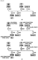
- FIG. 11 illustrates a non-failure-section power source system using a distributed power source 40 in the related art.
- the non-failure-section power source system using the distributed power source 40 includes an IED 100 for power distribution automation, an IED 200 for distributed power source, and a central management device 300.
- the IED 100 for power distribution automation measures the voltage and current of the power distribution line, and when a failure occurs in the power distribution grid, the event of the failure of the line is transmitted to the central management device 300, so that an operator of the power distribution automation system can be allowed to analyze the failure.
- the IED 100 for power distribution automation determines based on the failure current whether or not there is a failure in the power distribution grid or determines the direction of the failure current. In a case where it is determined that there is a failure, the IED 100 transmits FI (fault indicator) information to the central management device 300.
- FI fault indicator
- the central management device 300 determines a failure section from the failure information provided from the IEDs 100 for power distribution automation and transmits an operation command of the switch 30 to the IED 100 for power distribution automation.
- the IED 100 for power distribution automation performs the control of the switch 30 and, after that, transmits the result of the control to the central management device 300 to perform the failure management procedure.
- the IED 100 for power distribution automation measures an overcurrent of the power distribution line, blocks the line through a protection device 20 of a circuit breaker or a recloser.
- the failure of the power distribution line is detected through the switch.
- the central management device 300 controls the closing and opening of the switch based on a control signal of the central management device 300 to perform a function of controlling the failure section to be separated from the power distribution grid.
- the IED 100 for power distribution automation transmits failure occurrence information to the IED 200 for the distributed power source, so that the IED 200 for the distributed power source can be allowed to supply power to the non-failure section through the distributed power source 40.
- the IED 100 for power distribution automation performs a function of measuring an average load current with respect to the load stage existing between the distributed power source 40 and the IED 100 for power distribution automation.
- the average load current can be calculated by measuring the load current with respect to the load stage for a predetermined period of time.
- the average power consumption consumed by the load stage each time of day can be calculated.
- the information calculated by the IED 100 for power distribution automation is transmitted to the IED 200 for distributed power source and can be utilized as data for calculating the amount of power to be supplied through the distributed power source 40 when a failure occurs in the power distribution grid.
- the IED 200 for distributed power source is connected to a distributed power source 40 and calculates the amount of power that the distributed power source 40 can supply to the grid when there is a failure in the power distribution grid.
- the IED 200 for distributed power source can calculate the amount of power based on the power generation amount of the distributed power source 40 and the battery storage amount.
- the IED 200 for distributed power source is connected to the IED 100 for power distribution automation in a peer to peer manner to check the amount of power consumed in the power distribution line connected to the distributed power source 40 and receives the failure occurrence information from the IED 100 for power distribution automation.
- failure occurrence information and the failure current information are received from the IED 100 for power distribution automation, a non-failure section in which a power failure is unnecessarily experienced due to the failure is identified, so that power can be supplied to the non-failure section by controlling the switch between the distributed power source 40 and the grid.
- the IED 200 for distributed power source analyzes the information on the failure occurrence and the information on the failure current included in the failure information to identify the failure section or to identify the failure occurrence section through the identification information of the IED 100 for power distribution automation for transmitting the failure information.
- the central management device 300 monitors the entire system and analyzes the received failure information of the power distribution grid from the IED 100 for power distribution automation to perform a function of controlling the closing and opening of the switch 30.
- the central management device 300 analyzes the failure information and transmits a signal of controlling the closing and opening of the switch 30 to the IED 100 for power distribution automation, so that the failed line can be allowed to be separated from the grid.
- the microgrid system illustrated in FIG. 11 has an IED for each distributed power source and distributed load (power distribution).
- Each IED requires a relatively large test power to accurately identify a failure when the failure occurs.
- each IED needs to have a relatively large capacity of energy storage device or a diesel generator for production of the test power, which inevitably causes an increase in equipment costs.
- the present invention is to provide a microgrid or a failure management method that can quickly identify and manage a failure position. More specifically, the present invention is to provide a method of identifying a position of a failure using an ESS, separating the failure point, and reconstructing power transmission when the failure occurs in a line or a device in off-grid.
- the present invention is to improve reliability by performing a stable grid operation in a microgrid.
- an SS PCS is allowed to quickly identify the failure point and separate the failure point.
- a microgrid system having a plurality of distributed power sources; a plurality of distributed loads; and lines for connecting the distributed power sources and the distributed loads
- the microgrid system including: an ESS for storing power supplied from all or a portion of the distributed power sources and supplying the stored power to all or a portion of the distributed loads; an ESS PCS including an interruption means for converting the power stored in the ESS into AC power suitable for the microgrid and supplying the AC power to the microgrid in order to block connection to the microgrid in an abnormal state; and a monitoring/control device for gradually increasing a voltage output from the ESS PCS and performing processing for the failure when a failure is detected in the microgrid.
- the monitoring/control device may perform steps of: blocking the distributed power source and the ESS when a failure is detected in the microgrid; connecting the ESS PCS to the microgrid; gradually increasing the voltage output from the connected ESS PCS and determining a position where the failure occurred; and blocking the position where the failure occurred and connecting the distributed power source to the microgrid.
- the interruption means may include: a DC-stage switch for interrupting a battery and an inverter of the ESS; an AC-stage switch for interrupting the inverter of the ESS PCS and the microgrid; and an IGBT interruption means for interrupting an IGBT constituting the inverter.
- an open time of an IGBT constituting an inverter of the ESS PCS may be within 400 [ ⁇ s]
- a time for gradually increasing the voltage output from the ESS PCS may be a period of time specified in a range of 1 second to 3 seconds.
- the monitoring/control device may include a communication means capable of communicating data with a detection/measurement means installed in the distributed power sources, the distributed loads, and the lines.
- the monitoring/control device may gradually increase the current from 0 [A] to a level of 80% of a rated current that can be output to the microgrid for a specified period of time in order to gradually increase the voltage output from the ESS PCS.
- a failure management method for a microgrid system having: a plurality of distributed power sources; a plurality of distributed loads; lines for connecting the distributed power sources and the distributed loads; and an ESS for storing power supplied from all or a portion of the distributed power sources and supplying the stored power to all or a portion of the distributed loads
- the failure management method including steps of: blocking the distributed power source and the ESS when a failure is detected in the microgrid system; connecting a PCS of the ESS to the microgrid; gradually increasing a voltage output in the PCS of the ESS and determining a position where the failure occurred; and blocking the position where the failure occurred and connecting the distributed power source to the microgrid.
- the step of connecting the PCS of the ESS to the microgrid may include steps of: closing a DC-stage switch for interrupting a battery and an inverter of the ESS; closing an AC-stage switch for interrupting the inverter of the ESS and the microgrid; and closing the IGBT constituting the inverter.
- a trend of current change with the gradual increase of the voltage may be compared with a trend of current change in a normal state, and if there is checked an increasing trend in which the trend of current change is significantly higher than the trend of current change in the normal state, it may be determined that there is a failure in a line/load side.
- the current in the step of determining the position where the failure has occurred, may be gradually increased from 0 [A] to a level of 80% of a rated current that can be output to the microgrid for a specified period of time in order to gradually increase the voltage output from the ESS PCS.
- microgrid system according to the present invention has an advantage in that it is not necessary to install a separate diesel generator or to provide a large capacity battery for each distributed power source for a failure test.
- the microgrid system according to the present invention has an advantage of minimizing a power generation amount of a new renewable source discarded by a power failure.
- the microgrid system according to the present invention has an advantage of being easily maintained and managed in a microsystem of a remote area such as islands constituting a stand-alone grid without connection to independent external power systems and being suitable for long current supply application.
- first, second, and the like may be used to describe various components, but the components may not be limited by the terms. The terms are used only for the purpose of distinguishing one component from the others.
- a first component may be referred to as a second component, and similarly, a second component may also be referred to as a first component.
- a component In a case where a component is referred to as being connected to or coupled with another component, the component may be directly connected to or coupled with another component, but it may be understood that still another component may exist between the components.
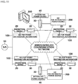
- FIG. 1 is a block diagram illustrating a microgrid system 700 according to the present invention.
- the illustrated microgrid system 700 includes: a plurality of distributed power sources 740 and 750 supplying power to a grid; a plurality of distributed loads 771, 772, and 773 consuming the power in the grid; lines for connecting the distributed power sources 740 and 750 and the distributed loads 771, 772, and 773 to the grid; and an ESS 720 storing the power from all or a portion of the distributed power sources 740 and 750 and supplying the stored power to all or a portion of the distributed loads 771, 772, and 773.
- the microgrid system 700 may include interruption means 781 to 788 capable of selectively connecting or blocking each of all or a portion of the plurality of distributed power sources 740 and 750 and the distributed loads 771 772 and 773 to the grid.
- the lines need to have ideally identical electrical characteristics (potentials) for the distributed power sources 740 and 750 and the distributed loads 771, 772, and 773 connected to the grid.
- the respective points of the lines have different electrical characteristics (potentials, currents) due to the unbalance of the supplied power and/or the load and the impedance of the long lines.
- detection/measurement means 781 to 785 may be provided at specific points of the lines.
- the detection/measurement means may be provided at each connection point of the distributed power sources 740 and 750 and the distributed loads 771, 772, and 773, or the detection/measurement means may be provided in units of a predetermined length.
- each of all or a portion of the plurality of distributed power sources 740 and 750 and the distributed loads 771, 772, and 773 may include a detection/measurement means or a monitoring means for monitoring their own operational states and/or electrical characteristics.
- the ESS 720 has a configuration for reducing the power burden due to uneven load demands in the microgrid. Recently, for the ESS 720, a method using a lithium secondary battery has been used, but a known energy storage means may be applied.
- the plurality of distributed power sources 740 and 750 also include respective PCSs 745 and 755, and the plurality of distributed loads 771 and 772 and 773 also include respective interruption means 786 to 788.
- the functions according to the present invention are implemented by using a PCS 730 of the ESS 720 and an interruption means 781 for connecting/blocking the PCS 730 to the grid.
- the PCS 730 and the interruption means 781 for the ESS 720 will be described more in detail.
- the PCS 730 for the ESS 720 may be referred to as an ESS PCS 730 and includes an interruption means 781 which converts the power stored in the ESS 720 into AC (or DC) power suitable for the microgrid to supply the power to the microgrid or to interrupt connection to the microgrid in an abnormal situation such as a power failure or a short circuit.
- the ESS PCS 730 can perform a power phase synchronization function for matching the power phase of the grid with the power phase of the power output from the PCS to the grid, a function of adjusting the amount of power (that is, magnitudes of the voltage and/or the current) supplied to the grid, and a surge reduction/protection function for reducing and/or blocking transfer of risk factors such as a surge occurring in the grid side to the ESS 720 and can has a configuration for these functions. Since the above-described functions are known in the ESS field, detailed description thereof is omitted.
- the ESS PCS 730 may be separated from the grid for a while.
- the opening time of an IGBT (more specifically, an IGBT constituting the inverter) included in the ESS PCS 730 is advantageously within about several hundred microseconds ( ⁇ s).
- the ESS PCS 730 that is capable of adjusting the amount of power with a continuous value, if possible, is advantageous in the function of adjusting the amount of power supplied to the grid. Even in a case where the amount of power is adjusted stepwise in a discontinuous manner, the steps that are set to be detailed are advantageous if possible.
- the illustrated ESS PCS 730 can gradually the current from 0 [A] to a level (if not a failure) of 80% of the maximum current (rated current) that can be output to the grid during a predetermined test time (for example, a period of time specified in a range of 1 second to 3 seconds) at the starting time.
- the ESS PCS 730 can adjust the amount of power output to the grid according to the connection state of the plurality of distributed power sources 740 and 750 and the plurality of distributed loads 771, 772, and 773 for the grid in the microgrid system. This can be implemented by applying the ESS technology and/or the PCS technology for configuring a known smart grid system.
- the process of gradually increasing the output voltage for a predetermined period of time (for example, a period of time specified in a range of 1 second to 3 seconds) in the above-described ESS PCS can be performed by a method of connecting the ESS, which has been separated from the grid, to the grid again and sequentially increasing the voltage from 0 V at the beginning of the connection to a predetermined voltage level for a predetermined period of time (for example, a period of time specified in a range of 1 second to 3 seconds).
- a predetermined voltage level for a predetermined period of time for example, a period of time specified in a range of 1 second to 3 seconds.
- the relationship between the time and the voltage forms a continuous linear function (a straight line with a predetermined slope).
- the relationship between the time and the voltage may have characteristics of discrete and/or curved lines.
- the reference point of the voltage and current measurement is preferably the output stage (connection point with the grid) of the ESS PCS, but the reference point is not limited thereto.
- a general ESS PCS function in the related art can be used as a method of gradually increasing the output voltage for a predetermined period of time in the ESS PCS.
- the number of cells used for generating an output power among buffered battery cells can be sequentially increased.
- the output voltage can be adjusting in such a manner that the capacity and/or the number of unit cells of the temporary energy storage means are adjusted.
- a transformer having a multi-stage tap capable of discretely increasing the output voltage level can be used.
- the microgrid system 700 may include a monitoring/control device 760 determining a position where a failure has occurred in the microgrid system by using the ESS PCS 730 and performing black start as a follow-up measures to the failure.
- the monitoring/control device 760 is advantageously provided at a centralized control site of the microgrid system 700. In order to actively utilize the ESS 720 and the ESS PCS 730, the monitoring/control device 760 is advantageously located at or close to the same site (place) as the ESS 720.
- the monitoring/control device 760 can communicate data (signals) with the detection/measurement means 791 to 795 or the monitoring means provided on the ESS 720, the ESS PCS 730, the distributed power sources 740 and 750, and the distributed loads 771, 772, and 773, and the lines.
- the monitoring/control device 760 may include a power line communication means capable of accessing each detection/measurement means or monitoring means or a wired/wireless communication means using a separate power line and an independent medium.
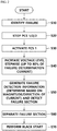
- FIG. 2 is a flowchart illustrating a failure management method performed in the monitoring/control device 760 of FIG. 1 .
- the illustrated failure management method includes: a failure detection step S10 of detecting a failure in the microgrid system; a grid interruption step S20 of blocking the distributed power sources and the ESS; a step S30 of connecting the ESS PCS to the microgrid system; a step S40 of gradually increasing the voltage output from the connected ESS PCS and a step S50 of determining the position where the failure has occurred (S50); and a step S60 of blocking the position where the failure has occurred and a step S70 of connecting the distributed power sources to the microgrid.
- the failure detection step S10 may be performed in the PCSs of the distributed power sources and the ESS connected to the microgrid. That is, each PCS can detect the failure occurring in the microgrid system by a self-protection function to protect the distributed power source or the ESS that mediates with the grid. The PCS that has detected the failure can report the failure to the monitoring/control device by using a data communication means.
- the grid interruption step S20 can be performed by a function of the PCS. In a case where the PCS cannot detect the failure, the grid interruption step S20 can be performed by an interrupt command of the monitoring/control device that has received the failure report.
- the step S60 is for separating a section determined as a failure in the step S50 from the grid. More specifically, the failure section can be blocked by turning off the interruption means of the distributed power source or the distributed load which is determined that there is a failure.
- the step S70 is a step of restarting the microgrid in a state where only the failure section is separated from the grid before the failure is completely recovered in the failure state, which may be referred to as a black start. If it is checked in the step S70 that the failure section of the grid is separated (S60), first, the ESS PCS is connected to the microgrid system to supply power to the non-failure section, and the PCS of the blocked distributed power sources (PV/WT) can be sequentially connected to the microgrid.
- PV/WT blocked distributed power sources
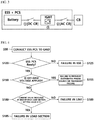
- FIG. 3 illustrates an embodiment of a connection structure of the ESS PCS to the microgrid, which can be applied to perform the steps S20 and S30.
- the interruption means may include a DC-stage switch DC CB for interrupting the battery of the ESS and the PCS inverter; an AC-stage switch AC CB for interrupting an inverter of the ESS PCS and the microgrid; and an IGBT interruption means (not illustrated) for interrupting the IGBT constituting the inverter.
- the battery of the ESS is interrupted with the inverter by the DC-stage switch DC CB, and the inverter can be interrupted with the ESS interruption means (CB, 781 in FIG. 1 ) or the microgrid by the AC-stage switch AC CB again.
- the order in which the ESS PCS separated from the grid due to the failure occurring in the grid are connected to the grid again according to the present invention is that, first, the DC-stage switch DC CB is closed, next, the AC-stage switch (AC CB) is closed, and next, the IGBT constituting the inverter is closed according to the DC-AC conversion operation.
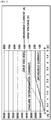
- Table 1 below describes criteria of the failure position determination performed in the failure position determination step S50.
- Failure in ESS It is determined whether or not an ESS PCS operates (in case of a failure, the ESS PCS does not operate) Failure or Temporary Failure in Installed Distributed Power Source Off-grid voltage application is possible. (It is determined that there is no failure section in the voltage-applied grid) -> Distributed power sources are sequentially connected.
- FIG. 4 is a flowchart illustrating an example of a failure position determination method performed in the failure position determination step S50.
- the illustrated failure position determination method may include: a step S120 of checking whether or not the ESS PCS is in a normal operation when the ESS PCS is connected to the grid (S30); a step S150 of gradually increasing the voltage supplied to the grid in the ESS PCS, monitoring the current of the microgrid, and checking whether or not there a failure in a line/load side, if it is checked that the ESS PCS is in a normal operation; a step S180 of checking whether or not there is a failure in each of load sections if it is checked that there is a failure in the line/load side; and a step 189 of checking whether or not there is a failure in a line if it is not checked that there is a failure in each load section.
- the flowchart illustrated in FIG. 2 is executed by performing the step S30 of connecting the ESS PCS to the microgrid in FIG. 2 , and the step S30 in the figure denotes the step S30 in FIG. 2 .
- the ESS PCS or the ESS does not operate normally in the step S120 of checking whether or not the PCS normally operates, it is determined that there is a failure in the ESS, and the procedure is ended.
- the checking whether or not the ESS PCS normally operates is a general technique in the ESS PCS, and thus, detailed description thereof is omitted.
- a step of checking whether or not power enough to perform gradual voltage application (off-grid voltage application) to the grid according to the present invention is stored in the ESS may be further included. This is due to the considerable power required for the gradual voltage application to the grid in order to check whether or not there is a failure in the entire grid.
- step S150 of checking whether or not a failure occurs in the line/load side the increasing the voltage/current to be supplied to the grid in the ESS PCS denotes performing the step S40 of FIG. 2 .
- FIG. 5 is a graph illustrating a relationship between the voltage and the current measured for the off-grid voltage application in the normal state.
- FIG. 6 is a graph illustrating the voltage and the current measured for the off-grid voltage application in a state where there is a failure in the microgrid.
- the grid voltage is 380 [V]
- the total load is 1.5 [M]
- the ESS PCS capacity is 2.0 [M].
- the failure determination current is a reference current amount sufficient to determine a failure, and the failure determination current may be an amount of current that does not interfere with evenly distributing power to the line/load side connected to the grid.
- the maximum current (rated current) that can be output to the grid to which the line/load side is connected in the ESS PCS is applicable.
- step S30 in FIG. 2 since the distributed power source is not connected, it can be determined that the failure is not caused by the distributed power source.
- step S150 If it is checked in the step S150 that the off-grid voltage application can be performed, it is determined that there is no failure section in the voltage-applied grid (the section connected to the grid in the step S30), and in the step S155, it can be checked whether or not the installed distributed power source can be sequentially connected and has a failure. For example, due to the connected distributed power source, if a power failure occurs again, it can be determined that there is a failure caused by the distributed power source.
- the fact that the off-grid voltage application can be performed denotes that the voltage-current pattern according to the graph illustrated in FIG. 5 appears.
- step S150 If the off-grid voltage application is not properly performed in the step S150, operations after step S180 of measuring the magnitude and direction of the current of the line section and the load side are performed.
- the current value measured at the end stage of each load section is compared with a predetermined setting value, and in a case where the current value falls below a predetermined ratio, it is determined that there is a failure in the load section.
- the current value measured at the end stage of each load section is compared with a setting value to determine the failure section. For example, if measured value > setting value x 0.5 (variable), it can be determined that there is a failure in the corresponding section.
- the multiplication factor can be adjusted according to the capacity or the like of the ESS.
- the difference in magnitude between the currents before and after measurement can be estimated as the current flowing in the failure point.
- the currents before and after measurement are similar.
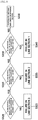
- FIG. 7 is a flowchart illustrating a more detailed process of sequentially connecting the distributed power sources installed in the microgrid and checking whether or not a failure has occurred in the step S155 of FIG. 4 .
- FIG. 7 illustrates sequential connection of the installed distributed power sources for post-failure checking, and it is assumed that there are only a solar power source (PV) and a wind power source (WT) as the distributed power source separated from the microgrid due to the failure.
- PV solar power source
- WT wind power source
- the illustrated distributed power source checking method may include: a step S210 of connecting the PCS of the wind power source WT to the grid; a step S220 of checking whether or not a power failure occurs; a step S230 of connecting the PCS of the solar power source (PV) to the grid if the power failure by the wind power source (WT) does not occur; a step S240 of checking whether or not a power failure occurs; and a step S250 of determining that there is a temporary failure if the power failure by the solar power source PV does not occur.
- step S220 If it is checked in the step S220 that the power failure has occurred, it can be determined that there is a failure in the line of the wind power source WT (S225). If it is checked in the step S240 that the power failure has occurred, it can be determined that there is a failure in the line of the solar power PV (S245).
- the wind power source WT is checked, and then the PV power is checked.
- the checking order may be changed.
- FIG. 8 is a flowchart illustrating a more detailed process of checking whether or not there is a failure in the line sections in the step S189 of FIG. 4 . In the figure, it is assumed that there are only line sections 1, 2, and 3.
- the illustrated line section checking method may include: a step S320 of checking whether or not the magnitude of the current before measurement of the line section 3 is similar to the magnitude of the current after measurement (which denotes that the magnitudes of the currents belong to the same range in practical terms); a step S330 of checking whether or not the magnitude of the current before measurement of the line section 2 is similar to the magnitude of the current after measurement if the magnitudes of the currents before and after measurement of the line section 3 are similar to each other; a step S330 of checking whether or not the magnitude of the current before measurement of the line section 1 is similar to the magnitude of the current after measurement if the magnitudes of the currents before and after measurement of the line section 2 are similar to each other; and a step S350 of performing the re-checking and/or checking the exceptional section (excluded section) if the magnitudes of the currents before and after measurement of the line section 1 are similar to each other.
- step S320 If it is checked in the step S320 that the magnitudes of the currents before and after measurement are different from each other, it can be determined that there is a failure in the line section 3 (S325). If it is checked in the step S330 that the magnitudes of the currents before and after measurement are different from each other, it can be determined that there is a failure in the line section 2 (S335). If it is checked in the step S340 that the magnitudes of the currents before and after measurement are different from each other, it can be determined that there is a failure in the line section 1 (S345).
- FIGS. 9(a) to 9(c) are block diagrams illustrating operations from the occurrence of a failure to a black start in the microgrid system according to the present invention.
- the ESS including the PCS and each distributed power source (PV, WT) are blocked from the microgrid by the interruption means (CB: circuit breaker) and/or the PCS self protection function.
- FIG. 9(c) illustrating a state in which the failure management according to the present invention is performed
- the distributed power sources (PV, WT) are blocked from the grid as they are
- the ESS PCS is connected to the microgrid, and by activating the ESS, the voltage of the grid is allowed to be gradually increased.
- FIG. 10 illustrates the voltage and current waveforms of the ESS PCS according to the gradual step-up start (soft Start) according to the present invention.
- the figure illustrates, as the soft start function of the PCS for battery, the voltage and current waveforms of the ESS output stage as the gradual increase of the output voltage from 0 V to the rated voltage for about 1 second.
- the soft start operation of the ESS PCS described above can be connected to the black start, which blocks the failure portion in the grid and activates the microgrid again.
- functions of a VCB-side UVR relay are required to deactivated during the black start, and after the deactivation of the UVR relay, by operating all the circuit breakers, the ESS PCS is required to be activated.
- the present invention relating to a microgrid system for performing failure management and a failure management method using the microgrid system can be used in a power system field.
Landscapes
- Engineering & Computer Science (AREA)
- Power Engineering (AREA)
- Physics & Mathematics (AREA)
- General Physics & Mathematics (AREA)
- Business, Economics & Management (AREA)
- Emergency Management (AREA)
- Supply And Distribution Of Alternating Current (AREA)
Applications Claiming Priority (2)
| Application Number | Priority Date | Filing Date | Title |
|---|---|---|---|
| KR1020160167910A KR101943468B1 (ko) | 2016-12-09 | 2016-12-09 | 마이크로그리드 시스템 및 고장 처리 방법 |
| PCT/KR2017/014140 WO2018105989A1 (ko) | 2016-12-09 | 2017-12-05 | 마이크로그리드 시스템 및 고장 처리 방법 |
Publications (3)
| Publication Number | Publication Date |
|---|---|
| EP3553911A1 true EP3553911A1 (de) | 2019-10-16 |
| EP3553911A4 EP3553911A4 (de) | 2020-05-06 |
| EP3553911B1 EP3553911B1 (de) | 2022-01-05 |
Family
ID=62491932
Family Applications (1)
| Application Number | Title | Priority Date | Filing Date |
|---|---|---|---|
| EP17877559.9A Active EP3553911B1 (de) | 2016-12-09 | 2017-12-05 | Mikronetzsystem und verfahren zur verwaltung von fehlfunktionen |
Country Status (5)
| Country | Link |
|---|---|
| US (1) | US10998756B2 (de) |
| EP (1) | EP3553911B1 (de) |
| KR (1) | KR101943468B1 (de) |
| AU (1) | AU2017371146A1 (de) |
| WO (1) | WO2018105989A1 (de) |
Cited By (1)
| Publication number | Priority date | Publication date | Assignee | Title |
|---|---|---|---|---|
| CN110854889A (zh) * | 2019-10-28 | 2020-02-28 | 江西赣锋电池科技有限公司 | 一种储能系统及其多级保护方法 |
Families Citing this family (14)
| Publication number | Priority date | Publication date | Assignee | Title |
|---|---|---|---|---|
| CN109995070A (zh) * | 2017-12-29 | 2019-07-09 | 西门子公司 | 微电网系统 |
| CN110120657B (zh) * | 2018-02-06 | 2022-04-08 | 西门子公司 | 单元电网保护装置、大电网以及控制单元电网保护装置的方法 |
| US11616390B2 (en) * | 2018-06-19 | 2023-03-28 | Tsinghua University | Micro-grid reconstruction method and device, micro-grid protection control center, and storage medium |
| EP3605776B1 (de) * | 2018-07-31 | 2022-04-20 | Schneider Electric Industries SAS | Verfahren zum orten von phasenfehlern in einem microgrid |
| CN109066785B (zh) * | 2018-08-23 | 2022-06-07 | 上海电气分布式能源科技有限公司 | 一种微电网实时控制方法及微电网 |
| US11239659B2 (en) * | 2019-06-10 | 2022-02-01 | Schweitzer Engineering Laboratories, Inc. | Microgrid autosynchronizing using remote recloser inputs and outputs |
| KR20210016795A (ko) | 2019-08-05 | 2021-02-17 | 주식회사 엘지화학 | 에너지 허브 장치 및 에너지 관리 방법 |
| CN110994571B (zh) * | 2019-12-17 | 2021-09-07 | 东北电力大学 | 一种适用交直流混合配电网的故障分级处理方法 |
| US11588323B2 (en) * | 2020-09-03 | 2023-02-21 | Commonwealth Associates, Inc. | Method and apparatus for locating faults in an islanded microgrid |
| CN111948494B (zh) * | 2020-09-10 | 2024-12-10 | 湖南科技大学 | 一种便捷式微电网故障检测装置及其检测方法 |
| CN112953011A (zh) * | 2021-03-05 | 2021-06-11 | 深圳供电局有限公司 | 一种基于自主可控微网和分布式电源并网接口装置的智慧能源电力终端系统 |
| US11929608B2 (en) | 2021-09-01 | 2024-03-12 | Schweitzer Engineering Laboratories, Inc. | Systems and methods for operating an islanded distribution substation using inverter power generation |
| CN113922405B (zh) * | 2021-10-29 | 2024-08-13 | 阳光电源股份有限公司 | 一种多级式储能系统及其控制方法 |
| FI20235981A1 (en) * | 2023-09-01 | 2025-03-02 | Elisa Oyj | Computer-implemented method for managing a site of a virtual power plant |
Family Cites Families (13)
| Publication number | Priority date | Publication date | Assignee | Title |
|---|---|---|---|---|
| JP4213941B2 (ja) | 2002-10-11 | 2009-01-28 | シャープ株式会社 | 複数の分散電源の出力抑制方法および分散電源管理システム |
| KR100934162B1 (ko) | 2008-04-08 | 2010-01-06 | 주식회사 투윈스컴 | 씨씨티브이용 디지털 비디오 레코더 |
| KR101097458B1 (ko) * | 2009-11-09 | 2011-12-23 | 한국전기연구원 | 마이크로그리드 시스템 및 정지형 스위치의 부하제어 방법 |
| JP2012020991A (ja) | 2010-06-16 | 2012-02-02 | Takasago Internatl Corp | 経皮吸収促進剤、及びこれを含有する皮膚外用製剤 |
| KR101266953B1 (ko) | 2011-02-23 | 2013-05-30 | 한전케이디엔주식회사 | 분산전원을 이용한 건전구간 전원공급 시스템 및 방법 |
| KR101869756B1 (ko) | 2012-04-12 | 2018-06-21 | 주식회사 케이엠더블유 | 이동통신 시스템용 가변 빔 제어 안테나 |
| KR101382478B1 (ko) * | 2012-05-23 | 2014-04-08 | 연세대학교 산학협력단 | 전력 계통 변화에 대응하는 적응 보호 과전류 제어 시스템 및 방법 |
| US9620994B2 (en) * | 2013-01-17 | 2017-04-11 | Eaton Corporation | Method and system of anti-islanding of a microgrid in a grid-connected microgrid system |
| KR101336042B1 (ko) * | 2013-08-19 | 2013-12-03 | 주식회사 나산전기산업 | 태양광발전 시스템을 갖는 비상 전원 시스템 |
| KR101571213B1 (ko) * | 2013-09-27 | 2015-11-24 | 한국전력공사 | 고장처리장치를 구비하는 마이크로그리드 시스템 및 그 동작 방법 |
| KR101514999B1 (ko) | 2013-10-29 | 2015-04-24 | 남서울대학교 산학협력단 | 배전계통에서 스마트 보호기기를 이용한 자율적 고장구간 확인 및 분리 방법 및 그 시스템 |
| US20160190822A1 (en) * | 2014-12-30 | 2016-06-30 | Lg Cns Co., Ltd. | Microgrid energy management system and power storage method for energy storage system |
| US10418916B2 (en) * | 2015-12-23 | 2019-09-17 | Daming Zhang | Circuits of voltage source DC/AC converter with LCCL or LCC filter and other modified forms, and operation of microgrid with such circuits |
-
2016
- 2016-12-09 KR KR1020160167910A patent/KR101943468B1/ko active Active
-
2017
- 2017-12-05 AU AU2017371146A patent/AU2017371146A1/en not_active Abandoned
- 2017-12-05 US US16/467,074 patent/US10998756B2/en active Active
- 2017-12-05 WO PCT/KR2017/014140 patent/WO2018105989A1/ko not_active Ceased
- 2017-12-05 EP EP17877559.9A patent/EP3553911B1/de active Active
Cited By (1)
| Publication number | Priority date | Publication date | Assignee | Title |
|---|---|---|---|---|
| CN110854889A (zh) * | 2019-10-28 | 2020-02-28 | 江西赣锋电池科技有限公司 | 一种储能系统及其多级保护方法 |
Also Published As
| Publication number | Publication date |
|---|---|
| KR101943468B1 (ko) | 2019-01-29 |
| US20190319481A1 (en) | 2019-10-17 |
| EP3553911B1 (de) | 2022-01-05 |
| AU2017371146A1 (en) | 2019-07-25 |
| WO2018105989A1 (ko) | 2018-06-14 |
| US10998756B2 (en) | 2021-05-04 |
| EP3553911A4 (de) | 2020-05-06 |
| KR20180066732A (ko) | 2018-06-19 |
Similar Documents
| Publication | Publication Date | Title |
|---|---|---|
| EP3553911B1 (de) | Mikronetzsystem und verfahren zur verwaltung von fehlfunktionen | |
| AU2017202918B2 (en) | Management of battery capacity | |
| KR101904815B1 (ko) | Ess용 pcs 및 pcs 운전 방법 | |
| EP3605776A1 (de) | Verfahren zur ortung von phasenfehlern in einem mikronetz | |
| KR20140060401A (ko) | 독립형 마이크로그리드 제어 시스템 및 그 제어방법 | |
| EP3334000B1 (de) | Verfahren zur steuerung eines stromverteilungsmikronetzes | |
| US10033194B2 (en) | Intelligent electrical power network device | |
| KR101904821B1 (ko) | 마이크로그리드 시스템 및 고장 처리 방법 | |
| US20250237690A1 (en) | Insulation state detection method, system, and apparatus, storage medium, and program product | |
| US20250202241A1 (en) | Control apparatus used in microgrid system, control method, and microgrid system | |
| CN114221377B (zh) | 一种并离网多储能响应控制方法及系统 | |
| CA3060181C (en) | Method for detecting formation of a separate system | |
| US12424852B2 (en) | Electrical assembly with a dynamic braking system | |
| KR101034251B1 (ko) | 계통연계형 분산전원의 병렬운전에서의 독립운전을 판단하는 시스템 및 이를 이용한 독립운전 판단 방법. | |
| AU2020455288B2 (en) | Method, apparatus, and system for monitoring islanding electricity generation unit | |
| CN112993947A (zh) | 一种网络式频率电压紧急控制方法、装置及系统 | |
| KR20200104065A (ko) | 수용가 전력 장애 자동 복구를 위한 스마트 전력 스위칭 방법 | |
| KR20170132534A (ko) | 고장 파급 방지 시스템 | |
| TW201715821A (zh) | 分散式頻率偵測及防止微電網全黑控制器 |
Legal Events
| Date | Code | Title | Description |
|---|---|---|---|
| STAA | Information on the status of an ep patent application or granted ep patent |
Free format text: STATUS: THE INTERNATIONAL PUBLICATION HAS BEEN MADE |
|
| PUAI | Public reference made under article 153(3) epc to a published international application that has entered the european phase |
Free format text: ORIGINAL CODE: 0009012 |
|
| STAA | Information on the status of an ep patent application or granted ep patent |
Free format text: STATUS: REQUEST FOR EXAMINATION WAS MADE |
|
| 17P | Request for examination filed |
Effective date: 20190702 |
|
| AK | Designated contracting states |
Kind code of ref document: A1 Designated state(s): AL AT BE BG CH CY CZ DE DK EE ES FI FR GB GR HR HU IE IS IT LI LT LU LV MC MK MT NL NO PL PT RO RS SE SI SK SM TR |
|
| AX | Request for extension of the european patent |
Extension state: BA ME |
|
| DAV | Request for validation of the european patent (deleted) | ||
| DAX | Request for extension of the european patent (deleted) | ||
| A4 | Supplementary search report drawn up and despatched |
Effective date: 20200406 |
|
| RIC1 | Information provided on ipc code assigned before grant |
Ipc: H02J 9/06 20060101ALN20200331BHEP Ipc: H02J 13/00 20060101ALI20200331BHEP Ipc: H02J 3/32 20060101ALI20200331BHEP Ipc: H02J 3/38 20060101AFI20200331BHEP Ipc: H02J 3/00 20060101ALI20200331BHEP Ipc: H02H 7/26 20060101ALI20200331BHEP Ipc: G01R 31/08 20200101ALI20200331BHEP |
|
| GRAP | Despatch of communication of intention to grant a patent |
Free format text: ORIGINAL CODE: EPIDOSNIGR1 |
|
| STAA | Information on the status of an ep patent application or granted ep patent |
Free format text: STATUS: GRANT OF PATENT IS INTENDED |
|
| RIC1 | Information provided on ipc code assigned before grant |
Ipc: H02J 3/38 20060101AFI20210528BHEP Ipc: H02H 7/26 20060101ALI20210528BHEP Ipc: H02J 3/32 20060101ALI20210528BHEP Ipc: G01R 31/08 20200101ALI20210528BHEP Ipc: H02J 3/00 20060101ALI20210528BHEP Ipc: H02J 13/00 20060101ALI20210528BHEP Ipc: H02J 9/06 20060101ALN20210528BHEP |
|
| RIC1 | Information provided on ipc code assigned before grant |
Ipc: H02J 3/38 20060101AFI20210615BHEP Ipc: H02H 7/26 20060101ALI20210615BHEP Ipc: H02J 3/32 20060101ALI20210615BHEP Ipc: G01R 31/08 20200101ALI20210615BHEP Ipc: H02J 3/00 20060101ALI20210615BHEP Ipc: H02J 13/00 20060101ALI20210615BHEP Ipc: H02J 9/06 20060101ALN20210615BHEP |
|
| INTG | Intention to grant announced |
Effective date: 20210702 |
|
| GRAS | Grant fee paid |
Free format text: ORIGINAL CODE: EPIDOSNIGR3 |
|
| GRAA | (expected) grant |
Free format text: ORIGINAL CODE: 0009210 |
|
| STAA | Information on the status of an ep patent application or granted ep patent |
Free format text: STATUS: THE PATENT HAS BEEN GRANTED |
|
| AK | Designated contracting states |
Kind code of ref document: B1 Designated state(s): AL AT BE BG CH CY CZ DE DK EE ES FI FR GB GR HR HU IE IS IT LI LT LU LV MC MK MT NL NO PL PT RO RS SE SI SK SM TR |
|
| REG | Reference to a national code |
Ref country code: GB Ref legal event code: FG4D |
|
| REG | Reference to a national code |
Ref country code: CH Ref legal event code: EP |
|
| REG | Reference to a national code |
Ref country code: AT Ref legal event code: REF Ref document number: 1461444 Country of ref document: AT Kind code of ref document: T Effective date: 20220115 |
|
| REG | Reference to a national code |
Ref country code: DE Ref legal event code: R096 Ref document number: 602017052096 Country of ref document: DE |
|
| REG | Reference to a national code |
Ref country code: IE Ref legal event code: FG4D |
|
| REG | Reference to a national code |
Ref country code: LT Ref legal event code: MG9D |
|
| REG | Reference to a national code |
Ref country code: NL Ref legal event code: MP Effective date: 20220105 |
|
| REG | Reference to a national code |
Ref country code: AT Ref legal event code: MK05 Ref document number: 1461444 Country of ref document: AT Kind code of ref document: T Effective date: 20220105 |
|
| PG25 | Lapsed in a contracting state [announced via postgrant information from national office to epo] |
Ref country code: NL Free format text: LAPSE BECAUSE OF FAILURE TO SUBMIT A TRANSLATION OF THE DESCRIPTION OR TO PAY THE FEE WITHIN THE PRESCRIBED TIME-LIMIT Effective date: 20220105 |
|
| PG25 | Lapsed in a contracting state [announced via postgrant information from national office to epo] |
Ref country code: SE Free format text: LAPSE BECAUSE OF FAILURE TO SUBMIT A TRANSLATION OF THE DESCRIPTION OR TO PAY THE FEE WITHIN THE PRESCRIBED TIME-LIMIT Effective date: 20220105 Ref country code: RS Free format text: LAPSE BECAUSE OF FAILURE TO SUBMIT A TRANSLATION OF THE DESCRIPTION OR TO PAY THE FEE WITHIN THE PRESCRIBED TIME-LIMIT Effective date: 20220105 Ref country code: PT Free format text: LAPSE BECAUSE OF FAILURE TO SUBMIT A TRANSLATION OF THE DESCRIPTION OR TO PAY THE FEE WITHIN THE PRESCRIBED TIME-LIMIT Effective date: 20220505 Ref country code: NO Free format text: LAPSE BECAUSE OF FAILURE TO SUBMIT A TRANSLATION OF THE DESCRIPTION OR TO PAY THE FEE WITHIN THE PRESCRIBED TIME-LIMIT Effective date: 20220405 Ref country code: LT Free format text: LAPSE BECAUSE OF FAILURE TO SUBMIT A TRANSLATION OF THE DESCRIPTION OR TO PAY THE FEE WITHIN THE PRESCRIBED TIME-LIMIT Effective date: 20220105 Ref country code: HR Free format text: LAPSE BECAUSE OF FAILURE TO SUBMIT A TRANSLATION OF THE DESCRIPTION OR TO PAY THE FEE WITHIN THE PRESCRIBED TIME-LIMIT Effective date: 20220105 Ref country code: ES Free format text: LAPSE BECAUSE OF FAILURE TO SUBMIT A TRANSLATION OF THE DESCRIPTION OR TO PAY THE FEE WITHIN THE PRESCRIBED TIME-LIMIT Effective date: 20220105 Ref country code: BG Free format text: LAPSE BECAUSE OF FAILURE TO SUBMIT A TRANSLATION OF THE DESCRIPTION OR TO PAY THE FEE WITHIN THE PRESCRIBED TIME-LIMIT Effective date: 20220405 |
|
| PG25 | Lapsed in a contracting state [announced via postgrant information from national office to epo] |
Ref country code: PL Free format text: LAPSE BECAUSE OF FAILURE TO SUBMIT A TRANSLATION OF THE DESCRIPTION OR TO PAY THE FEE WITHIN THE PRESCRIBED TIME-LIMIT Effective date: 20220105 Ref country code: LV Free format text: LAPSE BECAUSE OF FAILURE TO SUBMIT A TRANSLATION OF THE DESCRIPTION OR TO PAY THE FEE WITHIN THE PRESCRIBED TIME-LIMIT Effective date: 20220105 Ref country code: GR Free format text: LAPSE BECAUSE OF FAILURE TO SUBMIT A TRANSLATION OF THE DESCRIPTION OR TO PAY THE FEE WITHIN THE PRESCRIBED TIME-LIMIT Effective date: 20220406 Ref country code: FI Free format text: LAPSE BECAUSE OF FAILURE TO SUBMIT A TRANSLATION OF THE DESCRIPTION OR TO PAY THE FEE WITHIN THE PRESCRIBED TIME-LIMIT Effective date: 20220105 Ref country code: AT Free format text: LAPSE BECAUSE OF FAILURE TO SUBMIT A TRANSLATION OF THE DESCRIPTION OR TO PAY THE FEE WITHIN THE PRESCRIBED TIME-LIMIT Effective date: 20220105 |
|
| PG25 | Lapsed in a contracting state [announced via postgrant information from national office to epo] |
Ref country code: IS Free format text: LAPSE BECAUSE OF FAILURE TO SUBMIT A TRANSLATION OF THE DESCRIPTION OR TO PAY THE FEE WITHIN THE PRESCRIBED TIME-LIMIT Effective date: 20220505 |
|
| REG | Reference to a national code |
Ref country code: DE Ref legal event code: R097 Ref document number: 602017052096 Country of ref document: DE |
|
| PG25 | Lapsed in a contracting state [announced via postgrant information from national office to epo] |
Ref country code: SM Free format text: LAPSE BECAUSE OF FAILURE TO SUBMIT A TRANSLATION OF THE DESCRIPTION OR TO PAY THE FEE WITHIN THE PRESCRIBED TIME-LIMIT Effective date: 20220105 Ref country code: SK Free format text: LAPSE BECAUSE OF FAILURE TO SUBMIT A TRANSLATION OF THE DESCRIPTION OR TO PAY THE FEE WITHIN THE PRESCRIBED TIME-LIMIT Effective date: 20220105 Ref country code: RO Free format text: LAPSE BECAUSE OF FAILURE TO SUBMIT A TRANSLATION OF THE DESCRIPTION OR TO PAY THE FEE WITHIN THE PRESCRIBED TIME-LIMIT Effective date: 20220105 Ref country code: EE Free format text: LAPSE BECAUSE OF FAILURE TO SUBMIT A TRANSLATION OF THE DESCRIPTION OR TO PAY THE FEE WITHIN THE PRESCRIBED TIME-LIMIT Effective date: 20220105 Ref country code: DK Free format text: LAPSE BECAUSE OF FAILURE TO SUBMIT A TRANSLATION OF THE DESCRIPTION OR TO PAY THE FEE WITHIN THE PRESCRIBED TIME-LIMIT Effective date: 20220105 Ref country code: CZ Free format text: LAPSE BECAUSE OF FAILURE TO SUBMIT A TRANSLATION OF THE DESCRIPTION OR TO PAY THE FEE WITHIN THE PRESCRIBED TIME-LIMIT Effective date: 20220105 |
|
| PLBE | No opposition filed within time limit |
Free format text: ORIGINAL CODE: 0009261 |
|
| STAA | Information on the status of an ep patent application or granted ep patent |
Free format text: STATUS: NO OPPOSITION FILED WITHIN TIME LIMIT |
|
| PG25 | Lapsed in a contracting state [announced via postgrant information from national office to epo] |
Ref country code: AL Free format text: LAPSE BECAUSE OF FAILURE TO SUBMIT A TRANSLATION OF THE DESCRIPTION OR TO PAY THE FEE WITHIN THE PRESCRIBED TIME-LIMIT Effective date: 20220105 |
|
| 26N | No opposition filed |
Effective date: 20221006 |
|
| PG25 | Lapsed in a contracting state [announced via postgrant information from national office to epo] |
Ref country code: SI Free format text: LAPSE BECAUSE OF FAILURE TO SUBMIT A TRANSLATION OF THE DESCRIPTION OR TO PAY THE FEE WITHIN THE PRESCRIBED TIME-LIMIT Effective date: 20220105 |
|
| PG25 | Lapsed in a contracting state [announced via postgrant information from national office to epo] |
Ref country code: IT Free format text: LAPSE BECAUSE OF FAILURE TO SUBMIT A TRANSLATION OF THE DESCRIPTION OR TO PAY THE FEE WITHIN THE PRESCRIBED TIME-LIMIT Effective date: 20220105 |
|
| REG | Reference to a national code |
Ref country code: CH Ref legal event code: PL |
|
| REG | Reference to a national code |
Ref country code: BE Ref legal event code: MM Effective date: 20221231 |
|
| PG25 | Lapsed in a contracting state [announced via postgrant information from national office to epo] |
Ref country code: LU Free format text: LAPSE BECAUSE OF NON-PAYMENT OF DUE FEES Effective date: 20221205 |
|
| PG25 | Lapsed in a contracting state [announced via postgrant information from national office to epo] |
Ref country code: LI Free format text: LAPSE BECAUSE OF NON-PAYMENT OF DUE FEES Effective date: 20221231 Ref country code: IE Free format text: LAPSE BECAUSE OF NON-PAYMENT OF DUE FEES Effective date: 20221205 Ref country code: CH Free format text: LAPSE BECAUSE OF NON-PAYMENT OF DUE FEES Effective date: 20221231 |
|
| PG25 | Lapsed in a contracting state [announced via postgrant information from national office to epo] |
Ref country code: FR Free format text: LAPSE BECAUSE OF NON-PAYMENT OF DUE FEES Effective date: 20221231 Ref country code: BE Free format text: LAPSE BECAUSE OF NON-PAYMENT OF DUE FEES Effective date: 20221231 |
|
| PG25 | Lapsed in a contracting state [announced via postgrant information from national office to epo] |
Ref country code: HU Free format text: LAPSE BECAUSE OF FAILURE TO SUBMIT A TRANSLATION OF THE DESCRIPTION OR TO PAY THE FEE WITHIN THE PRESCRIBED TIME-LIMIT; INVALID AB INITIO Effective date: 20171205 |
|
| PG25 | Lapsed in a contracting state [announced via postgrant information from national office to epo] |
Ref country code: CY Free format text: LAPSE BECAUSE OF FAILURE TO SUBMIT A TRANSLATION OF THE DESCRIPTION OR TO PAY THE FEE WITHIN THE PRESCRIBED TIME-LIMIT Effective date: 20220105 |
|
| PG25 | Lapsed in a contracting state [announced via postgrant information from national office to epo] |
Ref country code: MK Free format text: LAPSE BECAUSE OF FAILURE TO SUBMIT A TRANSLATION OF THE DESCRIPTION OR TO PAY THE FEE WITHIN THE PRESCRIBED TIME-LIMIT Effective date: 20220105 |
|
| PG25 | Lapsed in a contracting state [announced via postgrant information from national office to epo] |
Ref country code: MC Free format text: LAPSE BECAUSE OF FAILURE TO SUBMIT A TRANSLATION OF THE DESCRIPTION OR TO PAY THE FEE WITHIN THE PRESCRIBED TIME-LIMIT Effective date: 20220105 |
|
| PG25 | Lapsed in a contracting state [announced via postgrant information from national office to epo] |
Ref country code: MC Free format text: LAPSE BECAUSE OF FAILURE TO SUBMIT A TRANSLATION OF THE DESCRIPTION OR TO PAY THE FEE WITHIN THE PRESCRIBED TIME-LIMIT Effective date: 20220105 |
|
| PG25 | Lapsed in a contracting state [announced via postgrant information from national office to epo] |
Ref country code: MT Free format text: LAPSE BECAUSE OF FAILURE TO SUBMIT A TRANSLATION OF THE DESCRIPTION OR TO PAY THE FEE WITHIN THE PRESCRIBED TIME-LIMIT Effective date: 20220105 |
|
| PGFP | Annual fee paid to national office [announced via postgrant information from national office to epo] |
Ref country code: DE Payment date: 20240705 Year of fee payment: 8 |
|
| PGFP | Annual fee paid to national office [announced via postgrant information from national office to epo] |
Ref country code: GB Payment date: 20241007 Year of fee payment: 8 |