EP3553907A1 - Power supply device - Google Patents
Power supply device Download PDFInfo
- Publication number
- EP3553907A1 EP3553907A1 EP19164555.5A EP19164555A EP3553907A1 EP 3553907 A1 EP3553907 A1 EP 3553907A1 EP 19164555 A EP19164555 A EP 19164555A EP 3553907 A1 EP3553907 A1 EP 3553907A1
- Authority
- EP
- European Patent Office
- Prior art keywords
- capacitor
- battery
- switch
- power supply
- load
- Prior art date
- Legal status (The legal status is an assumption and is not a legal conclusion. Google has not performed a legal analysis and makes no representation as to the accuracy of the status listed.)
- Granted
Links
Images


Classifications
-
- B—PERFORMING OPERATIONS; TRANSPORTING
- B60—VEHICLES IN GENERAL
- B60L—PROPULSION OF ELECTRICALLY-PROPELLED VEHICLES; SUPPLYING ELECTRIC POWER FOR AUXILIARY EQUIPMENT OF ELECTRICALLY-PROPELLED VEHICLES; ELECTRODYNAMIC BRAKE SYSTEMS FOR VEHICLES IN GENERAL; MAGNETIC SUSPENSION OR LEVITATION FOR VEHICLES; MONITORING OPERATING VARIABLES OF ELECTRICALLY-PROPELLED VEHICLES; ELECTRIC SAFETY DEVICES FOR ELECTRICALLY-PROPELLED VEHICLES
- B60L1/00—Supplying electric power to auxiliary equipment of vehicles
- B60L1/02—Supplying electric power to auxiliary equipment of vehicles to electric heating circuits
- B60L1/04—Supplying electric power to auxiliary equipment of vehicles to electric heating circuits fed by the power supply line
- B60L1/10—Supplying electric power to auxiliary equipment of vehicles to electric heating circuits fed by the power supply line with provision for using different supplies
-
- H—ELECTRICITY
- H02—GENERATION; CONVERSION OR DISTRIBUTION OF ELECTRIC POWER
- H02J—ELECTRIC POWER NETWORKS; CIRCUIT ARRANGEMENTS OR SYSTEMS FOR SUPPLYING OR DISTRIBUTING ELECTRIC POWER; SYSTEMS FOR STORING ELECTRIC ENERGY
- H02J9/00—Circuit arrangements for emergency or stand-by power supply, e.g. for emergency lighting
- H02J9/04—Circuit arrangements for emergency or stand-by power supply, e.g. for emergency lighting in which the distribution system is disconnected from the normal source and connected to a standby source
- H02J9/06—Circuit arrangements for emergency or stand-by power supply, e.g. for emergency lighting in which the distribution system is disconnected from the normal source and connected to a standby source with automatic change-over, e.g. UPS systems
- H02J9/061—Circuit arrangements for emergency or stand-by power supply, e.g. for emergency lighting in which the distribution system is disconnected from the normal source and connected to a standby source with automatic change-over, e.g. UPS systems for DC powered loads
-
- H—ELECTRICITY
- H02—GENERATION; CONVERSION OR DISTRIBUTION OF ELECTRIC POWER
- H02J—ELECTRIC POWER NETWORKS; CIRCUIT ARRANGEMENTS OR SYSTEMS FOR SUPPLYING OR DISTRIBUTING ELECTRIC POWER; SYSTEMS FOR STORING ELECTRIC ENERGY
- H02J9/00—Circuit arrangements for emergency or stand-by power supply, e.g. for emergency lighting
- H02J9/04—Circuit arrangements for emergency or stand-by power supply, e.g. for emergency lighting in which the distribution system is disconnected from the normal source and connected to a standby source
- H02J9/06—Circuit arrangements for emergency or stand-by power supply, e.g. for emergency lighting in which the distribution system is disconnected from the normal source and connected to a standby source with automatic change-over, e.g. UPS systems
-
- H—ELECTRICITY
- H02—GENERATION; CONVERSION OR DISTRIBUTION OF ELECTRIC POWER
- H02J—ELECTRIC POWER NETWORKS; CIRCUIT ARRANGEMENTS OR SYSTEMS FOR SUPPLYING OR DISTRIBUTING ELECTRIC POWER; SYSTEMS FOR STORING ELECTRIC ENERGY
- H02J1/00—Circuit arrangements for DC mains or DC distribution networks
- H02J1/08—Three-wire DC power distribution systems; Systems having more than three wires
- H02J1/084—Three-wire DC power distribution systems; Systems having more than three wires for selectively connecting the load or loads to one or several among a plurality of power lines or power sources
- H02J1/086—Three-wire DC power distribution systems; Systems having more than three wires for selectively connecting the load or loads to one or several among a plurality of power lines or power sources for providing alternative feeding paths between load or loads and source or sources when the main path fails
-
- H—ELECTRICITY
- H02—GENERATION; CONVERSION OR DISTRIBUTION OF ELECTRIC POWER
- H02J—ELECTRIC POWER NETWORKS; CIRCUIT ARRANGEMENTS OR SYSTEMS FOR SUPPLYING OR DISTRIBUTING ELECTRIC POWER; SYSTEMS FOR STORING ELECTRIC ENERGY
- H02J1/00—Circuit arrangements for DC mains or DC distribution networks
- H02J1/10—Parallel operation of DC sources
-
- H—ELECTRICITY
- H02—GENERATION; CONVERSION OR DISTRIBUTION OF ELECTRIC POWER
- H02J—ELECTRIC POWER NETWORKS; CIRCUIT ARRANGEMENTS OR SYSTEMS FOR SUPPLYING OR DISTRIBUTING ELECTRIC POWER; SYSTEMS FOR STORING ELECTRIC ENERGY
- H02J7/00—Circuit arrangements for charging or discharging batteries or for supplying loads from batteries
- H02J7/34—Parallel operation in networks using both storage and other DC sources, e.g. providing buffering
- H02J7/345—Parallel operation in networks using both storage and other DC sources, e.g. providing buffering using capacitors as storage or buffering devices
-
- H—ELECTRICITY
- H02—GENERATION; CONVERSION OR DISTRIBUTION OF ELECTRIC POWER
- H02J—ELECTRIC POWER NETWORKS; CIRCUIT ARRANGEMENTS OR SYSTEMS FOR SUPPLYING OR DISTRIBUTING ELECTRIC POWER; SYSTEMS FOR STORING ELECTRIC ENERGY
- H02J7/00—Circuit arrangements for charging or discharging batteries or for supplying loads from batteries
- H02J7/865—Battery or charger load switching, e.g. concurrent charging and load supply
-
- B—PERFORMING OPERATIONS; TRANSPORTING
- B60—VEHICLES IN GENERAL
- B60R—VEHICLES, VEHICLE FITTINGS, OR VEHICLE PARTS, NOT OTHERWISE PROVIDED FOR
- B60R16/00—Electric or fluid circuits specially adapted for vehicles and not otherwise provided for; Arrangement of elements of electric or fluid circuits specially adapted for vehicles and not otherwise provided for
- B60R16/02—Electric or fluid circuits specially adapted for vehicles and not otherwise provided for; Arrangement of elements of electric or fluid circuits specially adapted for vehicles and not otherwise provided for electric constitutive elements
- B60R16/03—Electric or fluid circuits specially adapted for vehicles and not otherwise provided for; Arrangement of elements of electric or fluid circuits specially adapted for vehicles and not otherwise provided for electric constitutive elements for supply of electrical power to vehicle subsystems or for
- B60R16/033—Electric or fluid circuits specially adapted for vehicles and not otherwise provided for; Arrangement of elements of electric or fluid circuits specially adapted for vehicles and not otherwise provided for electric constitutive elements for supply of electrical power to vehicle subsystems or for characterised by the use of electrical cells or batteries
-
- H—ELECTRICITY
- H02—GENERATION; CONVERSION OR DISTRIBUTION OF ELECTRIC POWER
- H02J—ELECTRIC POWER NETWORKS; CIRCUIT ARRANGEMENTS OR SYSTEMS FOR SUPPLYING OR DISTRIBUTING ELECTRIC POWER; SYSTEMS FOR STORING ELECTRIC ENERGY
- H02J1/00—Circuit arrangements for DC mains or DC distribution networks
- H02J1/10—Parallel operation of DC sources
- H02J1/106—Parallel operation of DC sources for load balancing, symmetrisation, or sharing
-
- H—ELECTRICITY
- H02—GENERATION; CONVERSION OR DISTRIBUTION OF ELECTRIC POWER
- H02J—ELECTRIC POWER NETWORKS; CIRCUIT ARRANGEMENTS OR SYSTEMS FOR SUPPLYING OR DISTRIBUTING ELECTRIC POWER; SYSTEMS FOR STORING ELECTRIC ENERGY
- H02J2105/00—Networks for supplying or distributing electric power characterised by their spatial reach or by the load
- H02J2105/30—Networks for supplying or distributing electric power characterised by their spatial reach or by the load the load networks being external to vehicles, i.e. exchanging power with vehicles
- H02J2105/33—Networks for supplying or distributing electric power characterised by their spatial reach or by the load the load networks being external to vehicles, i.e. exchanging power with vehicles exchanging power with road vehicles
-
- H—ELECTRICITY
- H02—GENERATION; CONVERSION OR DISTRIBUTION OF ELECTRIC POWER
- H02J—ELECTRIC POWER NETWORKS; CIRCUIT ARRANGEMENTS OR SYSTEMS FOR SUPPLYING OR DISTRIBUTING ELECTRIC POWER; SYSTEMS FOR STORING ELECTRIC ENERGY
- H02J7/00—Circuit arrangements for charging or discharging batteries or for supplying loads from batteries
- H02J7/60—Circuit arrangements for charging or discharging batteries or for supplying loads from batteries including safety or protection arrangements
- H02J7/663—Circuit arrangements for charging or discharging batteries or for supplying loads from batteries including safety or protection arrangements using battery or load disconnect circuits
Definitions
- the present invention relates to a power supply device for supplying power to a load when a battery abnormality occurs.
- a vehicle such as an automobile includes a battery for supplying power to a load of an electronic control device, an electric device, or the like.
- a battery a 12 V lead storage battery is widely used.
- the loads to which electric power are supplied from the battery relate to functions such as running, steering, stopping, opening and closing of the door, etc., and includes a load (hereinafter referred to as a "backup load") that the power supply is preferably maintained even when the battery fails.
- a capacitor 330 is previously charged by using a step-down circuit 320 connected to a battery 310 and when a control unit 360 detects abnormality of the battery 310, it controls a boost circuit 340 to boost the charge voltage of the capacitor 330 and supplies to a backup load 350.
- Patent Literature 1 JP 5618024 B
- the capacitor 330 is used only for the purpose of operating the backup load 350 when the battery 310 fails, and it cannot be said that the capacitor 330 is fully utilized effectively.
- a power supply device for connecting to a battery and a load to which power is supplied from the battery including:
- the control unit when detecting the abnormality of the battery, the control unit turns off the first switch and turns on the second switch.
- control unit determines that priority is given to power supply to the load, and turns off the first switch and turns off the second switch.
- the first switch includes:
- an anode of a parasitic diode is disposed on a side of the battery, and in the third semiconductor switch, the anode of the parasitic diode is arranged on a side of the capacitor.
- FIG. 1 is a block diagram showing a configuration of a power supply device 100 according to the present embodiment.
- power is supplied to a backup load 210 from a battery 200.
- the power supply device 100 is installed in a vehicle, for example, and is a device that supplies power to the backup load 210 when the battery 200 fails.
- the backup load 210 is related to functions such as running, steering, stopping, door opening and closing, etc. and preferably the power supply is maintained even when the battery 200 is abnormal.
- general loads other than the backup load 210 are also connected to the battery 200.
- ISG generator with motor function
- the power supply device 100 includes SW1, SW2, SW3, and SW4, each of which is constituted by a semiconductor switch, a resistor R1, a capacitor 110, and a control unit 120.
- the capacitor 110 can be, for example, an electric double layer capacitor (EDLC) having a long lifetime and high capacity.
- EDLC electric double layer capacitor
- a DCDC converter may be arranged in front of the capacitor 110.
- SW2, SW3, and the capacitor 110 are connected in series to the battery 200. In addition, in parallel with SW2, a series circuit of SW1 and resistor R1 is connected. Further, the capacitor 110 is connected to the backup load 210 via SW4.
- the anode of the parasitic diode is disposed on the side of the battery 200, and the anode of the parasitic diode of SW3 is disposed on the side of the capacitor 110. That is, the cathodes of the SW2 and SW3 are connected to each other. Further, in SW4, the anode of the parasitic diode is arranged on the side of the backup load 210.
- SW1, SW2 and SW3 function as a first switch 130 for switching the connection state between the battery 200 and the capacitor 110.
- SW4 functions as a second switch 140 for switching the connection state between the capacitor 110 and the backup load 210.
- the control unit 120 monitors the state of the vehicle, the state of the battery 200, the charged state of the capacitor 110, and the like, and controls ON/OFF of SW1, SW2, SW3, and SW4.
- a control function may be provided for the SW4 that switches the connection state between the capacitor 110 and the backup load 210.
- the SW4 detects abnormality of the battery 200, accident of the vehicle, etc., it controls so that the capacitor 110 and the backup load 210 are connected.
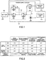
- FIG. 2 is a diagram for explaining on/off switching of each switch.
- SW1 and SW3 are turned on to electrically connect the battery 200 with the capacitor 110.
- SW2 is turned off in the initial state.
- the switch SW4 is turned off so as not to supply power from the capacitor 110 to the backup load 210.
- FIG. 3 shows the current path (thick line) at this time.
- the backup load 210 is supplied with power from the battery 200.
- the capacitor 110 is charged by the path from the battery 200, via SW1, to SW3. Since the resistor R1 is connected to SW1, excessive inrush current to the capacitor 110 can be prevented.
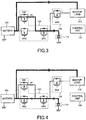
- SW2 is switched on after a lapse of a predetermined time since SW1 and SW3 are switched on.
- FIG. 4 shows the current path at this time. Since the main path for charging the capacitor 110 is switched from SW1 to SW2, power consumption at the resistor R1 can be suppressed.
- the first switch 130 for switching the connection state between the battery 200 and the capacitor 110 is turned on, and the second switch 140 for switching the connection state between the capacitor 110 and the backup with the load 210 is turned off.
- the control unit 120 monitors the charging voltage of the capacitor 110, and when detecting that the charging is completed, switches the SW1 off.
- FIG. 4 shows the current path at this time. As shown in this figure, the current path from the capacitor 110 to the battery 200 via SW3, SW2 is formed. Incidentally, when the parasitic diode of SW3 is used, SW3 may be turned off.
- the capacitor 110 which has been charged with this current path, can supply power to the backup load 210 and general loads (not shown) together with the battery 200. That is, the capacitor 110 also plays a role of supporting the battery 200. Thus, the capacitor 110 can be effectively used.
- the capacitor 110 releases electric charge, thereby preventing an excessive burden from being applied to the battery 200.
- the charge that can be supplied to the backup load 210 is reserved.
- the first switch 130 for switching the connection state between the battery 200 and the capacitor 110 is turned on, and the second switch 140 for switching the connection state between the capacitor 110 and the backup load 210 is turned off. That is, in the present embodiment, the connection between the battery 200 and the capacitor 110 is maintained even after the capacitor 110 is charged.
- FIG. 6 shows the current path at this time.
- the capacitor 110 supplies power to the backup load 210 instead of the battery 200 in which the abnormality has occurred.
- the first switch 130 for switching the connection state between the battery 200 and the capacitor 110 is turned off, and the second switch 140 for switching the connection state between the capacitor 110 and the backup load 210 is turned on.
- SW1, SW2, and SW4 may be turned off and only SW3 may be turned on.
- the coasting is a traveling operation in which the engine and the tire are disconnected from each other and the vehicle skids due to the inertia of the vehicle.
- the control unit 120 determines that priority is given to power supply to the backup load 210 when the vehicle enters a predetermined state such as coasting.
- FIG. 7 shows the current path at this time.
- the backup load 210 can receive power supply preferentially from the battery 200. Since SW3 is turned on, the capacitor 110 can be charged using the parasitic diode of SW2.
- the first switch 130 for switching the connection state between the battery 200 and the capacitor 110 is turned off, and the second switch 140 for switching the connection state between the capacitor 110 and the backup load 210 is turned off.
- a current path from the battery 200 to the capacitor 110 is formed by the parasitic diode of the first switch 130.
- the capacitor 110 can support the battery 200 so that the capacitor 110 is effectively used.
Landscapes
- Engineering & Computer Science (AREA)
- Power Engineering (AREA)
- Business, Economics & Management (AREA)
- Emergency Management (AREA)
- Transportation (AREA)
- Mechanical Engineering (AREA)
- Charge And Discharge Circuits For Batteries Or The Like (AREA)
- Stand-By Power Supply Arrangements (AREA)
Abstract
Description
- The present invention relates to a power supply device for supplying power to a load when a battery abnormality occurs.
- A vehicle such as an automobile includes a battery for supplying power to a load of an electronic control device, an electric device, or the like. As a battery, a 12 V lead storage battery is widely used. The loads to which electric power are supplied from the battery relate to functions such as running, steering, stopping, opening and closing of the door, etc., and includes a load (hereinafter referred to as a "backup load") that the power supply is preferably maintained even when the battery fails.
- In the
Patent Literature 1, as shown inFIG. 8 , it is described that acapacitor 330 is previously charged by using a step-downcircuit 320 connected to abattery 310 and when acontrol unit 360 detects abnormality of thebattery 310, it controls aboost circuit 340 to boost the charge voltage of thecapacitor 330 and supplies to abackup load 350. - Patent Literature 1:
JP 5618024 B - In the invention described in
Patent Literature 1, thecapacitor 330 is used only for the purpose of operating thebackup load 350 when thebattery 310 fails, and it cannot be said that thecapacitor 330 is fully utilized effectively. - Accordingly, it is an object of the present invention to effectively utilize a capacitor for supplying power to a load when a battery abnormality occurs.
- In order to solve the above problem, according to a first aspect of the present invention, there is provided a power supply device for connecting to a battery and a load to which power is supplied from the battery including:
- a capacitor;
- a first switch for switching a connection state between the battery and the capacitor;
- a second switch for switching a connection state between the capacitor and the load; and
- a control unit for detecting a state of charge of the capacitor and abnormality of the battery,
- wherein when not detecting abnormality of the battery, the control unit turns on the first switch and turns off the second switch when the capacitor is not fully charged, and maintains the first switch on after the capacitor is fully charged.
- Here, when detecting the abnormality of the battery, the control unit turns off the first switch and turns on the second switch.
- Further, when a predetermined condition is satisfied, the control unit determines that priority is given to power supply to the load, and turns off the first switch and turns off the second switch.
- Further, the first switch includes:
- a second semiconductor switch and a third semiconductor switch connected in series between the battery and the capacitor; and
- a first semiconductor switch connected in parallel with the second semiconductor switch and connected in series with a resistor.
- At this time, in the first semiconductor switch and the second semiconductor switch, an anode of a parasitic diode is disposed on a side of the battery, and in the third semiconductor switch, the anode of the parasitic diode is arranged on a side of the capacitor.
- According to the present invention, it is possible to effectively utilize the capacitor for supplying the power to the load when the battery abnormality occurs.
-
-
FIG. 1 is a block diagram showing a configuration of a power supply device according to the present embodiment; -
FIG. 2 is a diagram for explaining switches switching; -
FIG. 3 is a diagram for explaining a power supply path at the time of charging a capacitor immediately after start-up; -
FIG. 4 is a diagram for explaining a power supply path during capacitor charging; -
FIG. 5 is a diagram for explaining a power supply path during battery support; -
FIG. 6 is a diagram for explaining a power supply path at a time of a battery abnormality; -
FIG. 7 is a diagram for explaining a power supply path at the time of giving priority to backup load power supply; and -
FIG. 8 is a diagram for explaining a capacitor that supplies power to a load when a power failure occurs. - Embodiments of the present invention will be described in detail with reference to the drawings.
FIG. 1 is a block diagram showing a configuration of apower supply device 100 according to the present embodiment. In this figure, power is supplied to abackup load 210 from abattery 200. - The
power supply device 100 is installed in a vehicle, for example, and is a device that supplies power to thebackup load 210 when thebattery 200 fails. Here, thebackup load 210 is related to functions such as running, steering, stopping, door opening and closing, etc. and preferably the power supply is maintained even when thebattery 200 is abnormal. Although not shown, general loads other than thebackup load 210 are also connected to thebattery 200. In addition, ISG (generator with motor function) etc. may be connected. - As shown in this figure, the
power supply device 100 includes SW1, SW2, SW3, and SW4, each of which is constituted by a semiconductor switch, a resistor R1, acapacitor 110, and acontrol unit 120. Thecapacitor 110 can be, for example, an electric double layer capacitor (EDLC) having a long lifetime and high capacity. In addition, a DCDC converter may be arranged in front of thecapacitor 110. - SW2, SW3, and the
capacitor 110 are connected in series to thebattery 200. In addition, in parallel with SW2, a series circuit of SW1 and resistor R1 is connected. Further, thecapacitor 110 is connected to thebackup load 210 via SW4. - In SW1 and SW2, the anode of the parasitic diode is disposed on the side of the
battery 200, and the anode of the parasitic diode of SW3 is disposed on the side of thecapacitor 110. That is, the cathodes of the SW2 and SW3 are connected to each other. Further, in SW4, the anode of the parasitic diode is arranged on the side of thebackup load 210. - SW1, SW2 and SW3 function as a
first switch 130 for switching the connection state between thebattery 200 and thecapacitor 110. SW4 functions as asecond switch 140 for switching the connection state between thecapacitor 110 and thebackup load 210. - The
control unit 120 monitors the state of the vehicle, the state of thebattery 200, the charged state of thecapacitor 110, and the like, and controls ON/OFF of SW1, SW2, SW3, and SW4. Incidentally, a control function may be provided for the SW4 that switches the connection state between thecapacitor 110 and thebackup load 210. In this case, when the SW4 detects abnormality of thebattery 200, accident of the vehicle, etc., it controls so that thecapacitor 110 and thebackup load 210 are connected. - Next, the operation of the
power supply device 100 having the above configuration will be described.FIG. 2 is a diagram for explaining on/off switching of each switch. When thecapacitor 110 is charged, for example, when the vehicle is started, SW1 and SW3 are turned on to electrically connect thebattery 200 with thecapacitor 110. SW2 is turned off in the initial state. Further, the switch SW4 is turned off so as not to supply power from thecapacitor 110 to thebackup load 210. -
FIG. 3 shows the current path (thick line) at this time. Thebackup load 210 is supplied with power from thebattery 200. Thecapacitor 110 is charged by the path from thebattery 200, via SW1, to SW3. Since the resistor R1 is connected to SW1, excessive inrush current to thecapacitor 110 can be prevented. - SW2 is switched on after a lapse of a predetermined time since SW1 and SW3 are switched on.
FIG. 4 shows the current path at this time. Since the main path for charging thecapacitor 110 is switched from SW1 to SW2, power consumption at the resistor R1 can be suppressed. - Focusing on the connection relationships between the
battery 200 and thecapacitor 110 and between thecapacitor 110 and thebackup load 210 at the time of charging thecapacitor 110, thefirst switch 130 for switching the connection state between thebattery 200 and thecapacitor 110 is turned on, and thesecond switch 140 for switching the connection state between thecapacitor 110 and the backup with theload 210 is turned off. - During normal traveling or the like, the
control unit 120 monitors the charging voltage of thecapacitor 110, and when detecting that the charging is completed, switches the SW1 off.FIG. 4 shows the current path at this time. As shown in this figure, the current path from thecapacitor 110 to thebattery 200 via SW3, SW2 is formed. Incidentally, when the parasitic diode of SW3 is used, SW3 may be turned off. - The
capacitor 110, which has been charged with this current path, can supply power to thebackup load 210 and general loads (not shown) together with thebattery 200. That is, thecapacitor 110 also plays a role of supporting thebattery 200. Thus, thecapacitor 110 can be effectively used. - For example, in the case where a large current is instantaneously required for the load, the
capacitor 110 releases electric charge, thereby preventing an excessive burden from being applied to thebattery 200. However, it is assumed that the charge that can be supplied to thebackup load 210 is reserved. - Focusing on the connection relationships between the
battery 200 and thecapacitor 110 and between thecapacitor 110 and thebackup load 210 after the charging of thecapacitor 110, thefirst switch 130 for switching the connection state between thebattery 200 and thecapacitor 110 is turned on, and thesecond switch 140 for switching the connection state between thecapacitor 110 and thebackup load 210 is turned off. That is, in the present embodiment, the connection between thebattery 200 and thecapacitor 110 is maintained even after thecapacitor 110 is charged. - When an abnormality occurs in the
battery 200 due to a battery failure or the like during traveling, the switches SW1, SW2, and SW3 are turned off to disconnect the path between thebattery 200 and thecapacitor 110, and the switch SW4 is turned on.FIG. 6 shows the current path at this time. Thecapacitor 110 supplies power to thebackup load 210 instead of thebattery 200 in which the abnormality has occurred. - Focusing on the connection relationships between the
battery 200 and thecapacitor 110 and between thecapacitor 110 and thebackup load 210 at the time of abnormality of thebattery 200, thefirst switch 130 for switching the connection state between thebattery 200 and thecapacitor 110 is turned off, and thesecond switch 140 for switching the connection state between thecapacitor 110 and thebackup load 210 is turned on. - In the case of giving priority to power supply to the
backup load 210 at the time of performing coasting or the like after charging, SW1, SW2, and SW4 may be turned off and only SW3 may be turned on. Here, the coasting is a traveling operation in which the engine and the tire are disconnected from each other and the vehicle skids due to the inertia of the vehicle. Thecontrol unit 120 determines that priority is given to power supply to thebackup load 210 when the vehicle enters a predetermined state such as coasting.FIG. 7 shows the current path at this time. - Due to this current path, the
backup load 210 can receive power supply preferentially from thebattery 200. Since SW3 is turned on, thecapacitor 110 can be charged using the parasitic diode of SW2. - Focusing on the connection relationships between the
battery 200 and thecapacitor 110 and between thecapacitor 110 and thebackup load 210 in the case of giving priority to power supply to thebackup load 210 after charging thecapacitor 110, thefirst switch 130 for switching the connection state between thebattery 200 and thecapacitor 110 is turned off, and thesecond switch 140 for switching the connection state between thecapacitor 110 and thebackup load 210 is turned off. However, a current path from thebattery 200 to thecapacitor 110 is formed by the parasitic diode of thefirst switch 130. - As described above, according to the
power supply device 100 of the present embodiment, since thefirst switch 130, which switches the connection state between thecapacitor 110 that supplies power to thebackup load 210 when thebattery 200 is in an abnormal state and thebattery 200, maintains on even after charging of thecapacitor 110, thecapacitor 110 can support thebattery 200 so that thecapacitor 110 is effectively used. -
- 100
- Power supply device
- 110
- Capacitor
- 120
- Control unit
- 130
- First switch
- 140
- Second switch
- 200
- Battery
- 210
- Backup load
Claims (5)
- A power supply device for connecting to a battery and a load to which power is supplied from the battery comprising:a capacitor;a first switch for switching a connection state between the battery and the capacitor;a second switch for switching a connection state between the capacitor and the load; anda control unit for detecting a state of charge of the capacitor and abnormality of the battery,wherein when not detecting abnormality of the battery, the control unit turns on the first switch and turns off the second switch when the capacitor is not fully charged, and maintains the first switch on after the capacitor is fully charged.
- The power supply device as claimed in claim 1,
wherein when detecting the abnormality of the battery, the control unit turns off the first switch and turns on the second switch. - The power supply device as claimed in claim 1 or 2,
wherein when a predetermined condition is satisfied, the control unit determines that priority is given to power supply to the load, and turns off the first switch and turns off the second switch. - The power supply device as claimed in any one of claims 1 to 3,
wherein the first switch includes:a second semiconductor switch and a third semiconductor switch connected in series between the battery and the capacitor; anda first semiconductor switch connected in parallel with the second semiconductor switch and connected in series with a resistor. - The power supply device as claimed in claim 4,
wherein in the first semiconductor switch and the second semiconductor switch, an anode of a parasitic diode is disposed on a side of the battery, and in the third semiconductor switch, the anode of the parasitic diode is arranged on a side of the capacitor.
Applications Claiming Priority (1)
| Application Number | Priority Date | Filing Date | Title |
|---|---|---|---|
| JP2018075176A JP6732831B2 (en) | 2018-04-10 | 2018-04-10 | Power supply |
Publications (2)
| Publication Number | Publication Date |
|---|---|
| EP3553907A1 true EP3553907A1 (en) | 2019-10-16 |
| EP3553907B1 EP3553907B1 (en) | 2023-07-19 |
Family
ID=65904301
Family Applications (1)
| Application Number | Title | Priority Date | Filing Date |
|---|---|---|---|
| EP19164555.5A Active EP3553907B1 (en) | 2018-04-10 | 2019-03-22 | Power supply device |
Country Status (4)
| Country | Link |
|---|---|
| US (1) | US10868439B2 (en) |
| EP (1) | EP3553907B1 (en) |
| JP (1) | JP6732831B2 (en) |
| CN (1) | CN110365098B (en) |
Families Citing this family (6)
| Publication number | Priority date | Publication date | Assignee | Title |
|---|---|---|---|---|
| JP7254270B2 (en) * | 2019-06-03 | 2023-04-10 | マツダ株式会社 | vehicle drive |
| JP2022047802A (en) * | 2020-09-14 | 2022-03-25 | キヤノン株式会社 | Electronic apparatus, battery pack, control method and program |
| CN113346588A (en) * | 2021-06-10 | 2021-09-03 | 上海睿尤准智控技术有限公司 | Drive power supply framework for enhancing drive transient power |
| JP2023011407A (en) * | 2021-07-12 | 2023-01-24 | 矢崎総業株式会社 | power supply |
| JP2023183645A (en) | 2022-06-16 | 2023-12-28 | トヨタ自動車株式会社 | Power supply equipment and vehicles |
| JP2025053921A (en) * | 2023-09-26 | 2025-04-07 | トヨタ自動車株式会社 | Redundant Power System |
Citations (5)
| Publication number | Priority date | Publication date | Assignee | Title |
|---|---|---|---|---|
| JPS5618024B2 (en) | 1973-07-28 | 1981-04-25 | ||
| US20050269870A1 (en) * | 2003-07-08 | 2005-12-08 | Toshihiko Ohashi | Power supply for vehicle |
| US20160248247A1 (en) * | 2015-02-20 | 2016-08-25 | Omron Automotive Electronics Co., Ltd. | Voltage conversion apparatus |
| GB2545587A (en) * | 2017-03-10 | 2017-06-21 | 02Micro Inc | Systems and methods for controlling battery current |
| WO2017141686A1 (en) * | 2016-02-17 | 2017-08-24 | 株式会社オートネットワーク技術研究所 | Switch device for in-vehicle power supply, and in-vehicle power supply device |
Family Cites Families (18)
| Publication number | Priority date | Publication date | Assignee | Title |
|---|---|---|---|---|
| JPH0781515A (en) * | 1993-09-14 | 1995-03-28 | Nippondenso Co Ltd | Vehicular occupant protecting device |
| JP3741630B2 (en) * | 2001-09-18 | 2006-02-01 | Necトーキン株式会社 | POWER CIRCUIT, ELECTRONIC DEVICE HAVING THE POWER CIRCUIT, AND METHOD FOR CONTROLLING POWER CIRCUIT |
| JP4001060B2 (en) * | 2003-02-18 | 2007-10-31 | 富士電機システムズ株式会社 | Power converter |
| KR100702362B1 (en) * | 2004-10-06 | 2007-04-02 | 삼성전자주식회사 | Power Supply Circuit and Method for Stable Shutdown |
| JP2010016996A (en) * | 2008-07-03 | 2010-01-21 | Sanken Electric Co Ltd | Uninterruptible power supply unit |
| JP5200986B2 (en) * | 2009-02-17 | 2013-06-05 | 新神戸電機株式会社 | Power supply |
| JP5627264B2 (en) * | 2010-03-27 | 2014-11-19 | 三洋電機株式会社 | Power supply device for vehicle and vehicle equipped with this power supply device |
| TW201206003A (en) * | 2010-07-22 | 2012-02-01 | Eneraiser Technology Co Ltd | Abnormal-voltage protection circuit of DC power supply equipments |
| CN102904329B (en) * | 2011-07-29 | 2016-04-20 | 富泰华工业(深圳)有限公司 | Electric power management circuit |
| CN103095099B (en) * | 2011-10-31 | 2016-02-03 | 英飞特电子(杭州)股份有限公司 | A kind of load driving circuits |
| US9013056B2 (en) | 2012-02-22 | 2015-04-21 | Panasonic Intellectual Property Management Co., Ltd. | Backup power source device and automobile equipped with same |
| JP2014045551A (en) * | 2012-08-24 | 2014-03-13 | Sanyo Electric Co Ltd | Battery pack and discharge control method therefor |
| CN105324274B (en) * | 2013-07-31 | 2017-08-25 | 三洋电机株式会社 | Automotive power supply system |
| JP2015209058A (en) * | 2014-04-25 | 2015-11-24 | オムロンオートモーティブエレクトロニクス株式会社 | Power supply |
| CN207283184U (en) * | 2015-04-10 | 2018-04-27 | 张磊 | Emergency starting device |
| JP6304500B2 (en) * | 2015-07-31 | 2018-04-04 | 本田技研工業株式会社 | Vehicle power supply |
| US10700527B2 (en) * | 2016-03-25 | 2020-06-30 | Sharp Kabushiki Kaisha | Power generation system, power conditioner, power control device, power control method, and power control program |
| JP6732837B2 (en) * | 2018-04-27 | 2020-07-29 | 矢崎総業株式会社 | Power redundancy system |
-
2018
- 2018-04-10 JP JP2018075176A patent/JP6732831B2/en active Active
-
2019
- 2019-03-11 US US16/298,386 patent/US10868439B2/en active Active
- 2019-03-22 EP EP19164555.5A patent/EP3553907B1/en active Active
- 2019-04-10 CN CN201910284496.2A patent/CN110365098B/en not_active Expired - Fee Related
Patent Citations (6)
| Publication number | Priority date | Publication date | Assignee | Title |
|---|---|---|---|---|
| JPS5618024B2 (en) | 1973-07-28 | 1981-04-25 | ||
| US20050269870A1 (en) * | 2003-07-08 | 2005-12-08 | Toshihiko Ohashi | Power supply for vehicle |
| US20160248247A1 (en) * | 2015-02-20 | 2016-08-25 | Omron Automotive Electronics Co., Ltd. | Voltage conversion apparatus |
| WO2017141686A1 (en) * | 2016-02-17 | 2017-08-24 | 株式会社オートネットワーク技術研究所 | Switch device for in-vehicle power supply, and in-vehicle power supply device |
| US20180354436A1 (en) * | 2016-02-17 | 2018-12-13 | Autonetworks Technologies, Ltd. | Switch device for in-vehicle power supply, and in-vehicle power supply device |
| GB2545587A (en) * | 2017-03-10 | 2017-06-21 | 02Micro Inc | Systems and methods for controlling battery current |
Also Published As
| Publication number | Publication date |
|---|---|
| US20190312456A1 (en) | 2019-10-10 |
| CN110365098B (en) | 2023-04-07 |
| EP3553907B1 (en) | 2023-07-19 |
| US10868439B2 (en) | 2020-12-15 |
| JP2019187074A (en) | 2019-10-24 |
| JP6732831B2 (en) | 2020-07-29 |
| CN110365098A (en) | 2019-10-22 |
Similar Documents
| Publication | Publication Date | Title |
|---|---|---|
| US10889201B2 (en) | Power redundancy system | |
| EP3553907B1 (en) | Power supply device | |
| US10992169B2 (en) | Vehicle-mounted backup device | |
| US9789769B2 (en) | Power supply device for vehicles | |
| US9855905B2 (en) | Vehicle power supply device | |
| US11052771B2 (en) | Vehicle-mounted power supply device | |
| JP6451708B2 (en) | In-vehicle backup device | |
| US10017138B2 (en) | Power supply management system and power supply management method | |
| CN112041200B (en) | On-vehicle backup circuit and on-vehicle backup device | |
| EP2736146A1 (en) | Vehicle power unit | |
| JP7660320B2 (en) | Backup power system and mobile | |
| CN115051423B (en) | Charge-discharge control device | |
| JP7596769B2 (en) | Power Control Unit | |
| KR20200042136A (en) | Automobile Battery Emergency Charging Device and Method | |
| JP7059982B2 (en) | In-vehicle backup power supply | |
| JP2012035756A (en) | Power supply device for vehicle | |
| CN107921917A (en) | Vehicle-mounted power supply device | |
| US10850691B2 (en) | Management device and power supply system | |
| JP7783795B2 (en) | Vehicle Power System | |
| JP7726415B2 (en) | Power supply system and program |
Legal Events
| Date | Code | Title | Description |
|---|---|---|---|
| PUAI | Public reference made under article 153(3) epc to a published international application that has entered the european phase |
Free format text: ORIGINAL CODE: 0009012 |
|
| STAA | Information on the status of an ep patent application or granted ep patent |
Free format text: STATUS: REQUEST FOR EXAMINATION WAS MADE |
|
| 17P | Request for examination filed |
Effective date: 20190322 |
|
| AK | Designated contracting states |
Kind code of ref document: A1 Designated state(s): AL AT BE BG CH CY CZ DE DK EE ES FI FR GB GR HR HU IE IS IT LI LT LU LV MC MK MT NL NO PL PT RO RS SE SI SK SM TR |
|
| AX | Request for extension of the european patent |
Extension state: BA ME |
|
| RBV | Designated contracting states (corrected) |
Designated state(s): AL AT BE BG CH CY CZ DE DK EE ES FI FR GB GR HR HU IE IS IT LI LT LU LV MC MK MT NL NO PL PT RO RS SE SI SK SM TR |
|
| STAA | Information on the status of an ep patent application or granted ep patent |
Free format text: STATUS: EXAMINATION IS IN PROGRESS |
|
| 17Q | First examination report despatched |
Effective date: 20211029 |
|
| REG | Reference to a national code |
Ref country code: DE Free format text: PREVIOUS MAIN CLASS: H02J0001100000 Ref country code: DE Ref legal event code: R079 Ref document number: 602019032857 Country of ref document: DE Free format text: PREVIOUS MAIN CLASS: H02J0001100000 Ipc: H02J0007340000 |
|
| GRAP | Despatch of communication of intention to grant a patent |
Free format text: ORIGINAL CODE: EPIDOSNIGR1 |
|
| STAA | Information on the status of an ep patent application or granted ep patent |
Free format text: STATUS: GRANT OF PATENT IS INTENDED |
|
| RIC1 | Information provided on ipc code assigned before grant |
Ipc: H02J 9/06 20060101ALN20230417BHEP Ipc: H02J 7/00 20060101ALN20230417BHEP Ipc: H02J 1/10 20060101ALN20230417BHEP Ipc: B60L 1/10 20060101ALI20230417BHEP Ipc: H02J 1/08 20060101ALI20230417BHEP Ipc: H02J 7/34 20060101AFI20230417BHEP |
|
| INTG | Intention to grant announced |
Effective date: 20230503 |
|
| RAP3 | Party data changed (applicant data changed or rights of an application transferred) |
Owner name: YAZAKI CORPORATION |
|
| GRAS | Grant fee paid |
Free format text: ORIGINAL CODE: EPIDOSNIGR3 |
|
| GRAA | (expected) grant |
Free format text: ORIGINAL CODE: 0009210 |
|
| STAA | Information on the status of an ep patent application or granted ep patent |
Free format text: STATUS: THE PATENT HAS BEEN GRANTED |
|
| AK | Designated contracting states |
Kind code of ref document: B1 Designated state(s): AL AT BE BG CH CY CZ DE DK EE ES FI FR GB GR HR HU IE IS IT LI LT LU LV MC MK MT NL NO PL PT RO RS SE SI SK SM TR |
|
| REG | Reference to a national code |
Ref country code: GB Ref legal event code: FG4D |
|
| REG | Reference to a national code |
Ref country code: CH Ref legal event code: EP |
|
| REG | Reference to a national code |
Ref country code: DE Ref legal event code: R096 Ref document number: 602019032857 Country of ref document: DE |
|
| REG | Reference to a national code |
Ref country code: IE Ref legal event code: FG4D |
|
| REG | Reference to a national code |
Ref country code: LT Ref legal event code: MG9D |
|
| REG | Reference to a national code |
Ref country code: NL Ref legal event code: MP Effective date: 20230719 |
|
| REG | Reference to a national code |
Ref country code: AT Ref legal event code: MK05 Ref document number: 1590467 Country of ref document: AT Kind code of ref document: T Effective date: 20230719 |
|
| PG25 | Lapsed in a contracting state [announced via postgrant information from national office to epo] |
Ref country code: NL Free format text: LAPSE BECAUSE OF FAILURE TO SUBMIT A TRANSLATION OF THE DESCRIPTION OR TO PAY THE FEE WITHIN THE PRESCRIBED TIME-LIMIT Effective date: 20230719 |
|
| PG25 | Lapsed in a contracting state [announced via postgrant information from national office to epo] |
Ref country code: GR Free format text: LAPSE BECAUSE OF FAILURE TO SUBMIT A TRANSLATION OF THE DESCRIPTION OR TO PAY THE FEE WITHIN THE PRESCRIBED TIME-LIMIT Effective date: 20231020 |
|
| PG25 | Lapsed in a contracting state [announced via postgrant information from national office to epo] |
Ref country code: IS Free format text: LAPSE BECAUSE OF FAILURE TO SUBMIT A TRANSLATION OF THE DESCRIPTION OR TO PAY THE FEE WITHIN THE PRESCRIBED TIME-LIMIT Effective date: 20231119 |
|
| PG25 | Lapsed in a contracting state [announced via postgrant information from national office to epo] |
Ref country code: SE Free format text: LAPSE BECAUSE OF FAILURE TO SUBMIT A TRANSLATION OF THE DESCRIPTION OR TO PAY THE FEE WITHIN THE PRESCRIBED TIME-LIMIT Effective date: 20230719 Ref country code: RS Free format text: LAPSE BECAUSE OF FAILURE TO SUBMIT A TRANSLATION OF THE DESCRIPTION OR TO PAY THE FEE WITHIN THE PRESCRIBED TIME-LIMIT Effective date: 20230719 Ref country code: PT Free format text: LAPSE BECAUSE OF FAILURE TO SUBMIT A TRANSLATION OF THE DESCRIPTION OR TO PAY THE FEE WITHIN THE PRESCRIBED TIME-LIMIT Effective date: 20231120 Ref country code: NO Free format text: LAPSE BECAUSE OF FAILURE TO SUBMIT A TRANSLATION OF THE DESCRIPTION OR TO PAY THE FEE WITHIN THE PRESCRIBED TIME-LIMIT Effective date: 20231019 Ref country code: LV Free format text: LAPSE BECAUSE OF FAILURE TO SUBMIT A TRANSLATION OF THE DESCRIPTION OR TO PAY THE FEE WITHIN THE PRESCRIBED TIME-LIMIT Effective date: 20230719 Ref country code: LT Free format text: LAPSE BECAUSE OF FAILURE TO SUBMIT A TRANSLATION OF THE DESCRIPTION OR TO PAY THE FEE WITHIN THE PRESCRIBED TIME-LIMIT Effective date: 20230719 Ref country code: IS Free format text: LAPSE BECAUSE OF FAILURE TO SUBMIT A TRANSLATION OF THE DESCRIPTION OR TO PAY THE FEE WITHIN THE PRESCRIBED TIME-LIMIT Effective date: 20231119 Ref country code: HR Free format text: LAPSE BECAUSE OF FAILURE TO SUBMIT A TRANSLATION OF THE DESCRIPTION OR TO PAY THE FEE WITHIN THE PRESCRIBED TIME-LIMIT Effective date: 20230719 Ref country code: GR Free format text: LAPSE BECAUSE OF FAILURE TO SUBMIT A TRANSLATION OF THE DESCRIPTION OR TO PAY THE FEE WITHIN THE PRESCRIBED TIME-LIMIT Effective date: 20231020 Ref country code: FI Free format text: LAPSE BECAUSE OF FAILURE TO SUBMIT A TRANSLATION OF THE DESCRIPTION OR TO PAY THE FEE WITHIN THE PRESCRIBED TIME-LIMIT Effective date: 20230719 Ref country code: AT Free format text: LAPSE BECAUSE OF FAILURE TO SUBMIT A TRANSLATION OF THE DESCRIPTION OR TO PAY THE FEE WITHIN THE PRESCRIBED TIME-LIMIT Effective date: 20230719 |
|
| PG25 | Lapsed in a contracting state [announced via postgrant information from national office to epo] |
Ref country code: PL Free format text: LAPSE BECAUSE OF FAILURE TO SUBMIT A TRANSLATION OF THE DESCRIPTION OR TO PAY THE FEE WITHIN THE PRESCRIBED TIME-LIMIT Effective date: 20230719 |
|
| REG | Reference to a national code |
Ref country code: DE Ref legal event code: R097 Ref document number: 602019032857 Country of ref document: DE |
|
| PG25 | Lapsed in a contracting state [announced via postgrant information from national office to epo] |
Ref country code: ES Free format text: LAPSE BECAUSE OF FAILURE TO SUBMIT A TRANSLATION OF THE DESCRIPTION OR TO PAY THE FEE WITHIN THE PRESCRIBED TIME-LIMIT Effective date: 20230719 |
|
| PG25 | Lapsed in a contracting state [announced via postgrant information from national office to epo] |
Ref country code: SM Free format text: LAPSE BECAUSE OF FAILURE TO SUBMIT A TRANSLATION OF THE DESCRIPTION OR TO PAY THE FEE WITHIN THE PRESCRIBED TIME-LIMIT Effective date: 20230719 Ref country code: RO Free format text: LAPSE BECAUSE OF FAILURE TO SUBMIT A TRANSLATION OF THE DESCRIPTION OR TO PAY THE FEE WITHIN THE PRESCRIBED TIME-LIMIT Effective date: 20230719 Ref country code: ES Free format text: LAPSE BECAUSE OF FAILURE TO SUBMIT A TRANSLATION OF THE DESCRIPTION OR TO PAY THE FEE WITHIN THE PRESCRIBED TIME-LIMIT Effective date: 20230719 Ref country code: EE Free format text: LAPSE BECAUSE OF FAILURE TO SUBMIT A TRANSLATION OF THE DESCRIPTION OR TO PAY THE FEE WITHIN THE PRESCRIBED TIME-LIMIT Effective date: 20230719 Ref country code: DK Free format text: LAPSE BECAUSE OF FAILURE TO SUBMIT A TRANSLATION OF THE DESCRIPTION OR TO PAY THE FEE WITHIN THE PRESCRIBED TIME-LIMIT Effective date: 20230719 Ref country code: CZ Free format text: LAPSE BECAUSE OF FAILURE TO SUBMIT A TRANSLATION OF THE DESCRIPTION OR TO PAY THE FEE WITHIN THE PRESCRIBED TIME-LIMIT Effective date: 20230719 Ref country code: SK Free format text: LAPSE BECAUSE OF FAILURE TO SUBMIT A TRANSLATION OF THE DESCRIPTION OR TO PAY THE FEE WITHIN THE PRESCRIBED TIME-LIMIT Effective date: 20230719 |
|
| PLBE | No opposition filed within time limit |
Free format text: ORIGINAL CODE: 0009261 |
|
| STAA | Information on the status of an ep patent application or granted ep patent |
Free format text: STATUS: NO OPPOSITION FILED WITHIN TIME LIMIT |
|
| PG25 | Lapsed in a contracting state [announced via postgrant information from national office to epo] |
Ref country code: IT Free format text: LAPSE BECAUSE OF FAILURE TO SUBMIT A TRANSLATION OF THE DESCRIPTION OR TO PAY THE FEE WITHIN THE PRESCRIBED TIME-LIMIT Effective date: 20230719 |
|
| 26N | No opposition filed |
Effective date: 20240422 |
|
| PG25 | Lapsed in a contracting state [announced via postgrant information from national office to epo] |
Ref country code: SI Free format text: LAPSE BECAUSE OF FAILURE TO SUBMIT A TRANSLATION OF THE DESCRIPTION OR TO PAY THE FEE WITHIN THE PRESCRIBED TIME-LIMIT Effective date: 20230719 |
|
| REG | Reference to a national code |
Ref country code: CH Ref legal event code: PL |
|
| PG25 | Lapsed in a contracting state [announced via postgrant information from national office to epo] |
Ref country code: BG Free format text: LAPSE BECAUSE OF FAILURE TO SUBMIT A TRANSLATION OF THE DESCRIPTION OR TO PAY THE FEE WITHIN THE PRESCRIBED TIME-LIMIT Effective date: 20230719 |
|
| PG25 | Lapsed in a contracting state [announced via postgrant information from national office to epo] |
Ref country code: LU Free format text: LAPSE BECAUSE OF NON-PAYMENT OF DUE FEES Effective date: 20240322 |
|
| PG25 | Lapsed in a contracting state [announced via postgrant information from national office to epo] |
Ref country code: MC Free format text: LAPSE BECAUSE OF FAILURE TO SUBMIT A TRANSLATION OF THE DESCRIPTION OR TO PAY THE FEE WITHIN THE PRESCRIBED TIME-LIMIT Effective date: 20230719 |
|
| GBPC | Gb: european patent ceased through non-payment of renewal fee |
Effective date: 20240322 |
|
| PG25 | Lapsed in a contracting state [announced via postgrant information from national office to epo] |
Ref country code: MC Free format text: LAPSE BECAUSE OF FAILURE TO SUBMIT A TRANSLATION OF THE DESCRIPTION OR TO PAY THE FEE WITHIN THE PRESCRIBED TIME-LIMIT Effective date: 20230719 Ref country code: LU Free format text: LAPSE BECAUSE OF NON-PAYMENT OF DUE FEES Effective date: 20240322 Ref country code: BG Free format text: LAPSE BECAUSE OF FAILURE TO SUBMIT A TRANSLATION OF THE DESCRIPTION OR TO PAY THE FEE WITHIN THE PRESCRIBED TIME-LIMIT Effective date: 20230719 |
|
| REG | Reference to a national code |
Ref country code: BE Ref legal event code: MM Effective date: 20240331 |
|
| PG25 | Lapsed in a contracting state [announced via postgrant information from national office to epo] |
Ref country code: BE Free format text: LAPSE BECAUSE OF NON-PAYMENT OF DUE FEES Effective date: 20240331 |
|
| PG25 | Lapsed in a contracting state [announced via postgrant information from national office to epo] |
Ref country code: GB Free format text: LAPSE BECAUSE OF NON-PAYMENT OF DUE FEES Effective date: 20240322 |
|
| PG25 | Lapsed in a contracting state [announced via postgrant information from national office to epo] |
Ref country code: FR Free format text: LAPSE BECAUSE OF NON-PAYMENT OF DUE FEES Effective date: 20240331 |
|
| PG25 | Lapsed in a contracting state [announced via postgrant information from national office to epo] |
Ref country code: IE Free format text: LAPSE BECAUSE OF NON-PAYMENT OF DUE FEES Effective date: 20240322 |
|
| PG25 | Lapsed in a contracting state [announced via postgrant information from national office to epo] |
Ref country code: IE Free format text: LAPSE BECAUSE OF NON-PAYMENT OF DUE FEES Effective date: 20240322 Ref country code: GB Free format text: LAPSE BECAUSE OF NON-PAYMENT OF DUE FEES Effective date: 20240322 Ref country code: FR Free format text: LAPSE BECAUSE OF NON-PAYMENT OF DUE FEES Effective date: 20240331 Ref country code: BE Free format text: LAPSE BECAUSE OF NON-PAYMENT OF DUE FEES Effective date: 20240331 Ref country code: CH Free format text: LAPSE BECAUSE OF NON-PAYMENT OF DUE FEES Effective date: 20240331 |
|
| PG25 | Lapsed in a contracting state [announced via postgrant information from national office to epo] |
Ref country code: CY Free format text: LAPSE BECAUSE OF FAILURE TO SUBMIT A TRANSLATION OF THE DESCRIPTION OR TO PAY THE FEE WITHIN THE PRESCRIBED TIME-LIMIT; INVALID AB INITIO Effective date: 20190322 |
|
| PG25 | Lapsed in a contracting state [announced via postgrant information from national office to epo] |
Ref country code: HU Free format text: LAPSE BECAUSE OF FAILURE TO SUBMIT A TRANSLATION OF THE DESCRIPTION OR TO PAY THE FEE WITHIN THE PRESCRIBED TIME-LIMIT; INVALID AB INITIO Effective date: 20190322 |
|
| PG25 | Lapsed in a contracting state [announced via postgrant information from national office to epo] |
Ref country code: TR Free format text: LAPSE BECAUSE OF FAILURE TO SUBMIT A TRANSLATION OF THE DESCRIPTION OR TO PAY THE FEE WITHIN THE PRESCRIBED TIME-LIMIT Effective date: 20230719 |
|
| PGFP | Annual fee paid to national office [announced via postgrant information from national office to epo] |
Ref country code: DE Payment date: 20260128 Year of fee payment: 8 |