EP3553848B1 - Improved container for lithium battery - Google Patents
Improved container for lithium battery Download PDFInfo
- Publication number
- EP3553848B1 EP3553848B1 EP19167816.8A EP19167816A EP3553848B1 EP 3553848 B1 EP3553848 B1 EP 3553848B1 EP 19167816 A EP19167816 A EP 19167816A EP 3553848 B1 EP3553848 B1 EP 3553848B1
- Authority
- EP
- European Patent Office
- Prior art keywords
- battery
- smoke detector
- discharge holes
- battery housing
- container
- Prior art date
- Legal status (The legal status is an assumption and is not a legal conclusion. Google has not performed a legal analysis and makes no representation as to the accuracy of the status listed.)
- Active
Links
Images


Classifications
-
- G—PHYSICS
- G08—SIGNALLING
- G08B—SIGNALLING OR CALLING SYSTEMS; ORDER TELEGRAPHS; ALARM SYSTEMS
- G08B17/00—Fire alarms; Alarms responsive to explosion
- G08B17/10—Actuation by presence of smoke or gases, e.g. automatic alarm devices for analysing flowing fluid materials by the use of optical means
-
- H—ELECTRICITY
- H01—ELECTRIC ELEMENTS
- H01M—PROCESSES OR MEANS, e.g. BATTERIES, FOR THE DIRECT CONVERSION OF CHEMICAL ENERGY INTO ELECTRICAL ENERGY
- H01M50/00—Constructional details or processes of manufacture of the non-active parts of electrochemical cells other than fuel cells, e.g. hybrid cells
- H01M50/20—Mountings; Secondary casings or frames; Racks, modules or packs; Suspension devices; Shock absorbers; Transport or carrying devices; Holders
- H01M50/204—Racks, modules or packs for multiple batteries or multiple cells
- H01M50/207—Racks, modules or packs for multiple batteries or multiple cells characterised by their shape
- H01M50/213—Racks, modules or packs for multiple batteries or multiple cells characterised by their shape adapted for cells having curved cross-section, e.g. round or elliptic
-
- H—ELECTRICITY
- H01—ELECTRIC ELEMENTS
- H01M—PROCESSES OR MEANS, e.g. BATTERIES, FOR THE DIRECT CONVERSION OF CHEMICAL ENERGY INTO ELECTRICAL ENERGY
- H01M50/00—Constructional details or processes of manufacture of the non-active parts of electrochemical cells other than fuel cells, e.g. hybrid cells
- H01M50/20—Mountings; Secondary casings or frames; Racks, modules or packs; Suspension devices; Shock absorbers; Transport or carrying devices; Holders
- H01M50/233—Mountings; Secondary casings or frames; Racks, modules or packs; Suspension devices; Shock absorbers; Transport or carrying devices; Holders characterised by physical properties of casings or racks, e.g. dimensions
- H01M50/24—Mountings; Secondary casings or frames; Racks, modules or packs; Suspension devices; Shock absorbers; Transport or carrying devices; Holders characterised by physical properties of casings or racks, e.g. dimensions adapted for protecting batteries from their environment, e.g. from corrosion
-
- H—ELECTRICITY
- H01—ELECTRIC ELEMENTS
- H01M—PROCESSES OR MEANS, e.g. BATTERIES, FOR THE DIRECT CONVERSION OF CHEMICAL ENERGY INTO ELECTRICAL ENERGY
- H01M50/00—Constructional details or processes of manufacture of the non-active parts of electrochemical cells other than fuel cells, e.g. hybrid cells
- H01M50/30—Arrangements for facilitating escape of gases
- H01M50/342—Non-re-sealable arrangements
-
- H—ELECTRICITY
- H01—ELECTRIC ELEMENTS
- H01M—PROCESSES OR MEANS, e.g. BATTERIES, FOR THE DIRECT CONVERSION OF CHEMICAL ENERGY INTO ELECTRICAL ENERGY
- H01M50/00—Constructional details or processes of manufacture of the non-active parts of electrochemical cells other than fuel cells, e.g. hybrid cells
- H01M50/30—Arrangements for facilitating escape of gases
- H01M50/394—Gas-pervious parts or elements
-
- H—ELECTRICITY
- H01—ELECTRIC ELEMENTS
- H01M—PROCESSES OR MEANS, e.g. BATTERIES, FOR THE DIRECT CONVERSION OF CHEMICAL ENERGY INTO ELECTRICAL ENERGY
- H01M2220/00—Batteries for particular applications
- H01M2220/10—Batteries in stationary systems, e.g. emergency power source in plant
-
- Y—GENERAL TAGGING OF NEW TECHNOLOGICAL DEVELOPMENTS; GENERAL TAGGING OF CROSS-SECTIONAL TECHNOLOGIES SPANNING OVER SEVERAL SECTIONS OF THE IPC; TECHNICAL SUBJECTS COVERED BY FORMER USPC CROSS-REFERENCE ART COLLECTIONS [XRACs] AND DIGESTS
- Y02—TECHNOLOGIES OR APPLICATIONS FOR MITIGATION OR ADAPTATION AGAINST CLIMATE CHANGE
- Y02E—REDUCTION OF GREENHOUSE GAS [GHG] EMISSIONS, RELATED TO ENERGY GENERATION, TRANSMISSION OR DISTRIBUTION
- Y02E60/00—Enabling technologies; Technologies with a potential or indirect contribution to GHG emissions mitigation
- Y02E60/10—Energy storage using batteries
Definitions
- US 2015/221914 on which the preamble of claim 1 is based, discloses a battery housing having a body and a lid that rotates with the body.
- US 2008/220321 discloses a plurality of battery cells, each provided with a gas discharge valve.
- US 2016/263410 discloses a fire suppression system for a fire zone.
- the present invention provides a battery container as claimed in claim 1.
- Apparatus, systems, and associated methods relate to preventing fire, explosion, and/or damage caused by battery thermal runaway.
- aircraft devices rely on battery power.
- aircraft devices and surrounding structures can be subject to damage caused by battery thermal runaway.
- the smoke detectors include non-flammable sealed battery containers with discharge holes to allow the discharge of expanding gases. During thermal runaway electrolyte is discharged harmlessly through the discharge holes, thereby preventing explosions and fire.
- FIG. 1 is a cross-sectional view of aircraft fuselage 10 including fuselage frame 12, cabin floor 14, cargo floor 16, aircraft cargo container 18, and smoke detector 20.
- Aircraft cargo container 18 is designed to store cargo in a shape that fits the cargo area of aircraft between cabin floor 14, cargo floor 16, and fuselage frame 12. This shape prevents aircraft cargo container 18 and cargo it may contain from shifting within aircraft, causing weight shifts that affect aircraft flight.
- Smoke detector 20 is mechanically coupled to the inside of aircraft cargo container 18 to detect smoke from potential fires within aircraft cargo container 18.
- FIG. 2 is a partially exploded perspective view of a smoke detector 20 including smoke detector case 22, baseplate 24, fasteners 26, press-to-test button 28, battery housing 30, battery 32, end cap 34, and discharge holes 36.
- Smoke detector case 22 is mechanically coupled to baseplate 24 by fasteners 26.
- Baseplate 24 can be mechanically coupled to the interior of an aircraft cargo container such as aircraft cargo container 18 of FIG. 1 .
- Smoke detector case 22 protects internal circuitry from being damaged by external sources such as cargo of an aircraft cargo container.
- Push-to-test button 28 allows a user to test the operability of the smoke detector by pressing push-to-test button 28.
- Battery housing 30 is made of lightweight non-flammable material. In one example, battery housing 30 and end cap 34 are made of steel. End cap 34 seals battery 32 in battery housing 30. End cap 34 threads into the opening of battery housing 30. Battery housing 30 provides protection for battery 32 from sources of mechanical damage. Battery housing 30 also provides protection to smoke detector 20 and cargo from battery 32 in case of thermal runaway.
- battery housing 30 is at least partially formed of conductive material to provide positive and negative electrical connections to battery 32.
- battery housing 30 is mechanically coupled to baseplate 24.
- battery housing 30 is monolithically formed with baseplate 24.
- Battery 32 is a lithium battery. Lithium batteries provide the benefit of a higher specific power density than sodium-ion, silver-zinc, nickel-cadmium, or other battery types. When lithium batteries are compromised by mechanical damage, internal shorting, and/or external shorting, thermal runaway can occur. Thermal runaway is an exothermic chemical reaction with a positive feedback loop. The exothermic reaction releases heat, which acts as a catalyst speeding up the chemical reaction, which in turn releases more heat, causing an exponential temperature increase. Thermal runaway can result in electrolyte breakdown, fire, and/or explosions. To prevent electrolyte breakdown, fire, and/or explosions, battery housing 30 is made of non-flammable material and end cap 34 includes discharge holes 36.
- Discharge holes 36 vent electrolyte of battery 32 during thermal runaway. Discharge holes allow expanding electrolyte to escape from battery housing 30 without causing an explosion Discharge holes 36 are formed on flat perimeter surfaces of end cap 34.
- discharge holes 36 are arranged in diametrically opposed pairs so that the force experienced by end cap 34 from electrolyte escaping from holes 36 is effectively zero. This prevents end cap 34 from accelerating and becoming a dangerous projectile. With only a single discharge hole, or an arrangement of holes that provide a force on end cap 34, end cap 34 could accelerate and may break the battery container.
- the end cap 34 can have n discharge holes spaced 360/n degrees apart. Arranged in this manner, discharge holes 36 will effectively exert zero force on end cap 34.
- discharge holes 36 are composed of one or more diametrically opposed pairs of discharge holes.
- discharge holes 36 are discharge valves that allow fluid flow in one direction.
- FIG. 3 is a perspective view of a smoke detector 20 including smoke detector case 22, baseplate 24, fasteners 26, press-to-test button 28, battery housing 30, end cap 34, discharge holes 36, battery leads 38, circuit board 40, and status light emitting diode (LED) 42.
- smoke detector case 22 is illustrated transparently to show battery leads 38, circuit board 40, and status light emitting diode (LED) 42.
- Circuit board 40 contains the components necessary for smoke detector 20 to function as a smoke detector.
- Status LED 42 is electrically coupled to circuit board 40. Status LED 42 receives power from circuit board 40.
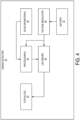
- FIG. 4 is a block diagram of smoke detector 20 including battery 32, status LED 42, processor(s) 44, accelerometer(s) 46, LED driver 48, and voltage regulator 50.
- FIG.4 is discussed with respect to smoke detector 20 of FIGs. 2 and 3 .
- Battery 32 is electrically coupled to voltage regulator 50 via battery leads 38 and circuit board 40.
- Voltage regulator 50 regulates the voltage of the power provided by battery 32 to appropriate voltages for processor(s) 44 and LED driver 48.
- Processor(s) 44 can be a microprocessor, microcontroller, or other processors.
- Accelerometer(s) 46 sense movement and/or vibration of smoke detector 20. Accelerometer(s) 46 sense movement and/or vibration when on a moving aircraft or a moving aircraft cargo container. Accelerometer(s) 46 provides a sensor signal to processor(s) 44 representative of the sensed movement and/or vibration.
- Processor(s) 44 sets a blinking rate of status LED 42 based upon the sensor signal.
- Processor(s) 44 determines if the sensed movement exceeds a threshold based upon the sensor signal. Processor(s) 44 sets the blinking rate of status LED 42 to a first blinking rate if the sensed movement/vibration is equal to or less than the threshold. Processor(s) 44 sets the blinking rate of status LED 42 to a second blinking rate if the movement/vibration exceeds the threshold. The first blinking rate is faster than the second blinking rate.
- Press-to-test button 28 is configured to set the blinking rate of status LED 42 to the first blinking rate even when the sensed movement exceeds a threshold. In one example, press-to-test button 28 is configured to set the blinking rate of status LED 42 to a third blinking rate.
- the third blinking rate can be faster than the first blinking rate.
- Processor(s) 44 provides control signals to LED driver 48.
- LED driver 48 provides power to status LED 42 based upon the blinking rate.
- the first blinking rate is once every five seconds and the second blinking rate is once every twenty seconds.
- battery containers of aircraft smoke detectors can prevent fires, explosions, and other damage using non-flammable materials and discharge holes.
- Using battery containers as described herein provides the ability to discharge battery electrolyte harmlessly during thermal runaway. This eliminates the risk of fire and prevents explosions caused by thermal runaway because a main source of heat and explosion, battery electrolyte, is discharged from the battery case.
Landscapes
- Chemical & Material Sciences (AREA)
- Chemical Kinetics & Catalysis (AREA)
- Electrochemistry (AREA)
- General Chemical & Material Sciences (AREA)
- Analytical Chemistry (AREA)
- Business, Economics & Management (AREA)
- Emergency Management (AREA)
- Physics & Mathematics (AREA)
- General Physics & Mathematics (AREA)
- Battery Mounting, Suspending (AREA)
Description
- In certain aircraft applications aircraft electrical power is not readily available, and sensing equipment relies on internal battery power. One example of this is a stand-alone smoke detector situated in an aircraft cargo container. Lithium and other battery technologies have particularly good specific power density, enabling them to provide power for months to years. However, the specific power density of lithium batteries can cause the battery to enter thermal runaway if compromised by mechanical damage and/or internal or external short circuiting. Battery thermal runaway results in damage to stand-alone smoke detectors.
-
US 2015/221914 , on which the preamble of claim 1 is based, discloses a battery housing having a body and a lid that rotates with the body.US 2008/220321 discloses a plurality of battery cells, each provided with a gas discharge valve.US 2016/263410 discloses a fire suppression system for a fire zone. - The present invention provides a battery container as claimed in claim 1.
-
-
FIG. 1 is a cross-sectional view of an aircraft fuselage. -
FIG. 2 is a partially exploded perspective view of a smoke detector. -
FIG. 3 is a partially transparent second perspective view of the smoke detector. -
FIG. 4 is a block diagram of the smoke detector. - Apparatus, systems, and associated methods relate to preventing fire, explosion, and/or damage caused by battery thermal runaway. In some applications, such as smoke detection of aircraft cargo carriers, aircraft devices rely on battery power. In these cases, aircraft devices and surrounding structures can be subject to damage caused by battery thermal runaway. Using the apparatus, systems, and associated methods herein, allows for the use of batteries with high specific power densities without risk of fire, explosion, and damage. The smoke detectors include non-flammable sealed battery containers with discharge holes to allow the discharge of expanding gases. During thermal runaway electrolyte is discharged harmlessly through the discharge holes, thereby preventing explosions and fire.
-
FIG. 1 is a cross-sectional view ofaircraft fuselage 10 includingfuselage frame 12,cabin floor 14,cargo floor 16,aircraft cargo container 18, andsmoke detector 20. -
Aircraft cargo container 18 is designed to store cargo in a shape that fits the cargo area of aircraft betweencabin floor 14,cargo floor 16, andfuselage frame 12. This shape preventsaircraft cargo container 18 and cargo it may contain from shifting within aircraft, causing weight shifts that affect aircraft flight.Smoke detector 20 is mechanically coupled to the inside ofaircraft cargo container 18 to detect smoke from potential fires withinaircraft cargo container 18. -
FIG. 2 is a partially exploded perspective view of asmoke detector 20 includingsmoke detector case 22,baseplate 24,fasteners 26, press-to-test button 28,battery housing 30,battery 32,end cap 34, anddischarge holes 36. -
Smoke detector case 22 is mechanically coupled tobaseplate 24 byfasteners 26.Baseplate 24 can be mechanically coupled to the interior of an aircraft cargo container such asaircraft cargo container 18 ofFIG. 1 .Smoke detector case 22 protects internal circuitry from being damaged by external sources such as cargo of an aircraft cargo container. Push-to-test button 28 allows a user to test the operability of the smoke detector by pressing push-to-test button 28.Battery housing 30 is made of lightweight non-flammable material. In one example,battery housing 30 andend cap 34 are made of steel. Endcap 34seals battery 32 inbattery housing 30. Endcap 34 threads into the opening ofbattery housing 30.Battery housing 30 provides protection forbattery 32 from sources of mechanical damage.Battery housing 30 also provides protection tosmoke detector 20 and cargo frombattery 32 in case of thermal runaway. In one example,battery housing 30 is at least partially formed of conductive material to provide positive and negative electrical connections tobattery 32. In one example,battery housing 30 is mechanically coupled tobaseplate 24. In a further example,battery housing 30 is monolithically formed withbaseplate 24. -
Battery 32 is a lithium battery. Lithium batteries provide the benefit of a higher specific power density than sodium-ion, silver-zinc, nickel-cadmium, or other battery types. When lithium batteries are compromised by mechanical damage, internal shorting, and/or external shorting, thermal runaway can occur. Thermal runaway is an exothermic chemical reaction with a positive feedback loop. The exothermic reaction releases heat, which acts as a catalyst speeding up the chemical reaction, which in turn releases more heat, causing an exponential temperature increase. Thermal runaway can result in electrolyte breakdown, fire, and/or explosions. To prevent electrolyte breakdown, fire, and/or explosions,battery housing 30 is made of non-flammable material andend cap 34 includesdischarge holes 36. -
Battery housing 30 andend cap 34 form a battery container. Dischargeholes 36 vent electrolyte ofbattery 32 during thermal runaway. Discharge holes allow expanding electrolyte to escape frombattery housing 30 without causing anexplosion Discharge holes 36 are formed on flat perimeter surfaces ofend cap 34. In one example,discharge holes 36 are arranged in diametrically opposed pairs so that the force experienced byend cap 34 from electrolyte escaping fromholes 36 is effectively zero. This preventsend cap 34 from accelerating and becoming a dangerous projectile. With only a single discharge hole, or an arrangement of holes that provide a force onend cap 34,end cap 34 could accelerate and may break the battery container. Theend cap 34 can have n discharge holes spaced 360/n degrees apart. Arranged in this manner,discharge holes 36 will effectively exert zero force onend cap 34. In an example,discharge holes 36 are composed of one or more diametrically opposed pairs of discharge holes. In one example,discharge holes 36 are discharge valves that allow fluid flow in one direction. -
FIG. 3 is a perspective view of asmoke detector 20 includingsmoke detector case 22,baseplate 24,fasteners 26, press-to-test button 28,battery housing 30,end cap 34,discharge holes 36, battery leads 38,circuit board 40, and status light emitting diode (LED) 42. As shown inFIG. 3 smoke detector case 22 is illustrated transparently to show battery leads 38,circuit board 40, and status light emitting diode (LED) 42. - Battery leads 38 provide power from
battery 32 tocircuit board 40.Circuit board 40 contains the components necessary forsmoke detector 20 to function as a smoke detector.Status LED 42 is electrically coupled tocircuit board 40.Status LED 42 receives power fromcircuit board 40. -
FIG. 4 is a block diagram ofsmoke detector 20 includingbattery 32,status LED 42, processor(s) 44, accelerometer(s) 46,LED driver 48, andvoltage regulator 50. For purposes of clarity and ease of discussion,FIG.4 is discussed with respect tosmoke detector 20 ofFIGs. 2 and3 . -
Battery 32 is electrically coupled tovoltage regulator 50 via battery leads 38 andcircuit board 40.Voltage regulator 50 regulates the voltage of the power provided bybattery 32 to appropriate voltages for processor(s) 44 andLED driver 48. Processor(s) 44 can be a microprocessor, microcontroller, or other processors. Accelerometer(s) 46 sense movement and/or vibration ofsmoke detector 20. Accelerometer(s) 46 sense movement and/or vibration when on a moving aircraft or a moving aircraft cargo container. Accelerometer(s) 46 provides a sensor signal to processor(s) 44 representative of the sensed movement and/or vibration. Processor(s) 44 sets a blinking rate ofstatus LED 42 based upon the sensor signal. Processor(s) 44 determines if the sensed movement exceeds a threshold based upon the sensor signal. Processor(s) 44 sets the blinking rate ofstatus LED 42 to a first blinking rate if the sensed movement/vibration is equal to or less than the threshold. Processor(s) 44 sets the blinking rate ofstatus LED 42 to a second blinking rate if the movement/vibration exceeds the threshold. The first blinking rate is faster than the second blinking rate. Press-to-test button 28 is configured to set the blinking rate ofstatus LED 42 to the first blinking rate even when the sensed movement exceeds a threshold. In one example, press-to-test button 28 is configured to set the blinking rate ofstatus LED 42 to a third blinking rate. The third blinking rate can be faster than the first blinking rate. Processor(s) 44 provides control signals toLED driver 48.LED driver 48 provides power tostatus LED 42 based upon the blinking rate. In one example the first blinking rate is once every five seconds and the second blinking rate is once every twenty seconds. - Many design/certification authorities require a continuously blinking light to provide a positive indication of smoke detector function. However, during ground transportation or flight,
smoke detector 20 is out of sight and is not subject to visual status inspections because the aircraft cargo container containingsmoke detector 20 is closed. At these times,battery 32 provides power tostatus LED 42 even thoughstatus LED 42 cannot be seen. At these times, a slower rate of blinking drains less power which extends battery life ofbattery 32. In one example, battery life ofbattery 32 is extended by 20%. - Accordingly, implementing techniques of this disclosure, battery containers of aircraft smoke detectors can prevent fires, explosions, and other damage using non-flammable materials and discharge holes. Using battery containers as described herein provides the ability to discharge battery electrolyte harmlessly during thermal runaway. This eliminates the risk of fire and prevents explosions caused by thermal runaway because a main source of heat and explosion, battery electrolyte, is discharged from the battery case.
- It is intended that the invention not be limited to the particular embodiment(s) disclosed, but that the invention will include all embodiments falling within the scope of the appended claims.
Claims (11)
- A battery container comprising:a battery housing (30) configured to house a battery (32), the battery housing (30) comprising an opening configured to receive the battery (32) into the battery housing (30); andan end cap (34) configured to seal the opening of the battery housing (30), characterised in that the end cap (34) having a circumferential perimeter comprising flat perimeter surfaces, and comprising two or more discharge holes (36) configured to release expanding gas from the battery housing (30);wherein the discharge holes (36) are formed at the flat perimeter surfaces of the end cap (34), and wherein the two or more discharge holes (36) are spaced equally along the perimeter of the end cap (34) such that the circumferential spacing between each of the two or more discharge holes (36) is equal.
- The battery container of claim 1, wherein the two or more discharge holes (36) comprise at least one pair of diametrically opposed discharge holes.
- The battery container of any preceding claim, wherein the battery housing (30) is comprised of non-flammable material.
- The battery container of any preceding claim, wherein the two or more discharge holes (36) are configured to release expanding electrolyte of the battery.
- The battery container of any preceding claim, wherein the opening of the battery housing (30) is the only opening of the battery housing (30).
- The battery container of any preceding claim, wherein the battery housing (30) is comprised of steel.
- A smoke detector (20) comprising:a battery container according to any preceding claim;a circuit board including smoke detector electronics;battery leads electrically coupled to the battery container and the circuit board; anda smoke detector case (22) to house the battery container, the circuit board, and the battery leads.
- The smoke detector of claim 7, wherein the two or more discharge holes (36) are configured to release expanding gas external to the smoke detector case (22).
- The smoke detector of claim 7 or 8, further comprising a baseplate (24) mechanically coupled to the smoke detector case (22), the baseplate (24) configured to be mechanically coupled to an aircraft cargo container (18).
- The smoke detector of claim 9, wherein the battery housing (30) is mechanically coupled to the baseplate (24).
- The smoke detector (22) of claim 9, wherein the battery housing (30) is formed monolithically to the baseplate (24).
Applications Claiming Priority (1)
| Application Number | Priority Date | Filing Date | Title |
|---|---|---|---|
| US15/949,627 US20190311594A1 (en) | 2018-04-10 | 2018-04-10 | Container for lithium battery |
Publications (2)
| Publication Number | Publication Date |
|---|---|
| EP3553848A1 EP3553848A1 (en) | 2019-10-16 |
| EP3553848B1 true EP3553848B1 (en) | 2025-01-08 |
Family
ID=66102498
Family Applications (1)
| Application Number | Title | Priority Date | Filing Date |
|---|---|---|---|
| EP19167816.8A Active EP3553848B1 (en) | 2018-04-10 | 2019-04-08 | Improved container for lithium battery |
Country Status (2)
| Country | Link |
|---|---|
| US (1) | US20190311594A1 (en) |
| EP (1) | EP3553848B1 (en) |
Families Citing this family (1)
| Publication number | Priority date | Publication date | Assignee | Title |
|---|---|---|---|---|
| BE1028766B1 (en) * | 2020-11-02 | 2022-05-30 | Bebat Vzw | Container for the transport and/or storage of batteries and the use of such container |
Family Cites Families (19)
| Publication number | Priority date | Publication date | Assignee | Title |
|---|---|---|---|---|
| US4959640A (en) * | 1989-03-09 | 1990-09-25 | Pioneer Manufacturing, Inc. | Apparatus for detect missing battery in smoke detector |
| GB9206546D0 (en) * | 1992-03-26 | 1992-05-06 | Manufacturing Electrical Desig | Improvements in or relating to battery packs |
| US5280273A (en) * | 1992-12-21 | 1994-01-18 | Goldstein Mark K | Toxic gas detector system having convenient battery and sensor replacement |
| US5596314A (en) * | 1994-08-01 | 1997-01-21 | Quantum Group, Inc. | Enclosure for a gas detector system |
| WO1996018001A1 (en) * | 1994-12-05 | 1996-06-13 | Shogen Okawa | Pile head treating tool for cast-in-place pile, pile head treating method, and cast-in-place piling method |
| GB9906784D0 (en) * | 1999-03-25 | 1999-05-19 | Coventry University Enterprise | Detector |
| US6102660A (en) * | 1999-04-13 | 2000-08-15 | Lee; Pao-Feng | Miniature fan for air freshener |
| KR20040017094A (en) * | 2002-08-20 | 2004-02-26 | 삼성에스디아이 주식회사 | Pouch type secondary battery with safty vent |
| US7142105B2 (en) * | 2004-02-11 | 2006-11-28 | Southwest Sciences Incorporated | Fire alarm algorithm using smoke and gas sensors |
| JP4358245B2 (en) * | 2007-03-09 | 2009-11-04 | レノボ・シンガポール・プライベート・リミテッド | Battery pack and portable electronic device |
| KR20100065670A (en) * | 2008-12-08 | 2010-06-17 | 삼성에스디아이 주식회사 | Rechargeable battery |
| US9956445B2 (en) * | 2010-12-30 | 2018-05-01 | William Armand Enk, SR. | Fire suppression system |
| US9070928B2 (en) * | 2012-01-10 | 2015-06-30 | Hong-Wen Hwang | High temperature-proof device for lithium battery |
| KR101508650B1 (en) * | 2013-10-01 | 2015-04-07 | 백용인 | Apparatus for supporting aquatic plant |
| KR20160111492A (en) * | 2014-01-20 | 2016-09-26 | 킴르 하이테크 인코퍼레이티드 | Battery stick, electronic cigarette, and method for assembly of battery stick |
| US9853267B2 (en) * | 2014-02-03 | 2017-12-26 | Ursatech Ltd. | Intumescent battery housing |
| US10600299B2 (en) * | 2015-10-15 | 2020-03-24 | Steven Benjamin Faubion | Smoke detector with removable battery compartment |
| US10174959B2 (en) * | 2015-10-30 | 2019-01-08 | Lg Electronics Inc. | Apparatus for both humidification and air cleaning |
| US9833090B2 (en) * | 2016-01-24 | 2017-12-05 | Highwave | Coffee cup lid |
-
2018
- 2018-04-10 US US15/949,627 patent/US20190311594A1/en not_active Abandoned
-
2019
- 2019-04-08 EP EP19167816.8A patent/EP3553848B1/en active Active
Also Published As
| Publication number | Publication date |
|---|---|
| US20190311594A1 (en) | 2019-10-10 |
| EP3553848A1 (en) | 2019-10-16 |
Similar Documents
| Publication | Publication Date | Title |
|---|---|---|
| US10912963B2 (en) | Automatically generating fire-fighting foams to combat Li-ion battery failures | |
| EP2882010B1 (en) | Battery compartment ventilation system | |
| US9508970B2 (en) | Enclosure for rechargeable batteries | |
| ES3039447T3 (en) | Systems and methods for monitoring for a gas analyte | |
| CN110418962B (en) | System and method for monitoring for gas analytes | |
| ES2948893T3 (en) | Battery layout | |
| US20190168038A1 (en) | Automatically generating fire-fighting foams to combat li-ion battery failures | |
| US9412985B2 (en) | Safety device for a lithium electrochemical generator battery | |
| US10008752B1 (en) | Safety feature for energy storage device | |
| US12157021B2 (en) | Self-extinguishing, toxic gases containment enclosure for lithium-ion batteries | |
| EP3553848B1 (en) | Improved container for lithium battery | |
| US20200366114A1 (en) | Battery charging enclosure | |
| EP3553758B1 (en) | Extended battery life smoke detector | |
| KR102535429B1 (en) | Apparatus for safety charging of battery | |
| US10122000B2 (en) | Transport device for lithium batteries in an aircraft | |
| US20180083241A1 (en) | Battery pack device with casings for multiple cells | |
| US20200235844A1 (en) | Systems and methods for disabling an unmanned aerial vehicle | |
| JP5117871B2 (en) | Explosion-proof gas alarm | |
| KR20160094214A (en) | An unmanned airborne vehicle and a method for controlling thereof | |
| KR101990033B1 (en) | Battery system and method for controlling thereof | |
| EP4418435A1 (en) | A vent for detecting thermal runaway in a battery pack | |
| RU235809U1 (en) | Emergency deactivation module for onboard equipment of an unmanned aircraft | |
| Dow et al. | Navy lithium battery safety | |
| CN120500795A (en) | Sensor for protecting battery | |
| HK40016518B (en) | Systems and methods for monitoring for a gas analyte |
Legal Events
| Date | Code | Title | Description |
|---|---|---|---|
| PUAI | Public reference made under article 153(3) epc to a published international application that has entered the european phase |
Free format text: ORIGINAL CODE: 0009012 |
|
| STAA | Information on the status of an ep patent application or granted ep patent |
Free format text: STATUS: THE APPLICATION HAS BEEN PUBLISHED |
|
| AK | Designated contracting states |
Kind code of ref document: A1 Designated state(s): AL AT BE BG CH CY CZ DE DK EE ES FI FR GB GR HR HU IE IS IT LI LT LU LV MC MK MT NL NO PL PT RO RS SE SI SK SM TR |
|
| AX | Request for extension of the european patent |
Extension state: BA ME |
|
| STAA | Information on the status of an ep patent application or granted ep patent |
Free format text: STATUS: REQUEST FOR EXAMINATION WAS MADE |
|
| 17P | Request for examination filed |
Effective date: 20191119 |
|
| RBV | Designated contracting states (corrected) |
Designated state(s): AL AT BE BG CH CY CZ DE DK EE ES FI FR GB GR HR HU IE IS IT LI LT LU LV MC MK MT NL NO PL PT RO RS SE SI SK SM TR |
|
| REG | Reference to a national code |
Ref country code: DE Ref legal event code: R079 Free format text: PREVIOUS MAIN CLASS: H01M0002120000 Ipc: H01M0050213000 Ref country code: DE Ref legal event code: R079 Ref document number: 602019064526 Country of ref document: DE Free format text: PREVIOUS MAIN CLASS: H01M0002120000 Ipc: H01M0050213000 |
|
| GRAP | Despatch of communication of intention to grant a patent |
Free format text: ORIGINAL CODE: EPIDOSNIGR1 |
|
| STAA | Information on the status of an ep patent application or granted ep patent |
Free format text: STATUS: GRANT OF PATENT IS INTENDED |
|
| RIC1 | Information provided on ipc code assigned before grant |
Ipc: H01M 50/342 20210101ALI20240725BHEP Ipc: H01M 50/30 20210101ALI20240725BHEP Ipc: H01M 50/24 20210101ALI20240725BHEP Ipc: H01M 50/213 20210101AFI20240725BHEP |
|
| INTG | Intention to grant announced |
Effective date: 20240816 |
|
| GRAS | Grant fee paid |
Free format text: ORIGINAL CODE: EPIDOSNIGR3 |
|
| GRAA | (expected) grant |
Free format text: ORIGINAL CODE: 0009210 |
|
| STAA | Information on the status of an ep patent application or granted ep patent |
Free format text: STATUS: THE PATENT HAS BEEN GRANTED |
|
| AK | Designated contracting states |
Kind code of ref document: B1 Designated state(s): AL AT BE BG CH CY CZ DE DK EE ES FI FR GB GR HR HU IE IS IT LI LT LU LV MC MK MT NL NO PL PT RO RS SE SI SK SM TR |
|
| REG | Reference to a national code |
Ref country code: GB Ref legal event code: FG4D |
|
| REG | Reference to a national code |
Ref country code: CH Ref legal event code: EP |
|
| REG | Reference to a national code |
Ref country code: DE Ref legal event code: R096 Ref document number: 602019064526 Country of ref document: DE |
|
| REG | Reference to a national code |
Ref country code: IE Ref legal event code: FG4D |
|
| PGFP | Annual fee paid to national office [announced via postgrant information from national office to epo] |
Ref country code: FR Payment date: 20250319 Year of fee payment: 7 |
|
| PGFP | Annual fee paid to national office [announced via postgrant information from national office to epo] |
Ref country code: GB Payment date: 20250319 Year of fee payment: 7 |
|
| REG | Reference to a national code |
Ref country code: LT Ref legal event code: MG9D |
|
| REG | Reference to a national code |
Ref country code: NL Ref legal event code: MP Effective date: 20250108 |
|
| REG | Reference to a national code |
Ref country code: AT Ref legal event code: MK05 Ref document number: 1758946 Country of ref document: AT Kind code of ref document: T Effective date: 20250108 |
|
| PG25 | Lapsed in a contracting state [announced via postgrant information from national office to epo] |
Ref country code: NL Free format text: LAPSE BECAUSE OF FAILURE TO SUBMIT A TRANSLATION OF THE DESCRIPTION OR TO PAY THE FEE WITHIN THE PRESCRIBED TIME-LIMIT Effective date: 20250108 |
|
| PG25 | Lapsed in a contracting state [announced via postgrant information from national office to epo] |
Ref country code: RS Free format text: LAPSE BECAUSE OF FAILURE TO SUBMIT A TRANSLATION OF THE DESCRIPTION OR TO PAY THE FEE WITHIN THE PRESCRIBED TIME-LIMIT Effective date: 20250408 |
|
| PG25 | Lapsed in a contracting state [announced via postgrant information from national office to epo] |
Ref country code: FI Free format text: LAPSE BECAUSE OF FAILURE TO SUBMIT A TRANSLATION OF THE DESCRIPTION OR TO PAY THE FEE WITHIN THE PRESCRIBED TIME-LIMIT Effective date: 20250108 |
|
| PG25 | Lapsed in a contracting state [announced via postgrant information from national office to epo] |
Ref country code: PL Free format text: LAPSE BECAUSE OF FAILURE TO SUBMIT A TRANSLATION OF THE DESCRIPTION OR TO PAY THE FEE WITHIN THE PRESCRIBED TIME-LIMIT Effective date: 20250108 |
|
| PGFP | Annual fee paid to national office [announced via postgrant information from national office to epo] |
Ref country code: DE Payment date: 20250319 Year of fee payment: 7 |
|
| PG25 | Lapsed in a contracting state [announced via postgrant information from national office to epo] |
Ref country code: ES Free format text: LAPSE BECAUSE OF FAILURE TO SUBMIT A TRANSLATION OF THE DESCRIPTION OR TO PAY THE FEE WITHIN THE PRESCRIBED TIME-LIMIT Effective date: 20250108 |
|
| PG25 | Lapsed in a contracting state [announced via postgrant information from national office to epo] |
Ref country code: IS Free format text: LAPSE BECAUSE OF FAILURE TO SUBMIT A TRANSLATION OF THE DESCRIPTION OR TO PAY THE FEE WITHIN THE PRESCRIBED TIME-LIMIT Effective date: 20250508 Ref country code: NO Free format text: LAPSE BECAUSE OF FAILURE TO SUBMIT A TRANSLATION OF THE DESCRIPTION OR TO PAY THE FEE WITHIN THE PRESCRIBED TIME-LIMIT Effective date: 20250408 |
|
| PG25 | Lapsed in a contracting state [announced via postgrant information from national office to epo] |
Ref country code: HR Free format text: LAPSE BECAUSE OF FAILURE TO SUBMIT A TRANSLATION OF THE DESCRIPTION OR TO PAY THE FEE WITHIN THE PRESCRIBED TIME-LIMIT Effective date: 20250108 |
|
| PG25 | Lapsed in a contracting state [announced via postgrant information from national office to epo] |
Ref country code: LV Free format text: LAPSE BECAUSE OF FAILURE TO SUBMIT A TRANSLATION OF THE DESCRIPTION OR TO PAY THE FEE WITHIN THE PRESCRIBED TIME-LIMIT Effective date: 20250108 Ref country code: PT Free format text: LAPSE BECAUSE OF FAILURE TO SUBMIT A TRANSLATION OF THE DESCRIPTION OR TO PAY THE FEE WITHIN THE PRESCRIBED TIME-LIMIT Effective date: 20250508 |
|
| PG25 | Lapsed in a contracting state [announced via postgrant information from national office to epo] |
Ref country code: GR Free format text: LAPSE BECAUSE OF FAILURE TO SUBMIT A TRANSLATION OF THE DESCRIPTION OR TO PAY THE FEE WITHIN THE PRESCRIBED TIME-LIMIT Effective date: 20250409 Ref country code: BG Free format text: LAPSE BECAUSE OF FAILURE TO SUBMIT A TRANSLATION OF THE DESCRIPTION OR TO PAY THE FEE WITHIN THE PRESCRIBED TIME-LIMIT Effective date: 20250108 |
|
| PG25 | Lapsed in a contracting state [announced via postgrant information from national office to epo] |
Ref country code: AT Free format text: LAPSE BECAUSE OF FAILURE TO SUBMIT A TRANSLATION OF THE DESCRIPTION OR TO PAY THE FEE WITHIN THE PRESCRIBED TIME-LIMIT Effective date: 20250108 |
|
| PG25 | Lapsed in a contracting state [announced via postgrant information from national office to epo] |
Ref country code: SE Free format text: LAPSE BECAUSE OF FAILURE TO SUBMIT A TRANSLATION OF THE DESCRIPTION OR TO PAY THE FEE WITHIN THE PRESCRIBED TIME-LIMIT Effective date: 20250108 |
|
| PG25 | Lapsed in a contracting state [announced via postgrant information from national office to epo] |
Ref country code: SM Free format text: LAPSE BECAUSE OF FAILURE TO SUBMIT A TRANSLATION OF THE DESCRIPTION OR TO PAY THE FEE WITHIN THE PRESCRIBED TIME-LIMIT Effective date: 20250108 |
|
| REG | Reference to a national code |
Ref country code: DE Ref legal event code: R097 Ref document number: 602019064526 Country of ref document: DE |
|
| PG25 | Lapsed in a contracting state [announced via postgrant information from national office to epo] |
Ref country code: DK Free format text: LAPSE BECAUSE OF FAILURE TO SUBMIT A TRANSLATION OF THE DESCRIPTION OR TO PAY THE FEE WITHIN THE PRESCRIBED TIME-LIMIT Effective date: 20250108 |
|
| PG25 | Lapsed in a contracting state [announced via postgrant information from national office to epo] |
Ref country code: EE Free format text: LAPSE BECAUSE OF FAILURE TO SUBMIT A TRANSLATION OF THE DESCRIPTION OR TO PAY THE FEE WITHIN THE PRESCRIBED TIME-LIMIT Effective date: 20250108 Ref country code: CZ Free format text: LAPSE BECAUSE OF FAILURE TO SUBMIT A TRANSLATION OF THE DESCRIPTION OR TO PAY THE FEE WITHIN THE PRESCRIBED TIME-LIMIT Effective date: 20250108 |
|
| PG25 | Lapsed in a contracting state [announced via postgrant information from national office to epo] |
Ref country code: RO Free format text: LAPSE BECAUSE OF FAILURE TO SUBMIT A TRANSLATION OF THE DESCRIPTION OR TO PAY THE FEE WITHIN THE PRESCRIBED TIME-LIMIT Effective date: 20250108 |
|
| PG25 | Lapsed in a contracting state [announced via postgrant information from national office to epo] |
Ref country code: SK Free format text: LAPSE BECAUSE OF FAILURE TO SUBMIT A TRANSLATION OF THE DESCRIPTION OR TO PAY THE FEE WITHIN THE PRESCRIBED TIME-LIMIT Effective date: 20250108 |
|
| PLBE | No opposition filed within time limit |
Free format text: ORIGINAL CODE: 0009261 |
|
| STAA | Information on the status of an ep patent application or granted ep patent |
Free format text: STATUS: NO OPPOSITION FILED WITHIN TIME LIMIT |
|
| REG | Reference to a national code |
Ref country code: CH Ref legal event code: L10 Free format text: ST27 STATUS EVENT CODE: U-0-0-L10-L00 (AS PROVIDED BY THE NATIONAL OFFICE) Effective date: 20251119 |
|
| REG | Reference to a national code |
Ref country code: CH Ref legal event code: H13 Free format text: ST27 STATUS EVENT CODE: U-0-0-H10-H13 (AS PROVIDED BY THE NATIONAL OFFICE) Effective date: 20251125 |
|
| PG25 | Lapsed in a contracting state [announced via postgrant information from national office to epo] |
Ref country code: LU Free format text: LAPSE BECAUSE OF NON-PAYMENT OF DUE FEES Effective date: 20250408 |
|
| 26N | No opposition filed |
Effective date: 20251009 |
|
| PG25 | Lapsed in a contracting state [announced via postgrant information from national office to epo] |
Ref country code: MC Free format text: LAPSE BECAUSE OF FAILURE TO SUBMIT A TRANSLATION OF THE DESCRIPTION OR TO PAY THE FEE WITHIN THE PRESCRIBED TIME-LIMIT Effective date: 20250108 |
|
| REG | Reference to a national code |
Ref country code: BE Ref legal event code: MM Effective date: 20250430 |
|
| PG25 | Lapsed in a contracting state [announced via postgrant information from national office to epo] |
Ref country code: BE Free format text: LAPSE BECAUSE OF NON-PAYMENT OF DUE FEES Effective date: 20250430 |
|
| PG25 | Lapsed in a contracting state [announced via postgrant information from national office to epo] |
Ref country code: CH Free format text: LAPSE BECAUSE OF NON-PAYMENT OF DUE FEES Effective date: 20250430 |
|
| PG25 | Lapsed in a contracting state [announced via postgrant information from national office to epo] |
Ref country code: IT Free format text: LAPSE BECAUSE OF FAILURE TO SUBMIT A TRANSLATION OF THE DESCRIPTION OR TO PAY THE FEE WITHIN THE PRESCRIBED TIME-LIMIT Effective date: 20250108 |