EP3553797B1 - Verfahren zur herstellung einer hochfrequenzspule mit mehrfachgetriebener hochfrequenzbasierter ionenquelle - Google Patents
Verfahren zur herstellung einer hochfrequenzspule mit mehrfachgetriebener hochfrequenzbasierter ionenquelle Download PDFInfo
- Publication number
- EP3553797B1 EP3553797B1 EP18175976.2A EP18175976A EP3553797B1 EP 3553797 B1 EP3553797 B1 EP 3553797B1 EP 18175976 A EP18175976 A EP 18175976A EP 3553797 B1 EP3553797 B1 EP 3553797B1
- Authority
- EP
- European Patent Office
- Prior art keywords
- coil
- driver
- ion source
- copper
- thickness
- Prior art date
- Legal status (The legal status is an assumption and is not a legal conclusion. Google has not performed a legal analysis and makes no representation as to the accuracy of the status listed.)
- Not-in-force
Links
Images
Classifications
-
- B—PERFORMING OPERATIONS; TRANSPORTING
- B23—MACHINE TOOLS; METAL-WORKING NOT OTHERWISE PROVIDED FOR
- B23K—SOLDERING OR UNSOLDERING; WELDING; CLADDING OR PLATING BY SOLDERING OR WELDING; CUTTING BY APPLYING HEAT LOCALLY, e.g. FLAME CUTTING; WORKING BY LASER BEAM
- B23K9/00—Arc welding or cutting
- B23K9/16—Arc welding or cutting making use of shielding gas
- B23K9/167—Arc welding or cutting making use of shielding gas and of a non-consumable electrode
-
- H—ELECTRICITY
- H01—ELECTRIC ELEMENTS
- H01F—MAGNETS; INDUCTANCES; TRANSFORMERS; SELECTION OF MATERIALS FOR THEIR MAGNETIC PROPERTIES
- H01F41/00—Apparatus or processes specially adapted for manufacturing or assembling magnets, inductances or transformers; Apparatus or processes specially adapted for manufacturing materials characterised by their magnetic properties
- H01F41/02—Apparatus or processes specially adapted for manufacturing or assembling magnets, inductances or transformers; Apparatus or processes specially adapted for manufacturing materials characterised by their magnetic properties for manufacturing cores, coils, or magnets
- H01F41/04—Apparatus or processes specially adapted for manufacturing or assembling magnets, inductances or transformers; Apparatus or processes specially adapted for manufacturing materials characterised by their magnetic properties for manufacturing cores, coils, or magnets for manufacturing coils
- H01F41/10—Connecting leads to windings
-
- C—CHEMISTRY; METALLURGY
- C25—ELECTROLYTIC OR ELECTROPHORETIC PROCESSES; APPARATUS THEREFOR
- C25D—PROCESSES FOR THE ELECTROLYTIC OR ELECTROPHORETIC PRODUCTION OF COATINGS; ELECTROFORMING; APPARATUS THEREFOR
- C25D3/00—Electroplating: Baths therefor
- C25D3/02—Electroplating: Baths therefor from solutions
- C25D3/38—Electroplating: Baths therefor from solutions of copper
-
- H—ELECTRICITY
- H01—ELECTRIC ELEMENTS
- H01F—MAGNETS; INDUCTANCES; TRANSFORMERS; SELECTION OF MATERIALS FOR THEIR MAGNETIC PROPERTIES
- H01F27/00—Details of transformers or inductances, in general
- H01F27/28—Coils; Windings; Conductive connections
- H01F27/2876—Cooling
-
- H—ELECTRICITY
- H01—ELECTRIC ELEMENTS
- H01F—MAGNETS; INDUCTANCES; TRANSFORMERS; SELECTION OF MATERIALS FOR THEIR MAGNETIC PROPERTIES
- H01F27/00—Details of transformers or inductances, in general
- H01F27/08—Cooling; Ventilating
- H01F27/10—Liquid cooling
- H01F27/16—Water cooling
-
- H—ELECTRICITY
- H01—ELECTRIC ELEMENTS
- H01J—ELECTRIC DISCHARGE TUBES OR DISCHARGE LAMPS
- H01J2237/00—Discharge tubes exposing object to beam, e.g. for analysis treatment, etching, imaging
- H01J2237/06—Sources
- H01J2237/08—Ion sources
-
- H—ELECTRICITY
- H01—ELECTRIC ELEMENTS
- H01J—ELECTRIC DISCHARGE TUBES OR DISCHARGE LAMPS
- H01J37/00—Discharge tubes with provision for introducing objects or material to be exposed to the discharge, e.g. for the purpose of examination or processing thereof
- H01J37/32—Gas-filled discharge tubes
- H01J37/32009—Arrangements for generation of plasma specially adapted for examination or treatment of objects, e.g. plasma sources
- H01J37/32082—Radio frequency generated discharge
- H01J37/321—Radio frequency generated discharge the radio frequency energy being inductively coupled to the plasma
- H01J37/3211—Antennas, e.g. particular shapes of coils
Definitions
- the present invention relates to a method of manufacturing a Radio Frequency (RF) coil for multi-driver RF based Ion source.
- RF Radio Frequency
- Water cooled RF coils for the plasma generation in RF based ion sources is a structure consisting of tube (with diameter 8mm, thickness 1mm) wound in a coil of diameter ⁇ 300mm with 6.5 to 8.5 number of turns equally spaced with pitch of 12mm.
- Bansal et al Journal of Physics, Vol 208, No.1, p 12060 discloses system integration of RF based negative ion experimental facility at IPR.
- Frantzen et al discloses the status and plans for the development of a RF negative ion source for ITER NBI.
- Kraus et al discloses developments of long pulse RF ion sources for NBI systems.
- US 4106389 of White discloses a high rate material vaporizing and ion generating source for controlled environment high rate ion plating in providing high particulate energy level deposited film build ups.
- An externally shielded work coil surrounding the ion material source and fed by an alternating RF frequency power source inductively couples energy to an inductive magnetic field variation responsive material crucible.
- DE9015040U discloses a liquid-coole induction coil made of a steel tube coated with copper.
- CH 391879 of Gutor Transformatoren discloses liquid-cooled secondary winding of a transformer for large secondary currents, characterized in that each turn of the secondary winding consists of copper tubes of rectangular external gas lying next to one another in one plane and through which the coolant flows, which are electrically and hydraulically connected in parallel.
- WO 95/22153 of Sirten discloses electric windings for inductors and transformers made of stainless-steel tubular elements cooled by demineralized water, coated by a layer of flat wires laid side by side and helically wound.
- US 2012/273469 of Barnes discloses methods of planetary resistance welding in which a first electrode is circumferentially movable about a second electrode such that a tubular work piece can be resistance welded to a second work piece.
- Radio Frequency (RF) coil for multi-driver RF based Ion source, which allows joining of two coils with each other and to water cooling circuit by means of orbital TIG welding tool.
- Another object of the invention is to propose a method of manufacturing Radio Frequency (RF) coil for multi-driver RF based Ion source, which achieves full penetration welding and ensure the weld integrity by means of 100% volumetric examination.
- RF Radio Frequency
- a still another object of the invention is to propose a method of manufacturing Radio Frequency (RF) coil for multi-driver RF based Ion source, which incorporates sufficient stiffness into the coil and make them rigid enough to eliminate the use of electrical isolation / spacers.
- RF Radio Frequency
- a further object of the invention is to propose a method of manufacturing Radio Frequency (RF) coil for multi-driver RF based Ion source, which eliminates the joining of copper to copper / cooper to stainless steel by brazing and electron beam welding and at the same time comply with the requirement of water to vacuum boundary connection.
- RF Radio Frequency
- the present inventors noted based on the principle of RF power transmission that RF flows only through the skin depth and remaining material thickness works only as the back-up and heat sink.
- the present invention realizes the process of manufacturing of RF coil, which replaces the CuOF coil by Stainless steel coil with Cu plating.
- SS material works as the structural member whereas Cu plating functions as the conductive layer for RF power transmission.
- a method of manufacturing of a helical water-cooled Radio Frequency (RF) coil for a multi-driver RF based ion source in accordance with Claim 1 herein.
- the invention methodology of manufacturing of RF coil involves the use of stainless steel (grade 304L) as the substrate material to manufacture a tube, which then is applied with copper plating to provide a 100 micron thick conductive layer for RF power to flow. From the functional requirement, the thickness requirement is estimated to be ⁇ 75 micron and considering the process tolerances, the targeted thickness is set as 100 micron. Such coating is applied through electro-plating process and it is established to achieve the thickness of 150-200 microns, which is in compliance with the functional requirement. Having ensured the thickness requirement, the copper coated coil has also been subjected to the electrical test and metallographic examination to ensure the performance, which was found to be in line with the requirement. The thermal calculation shows that the temperature rise in material is negligible and does not affect the thermo-hydraulic design.
- the required skin depth is in the range of ⁇ 75 ⁇ m. Therefore, a layer of copper >100 ⁇ m is considered to be sufficient by taking the possible variations in manufacturing process into account.
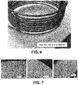
- the manufacturing technique has been progressively devolved on trial coil (1:1 to the actual dimensions), where the thickness of copper layer on the SS base tube was optimized by controlling the electro-plating process parameters. Subsequently, the thickness on the whole surface area was achieved beyond the functional requirement of 100 microns min. Further, the repeatability and consistency of the process has been ensured by the production of three similar coils. These coils have been subjected to metallographic examination, which revealed the thickness range of 150-200 microns on all the areas of coils.
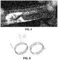
- the plated coil has been cut on several places and some cross sections have been made and the thickness has been directly measured.
- the electrical characteristics of ED plated coil have been checked and compared with respect to the pure copper coil keeping the dimensional configuration same. Result shows that inductance at 1MHz is reduced by 5%, which, if required can be compensated by using the flexibility of adjusting the frequency and therefore could be considered as the acceptable.
- the innovative methodology of realization of RF coil involves manufacturing of the RF coil from SS (grade 304L) material and provide a copper layer with the thickness sufficient to meet the RF power transmission through the skin depth.
- a prototype coil material with 8.5 turns, wounding diameter 300mm, tube diameter 8mm, thickness 1mm and pitch of 12mm has been selected and provided with electro-deposited plated copper with a targeted thickness of 100 micron copper.
- Process optimization has resulted in achieving the desired thickness of copper on SS base tube through ED plating process, which exhibited consistent results on three coils with 1: 1 dimensions.
- the requirement of layer thickness is 75microns.
- the targeted thickness was >100 microns.
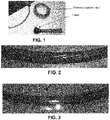
- Peel test has been performed in accordance with ASTM D3359 (Standard Test Methods for Measuring Adhesion by Tape Test) to check the adhesion of Cu layer. The test has been carried out with the help of standard cutter and pressure sensitive tape (as seen in the accompanied photograph).
- Measurement on surface roughness Measured value of surface roughness by contact type measurement tester is better than 6.3 microns Ra.
- This technology can also be utilized for other RF applications like RF transmission lines.
Landscapes
- Engineering & Computer Science (AREA)
- Chemical & Material Sciences (AREA)
- Power Engineering (AREA)
- Plasma & Fusion (AREA)
- Physics & Mathematics (AREA)
- Organic Chemistry (AREA)
- Metallurgy (AREA)
- Materials Engineering (AREA)
- Electrochemistry (AREA)
- Chemical Kinetics & Catalysis (AREA)
- Mechanical Engineering (AREA)
- Analytical Chemistry (AREA)
- Manufacturing & Machinery (AREA)
- Particle Accelerators (AREA)
Claims (5)
- Verfahren zur Herstellung einer spiralförmigen, wassergekühlten Hochfrequenz-(HF-) Spule für eine auf HF-basierende Mehrtreiber-Ionenquelle, wobei das Verfahren die Schritte umfasst:a) Herstellen eines gewickelten Rohres unter Verwendung von rostfreiem Stahl als Substratmaterial, um eine Spule auszubilden;b) Beschichten des gewickelten Rohrs, welches aus einem Stahlrohr besteht, mit einer dünnen Schicht aus Kupfer mit einer Dicke von 150 - 200 Mikrometern; undc) Verbinden einer Vielzahl von gewickelten Rohren, welche durch Schritt (a) und Schritt (b) hergestellt wurden, durch ein orbitales WIG-Schweißverfahren.
- Verfahren nach Anspruch 1, wobei das Verfahren eine vollständige Durchschweißung erreicht und zu 100% volumetrisch inspiziert werden kann.
- Verfahren nach Anspruch 1, wobei die Schicht aus Kupfer keine Porosität aufweist.
- Verfahren nach Anspruch 1, wobei die Oberflächenrauigkeit der Spule besser als 6,3 Mikrometer Ra ist.
- Verfahren nach Anspruch 1, wobei die HF-Spule für die Multitreiber-HFlonenquelle eine selbststabile Struktur ist und keine Abstandshalter zwischen den Windungen benötigt.
Applications Claiming Priority (1)
| Application Number | Priority Date | Filing Date | Title |
|---|---|---|---|
| IN201821014176 | 2018-04-13 |
Publications (2)
| Publication Number | Publication Date |
|---|---|
| EP3553797A1 EP3553797A1 (de) | 2019-10-16 |
| EP3553797B1 true EP3553797B1 (de) | 2022-04-20 |
Family
ID=62712725
Family Applications (1)
| Application Number | Title | Priority Date | Filing Date |
|---|---|---|---|
| EP18175976.2A Not-in-force EP3553797B1 (de) | 2018-04-13 | 2018-06-05 | Verfahren zur herstellung einer hochfrequenzspule mit mehrfachgetriebener hochfrequenzbasierter ionenquelle |
Country Status (2)
| Country | Link |
|---|---|
| US (1) | US11014187B2 (de) |
| EP (1) | EP3553797B1 (de) |
Families Citing this family (3)
| Publication number | Priority date | Publication date | Assignee | Title |
|---|---|---|---|---|
| EP3553797B1 (de) * | 2018-04-13 | 2022-04-20 | Institute for Plasma Research | Verfahren zur herstellung einer hochfrequenzspule mit mehrfachgetriebener hochfrequenzbasierter ionenquelle |
| US11545302B2 (en) * | 2020-01-24 | 2023-01-03 | Tokyo Electron Limited | Mold for forming a radio frequency (RF) coil for a plasma processing apparatus |
| CN112466592B (zh) * | 2020-12-15 | 2022-04-05 | 兰州科近泰基新技术有限责任公司 | 一种铜带绕制的水冷线圈及其制造工艺 |
Citations (1)
| Publication number | Priority date | Publication date | Assignee | Title |
|---|---|---|---|---|
| DE9015040U1 (de) * | 1990-10-29 | 1991-03-14 | Mannesmann AG, 4000 Düsseldorf | Induktionsspule |
Family Cites Families (11)
| Publication number | Priority date | Publication date | Assignee | Title |
|---|---|---|---|---|
| CH391879A (de) * | 1962-04-03 | 1965-05-15 | Gutor Transformatoren Ag | Flüssigkeitsgekühlte Sekundärwicklung eines Transformators für grosse Sekundärströme, insbesondere für Widerstands-Schweissmaschinen |
| US4016389A (en) * | 1975-02-21 | 1977-04-05 | White Gerald W | High rate ion plating source |
| US5396039A (en) * | 1993-11-24 | 1995-03-07 | L'air Liquide, Societe Anonyme Pour L'etude Et L'exploitation Des Procedes Georges Claude | Process for assembling piping or components by TIG welding |
| IT1273747B (it) * | 1994-02-09 | 1997-07-10 | Sirten | Avvolgimenti elettrici per induttanze e trasformatori con elementi tubolari raffreddati ad acqua e rivestimento elicoidale in piattine |
| JP3971864B2 (ja) * | 1999-04-02 | 2007-09-05 | 大陽日酸株式会社 | ステンレス鋼配管の接合方法 |
| DE10008484C2 (de) * | 2000-02-24 | 2003-07-17 | Ccr Gmbh Beschichtungstechnolo | Kühlbare Hochfrequenz-Luftspule |
| GB2361587B (en) * | 2000-04-19 | 2003-11-26 | Trikon Holdings Ltd | Method of cooling an induction coil |
| WO2011028333A1 (en) * | 2009-09-03 | 2011-03-10 | Thermal Structures, Inc. | Planetary resistance welding device and methods therefor |
| UY36783A (es) * | 2016-07-11 | 2016-08-31 | Eduardo Miguel Amaro Barboza | Cabezal magnètico para soldadura automàtica |
| EP3424635B1 (de) * | 2017-07-05 | 2022-08-31 | Institute for Plasma Research | Verfahren zur herstellung eines aktiv gekühlten beschleunigergitters mit durchgeschweisster schweissnaht |
| EP3553797B1 (de) * | 2018-04-13 | 2022-04-20 | Institute for Plasma Research | Verfahren zur herstellung einer hochfrequenzspule mit mehrfachgetriebener hochfrequenzbasierter ionenquelle |
-
2018
- 2018-06-05 EP EP18175976.2A patent/EP3553797B1/de not_active Not-in-force
- 2018-08-08 US US16/058,195 patent/US11014187B2/en not_active Expired - Fee Related
Patent Citations (1)
| Publication number | Priority date | Publication date | Assignee | Title |
|---|---|---|---|---|
| DE9015040U1 (de) * | 1990-10-29 | 1991-03-14 | Mannesmann AG, 4000 Düsseldorf | Induktionsspule |
Non-Patent Citations (1)
| Title |
|---|
| BANDYOPADHYAY M ET AL: "Two-RF-Driver-Based Negative Ion Source for Fusion R&D", IEEE TRANSACTIONS ON PLASMA SCIENCE, IEEE SERVICE CENTER, PISCATAWAY, NJ, US, vol. 40, no. 10, 1 October 2012 (2012-10-01), pages 2767 - 2772, XP011466811, ISSN: 0093-3813, DOI: 10.1109/TPS.2012.2211896 * |
Also Published As
| Publication number | Publication date |
|---|---|
| US20190314922A1 (en) | 2019-10-17 |
| EP3553797A1 (de) | 2019-10-16 |
| US11014187B2 (en) | 2021-05-25 |
Similar Documents
| Publication | Publication Date | Title |
|---|---|---|
| EP3553797B1 (de) | Verfahren zur herstellung einer hochfrequenzspule mit mehrfachgetriebener hochfrequenzbasierter ionenquelle | |
| EP3232042B1 (de) | Verfahren zur herstellung einer brennkammer eines raketentriebwerks, brennkammer eines raketentriebwerks und raketentriebwerk | |
| US20110132973A1 (en) | Method of manufacturing high-heat-load equipment by metallurgically joining carbon material with copper-alloy material | |
| JP6340403B2 (ja) | 容易にアクセス可能な深温冷凍nmrシム配置 | |
| Kumar et al. | A new vacuum brazing route for niobium-316L stainless steel transition joints for superconducting RF cavities | |
| Kumar et al. | Process development for vacuum brazed niobium–316L stainless steel transition joints for superconducting cavities | |
| CN106181015A (zh) | 一种聚变堆包层附钨u型含流道第一壁部件的制造工艺 | |
| US5615826A (en) | Method for welding beryllium | |
| CN111584400B (zh) | 一种干法刻蚀半导体通气腔体及其制备方法 | |
| CN120199673A (zh) | 陶瓷基座 | |
| Tong-Ming et al. | Fabrication of the high power input coupler for BEPCII superconducting cavities | |
| Ghodke et al. | Machining and brazing of accelerating RF cavity | |
| Park et al. | The fabrication of the prototype β= 0.12 half-wave resonator at the Rare Isotope Science Project (RISP) | |
| Turchi et al. | Design, fabrication, and operation of a high-energy liner implosion experiment at 16 megamperes | |
| CN112222777B (zh) | 一种热核聚变堆高钎着率复合管轧制钎焊连接方法 | |
| Barrière et al. | JACOW: HOM Couplers and RF Antennas for HL-LHC Crab Cavities: Developments for Manufacturing | |
| Langeslag et al. | Extensive characterisation of copper-clad plates, bonded by the explosive technique, for ITER electrical joints | |
| Ridzon et al. | Manufacturing Process Development for Joining GRCop-84 and-42 Alloys for DIII-D LHCD | |
| CN120199672B (zh) | 陶瓷基座 | |
| Verdú-Andrés | Beam-Impedance Considerations for the EIC HSR Screen | |
| CN110091130A (zh) | 一种磁重联镍线圈靶制造方法 | |
| US8712490B2 (en) | Conductor for transmitting electrical power | |
| Kato et al. | DEVELOPMENT OF AN L-BAND RF GUN FOR HIGH-DUTY-CYCLE OPERATION | |
| US20220371093A1 (en) | Method of manufacturing additively manufactured object | |
| Heikinheimo et al. | Dielectric window for reactor like ICRF vacuum transmission line |
Legal Events
| Date | Code | Title | Description |
|---|---|---|---|
| PUAI | Public reference made under article 153(3) epc to a published international application that has entered the european phase |
Free format text: ORIGINAL CODE: 0009012 |
|
| STAA | Information on the status of an ep patent application or granted ep patent |
Free format text: STATUS: THE APPLICATION HAS BEEN PUBLISHED |
|
| AK | Designated contracting states |
Kind code of ref document: A1 Designated state(s): AL AT BE BG CH CY CZ DE DK EE ES FI FR GB GR HR HU IE IS IT LI LT LU LV MC MK MT NL NO PL PT RO RS SE SI SK SM TR |
|
| AX | Request for extension of the european patent |
Extension state: BA ME |
|
| STAA | Information on the status of an ep patent application or granted ep patent |
Free format text: STATUS: REQUEST FOR EXAMINATION WAS MADE |
|
| 17P | Request for examination filed |
Effective date: 20200428 |
|
| RBV | Designated contracting states (corrected) |
Designated state(s): AL AT BE BG CH CY CZ DE DK EE ES FI FR GB GR HR HU IE IS IT LI LT LU LV MC MK MT NL NO PL PT RO RS SE SI SK SM TR |
|
| GRAP | Despatch of communication of intention to grant a patent |
Free format text: ORIGINAL CODE: EPIDOSNIGR1 |
|
| STAA | Information on the status of an ep patent application or granted ep patent |
Free format text: STATUS: GRANT OF PATENT IS INTENDED |
|
| INTG | Intention to grant announced |
Effective date: 20220105 |
|
| RIN1 | Information on inventor provided before grant (corrected) |
Inventor name: PARMAR, DEEPAK KUMAR Inventor name: MUVVALA, VENKATA NAGARAJU Inventor name: PATEL, MILIND KUMAR Inventor name: GAHLAUT, AGRAJIT Inventor name: BANDYOPADHYAY, MAINAK Inventor name: CHAKRABORTY, ARUN KUMAR Inventor name: MOULI, ROTTI CHANDRA Inventor name: JOSHI, JAYDEEP |
|
| RIN1 | Information on inventor provided before grant (corrected) |
Inventor name: PARMAR, DEEPAK KUMAR Inventor name: MUVVALA, VENKATA NAGARAJU Inventor name: PATEL, MILIND KUMAR Inventor name: GAHLAUT, AGRAJIT Inventor name: BANDYOPADHYAY, MAINAK Inventor name: CHAKRABORTY, ARUN KUMAR Inventor name: ROTTI, CHANDRAMOULI Inventor name: JOSHI, JAYDEEP |
|
| GRAS | Grant fee paid |
Free format text: ORIGINAL CODE: EPIDOSNIGR3 |
|
| GRAA | (expected) grant |
Free format text: ORIGINAL CODE: 0009210 |
|
| STAA | Information on the status of an ep patent application or granted ep patent |
Free format text: STATUS: THE PATENT HAS BEEN GRANTED |
|
| AK | Designated contracting states |
Kind code of ref document: B1 Designated state(s): AL AT BE BG CH CY CZ DE DK EE ES FI FR GB GR HR HU IE IS IT LI LT LU LV MC MK MT NL NO PL PT RO RS SE SI SK SM TR |
|
| REG | Reference to a national code |
Ref country code: GB Ref legal event code: FG4D |
|
| REG | Reference to a national code |
Ref country code: CH Ref legal event code: EP |
|
| REG | Reference to a national code |
Ref country code: IE Ref legal event code: FG4D |
|
| REG | Reference to a national code |
Ref country code: DE Ref legal event code: R096 Ref document number: 602018034024 Country of ref document: DE |
|
| REG | Reference to a national code |
Ref country code: AT Ref legal event code: REF Ref document number: 1485847 Country of ref document: AT Kind code of ref document: T Effective date: 20220515 |
|
| PGFP | Annual fee paid to national office [announced via postgrant information from national office to epo] |
Ref country code: IT Payment date: 20220628 Year of fee payment: 5 |
|
| REG | Reference to a national code |
Ref country code: LT Ref legal event code: MG9D |
|
| REG | Reference to a national code |
Ref country code: NL Ref legal event code: MP Effective date: 20220420 |
|
| REG | Reference to a national code |
Ref country code: AT Ref legal event code: MK05 Ref document number: 1485847 Country of ref document: AT Kind code of ref document: T Effective date: 20220420 |
|
| PG25 | Lapsed in a contracting state [announced via postgrant information from national office to epo] |
Ref country code: NL Free format text: LAPSE BECAUSE OF FAILURE TO SUBMIT A TRANSLATION OF THE DESCRIPTION OR TO PAY THE FEE WITHIN THE PRESCRIBED TIME-LIMIT Effective date: 20220420 |
|
| PGFP | Annual fee paid to national office [announced via postgrant information from national office to epo] |
Ref country code: FR Payment date: 20220628 Year of fee payment: 5 |
|
| PG25 | Lapsed in a contracting state [announced via postgrant information from national office to epo] |
Ref country code: SE Free format text: LAPSE BECAUSE OF FAILURE TO SUBMIT A TRANSLATION OF THE DESCRIPTION OR TO PAY THE FEE WITHIN THE PRESCRIBED TIME-LIMIT Effective date: 20220420 Ref country code: PT Free format text: LAPSE BECAUSE OF FAILURE TO SUBMIT A TRANSLATION OF THE DESCRIPTION OR TO PAY THE FEE WITHIN THE PRESCRIBED TIME-LIMIT Effective date: 20220822 Ref country code: NO Free format text: LAPSE BECAUSE OF FAILURE TO SUBMIT A TRANSLATION OF THE DESCRIPTION OR TO PAY THE FEE WITHIN THE PRESCRIBED TIME-LIMIT Effective date: 20220720 Ref country code: LT Free format text: LAPSE BECAUSE OF FAILURE TO SUBMIT A TRANSLATION OF THE DESCRIPTION OR TO PAY THE FEE WITHIN THE PRESCRIBED TIME-LIMIT Effective date: 20220420 Ref country code: HR Free format text: LAPSE BECAUSE OF FAILURE TO SUBMIT A TRANSLATION OF THE DESCRIPTION OR TO PAY THE FEE WITHIN THE PRESCRIBED TIME-LIMIT Effective date: 20220420 Ref country code: GR Free format text: LAPSE BECAUSE OF FAILURE TO SUBMIT A TRANSLATION OF THE DESCRIPTION OR TO PAY THE FEE WITHIN THE PRESCRIBED TIME-LIMIT Effective date: 20220721 Ref country code: FI Free format text: LAPSE BECAUSE OF FAILURE TO SUBMIT A TRANSLATION OF THE DESCRIPTION OR TO PAY THE FEE WITHIN THE PRESCRIBED TIME-LIMIT Effective date: 20220420 Ref country code: ES Free format text: LAPSE BECAUSE OF FAILURE TO SUBMIT A TRANSLATION OF THE DESCRIPTION OR TO PAY THE FEE WITHIN THE PRESCRIBED TIME-LIMIT Effective date: 20220420 Ref country code: BG Free format text: LAPSE BECAUSE OF FAILURE TO SUBMIT A TRANSLATION OF THE DESCRIPTION OR TO PAY THE FEE WITHIN THE PRESCRIBED TIME-LIMIT Effective date: 20220720 Ref country code: AT Free format text: LAPSE BECAUSE OF FAILURE TO SUBMIT A TRANSLATION OF THE DESCRIPTION OR TO PAY THE FEE WITHIN THE PRESCRIBED TIME-LIMIT Effective date: 20220420 |
|
| PGFP | Annual fee paid to national office [announced via postgrant information from national office to epo] |
Ref country code: DE Payment date: 20220620 Year of fee payment: 5 |
|
| PG25 | Lapsed in a contracting state [announced via postgrant information from national office to epo] |
Ref country code: RS Free format text: LAPSE BECAUSE OF FAILURE TO SUBMIT A TRANSLATION OF THE DESCRIPTION OR TO PAY THE FEE WITHIN THE PRESCRIBED TIME-LIMIT Effective date: 20220420 Ref country code: PL Free format text: LAPSE BECAUSE OF FAILURE TO SUBMIT A TRANSLATION OF THE DESCRIPTION OR TO PAY THE FEE WITHIN THE PRESCRIBED TIME-LIMIT Effective date: 20220420 Ref country code: LV Free format text: LAPSE BECAUSE OF FAILURE TO SUBMIT A TRANSLATION OF THE DESCRIPTION OR TO PAY THE FEE WITHIN THE PRESCRIBED TIME-LIMIT Effective date: 20220420 Ref country code: IS Free format text: LAPSE BECAUSE OF FAILURE TO SUBMIT A TRANSLATION OF THE DESCRIPTION OR TO PAY THE FEE WITHIN THE PRESCRIBED TIME-LIMIT Effective date: 20220820 |
|
| REG | Reference to a national code |
Ref country code: DE Ref legal event code: R097 Ref document number: 602018034024 Country of ref document: DE |
|
| PG25 | Lapsed in a contracting state [announced via postgrant information from national office to epo] |
Ref country code: SM Free format text: LAPSE BECAUSE OF FAILURE TO SUBMIT A TRANSLATION OF THE DESCRIPTION OR TO PAY THE FEE WITHIN THE PRESCRIBED TIME-LIMIT Effective date: 20220420 Ref country code: SK Free format text: LAPSE BECAUSE OF FAILURE TO SUBMIT A TRANSLATION OF THE DESCRIPTION OR TO PAY THE FEE WITHIN THE PRESCRIBED TIME-LIMIT Effective date: 20220420 Ref country code: RO Free format text: LAPSE BECAUSE OF FAILURE TO SUBMIT A TRANSLATION OF THE DESCRIPTION OR TO PAY THE FEE WITHIN THE PRESCRIBED TIME-LIMIT Effective date: 20220420 Ref country code: MC Free format text: LAPSE BECAUSE OF FAILURE TO SUBMIT A TRANSLATION OF THE DESCRIPTION OR TO PAY THE FEE WITHIN THE PRESCRIBED TIME-LIMIT Effective date: 20220420 Ref country code: EE Free format text: LAPSE BECAUSE OF FAILURE TO SUBMIT A TRANSLATION OF THE DESCRIPTION OR TO PAY THE FEE WITHIN THE PRESCRIBED TIME-LIMIT Effective date: 20220420 Ref country code: DK Free format text: LAPSE BECAUSE OF FAILURE TO SUBMIT A TRANSLATION OF THE DESCRIPTION OR TO PAY THE FEE WITHIN THE PRESCRIBED TIME-LIMIT Effective date: 20220420 Ref country code: CZ Free format text: LAPSE BECAUSE OF FAILURE TO SUBMIT A TRANSLATION OF THE DESCRIPTION OR TO PAY THE FEE WITHIN THE PRESCRIBED TIME-LIMIT Effective date: 20220420 |
|
| REG | Reference to a national code |
Ref country code: CH Ref legal event code: PL |
|
| REG | Reference to a national code |
Ref country code: BE Ref legal event code: MM Effective date: 20220630 |
|
| PLBE | No opposition filed within time limit |
Free format text: ORIGINAL CODE: 0009261 |
|
| STAA | Information on the status of an ep patent application or granted ep patent |
Free format text: STATUS: NO OPPOSITION FILED WITHIN TIME LIMIT |
|
| 26N | No opposition filed |
Effective date: 20230123 |
|
| GBPC | Gb: european patent ceased through non-payment of renewal fee |
Effective date: 20220720 |
|
| PG25 | Lapsed in a contracting state [announced via postgrant information from national office to epo] |
Ref country code: AL Free format text: LAPSE BECAUSE OF FAILURE TO SUBMIT A TRANSLATION OF THE DESCRIPTION OR TO PAY THE FEE WITHIN THE PRESCRIBED TIME-LIMIT Effective date: 20220420 |
|
| PG25 | Lapsed in a contracting state [announced via postgrant information from national office to epo] |
Ref country code: LU Free format text: LAPSE BECAUSE OF NON-PAYMENT OF DUE FEES Effective date: 20220605 Ref country code: LI Free format text: LAPSE BECAUSE OF NON-PAYMENT OF DUE FEES Effective date: 20220630 Ref country code: IE Free format text: LAPSE BECAUSE OF NON-PAYMENT OF DUE FEES Effective date: 20220605 Ref country code: CH Free format text: LAPSE BECAUSE OF NON-PAYMENT OF DUE FEES Effective date: 20220630 |
|
| PG25 | Lapsed in a contracting state [announced via postgrant information from national office to epo] |
Ref country code: SI Free format text: LAPSE BECAUSE OF FAILURE TO SUBMIT A TRANSLATION OF THE DESCRIPTION OR TO PAY THE FEE WITHIN THE PRESCRIBED TIME-LIMIT Effective date: 20220420 Ref country code: GB Free format text: LAPSE BECAUSE OF NON-PAYMENT OF DUE FEES Effective date: 20220720 Ref country code: BE Free format text: LAPSE BECAUSE OF NON-PAYMENT OF DUE FEES Effective date: 20220630 |
|
| REG | Reference to a national code |
Ref country code: DE Ref legal event code: R119 Ref document number: 602018034024 Country of ref document: DE |
|
| PG25 | Lapsed in a contracting state [announced via postgrant information from national office to epo] |
Ref country code: HU Free format text: LAPSE BECAUSE OF FAILURE TO SUBMIT A TRANSLATION OF THE DESCRIPTION OR TO PAY THE FEE WITHIN THE PRESCRIBED TIME-LIMIT; INVALID AB INITIO Effective date: 20180605 |
|
| PG25 | Lapsed in a contracting state [announced via postgrant information from national office to epo] |
Ref country code: MK Free format text: LAPSE BECAUSE OF FAILURE TO SUBMIT A TRANSLATION OF THE DESCRIPTION OR TO PAY THE FEE WITHIN THE PRESCRIBED TIME-LIMIT Effective date: 20220420 Ref country code: DE Free format text: LAPSE BECAUSE OF NON-PAYMENT OF DUE FEES Effective date: 20240103 Ref country code: CY Free format text: LAPSE BECAUSE OF FAILURE TO SUBMIT A TRANSLATION OF THE DESCRIPTION OR TO PAY THE FEE WITHIN THE PRESCRIBED TIME-LIMIT Effective date: 20220420 |
|
| PG25 | Lapsed in a contracting state [announced via postgrant information from national office to epo] |
Ref country code: FR Free format text: LAPSE BECAUSE OF NON-PAYMENT OF DUE FEES Effective date: 20230630 |
|
| PG25 | Lapsed in a contracting state [announced via postgrant information from national office to epo] |
Ref country code: IT Free format text: LAPSE BECAUSE OF NON-PAYMENT OF DUE FEES Effective date: 20230605 |
|
| PG25 | Lapsed in a contracting state [announced via postgrant information from national office to epo] |
Ref country code: MT Free format text: LAPSE BECAUSE OF FAILURE TO SUBMIT A TRANSLATION OF THE DESCRIPTION OR TO PAY THE FEE WITHIN THE PRESCRIBED TIME-LIMIT Effective date: 20220420 |
|
| PG25 | Lapsed in a contracting state [announced via postgrant information from national office to epo] |
Ref country code: BG Free format text: LAPSE BECAUSE OF FAILURE TO SUBMIT A TRANSLATION OF THE DESCRIPTION OR TO PAY THE FEE WITHIN THE PRESCRIBED TIME-LIMIT Effective date: 20220420 |
|
| PG25 | Lapsed in a contracting state [announced via postgrant information from national office to epo] |
Ref country code: BG Free format text: LAPSE BECAUSE OF FAILURE TO SUBMIT A TRANSLATION OF THE DESCRIPTION OR TO PAY THE FEE WITHIN THE PRESCRIBED TIME-LIMIT Effective date: 20220420 |
|
| PG25 | Lapsed in a contracting state [announced via postgrant information from national office to epo] |
Ref country code: TR Free format text: LAPSE BECAUSE OF FAILURE TO SUBMIT A TRANSLATION OF THE DESCRIPTION OR TO PAY THE FEE WITHIN THE PRESCRIBED TIME-LIMIT Effective date: 20220420 |