EP3553780B1 - Signal feature extraction apparatus, signal feature extraction method, and program - Google Patents
Signal feature extraction apparatus, signal feature extraction method, and program Download PDFInfo
- Publication number
- EP3553780B1 EP3553780B1 EP17878298.3A EP17878298A EP3553780B1 EP 3553780 B1 EP3553780 B1 EP 3553780B1 EP 17878298 A EP17878298 A EP 17878298A EP 3553780 B1 EP3553780 B1 EP 3553780B1
- Authority
- EP
- European Patent Office
- Prior art keywords
- peak value
- feature
- value
- output signal
- feature peak
- Prior art date
- Legal status (The legal status is an assumption and is not a legal conclusion. Google has not performed a legal analysis and makes no representation as to the accuracy of the status listed.)
- Active
Links
Images

Classifications
-
- A—HUMAN NECESSITIES
- A61—MEDICAL OR VETERINARY SCIENCE; HYGIENE
- A61B—DIAGNOSIS; SURGERY; IDENTIFICATION
- A61B5/00—Measuring for diagnostic purposes; Identification of persons
- A61B5/24—Detecting, measuring or recording bioelectric or biomagnetic signals of the body or parts thereof
- A61B5/316—Modalities, i.e. specific diagnostic methods
- A61B5/318—Heart-related electrical modalities, e.g. electrocardiography [ECG]
- A61B5/346—Analysis of electrocardiograms
- A61B5/349—Detecting specific parameters of the electrocardiograph cycle
- A61B5/352—Detecting R peaks, e.g. for synchronising diagnostic apparatus; Estimating R-R interval
-
- G—PHYSICS
- G10—MUSICAL INSTRUMENTS; ACOUSTICS
- G10L—SPEECH ANALYSIS TECHNIQUES OR SPEECH SYNTHESIS; SPEECH RECOGNITION; SPEECH OR VOICE PROCESSING TECHNIQUES; SPEECH OR AUDIO CODING OR DECODING
- G10L25/00—Speech or voice analysis techniques not restricted to a single one of groups G10L15/00 - G10L21/00
- G10L25/90—Pitch determination of speech signals
-
- A—HUMAN NECESSITIES
- A61—MEDICAL OR VETERINARY SCIENCE; HYGIENE
- A61B—DIAGNOSIS; SURGERY; IDENTIFICATION
- A61B5/00—Measuring for diagnostic purposes; Identification of persons
- A61B5/02—Detecting, measuring or recording for evaluating the cardiovascular system, e.g. pulse, heart rate, blood pressure or blood flow
- A61B5/0205—Simultaneously evaluating both cardiovascular conditions and different types of body conditions, e.g. heart and respiratory condition
-
- A—HUMAN NECESSITIES
- A61—MEDICAL OR VETERINARY SCIENCE; HYGIENE
- A61B—DIAGNOSIS; SURGERY; IDENTIFICATION
- A61B5/00—Measuring for diagnostic purposes; Identification of persons
- A61B5/08—Measuring devices for evaluating the respiratory organs
- A61B5/0816—Measuring devices for examining respiratory frequency
-
- A—HUMAN NECESSITIES
- A61—MEDICAL OR VETERINARY SCIENCE; HYGIENE
- A61B—DIAGNOSIS; SURGERY; IDENTIFICATION
- A61B5/00—Measuring for diagnostic purposes; Identification of persons
- A61B5/72—Signal processing specially adapted for physiological signals or for diagnostic purposes
-
- A—HUMAN NECESSITIES
- A61—MEDICAL OR VETERINARY SCIENCE; HYGIENE
- A61B—DIAGNOSIS; SURGERY; IDENTIFICATION
- A61B5/00—Measuring for diagnostic purposes; Identification of persons
- A61B5/72—Signal processing specially adapted for physiological signals or for diagnostic purposes
- A61B5/7235—Details of waveform analysis
- A61B5/725—Details of waveform analysis using specific filters therefor, e.g. Kalman or adaptive filters
-
- A—HUMAN NECESSITIES
- A61—MEDICAL OR VETERINARY SCIENCE; HYGIENE
- A61B—DIAGNOSIS; SURGERY; IDENTIFICATION
- A61B5/00—Measuring for diagnostic purposes; Identification of persons
- A61B5/02—Detecting, measuring or recording for evaluating the cardiovascular system, e.g. pulse, heart rate, blood pressure or blood flow
- A61B5/024—Measuring pulse rate or heart rate
-
- A—HUMAN NECESSITIES
- A61—MEDICAL OR VETERINARY SCIENCE; HYGIENE
- A61B—DIAGNOSIS; SURGERY; IDENTIFICATION
- A61B5/00—Measuring for diagnostic purposes; Identification of persons
- A61B5/103—Measuring devices for testing the shape, pattern, colour, size or movement of the body or parts thereof, for diagnostic purposes
- A61B5/11—Measuring movement of the entire body or parts thereof, e.g. head or hand tremor or mobility of a limb
- A61B5/1102—Ballistocardiography
-
- A—HUMAN NECESSITIES
- A61—MEDICAL OR VETERINARY SCIENCE; HYGIENE
- A61B—DIAGNOSIS; SURGERY; IDENTIFICATION
- A61B5/00—Measuring for diagnostic purposes; Identification of persons
- A61B5/72—Signal processing specially adapted for physiological signals or for diagnostic purposes
- A61B5/7203—Signal processing specially adapted for physiological signals or for diagnostic purposes for noise prevention, reduction or removal
-
- A—HUMAN NECESSITIES
- A61—MEDICAL OR VETERINARY SCIENCE; HYGIENE
- A61B—DIAGNOSIS; SURGERY; IDENTIFICATION
- A61B5/00—Measuring for diagnostic purposes; Identification of persons
- A61B5/72—Signal processing specially adapted for physiological signals or for diagnostic purposes
- A61B5/7235—Details of waveform analysis
- A61B5/7253—Details of waveform analysis characterised by using transforms
- A61B5/726—Details of waveform analysis characterised by using transforms using Wavelet transforms
-
- G—PHYSICS
- G10—MUSICAL INSTRUMENTS; ACOUSTICS
- G10L—SPEECH ANALYSIS TECHNIQUES OR SPEECH SYNTHESIS; SPEECH RECOGNITION; SPEECH OR VOICE PROCESSING TECHNIQUES; SPEECH OR AUDIO CODING OR DECODING
- G10L25/00—Speech or voice analysis techniques not restricted to a single one of groups G10L15/00 - G10L21/00
- G10L25/03—Speech or voice analysis techniques not restricted to a single one of groups G10L15/00 - G10L21/00 characterised by the type of extracted parameters
- G10L25/18—Speech or voice analysis techniques not restricted to a single one of groups G10L15/00 - G10L21/00 characterised by the type of extracted parameters the extracted parameters being spectral information of each sub-band
Definitions
- the present invention relates to a technique for extracting features of a signal waveform of an acoustic signal, a biological signal, or the like.
- a filter bank composed of a group of band-pass filters having different center frequencies and band widths (for example, see non-patent literature 1).
- a filter bank composed of a group of band-pass filters having different center frequencies and band widths
- an output signal of a band-pass filter (hereinafter also referred to as a feature extraction filter) having an impulse response highly correlated with the waveform pattern takes a peak value (hereinafter also referred to as a feature peak value) in synchronization with an appearance of a target waveform pattern.
- RRI R-R Interval
- RRI R-R Interval
- Patent literature 1 relates to apparatus and methods for determining precise times of occurrence of R-waves in an electrocardiogram (ECG) signal of a patient.
- ECG electrocardiogram
- Samples of the patient's ECG signal are accumulated and an ECG window comprising a predetermined number of the samples is defined.
- the patient's blood pressure signal is processed to detect systoles and the ECG window has a predetermined time relationship to detected systoles.
- the ECG signal is first processed to approximate the times of occurrence of R-waves and the ECG window is defined to have a predetermined time relationship to the approximated R-wave times.
- ECG signal samples within the ECG window are processed to determine a maximum and the time of occurrence of the maximum is stored as the time of an R-wave event.
- Patent literature 1 US 6 161 037 A .
- Non-patent literature 1 M. Vetterli and C. Herley, "Wavelets and filter banks: theory and design,” in IEEE Transactions on Signal Processing, vol. 40, no. 9, pp. 2207-2232, Sep 1992 .
- the output of the feature extraction filter may show peaks other than a desired feature peak due to factors such as noise being mixed in with a signal to be analyzed. This may result in an erroneous peak position causing inappropriate RRI for feature analysis.
- An object of the present invention is to provide a signal feature extraction technique that can accurately identify an appearance position of a desired waveform pattern output from a feature extraction filter with respect to a signal to be analyzed without being influenced by noise or the like and output it as a signal feature.
- a signal feature extraction apparatus of a first aspect of the present invention is a signal feature extraction apparatus that extracts a feature peak value of a waveform pattern from an output signal of a feature extraction filter that extracts a waveform pattern of a biological signal, comprising a local maximum value detection part that stores a time index and a value of the output signal when an absolute value of the output signal is equal to or more than a predetermined threshold value and takes a local maximum value; and a feature peak value selection part that selects a feature peak value on the basis of a difference between a time interval between the stored time index and a time index of a feature peak value selected immediately before and an average time interval at which the feature peak value can occur, and a difference between a logarithmic amplitude and phase of the output signal corresponding to the stored time index and an average logarithmic amplitude and average phase that the feature peak value can take.
- a signal feature extraction apparatus of a second aspect of the present invention is a signal feature extraction apparatus that extracts a feature peak value of a waveform pattern from an output signal of a feature extraction filter that extracts a waveform pattern of a biological signal, comprising a local maximum value detection part that stores a time index and a value of the output signal when an absolute value of the output signal is equal to or more than a predetermined threshold value and takes a local maximum value; and a feature peak value selection part that selects a feature peak value on the basis of a difference between a time interval between the stored time index and a time index of a feature peak value selected immediately before and an average time interval at which the feature peak value can occur, a difference between an amplitude of the output signal corresponding to the stored time index and an average amplitude the feature peak value can take, and a difference between a phase of the output signal corresponding to the stored time index and an average phase the feature peak value can take.
- an analysis system including at least one or more feature extraction filters (for example, band-pass filters, wavelets, or other filters with nonlinear nature).
- feature extraction filters for example, band-pass filters, wavelets, or other filters with nonlinear nature.
- the feature extraction filters are limited to linear or nonlinear filters that output as an output signal a complex signal having a real part and an imaginary part mutually convertible (or approximately convertible) by Hilbert transform.
- the present invention is a signal feature extraction technique for selecting a peak value desired to be originally extracted as a feature peak value from peak values of an absolute value
- a signal feature extraction method according to the invention will be described below.
- the average time interval ⁇ T when the feature peak value appears, average logarithmic amplitude log_A, and average phase ⁇ may be given fixed values or may be sequentially updated on the basis of information on the feature peak value P(n k ) detected newly by the processing of (4) (and past information). If it is updated whenever a new feature peak value P(n k ) is selected, for example, it can be updated by a formula (3).
- ⁇ 1, ⁇ 2, and ⁇ 3 are adjustment coefficients for taking a value in the range of 0 to 1 and adjusting a weighted average with past estimated values.
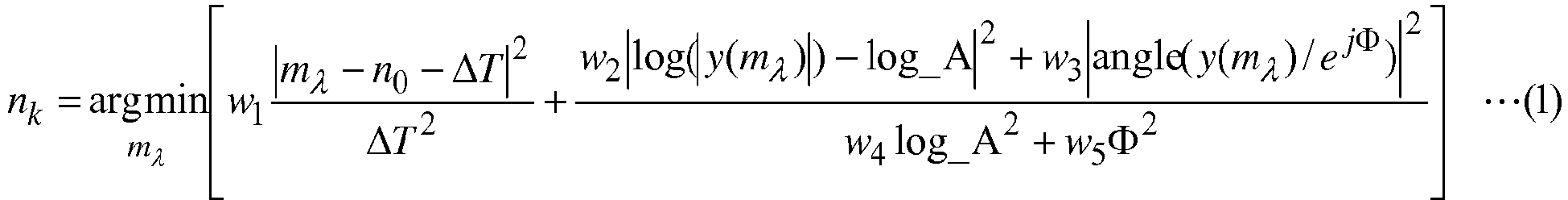
- the validity of the detected feature peak value P(n k ) can be evaluated by the magnitude of an error E calculated by a formula (4).
- E min m ⁇ w 1 m ⁇ ⁇ n 0 ⁇ ⁇ T 2 ⁇ T 2 + w 2 log y m ⁇ ⁇ log _ A 2 + w 3 angle y m ⁇ / e j ⁇ 2 w 4 log _ A 2 + w 5 ⁇ 2
- values of the weighting factors w 1 , w 2 , w 3 , w 4 , and w 5 in the formula (1) and the adjustment coefficients ⁇ 1 , ⁇ 2 , and ⁇ 3 in the formula (3) may be switched and given. Control can be performed, for example, when the magnitude of the error E is smaller, the values of the adjustment coefficients ⁇ 1 , ⁇ 2 , and ⁇ 3 can be given smaller values and the degree of reflection of latest information can be increased.
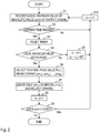
- a signal feature extraction apparatus 10 of the embodiment includes a local maximum value detection part 1, a feature peak value selection part 2, and a local maximum value rejection part 3 as shown in Fig. 1 .
- the signal feature extraction apparatus 10 performs processing of steps shown in Fig. 2 and thereby implements a signal feature extraction method of the embodiment.
- the signal feature extraction apparatus 10 is a special apparatus formed, for example, by causing a known or dedicated computer including a central processing unit (CPU), a main storage device (RAM: Random Access Memory), and the like to read in a special program.
- the signal feature extraction apparatus 10 performs the processing, for example, under control of the central processing unit.
- Data input into the signal feature extraction apparatus 10 or data obtained by the processing is stored, for example, in the main storage device, and the data stored in the main storage device is read out on demand, and used for other processing.
- At least part of processing parts of the signal feature extraction apparatus 10 may be configured by hardware such as an integrated circuit.
- the local maximum value detection part 1 receives an output signal y(n) when an input signal x(n) to be analyzed is input into a feature extraction filter, and stores a value of the output signal y(n) together with the time index m ⁇ when an absolute value
- of the output signal y(n) is equal to or more than a predetermined threshold value and takes a local maximum value, in which a time index at that time is denoted by m ⁇ n.
- step S2 the local maximum value detection part 1 determines whether a timer that measures a time when the local maximum value detection processing is being performed indicates that a certain time has passed. If the certain time has not passed, in step S10, 1 is added to the time index n, and the processing of step S1 is executed again. If the certain time has passed, the timer is reset in step S3, and the processing proceeds to step S4.
- step S4 the local maximum value detection part 1 determines whether the local maximum value detected in step S1 exists. If the local maximum value is not detected, the local maximum value detection part 1 updates a time index n k and a serial number k of the most recently selected feature peak value P(n k-1 ) to k ⁇ k+1, n k ⁇ n k-1 + ⁇ T in step S5. If the local maximum value is detected, the local maximum value detection part 1 transmits local maximum values y(m 1 ), y(m 2 ), ..., y(m N ) to the feature peak value selection part 2, and the processing proceeds to step S6.
- the feature peak value selection part 2 receives the stored local maximum values y(m 1 ), y(m 2 ), ..., y(m N ) of the output signal from the local maximum value detection part 1, and selects a feature peak value P(n k ) on the basis of differences from the average time interval ⁇ T, average logarithmic amplitude log_A, and average phase ⁇ of past feature peak values. Specifically, the feature peak value P(n k ) is calculated by the above-described formulas (1) and (2). The feature peak value P(n k ) and its time index n k are transmitted to the local maximum value rejection part 3.
- step S7 the local maximum value rejection part 3 leaves the local maximum value y(m ⁇ ) corresponding to a time index which is n k ⁇ m ⁇ among the stored local maximum values y(m 1 ), y(m 2 ), ..., y(m N ) of the output signal and rejects the rest. Then, in step S8, the serial number k is updated to k ⁇ k+1.
- step S9 it is determined whether an input signal x(n+1) of a next time n+1 exists. If it exists, 1 is added to the time index n in step 10, and the processing of steps S1 to S9 is executed again. If it does not exist, the processing is terminated.
- a feature peak value is simultaneously and comprehensively evaluated for a plurality of candidates for the feature peak value regarding adequacy of the time interval and the magnitude of amplitude value with relative to the feature peak values detected in the past and adequacy of the phase angle (the phase angle is different if the waveform pattern is different even if equivalent frequency components are included), and it is possible to detect the feature peak value more accurately.
- Points of the invention are summarized as follows.
- an output signal obtained when a signal in which a similar waveform pattern (feature) is continuously repeated is input into an analysis system including at least one or more feature extraction filters (also including, for example, band-pass filters, wavelets, or other filters with nonlinear nature)
- an output signal of a feature extraction filter highly correlated with the waveform pattern takes a peak value in synchronization with an appearance of features of a target waveform pattern.
- peak values other than a desired peak value such as noise or leakage of other waveform patterns are observed from the output signal of the same feature extraction filter.
- the invention is one method for selecting a desired peak value (feature peak value) that is desired to be originally acquired from peak values observed in an output signal of a certain feature extraction filter.
- the most likely feature peak value is selected from a plurality of candidate peak values by comprehensively determining whether the following three hypotheses are satisfied: regularity in the time interval with past feature peak values (appearing at approximately constant intervals); consistency of the magnitude of the amplitude value (the magnitude of peak values is approximately equal); and consistency of the phase angle (not only frequency characteristics but also patterns as time waveforms are similar).
- the invention selects as the desired peak value a feature peak value that is the smallest in difference between a time interval between an observed peak value and an immediately before feature peak value and an average time interval at which a feature peak value can occur, difference between the amplitude of the observed peak value and the average amplitude that the feature peak value can take, and difference between the phase of the observed peak value and the average phase that the feature peak value can take.
- the formula (4) can be used, which corresponds to, by taking logarithm of the stored complex output signal, obtaining features of a complex number having logarithmic amplitude in the real part and phase information in the imaginary part, and evaluating differences in amplitude and phase uniformly as a whole.
- Input signals to be analyzed in the invention are biological signals (for example, an electrocardiogram (ECG, EKG), a pulse wave measured by photoplethysmogram (PPG) or the like, and a respiration curve) related to a physiological phenomenon having arbitrary periodicity including an acoustic signal or heartbeat, pulse, and breathing.
- the input signals to be analyzed repeat a local waveform pattern having substantially the same size and shape at almost periodic intervals.
- An output signal of a filter having a high correlation with such a characteristic waveform pattern takes a peak value selectable according to the present invention in synchronization with the appearance of the waveform pattern.
- a measurement method of a biological signal is not questioned.
- an object may be an electrocardiogram which is a method for measuring an electric activity associated with the heartbeat or it may be a seismocardiography (SCG) or ballistocardiography (BCG) which measures vibration of skin caused by the heartbeat with an accelerometer.
- SCG seismocardiography
- BCG ballistocardiography
- Biological signals not described above may also be included in the analysis objects as long as they have the above characteristics.
- the program describing the processing contents can be recorded on a computer-readable recording medium.
- the computer-readable recording medium may be any medium, for example, a magnetic recording device, an optical disc, a magneto-optical recording medium, and a semiconductor memory.
- Distribution of this program is carried out, for example, by selling, transferring, and renting a portable recording medium such as a DVD, CD-ROM, or a flash drive in which the program is recorded. Otherwise, the program can be pre-installed in arbitrary recording medium through the manufacturing process in a factory. Furthermore, the program may be stored in a storage device of a sever computer, and the program may be distributed by transferring the program from the server computer to another computer via a network.
- a computer that executes such a program for example, stores the program recorded in the portable recording medium or the program transferred from the server computer in its own storage device.
- the computer reads the program stored in its own recording medium and executes the processing according to the read program.
- the computer may read the program directory from the portable recording medium and execute the processing according to the program, or may sequentially execute, each time a program is transferred from the server computer to the computer, processing according to the received program.
- the above-described processing may be executed, not by transferring the program from the server computer to the computer, but by a configuration in which the above-described processing is executed by a so-called ASP (Application Service Provider) type service that achieves a processing function only by giving execution instructions and obtaining results.
- the program in this form includes information that is used for processing by an electronic computer and conforms to a program (data or the like that is not a direct instruction to a computer but has a characteristic defining processing of the computer).
- the apparatus is configured by executing a predetermined program on a computer, but at least part of the processing contents may be implemented by hardware.
Landscapes
- Health & Medical Sciences (AREA)
- Life Sciences & Earth Sciences (AREA)
- Engineering & Computer Science (AREA)
- Physics & Mathematics (AREA)
- Cardiology (AREA)
- Molecular Biology (AREA)
- Animal Behavior & Ethology (AREA)
- Veterinary Medicine (AREA)
- Public Health (AREA)
- Biophysics (AREA)
- Pathology (AREA)
- Biomedical Technology (AREA)
- Heart & Thoracic Surgery (AREA)
- Medical Informatics (AREA)
- General Health & Medical Sciences (AREA)
- Surgery (AREA)
- Physiology (AREA)
- Pulmonology (AREA)
- Signal Processing (AREA)
- Computer Vision & Pattern Recognition (AREA)
- Psychiatry (AREA)
- Artificial Intelligence (AREA)
- Computational Linguistics (AREA)
- Audiology, Speech & Language Pathology (AREA)
- Human Computer Interaction (AREA)
- Acoustics & Sound (AREA)
- Multimedia (AREA)
- Measurement And Recording Of Electrical Phenomena And Electrical Characteristics Of The Living Body (AREA)
Description
- The present invention relates to a technique for extracting features of a signal waveform of an acoustic signal, a biological signal, or the like.
- As a feature extraction technique for analyzing features of an acoustic signal or a biological signal, there is analysis by a filter bank composed of a group of band-pass filters having different center frequencies and band widths (for example, see non-patent literature 1). For example, regarding a signal in which a similar waveform pattern (hereinafter also referred to as a feature) is continuously repeated, an output signal of a band-pass filter (hereinafter also referred to as a feature extraction filter) having an impulse response highly correlated with the waveform pattern takes a peak value (hereinafter also referred to as a feature peak value) in synchronization with an appearance of a target waveform pattern. For example, in analyzing intervals between heartbeats (RRI: R-R Interval), which is regarded as one of basic feature quantities in the analysis of biological information from an electrocardiogram waveform, it is important to accurately capture the feature peak value and identify time intervals of peak positions.
-
Patent literature 1 relates to apparatus and methods for determining precise times of occurrence of R-waves in an electrocardiogram (ECG) signal of a patient. Samples of the patient's ECG signal are accumulated and an ECG window comprising a predetermined number of the samples is defined. In accordance with one implementation of the invention, the patient's blood pressure signal is processed to detect systoles and the ECG window has a predetermined time relationship to detected systoles. In accordance with an alternative implementation, the ECG signal is first processed to approximate the times of occurrence of R-waves and the ECG window is defined to have a predetermined time relationship to the approximated R-wave times. ECG signal samples within the ECG window are processed to determine a maximum and the time of occurrence of the maximum is stored as the time of an R-wave event. - Patent literature 1:
US 6 161 037 A . - Non-patent literature 1: M. Vetterli and C. Herley, "Wavelets and filter banks: theory and design," in IEEE Transactions on Signal Processing, vol. 40, no. 9, pp. 2207-2232, Sep 1992.
- However, in the prior art, the output of the feature extraction filter may show peaks other than a desired feature peak due to factors such as noise being mixed in with a signal to be analyzed. This may result in an erroneous peak position causing inappropriate RRI for feature analysis.
- An object of the present invention is to provide a signal feature extraction technique that can accurately identify an appearance position of a desired waveform pattern output from a feature extraction filter with respect to a signal to be analyzed without being influenced by noise or the like and output it as a signal feature.
- In order to solve the above-described problem, a signal feature extraction apparatus of a first aspect of the present invention is a signal feature extraction apparatus that extracts a feature peak value of a waveform pattern from an output signal of a feature extraction filter that extracts a waveform pattern of a biological signal, comprising a local maximum value detection part that stores a time index and a value of the output signal when an absolute value of the output signal is equal to or more than a predetermined threshold value and takes a local maximum value; and a feature peak value selection part that selects a feature peak value on the basis of a difference between a time interval between the stored time index and a time index of a feature peak value selected immediately before and an average time interval at which the feature peak value can occur, and a difference between a logarithmic amplitude and phase of the output signal corresponding to the stored time index and an average logarithmic amplitude and average phase that the feature peak value can take.
- In order to solve the above-described problem, a signal feature extraction apparatus of a second aspect of the present invention is a signal feature extraction apparatus that extracts a feature peak value of a waveform pattern from an output signal of a feature extraction filter that extracts a waveform pattern of a biological signal, comprising a local maximum value detection part that stores a time index and a value of the output signal when an absolute value of the output signal is equal to or more than a predetermined threshold value and takes a local maximum value; and a feature peak value selection part that selects a feature peak value on the basis of a difference between a time interval between the stored time index and a time index of a feature peak value selected immediately before and an average time interval at which the feature peak value can occur, a difference between an amplitude of the output signal corresponding to the stored time index and an average amplitude the feature peak value can take, and a difference between a phase of the output signal corresponding to the stored time index and an average phase the feature peak value can take.
- According to the invention, it is possible to accurately identify an appearance position of a desired waveform pattern output from a feature extraction filter for a signal to be analyzed without being influenced by noise or the like and output it as a signal feature.
-
-
Fig. 1 is a diagram exemplifying a functional configuration of a signal feature extraction apparatus; and -
Fig. 2 is a diagram exemplifying a processing procedure of a signal feature extraction method. - Symbols "∼", "^", "-" and the like used herein should be written directly above an immediately following character, but due to restriction of text notation, they are written immediately before the character. In formulas, the symbols are written at their original position, that is, directly above the character.
- In the following, consideration is given to processing about an output signal obtained when a certain signal is input into an analysis system including at least one or more feature extraction filters (for example, band-pass filters, wavelets, or other filters with nonlinear nature). However, the feature extraction filters are limited to linear or nonlinear filters that output as an output signal a complex signal having a real part and an imaginary part mutually convertible (or approximately convertible) by Hilbert transform.
- The present invention is a signal feature extraction technique for selecting a peak value desired to be originally extracted as a feature peak value from peak values of an absolute value |y(n)| of an output signal y(n) output by a feature extraction filter with respect to an input signal to be analyzed. A signal feature extraction method according to the invention will be described below.
- (1) It is assumed that a feature peak value of magnitude P(n0) is detected at time n0 as an initial value. If there is no information beforehand, the initial value may be given a first observed peak value of the absolute value |y(n)| of the output signal y(n).
- (2) Next, assuming that a time index when the absolute value |y(n)| of the complex output signal y(n) of the feature extraction filter is equal to or more than a predetermined threshold value and takes a local maximum value is denoted by mλ=n, the value of the output signal y(n) is stored together with the time index mλ. Here, the subscript λ is an index of the time index of the stored local maximum value. The value of λ is given as λ=1 if there is no local maximum value stored so far and λ=N if there are N-1 local maximum values stored already.
- (3) When a timer that measures a time when the local maximum value detection processing of (2) is being performed indicates that a certain time (for example, when an appearance interval of the feature peak value is ΔT, 2ΔT or the like corresponding to twice the appearance interval can be given) has passed, the timer is reset and it is confirmed whether a local maximum value has been detected. At this time, if no local maximum value is detected, a time index of a past feature peak value P(nk-1) is updated and a new feature peak value P(nk) is allocated to a position of nk←nk-1+ΔT, because loss of the signal is suspected. Here, k is an index of an output feature peak value. The value of P(nk) can be selected from explicitly indicating that a peak is not detected by giving 0, and interpolating by giving the past feature peak value P(nk-1) or its average value A.
- (4) After the elapse of the certain time, if one or more local maximum values y(mλ) of the output signal have been detected, the feature peak value P(nk) is calculated by formulas (1) and (2) with respect to the stored local maximum values y(m1), y(m2), ..., y(mN) of the output signal.

Here, log A denotes an average logarithmic amplitude of the feature peak value (average of logarithmic amplitude or logarithm of average amplitude). The symbol Φ denotes an average phase value of the feature peak value. The symbol angle (x) denotes a function representing a phase angle of a complex number x. In the formula (1), weighting factors w1, w2, w3, w4, and w5 are positive numbers to adjust which of the time difference, amplitude difference, and phase difference from an immediately before feature peak value should be emphasized in selecting the feature peak value from among the detected local maximum values. - (5) When the new feature peak value P(nk) is selected, only a local maximum value corresponding to a time index which is nk<mλ among the stored local maximum values y(m1), y(m2), ..., y(mN) is left and the rest are rejected. In addition, the index of the feature peak value is updated to k←k+1 and the processing returns to that of (2).
- The average time interval ΔT when the feature peak value appears, average logarithmic amplitude log_A, and average phase Φ may be given fixed values or may be sequentially updated on the basis of information on the feature peak value P(nk) detected newly by the processing of (4) (and past information). If it is updated whenever a new feature peak value P(nk) is selected, for example, it can be updated by a formula (3).

- Here, µ1, µ2, and µ3 are adjustment coefficients for taking a value in the range of 0 to 1 and adjusting a weighted average with past estimated values. The validity of the detected feature peak value P(nk) can be evaluated by the magnitude of an error E calculated by a formula (4).

- Depending on a difference in the magnitude of the error E, values of the weighting factors w1, w2, w3, w4, and w5 in the formula (1) and the adjustment coefficients µ1, µ2, and µ3 in the formula (3) may be switched and given. Control can be performed, for example, when the magnitude of the error E is smaller, the values of the adjustment coefficients µ1, µ2, and µ3 can be given smaller values and the degree of reflection of latest information can be increased.
- An embodiment of the invention will be described below in detail. Constituent parts having the same functions in the drawings are given the same identification numbers and redundant explanation will be omitted.
- A signal
feature extraction apparatus 10 of the embodiment includes a local maximumvalue detection part 1, a feature peakvalue selection part 2, and a local maximumvalue rejection part 3 as shown inFig. 1 . The signalfeature extraction apparatus 10 performs processing of steps shown inFig. 2 and thereby implements a signal feature extraction method of the embodiment. - The signal
feature extraction apparatus 10 is a special apparatus formed, for example, by causing a known or dedicated computer including a central processing unit (CPU), a main storage device (RAM: Random Access Memory), and the like to read in a special program. The signalfeature extraction apparatus 10 performs the processing, for example, under control of the central processing unit. Data input into the signalfeature extraction apparatus 10 or data obtained by the processing is stored, for example, in the main storage device, and the data stored in the main storage device is read out on demand, and used for other processing. At least part of processing parts of the signalfeature extraction apparatus 10 may be configured by hardware such as an integrated circuit. - Processing procedure of the signal feature extraction method of the embodiment will be described with reference to
Fig. 2 . - In step S1, the local maximum
value detection part 1 receives an output signal y(n) when an input signal x(n) to be analyzed is input into a feature extraction filter, and stores a value of the output signal y(n) together with the time index mλ when an absolute value |y(n)| of the output signal y(n) is equal to or more than a predetermined threshold value and takes a local maximum value, in which a time index at that time is denoted by mλ=n. - In step S2, the local maximum
value detection part 1 determines whether a timer that measures a time when the local maximum value detection processing is being performed indicates that a certain time has passed. If the certain time has not passed, in step S10, 1 is added to the time index n, and the processing of step S1 is executed again. If the certain time has passed, the timer is reset in step S3, and the processing proceeds to step S4. - In step S4, the local maximum
value detection part 1 determines whether the local maximum value detected in step S1 exists. If the local maximum value is not detected, the local maximumvalue detection part 1 updates a time index nk and a serial number k of the most recently selected feature peak value P(nk-1) to k←k+1, nk←nk-1+ΔT in step S5. If the local maximum value is detected, the local maximumvalue detection part 1 transmits local maximum values y(m1), y(m2), ..., y(mN) to the feature peakvalue selection part 2, and the processing proceeds to step S6. - In step S6, the feature peak
value selection part 2 receives the stored local maximum values y(m1), y(m2), ..., y(mN) of the output signal from the local maximumvalue detection part 1, and selects a feature peak value P(nk) on the basis of differences from the average time interval ΔT, average logarithmic amplitude log_A, and average phase Φ of past feature peak values. Specifically, the feature peak value P(nk) is calculated by the above-described formulas (1) and (2). The feature peak value P(nk) and its time index nk are transmitted to the local maximumvalue rejection part 3. - In step S7, the local maximum
value rejection part 3 leaves the local maximum value y(mλ) corresponding to a time index which is nk<mλ among the stored local maximum values y(m1), y(m2), ..., y(mN) of the output signal and rejects the rest. Then, in step S8, the serial number k is updated to k←k+ 1. - In step S9, it is determined whether an input signal x(n+1) of a next time n+1 exists. If it exists, 1 is added to the time index n in
step 10, and the processing of steps S1 to S9 is executed again. If it does not exist, the processing is terminated. - By configuring as described above, according to the signal feature extraction technique of the invention, a feature peak value is simultaneously and comprehensively evaluated for a plurality of candidates for the feature peak value regarding adequacy of the time interval and the magnitude of amplitude value with relative to the feature peak values detected in the past and adequacy of the phase angle (the phase angle is different if the waveform pattern is different even if equivalent frequency components are included), and it is possible to detect the feature peak value more accurately.
- Points of the invention are summarized as follows. When observing an output signal obtained when a signal in which a similar waveform pattern (feature) is continuously repeated is input into an analysis system including at least one or more feature extraction filters (also including, for example, band-pass filters, wavelets, or other filters with nonlinear nature), an output signal of a feature extraction filter highly correlated with the waveform pattern takes a peak value in synchronization with an appearance of features of a target waveform pattern. However, there may be a case where peak values other than a desired peak value such as noise or leakage of other waveform patterns are observed from the output signal of the same feature extraction filter. The invention is one method for selecting a desired peak value (feature peak value) that is desired to be originally acquired from peak values observed in an output signal of a certain feature extraction filter. As the feature peak value desired to be originally acquired, the most likely feature peak value is selected from a plurality of candidate peak values by comprehensively determining whether the following three hypotheses are satisfied: regularity in the time interval with past feature peak values (appearing at approximately constant intervals); consistency of the magnitude of the amplitude value (the magnitude of peak values is approximately equal); and consistency of the phase angle (not only frequency characteristics but also patterns as time waveforms are similar). That is, the invention selects as the desired peak value a feature peak value that is the smallest in difference between a time interval between an observed peak value and an immediately before feature peak value and an average time interval at which a feature peak value can occur, difference between the amplitude of the observed peak value and the average amplitude that the feature peak value can take, and difference between the phase of the observed peak value and the average phase that the feature peak value can take. Furthermore, in order to evaluate the differences, the formula (4) can be used, which corresponds to, by taking logarithm of the stored complex output signal, obtaining features of a complex number having logarithmic amplitude in the real part and phase information in the imaginary part, and evaluating differences in amplitude and phase uniformly as a whole. As a result, even when the behavior of time fluctuation of each value of the average logarithmic amplitude and the average phase as a comparison target of the differences is different, the fluctuation of the values of the differences is averaged, contributing to selection of a stable peak value.
- Input signals to be analyzed in the invention are biological signals (for example, an electrocardiogram (ECG, EKG), a pulse wave measured by photoplethysmogram (PPG) or the like, and a respiration curve) related to a physiological phenomenon having arbitrary periodicity including an acoustic signal or heartbeat, pulse, and breathing. The input signals to be analyzed repeat a local waveform pattern having substantially the same size and shape at almost periodic intervals. An output signal of a filter having a high correlation with such a characteristic waveform pattern takes a peak value selectable according to the present invention in synchronization with the appearance of the waveform pattern. In the invention, a measurement method of a biological signal is not questioned. Taking the heartbeat as an example, an object may be an electrocardiogram which is a method for measuring an electric activity associated with the heartbeat or it may be a seismocardiography (SCG) or ballistocardiography (BCG) which measures vibration of skin caused by the heartbeat with an accelerometer. Biological signals not described above may also be included in the analysis objects as long as they have the above characteristics.
- The various processes described in the embodiment may be executed not only in chronological order in accordance with the described order but also in parallel or individually in accordance with processing capability or necessity of an apparatus that executes the processes.
- When various processing functions of each apparatus described in the above embodiment are implemented by a computer, processing contents of the functions that each apparatus should have are described by a program. By executing the program by the computer, the various processing functions of each apparatus are implemented on the computer.
- The program describing the processing contents can be recorded on a computer-readable recording medium. The computer-readable recording medium may be any medium, for example, a magnetic recording device, an optical disc, a magneto-optical recording medium, and a semiconductor memory.
- Distribution of this program is carried out, for example, by selling, transferring, and renting a portable recording medium such as a DVD, CD-ROM, or a flash drive in which the program is recorded. Otherwise, the program can be pre-installed in arbitrary recording medium through the manufacturing process in a factory. Furthermore, the program may be stored in a storage device of a sever computer, and the program may be distributed by transferring the program from the server computer to another computer via a network.
- A computer that executes such a program, for example, stores the program recorded in the portable recording medium or the program transferred from the server computer in its own storage device. When processing is executed, the computer reads the program stored in its own recording medium and executes the processing according to the read program. Furthermore, as another mode of execution of the program, the computer may read the program directory from the portable recording medium and execute the processing according to the program, or may sequentially execute, each time a program is transferred from the server computer to the computer, processing according to the received program. In addition, the above-described processing may be executed, not by transferring the program from the server computer to the computer, but by a configuration in which the above-described processing is executed by a so-called ASP (Application Service Provider) type service that achieves a processing function only by giving execution instructions and obtaining results. The program in this form includes information that is used for processing by an electronic computer and conforms to a program (data or the like that is not a direct instruction to a computer but has a characteristic defining processing of the computer).
- In this form, the apparatus is configured by executing a predetermined program on a computer, but at least part of the processing contents may be implemented by hardware.
Claims (7)
- A signal feature extraction apparatus (10) for extracting a feature peak value of a waveform pattern from an output signal of a feature extraction filter that extracts a waveform pattern of a biological signal, comprising:a local maximum value detection part (1) that stores a time index and a value of the output signal when an absolute value of the output signal is equal to or more than a predetermined threshold value and takes a local maximum value,characterized in that the signal feature extraction apparatus (10) further comprises:
a feature peak value selection part (2) that selects the feature peak value on the basis of a difference between a time interval between the stored time index and a time index of a feature peak value selected immediately before and an average time interval at which the feature peak value can occur, and a difference between a logarithmic amplitude and phase of the output signal corresponding to the stored time index and an average logarithmic amplitude and average phase that the feature peak value can take. - A signal feature extraction apparatus (10) for extracting a feature peak value of a waveform pattern from an output signal of a feature extraction filter that extracts a waveform pattern of a biological signal, comprising:a local maximum value detection part (1) that stores a time index and a value of the output signal when an absolute value of the output signal is equal to or more than a predetermined threshold value and takes a local maximum value,characterized in that the signal feature extraction apparatus (10) further comprises:
a feature peak value selection part (2) that selects the feature peak value on the basis of a difference between a time interval between the stored time index and a time index of a feature peak value selected immediately before and an average time interval at which the feature peak value can occur, a difference between an amplitude of the output signal corresponding to the stored time index and an average amplitude the feature peak value can take, and a difference between a phase of the output signal corresponding to the stored time index and an average phase the feature peak value can take. - The signal feature extraction apparatus according to claim 1, wherein
the feature peak value selection part (2) selects an absolute value of the output signal corresponding to a time index calculated by a following formula as the feature peak value:
- A signal feature extraction method for extracting a feature peak value of a waveform pattern from an output signal of a feature extraction filter that extracts a waveform pattern of a biological signal, comprising:a local maximum value detection step in which a local maximum value detection part stores a time index and a value of the output signal when an absolute value of the output signal is equal to or more than a predetermined threshold value and takes a local maximum value,characterized in that the signal feature extraction method further comprises:
a feature peak value selection step in which a feature peak value selection part selects the feature peak value on the basis of a difference between a time interval between the stored time index and a time index of a feature peak value selected immediately before and an average time interval at which the feature peak value can occur, and a difference between a logarithmic amplitude and phase of the output signal corresponding to the stored time index and an average logarithmic amplitude and average phase that the feature peak value can take. - A signal feature extraction method for extracting a feature peak value of a waveform pattern from an output signal of a feature extraction filter that extracts a waveform pattern of a biological signal, comprising:a local maximum value detection step in which a local maximum value detection part stores a time index and a value of the output signal when an absolute value of the output signal is equal to or more than a predetermined threshold value and takes a local maximum value,characterized in that the signal feature extraction method further comprises:
a feature peak value selection step in which a feature peak value selection part selects the feature peak value on the basis of a difference between a time interval between the stored time index and a time index of a feature peak value selected immediately before and an average time interval at which the feature peak value can occur, a difference between an amplitude of the output signal corresponding to the stored time index and an average amplitude the feature peak value can take, and a difference between a phase of the output signal corresponding to the stored time index and an average phase the feature peak value can take. - The signal feature extraction method according to claim 4, wherein
the feature peak value selection step selects an absolute value of the output signal corresponding to a time index calculated by a following formula as the feature peak value:
- A program comprising instructions which, when the program is executed by a computer, cause the computer to carry out the signal feature extraction method of any of claims 4-6.
Applications Claiming Priority (2)
| Application Number | Priority Date | Filing Date | Title |
|---|---|---|---|
| JP2016236592 | 2016-12-06 | ||
| PCT/JP2017/043661 WO2018105616A1 (en) | 2016-12-06 | 2017-12-05 | Signal feature extraction device, signal feature extraction method, and program |
Publications (3)
| Publication Number | Publication Date |
|---|---|
| EP3553780A1 EP3553780A1 (en) | 2019-10-16 |
| EP3553780A4 EP3553780A4 (en) | 2020-04-29 |
| EP3553780B1 true EP3553780B1 (en) | 2021-08-11 |
Family
ID=62491118
Family Applications (1)
| Application Number | Title | Priority Date | Filing Date |
|---|---|---|---|
| EP17878298.3A Active EP3553780B1 (en) | 2016-12-06 | 2017-12-05 | Signal feature extraction apparatus, signal feature extraction method, and program |
Country Status (6)
| Country | Link |
|---|---|
| US (1) | US11096618B2 (en) |
| EP (1) | EP3553780B1 (en) |
| JP (1) | JP6740369B2 (en) |
| AU (1) | AU2017372454B2 (en) |
| ES (1) | ES2883877T3 (en) |
| WO (1) | WO2018105616A1 (en) |
Families Citing this family (5)
| Publication number | Priority date | Publication date | Assignee | Title |
|---|---|---|---|---|
| JP7024768B2 (en) * | 2019-09-24 | 2022-02-24 | カシオ計算機株式会社 | Biometric information acquisition device, biometric information acquisition method and program |
| JP7343168B2 (en) * | 2019-12-05 | 2023-09-12 | 株式会社Agama-X | Information processing device, program, and method |
| JP7570374B2 (en) * | 2022-06-14 | 2024-10-21 | アンリツ株式会社 | Event detection device and event detection method |
| CN115969412A (en) * | 2022-12-23 | 2023-04-18 | 深圳市科曼医疗设备有限公司 | Method and device, equipment and storage medium for dual threshold non-fixed-point detection of fetal heart rate |
| CN117782314B (en) * | 2024-02-26 | 2024-05-07 | 杭州宇称电子技术有限公司 | Data Optimization Method and Application of SPAD Signal Sensor |
Family Cites Families (14)
| Publication number | Priority date | Publication date | Assignee | Title |
|---|---|---|---|---|
| JPS622300A (en) * | 1985-06-27 | 1987-01-08 | 松下電器産業株式会社 | Voice pitch extractor |
| US5984954A (en) * | 1997-10-01 | 1999-11-16 | Boston Medical Technologies, Inc. | Methods and apparatus for R-wave detection |
| JP2001346771A (en) * | 2000-06-09 | 2001-12-18 | Canon Inc | R wave recognition method, RR interval measurement method, heart rate measurement method, RR interval measurement device, and heart rate measurement device |
| JP2003186486A (en) * | 2001-12-17 | 2003-07-04 | Fuji Xerox Co Ltd | Device and method for detecting peak of signal waveform and toy using the same |
| KR100580643B1 (en) * | 2004-02-10 | 2006-05-16 | 삼성전자주식회사 | Impact sound detection device, method and impact sound identification device and method using the same |
| US9715885B2 (en) * | 2013-03-05 | 2017-07-25 | Nec Corporation | Signal processing apparatus, signal processing method, and signal processing program |
| CN105873499A (en) * | 2013-11-04 | 2016-08-17 | 心脏起搏器股份公司 | Heart failure detection and risk stratification system |
| US10194821B2 (en) * | 2014-10-29 | 2019-02-05 | Khalifa University of Science and Technology | Medical device having automated ECG feature extraction |
| JP6304691B2 (en) * | 2015-03-26 | 2018-04-04 | 国立大学法人九州工業大学 | Heart sound noise removing apparatus, method and program thereof |
| JP7037366B2 (en) * | 2015-05-27 | 2022-03-16 | ジョージア テック リサーチ コーポレイション | Wearable technology for joint health assessment |
| EP3383267B1 (en) * | 2015-12-02 | 2023-02-22 | Spry Health, Inc. | Systems and methods for non-invasive respiratory rate measurement |
| US20170311901A1 (en) * | 2016-04-18 | 2017-11-02 | Massachusetts Institute Of Technology | Extraction of features from physiological signals |
| US10827952B2 (en) * | 2016-04-29 | 2020-11-10 | Arizona Board Of Regents On Behalf Of Arizona State University | Electrocardiographic biometric authentication |
| EP3366203B1 (en) * | 2017-02-23 | 2019-12-25 | Tata Consultancy Services Limited | Method and system for cuffless blood pressure estimation using photoplethysmogram features and pulse transit time |
-
2017
- 2017-12-05 EP EP17878298.3A patent/EP3553780B1/en active Active
- 2017-12-05 WO PCT/JP2017/043661 patent/WO2018105616A1/en not_active Ceased
- 2017-12-05 AU AU2017372454A patent/AU2017372454B2/en active Active
- 2017-12-05 JP JP2018555019A patent/JP6740369B2/en active Active
- 2017-12-05 ES ES17878298T patent/ES2883877T3/en active Active
- 2017-12-05 US US16/465,251 patent/US11096618B2/en active Active
Also Published As
| Publication number | Publication date |
|---|---|
| AU2017372454B2 (en) | 2020-07-16 |
| US20190290156A1 (en) | 2019-09-26 |
| JP6740369B2 (en) | 2020-08-12 |
| EP3553780A1 (en) | 2019-10-16 |
| US11096618B2 (en) | 2021-08-24 |
| JPWO2018105616A1 (en) | 2019-10-24 |
| ES2883877T3 (en) | 2021-12-09 |
| WO2018105616A1 (en) | 2018-06-14 |
| AU2017372454A1 (en) | 2019-06-13 |
| EP3553780A4 (en) | 2020-04-29 |
Similar Documents
| Publication | Publication Date | Title |
|---|---|---|
| EP3553780B1 (en) | Signal feature extraction apparatus, signal feature extraction method, and program | |
| Benitez et al. | A new QRS detection algorithm based on the Hilbert transform | |
| Mainardi | On the quantification of heart rate variability spectral parameters using time–frequency and time-varying methods | |
| Kaur et al. | A novel approach to ECG R-peak detection | |
| Goovaerts et al. | A machine-learning approach for detection and quantification of QRS fragmentation | |
| Mohebbian et al. | Single channel high noise level ECG deconvolution using optimized blind adaptive filtering and fixed-point convolution kernel compensation | |
| Oliveira et al. | A wavelet-based method for power-line interference removal in ECG signals | |
| US8798726B2 (en) | Method and apparatus for eliminating motion artifacts of bio signal using personalized bio signal pattern | |
| CN106687033B (en) | Heartbeat detection method and heartbeat detection device | |
| Nigam et al. | Accessing heart dynamics to estimate durations of heart sounds | |
| Kotas et al. | Towards noise immune detection of fetal QRS complexes | |
| US11540763B2 (en) | Control method and system for filtering power line interferences | |
| Nagae et al. | Measurement of heart rate variability and stress evaluation by using microwave reflectometric vital signal sensing | |
| Pangerc et al. | Robust detection of heart beats in multimodal records using slope-and peak-sensitive band-pass filters | |
| JP7457102B2 (en) | System that processes respiratory rate | |
| Revach et al. | HKF: Hierarchical Kalman filtering with online learned evolution priors for adaptive ECG denoising | |
| CN117064361B (en) | Pulse wave-based heart rate variability analysis method and device | |
| KR20200059131A (en) | Continuous doppler radar based high-accuracy real-time heart rate measurement method and radar system | |
| Sheppard et al. | Detecting the harmonics of oscillations with time-variable frequencies | |
| Torres et al. | Heal-T: an efficient PPG-based heart-rate and IBI estimation method during physical exercise | |
| CN109620198B (en) | Cardiovascular index detection and model training method and device | |
| Mou et al. | Noise removal and QRS detection of ECG signal | |
| JP7224163B2 (en) | Heartbeat cycle measurement device and heartbeat cycle measurement program | |
| CN113288169A (en) | Method, device and equipment for identifying waveform of electrocardiographic waveform signal | |
| CN114795172B (en) | Indoor multi-target passive positioning and vital signs monitoring method and system |
Legal Events
| Date | Code | Title | Description |
|---|---|---|---|
| STAA | Information on the status of an ep patent application or granted ep patent |
Free format text: STATUS: THE INTERNATIONAL PUBLICATION HAS BEEN MADE |
|
| PUAI | Public reference made under article 153(3) epc to a published international application that has entered the european phase |
Free format text: ORIGINAL CODE: 0009012 |
|
| STAA | Information on the status of an ep patent application or granted ep patent |
Free format text: STATUS: REQUEST FOR EXAMINATION WAS MADE |
|
| 17P | Request for examination filed |
Effective date: 20190708 |
|
| AK | Designated contracting states |
Kind code of ref document: A1 Designated state(s): AL AT BE BG CH CY CZ DE DK EE ES FI FR GB GR HR HU IE IS IT LI LT LU LV MC MK MT NL NO PL PT RO RS SE SI SK SM TR |
|
| AX | Request for extension of the european patent |
Extension state: BA ME |
|
| DAV | Request for validation of the european patent (deleted) | ||
| DAX | Request for extension of the european patent (deleted) | ||
| A4 | Supplementary search report drawn up and despatched |
Effective date: 20200331 |
|
| RIC1 | Information provided on ipc code assigned before grant |
Ipc: A61B 5/024 20060101ALI20200325BHEP Ipc: G01R 23/02 20060101ALI20200325BHEP Ipc: G10L 25/18 20130101ALN20200325BHEP Ipc: A61B 5/00 20060101ALI20200325BHEP Ipc: A61B 5/08 20060101ALI20200325BHEP Ipc: G10L 25/90 20130101AFI20200325BHEP Ipc: A61B 5/0456 20060101ALI20200325BHEP |
|
| RIC1 | Information provided on ipc code assigned before grant |
Ipc: G10L 25/90 20130101AFI20201216BHEP Ipc: A61B 5/024 20060101ALN20201216BHEP Ipc: A61B 5/11 20060101ALN20201216BHEP Ipc: A61B 5/0205 20060101ALI20201216BHEP Ipc: A61B 5/08 20060101ALN20201216BHEP Ipc: G10L 25/18 20130101ALN20201216BHEP Ipc: A61B 5/00 20060101ALI20201216BHEP Ipc: A61B 5/0456 20060101ALN20201216BHEP |
|
| GRAP | Despatch of communication of intention to grant a patent |
Free format text: ORIGINAL CODE: EPIDOSNIGR1 |
|
| STAA | Information on the status of an ep patent application or granted ep patent |
Free format text: STATUS: GRANT OF PATENT IS INTENDED |
|
| INTG | Intention to grant announced |
Effective date: 20210126 |
|
| RIC1 | Information provided on ipc code assigned before grant |
Ipc: G10L 25/18 20130101ALN20210126BHEP Ipc: G10L 25/90 20130101AFI20210126BHEP Ipc: A61B 5/11 20060101ALN20210126BHEP Ipc: A61B 5/352 20210101ALN20210126BHEP Ipc: A61B 5/0205 20060101ALI20210126BHEP Ipc: A61B 5/08 20060101ALN20210126BHEP Ipc: A61B 5/024 20060101ALN20210126BHEP Ipc: A61B 5/00 20060101ALI20210126BHEP |
|
| GRAS | Grant fee paid |
Free format text: ORIGINAL CODE: EPIDOSNIGR3 |
|
| GRAA | (expected) grant |
Free format text: ORIGINAL CODE: 0009210 |
|
| STAA | Information on the status of an ep patent application or granted ep patent |
Free format text: STATUS: THE PATENT HAS BEEN GRANTED |
|
| AK | Designated contracting states |
Kind code of ref document: B1 Designated state(s): AL AT BE BG CH CY CZ DE DK EE ES FI FR GB GR HR HU IE IS IT LI LT LU LV MC MK MT NL NO PL PT RO RS SE SI SK SM TR |
|
| REG | Reference to a national code |
Ref country code: CH Ref legal event code: EP |
|
| REG | Reference to a national code |
Ref country code: DE Ref legal event code: R096 Ref document number: 602017044048 Country of ref document: DE |
|
| REG | Reference to a national code |
Ref country code: IE Ref legal event code: FG4D Ref country code: AT Ref legal event code: REF Ref document number: 1420211 Country of ref document: AT Kind code of ref document: T Effective date: 20210915 |
|
| REG | Reference to a national code |
Ref country code: ES Ref legal event code: FG2A Ref document number: 2883877 Country of ref document: ES Kind code of ref document: T3 Effective date: 20211209 |
|
| REG | Reference to a national code |
Ref country code: LT Ref legal event code: MG9D |
|
| REG | Reference to a national code |
Ref country code: NL Ref legal event code: MP Effective date: 20210811 |
|
| REG | Reference to a national code |
Ref country code: AT Ref legal event code: MK05 Ref document number: 1420211 Country of ref document: AT Kind code of ref document: T Effective date: 20210811 |
|
| PG25 | Lapsed in a contracting state [announced via postgrant information from national office to epo] |
Ref country code: RS Free format text: LAPSE BECAUSE OF FAILURE TO SUBMIT A TRANSLATION OF THE DESCRIPTION OR TO PAY THE FEE WITHIN THE PRESCRIBED TIME-LIMIT Effective date: 20210811 Ref country code: SE Free format text: LAPSE BECAUSE OF FAILURE TO SUBMIT A TRANSLATION OF THE DESCRIPTION OR TO PAY THE FEE WITHIN THE PRESCRIBED TIME-LIMIT Effective date: 20210811 Ref country code: HR Free format text: LAPSE BECAUSE OF FAILURE TO SUBMIT A TRANSLATION OF THE DESCRIPTION OR TO PAY THE FEE WITHIN THE PRESCRIBED TIME-LIMIT Effective date: 20210811 Ref country code: FI Free format text: LAPSE BECAUSE OF FAILURE TO SUBMIT A TRANSLATION OF THE DESCRIPTION OR TO PAY THE FEE WITHIN THE PRESCRIBED TIME-LIMIT Effective date: 20210811 Ref country code: AT Free format text: LAPSE BECAUSE OF FAILURE TO SUBMIT A TRANSLATION OF THE DESCRIPTION OR TO PAY THE FEE WITHIN THE PRESCRIBED TIME-LIMIT Effective date: 20210811 Ref country code: BG Free format text: LAPSE BECAUSE OF FAILURE TO SUBMIT A TRANSLATION OF THE DESCRIPTION OR TO PAY THE FEE WITHIN THE PRESCRIBED TIME-LIMIT Effective date: 20211111 Ref country code: LT Free format text: LAPSE BECAUSE OF FAILURE TO SUBMIT A TRANSLATION OF THE DESCRIPTION OR TO PAY THE FEE WITHIN THE PRESCRIBED TIME-LIMIT Effective date: 20210811 Ref country code: NO Free format text: LAPSE BECAUSE OF FAILURE TO SUBMIT A TRANSLATION OF THE DESCRIPTION OR TO PAY THE FEE WITHIN THE PRESCRIBED TIME-LIMIT Effective date: 20211111 Ref country code: PT Free format text: LAPSE BECAUSE OF FAILURE TO SUBMIT A TRANSLATION OF THE DESCRIPTION OR TO PAY THE FEE WITHIN THE PRESCRIBED TIME-LIMIT Effective date: 20211213 |
|
| PG25 | Lapsed in a contracting state [announced via postgrant information from national office to epo] |
Ref country code: PL Free format text: LAPSE BECAUSE OF FAILURE TO SUBMIT A TRANSLATION OF THE DESCRIPTION OR TO PAY THE FEE WITHIN THE PRESCRIBED TIME-LIMIT Effective date: 20210811 Ref country code: LV Free format text: LAPSE BECAUSE OF FAILURE TO SUBMIT A TRANSLATION OF THE DESCRIPTION OR TO PAY THE FEE WITHIN THE PRESCRIBED TIME-LIMIT Effective date: 20210811 Ref country code: GR Free format text: LAPSE BECAUSE OF FAILURE TO SUBMIT A TRANSLATION OF THE DESCRIPTION OR TO PAY THE FEE WITHIN THE PRESCRIBED TIME-LIMIT Effective date: 20211112 |
|
| PG25 | Lapsed in a contracting state [announced via postgrant information from national office to epo] |
Ref country code: NL Free format text: LAPSE BECAUSE OF FAILURE TO SUBMIT A TRANSLATION OF THE DESCRIPTION OR TO PAY THE FEE WITHIN THE PRESCRIBED TIME-LIMIT Effective date: 20210811 |
|
| PG25 | Lapsed in a contracting state [announced via postgrant information from national office to epo] |
Ref country code: DK Free format text: LAPSE BECAUSE OF FAILURE TO SUBMIT A TRANSLATION OF THE DESCRIPTION OR TO PAY THE FEE WITHIN THE PRESCRIBED TIME-LIMIT Effective date: 20210811 |
|
| REG | Reference to a national code |
Ref country code: DE Ref legal event code: R097 Ref document number: 602017044048 Country of ref document: DE |
|
| PG25 | Lapsed in a contracting state [announced via postgrant information from national office to epo] |
Ref country code: SM Free format text: LAPSE BECAUSE OF FAILURE TO SUBMIT A TRANSLATION OF THE DESCRIPTION OR TO PAY THE FEE WITHIN THE PRESCRIBED TIME-LIMIT Effective date: 20210811 Ref country code: SK Free format text: LAPSE BECAUSE OF FAILURE TO SUBMIT A TRANSLATION OF THE DESCRIPTION OR TO PAY THE FEE WITHIN THE PRESCRIBED TIME-LIMIT Effective date: 20210811 Ref country code: RO Free format text: LAPSE BECAUSE OF FAILURE TO SUBMIT A TRANSLATION OF THE DESCRIPTION OR TO PAY THE FEE WITHIN THE PRESCRIBED TIME-LIMIT Effective date: 20210811 Ref country code: EE Free format text: LAPSE BECAUSE OF FAILURE TO SUBMIT A TRANSLATION OF THE DESCRIPTION OR TO PAY THE FEE WITHIN THE PRESCRIBED TIME-LIMIT Effective date: 20210811 Ref country code: CZ Free format text: LAPSE BECAUSE OF FAILURE TO SUBMIT A TRANSLATION OF THE DESCRIPTION OR TO PAY THE FEE WITHIN THE PRESCRIBED TIME-LIMIT Effective date: 20210811 Ref country code: AL Free format text: LAPSE BECAUSE OF FAILURE TO SUBMIT A TRANSLATION OF THE DESCRIPTION OR TO PAY THE FEE WITHIN THE PRESCRIBED TIME-LIMIT Effective date: 20210811 |
|
| PLBE | No opposition filed within time limit |
Free format text: ORIGINAL CODE: 0009261 |
|
| STAA | Information on the status of an ep patent application or granted ep patent |
Free format text: STATUS: NO OPPOSITION FILED WITHIN TIME LIMIT |
|
| 26N | No opposition filed |
Effective date: 20220512 |
|
| PG25 | Lapsed in a contracting state [announced via postgrant information from national office to epo] |
Ref country code: MC Free format text: LAPSE BECAUSE OF FAILURE TO SUBMIT A TRANSLATION OF THE DESCRIPTION OR TO PAY THE FEE WITHIN THE PRESCRIBED TIME-LIMIT Effective date: 20210811 |
|
| REG | Reference to a national code |
Ref country code: CH Ref legal event code: PL |
|
| PG25 | Lapsed in a contracting state [announced via postgrant information from national office to epo] |
Ref country code: SI Free format text: LAPSE BECAUSE OF FAILURE TO SUBMIT A TRANSLATION OF THE DESCRIPTION OR TO PAY THE FEE WITHIN THE PRESCRIBED TIME-LIMIT Effective date: 20210811 |
|
| REG | Reference to a national code |
Ref country code: BE Ref legal event code: MM Effective date: 20211231 |
|
| PG25 | Lapsed in a contracting state [announced via postgrant information from national office to epo] |
Ref country code: LU Free format text: LAPSE BECAUSE OF NON-PAYMENT OF DUE FEES Effective date: 20211205 Ref country code: IE Free format text: LAPSE BECAUSE OF NON-PAYMENT OF DUE FEES Effective date: 20211205 |
|
| PG25 | Lapsed in a contracting state [announced via postgrant information from national office to epo] |
Ref country code: BE Free format text: LAPSE BECAUSE OF NON-PAYMENT OF DUE FEES Effective date: 20211231 |
|
| PG25 | Lapsed in a contracting state [announced via postgrant information from national office to epo] |
Ref country code: LI Free format text: LAPSE BECAUSE OF NON-PAYMENT OF DUE FEES Effective date: 20211231 Ref country code: CH Free format text: LAPSE BECAUSE OF NON-PAYMENT OF DUE FEES Effective date: 20211231 |
|
| PG25 | Lapsed in a contracting state [announced via postgrant information from national office to epo] |
Ref country code: CY Free format text: LAPSE BECAUSE OF FAILURE TO SUBMIT A TRANSLATION OF THE DESCRIPTION OR TO PAY THE FEE WITHIN THE PRESCRIBED TIME-LIMIT Effective date: 20210811 |
|
| PG25 | Lapsed in a contracting state [announced via postgrant information from national office to epo] |
Ref country code: HU Free format text: LAPSE BECAUSE OF FAILURE TO SUBMIT A TRANSLATION OF THE DESCRIPTION OR TO PAY THE FEE WITHIN THE PRESCRIBED TIME-LIMIT; INVALID AB INITIO Effective date: 20171205 |
|
| PG25 | Lapsed in a contracting state [announced via postgrant information from national office to epo] |
Ref country code: MK Free format text: LAPSE BECAUSE OF FAILURE TO SUBMIT A TRANSLATION OF THE DESCRIPTION OR TO PAY THE FEE WITHIN THE PRESCRIBED TIME-LIMIT Effective date: 20210811 |
|
| PG25 | Lapsed in a contracting state [announced via postgrant information from national office to epo] |
Ref country code: MT Free format text: LAPSE BECAUSE OF FAILURE TO SUBMIT A TRANSLATION OF THE DESCRIPTION OR TO PAY THE FEE WITHIN THE PRESCRIBED TIME-LIMIT Effective date: 20210811 |
|
| PG25 | Lapsed in a contracting state [announced via postgrant information from national office to epo] |
Ref country code: TR Free format text: LAPSE BECAUSE OF FAILURE TO SUBMIT A TRANSLATION OF THE DESCRIPTION OR TO PAY THE FEE WITHIN THE PRESCRIBED TIME-LIMIT Effective date: 20210811 |
|
| PGFP | Annual fee paid to national office [announced via postgrant information from national office to epo] |
Ref country code: DE Payment date: 20251211 Year of fee payment: 9 |
|
| PGFP | Annual fee paid to national office [announced via postgrant information from national office to epo] |
Ref country code: GB Payment date: 20251219 Year of fee payment: 9 |
|
| PGFP | Annual fee paid to national office [announced via postgrant information from national office to epo] |
Ref country code: IT Payment date: 20251223 Year of fee payment: 9 |
|
| PGFP | Annual fee paid to national office [announced via postgrant information from national office to epo] |
Ref country code: FR Payment date: 20251229 Year of fee payment: 9 |
|
| REG | Reference to a national code |
Ref country code: DE Ref legal event code: R081 Ref document number: 602017044048 Country of ref document: DE Owner name: NTT, INC., JP Free format text: FORMER OWNER: NIPPON TELEGRAPH AND TELEPHONE CORPORATION, TOKYO, JP Ref country code: DE Ref legal event code: R082 Ref document number: 602017044048 Country of ref document: DE Representative=s name: DENNEMEYER & ASSOCIATES RECHTSANWALTSGESELLSCH, DE |
|
| PGFP | Annual fee paid to national office [announced via postgrant information from national office to epo] |
Ref country code: ES Payment date: 20260130 Year of fee payment: 9 |