EP3553777B1 - Low-complexity packet loss concealment for transcoded audio signals - Google Patents
Low-complexity packet loss concealment for transcoded audio signals Download PDFInfo
- Publication number
- EP3553777B1 EP3553777B1 EP18180399.0A EP18180399A EP3553777B1 EP 3553777 B1 EP3553777 B1 EP 3553777B1 EP 18180399 A EP18180399 A EP 18180399A EP 3553777 B1 EP3553777 B1 EP 3553777B1
- Authority
- EP
- European Patent Office
- Prior art keywords
- packets
- audio signal
- transform
- reduced
- sequence
- Prior art date
- Legal status (The legal status is an assumption and is not a legal conclusion. Google has not performed a legal analysis and makes no representation as to the accuracy of the status listed.)
- Active
Links
Images


Classifications
-
- G—PHYSICS
- G10—MUSICAL INSTRUMENTS; ACOUSTICS
- G10L—SPEECH ANALYSIS TECHNIQUES OR SPEECH SYNTHESIS; SPEECH RECOGNITION; SPEECH OR VOICE PROCESSING TECHNIQUES; SPEECH OR AUDIO CODING OR DECODING
- G10L19/00—Speech or audio signals analysis-synthesis techniques for redundancy reduction, e.g. in vocoders; Coding or decoding of speech or audio signals, using source filter models or psychoacoustic analysis
- G10L19/005—Correction of errors induced by the transmission channel, if related to the coding algorithm
-
- G—PHYSICS
- G10—MUSICAL INSTRUMENTS; ACOUSTICS
- G10L—SPEECH ANALYSIS TECHNIQUES OR SPEECH SYNTHESIS; SPEECH RECOGNITION; SPEECH OR VOICE PROCESSING TECHNIQUES; SPEECH OR AUDIO CODING OR DECODING
- G10L19/00—Speech or audio signals analysis-synthesis techniques for redundancy reduction, e.g. in vocoders; Coding or decoding of speech or audio signals, using source filter models or psychoacoustic analysis
- G10L19/02—Speech or audio signals analysis-synthesis techniques for redundancy reduction, e.g. in vocoders; Coding or decoding of speech or audio signals, using source filter models or psychoacoustic analysis using spectral analysis, e.g. transform vocoders or subband vocoders
- G10L19/0212—Speech or audio signals analysis-synthesis techniques for redundancy reduction, e.g. in vocoders; Coding or decoding of speech or audio signals, using source filter models or psychoacoustic analysis using spectral analysis, e.g. transform vocoders or subband vocoders using orthogonal transformation
-
- G—PHYSICS
- G10—MUSICAL INSTRUMENTS; ACOUSTICS
- G10L—SPEECH ANALYSIS TECHNIQUES OR SPEECH SYNTHESIS; SPEECH RECOGNITION; SPEECH OR VOICE PROCESSING TECHNIQUES; SPEECH OR AUDIO CODING OR DECODING
- G10L19/00—Speech or audio signals analysis-synthesis techniques for redundancy reduction, e.g. in vocoders; Coding or decoding of speech or audio signals, using source filter models or psychoacoustic analysis
- G10L19/02—Speech or audio signals analysis-synthesis techniques for redundancy reduction, e.g. in vocoders; Coding or decoding of speech or audio signals, using source filter models or psychoacoustic analysis using spectral analysis, e.g. transform vocoders or subband vocoders
- G10L19/022—Blocking, i.e. grouping of samples in time; Choice of analysis windows; Overlap factoring
-
- G—PHYSICS
- G10—MUSICAL INSTRUMENTS; ACOUSTICS
- G10L—SPEECH ANALYSIS TECHNIQUES OR SPEECH SYNTHESIS; SPEECH RECOGNITION; SPEECH OR VOICE PROCESSING TECHNIQUES; SPEECH OR AUDIO CODING OR DECODING
- G10L19/00—Speech or audio signals analysis-synthesis techniques for redundancy reduction, e.g. in vocoders; Coding or decoding of speech or audio signals, using source filter models or psychoacoustic analysis
- G10L19/04—Speech or audio signals analysis-synthesis techniques for redundancy reduction, e.g. in vocoders; Coding or decoding of speech or audio signals, using source filter models or psychoacoustic analysis using predictive techniques
- G10L19/16—Vocoder architecture
- G10L19/167—Audio streaming, i.e. formatting and decoding of an encoded audio signal representation into a data stream for transmission or storage purposes
-
- G—PHYSICS
- G10—MUSICAL INSTRUMENTS; ACOUSTICS
- G10L—SPEECH ANALYSIS TECHNIQUES OR SPEECH SYNTHESIS; SPEECH RECOGNITION; SPEECH OR VOICE PROCESSING TECHNIQUES; SPEECH OR AUDIO CODING OR DECODING
- G10L19/00—Speech or audio signals analysis-synthesis techniques for redundancy reduction, e.g. in vocoders; Coding or decoding of speech or audio signals, using source filter models or psychoacoustic analysis
- G10L19/04—Speech or audio signals analysis-synthesis techniques for redundancy reduction, e.g. in vocoders; Coding or decoding of speech or audio signals, using source filter models or psychoacoustic analysis using predictive techniques
- G10L19/16—Vocoder architecture
- G10L19/173—Transcoding, i.e. converting between two coded representations avoiding cascaded coding-decoding
-
- H—ELECTRICITY
- H04—ELECTRIC COMMUNICATION TECHNIQUE
- H04L—TRANSMISSION OF DIGITAL INFORMATION, e.g. TELEGRAPHIC COMMUNICATION
- H04L65/00—Network arrangements, protocols or services for supporting real-time applications in data packet communication
- H04L65/40—Support for services or applications
- H04L65/403—Arrangements for multi-party communication, e.g. for conferences
-
- H—ELECTRICITY
- H04—ELECTRIC COMMUNICATION TECHNIQUE
- H04L—TRANSMISSION OF DIGITAL INFORMATION, e.g. TELEGRAPHIC COMMUNICATION
- H04L65/00—Network arrangements, protocols or services for supporting real-time applications in data packet communication
- H04L65/60—Network streaming of media packets
- H04L65/70—Media network packetisation
-
- H—ELECTRICITY
- H04—ELECTRIC COMMUNICATION TECHNIQUE
- H04L—TRANSMISSION OF DIGITAL INFORMATION, e.g. TELEGRAPHIC COMMUNICATION
- H04L65/00—Network arrangements, protocols or services for supporting real-time applications in data packet communication
- H04L65/80—Responding to QoS
Definitions
- Embodiments herein relate generally to audio signal processing, and more specifically to reducing audio distortion resulting from a loss of audio data packets in received signals that are transcoded to a lapped-transform domain signal using a low-complexity solution.
- a server of an audio, e.g., voice, communication system receives a sequence of packets of an audio stream, e.g., over a network connection.
- the received audio stream is in a non-lapped transform domain format, and the packets have a sequential order, where a block of packets is missing in the sequence.
- the block of packets includes at least one missing packet, and each packet has a received window size, e.g., of a predetermined time duration.
- the server decodes the received sequence of packets from the non-lapped format to a raw audio signal, and replaces each missing packet in the sequence with a reduced-energy signal block, such as a block of silence.
- the sequence of packets of the raw audio signals comprises at least one reduced-energy signal block, wherein the at least one reduced-energy signal block has a lower energy in comparison to every other packets of the raw audio signal, such that the reduced-energy signal block is distinguishable from every other packets of the raw audio signal.
- the server also modifies each reduced-energy signal block at a beginning boundary and/or an ending boundary of the reduced-energy signal block, and shifts the raw audio signal, based on the received window size, by a predetermined delay such that the beginning boundary and the ending boundary of each reduced-energy signal block of the raw audio signal does not coincide with a peak of a transform window of a lapped transform domain format.
- the server After the shifting, the server encodes the shifted raw audio signal into an encoded audio signal having transform windows having the lapped transform domain format. Packet loss concealment is performed for each transform window of the encoded audio signal that includes a modified reduced-energy signal block. After the encoding, the server subsequently transmits the encoded audio signal to an endpoint. The packet loss concealment is performed by the server prior to transmitting the encoded audio signal.
- US 2016/0148618 A1 discloses a packet loss concealment apparatus and method, and audio processing system.
- the packet loss concealment apparatus is provided for concealing packet losses in a stream of audio packets, each audio packet comprising at least one audio frame in transmission format comprising at least one monaural component and at least one spatial component.
- the packet loss concealment apparatus may comprise a first concealment unit for creating the at least one monaural component for a lost frame in a lost packet and a second concealment unit for creating the at least one spatial component for the lost frame.
- spatial artifacts such as incorrect angle and diffuseness may be avoided as far as possible in PLC for multi-channel spatial or sound field encoded audio signals.
- US2011/0022924 A1 discloses a device and a method for resynchronization and recovery after frame erasure concealment of an encoded sound signal comprise decoding, in a current frame, a correctly received signal after the frame erasure.
- Frame erasure concealment is extended in the current frame using an erasure-concealed signal from a previous frame to produce an extended erasure concealed signal.
- the extended erasure-concealed signal is correlated with the decoded signal in the current frame and the extended erasure-concealed signal is synchronized with the decoded signal in response to the correlation.
- a smooth transition is produced in the current frame from the synchronized extended erasure-concealed signal to the decoded signal.
- VoIP-based communication systems like Dolby Voice (developed by Dolby Laboratories, Inc. of California, United States of America), generally transmit audio signals as a series of packets. Each packet contains a small portion of the audio signal (typically 20 milliseconds). A common issue in VoIP-based systems is that some packets do not reach their destination on time or even at all (e.g. due to poor network connection between a meeting participant and the back-end conferencing system server). This results in gaps or blanks in the received audio signal that may sound highly annoying to a listener. Loss concealment may be defined as a signal processing step to reduce the perceived distortion caused by losses/errors/interruptions during transmission.
- packet loss concealment may be used to replace lost packets with a made-up signal to make them less conspicuous to the listener.
- the made-up signal is usually computed such as to sound similar to the received speech packets immediately preceding the lost packets, with a smooth transition added.
- Some audio conferencing systems may use a signal representation known as the lapped transform domain that allows for packet loss concealment at a very low computational cost.
- the lapped transform domain also known as the soft overlap transform domain
- the lapped transform domain may be a type of audio format that stores the signal in a sequence of short blocks with frequency-domain information, where each block overlaps with part of the previous and part of the following block's signal.
- Lapped transforms are often used where there may be changes to signal switching, routing, delay and mixing.
- the soft overlap of blocks provides a cross fade or somewhat smoothed boundary between blocks, even should any packet go missing or be interchanged in streaming and rendering.
- Lapped transforms are also commonly deployed in audio coding where each windowed frame of audio is suitable for analysis and coding in some frequency domain representation.
- This type of format is used in Dolby Voice, MP3, or AC4, for example.
- Audio conferencing systems that use a lapped transform domain format may allow participants to connect both using the endpoints that transmit signals in a lapped transform domain format, as well as through landline, cellular or other types of connections that transmit signals in other formats (e.g., non-overlapping time blocks).
- the server of the audio conferencing system transforms speech signals that are received from the latter, non-lapped endpoints to the lapped transform domain format.
- Non-lapped transform domain endpoints of a voice communications system may use formats that require more computationally-expensive methods for loss concealment, generally performed by the audio conferencing system upon receiving an audio signal from the endpoint.
- the conventional solution to packet loss when a non-lapped transform domain signal is received is to decode the received data to a raw audio signal, perform loss concealment as part of the decoding process or as an additional step, and then convert the resulting signal to the desired signal format (e.g., Dolby Voice), i.e., to perform loss concealment and format conversion in two separate steps.
- the desired signal format e.g., Dolby Voice
- the present disclosure seeks to maintain the low computational cost advantage of using a lapped transform domain signal format for non-lapped transform domain formatted audio signals received from endpoints connecting over a network to the audio conferencing system. It uses a modified signal flow where each lost packet is replaced (by silence or another low-energy signal) and marked for later concealment.
- the received signal may be preprocessed such that the beginnings and ends of lost packet blocks line up in a specific way with the positions of lapped transform domain windows. This preprocessing step may help avoid audible distortions at the transitions between speech and lost packets.
- the preprocessed signal is then transformed to the soft overlap transform domain, where the lost packets can be concealed through low-complexity techniques that exploit the soft overlap and other mathematical properties of the lapped transform domain. Silence insertion alone may create abrupt transitions between the audio signal and lost packets in the signal. This results in clicks or "pops" that may remain audible even after the loss concealment step.
- the preprocessing step before the conversion step may help to avoid this
- the signal is represented in the lapped transform format, the previously marked transform windows in it can be concealed at a lower computational cost.
- the combination of all steps provides a complete system for low-complexity, yet high quality packet loss concealment and audio format conversion.
- the method is designed to minimize the complexity of computations performed at the server. Low complexity is a key requirement to provide the efficiency and associated high scalability of the Dolby Voice server.
- the disclosed solution stands above conventional solutions in that it does not treat loss concealment as a separate process, but rather combines it with the audio format conversion step to yield a complete system that offers both high quality and low complexity.
- FIG. 1 shows a flow diagram for a method 100 for reducing audio distortion resulting from a loss of audio data packets for signals transcoded to a lapped-transform domain signal, according to an embodiment.
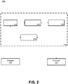
- FIG. 2 shows a simplified block diagram of a system 200 for reducing audio distortion resulting from a loss of audio data packets for signals transcoded to a lapped-transform domain signal, according to an embodiment, using the method 100 described in FIG. 1 .
- the exemplary system 200 includes an audio conferencing server 205 in communication with multiple endpoints 235 and 240.
- the audio conferencing server 205 may include communications transceiver 250, decoder 210, preprocessor 220, and encoder 230. While exemplary voice communication system 200 is shown as having a single server 205, the disclosure is not limited in this regard. In some examples, the voice communication system 200 may include a plurality of servers. For example, a first server may receive the packets of the audio stream and perform some processing (e.g., arranging the packets in sequence, when they are received out of order). A second server may perform decoding steps, and transmit the received raw audio signal and sideband information (e.g., received window sizes, the location of the missing packets in the sequence) to a third server, which may perform the pre-processing steps and encoding steps of method 100.
- a first server may receive the packets of the audio stream and perform some processing (e.g., arranging the packets in sequence, when they are received out of order).
- a second server may perform decoding steps, and transmit the received raw audio signal and sideband information (e.g.
- the method 100 may start at step 110, where the server of a voice-over internet protocol teleconference system 205 receives packets of an audio stream over a network connection from an endpoint 235 that transmits audio in a non-lapped transform domain format.
- the packets have a sequential order (e.g. a chronological order), where a block of packets that includes at least one packet is missing in the sequence.
- the packets are received in the sequential order, or, in an example not covered by the claimed invention, may be received out of order and may be reordered by the server prior to decoding.
- Each packet has a received window size, e.g., of a predetermined time duration (e.g., 20 ms); however, the received window size may change over time to a different time duration (i.e. the received window size of each packet of the audio stream may not be the same, due to the endpoint 235 choosing different window sizes for different kinds of audio signals, for example).
- the received packets may be in a first audio encoding format involving primarily a temporal block-based coding design, where time-domain samples are coded directly or in some compressed or predicted form in many cases (e.g., mobile devices, land-line signals, and the like).
- the packets have been encoded into a format suited for transmission, they are decoded into a raw audio signal so they are subsequently encoded into the lapped transform domain format.
- the server therefore decode the received packets from the non-lapped format to a raw audio signal at step 120.
- the decoding may be performed by the decoder 210, which receives the audio stream from the communications transceiver 250.
- the decoder 210 replaces each missing packet in the sequence at step 140.
- the missing packets may be replaced by blocks of silence; however, any suitable low-energy signal may be used to replace the missing packets.
- the decoder 210 may be modified from ordinary operation to remove any form or attempt of removing discontinuities in the event of packet loss. By deactivating any decoder-based loss concealment, the CPU load may be reduced for the server 205, since decoder-based loss concealment may generally be higher complexity than the packet loss concealment performed subsequently in method 100 (see below).
- the server 205 may then preprocess the decoded audio stream at step 150, by using the preprocessor 220, for example.
- the server 205 encodes the raw audio signal into transform windows having the lapped transform domain format at step 160 using encoder 230, which may also perform packet loss concealment in some examples. While the preprocessor 220 and the encoder 230 are shown as separate in server 205, some or all preprocessing steps may be executed by the encoder 230, which may be modified from a standard lapped transform domain format encoder to perform such steps. Preprocessing, conversion to the lapped transform domain, and the packet loss concealment are explained in greater detail in FIGs. 3 and 4 and the accompanying text below.
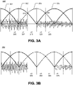
- FIGS. 3A-B show plots of sequences of blocks of a decoded raw audio stream that include missing packets and modifications of a reduced-energy signal block, according to various embodiments.
- the reduced-energy signal blocks of FIGS. 3A-B are shown as blocks of silence, any suitable substitute block having lower energy (to be clearly distinguishable from the received raw audio signal) are used to replace missing packets.
- x0 through x4 of plot 300 denote signal segments that have 1 ⁇ 4 the length of the transform window size (in the example, the segments have a duration of 10 ms).
- FIG. 4 shows a flow diagram for a method 400 of pre-processing and encoding a received raw audio stream, where the encoding includes packet loss concealment, according to an embodiment.
- steps 410 and 420 represent an embodiment of the preprocessing performed prior to encoding the raw audio stream into the lapped transform domain format (i.e. step 150 of method 100).
- steps 440 and 450 are embodiments of encoding the raw audio stream and performing packet loss concealment (e.g. at step 160 of method 100).
- the preprocessor 220 modifies each block of silence at one of a beginning boundary and an ending boundary at step 410 as part of the preprocessing to ease the transition between speech and silence.
- Segments x2 310 and x3 320 make up a single 20 ms block of silence bounded by beginning boundary 315 and ending boundary 330.
- a modified signal has been inserted at the ending boundary 330 of the inserted segment of silence x3 320.
- the modified signal may include a set of synthesized audio samples based on received raw audio samples from an adjacent block to the block of silence.
- segment x3 320 segment x4_reversed, the time-reversed version of the audio samples in the beginning of segment x4 325.
- the use of time-reversed copies of adjacent signal portions ties in with mathematical properties of the lapped transform domain to improve the smoothness of the transition between silence and signal playback.
- the length of that portion may be of any desired duration; the example of plot 300 shows a portion equal to 1 ⁇ 4 of the length of the transform window 335 that includes the end boundary of the block of silence (between segments x3 320 and x4 325).
- segment x2 310 may be replaced by a modified signal represented as g ⁇ (x0 - x1_reversed), where g is the gain or attenuation factor used in the later loss concealment step (derived from a shape of one or more window functions of the lapped transform domain format).
- g is the gain or attenuation factor used in the later loss concealment step (derived from a shape of one or more window functions of the lapped transform domain format).
- Replacing segment x2 310 with the expression g ⁇ (x0 - x1_reversed) may allow for a better preservation of the signal in x1_ (immediately before the silence), which may otherwise be slightly distorted in the later loss concealment step.
- the modification may include modifying the block of silence at both the beginning boundary and the ending boundary (e.g., by adding a reversed version of the audio signal in an adjacent block to the corresponding portions of the block of silence).
- the synthesizing audio samples may include one or more of dithering, decorrelating, and stochastic processing to reduce correlation and potential artifacts caused by the overlapping coding strategy of the lapped transform domain format.
- the preprocessor 220 shifts the raw audio signal by a predetermined delay such that a start and end of each block of missing packets does not coincide with a peak of a transform window of a lapped transform domain format.
- the audio signal may be represented as a series of blocks, where the signal in each block overlaps with part of the signal in the preceding and part of the signal in the following block. This may be seen in plot 300, where overlapping curves (e.g. curves 305 and 335) indicate the placement of transform windows (of 40 ms length, in the example) for conversion to the lapped transform domain. While in many examples the received window size is different from the transform window size, this is not necessarily always the case.
- the plot 350 in FIG. 3B shows a decoded raw audio signal having a received window size of 40 ms (stretching from segment x2 355 to segment x5 375), the same as the transform window size.
- the lapped transform domain format audio samples of the raw audio signal at the edge of a transform window are stored with a lower gain than those located at the center of a transform window. This is clearly shown in plot 300 by the height of the transform windows, which peaks at the center of the transform window.
- the goal of step 420 is to delay the raw audio signal such that the transitions between speech blocks and inserted silence blocks are not stored at maximum gain in any block.
- the transition points 315 and 330 have been shifted to not coincide with either of the centers of the transform windows 302 and 335 that include the transition points.
- the temporal alignment of the received raw audio signal may be shifted by 1 ⁇ 4 the transform window size.
- the transform windows surrounding an inserted silence are placed such that they either precede or follow the silence transition point by 1 ⁇ 4 of the transform window length.
- plot 300 demonstrates this principle; the transform window is 40 ms and the received window size of the audio signal is 20 ms, as the size of the transform window may frequently be different from the received window size.
- the received window size is an integer multiple of 1 ⁇ 2 the transform window size, e.g., if the transform window size is 40ms, the received window size is ideally 20, 40, 60ms etc.
- the received window is received at an optimal timing, no shift may be needed to align the received windows such that the start and the received windows do not coincide with the centers of the transform windows.
- a shift is commonly necessary to meet the condition that the start and end of the received windows do not coincide with the centers of the transform windows.
- the received window has a duration of 25ms and the transform window is 40ms
- the optimal alignment would be for the start boundary to be at 3 ⁇ 4 of the preceding "good” transform window, and the end boundary to be 1 ⁇ 4 into the next "good” transform window
- shifting may not be necessary for some lost packets (e.g., when the received window size is an integer multiple of 1 ⁇ 2 the transform window size, and the transform windows have been aligned optimally since the first received window in the received audio stream).
- the received window size may change over time (as previously noted), the transform window size may change over time, or the received audio stream may cease and resume whenever the remote participant stops and resumes speaking. Any of these cases may change the alignment between received and transform windows, and therefore require shifting the audio signal again to ensure optimal alignment.
- the server encodes the raw audio signal into transform windows having the lapped transform domain format at step 440.
- Packet loss concealment is performed for each transform window of the encoded audio signal that includes a modified reduced-energy signal block.
- transform windows that are centered over a reduced-energy signal block may not be encoded. Instead, these windows may be marked for loss concealment at step 440.
- the loss concealment step may, in some examples, be carried out after conversion of the signal to the lapped transform domain at step 450.
- the loss concealment may be implemented by replacing any previously marked window(s) (including selected window 305) with copies of the preceding windows, i.e., by repeating previous "good" windows.
- This is a loss concealment method with very low computational cost that exploits the soft overlap of transform windows in the lapped transform domain to provide smooth transitions between windows.
- method 400 shows loss concealment being performed by the server, prior to transmission, the disclosure is not limited in this regard. That is, in some examples not covered by the claimed invention, packet loss concealment may be performed by the endpoint after receiving the transmitted audio stream.
- a decoder of a receiving endpoint may, for example, receive the previously-marked windows and replace the marked windows with preceding windows. In this way, the packet loss may be partially propagated, and then some of the logic of packet loss looping or insertion of repeat MDCT frames happens at the other end.
- a first transform window of the block may be created using packet loss concealment by the server. For the remainder of the block of missing packets, the server may stop sending any encoded transform windows until a last window including the block of missing packets, where a fade-in (such as transform window 335) is applied.
- the endpoint receiver may function as a conventional decoder, and do the efficient low cost packet loss concealment on the received encoded audio stream.
- the first transform window of the block of missing packets may be omitted, as well as every other transform window including the block of missing packets, until the fade-in (e.g., transform window 335) is encoded and transmitted, again relying on the conventional packet loss concealment of the receiver of the endpoint to repeat the previous received transform windows.
- Performing packet loss concealment on the endpoint, rather than the server may advantageously further move computational load away from the server to the endpoints, allowing the server to process more audio streams simultaneously.
- one or more marked transform windows may be replaced by the immediately preceding window, i.e., window 305 is replaced by a copy of window 302 in plot 300. If the inserted silence spans multiple transform windows, the replacing transform window may be repeated multiple times (i.e., "302, 302, 302, ##).
- groups of two or more transform windows may be repeated as long as needed, i.e., "301, 302, 301, 302, 301, 302, "
- Repeating two or more transform windows may reduce potential artifacts that may occur with multiple repetitions of the same window, as the extended time between the looping of the transform windows may lead to a greater likelihood of decorrelated audio at the point of joining the looped transform windows. Having decorrelated audio may reduce the chances of constructive or destructive interference dominating the transition boundary between the last transform window of the looped sequence and the first transform window of the repeated group.
- transform windows may be repeated with a steadily decreasing gain e.g., eventually fading to silence for longer consecutive concealments.
- Another potential sequence for such blocks of missing packets may be a stochastic reverby fade away, expressed as: A B C D D ⁇ C ⁇ D ⁇ B ⁇ C ⁇ D ⁇ A ⁇ B ⁇ C ⁇ D ⁇ B ⁇ C ⁇ D ⁇ C ⁇ D ⁇ 0;
- the server 205 may transmit the encoded audio signal at step 170 to a recipient endpoint 240.
- the modified transform-domain signal may be transmitted by communications transceiver 250 to the recipient endpoint 240, where it may be decoded (i.e., converted to raw audio) for playback.
- Lapped transform domain decoders of the endpoint 240 may use the soft overlapping windows shown in Figure 3 to perform the inverse transform (i.e., decoding) to a raw audio signal.
- the soft overlap results in a smooth transition between original and concealed speech blocks, leading to high perceptual quality playback despite the packet loss from the initial transmission of the audio signal by endpoint 235.
- additional metadata may be included by the encoder 230 identifying presence of data that has been synthesized using packet loss concealment. This may facilitate downstream decisions regarding decoding, rendering, and/or use of retransmitted data to further reduce the perceptual impact of the discontinuity in some embodiments.
- While method 100 shows that the encoded audio signal is transmitted after being encoded.
- the encoded audio signal is stored on the server 205, for playback or transmission at a later time.
- server 205 may be a recording server for meeting minutes that can be accessed at a later time, or further processed on the server (e.g., automatic speech-to-text transcription).
- the steps of initially decoding incoming packets to PCM i.e., a raw digital audio signal in a time domain format
- PCM i.e., a raw digital audio signal in a time domain format
- the subsequent encoding to the target domain are generally treated as separate problems, and therefore optimized and achieved with different goals and constraints that may not reflect those of this system design, or take advantage of the particular nature of the decode and encode presented.
- the soft overlap used in the second step of encoding is used to help conceal any gaps in the received signal, and at the same time the highly lightweight and computationally efficient case of the first step of decoding the non-transform domain codec may be used for packet concealment.
- Packet loss concealment (“PLC”) extension, and onset prediction for a PCM signal can be accomplished via the use of predictive models such as LPC, ARMA, auto-regressive modeling and convolutional filtering.
- LPC Low-power Physical Coding
- ARMA ARMA
- convolutional filtering a PCM signal that can be accomplished via the use of predictive models such as LPC, ARMA, auto-regressive modeling and convolutional filtering.
- a first class of conventional time-domain decoders includes forms of PCM mapping (International Telecommunication Union speech coding standard G.711), simple ADPCM (e.g., speech coding standard G.722) or more complex linear predictive models like CELP and ACELP (e.g., speech coding standards G.729, G.722.2). While it is known that a transform-based softening of the PLC boundaries can be effective, this first class of conventional decoders are not transform domain-based, and significant computational complexity would be added by converting the time-domain decoders listed above just to take advantage of transform-based PLC. In the present disclosure however, the succession of the decode/encode process is designed as a system. Therefore, the cost of the transform is amortized or fixed in the encoder, and through this disclosure the transform-domain is effectively utilized to achieve a PLC on the decoded signal.
- PCM mapping International Telecommunication Union speech coding standard G.711
- simple ADPCM e.g., speech coding standard G.722
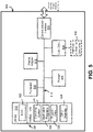
- FIG. 5 is a block diagram of an exemplary computing system for concealing packet loss in a multi-format voice communication system, according to various examples of the present disclosure.
- an exemplary system for implementing the subject matter disclosed herein, including the methods described above includes a hardware device 500, including a processing unit 502, memory 504, storage 506, data entry module 508, display adapter 510, communication interface 512, and a bus 514 that couples elements 504-512 to the processing unit 502.
- the bus 514 may comprise any type of bus architecture. Examples include a memory bus, a peripheral bus, a local bus, etc.
- the processing unit 502 is an instruction execution machine, apparatus, or device and may comprise a microprocessor, a digital signal processor, a graphics processing unit, an application specific integrated circuit (ASIC), a field programmable gate array (FPGA), etc.
- the processing unit 502 may be configured to execute program instructions stored in memory 504 and/or storage 506 and/or received via data entry module 508.
- the memory 504 may include read only memory (ROM) 516 and random access memory (RAM) 518.
- Memory 504 may be configured to store program instructions and data during operation of device 500.
- memory 504 may include any of a variety of memory technologies such as static random access memory (SRAM) or dynamic RAM (DRAM), including variants such as dual data rate synchronous DRAM (DDR SDRAM), error correcting code synchronous DRAM (ECC SDRAM), or RAMBUS DRAM (RDRAM), for example.
- SRAM static random access memory
- DRAM dynamic RAM
- DRAM dynamic RAM
- ECC SDRAM error correcting code synchronous DRAM
- RDRAM RAMBUS DRAM
- Memory 504 may also include nonvolatile memory technologies such as nonvolatile flash RAM (NVRAM) or ROM.
- NVRAM nonvolatile flash RAM
- NVRAM nonvolatile flash RAM
- ROM basic input/output system
- BIOS basic input/output system
- the storage 506 may include a flash memory data storage device for reading from and writing to flash memory, a hard disk drive for reading from and writing to a hard disk, a magnetic disk drive for reading from or writing to a removable magnetic disk, and/or an optical disk drive for reading from or writing to a removable optical disk such as a CD ROM, DVD or other optical media.
- the drives and their associated computer-readable media provide nonvolatile storage of computer readable instructions, data structures, program modules and other data for the hardware device 500.
- the methods described herein can be embodied in executable instructions stored in a non-transitory computer readable medium for use by or in connection with an instruction execution machine, apparatus, or device, such as a computer-based or processor-containing machine, apparatus, or device. It will be appreciated by those skilled in the art that for some examples, other types of computer readable media may be used which can store data that is accessible by a computer, such as magnetic cassettes, flash memory cards, digital video disks, Bernoulli cartridges, RAM, ROM, and the like may also be used in the exemplary operating environment.
- a "computer-readable medium” can include one or more of any suitable media for storing the executable instructions of a computer program in one or more of an electronic, magnetic, optical, and electromagnetic format, such that the instruction execution machine, system, apparatus, or device can read (or fetch) the instructions from the computer readable medium and execute the instructions for carrying out the described methods.
- a non-exhaustive list of conventional exemplary computer readable medium includes: a portable computer diskette; a RAM; a ROM; an erasable programmable read only memory (EPROM or flash memory); optical storage devices, including a portable compact disc (CD), a portable digital video disc (DVD), a high definition DVD (HD-DVD TM ), a BLU-RAY disc; and the like.
- a number of program modules may be stored on the storage 506, ROM 516 or RAM 518, including an operating system 522, one or more applications programs 524, program data 526, and other program modules 528.
- a user may enter commands and information into the hardware device 500 through data entry module 508.
- Data entry module 508 may include mechanisms such as a keyboard, a touch screen, a pointing device, etc.
- Other external input devices (not shown) are connected to the hardware device 500 via external data entry interface 530.
- external input devices may include a microphone, joystick, game pad, satellite dish, scanner, or the like.
- external input devices may include video or audio input devices such as a video camera, a still camera, etc.
- Data entry module 508 may be configured to receive input from one or more users of device 500 and to deliver such input to processing unit 502 and/or memory 504 via bus 514.
- the hardware device 500 may operate in a networked environment using logical connections to one or more remote nodes (not shown) via communication interface 512.
- the remote node may be another computer, a server, a router, a peer device or other common network node, and typically includes many or all of the elements described above relative to the hardware device 500.
- the communication interface 512 may interface with a wireless network and/or a wired network. Examples of wireless networks include, for example, a BLUETOOTH network, a wireless personal area network, a wireless 802.11 local area network (LAN), and/or wireless telephony network (e.g., a cellular, PCS, or GSM network).
- wireless networks include, for example, a BLUETOOTH network, a wireless personal area network, a wireless 802.11 local area network (LAN), and/or wireless telephony network (e.g., a cellular, PCS, or GSM network).
- wired networks include, for example, a LAN, a fiber optic network, a wired personal area network, a telephony network, and/or a wide area network (WAN).
- WAN wide area network
- communication interface 512 may include logic configured to support direct memory access (DMA) transfers between memory 504 and other devices.
- DMA direct memory access
- program modules depicted relative to the hardware device 500 may be stored in a remote storage device, such as, for example, on a server. It will be appreciated that other hardware and/or software to establish a communications link between the hardware device 500 and other devices may be used.
- At least one component defined by the claims is implemented at least partially as an electronic hardware component, such as an instruction execution machine (e.g., a processor-based or processor-containing machine) and/or as specialized circuits or circuitry (e.g., discrete logic gates interconnected to perform a specialized function), such as those illustrated in FIG. 5 .
- an instruction execution machine e.g., a processor-based or processor-containing machine
- specialized circuits or circuitry e.g., discrete logic gates interconnected to perform a specialized function
- the terms “component,” “module,” and “process,” may be used interchangeably to refer to a processing unit that performs a particular function and that may be implemented through computer program code (software), digital or analog circuitry, computer firmware, or any combination thereof.
Landscapes
- Engineering & Computer Science (AREA)
- Multimedia (AREA)
- Signal Processing (AREA)
- Physics & Mathematics (AREA)
- Audiology, Speech & Language Pathology (AREA)
- Health & Medical Sciences (AREA)
- Computational Linguistics (AREA)
- Human Computer Interaction (AREA)
- Acoustics & Sound (AREA)
- Computer Networks & Wireless Communication (AREA)
- Spectroscopy & Molecular Physics (AREA)
- Telephonic Communication Services (AREA)
- Compression, Expansion, Code Conversion, And Decoders (AREA)
Description
- Embodiments herein relate generally to audio signal processing, and more specifically to reducing audio distortion resulting from a loss of audio data packets in received signals that are transcoded to a lapped-transform domain signal using a low-complexity solution.
- The invention is defined by the independent claims. Embodiments are given by the dependent claims. Systems and methods are described for concealing packet loss in a received audio stream. A server of an audio, e.g., voice, communication system receives a sequence of packets of an audio stream, e.g., over a network connection. The received audio stream is in a non-lapped transform domain format, and the packets have a sequential order, where a block of packets is missing in the sequence. The block of packets includes at least one missing packet, and each packet has a received window size, e.g., of a predetermined time duration. The server decodes the received sequence of packets from the non-lapped format to a raw audio signal, and replaces each missing packet in the sequence with a reduced-energy signal block, such as a block of silence. The sequence of packets of the raw audio signals comprises at least one reduced-energy signal block, wherein the at least one reduced-energy signal block has a lower energy in comparison to every other packets of the raw audio signal, such that the reduced-energy signal block is distinguishable from every other packets of the raw audio signal. The server also modifies each reduced-energy signal block at a beginning boundary and/or an ending boundary of the reduced-energy signal block, and shifts the raw audio signal, based on the received window size, by a predetermined delay such that the beginning boundary and the ending boundary of each reduced-energy signal block of the raw audio signal does not coincide with a peak of a transform window of a lapped transform domain format.
- After the shifting, the server encodes the shifted raw audio signal into an encoded audio signal having transform windows having the lapped transform domain format. Packet loss concealment is performed for each transform window of the encoded audio signal that includes a modified reduced-energy signal block. After the encoding, the server subsequently transmits the encoded audio signal to an endpoint. The packet loss concealment is performed by the server prior to transmitting the encoded audio signal.
-
US 2016/0148618 A1 discloses a packet loss concealment apparatus and method, and audio processing system. According to an embodiment, the packet loss concealment apparatus is provided for concealing packet losses in a stream of audio packets, each audio packet comprising at least one audio frame in transmission format comprising at least one monaural component and at least one spatial component. The packet loss concealment apparatus may comprise a first concealment unit for creating the at least one monaural component for a lost frame in a lost packet and a second concealment unit for creating the at least one spatial component for the lost frame. According to the embodiment, spatial artifacts such as incorrect angle and diffuseness may be avoided as far as possible in PLC for multi-channel spatial or sound field encoded audio signals. -
US2011/0022924 A1 discloses a device and a method for resynchronization and recovery after frame erasure concealment of an encoded sound signal comprise decoding, in a current frame, a correctly received signal after the frame erasure. Frame erasure concealment is extended in the current frame using an erasure-concealed signal from a previous frame to produce an extended erasure concealed signal. The extended erasure-concealed signal is correlated with the decoded signal in the current frame and the extended erasure-concealed signal is synchronized with the decoded signal in response to the correlation. A smooth transition is produced in the current frame from the synchronized extended erasure-concealed signal to the decoded signal. - This disclosure is illustrated by way of example and not limitation in the figures of the accompanying drawings, in which like references indicate similar elements, and in which:
-
FIG. 1 shows a flow diagram for a method for reducing audio distortion resulting from a loss of audio data packets for signals transcoded to a lapped-transform domain signal, according to an embodiment. -
FIG. 2 shows a simplified block diagram of a system for reducing audio distortion resulting from a loss of audio data packets for signals transcoded to a lapped-transform domain signal, according to an embodiment. -
FIGS. 3A-B show plots of sequences of blocks of a decoded raw audio stream that include missing packets and modifications of a reduced-energy signal block, according to various embodiments. -
FIG. 4 shows a flow diagram for a method of pre-processing and encoding a received raw audio stream, where the encoding includes packet loss concealment, according to an example. -
FIG. 5 is a block diagram of an exemplary system for reducing audio distortion resulting from a loss of audio data packets for signals transcoded to a lapped-transform domain signal, according to an example. - Voice over IP (VoIP)-based communication systems, like Dolby Voice (developed by Dolby Laboratories, Inc. of California, United States of America), generally transmit audio signals as a series of packets. Each packet contains a small portion of the audio signal (typically 20 milliseconds). A common issue in VoIP-based systems is that some packets do not reach their destination on time or even at all (e.g. due to poor network connection between a meeting participant and the back-end conferencing system server). This results in gaps or blanks in the received audio signal that may sound highly annoying to a listener. Loss concealment may be defined as a signal processing step to reduce the perceived distortion caused by losses/errors/interruptions during transmission. To fill the blanks caused by lost packets, packet loss concealment may be used to replace lost packets with a made-up signal to make them less conspicuous to the listener. The made-up signal is usually computed such as to sound similar to the received speech packets immediately preceding the lost packets, with a smooth transition added.
- Some audio conferencing systems (such as Dolby Voice) may use a signal representation known as the lapped transform domain that allows for packet loss concealment at a very low computational cost. The lapped transform domain (also known as the soft overlap transform domain) format may be a type of audio format that stores the signal in a sequence of short blocks with frequency-domain information, where each block overlaps with part of the previous and part of the following block's signal. Lapped transforms are often used where there may be changes to signal switching, routing, delay and mixing. The soft overlap of blocks provides a cross fade or somewhat smoothed boundary between blocks, even should any packet go missing or be interchanged in streaming and rendering. Lapped transforms are also commonly deployed in audio coding where each windowed frame of audio is suitable for analysis and coding in some frequency domain representation. This type of format is used in Dolby Voice, MP3, or AC4, for example. Audio conferencing systems that use a lapped transform domain format may allow participants to connect both using the endpoints that transmit signals in a lapped transform domain format, as well as through landline, cellular or other types of connections that transmit signals in other formats (e.g., non-overlapping time blocks). The server of the audio conferencing system transforms speech signals that are received from the latter, non-lapped endpoints to the lapped transform domain format. Non-lapped transform domain endpoints of a voice communications system may use formats that require more computationally-expensive methods for loss concealment, generally performed by the audio conferencing system upon receiving an audio signal from the endpoint. The conventional solution to packet loss when a non-lapped transform domain signal is received is to decode the received data to a raw audio signal, perform loss concealment as part of the decoding process or as an additional step, and then convert the resulting signal to the desired signal format (e.g., Dolby Voice), i.e., to perform loss concealment and format conversion in two separate steps.
- The present disclosure seeks to maintain the low computational cost advantage of using a lapped transform domain signal format for non-lapped transform domain formatted audio signals received from endpoints connecting over a network to the audio conferencing system. It uses a modified signal flow where each lost packet is replaced (by silence or another low-energy signal) and marked for later concealment. The received signal may be preprocessed such that the beginnings and ends of lost packet blocks line up in a specific way with the positions of lapped transform domain windows. This preprocessing step may help avoid audible distortions at the transitions between speech and lost packets. The preprocessed signal is then transformed to the soft overlap transform domain, where the lost packets can be concealed through low-complexity techniques that exploit the soft overlap and other mathematical properties of the lapped transform domain. Silence insertion alone may create abrupt transitions between the audio signal and lost packets in the signal. This results in clicks or "pops" that may remain audible even after the loss concealment step. The preprocessing step before the conversion step may help to avoid this.
- Once the signal is represented in the lapped transform format, the previously marked transform windows in it can be concealed at a lower computational cost. The combination of all steps provides a complete system for low-complexity, yet high quality packet loss concealment and audio format conversion. The method is designed to minimize the complexity of computations performed at the server. Low complexity is a key requirement to provide the efficiency and associated high scalability of the Dolby Voice server. The disclosed solution stands above conventional solutions in that it does not treat loss concealment as a separate process, but rather combines it with the audio format conversion step to yield a complete system that offers both high quality and low complexity.
- A method for improving the end-to-end transport of low-latency audio signals over a potentially lossy network is described herein.
FIG. 1 shows a flow diagram for amethod 100 for reducing audio distortion resulting from a loss of audio data packets for signals transcoded to a lapped-transform domain signal, according to an embodiment.FIG. 2 shows a simplified block diagram of asystem 200 for reducing audio distortion resulting from a loss of audio data packets for signals transcoded to a lapped-transform domain signal, according to an embodiment, using themethod 100 described inFIG. 1 . Theexemplary system 200 includes anaudio conferencing server 205 in communication withmultiple endpoints audio conferencing server 205 may includecommunications transceiver 250,decoder 210,preprocessor 220, andencoder 230. While exemplaryvoice communication system 200 is shown as having asingle server 205, the disclosure is not limited in this regard. In some examples, thevoice communication system 200 may include a plurality of servers. For example, a first server may receive the packets of the audio stream and perform some processing (e.g., arranging the packets in sequence, when they are received out of order). A second server may perform decoding steps, and transmit the received raw audio signal and sideband information (e.g., received window sizes, the location of the missing packets in the sequence) to a third server, which may perform the pre-processing steps and encoding steps ofmethod 100. - The
method 100 may start atstep 110, where the server of a voice-over internetprotocol teleconference system 205 receives packets of an audio stream over a network connection from anendpoint 235 that transmits audio in a non-lapped transform domain format. The packets have a sequential order (e.g. a chronological order), where a block of packets that includes at least one packet is missing in the sequence. The packets are received in the sequential order, or, in an example not covered by the claimed invention, may be received out of order and may be reordered by the server prior to decoding. Each packet has a received window size, e.g., of a predetermined time duration (e.g., 20 ms); however, the received window size may change over time to a different time duration (i.e. the received window size of each packet of the audio stream may not be the same, due to theendpoint 235 choosing different window sizes for different kinds of audio signals, for example). The received packets may be in a first audio encoding format involving primarily a temporal block-based coding design, where time-domain samples are coded directly or in some compressed or predicted form in many cases (e.g., mobile devices, land-line signals, and the like). - Because the packets have been encoded into a format suited for transmission, they are decoded into a raw audio signal so they are subsequently encoded into the lapped transform domain format. The server therefore decode the received packets from the non-lapped format to a raw audio signal at
step 120. The decoding may be performed by thedecoder 210, which receives the audio stream from thecommunications transceiver 250. In addition to decoding the received audio packets, thedecoder 210 replaces each missing packet in the sequence atstep 140. In an example, the missing packets may be replaced by blocks of silence; however, any suitable low-energy signal may be used to replace the missing packets. In some examples, thedecoder 210 may be modified from ordinary operation to remove any form or attempt of removing discontinuities in the event of packet loss. By deactivating any decoder-based loss concealment, the CPU load may be reduced for theserver 205, since decoder-based loss concealment may generally be higher complexity than the packet loss concealment performed subsequently in method 100 (see below). - The
server 205 may then preprocess the decoded audio stream atstep 150, by using thepreprocessor 220, for example. After the preprocessing, theserver 205 encodes the raw audio signal into transform windows having the lapped transform domain format atstep 160 usingencoder 230, which may also perform packet loss concealment in some examples. While thepreprocessor 220 and theencoder 230 are shown as separate inserver 205, some or all preprocessing steps may be executed by theencoder 230, which may be modified from a standard lapped transform domain format encoder to perform such steps. Preprocessing, conversion to the lapped transform domain, and the packet loss concealment are explained in greater detail inFIGs. 3 and4 and the accompanying text below. -
FIGS. 3A-B show plots of sequences of blocks of a decoded raw audio stream that include missing packets and modifications of a reduced-energy signal block, according to various embodiments. Again, while the reduced-energy signal blocks ofFIGS. 3A-B are shown as blocks of silence, any suitable substitute block having lower energy (to be clearly distinguishable from the received raw audio signal) are used to replace missing packets. FromFIG. 3A , x0 through x4 ofplot 300 denote signal segments that have ¼ the length of the transform window size (in the example, the segments have a duration of 10 ms). Plot 300 shows a single lost packet (having a window size of 20 ms, in the example, which equals two segments in plot 300) replaced by a block of silence (atx2 310 and x3 320), although the same steps can be applied to consecutive lost packets as well.FIG. 4 shows a flow diagram for amethod 400 of pre-processing and encoding a received raw audio stream, where the encoding includes packet loss concealment, according to an embodiment. Inmethod 400,steps step 150 of method 100).Steps step 160 of method 100). - The
preprocessor 220 modifies each block of silence at one of a beginning boundary and an ending boundary atstep 410 as part of the preprocessing to ease the transition between speech and silence.Segments x2 310 andx3 320 make up a single 20 ms block of silence bounded by beginningboundary 315 and endingboundary 330. As shown inFIG. 3A , a modified signal has been inserted at the endingboundary 330 of the inserted segment ofsilence x3 320. The modified signal may include a set of synthesized audio samples based on received raw audio samples from an adjacent block to the block of silence. - The synthesized audio samples may be derived using several different techniques. As done in the example shown in
plot 300, the last portion of each inserted silence may be replaced by a time-reversed copy of the signal following immediately after the silence (i.e.,segment x3 320 = segment x4_reversed, the time-reversed version of the audio samples in the beginning of segment x4 325). In general, the use of time-reversed copies of adjacent signal portions ties in with mathematical properties of the lapped transform domain to improve the smoothness of the transition between silence and signal playback. The length of that portion may be of any desired duration; the example ofplot 300 shows a portion equal to ¼ of the length of thetransform window 335 that includes the end boundary of the block of silence (betweensegments x3 320 and x4 325). An alternative example ofstep 410 may be to replace the first portion of each inserted silence by a time-reversed copy of the signal immediately preceding the silence (i.e., replacingx2 310 = x1_reversed, a time-reversed copy of the raw audio signal in segment x1 307). In yet another alternative example, a portion ofsegment x2 310 may be replaced by a modified signal represented as g∗(x0 - x1_reversed), where g is the gain or attenuation factor used in the later loss concealment step (derived from a shape of one or more window functions of the lapped transform domain format). Replacingsegment x2 310 with the expression g∗(x0 - x1_reversed) may allow for a better preservation of the signal in x1_ (immediately before the silence), which may otherwise be slightly distorted in the later loss concealment step. In yet another example, the modification may include modifying the block of silence at both the beginning boundary and the ending boundary (e.g., by adding a reversed version of the audio signal in an adjacent block to the corresponding portions of the block of silence). Finally, the synthesizing audio samples may include one or more of dithering, decorrelating, and stochastic processing to reduce correlation and potential artifacts caused by the overlapping coding strategy of the lapped transform domain format. - At
step 420, thepreprocessor 220 shifts the raw audio signal by a predetermined delay such that a start and end of each block of missing packets does not coincide with a peak of a transform window of a lapped transform domain format. In the lapped transform domain, the audio signal may be represented as a series of blocks, where the signal in each block overlaps with part of the signal in the preceding and part of the signal in the following block. This may be seen inplot 300, where overlapping curves (e.g. curves 305 and 335) indicate the placement of transform windows (of 40 ms length, in the example) for conversion to the lapped transform domain. While in many examples the received window size is different from the transform window size, this is not necessarily always the case. Theplot 350 inFIG. 3B shows a decoded raw audio signal having a received window size of 40 ms (stretching fromsegment x2 355 to segment x5 375), the same as the transform window size. - In the lapped transform domain format, audio samples of the raw audio signal at the edge of a transform window are stored with a lower gain than those located at the center of a transform window. This is clearly shown in
plot 300 by the height of the transform windows, which peaks at the center of the transform window. The goal ofstep 420 is to delay the raw audio signal such that the transitions between speech blocks and inserted silence blocks are not stored at maximum gain in any block. Inplot 300, thetransition points transform windows transform windows - There can be special cases depending on the combination of received window size and transform window size. Ideally, the received window size is an integer multiple of ½ the transform window size, e.g., if the transform window size is 40ms, the received window size is ideally 20, 40, 60ms etc. In some cases, if the received window is received at an optimal timing, no shift may be needed to align the received windows such that the start and the received windows do not coincide with the centers of the transform windows. However, even when the received window is the same size as the transform window, a shift is commonly necessary to meet the condition that the start and end of the received windows do not coincide with the centers of the transform windows. However, if, for example, the received window has a duration of 25ms and the transform window is 40ms, then there is no shifting that will optimally align both the start AND the end boundary of missing received packets (the optimal alignment would be for the start boundary to be at ¾ of the preceding "good" transform window, and the end boundary to be ¼ into the next "good" transform window), so a sub-optimal shift is selected that ensures that the start and end of the block of missing packets does not coincide with a peak of a transform window. Also, shifting may not be necessary for some lost packets (e.g., when the received window size is an integer multiple of ½ the transform window size, and the transform windows have been aligned optimally since the first received window in the received audio stream). However, in some cases the received window size may change over time (as previously noted), the transform window size may change over time, or the received audio stream may cease and resume whenever the remote participant stops and resumes speaking. Any of these cases may change the alignment between received and transform windows, and therefore require shifting the audio signal again to ensure optimal alignment.
- After the shifting, the server encodes the raw audio signal into transform windows having the lapped transform domain format at
step 440. Packet loss concealment is performed for each transform window of the encoded audio signal that includes a modified reduced-energy signal block. To do so, in an example, transform windows that are centered over a reduced-energy signal block (e.g.,window 305, which includes a block of silence) may not be encoded. Instead, these windows may be marked for loss concealment atstep 440. - The loss concealment step may, in some examples, be carried out after conversion of the signal to the lapped transform domain at
step 450. The loss concealment may be implemented by replacing any previously marked window(s) (including selected window 305) with copies of the preceding windows, i.e., by repeating previous "good" windows. This is a loss concealment method with very low computational cost that exploits the soft overlap of transform windows in the lapped transform domain to provide smooth transitions between windows. Whilemethod 400 shows loss concealment being performed by the server, prior to transmission, the disclosure is not limited in this regard. That is, in some examples not covered by the claimed invention, packet loss concealment may be performed by the endpoint after receiving the transmitted audio stream. A decoder of a receiving endpoint may, for example, receive the previously-marked windows and replace the marked windows with preceding windows. In this way, the packet loss may be partially propagated, and then some of the logic of packet loss looping or insertion of repeat MDCT frames happens at the other end. In some examples, where the block of packets includes multiple lost packets, a first transform window of the block (window 305 inFigure 3A ) may be created using packet loss concealment by the server. For the remainder of the block of missing packets, the server may stop sending any encoded transform windows until a last window including the block of missing packets, where a fade-in (such as transform window 335) is applied. If the flag or sequence number then at a receiver of the receiving endpoint sees the omitted transform windows from the encoded audio stream (from the server) as packet loss, the endpoint receiver may function as a conventional decoder, and do the efficient low cost packet loss concealment on the received encoded audio stream. In some embodiments, even the first transform window of the block of missing packets may be omitted, as well as every other transform window including the block of missing packets, until the fade-in (e.g., transform window 335) is encoded and transmitted, again relying on the conventional packet loss concealment of the receiver of the endpoint to repeat the previous received transform windows. Performing packet loss concealment on the endpoint, rather than the server, may advantageously further move computational load away from the server to the endpoints, allowing the server to process more audio streams simultaneously. - When multiple consecutive transform windows are replaced using loss concealment, several different approaches may be used. For example, one or more marked transform windows may be replaced by the immediately preceding window, i.e.,
window 305 is replaced by a copy ofwindow 302 inplot 300. If the inserted silence spans multiple transform windows, the replacing transform window may be repeated multiple times (i.e., "302, 302, 302, ..."). In an alternative example for longer consecutive concealments, groups of two or more transform windows may be repeated as long as needed, i.e., "301, 302, 301, 302, 301, 302, ..." Repeating two or more transform windows may reduce potential artifacts that may occur with multiple repetitions of the same window, as the extended time between the looping of the transform windows may lead to a greater likelihood of decorrelated audio at the point of joining the looped transform windows. Having decorrelated audio may reduce the chances of constructive or destructive interference dominating the transition boundary between the last transform window of the looped sequence and the first transform window of the repeated group. Also, in an exemplary embodiment, transform windows may be repeated with a steadily decreasing gain e.g., eventually fading to silence for longer consecutive concealments. - Other approaches may be used to replace the missing transform windows when the block of missing packets affects multiple transform windows in an encoded stream, based on the idea that decorrelation at transitions between repeat windows and received signal windows is preferable. For example, suppose four transform windows prior to the block of missing packets are labeled "A, B, C, D," and A' indicates a time-reversed copy of transform window A. A possible sequence for a longer block of missing packets may be indicated as "AB C D C' B' A' C' B' A," where the loop runs backwards. Sequences like this (or similar sequences such as "A BCD D C D BCD... ") may be advantageous to account for blocks of missing packets having an unknown or indefinite length. Another potential sequence for such blocks of missing packets may be a stochastic reverby fade away, expressed as:
A B C D D∗ C∗ D∗∗ B∗∗ C∗∗∗ D∗∗∗ A∗∗∗∗ B∗∗∗∗ C∗∗∗∗ D∗∗∗∗∗ B∗∗∗∗∗∗ C∗∗∗∗∗∗ D∗∗∗∗∗∗ C∗∗∗∗∗∗∗ D∗∗∗∗∗∗∗ 0; - Where the "∗" represent a decorrelated version of a previous indicated transform window that also has a 2dB decay.
- Returning to
FIGs. 1 and2 , after packet loss concealment has been performed, theserver 205 may transmit the encoded audio signal atstep 170 to arecipient endpoint 240. The modified transform-domain signal may be transmitted bycommunications transceiver 250 to therecipient endpoint 240, where it may be decoded (i.e., converted to raw audio) for playback. Lapped transform domain decoders of theendpoint 240 may use the soft overlapping windows shown inFigure 3 to perform the inverse transform (i.e., decoding) to a raw audio signal. The soft overlap results in a smooth transition between original and concealed speech blocks, leading to high perceptual quality playback despite the packet loss from the initial transmission of the audio signal byendpoint 235. In an exemplary embodiment, additional metadata may be included by theencoder 230 identifying presence of data that has been synthesized using packet loss concealment. This may facilitate downstream decisions regarding decoding, rendering, and/or use of retransmitted data to further reduce the perceptual impact of the discontinuity in some embodiments. - While
method 100 shows that the encoded audio signal is transmitted after being encoded. In some examples not covered by the claimed invention, after packet loss concealment has been performed, the encoded audio signal is stored on theserver 205, for playback or transmission at a later time. For example,server 205 may be a recording server for meeting minutes that can be accessed at a later time, or further processed on the server (e.g., automatic speech-to-text transcription). - In conventional solutions to the problem of dealing with packet loss for non-lapped transform domain-formatted audio, the steps of initially decoding incoming packets to PCM (i.e., a raw digital audio signal in a time domain format) and the subsequent encoding to the target domain are generally treated as separate problems, and therefore optimized and achieved with different goals and constraints that may not reflect those of this system design, or take advantage of the particular nature of the decode and encode presented. Notably, as described above the soft overlap used in the second step of encoding is used to help conceal any gaps in the received signal, and at the same time the highly lightweight and computationally efficient case of the first step of decoding the non-transform domain codec may be used for packet concealment.
- Conventional packet loss solutions teach the compartmentalization of these two processes - the decode and encode - which when combined together in the best known prior art are computationally expensive and can create a worse perceptual result than the present disclosure. The following lists some known prior art for the compartmentalized packet loss concealment of the initial decode, and briefly details the deficiencies and suboptimality issues of that approach.
- Packet loss concealment ("PLC") extension, and onset prediction for a PCM signal can be accomplished via the use of predictive models such as LPC, ARMA, auto-regressive modeling and convolutional filtering. The analysis stages of these approaches are very computationally expensive and tend to suffer from the following challenges: they are only useful for short sections of loss, generally less than the size (> 20 ms) of losses in the audio conferencing context, when extended these approaches can sound very melodic, as spurious short tones can be extended well beyond their natural length, and such approaches are numerically posed, but often perceptually challenged for creating the onset softening samples, and a transform based reversal is often superior.
- A first class of conventional time-domain decoders includes forms of PCM mapping (International Telecommunication Union speech coding standard G.711), simple ADPCM (e.g., speech coding standard G.722) or more complex linear predictive models like CELP and ACELP (e.g., speech coding standards G.729, G.722.2). While it is known that a transform-based softening of the PLC boundaries can be effective, this first class of conventional decoders are not transform domain-based, and significant computational complexity would be added by converting the time-domain decoders listed above just to take advantage of transform-based PLC. In the present disclosure however, the succession of the decode/encode process is designed as a system. Therefore, the cost of the transform is amortized or fixed in the encoder, and through this disclosure the transform-domain is effectively utilized to achieve a PLC on the decoded signal.
- Due to the combined design, and to achieve the efficiency goal, the intermediate PLC'd PCM signal is never actually present in the combined decode / encode process. This is a clear indication of the joint design and optimization and sets it apart from any prior art, where the goal and design would be to clearly construct a PLC'd version of the signal prior to encoding. The fully gap-concealed version of the signal is not present until the final decode of the transform-based codec in use - in effect the computational complexity of the packet loss concealment is shifted from occurring in the input decode, to being spread across the encode and final decode of the audio. This is of significant advantage where, as described, the transcoding or combined decode/encode process is occurring on a central processing resource (i.e., the Dolby Voice server).
- Since the intermediate PLC'd PCM signal is not created, it does not make sense in the present approach to individually test the performance of the decoder and encoder. It is taught in prior art often that the best result comes from ensuring high performance of the individual codecs - encode to decode of the PCM-style codec and PLC, and encode to decode of the second transform-based codec and PLC. This is not possible with the present work, rather we seek to implement and test PLC across the entire system, which will include two audio codecs and two potential locations of packet loss. As presented though, the optimization of the concatenated and full dual codec transport can achieve the required perceptual performance and better computational complexity. Testing and optimizing the performance of the separate codecs, when they will always be concatenated, is neither necessary nor sufficient to achieve the globally optimized solution.
- While the solutions described herein for concealing packet loss are in the context of audio streams and a voice communications system, other examples are contemplated. Any context where transcoding is used for received data streams may utilize the systems and methods described herein to efficiently conceal packet loss over a network connection.
- The methods and modules described above may be implemented using hardware or software running on a computing system.
FIG. 5 is a block diagram of an exemplary computing system for concealing packet loss in a multi-format voice communication system, according to various examples of the present disclosure. With reference toFIG. 5 , an exemplary system for implementing the subject matter disclosed herein, including the methods described above, includes ahardware device 500, including aprocessing unit 502,memory 504,storage 506,data entry module 508,display adapter 510,communication interface 512, and abus 514 that couples elements 504-512 to theprocessing unit 502. - The
bus 514 may comprise any type of bus architecture. Examples include a memory bus, a peripheral bus, a local bus, etc. Theprocessing unit 502 is an instruction execution machine, apparatus, or device and may comprise a microprocessor, a digital signal processor, a graphics processing unit, an application specific integrated circuit (ASIC), a field programmable gate array (FPGA), etc. Theprocessing unit 502 may be configured to execute program instructions stored inmemory 504 and/orstorage 506 and/or received viadata entry module 508. - The
memory 504 may include read only memory (ROM) 516 and random access memory (RAM) 518.Memory 504 may be configured to store program instructions and data during operation ofdevice 500. In various examples,memory 504 may include any of a variety of memory technologies such as static random access memory (SRAM) or dynamic RAM (DRAM), including variants such as dual data rate synchronous DRAM (DDR SDRAM), error correcting code synchronous DRAM (ECC SDRAM), or RAMBUS DRAM (RDRAM), for example.Memory 504 may also include nonvolatile memory technologies such as nonvolatile flash RAM (NVRAM) or ROM. In some examples, it is contemplated thatmemory 504 may include a combination of technologies such as the foregoing, as well as other technologies not specifically mentioned. When the subject matter is implemented in a computer system, a basic input/output system (BIOS) 520, containing the basic routines that help to transfer information between elements within the computer system, such as during start-up, is stored inROM 516. - The
storage 506 may include a flash memory data storage device for reading from and writing to flash memory, a hard disk drive for reading from and writing to a hard disk, a magnetic disk drive for reading from or writing to a removable magnetic disk, and/or an optical disk drive for reading from or writing to a removable optical disk such as a CD ROM, DVD or other optical media. The drives and their associated computer-readable media provide nonvolatile storage of computer readable instructions, data structures, program modules and other data for thehardware device 500. - It is noted that the methods described herein can be embodied in executable instructions stored in a non-transitory computer readable medium for use by or in connection with an instruction execution machine, apparatus, or device, such as a computer-based or processor-containing machine, apparatus, or device. It will be appreciated by those skilled in the art that for some examples, other types of computer readable media may be used which can store data that is accessible by a computer, such as magnetic cassettes, flash memory cards, digital video disks, Bernoulli cartridges, RAM, ROM, and the like may also be used in the exemplary operating environment. As used here, a "computer-readable medium" can include one or more of any suitable media for storing the executable instructions of a computer program in one or more of an electronic, magnetic, optical, and electromagnetic format, such that the instruction execution machine, system, apparatus, or device can read (or fetch) the instructions from the computer readable medium and execute the instructions for carrying out the described methods. A non-exhaustive list of conventional exemplary computer readable medium includes: a portable computer diskette; a RAM; a ROM; an erasable programmable read only memory (EPROM or flash memory); optical storage devices, including a portable compact disc (CD), a portable digital video disc (DVD), a high definition DVD (HD-DVD™), a BLU-RAY disc; and the like.
- A number of program modules may be stored on the
storage 506,ROM 516 orRAM 518, including anoperating system 522, one ormore applications programs 524,program data 526, andother program modules 528. A user may enter commands and information into thehardware device 500 throughdata entry module 508.Data entry module 508 may include mechanisms such as a keyboard, a touch screen, a pointing device, etc. Other external input devices (not shown) are connected to thehardware device 500 via externaldata entry interface 530. By way of example and not limitation, external input devices may include a microphone, joystick, game pad, satellite dish, scanner, or the like. In some examples, external input devices may include video or audio input devices such as a video camera, a still camera, etc.Data entry module 508 may be configured to receive input from one or more users ofdevice 500 and to deliver such input toprocessing unit 502 and/ormemory 504 viabus 514. - The
hardware device 500 may operate in a networked environment using logical connections to one or more remote nodes (not shown) viacommunication interface 512. The remote node may be another computer, a server, a router, a peer device or other common network node, and typically includes many or all of the elements described above relative to thehardware device 500. Thecommunication interface 512 may interface with a wireless network and/or a wired network. Examples of wireless networks include, for example, a BLUETOOTH network, a wireless personal area network, a wireless 802.11 local area network (LAN), and/or wireless telephony network (e.g., a cellular, PCS, or GSM network). Examples of wired networks include, for example, a LAN, a fiber optic network, a wired personal area network, a telephony network, and/or a wide area network (WAN). Such networking environments are commonplace in intranets, the Internet, offices, enterprise-wide computer networks and the like. In some examples,communication interface 512 may include logic configured to support direct memory access (DMA) transfers betweenmemory 504 and other devices. - In a networked environment, program modules depicted relative to the
hardware device 500, or portions thereof, may be stored in a remote storage device, such as, for example, on a server. It will be appreciated that other hardware and/or software to establish a communications link between thehardware device 500 and other devices may be used. - It should be understood that the arrangement of
hardware device 500 illustrated inFIG. 5 is but one possible implementation and that other arrangements are possible. It should also be understood that the various system components (and means) defined by the claims, described above, and illustrated in the various block diagrams represent logical components that are configured to perform the functionality described herein. For example, one or more of these system components (and means) can be realized, in whole or in part, by at least some of the components illustrated in the arrangement ofhardware device 500. In addition, while at least one of these components are implemented at least partially as an electronic hardware component, and therefore constitutes a machine, the other components may be implemented in software, hardware, or a combination of software and hardware. More particularly, at least one component defined by the claims is implemented at least partially as an electronic hardware component, such as an instruction execution machine (e.g., a processor-based or processor-containing machine) and/or as specialized circuits or circuitry (e.g., discrete logic gates interconnected to perform a specialized function), such as those illustrated inFIG. 5 . Other components may be implemented in software, hardware, or a combination of software and hardware. Moreover, some or all of these other components may be combined, some may be omitted altogether, and additional components can be added while still achieving the functionality described herein. - In the description above, the subject matter may be described with reference to acts and symbolic representations of operations that are performed by one or more devices, unless indicated otherwise. As such, it will be understood that such acts and operations, which are at times referred to as being computer-executed, include the manipulation by the processing unit of data in a structured form. This manipulation transforms the data or maintains it at locations in the memory system of the computer, which reconfigures or otherwise alters the operation of the device in a manner well understood by those skilled in the art. The data structures where data is maintained are physical locations of the memory that have particular properties defined by the format of the data. However, while the subject matter is being described in the foregoing context, it is not meant to be limiting as those of skill in the art will appreciate that various of the acts and operation described hereinafter may also be implemented in hardware.
- For purposes of the present description, the terms "component," "module," and "process," may be used interchangeably to refer to a processing unit that performs a particular function and that may be implemented through computer program code (software), digital or analog circuitry, computer firmware, or any combination thereof.
- It should be noted that the various functions disclosed herein may be described using any number of combinations of hardware, firmware, and/or as data and/or instructions embodied in various machine-readable or computer-readable media, in terms of their behavioral, register transfer, logic component, and/or other characteristics. Computer-readable media in which such formatted data and/or instructions may be embodied include, but are not limited to, physical (non-transitory), non-volatile storage media in various forms, such as optical, magnetic or semiconductor storage media.
- Unless the context clearly requires otherwise, throughout the description and the claims, the words "comprise," "comprising," and the like are to be construed in an inclusive sense as opposed to an exclusive or exhaustive sense; that is to say, in a sense of "including, but not limited to." Words using the singular or plural number also include the plural or singular number respectively. Additionally, the words "herein," "hereunder," "above," "below," and words of similar import refer to this application as a whole and not to any particular portions of this application. When the word "or" is used in reference to a list of two or more items, that word covers all of the following interpretations of the word: any of the items in the list, all of the items in the list and any combination of the items in the list.
- In the description above and throughout, numerous specific details are set forth in order to provide a thorough understanding of the disclosure. It will be evident, however, to one of ordinary skill in the art, that the disclosure may be practiced without these specific details. In other instances, well-known structures and devices are shown in block diagram form to facilitate explanation. The description is not intended to limit the scope of the claims appended hereto. Further, in the methods disclosed herein, various steps are disclosed illustrating some of the functions of the disclosure. One will appreciate that these steps are merely exemplary and are not meant to be limiting in any way. Other steps and functions may be contemplated without departing from this disclosure.
Claims (10)
- A method for concealing packet loss in a received audio stream, the method comprising:receiving, by an audio communication system comprising one or more servers, a sequence of packets of an audio stream in a non-lapped transform domain format, the packets having a sequential order, wherein at least one packet is missing in the sequence, each packet of the audio stream having a received window size;decoding, by the audio communication system, the sequence of packets of the received audio stream from the non-lapped transform domain format to a sequence of packets of a raw audio signal;replacing, by the audio communication system, each packet of the raw audio signal missing in the sequence of packets of the raw audio signal with a reduced-energy signal block, whereby the sequence of packets of the raw audio signal comprises at least one reduced-energy signal block, wherein the at least one reduced-energy signal block has a lower energy in comparison to every other packets of the raw audio signal, such that the reduced-energy signal block is distinguishable from every other packets of the raw audio signal;modifying, by the audio communication system, each reduced-energy signal block of the raw audio signal at one of a beginning boundary (315) and an ending boundary (330) of the reduced-energy signal block;shifting, by the audio communication system, the raw audio signal by a predetermined delay such that the beginning boundary (315) and the ending boundary (330) of each reduced energy signal block of the raw audio signal does not coincide with a peak of a transform window of a lapped transform domain format;encoding, by a server of the one or more servers, the shifted raw audio signal into an encoded audio signal having transform windows in the lapped transform domain format, wherein packet loss-concealment is performed for each transform window of the encoded audio signal that includes a modified reduced-energy signal block; and, after packet loss-concealment has been performed,transmitting, by the audio communication system, the encoded audio signal to an endpoint (240).
- The method of claim 1, the packet loss concealment comprising replacing each transform window that includes the modified reduced-energy signal block with a copy of a previous transform window of the encoded audio signal.
- The method of claim 2, wherein multiple consecutive packets in the sequence are missing, where the copy of the previous transform window is used to replace each transform window that includes the missing multiple consecutive packets.
- The method of claim 2, wherein multiple consecutive packets in the sequence are missing, where a copy of two transform windows preceding the multiple consecutive missing packets is used to replace one or more pairs of transform windows that include the multiple consecutive packets.
- The method of claim 2, wherein multiple consecutive packets in the sequence are missing, where each transform window that includes a modified reduced-energy signal block has a decreased gain compared to a previous transform window.
- The method of any preceding claim, wherein each transform window of the lapped transform domain format comprises a plurality of audio samples, audio samples near boundaries of each transform window being encoded with a lower gain than audio samples near a center of each transform window.
- The method of any preceding claim, the performing packet loss concealment further comprising at least one of dithering, decorrelation, and stochastic processing to reduce correlation and potential artifacts due to the encoding into the lapped transform domain format.
- The method of any preceding claim, where the encoding the shifted raw audio signal further comprises generating metadata to identify the presence of transform windows that include packet loss concealment-generated data, the method further comprising transmitting the generated metadata for downstream decisions about decoding or rendering the encoded audio signal.
- A computer program product comprising computer-readable program code to be executed by one or more processors when retrieved from a non-transitory computer-readable medium, the program code including instructions which, when the program code is executed by the one or more processors, cause the one or more processors to perform the method of any of the previous claims.
- A system (205) for concealing packet loss in a received audio stream, the system comprising:a communications transceiver (250) that is configured to receive a sequence of packets of an audio stream, the received audio stream being in a non-lapped transform domain format, the packets having a sequential order, where at least one packet is missing in the sequence, each packet having a received window size;a decoder (210) that is configured to decode the sequence of packets of the received audio stream from the non-lapped format to a sequence of packets of a raw audio signal and to replace each packet of the raw audio signal missing in the sequence of packets of the raw audio signal with a reduced-energy signal block, whereby the sequence of packets of the raw audio signal comprises at least one reduced-energy signal block, wherein the at least one reduced-energy signal block has a lower energy in comparison to every other packets of the raw audio signal, such that the reduced-energy signal block is distinguishable from every other packets of the received raw audio signal;a preprocessor (220) that is configured to modify each reduced-energy signal block of the decoded raw audio signal at one of a beginning boundary and an ending boundary of the reduced-energy signal block and shift the raw audio signal by a predetermined delay such that the beginning boundary and the ending boundary of each reduced energy signal block of the raw audio signal does not coincide with a peak of a transform window of a lapped transform domain format; andan encoder (230) that is configured to encode the shifted raw audio signal into an encoded audio signal having transform windows in the lapped transform domain format and to perform packet loss concealment for each transform window of the encoded audio signal that includes a modified reduced-energy signal block, wherein the communications transceiver (250) is configured, after packet loss concealment has been performed, to transmit the encoded audio signal to one or more endpoints (240).
Priority Applications (1)
| Application Number | Priority Date | Filing Date | Title |
|---|---|---|---|
| US16/379,479 US11107481B2 (en) | 2018-04-09 | 2019-04-09 | Low-complexity packet loss concealment for transcoded audio signals |
Applications Claiming Priority (1)
| Application Number | Priority Date | Filing Date | Title |
|---|---|---|---|
| US201862655091P | 2018-04-09 | 2018-04-09 |
Publications (2)
| Publication Number | Publication Date |
|---|---|
| EP3553777A1 EP3553777A1 (en) | 2019-10-16 |
| EP3553777B1 true EP3553777B1 (en) | 2022-07-20 |
Family
ID=67851238
Family Applications (1)
| Application Number | Title | Priority Date | Filing Date |
|---|---|---|---|
| EP18180399.0A Active EP3553777B1 (en) | 2018-04-09 | 2018-06-28 | Low-complexity packet loss concealment for transcoded audio signals |
Country Status (2)
| Country | Link |
|---|---|
| US (1) | US11107481B2 (en) |
| EP (1) | EP3553777B1 (en) |
Families Citing this family (7)
| Publication number | Priority date | Publication date | Assignee | Title |
|---|---|---|---|---|
| JP6611042B2 (en) * | 2015-12-02 | 2019-11-27 | パナソニックIpマネジメント株式会社 | Audio signal decoding apparatus and audio signal decoding method |
| EP3553777B1 (en) * | 2018-04-09 | 2022-07-20 | Dolby Laboratories Licensing Corporation | Low-complexity packet loss concealment for transcoded audio signals |
| US10892886B2 (en) * | 2018-08-03 | 2021-01-12 | Arm Limited | Communications systems, methods and devices |
| WO2020249480A1 (en) * | 2019-06-12 | 2020-12-17 | Fraunhofer-Gesellschaft zur Förderung der angewandten Forschung e.V. | Packet loss concealment for dirac based spatial audio coding |
| ES3017157T3 (en) * | 2019-06-13 | 2025-05-12 | Ericsson Telefon Ab L M | Time reversed audio subframe error concealment |
| US11514921B2 (en) * | 2019-09-26 | 2022-11-29 | Apple Inc. | Audio return channel data loopback |
| CN114360555B (en) * | 2021-12-24 | 2024-12-24 | 北京达佳互联信息技术有限公司 | Audio processing method, device, electronic device and storage medium |
Family Cites Families (35)
| Publication number | Priority date | Publication date | Assignee | Title |
|---|---|---|---|---|
| AU3372199A (en) * | 1998-03-30 | 1999-10-18 | Voxware, Inc. | Low-complexity, low-delay, scalable and embedded speech and audio coding with adaptive frame loss concealment |
| US7574351B2 (en) * | 1999-12-14 | 2009-08-11 | Texas Instruments Incorporated | Arranging CELP information of one frame in a second packet |
| FR2813722B1 (en) * | 2000-09-05 | 2003-01-24 | France Telecom | METHOD AND DEVICE FOR CONCEALING ERRORS AND TRANSMISSION SYSTEM COMPRISING SUCH A DEVICE |
| AU2001258364A1 (en) * | 2001-04-24 | 2002-11-05 | Nokia Corporation | Methods for changing the size of a jitter buffer and for time alignment, communications system, receiving end, and transcoder |
| US20030035384A1 (en) * | 2001-08-16 | 2003-02-20 | Globespan Virata, Incorporated | Apparatus and method for concealing the loss of audio samples |
| EP1458145A4 (en) * | 2001-11-15 | 2005-11-30 | Matsushita Electric Industrial Co Ltd | ERROR MASKING APPARATUS AND METHOD |
| US7596488B2 (en) * | 2003-09-15 | 2009-09-29 | Microsoft Corporation | System and method for real-time jitter control and packet-loss concealment in an audio signal |
| WO2006035269A1 (en) * | 2004-06-15 | 2006-04-06 | Nortel Networks Limited | Method and apparatus for non-intrusive single-ended voice quality assessment in voip |
| SG124307A1 (en) * | 2005-01-20 | 2006-08-30 | St Microelectronics Asia | Method and system for lost packet concealment in high quality audio streaming applications |
| US7627467B2 (en) * | 2005-03-01 | 2009-12-01 | Microsoft Corporation | Packet loss concealment for overlapped transform codecs |
| WO2006136900A1 (en) * | 2005-06-15 | 2006-12-28 | Nortel Networks Limited | Method and apparatus for non-intrusive single-ended voice quality assessment in voip |
| US8620644B2 (en) * | 2005-10-26 | 2013-12-31 | Qualcomm Incorporated | Encoder-assisted frame loss concealment techniques for audio coding |
| US7853450B2 (en) * | 2007-03-30 | 2010-12-14 | Alcatel-Lucent Usa Inc. | Digital voice enhancement |
| US7869992B2 (en) * | 2007-05-24 | 2011-01-11 | Audiocodes Ltd. | Method and apparatus for using a waveform segment in place of a missing portion of an audio waveform |
| US20110022924A1 (en) * | 2007-06-14 | 2011-01-27 | Vladimir Malenovsky | Device and Method for Frame Erasure Concealment in a PCM Codec Interoperable with the ITU-T Recommendation G. 711 |
| CN101325537B (en) * | 2007-06-15 | 2012-04-04 | 华为技术有限公司 | Method and apparatus for frame-losing hide |
| US8214201B2 (en) * | 2008-11-19 | 2012-07-03 | Cambridge Silicon Radio Limited | Pitch range refinement |
| US8089992B2 (en) * | 2009-09-30 | 2012-01-03 | At&T Intellectual Property I, L.P. | Systems and methods to measure the performance of a de-jitter buffer |
| US20110196673A1 (en) * | 2010-02-11 | 2011-08-11 | Qualcomm Incorporated | Concealing lost packets in a sub-band coding decoder |
| EP2589234B1 (en) * | 2010-06-29 | 2024-10-23 | Georgia Tech Research Corporation | Systems and methods for detecting call provenance from call audio |
| US8437026B2 (en) * | 2010-07-14 | 2013-05-07 | Dialogic Corporation | Compensation for facsimile transmission in a packet switched network |
| US9026434B2 (en) * | 2011-04-11 | 2015-05-05 | Samsung Electronic Co., Ltd. | Frame erasure concealment for a multi rate speech and audio codec |
| GB2499831B (en) | 2012-03-02 | 2015-08-05 | Canon Kk | Method and device for decoding a bitstream |
| WO2014004708A1 (en) * | 2012-06-28 | 2014-01-03 | Dolby Laboratories Licensing Corporation | Call quality estimation by lost packet classification |
| US9325544B2 (en) * | 2012-10-31 | 2016-04-26 | Csr Technology Inc. | Packet-loss concealment for a degraded frame using replacement data from a non-degraded frame |
| CN103886863A (en) * | 2012-12-20 | 2014-06-25 | 杜比实验室特许公司 | Audio processing device and audio processing method |
| CN103888630A (en) * | 2012-12-20 | 2014-06-25 | 杜比实验室特许公司 | Method used for controlling acoustic echo cancellation, and audio processing device |
| ES2603266T3 (en) * | 2013-02-13 | 2017-02-24 | Telefonaktiebolaget L M Ericsson (Publ) | Hiding frame errors |
| US20140278418A1 (en) * | 2013-03-15 | 2014-09-18 | Broadcom Corporation | Speaker-identification-assisted downlink speech processing systems and methods |
| ES2635555T3 (en) * | 2013-06-21 | 2017-10-04 | Fraunhofer-Gesellschaft zur Förderung der angewandten Forschung e.V. | Apparatus and method for improved signal fading in different domains during error concealment |
| FR3007563A1 (en) * | 2013-06-25 | 2014-12-26 | France Telecom | ENHANCED FREQUENCY BAND EXTENSION IN AUDIO FREQUENCY SIGNAL DECODER |
| CN104282309A (en) * | 2013-07-05 | 2015-01-14 | 杜比实验室特许公司 | Packet loss shielding device and method and audio processing system |
| GB2521883B (en) * | 2014-05-02 | 2016-03-30 | Imagination Tech Ltd | Media controller |
| US10714098B2 (en) * | 2017-12-21 | 2020-07-14 | Dolby Laboratories Licensing Corporation | Selective forward error correction for spatial audio codecs |
| EP3553777B1 (en) * | 2018-04-09 | 2022-07-20 | Dolby Laboratories Licensing Corporation | Low-complexity packet loss concealment for transcoded audio signals |
-
2018
- 2018-06-28 EP EP18180399.0A patent/EP3553777B1/en active Active
-
2019
- 2019-04-09 US US16/379,479 patent/US11107481B2/en active Active
Also Published As
| Publication number | Publication date |
|---|---|
| US20190311723A1 (en) | 2019-10-10 |
| EP3553777A1 (en) | 2019-10-16 |
| US11107481B2 (en) | 2021-08-31 |
Similar Documents
| Publication | Publication Date | Title |
|---|---|---|
| EP3553777B1 (en) | Low-complexity packet loss concealment for transcoded audio signals | |
| JP6827997B2 (en) | A method for encoding and decoding audio content using encoders, decoders and parameters to enhance concealment. | |
| KR101422379B1 (en) | Concealing lost packets in a sub-band coding decoder | |
| AU2017265060B2 (en) | Audio decoder and method for providing a decoded audio information using an error concealment based on a time domain excitation signal | |
| KR101513184B1 (en) | Concealment of transmission error in a digital audio signal in a hierarchical decoding structure | |
| RU2418324C2 (en) | Subband voice codec with multi-stage codebooks and redudant coding | |
| US8428938B2 (en) | Systems and methods for reconstructing an erased speech frame | |
| AU2008326957B2 (en) | A method and an apparatus for processing a signal | |
| CN101366080B (en) | Method and system for updating state of demoder | |
| JP5978227B2 (en) | Low-delay acoustic coding that repeats predictive coding and transform coding | |
| JP2022520608A (en) | Decoder and decoding methods for LC3 concealment, including full frame loss concealment and partial frame loss concealment | |
| EP2047463A2 (en) | Systems and methods for modifying a window with a frame associated with an audio signal | |
| JP2008542838A (en) | Robust decoder | |
| US7895046B2 (en) | Low bit rate codec | |
| US7627467B2 (en) | Packet loss concealment for overlapped transform codecs | |
| TWI484480B (en) | Audio codec supporting time-domain and frequency-domain coding modes | |
| JP2019511738A (en) | Hybrid Concealment Method: Combination of Frequency and Time Domain Packet Loss in Audio Codec | |
| JP2019194711A (en) | Audio decoder, method and computer program using zero input response to acquire smooth transition | |
| US20260051329A1 (en) | Method and apparatus for error recovery in predictive coding in multichannel audio frames | |
| JP2002221994A (en) | Method and apparatus for assembling packet of code string of voice signal, method and apparatus for disassembling packet, program for executing these methods, and recording medium for recording program thereon | |
| JP6654236B2 (en) | Encoder, decoder and method for signal adaptive switching of overlap rate in audio transform coding | |
| Lecomte et al. | Packet loss and concealment |
Legal Events
| Date | Code | Title | Description |
|---|---|---|---|
| PUAI | Public reference made under article 153(3) epc to a published international application that has entered the european phase |
Free format text: ORIGINAL CODE: 0009012 |
|
| STAA | Information on the status of an ep patent application or granted ep patent |
Free format text: STATUS: THE APPLICATION HAS BEEN PUBLISHED |
|
| AK | Designated contracting states |
Kind code of ref document: A1 Designated state(s): AL AT BE BG CH CY CZ DE DK EE ES FI FR GB GR HR HU IE IS IT LI LT LU LV MC MK MT NL NO PL PT RO RS SE SI SK SM TR |
|
| AX | Request for extension of the european patent |
Extension state: BA ME |
|
| STAA | Information on the status of an ep patent application or granted ep patent |
Free format text: STATUS: REQUEST FOR EXAMINATION WAS MADE |
|
| 17P | Request for examination filed |
Effective date: 20200416 |
|
| RBV | Designated contracting states (corrected) |
Designated state(s): AL AT BE BG CH CY CZ DE DK EE ES FI FR GB GR HR HU IE IS IT LI LT LU LV MC MK MT NL NO PL PT RO RS SE SI SK SM TR |
|
| STAA | Information on the status of an ep patent application or granted ep patent |
Free format text: STATUS: EXAMINATION IS IN PROGRESS |
|
| 17Q | First examination report despatched |
Effective date: 20200903 |
|
| GRAP | Despatch of communication of intention to grant a patent |
Free format text: ORIGINAL CODE: EPIDOSNIGR1 |
|
| STAA | Information on the status of an ep patent application or granted ep patent |
Free format text: STATUS: GRANT OF PATENT IS INTENDED |
|
| RIC1 | Information provided on ipc code assigned before grant |
Ipc: H04L 65/80 20220101ALI20220128BHEP Ipc: H04L 65/403 20220101ALI20220128BHEP Ipc: H04L 65/60 20220101ALI20220128BHEP Ipc: G10L 19/02 20130101ALI20220128BHEP Ipc: G10L 19/16 20130101ALI20220128BHEP Ipc: G10L 19/005 20130101AFI20220128BHEP |
|
| INTG | Intention to grant announced |
Effective date: 20220218 |
|
| GRAS | Grant fee paid |
Free format text: ORIGINAL CODE: EPIDOSNIGR3 |
|
| GRAA | (expected) grant |
Free format text: ORIGINAL CODE: 0009210 |
|
| STAA | Information on the status of an ep patent application or granted ep patent |
Free format text: STATUS: THE PATENT HAS BEEN GRANTED |
|
| AK | Designated contracting states |
Kind code of ref document: B1 Designated state(s): AL AT BE BG CH CY CZ DE DK EE ES FI FR GB GR HR HU IE IS IT LI LT LU LV MC MK MT NL NO PL PT RO RS SE SI SK SM TR |
|
| REG | Reference to a national code |
Ref country code: CH Ref legal event code: EP |
|
| REG | Reference to a national code |
Ref country code: DE Ref legal event code: R096 Ref document number: 602018038055 Country of ref document: DE |
|
| REG | Reference to a national code |
Ref country code: AT Ref legal event code: REF Ref document number: 1506058 Country of ref document: AT Kind code of ref document: T Effective date: 20220815 |
|
| REG | Reference to a national code |
Ref country code: IE Ref legal event code: FG4D |
|
| REG | Reference to a national code |
Ref country code: LT Ref legal event code: MG9D |
|
| REG | Reference to a national code |
Ref country code: NL Ref legal event code: MP Effective date: 20220720 |
|
| PG25 | Lapsed in a contracting state [announced via postgrant information from national office to epo] |
Ref country code: SE Free format text: LAPSE BECAUSE OF FAILURE TO SUBMIT A TRANSLATION OF THE DESCRIPTION OR TO PAY THE FEE WITHIN THE PRESCRIBED TIME-LIMIT Effective date: 20220720 Ref country code: RS Free format text: LAPSE BECAUSE OF FAILURE TO SUBMIT A TRANSLATION OF THE DESCRIPTION OR TO PAY THE FEE WITHIN THE PRESCRIBED TIME-LIMIT Effective date: 20220720 Ref country code: PT Free format text: LAPSE BECAUSE OF FAILURE TO SUBMIT A TRANSLATION OF THE DESCRIPTION OR TO PAY THE FEE WITHIN THE PRESCRIBED TIME-LIMIT Effective date: 20221121 Ref country code: NO Free format text: LAPSE BECAUSE OF FAILURE TO SUBMIT A TRANSLATION OF THE DESCRIPTION OR TO PAY THE FEE WITHIN THE PRESCRIBED TIME-LIMIT Effective date: 20221020 Ref country code: NL Free format text: LAPSE BECAUSE OF FAILURE TO SUBMIT A TRANSLATION OF THE DESCRIPTION OR TO PAY THE FEE WITHIN THE PRESCRIBED TIME-LIMIT Effective date: 20220720 Ref country code: LV Free format text: LAPSE BECAUSE OF FAILURE TO SUBMIT A TRANSLATION OF THE DESCRIPTION OR TO PAY THE FEE WITHIN THE PRESCRIBED TIME-LIMIT Effective date: 20220720 Ref country code: LT Free format text: LAPSE BECAUSE OF FAILURE TO SUBMIT A TRANSLATION OF THE DESCRIPTION OR TO PAY THE FEE WITHIN THE PRESCRIBED TIME-LIMIT Effective date: 20220720 Ref country code: FI Free format text: LAPSE BECAUSE OF FAILURE TO SUBMIT A TRANSLATION OF THE DESCRIPTION OR TO PAY THE FEE WITHIN THE PRESCRIBED TIME-LIMIT Effective date: 20220720 Ref country code: ES Free format text: LAPSE BECAUSE OF FAILURE TO SUBMIT A TRANSLATION OF THE DESCRIPTION OR TO PAY THE FEE WITHIN THE PRESCRIBED TIME-LIMIT Effective date: 20220720 |
|
| REG | Reference to a national code |
Ref country code: AT Ref legal event code: MK05 Ref document number: 1506058 Country of ref document: AT Kind code of ref document: T Effective date: 20220720 |
|
| PG25 | Lapsed in a contracting state [announced via postgrant information from national office to epo] |
Ref country code: PL Free format text: LAPSE BECAUSE OF FAILURE TO SUBMIT A TRANSLATION OF THE DESCRIPTION OR TO PAY THE FEE WITHIN THE PRESCRIBED TIME-LIMIT Effective date: 20220720 Ref country code: IS Free format text: LAPSE BECAUSE OF FAILURE TO SUBMIT A TRANSLATION OF THE DESCRIPTION OR TO PAY THE FEE WITHIN THE PRESCRIBED TIME-LIMIT Effective date: 20221120 Ref country code: HR Free format text: LAPSE BECAUSE OF FAILURE TO SUBMIT A TRANSLATION OF THE DESCRIPTION OR TO PAY THE FEE WITHIN THE PRESCRIBED TIME-LIMIT Effective date: 20220720 Ref country code: GR Free format text: LAPSE BECAUSE OF FAILURE TO SUBMIT A TRANSLATION OF THE DESCRIPTION OR TO PAY THE FEE WITHIN THE PRESCRIBED TIME-LIMIT Effective date: 20221021 |
|
| REG | Reference to a national code |
Ref country code: DE Ref legal event code: R097 Ref document number: 602018038055 Country of ref document: DE |
|
| PG25 | Lapsed in a contracting state [announced via postgrant information from national office to epo] |
Ref country code: SM Free format text: LAPSE BECAUSE OF FAILURE TO SUBMIT A TRANSLATION OF THE DESCRIPTION OR TO PAY THE FEE WITHIN THE PRESCRIBED TIME-LIMIT Effective date: 20220720 Ref country code: RO Free format text: LAPSE BECAUSE OF FAILURE TO SUBMIT A TRANSLATION OF THE DESCRIPTION OR TO PAY THE FEE WITHIN THE PRESCRIBED TIME-LIMIT Effective date: 20220720 Ref country code: DK Free format text: LAPSE BECAUSE OF FAILURE TO SUBMIT A TRANSLATION OF THE DESCRIPTION OR TO PAY THE FEE WITHIN THE PRESCRIBED TIME-LIMIT Effective date: 20220720 Ref country code: CZ Free format text: LAPSE BECAUSE OF FAILURE TO SUBMIT A TRANSLATION OF THE DESCRIPTION OR TO PAY THE FEE WITHIN THE PRESCRIBED TIME-LIMIT Effective date: 20220720 Ref country code: AT Free format text: LAPSE BECAUSE OF FAILURE TO SUBMIT A TRANSLATION OF THE DESCRIPTION OR TO PAY THE FEE WITHIN THE PRESCRIBED TIME-LIMIT Effective date: 20220720 |
|
| PLBE | No opposition filed within time limit |
Free format text: ORIGINAL CODE: 0009261 |
|
| STAA | Information on the status of an ep patent application or granted ep patent |
Free format text: STATUS: NO OPPOSITION FILED WITHIN TIME LIMIT |
|
| PG25 | Lapsed in a contracting state [announced via postgrant information from national office to epo] |
Ref country code: SK Free format text: LAPSE BECAUSE OF FAILURE TO SUBMIT A TRANSLATION OF THE DESCRIPTION OR TO PAY THE FEE WITHIN THE PRESCRIBED TIME-LIMIT Effective date: 20220720 Ref country code: EE Free format text: LAPSE BECAUSE OF FAILURE TO SUBMIT A TRANSLATION OF THE DESCRIPTION OR TO PAY THE FEE WITHIN THE PRESCRIBED TIME-LIMIT Effective date: 20220720 |
|
| P01 | Opt-out of the competence of the unified patent court (upc) registered |
Effective date: 20230513 |
|
| 26N | No opposition filed |
Effective date: 20230421 |
|
| PG25 | Lapsed in a contracting state [announced via postgrant information from national office to epo] |
Ref country code: AL Free format text: LAPSE BECAUSE OF FAILURE TO SUBMIT A TRANSLATION OF THE DESCRIPTION OR TO PAY THE FEE WITHIN THE PRESCRIBED TIME-LIMIT Effective date: 20220720 |
|
| PG25 | Lapsed in a contracting state [announced via postgrant information from national office to epo] |
Ref country code: SI Free format text: LAPSE BECAUSE OF FAILURE TO SUBMIT A TRANSLATION OF THE DESCRIPTION OR TO PAY THE FEE WITHIN THE PRESCRIBED TIME-LIMIT Effective date: 20220720 |
|
| PG25 | Lapsed in a contracting state [announced via postgrant information from national office to epo] |
Ref country code: MC Free format text: LAPSE BECAUSE OF FAILURE TO SUBMIT A TRANSLATION OF THE DESCRIPTION OR TO PAY THE FEE WITHIN THE PRESCRIBED TIME-LIMIT Effective date: 20220720 |
|
| PG25 | Lapsed in a contracting state [announced via postgrant information from national office to epo] |
Ref country code: MC Free format text: LAPSE BECAUSE OF FAILURE TO SUBMIT A TRANSLATION OF THE DESCRIPTION OR TO PAY THE FEE WITHIN THE PRESCRIBED TIME-LIMIT Effective date: 20220720 |
|
| REG | Reference to a national code |
Ref country code: CH Ref legal event code: PL |
|
| REG | Reference to a national code |
Ref country code: BE Ref legal event code: MM Effective date: 20230630 |
|
| PG25 | Lapsed in a contracting state [announced via postgrant information from national office to epo] |
Ref country code: LU Free format text: LAPSE BECAUSE OF NON-PAYMENT OF DUE FEES Effective date: 20230628 |
|
| REG | Reference to a national code |
Ref country code: IE Ref legal event code: MM4A |
|
| PG25 | Lapsed in a contracting state [announced via postgrant information from national office to epo] |
Ref country code: LU Free format text: LAPSE BECAUSE OF NON-PAYMENT OF DUE FEES Effective date: 20230628 |
|
| PG25 | Lapsed in a contracting state [announced via postgrant information from national office to epo] |
Ref country code: IE Free format text: LAPSE BECAUSE OF NON-PAYMENT OF DUE FEES Effective date: 20230628 |
|
| PG25 | Lapsed in a contracting state [announced via postgrant information from national office to epo] |
Ref country code: IE Free format text: LAPSE BECAUSE OF NON-PAYMENT OF DUE FEES Effective date: 20230628 Ref country code: CH Free format text: LAPSE BECAUSE OF NON-PAYMENT OF DUE FEES Effective date: 20230630 |
|
| PG25 | Lapsed in a contracting state [announced via postgrant information from national office to epo] |
Ref country code: IT Free format text: LAPSE BECAUSE OF FAILURE TO SUBMIT A TRANSLATION OF THE DESCRIPTION OR TO PAY THE FEE WITHIN THE PRESCRIBED TIME-LIMIT Effective date: 20220720 Ref country code: BE Free format text: LAPSE BECAUSE OF NON-PAYMENT OF DUE FEES Effective date: 20230630 |
|
| PG25 | Lapsed in a contracting state [announced via postgrant information from national office to epo] |
Ref country code: BG Free format text: LAPSE BECAUSE OF FAILURE TO SUBMIT A TRANSLATION OF THE DESCRIPTION OR TO PAY THE FEE WITHIN THE PRESCRIBED TIME-LIMIT Effective date: 20220720 |
|
| PG25 | Lapsed in a contracting state [announced via postgrant information from national office to epo] |
Ref country code: BG Free format text: LAPSE BECAUSE OF FAILURE TO SUBMIT A TRANSLATION OF THE DESCRIPTION OR TO PAY THE FEE WITHIN THE PRESCRIBED TIME-LIMIT Effective date: 20220720 |
|
| PGFP | Annual fee paid to national office [announced via postgrant information from national office to epo] |
Ref country code: DE Payment date: 20250520 Year of fee payment: 8 |
|
| PGFP | Annual fee paid to national office [announced via postgrant information from national office to epo] |
Ref country code: GB Payment date: 20250520 Year of fee payment: 8 |
|
| PGFP | Annual fee paid to national office [announced via postgrant information from national office to epo] |
Ref country code: FR Payment date: 20250520 Year of fee payment: 8 |
|
| PG25 | Lapsed in a contracting state [announced via postgrant information from national office to epo] |
Ref country code: CY Free format text: LAPSE BECAUSE OF FAILURE TO SUBMIT A TRANSLATION OF THE DESCRIPTION OR TO PAY THE FEE WITHIN THE PRESCRIBED TIME-LIMIT; INVALID AB INITIO Effective date: 20180628 |
|
| PG25 | Lapsed in a contracting state [announced via postgrant information from national office to epo] |
Ref country code: HU Free format text: LAPSE BECAUSE OF FAILURE TO SUBMIT A TRANSLATION OF THE DESCRIPTION OR TO PAY THE FEE WITHIN THE PRESCRIBED TIME-LIMIT; INVALID AB INITIO Effective date: 20180628 |
|
| PG25 | Lapsed in a contracting state [announced via postgrant information from national office to epo] |
Ref country code: TR Free format text: LAPSE BECAUSE OF FAILURE TO SUBMIT A TRANSLATION OF THE DESCRIPTION OR TO PAY THE FEE WITHIN THE PRESCRIBED TIME-LIMIT Effective date: 20220720 |