EP3553761A1 - Method and device for performing differential analysis of vehicles - Google Patents
Method and device for performing differential analysis of vehicles Download PDFInfo
- Publication number
- EP3553761A1 EP3553761A1 EP19168910.8A EP19168910A EP3553761A1 EP 3553761 A1 EP3553761 A1 EP 3553761A1 EP 19168910 A EP19168910 A EP 19168910A EP 3553761 A1 EP3553761 A1 EP 3553761A1
- Authority
- EP
- European Patent Office
- Prior art keywords
- vehicle
- proximate
- action
- computing device
- sensor data
- Prior art date
- Legal status (The legal status is an assumption and is not a legal conclusion. Google has not performed a legal analysis and makes no representation as to the accuracy of the status listed.)
- Pending
Links
- 238000000034 method Methods 0.000 title claims description 38
- 230000000007 visual effect Effects 0.000 claims abstract description 45
- 238000004891 communication Methods 0.000 claims description 24
- 238000012015 optical character recognition Methods 0.000 claims description 4
- 238000012545 processing Methods 0.000 description 26
- 230000001133 acceleration Effects 0.000 description 8
- 230000006399 behavior Effects 0.000 description 5
- 238000004590 computer program Methods 0.000 description 4
- 230000001413 cellular effect Effects 0.000 description 3
- 230000003247 decreasing effect Effects 0.000 description 3
- 238000006243 chemical reaction Methods 0.000 description 2
- 230000006870 function Effects 0.000 description 2
- 239000000779 smoke Substances 0.000 description 2
- 238000013459 approach Methods 0.000 description 1
- 230000000881 depressing effect Effects 0.000 description 1
- 238000013461 design Methods 0.000 description 1
- 238000001514 detection method Methods 0.000 description 1
- 238000005286 illumination Methods 0.000 description 1
- 238000012423 maintenance Methods 0.000 description 1
- 238000004519 manufacturing process Methods 0.000 description 1
- 238000013507 mapping Methods 0.000 description 1
- 238000005259 measurement Methods 0.000 description 1
- 239000007787 solid Substances 0.000 description 1
Images


Classifications
-
- B—PERFORMING OPERATIONS; TRANSPORTING
- B60—VEHICLES IN GENERAL
- B60R—VEHICLES, VEHICLE FITTINGS, OR VEHICLE PARTS, NOT OTHERWISE PROVIDED FOR
- B60R16/00—Electric or fluid circuits specially adapted for vehicles and not otherwise provided for; Arrangement of elements of electric or fluid circuits specially adapted for vehicles and not otherwise provided for
- B60R16/02—Electric or fluid circuits specially adapted for vehicles and not otherwise provided for; Arrangement of elements of electric or fluid circuits specially adapted for vehicles and not otherwise provided for electric constitutive elements
- B60R16/023—Electric or fluid circuits specially adapted for vehicles and not otherwise provided for; Arrangement of elements of electric or fluid circuits specially adapted for vehicles and not otherwise provided for electric constitutive elements for transmission of signals between vehicle parts or subsystems
- B60R16/0231—Circuits relating to the driving or the functioning of the vehicle
- B60R16/0232—Circuits relating to the driving or the functioning of the vehicle for measuring vehicle parameters and indicating critical, abnormal or dangerous conditions
-
- B—PERFORMING OPERATIONS; TRANSPORTING
- B60—VEHICLES IN GENERAL
- B60W—CONJOINT CONTROL OF VEHICLE SUB-UNITS OF DIFFERENT TYPE OR DIFFERENT FUNCTION; CONTROL SYSTEMS SPECIALLY ADAPTED FOR HYBRID VEHICLES; ROAD VEHICLE DRIVE CONTROL SYSTEMS FOR PURPOSES NOT RELATED TO THE CONTROL OF A PARTICULAR SUB-UNIT
- B60W40/00—Estimation or calculation of non-directly measurable driving parameters for road vehicle drive control systems not related to the control of a particular sub unit, e.g. by using mathematical models
- B60W40/02—Estimation or calculation of non-directly measurable driving parameters for road vehicle drive control systems not related to the control of a particular sub unit, e.g. by using mathematical models related to ambient conditions
- B60W40/04—Traffic conditions
-
- B—PERFORMING OPERATIONS; TRANSPORTING
- B60—VEHICLES IN GENERAL
- B60W—CONJOINT CONTROL OF VEHICLE SUB-UNITS OF DIFFERENT TYPE OR DIFFERENT FUNCTION; CONTROL SYSTEMS SPECIALLY ADAPTED FOR HYBRID VEHICLES; ROAD VEHICLE DRIVE CONTROL SYSTEMS FOR PURPOSES NOT RELATED TO THE CONTROL OF A PARTICULAR SUB-UNIT
- B60W30/00—Purposes of road vehicle drive control systems not related to the control of a particular sub-unit, e.g. of systems using conjoint control of vehicle sub-units, or advanced driver assistance systems for ensuring comfort, stability and safety or drive control systems for propelling or retarding the vehicle
- B60W30/08—Active safety systems predicting or avoiding probable or impending collision or attempting to minimise its consequences
- B60W30/09—Taking automatic action to avoid collision, e.g. braking and steering
-
- B—PERFORMING OPERATIONS; TRANSPORTING
- B60—VEHICLES IN GENERAL
- B60W—CONJOINT CONTROL OF VEHICLE SUB-UNITS OF DIFFERENT TYPE OR DIFFERENT FUNCTION; CONTROL SYSTEMS SPECIALLY ADAPTED FOR HYBRID VEHICLES; ROAD VEHICLE DRIVE CONTROL SYSTEMS FOR PURPOSES NOT RELATED TO THE CONTROL OF A PARTICULAR SUB-UNIT
- B60W30/00—Purposes of road vehicle drive control systems not related to the control of a particular sub-unit, e.g. of systems using conjoint control of vehicle sub-units, or advanced driver assistance systems for ensuring comfort, stability and safety or drive control systems for propelling or retarding the vehicle
- B60W30/08—Active safety systems predicting or avoiding probable or impending collision or attempting to minimise its consequences
- B60W30/095—Predicting travel path or likelihood of collision
- B60W30/0956—Predicting travel path or likelihood of collision the prediction being responsive to traffic or environmental parameters
-
- B—PERFORMING OPERATIONS; TRANSPORTING
- B60—VEHICLES IN GENERAL
- B60W—CONJOINT CONTROL OF VEHICLE SUB-UNITS OF DIFFERENT TYPE OR DIFFERENT FUNCTION; CONTROL SYSTEMS SPECIALLY ADAPTED FOR HYBRID VEHICLES; ROAD VEHICLE DRIVE CONTROL SYSTEMS FOR PURPOSES NOT RELATED TO THE CONTROL OF A PARTICULAR SUB-UNIT
- B60W30/00—Purposes of road vehicle drive control systems not related to the control of a particular sub-unit, e.g. of systems using conjoint control of vehicle sub-units, or advanced driver assistance systems for ensuring comfort, stability and safety or drive control systems for propelling or retarding the vehicle
- B60W30/14—Adaptive cruise control
- B60W30/16—Control of distance between vehicles, e.g. keeping a distance to preceding vehicle
-
- B—PERFORMING OPERATIONS; TRANSPORTING
- B60—VEHICLES IN GENERAL
- B60W—CONJOINT CONTROL OF VEHICLE SUB-UNITS OF DIFFERENT TYPE OR DIFFERENT FUNCTION; CONTROL SYSTEMS SPECIALLY ADAPTED FOR HYBRID VEHICLES; ROAD VEHICLE DRIVE CONTROL SYSTEMS FOR PURPOSES NOT RELATED TO THE CONTROL OF A PARTICULAR SUB-UNIT
- B60W30/00—Purposes of road vehicle drive control systems not related to the control of a particular sub-unit, e.g. of systems using conjoint control of vehicle sub-units, or advanced driver assistance systems for ensuring comfort, stability and safety or drive control systems for propelling or retarding the vehicle
- B60W30/18—Propelling the vehicle
- B60W30/18009—Propelling the vehicle related to particular drive situations
- B60W30/18163—Lane change; Overtaking manoeuvres
-
- G—PHYSICS
- G05—CONTROLLING; REGULATING
- G05D—SYSTEMS FOR CONTROLLING OR REGULATING NON-ELECTRIC VARIABLES
- G05D1/00—Control of position, course or altitude of land, water, air, or space vehicles, e.g. automatic pilot
- G05D1/0088—Control of position, course or altitude of land, water, air, or space vehicles, e.g. automatic pilot characterized by the autonomous decision making process, e.g. artificial intelligence, predefined behaviours
-
- G—PHYSICS
- G05—CONTROLLING; REGULATING
- G05D—SYSTEMS FOR CONTROLLING OR REGULATING NON-ELECTRIC VARIABLES
- G05D1/00—Control of position, course or altitude of land, water, air, or space vehicles, e.g. automatic pilot
- G05D1/02—Control of position or course in two dimensions
- G05D1/021—Control of position or course in two dimensions specially adapted to land vehicles
- G05D1/0231—Control of position or course in two dimensions specially adapted to land vehicles using optical position detecting means
- G05D1/0238—Control of position or course in two dimensions specially adapted to land vehicles using optical position detecting means using obstacle or wall sensors
- G05D1/024—Control of position or course in two dimensions specially adapted to land vehicles using optical position detecting means using obstacle or wall sensors in combination with a laser
-
- G—PHYSICS
- G05—CONTROLLING; REGULATING
- G05D—SYSTEMS FOR CONTROLLING OR REGULATING NON-ELECTRIC VARIABLES
- G05D1/00—Control of position, course or altitude of land, water, air, or space vehicles, e.g. automatic pilot
- G05D1/02—Control of position or course in two dimensions
- G05D1/021—Control of position or course in two dimensions specially adapted to land vehicles
- G05D1/0231—Control of position or course in two dimensions specially adapted to land vehicles using optical position detecting means
- G05D1/0246—Control of position or course in two dimensions specially adapted to land vehicles using optical position detecting means using a video camera in combination with image processing means
-
- G—PHYSICS
- G05—CONTROLLING; REGULATING
- G05D—SYSTEMS FOR CONTROLLING OR REGULATING NON-ELECTRIC VARIABLES
- G05D1/00—Control of position, course or altitude of land, water, air, or space vehicles, e.g. automatic pilot
- G05D1/02—Control of position or course in two dimensions
- G05D1/021—Control of position or course in two dimensions specially adapted to land vehicles
- G05D1/0255—Control of position or course in two dimensions specially adapted to land vehicles using acoustic signals, e.g. ultra-sonic singals
-
- G—PHYSICS
- G05—CONTROLLING; REGULATING
- G05D—SYSTEMS FOR CONTROLLING OR REGULATING NON-ELECTRIC VARIABLES
- G05D1/00—Control of position, course or altitude of land, water, air, or space vehicles, e.g. automatic pilot
- G05D1/02—Control of position or course in two dimensions
- G05D1/021—Control of position or course in two dimensions specially adapted to land vehicles
- G05D1/0257—Control of position or course in two dimensions specially adapted to land vehicles using a radar
-
- G—PHYSICS
- G06—COMPUTING; CALCULATING OR COUNTING
- G06F—ELECTRIC DIGITAL DATA PROCESSING
- G06F18/00—Pattern recognition
- G06F18/20—Analysing
- G06F18/25—Fusion techniques
- G06F18/254—Fusion techniques of classification results, e.g. of results related to same input data
-
- G—PHYSICS
- G06—COMPUTING; CALCULATING OR COUNTING
- G06T—IMAGE DATA PROCESSING OR GENERATION, IN GENERAL
- G06T7/00—Image analysis
- G06T7/20—Analysis of motion
-
- G—PHYSICS
- G06—COMPUTING; CALCULATING OR COUNTING
- G06V—IMAGE OR VIDEO RECOGNITION OR UNDERSTANDING
- G06V20/00—Scenes; Scene-specific elements
- G06V20/50—Context or environment of the image
- G06V20/56—Context or environment of the image exterior to a vehicle by using sensors mounted on the vehicle
- G06V20/58—Recognition of moving objects or obstacles, e.g. vehicles or pedestrians; Recognition of traffic objects, e.g. traffic signs, traffic lights or roads
- G06V20/584—Recognition of moving objects or obstacles, e.g. vehicles or pedestrians; Recognition of traffic objects, e.g. traffic signs, traffic lights or roads of vehicle lights or traffic lights
-
- G—PHYSICS
- G08—SIGNALLING
- G08G—TRAFFIC CONTROL SYSTEMS
- G08G1/00—Traffic control systems for road vehicles
- G08G1/01—Detecting movement of traffic to be counted or controlled
- G08G1/017—Detecting movement of traffic to be counted or controlled identifying vehicles
- G08G1/0175—Detecting movement of traffic to be counted or controlled identifying vehicles by photographing vehicles, e.g. when violating traffic rules
-
- G—PHYSICS
- G08—SIGNALLING
- G08G—TRAFFIC CONTROL SYSTEMS
- G08G1/00—Traffic control systems for road vehicles
- G08G1/20—Monitoring the location of vehicles belonging to a group, e.g. fleet of vehicles, countable or determined number of vehicles
-
- H—ELECTRICITY
- H04—ELECTRIC COMMUNICATION TECHNIQUE
- H04W—WIRELESS COMMUNICATION NETWORKS
- H04W4/00—Services specially adapted for wireless communication networks; Facilities therefor
- H04W4/02—Services making use of location information
-
- H—ELECTRICITY
- H04—ELECTRIC COMMUNICATION TECHNIQUE
- H04W—WIRELESS COMMUNICATION NETWORKS
- H04W4/00—Services specially adapted for wireless communication networks; Facilities therefor
- H04W4/30—Services specially adapted for particular environments, situations or purposes
- H04W4/38—Services specially adapted for particular environments, situations or purposes for collecting sensor information
-
- H—ELECTRICITY
- H04—ELECTRIC COMMUNICATION TECHNIQUE
- H04W—WIRELESS COMMUNICATION NETWORKS
- H04W4/00—Services specially adapted for wireless communication networks; Facilities therefor
- H04W4/30—Services specially adapted for particular environments, situations or purposes
- H04W4/40—Services specially adapted for particular environments, situations or purposes for vehicles, e.g. vehicle-to-pedestrians [V2P]
- H04W4/46—Services specially adapted for particular environments, situations or purposes for vehicles, e.g. vehicle-to-pedestrians [V2P] for vehicle-to-vehicle communication [V2V]
-
- B—PERFORMING OPERATIONS; TRANSPORTING
- B60—VEHICLES IN GENERAL
- B60Q—ARRANGEMENT OF SIGNALLING OR LIGHTING DEVICES, THE MOUNTING OR SUPPORTING THEREOF OR CIRCUITS THEREFOR, FOR VEHICLES IN GENERAL
- B60Q11/00—Arrangement of monitoring devices for devices provided for in groups B60Q1/00 - B60Q9/00
- B60Q11/005—Arrangement of monitoring devices for devices provided for in groups B60Q1/00 - B60Q9/00 for lighting devices, e.g. indicating if lamps are burning or not
-
- B—PERFORMING OPERATIONS; TRANSPORTING
- B60—VEHICLES IN GENERAL
- B60W—CONJOINT CONTROL OF VEHICLE SUB-UNITS OF DIFFERENT TYPE OR DIFFERENT FUNCTION; CONTROL SYSTEMS SPECIALLY ADAPTED FOR HYBRID VEHICLES; ROAD VEHICLE DRIVE CONTROL SYSTEMS FOR PURPOSES NOT RELATED TO THE CONTROL OF A PARTICULAR SUB-UNIT
- B60W50/00—Details of control systems for road vehicle drive control not related to the control of a particular sub-unit, e.g. process diagnostic or vehicle driver interfaces
- B60W2050/0062—Adapting control system settings
- B60W2050/0075—Automatic parameter input, automatic initialising or calibrating means
-
- B—PERFORMING OPERATIONS; TRANSPORTING
- B60—VEHICLES IN GENERAL
- B60W—CONJOINT CONTROL OF VEHICLE SUB-UNITS OF DIFFERENT TYPE OR DIFFERENT FUNCTION; CONTROL SYSTEMS SPECIALLY ADAPTED FOR HYBRID VEHICLES; ROAD VEHICLE DRIVE CONTROL SYSTEMS FOR PURPOSES NOT RELATED TO THE CONTROL OF A PARTICULAR SUB-UNIT
- B60W2400/00—Indexing codes relating to detected, measured or calculated conditions or factors
-
- B—PERFORMING OPERATIONS; TRANSPORTING
- B60—VEHICLES IN GENERAL
- B60W—CONJOINT CONTROL OF VEHICLE SUB-UNITS OF DIFFERENT TYPE OR DIFFERENT FUNCTION; CONTROL SYSTEMS SPECIALLY ADAPTED FOR HYBRID VEHICLES; ROAD VEHICLE DRIVE CONTROL SYSTEMS FOR PURPOSES NOT RELATED TO THE CONTROL OF A PARTICULAR SUB-UNIT
- B60W2420/00—Indexing codes relating to the type of sensors based on the principle of their operation
- B60W2420/40—Photo or light sensitive means, e.g. infrared sensors
- B60W2420/403—Image sensing, e.g. optical camera
-
- B60W2420/408—
-
- B—PERFORMING OPERATIONS; TRANSPORTING
- B60—VEHICLES IN GENERAL
- B60W—CONJOINT CONTROL OF VEHICLE SUB-UNITS OF DIFFERENT TYPE OR DIFFERENT FUNCTION; CONTROL SYSTEMS SPECIALLY ADAPTED FOR HYBRID VEHICLES; ROAD VEHICLE DRIVE CONTROL SYSTEMS FOR PURPOSES NOT RELATED TO THE CONTROL OF A PARTICULAR SUB-UNIT
- B60W2420/00—Indexing codes relating to the type of sensors based on the principle of their operation
- B60W2420/54—Audio sensitive means, e.g. ultrasound
-
- B—PERFORMING OPERATIONS; TRANSPORTING
- B60—VEHICLES IN GENERAL
- B60W—CONJOINT CONTROL OF VEHICLE SUB-UNITS OF DIFFERENT TYPE OR DIFFERENT FUNCTION; CONTROL SYSTEMS SPECIALLY ADAPTED FOR HYBRID VEHICLES; ROAD VEHICLE DRIVE CONTROL SYSTEMS FOR PURPOSES NOT RELATED TO THE CONTROL OF A PARTICULAR SUB-UNIT
- B60W2554/00—Input parameters relating to objects
- B60W2554/40—Dynamic objects, e.g. animals, windblown objects
- B60W2554/404—Characteristics
- B60W2554/4041—Position
-
- B—PERFORMING OPERATIONS; TRANSPORTING
- B60—VEHICLES IN GENERAL
- B60W—CONJOINT CONTROL OF VEHICLE SUB-UNITS OF DIFFERENT TYPE OR DIFFERENT FUNCTION; CONTROL SYSTEMS SPECIALLY ADAPTED FOR HYBRID VEHICLES; ROAD VEHICLE DRIVE CONTROL SYSTEMS FOR PURPOSES NOT RELATED TO THE CONTROL OF A PARTICULAR SUB-UNIT
- B60W2556/00—Input parameters relating to data
- B60W2556/45—External transmission of data to or from the vehicle
- B60W2556/50—External transmission of data to or from the vehicle for navigation systems
-
- B—PERFORMING OPERATIONS; TRANSPORTING
- B60—VEHICLES IN GENERAL
- B60W—CONJOINT CONTROL OF VEHICLE SUB-UNITS OF DIFFERENT TYPE OR DIFFERENT FUNCTION; CONTROL SYSTEMS SPECIALLY ADAPTED FOR HYBRID VEHICLES; ROAD VEHICLE DRIVE CONTROL SYSTEMS FOR PURPOSES NOT RELATED TO THE CONTROL OF A PARTICULAR SUB-UNIT
- B60W2754/00—Output or target parameters relating to objects
- B60W2754/10—Spatial relation or speed relative to objects
- B60W2754/30—Longitudinal distance
-
- B—PERFORMING OPERATIONS; TRANSPORTING
- B60—VEHICLES IN GENERAL
- B60W—CONJOINT CONTROL OF VEHICLE SUB-UNITS OF DIFFERENT TYPE OR DIFFERENT FUNCTION; CONTROL SYSTEMS SPECIALLY ADAPTED FOR HYBRID VEHICLES; ROAD VEHICLE DRIVE CONTROL SYSTEMS FOR PURPOSES NOT RELATED TO THE CONTROL OF A PARTICULAR SUB-UNIT
- B60W2756/00—Output or target parameters relating to data
- B60W2756/10—Involving external transmission of data to or from the vehicle
-
- G—PHYSICS
- G06—COMPUTING; CALCULATING OR COUNTING
- G06T—IMAGE DATA PROCESSING OR GENERATION, IN GENERAL
- G06T2207/00—Indexing scheme for image analysis or image enhancement
- G06T2207/30—Subject of image; Context of image processing
- G06T2207/30236—Traffic on road, railway or crossing
-
- G—PHYSICS
- G06—COMPUTING; CALCULATING OR COUNTING
- G06V—IMAGE OR VIDEO RECOGNITION OR UNDERSTANDING
- G06V20/00—Scenes; Scene-specific elements
- G06V20/60—Type of objects
- G06V20/62—Text, e.g. of license plates, overlay texts or captions on TV images
- G06V20/625—License plates
-
- H—ELECTRICITY
- H04—ELECTRIC COMMUNICATION TECHNIQUE
- H04L—TRANSMISSION OF DIGITAL INFORMATION, e.g. TELEGRAPHIC COMMUNICATION
- H04L67/00—Network arrangements or protocols for supporting network services or applications
- H04L67/01—Protocols
- H04L67/12—Protocols specially adapted for proprietary or special-purpose networking environments, e.g. medical networks, sensor networks, networks in vehicles or remote metering networks
Definitions
- the current disclosure relates to detecting possible issues of vehicles on the road using visual characteristics.
- Vehicles may have different levels of automation associated with their driving mode and type of driving scenarios.
- the level of automation of a vehicle may be between level 0, indicating that there is zero autonomy and the driver is responsible for performing all driving tasks, and level 5 indicating that the vehicle is fully autonomous and is capable of performing all driving tasks under all conditions without driver input.
- Autonomous or semi-autonomous vehicles may improve the safety of roadways by improving driver's reactions, for example with emergency braking, or for fully autonomous vehicles removing the human driver from driving decisions. While autonomous or semi-autonomous vehicles may help improve overall safety of the roadway through improved driving decisions and/or reactions of the autonomous or semi-autonomous vehicles, the overall safety also depends upon all of the vehicles sharing the roadway, regardless of levels of automation, being in good working order.
- a method for vehicle differential analysis at a computing device in a vehicle comprising: obtaining at least one image associated with a proximate vehicle; obtaining sensor data associated with the proximate vehicle; determining a vehicle action of the proximate vehicle from the sensor data; determining an expected visual cue associated with the determined vehicle action; detecting a difference between the expected visual cue and the at least one image associated with the proximate vehicle; and transmitting an indication of the detected difference through a communications interface to a network.
- a computing device in a vehicle for providing differential analysis comprising: a processor; and a communications subsystem, wherein the computing device is configured to: obtain at least one image associated with a proximate vehicle; obtain sensor data associated with the proximate vehicle; determine a vehicle action of the proximate vehicle from the sensor data; determine an expected visual cue associated with the determined vehicle action; detect a difference between the expected visual cue and the at least one image associated with the proximate vehicle; and transmit an indication of the detected difference through a communications subsystem to a network.
- a vehicle's brake lights provide an important visual indication to other drivers that a vehicle is braking enabling them to react accordingly.
- a driver of a vehicle may not be aware that the brake lights of their vehicle are not functioning properly and as such may not take corrective actions.
- Autonomous and semi-autonomous vehicles typically have a range of sensors that can be used to detect the environment around the vehicle, including other vehicles.
- a vehicle may use differential analysis to detect a difference between an expected visual cue of a proximate vehicle and one or more captured images of the proximate vehicles.
- the differential analysis may be used to detect potential issues with other vehicles on the roadway and take actions, including for example providing notifications to one or more locations such as a transportation authority, a vehicle owner, etc. As described further below, the differential analysis may determine a proximate vehicles action based on location or range sensor data and then determine an expected visual cue associated with the vehicle action. The expected visual cues can then be compared to captured images in order to detect potential differences between the expected visual cues and the actual visual cues.
- FIG. 1 depicts a roadway environment in which vehicle differential analysis may be performed.
- the roadway environment 100 may include a number of vehicles 102, 104 traveling on a roadway.
- the roadway may be any type of road or driving surface including, public highways, surface streets, private roads, parking lots, etc.
- the front vehicle 102 depicted in FIG. 1 is assumed to be an automation level 0 vehicle, while the trailing vehicle 104 is at least an automation level 1 vehicle and includes vehicle hardware 106 comprising a plurality of sensor, such as radar sensors, LIDAR sensors, cameras etc.
- vehicle hardware 106 is depicted as being a single component; however, the hardware may be provided as a number of individual components that are communicatively coupled together, for example by a controller area network (CAN) bus.
- CAN controller area network
- the front vehicle 102 may perform an action, for example applying the brakes.
- an action for example applying the brakes.
- rear brake lights will be illuminated as depicted by lines 110 in FIG. 1 .
- the trailing vehicle 104 may capture images, depicted schematically by curved lines 112, of the front vehicle 102, which will show the activated brake lights. Additionally, other sensors may detect a change in the distance between the two vehicles 108, depicted schematically by curved lines 114.
- the vehicle 104 When the vehicle 104 detects a braking event from the sensor data, for example the distance 108 changes faster than a braking threshold, one or more expected visual cues can be determined, which in the case of braking would be illuminated brake lights.
- the captured images may be processed to identify differences between the captured images and expected visual cues. If there is a difference, for example, no illuminated brake lights were detected, an indication of the detected differences may be transmitted from the vehicle 104 to a remote location over a communication network depicted schematically as tower 116. As described further below, with particular reference to FIG. 4 , the remote system may further process the received indication of the detected differences and may, for example, provide notifications to one or more locations.
- FIG. 2 depicts vehicle components for performing vehicle differential analysis.
- the components depicted in FIG. 2 may provide the hardware components 106 of the vehicle 104 described above with reference to FIG. 1 .
- the components include at least one processor 202 and associated memory unit 204, which although depicted as being separate from the processor may be within, or at least partially within, the processor 202.
- the memory 204 may include different levels of memory including small and very fast registers or cache memory located within the processor 202, large and fast random access memory (RAM), or other types of memory that provide relatively fast access to stored information, as well as very large and relatively slow non-volatile memory such as solid state drives (SSD) or hard disk drives (HDD).
- the memory 204 stores data and instructions which when executed by the processor 202 configure the hardware components 106 to provide vehicle differential analysis functionality 206.
- the vehicle differential analysis functionality 206 can determine a vehicle action and expected visual cues and then compare the expected visual cues to captured images.
- the processor 202 may be connected to other components either directly or indirectly.
- the processor 202 may be communicatively coupled to a bus, such as the vehicle's CAN bus 208. Additional components can be communicatively coupled to the CAN bus 208 including a sensor subsystem 210.
- the sensor subsystem 210 may be communicatively coupled to one or more sensors 210a, 210b, 210c, 210d, 210e.
- the sensors may include for example a light detection and ranging (LIDAR) sensor 210a, a radar sensor 210b, one or more cameras 210c, one or more gyroscopes 210d and one or more accelerometers 210e.
- LIDAR light detection and ranging
- sensors 210a-210e are described as being connected to bus 208 through the sensor subsystem 210, it is possible for the sensors to be connected directly to the CAN bus 210, which for example is depicted for an ultrasonic sensor 212. Further, as depicted by a GPS sensor 214, it is also possible for one or more sensors to be directly coupled to the processor or coupled to the processor through one or more interface devices.
- the hardware components 106 may also include communication components for communicating with external devices and/or systems.
- the communication components as being provided by a single communication subsystem 214, although a plurality of communication components may provide different types of communication including for example cellular radios, Wi-Fi radios, WiMAX radios, Bluetooth radios etc.
- the communication subsystem 214 may be connected to one or more antennas 216 for transmitting and receiving signals to and from communication devices.
- the communication system may include one or more subscriber identity module (SIM) card 218 to allow communication with a cellular network infrastructure. Although a SIM card 218 is depicted other identifying components including universal subscriber identity modules (USIM), or simply identity modules (IM), or embedded Universal Integrated Circuit Card (eUICC) may be used.
- SIM subscriber identity module
- processor 202 may be provided by a single processor as depicted or may comprise multiple processors that are communicatively coupled together, either by a local communication connections or by one or more communication networks.
- components, or the functionality provided by components, depicted as being provided as part of the hardware may be provided by other separate devices external from the hardware 106 and coupled together by one or more interfaces.
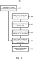
- FIG. 3 depicts a method of vehicle differential analysis.
- the method 300 may be implemented at the vehicle when instructions stored in memory are executed by the processor.
- the vehicle differential analysis functionality 206 described above may implement the method 300.
- the method 300 attempts to determine an action of another vehicle and then checks captured images for visual cues associated with the action. In this way, the method 300 can detect differences between an expected behavior and actual behavior detected in captured images. Detected differences can then be communicated to an external system, for example a department of motor vehicles, vehicle manufacture, etc., for possible corrective action.
- the vehicle performing the method, or at least portions of the method will be referred to the processing vehicle, and the other vehicle for which an action is determined will be referred to as the proximate vehicle.
- the method 300 obtains at least one image associated with a proximate vehicle (302).
- the images may be captured from one or more cameras within, or on, the processing vehicle.
- the camera or cameras may be provided by one or more forward facing or rear facing cameras or side facing cameras.
- the cameras may operate individually or may be operated together providing stereoscopic images.
- the proximate vehicle may be a vehicle that is visible from at least one of the cameras.
- the proximate vehicle may be directly in front of or behind the processing vehicle, beside the processing vehicle, in front of or behind and in different lanes from the processing vehicle or approaching the processing vehicle from an opposite or different direction.
- the images may be constantly captured and one or more of the captured images selected for further processing. Alternatively, images may be captured when required by the method, for example when a particular action has occurred.
- the cameras may maintain a short window of images, for example from between 1 - 10 seconds, so that previous images are available when an action is detected. This may be useful in correlating certain behaviors that may occur before a detected action, for example a turn signal light may be activated prior to a vehicle turning or changing lanes.
- the method 300 obtains sensor data associated with a proximate vehicle (304).
- the sensor data may be collected from one or more sensors including for example LiDAR sensors, radar sensors, ultrasonic sensors as well as other types of possible sensors.
- the obtained sensor data may be received directly from the sensors, for example a ranging senor may provide a range measurement to the proximate vehicle.
- the obtained sensor data may be obtained from processing of sensor data. For example, image data from a stereoscopic camera system may be processed in order to determine range information to the proximate vehicle. Further still, data from multiple sensors may be fused together to provide a single piece of information.
- the obtained sensor data is used to determine a vehicle action of the proximate from the sensor data (306).
- the determination may be based solely on the obtained sensor data, or may additionally be based on further information available at the processing vehicle. For example, in order to determine if the proximate vehicle is braking based on range information, it would also be useful in having information about the processing vehicle's speed. Other additional information that may be used in determining a vehicle action of the proximate vehicle may include GPS positioning information, mapping information steering information, acceleration information, braking information, time of day information, weather conditions. Other information may be used in determining a vehicle action, including for example the type of vehicle such as an emergency vehicle or passenger vehicle, the roadway environment such as during stop and go traffic on a highway or on city streets.
- an expected visual cue associated with the determined vehicle action (8).
- the expected visual cues specify one or more visible behaviors that are associated with the detected behavior in a properly functioning and controlled vehicle. For example, when a vehicle is braking the expected visual cue would be the illumination of all of the brake lights.
- the expected visual cue may depend upon a number of factors such as the time of day. For example a vehicle that is driving on a road way at night time should have lights on while it may not be necessary during the day. Further, the location of the processing vehicle may be used in determining expected visual cues. For example, in certain jurisdictions, day time running lights are required while in other jurisdictions they are not.
- the expected visual cue of a vehicle determined to be driving during the day in a jurisdiction requiring daytime running lights may be different from those in jurisdictions that do not require day time running lights.
- additional information may be used to determine expected visual cues including a type of the proximate vehicle. For example, a passenger vehicle may be expected to have 3 rear brake lights while certain commercial vehicles may not have third brake lights.
- the above visual cues provide an indication of the visual cues expected in a properly functioning vehicle. In certain scenarios detecting a deviation from the expected may be desired; however, it is also possible to provide expected visual cues that are associated with a malfunctioning or poorly maintained vehicle. Excessive exhaust smoke during idling or acceleration may be a visual cue indicative of a possible maintenance issue.
- Table 1 below provides a non-exhaustive list of expected visual cues that may be associated with a detected vehicle action.
- the table also provides illustrative sensor data as well as additional data that may be used in determining the detected action as well as the associated visual cues.
- Table 1 table of possible detected actions and expected visual cues Sensor data of proximate vehicle Additional data Detected Action Expected Visual Cues Range decreasing Processing vehicle's acceleration/deceleration braking Brake lights illuminate Range increasing Processing vehicle's acceleration/deceleration acceleration No brake lights Range increasing Processing vehicle's acceleration/deceleration acceleration Excess exhaust smoke Vehicle presence change Processing vehicle's lane position lane change Turn signals illuminate Vehicle moving Location driving Day-time-running lights on Vehicle moving Time of day driving Lights on Range decreasing Processing vehicle's acceleration/deceleration reversing Reverse lights illuminated
- the obtained images may be used to detected a difference between the expected visual cues and the at least one image (310).
- image processing techniques may be employed to detected brake lights, turn signal indicators, bright lights etc. Particular processing techniques for identifying the presence or absence of the expected visual cues will be apparent to those of ordinary skill in the art.
- an indication of the detected difference may be transmit to a remote location (312).
- the indication may be a predetermined message sent to a remote computer system and may include information about the detected difference as well as identifying information about the proximate vehicle.
- the identifying information may be obtained from license plate information of the proximate vehicle.
- the indication sent to the remote location may be include images of the license plate information, additionally or alternatively, the processing vehicle may perform optical character recognition (OCR) on the license plate image or images and transmit the characters. Further, the indication sent to the remote location may include portions of the data, such as captured images and/or sensor data. As described further below with reference to FIG. 5 , the remote location may receive the indication of the detected differences and provide notifications to one or more locations.
- OCR optical character recognition
- FIG. 4 depicts components of a system for improving vehicle safety using vehicle differential analysis.
- the system 400 may include a plurality of vehicles 104 that include hardware 106 capable of providing vehicle differential analysis functionality as described above.
- the hardware 106 may communicate via a communication infrastructure, depicted as cellular tower 408 and communication networks 410.
- the communications may include one or more items, for example, indications of detected differences, images, as well as identifying information of the proximate vehicle and the processing vehicle.
- the indication may be sent to one or more locations, including, for example a vehicle reporting server 412.
- the vehicle reporting server 412 may implement notification functionality 418 by executing instructions stored in the server's memory by one or more processors.
- the notification functionality 418 is depicted as receiving the indication of detected differences 420, which includes vehicle identification information.
- the notification functionality 418 may determine possible causes of the differences (422). Determining the possible causes may be performed by a look-up to determine possible causes that have been previously associated with the detected differences. Once possible causes are determined, notification information may be determined (424) and the notifications sent to the appropriate locations (426). The notification information may be determined from a vehicle information database or server 414 that stores vehicle identification information (416) including notification information. The stored information may associate a license plate with notification information, such as locations to send notifications to as well as information on types of notifications to provide. Additional identifying information may be associated with the license plate information including, for example vehicle type and color information. In addition to determining notification information associated with the license plate information, additional notification information may be associated with the detected differences or possible causes.
- a detected difference is due to a relatively minor problem such as a burnt out brake light
- only a vehicle owner may be notified according to the notification information allowing the owner to quickly fix the problem and increase the overall safety of the transportation network.
- a 3 rd party responsible for licensing vehicles may be notified.
- other entities may be notified of issues, such as insurers, financers, dealers, etc.
- the system described above has detected differences between expected visual cues associated with a vehicle action and captured images. After detecting possible differences, the vehicle communicates the differences to a remote location.
- the remote location may send one or more notifications to one or more locations.
- the notifications may allow corrective actions to be taken in order to improve the safety of vehicles with detected differences.
- the above system allows autonomous or semi-autonomous vehicles to monitor the operational safety of other vehicles on the roadway, including non-autonomous vehicles. As described further below with reference to FIG. 5 , it is possible for the indications of detected differences to be transmitted to the proximate vehicle.
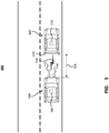
- FIG. 5 depicts an additional roadway environment for improving vehicle safety using vehicle differential analysis.
- the environment 500 is similar to that depicted in FIG. 1 with two vehicles driving on a roadway, however, in contrast to FIG. 1 in which the proximate vehicle 102 was a non-autonomous vehicle the proximate vehicle 502 is a semi-autonomous vehicle, or at least a vehicle having a computing device for communicating with the processing vehicle 104.
- the processing vehicle 104 includes hardware 106 capable of providing the vehicle differential analysis functionality.
- the processing vehicle obtains sensor data such as from radar sensors or LiDAR sensors 512 and captures one or more images, depicted schematically by curved lines 514, of the proximate vehicle 502.
- the processing vehicle may detect an action of the proximate vehicle 502 from the sensor data. For example, when a range 108 to the vehicle is decreasing, the action may be determined to be braking. Based on the action, an associated visual cue may be determined, such as the brake lights being illuminated 510 which can then be detected in the captured images.
- the processing vehicle may transmit an indication of the detected differences to the proximate vehicle's system 516.
- the proximate vehicle 502 may receive the indication of the detected vehicle and may take an appropriate action either to take possible corrective actions or provide a notification to the driver of the vehicle or vehicle reporting system as described in FIG. 4 .
- Some embodiments are directed to a computer program product comprising a computer-readable medium comprising code for causing a computer, or multiple computers, to implement various functions, steps, acts and/or operations, e.g. one or more or all of the steps described above.
- the computer program product can, and sometimes does, include different code for each step to be performed.
- the computer program product may, and sometimes does, include code for each individual step of a method.
- the code may be in the form of machine, e.g., computer, executable instructions stored on a computer-readable medium such as a RAM (Random Access Memory), ROM (Read Only Memory) or other type of storage device.
- some embodiments are directed to a processor configured to implement one or more of the various functions, steps, acts and/or operations of one or more methods described above. Accordingly, some embodiments are directed to a processor, e.g., CPU, configured to implement some or all of the steps of the method(s) described herein.
- the processor may be for use in, e.g., a communications device or other device described in the present application.
Abstract
Description
- The current disclosure relates to detecting possible issues of vehicles on the road using visual characteristics.
- Vehicles may have different levels of automation associated with their driving mode and type of driving scenarios. The level of automation of a vehicle may be between level 0, indicating that there is zero autonomy and the driver is responsible for performing all driving tasks, and
level 5 indicating that the vehicle is fully autonomous and is capable of performing all driving tasks under all conditions without driver input. - Autonomous or semi-autonomous vehicles may improve the safety of roadways by improving driver's reactions, for example with emergency braking, or for fully autonomous vehicles removing the human driver from driving decisions. While autonomous or semi-autonomous vehicles may help improve overall safety of the roadway through improved driving decisions and/or reactions of the autonomous or semi-autonomous vehicles, the overall safety also depends upon all of the vehicles sharing the roadway, regardless of levels of automation, being in good working order.
- It is desirable to be able to monitor vehicles on a roadway in order to improve the overall safety of the vehicles travelling on the roadways.
- The present disclosure will be better understood with reference to the drawings, in which:
-
FIG. 1 depicts a roadway environment in which vehicle differential analysis may be performed; -
FIG. 2 depicts vehicle components for performing vehicle differential analysis; -
FIG. 3 depicts a method of vehicle differential analysis; -
FIG. 4 depicts components of a system for improving vehicle safety using vehicle differential analysis; and -
FIG. 5 depicts an additional roadway environment for improving vehicle safety using vehicle differential analysis. - In accordance with an aspect of the present disclosure there is provided a method for vehicle differential analysis at a computing device in a vehicle, the method comprising: obtaining at least one image associated with a proximate vehicle; obtaining sensor data associated with the proximate vehicle; determining a vehicle action of the proximate vehicle from the sensor data; determining an expected visual cue associated with the determined vehicle action; detecting a difference between the expected visual cue and the at least one image associated with the proximate vehicle; and transmitting an indication of the detected difference through a communications interface to a network.
- In accordance with an aspect of the present disclosure there is provided a computing device in a vehicle for providing differential analysis, the computing device comprising: a processor; and a communications subsystem, wherein the computing device is configured to: obtain at least one image associated with a proximate vehicle; obtain sensor data associated with the proximate vehicle; determine a vehicle action of the proximate vehicle from the sensor data; determine an expected visual cue associated with the determined vehicle action; detect a difference between the expected visual cue and the at least one image associated with the proximate vehicle; and transmit an indication of the detected difference through a communications subsystem to a network.
- Overall safety of roadways may be improved if potential issues of individual vehicles are actively identified and remedied. For example, a vehicle's brake lights provide an important visual indication to other drivers that a vehicle is braking enabling them to react accordingly. A driver of a vehicle may not be aware that the brake lights of their vehicle are not functioning properly and as such may not take corrective actions. Autonomous and semi-autonomous vehicles typically have a range of sensors that can be used to detect the environment around the vehicle, including other vehicles. As described further herein, a vehicle may use differential analysis to detect a difference between an expected visual cue of a proximate vehicle and one or more captured images of the proximate vehicles. The differential analysis may be used to detect potential issues with other vehicles on the roadway and take actions, including for example providing notifications to one or more locations such as a transportation authority, a vehicle owner, etc. As described further below, the differential analysis may determine a proximate vehicles action based on location or range sensor data and then determine an expected visual cue associated with the vehicle action. The expected visual cues can then be compared to captured images in order to detect potential differences between the expected visual cues and the actual visual cues.
-
FIG. 1 depicts a roadway environment in which vehicle differential analysis may be performed. As depicted, theroadway environment 100 may include a number ofvehicles front vehicle 102 depicted inFIG. 1 is assumed to be an automation level 0 vehicle, while thetrailing vehicle 104 is at least an automation level 1 vehicle and includesvehicle hardware 106 comprising a plurality of sensor, such as radar sensors, LIDAR sensors, cameras etc. Thevehicle hardware 106 is depicted as being a single component; however, the hardware may be provided as a number of individual components that are communicatively coupled together, for example by a controller area network (CAN) bus. - The
front vehicle 102 may perform an action, for example applying the brakes. When the brakes of thefront vehicle 102 are applied, whether as a result of the driver depressing the brake pedal or as a result of the autonomous or semi-autonomous vehicle control applying the brakes, rear brake lights will be illuminated as depicted bylines 110 inFIG. 1 . Thetrailing vehicle 104 may capture images, depicted schematically bycurved lines 112, of thefront vehicle 102, which will show the activated brake lights. Additionally, other sensors may detect a change in the distance between the twovehicles 108, depicted schematically bycurved lines 114. When thevehicle 104 detects a braking event from the sensor data, for example thedistance 108 changes faster than a braking threshold, one or more expected visual cues can be determined, which in the case of braking would be illuminated brake lights. The captured images may be processed to identify differences between the captured images and expected visual cues. If there is a difference, for example, no illuminated brake lights were detected, an indication of the detected differences may be transmitted from thevehicle 104 to a remote location over a communication network depicted schematically astower 116. As described further below, with particular reference toFIG. 4 , the remote system may further process the received indication of the detected differences and may, for example, provide notifications to one or more locations. -
FIG. 2 depicts vehicle components for performing vehicle differential analysis. The components depicted inFIG. 2 may provide thehardware components 106 of thevehicle 104 described above with reference toFIG. 1 . The components include at least oneprocessor 202 and associatedmemory unit 204, which although depicted as being separate from the processor may be within, or at least partially within, theprocessor 202. Thememory 204 may include different levels of memory including small and very fast registers or cache memory located within theprocessor 202, large and fast random access memory (RAM), or other types of memory that provide relatively fast access to stored information, as well as very large and relatively slow non-volatile memory such as solid state drives (SSD) or hard disk drives (HDD). Thememory 204 stores data and instructions which when executed by theprocessor 202 configure thehardware components 106 to provide vehicle differential analysis functionality 206. The vehicle differential analysis functionality 206 can determine a vehicle action and expected visual cues and then compare the expected visual cues to captured images. - The
processor 202 may be connected to other components either directly or indirectly. For example, theprocessor 202 may be communicatively coupled to a bus, such as the vehicle's CANbus 208. Additional components can be communicatively coupled to theCAN bus 208 including asensor subsystem 210. Thesensor subsystem 210 may be communicatively coupled to one ormore sensors sensor 210a, aradar sensor 210b, one ormore cameras 210c, one ormore gyroscopes 210d and one ormore accelerometers 210e. Although thesensors 210a-210e are described as being connected tobus 208 through thesensor subsystem 210, it is possible for the sensors to be connected directly to theCAN bus 210, which for example is depicted for anultrasonic sensor 212. Further, as depicted by aGPS sensor 214, it is also possible for one or more sensors to be directly coupled to the processor or coupled to the processor through one or more interface devices. - The
hardware components 106 may also include communication components for communicating with external devices and/or systems. The communication components as being provided by asingle communication subsystem 214, although a plurality of communication components may provide different types of communication including for example cellular radios, Wi-Fi radios, WiMAX radios, Bluetooth radios etc. Thecommunication subsystem 214 may be connected to one ormore antennas 216 for transmitting and receiving signals to and from communication devices. Depending upon the communication type, the communication system may include one or more subscriber identity module (SIM)card 218 to allow communication with a cellular network infrastructure. Although aSIM card 218 is depicted other identifying components including universal subscriber identity modules (USIM), or simply identity modules (IM), or embedded Universal Integrated Circuit Card (eUICC) may be used. - Although illustrative hardware components are depicted in
FIG. 2 , it will be appreciated that more or fewer components may be provided. For example, theprocessor 202 may be provided by a single processor as depicted or may comprise multiple processors that are communicatively coupled together, either by a local communication connections or by one or more communication networks. Further, components, or the functionality provided by components, depicted as being provided as part of the hardware may be provided by other separate devices external from thehardware 106 and coupled together by one or more interfaces. -
FIG. 3 depicts a method of vehicle differential analysis. Themethod 300 may be implemented at the vehicle when instructions stored in memory are executed by the processor. The vehicle differential analysis functionality 206 described above may implement themethod 300. Themethod 300 attempts to determine an action of another vehicle and then checks captured images for visual cues associated with the action. In this way, themethod 300 can detect differences between an expected behavior and actual behavior detected in captured images. Detected differences can then be communicated to an external system, for example a department of motor vehicles, vehicle manufacture, etc., for possible corrective action. For clarity of the following description, the vehicle performing the method, or at least portions of the method, will be referred to the processing vehicle, and the other vehicle for which an action is determined will be referred to as the proximate vehicle. Themethod 300 obtains at least one image associated with a proximate vehicle (302). The images may be captured from one or more cameras within, or on, the processing vehicle. The camera or cameras may be provided by one or more forward facing or rear facing cameras or side facing cameras. The cameras may operate individually or may be operated together providing stereoscopic images. The proximate vehicle may be a vehicle that is visible from at least one of the cameras. The proximate vehicle may be directly in front of or behind the processing vehicle, beside the processing vehicle, in front of or behind and in different lanes from the processing vehicle or approaching the processing vehicle from an opposite or different direction. The images may be constantly captured and one or more of the captured images selected for further processing. Alternatively, images may be captured when required by the method, for example when a particular action has occurred. Further, the cameras may maintain a short window of images, for example from between 1 - 10 seconds, so that previous images are available when an action is detected. This may be useful in correlating certain behaviors that may occur before a detected action, for example a turn signal light may be activated prior to a vehicle turning or changing lanes. - The
method 300 obtains sensor data associated with a proximate vehicle (304). The sensor data may be collected from one or more sensors including for example LiDAR sensors, radar sensors, ultrasonic sensors as well as other types of possible sensors. The obtained sensor data may be received directly from the sensors, for example a ranging senor may provide a range measurement to the proximate vehicle. Additionally or alternatively, the obtained sensor data may be obtained from processing of sensor data. For example, image data from a stereoscopic camera system may be processed in order to determine range information to the proximate vehicle. Further still, data from multiple sensors may be fused together to provide a single piece of information. The obtained sensor data is used to determine a vehicle action of the proximate from the sensor data (306). The determination may be based solely on the obtained sensor data, or may additionally be based on further information available at the processing vehicle. For example, in order to determine if the proximate vehicle is braking based on range information, it would also be useful in having information about the processing vehicle's speed. Other additional information that may be used in determining a vehicle action of the proximate vehicle may include GPS positioning information, mapping information steering information, acceleration information, braking information, time of day information, weather conditions. Other information may be used in determining a vehicle action, including for example the type of vehicle such as an emergency vehicle or passenger vehicle, the roadway environment such as during stop and go traffic on a highway or on city streets. - Once a vehicle action is determined, an expected visual cue associated with the determined vehicle action (308). The expected visual cues specify one or more visible behaviors that are associated with the detected behavior in a properly functioning and controlled vehicle. For example, when a vehicle is braking the expected visual cue would be the illumination of all of the brake lights. The expected visual cue may depend upon a number of factors such as the time of day. For example a vehicle that is driving on a road way at night time should have lights on while it may not be necessary during the day. Further, the location of the processing vehicle may be used in determining expected visual cues. For example, in certain jurisdictions, day time running lights are required while in other jurisdictions they are not. Accordingly, the expected visual cue of a vehicle determined to be driving during the day in a jurisdiction requiring daytime running lights may be different from those in jurisdictions that do not require day time running lights. Further, additional information may be used to determine expected visual cues including a type of the proximate vehicle. For example, a passenger vehicle may be expected to have 3 rear brake lights while certain commercial vehicles may not have third brake lights. The above visual cues provide an indication of the visual cues expected in a properly functioning vehicle. In certain scenarios detecting a deviation from the expected may be desired; however, it is also possible to provide expected visual cues that are associated with a malfunctioning or poorly maintained vehicle. Excessive exhaust smoke during idling or acceleration may be a visual cue indicative of a possible maintenance issue. Table 1 below provides a non-exhaustive list of expected visual cues that may be associated with a detected vehicle action. The table also provides illustrative sensor data as well as additional data that may be used in determining the detected action as well as the associated visual cues.
Table 1: table of possible detected actions and expected visual cues Sensor data of proximate vehicle Additional data Detected Action Expected Visual Cues Range decreasing Processing vehicle's acceleration/deceleration braking Brake lights illuminate Range increasing Processing vehicle's acceleration/deceleration acceleration No brake lights Range increasing Processing vehicle's acceleration/deceleration acceleration Excess exhaust smoke Vehicle presence change Processing vehicle's lane position lane change Turn signals illuminate Vehicle moving Location driving Day-time-running lights on Vehicle moving Time of day driving Lights on Range decreasing Processing vehicle's acceleration/deceleration reversing Reverse lights illuminated - Once one or more expected visual cues have been determined, the obtained images may be used to detected a difference between the expected visual cues and the at least one image (310). For example, image processing techniques may be employed to detected brake lights, turn signal indicators, bright lights etc. Particular processing techniques for identifying the presence or absence of the expected visual cues will be apparent to those of ordinary skill in the art. When a difference is detected between the expected visual cues and the one or more images, an indication of the detected difference may be transmit to a remote location (312). The indication may be a predetermined message sent to a remote computer system and may include information about the detected difference as well as identifying information about the proximate vehicle. The identifying information may be obtained from license plate information of the proximate vehicle. The indication sent to the remote location may be include images of the license plate information, additionally or alternatively, the processing vehicle may perform optical character recognition (OCR) on the license plate image or images and transmit the characters. Further, the indication sent to the remote location may include portions of the data, such as captured images and/or sensor data. As described further below with reference to
FIG. 5 , the remote location may receive the indication of the detected differences and provide notifications to one or more locations. -
FIG. 4 depicts components of a system for improving vehicle safety using vehicle differential analysis. Thesystem 400 may include a plurality ofvehicles 104 that includehardware 106 capable of providing vehicle differential analysis functionality as described above. Thehardware 106 may communicate via a communication infrastructure, depicted ascellular tower 408 andcommunication networks 410. The communications may include one or more items, for example, indications of detected differences, images, as well as identifying information of the proximate vehicle and the processing vehicle. The indication may be sent to one or more locations, including, for example avehicle reporting server 412. Thevehicle reporting server 412 may implementnotification functionality 418 by executing instructions stored in the server's memory by one or more processors. Thenotification functionality 418 is depicted as receiving the indication of detecteddifferences 420, which includes vehicle identification information. Thenotification functionality 418 may determine possible causes of the differences (422). Determining the possible causes may be performed by a look-up to determine possible causes that have been previously associated with the detected differences. Once possible causes are determined, notification information may be determined (424) and the notifications sent to the appropriate locations (426). The notification information may be determined from a vehicle information database orserver 414 that stores vehicle identification information (416) including notification information. The stored information may associate a license plate with notification information, such as locations to send notifications to as well as information on types of notifications to provide. Additional identifying information may be associated with the license plate information including, for example vehicle type and color information. In addition to determining notification information associated with the license plate information, additional notification information may be associated with the detected differences or possible causes. For example, if a detected difference is due to a relatively minor problem such as a burnt out brake light, only a vehicle owner may be notified according to the notification information allowing the owner to quickly fix the problem and increase the overall safety of the transportation network. However, if the cause is due to a more serious problem such as a mechanical issue, a 3rd party responsible for licensing vehicles may be notified. Additionally, other entities may be notified of issues, such as insurers, financers, dealers, etc. - The system described above has detected differences between expected visual cues associated with a vehicle action and captured images. After detecting possible differences, the vehicle communicates the differences to a remote location. The remote location may send one or more notifications to one or more locations. The notifications may allow corrective actions to be taken in order to improve the safety of vehicles with detected differences. The above system allows autonomous or semi-autonomous vehicles to monitor the operational safety of other vehicles on the roadway, including non-autonomous vehicles. As described further below with reference to
FIG. 5 , it is possible for the indications of detected differences to be transmitted to the proximate vehicle. -
FIG. 5 depicts an additional roadway environment for improving vehicle safety using vehicle differential analysis. Theenvironment 500 is similar to that depicted inFIG. 1 with two vehicles driving on a roadway, however, in contrast toFIG. 1 in which theproximate vehicle 102 was a non-autonomous vehicle theproximate vehicle 502 is a semi-autonomous vehicle, or at least a vehicle having a computing device for communicating with theprocessing vehicle 104. - The
processing vehicle 104 includeshardware 106 capable of providing the vehicle differential analysis functionality. The processing vehicle obtains sensor data such as from radar sensors or LiDAR sensors 512 and captures one or more images, depicted schematically by curved lines 514, of theproximate vehicle 502. The processing vehicle may detect an action of theproximate vehicle 502 from the sensor data. For example, when arange 108 to the vehicle is decreasing, the action may be determined to be braking. Based on the action, an associated visual cue may be determined, such as the brake lights being illuminated 510 which can then be detected in the captured images. When the processing detects a difference between the expected visual cues and the captured images, the processing vehicle may transmit an indication of the detected differences to the proximate vehicle'ssystem 516. Theproximate vehicle 502 may receive the indication of the detected vehicle and may take an appropriate action either to take possible corrective actions or provide a notification to the driver of the vehicle or vehicle reporting system as described inFIG. 4 . - Various specific details have been described above. While certain features or functionality may be described in particular detail with regard to one device or component, it will be appreciated that the functionality or features may be applied to other devices or components. Further, although various embodiments of the devices, equipment, functionality, etc. are described herein, the description is intended to provide an understanding of the systems, methods and devices and as such certain aspects may not be described, or not described in as much detail as other aspects. The described systems, methods and devices are not the sole possible implementations, and the various descriptions systems, methods and devices herein will enable one of ordinary skill in the art to apply the teachings to other equivalent implementations without exercising any inventive ingenuity.
- It is understood that the specific order or hierarchy of steps in the processes disclosed is an example of exemplary approaches. Based upon design preferences, it is understood that the specific order or hierarchy of steps in the processes may be rearranged while remaining within the scope of the present disclosure. The accompanying method claims present elements of the various steps in a sample order, and are not meant to be limited to the specific order or hierarchy presented.
- Some embodiments are directed to a computer program product comprising a computer-readable medium comprising code for causing a computer, or multiple computers, to implement various functions, steps, acts and/or operations, e.g. one or more or all of the steps described above. Depending on the embodiment, the computer program product can, and sometimes does, include different code for each step to be performed. Thus, the computer program product may, and sometimes does, include code for each individual step of a method. The code may be in the form of machine, e.g., computer, executable instructions stored on a computer-readable medium such as a RAM (Random Access Memory), ROM (Read Only Memory) or other type of storage device. In addition to being directed to a computer program product, some embodiments are directed to a processor configured to implement one or more of the various functions, steps, acts and/or operations of one or more methods described above. Accordingly, some embodiments are directed to a processor, e.g., CPU, configured to implement some or all of the steps of the method(s) described herein. The processor may be for use in, e.g., a communications device or other device described in the present application.
Claims (15)
- A method for vehicle differential analysis at a computing device in a vehicle, the method comprising:obtaining at least one image associated with a proximate vehicle;obtaining sensor data associated with the proximate vehicle;determining a vehicle action of the proximate vehicle from the sensor data;determining an expected visual cue associated with the determined vehicle action;detecting a difference between the expected visual cue and the at least one image associated with the proximate vehicle; andtransmitting an indication of the detected difference through a communications interface to a network.
- The method of claim 1 further comprising obtaining identification information associated with the proximate vehicle.
- The method of claim 2 wherein the identification information is obtained from the at least one image from a license plate of the proximate vehicle.
- The method of claim 3 further comprising using optical character recognition on a license plate to determine a vehicle identification information.
- The method of claim 4 wherein transmitting the indication of the detected difference through the communications interface to a network includes the identification information.
- The method of any previous claim further comprising performing an action by the vehicle in response to the detected difference.
- The method of claim 6, wherein the vehicle is an autonomous vehicle, and the action comprises increasing a following distance to the proximate vehicle.
- The method of claim 6, wherein the vehicle is an autonomous vehicle, and wherein the action comprises changing lanes.
- The method of any previous claim wherein the sensor data is provided from one or more of a radar unit, an ultrasonic unit, a LIDAR unit and a camera.
- The method of any previous claim wherein the expected visual cue is a brake light or a turn signal of the proximate vehicle.
- The method of any previous claim wherein the image is received from a forward facing camera of the vehicle.
- A computing device in a vehicle for providing differential analysis, the computing device comprising:a processor; anda communications subsystem,wherein the computing device is configured to:obtain at least one image associated with a proximate vehicle;obtain sensor data associated with the proximate vehicle;determine a vehicle action of the proximate vehicle from the sensor data;determine an expected visual cue associated with the determined vehicle action;detect a difference between the expected visual cue and the at least one image associated with the proximate vehicle; andtransmit an indication of the detected difference through a communications subsystem to a network.
- The computing device of claim 12, wherein the computing device is further configured to obtain identification information associated with the proximate vehicle.
- The computing device of claim 12, wherein the computing device is further configured use optical character recognition on a license plate to determine a vehicle identification information.
- The computing device of claim 12, wherein the computing device is further configured perform an action by the vehicle in response to the detected difference.
Applications Claiming Priority (1)
| Application Number | Priority Date | Filing Date | Title |
|---|---|---|---|
| US15/953,135 US10732640B2 (en) | 2018-04-13 | 2018-04-13 | System and method for preforming differential analysis of vehicles |
Publications (1)
| Publication Number | Publication Date |
|---|---|
| EP3553761A1 true EP3553761A1 (en) | 2019-10-16 |
Family
ID=66175227
Family Applications (1)
| Application Number | Title | Priority Date | Filing Date |
|---|---|---|---|
| EP19168910.8A Pending EP3553761A1 (en) | 2018-04-13 | 2019-04-12 | Method and device for performing differential analysis of vehicles |
Country Status (4)
| Country | Link |
|---|---|
| US (2) | US10732640B2 (en) |
| EP (1) | EP3553761A1 (en) |
| CN (1) | CN110386088B (en) |
| CA (1) | CA3039244A1 (en) |
Families Citing this family (3)
| Publication number | Priority date | Publication date | Assignee | Title |
|---|---|---|---|---|
| JP6915512B2 (en) * | 2017-11-28 | 2021-08-04 | トヨタ自動車株式会社 | Server device, faulty vehicle estimation method and faulty vehicle estimation program |
| US10793150B2 (en) * | 2018-09-14 | 2020-10-06 | Wipro Limited | Method and device for controlling vehicle based on neighboring vehicles |
| KR20210133330A (en) * | 2020-04-28 | 2021-11-08 | 주식회사 만도 | driver assistance system and driver assistance method |
Citations (3)
| Publication number | Priority date | Publication date | Assignee | Title |
|---|---|---|---|---|
| EP1341140A1 (en) * | 2002-03-01 | 2003-09-03 | Hitachi Ltd. | Vehicle control apparatus |
| US20170316693A1 (en) * | 2016-04-28 | 2017-11-02 | Sung IL Kim | Traffic information big data operation server using license plate recognition of means of transportation |
| US20170316694A1 (en) * | 2016-05-02 | 2017-11-02 | Hyundai Motor Company | Vehicle and method for supporting driving safety thereof |
Family Cites Families (39)
| Publication number | Priority date | Publication date | Assignee | Title |
|---|---|---|---|---|
| JP3582246B2 (en) * | 1996-08-28 | 2004-10-27 | トヨタ自動車株式会社 | Vehicle running management system |
| US7365769B1 (en) * | 2000-07-06 | 2008-04-29 | Donald Mager | Activating a vehicle's own brake lights and/or brakes when brake lights are sensed in front of the vehicle, including responsively to the proximity of, and/or rate of closure with, a forward vehicle |
| US20030128112A1 (en) * | 2002-01-09 | 2003-07-10 | Cho-Ki Chow | Wireless speed indicating system of automobile |
| US7774137B2 (en) * | 2003-06-24 | 2010-08-10 | Steve Thorne | Speed-monitoring radar-activated brake light |
| DE502006007631D1 (en) * | 2005-02-22 | 2010-09-23 | Adc Automotive Dist Control | METHOD FOR DETECTING THE ACTIVATION OF BRAKE LIGHTS OF PREVAILING VEHICLES |
| JP4914234B2 (en) * | 2007-01-31 | 2012-04-11 | 富士重工業株式会社 | Leading vehicle detection device |
| US7859432B2 (en) * | 2007-05-23 | 2010-12-28 | Che Il Electric Wireing Devices Co., Ltd. | Collision avoidance system based on detection of obstacles in blind spots of vehicle |
| DE102009025545A1 (en) * | 2009-06-15 | 2010-12-16 | Hella Kgaa Hueck & Co. | Method and device for detecting brake light systems |
| EP2423063B1 (en) * | 2010-08-23 | 2013-03-06 | Harman Becker Automotive Systems GmbH | Method of detecting the braking of a vehicle |
| US9607652B2 (en) * | 2010-08-26 | 2017-03-28 | Blast Motion Inc. | Multi-sensor event detection and tagging system |
| US8509982B2 (en) * | 2010-10-05 | 2013-08-13 | Google Inc. | Zone driving |
| KR20120068292A (en) * | 2010-12-17 | 2012-06-27 | 한국전자통신연구원 | Apparatus and method for protecting collision of vehicle |
| US9335162B2 (en) * | 2011-04-19 | 2016-05-10 | Ford Global Technologies, Llc | Trailer length estimation in hitch angle applications |
| US8781170B2 (en) * | 2011-12-06 | 2014-07-15 | GM Global Technology Operations LLC | Vehicle ghosting on full windshield display |
| US10127810B2 (en) * | 2012-06-07 | 2018-11-13 | Zoll Medical Corporation | Vehicle safety and driver condition monitoring, and geographic information based road safety systems |
| CN103903478A (en) * | 2012-12-29 | 2014-07-02 | 富泰华工业(深圳)有限公司 | Vehicle travelling early warning system |
| US9164511B1 (en) * | 2013-04-17 | 2015-10-20 | Google Inc. | Use of detected objects for image processing |
| KR101496544B1 (en) * | 2013-04-19 | 2015-02-26 | 주식회사 만도 | Speeding enforcement method of vehicle using wireless communications |
| JP6281483B2 (en) * | 2014-04-17 | 2018-02-21 | 株式会社デンソー | Failure detection system, information processing apparatus, and vehicle mounting apparatus |
| US9731713B2 (en) * | 2014-09-10 | 2017-08-15 | Volkswagen Ag | Modifying autonomous vehicle driving by recognizing vehicle characteristics |
| JP2016146162A (en) * | 2014-12-04 | 2016-08-12 | 株式会社リコー | Driving determination device, driving determination program, calculation system, detection device, detection system, and detection method and program |
| US10077056B1 (en) * | 2015-04-24 | 2018-09-18 | State Farm Mutual Automobile Insurance Company | Managing self-driving behavior of autonomous or semi-autonomous vehicle based upon actual driving behavior of driver |
| CN106199523B (en) * | 2015-05-27 | 2020-08-28 | 松下知识产权经营株式会社 | Radar apparatus and interference prevention method |
| US9718468B2 (en) * | 2015-10-13 | 2017-08-01 | Verizon Patent And Licensing Inc. | Collision prediction system |
| JP6436054B2 (en) * | 2015-10-26 | 2018-12-12 | 株式会社デンソー | Driving assistance device |
| EP3176725B1 (en) * | 2015-12-03 | 2019-04-10 | Continental Automotive GmbH | Method and device for detecting a braking application of a vehicle |
| US9940530B2 (en) * | 2015-12-29 | 2018-04-10 | Thunder Power New Energy Vehicle Development Company Limited | Platform for acquiring driver behavior data |
| US20170190286A1 (en) * | 2016-01-03 | 2017-07-06 | Edward Yavitz | GPS Vehicle Speed and Velocity Change Indicator |
| US10134278B1 (en) * | 2016-01-22 | 2018-11-20 | State Farm Mutual Automobile Insurance Company | Autonomous vehicle application |
| US9812008B2 (en) * | 2016-02-19 | 2017-11-07 | GM Global Technology Operations LLC | Vehicle detection and tracking based on wheels using radar and vision |
| JP6369487B2 (en) * | 2016-02-23 | 2018-08-08 | トヨタ自動車株式会社 | Display device |
| US10332401B2 (en) * | 2016-03-06 | 2019-06-25 | Foresight Automotive Ltd. | Running vehicle alerting system and method |
| SE542087C2 (en) * | 2016-03-15 | 2020-02-25 | Scania Cv Ab | Method and control unit for vehicle diagnosis |
| US9738125B1 (en) * | 2016-05-17 | 2017-08-22 | Horizon Global Americas Inc. | Communication device, system, and method for active control of external vehicle components |
| US10248874B2 (en) * | 2016-11-22 | 2019-04-02 | Ford Global Technologies, Llc | Brake light detection |
| CN106788727B (en) * | 2017-01-06 | 2019-09-06 | 京东方科技集团股份有限公司 | Vehicle-mounted VISIBLE LIGHT EMISSION system and reception system and communication network |
| CN107146473A (en) * | 2017-07-13 | 2017-09-08 | 京东方科技集团股份有限公司 | A kind of vehicle lane change alarm set, method and the vehicles |
| US10481600B2 (en) * | 2017-09-15 | 2019-11-19 | GM Global Technology Operations LLC | Systems and methods for collaboration between autonomous vehicles |
| US10414334B2 (en) * | 2017-12-08 | 2019-09-17 | Toyota Motor Engineering & Manufacturing North America, Inc. | Automatic hazard light systems and methods |
-
2018
- 2018-04-13 US US15/953,135 patent/US10732640B2/en active Active
-
2019
- 2019-04-05 CA CA3039244A patent/CA3039244A1/en active Pending
- 2019-04-12 CN CN201910298104.8A patent/CN110386088B/en active Active
- 2019-04-12 EP EP19168910.8A patent/EP3553761A1/en active Pending
-
2020
- 2020-07-13 US US16/927,325 patent/US11181924B2/en active Active
Patent Citations (3)
| Publication number | Priority date | Publication date | Assignee | Title |
|---|---|---|---|---|
| EP1341140A1 (en) * | 2002-03-01 | 2003-09-03 | Hitachi Ltd. | Vehicle control apparatus |
| US20170316693A1 (en) * | 2016-04-28 | 2017-11-02 | Sung IL Kim | Traffic information big data operation server using license plate recognition of means of transportation |
| US20170316694A1 (en) * | 2016-05-02 | 2017-11-02 | Hyundai Motor Company | Vehicle and method for supporting driving safety thereof |
Also Published As
| Publication number | Publication date |
|---|---|
| US20190317517A1 (en) | 2019-10-17 |
| CN110386088A (en) | 2019-10-29 |
| US20200341485A1 (en) | 2020-10-29 |
| US10732640B2 (en) | 2020-08-04 |
| CN110386088B (en) | 2024-04-09 |
| CA3039244A1 (en) | 2019-10-13 |
| US11181924B2 (en) | 2021-11-23 |
Similar Documents
| Publication | Publication Date | Title |
|---|---|---|
| CN107415945B (en) | Automatic driving system for evaluating lane change and using method thereof | |
| US10569768B2 (en) | Information processing apparatus, information processing method, and non-transitory recording medium | |
| US11181924B2 (en) | System and method for performing differential analysis of vehicles | |
| CN110400478A (en) | A kind of road condition notification method and device | |
| GB2604514A (en) | Systems and methods for determining road safety | |
| CN110949375B (en) | Information processing system and server | |
| KR20190105150A (en) | Apparatus and method for controlling vehicle platooning | |
| US10754335B2 (en) | Automated driving system | |
| US20180357894A1 (en) | Method for providing drowsiness alerts in vehicles | |
| US10369995B2 (en) | Information processing device, information processing method, control device for vehicle, and control method for vehicle | |
| JP7362733B2 (en) | Automated crowdsourcing of road environment information | |
| US10977882B1 (en) | Driver health profile | |
| SE538984C2 (en) | Determination of lane position | |
| CN110562269A (en) | Method for processing fault of intelligent driving vehicle, vehicle-mounted equipment and storage medium | |
| DE102015225094A1 (en) | Apparatus and method for providing a notification signal and apparatus and method for determining traffic data | |
| CN111161587A (en) | Vehicle control method | |
| US20200410788A1 (en) | Management apparatus, vehicle, inspection apparatus, and vehicle inspection system and inforamtion processing method therefor | |
| US11188071B2 (en) | Driving control system | |
| JP2021088289A (en) | Drive assist device | |
| US10423166B2 (en) | Method and apparatus for furnishing a signal for operating at least two vehicles along a first trajectory | |
| KR20170082374A (en) | Lane detection apparatus | |
| CN110395270B (en) | Automatic following driving system | |
| CN114333414A (en) | Parking yield detection device, parking yield detection system, and recording medium | |
| JP2022027305A (en) | Risky driving detection device, risky driving detection system, and risky driving detection program | |
| CN112349093A (en) | Vehicle early warning method and device fused with V2X sensor |
Legal Events
| Date | Code | Title | Description |
|---|---|---|---|
| PUAI | Public reference made under article 153(3) epc to a published international application that has entered the european phase |
Free format text: ORIGINAL CODE: 0009012 |
|
| STAA | Information on the status of an ep patent application or granted ep patent |
Free format text: STATUS: THE APPLICATION HAS BEEN PUBLISHED |
|
| AK | Designated contracting states |
Kind code of ref document: A1 Designated state(s): AL AT BE BG CH CY CZ DE DK EE ES FI FR GB GR HR HU IE IS IT LI LT LU LV MC MK MT NL NO PL PT RO RS SE SI SK SM TR |
|
| AX | Request for extension of the european patent |
Extension state: BA ME |
|
| STAA | Information on the status of an ep patent application or granted ep patent |
Free format text: STATUS: REQUEST FOR EXAMINATION WAS MADE |
|
| 17P | Request for examination filed |
Effective date: 20200313 |
|
| RBV | Designated contracting states (corrected) |
Designated state(s): AL AT BE BG CH CY CZ DE DK EE ES FI FR GB GR HR HU IE IS IT LI LT LU LV MC MK MT NL NO PL PT RO RS SE SI SK SM TR |
|
| STAA | Information on the status of an ep patent application or granted ep patent |
Free format text: STATUS: EXAMINATION IS IN PROGRESS |
|
| 17Q | First examination report despatched |
Effective date: 20220311 |
|
| P01 | Opt-out of the competence of the unified patent court (upc) registered |
Effective date: 20230518 |