EP3553743A2 - Systems and methods for image processing - Google Patents
Systems and methods for image processing Download PDFInfo
- Publication number
- EP3553743A2 EP3553743A2 EP19168808.4A EP19168808A EP3553743A2 EP 3553743 A2 EP3553743 A2 EP 3553743A2 EP 19168808 A EP19168808 A EP 19168808A EP 3553743 A2 EP3553743 A2 EP 3553743A2
- Authority
- EP
- European Patent Office
- Prior art keywords
- bone
- fracture
- image
- images
- bone fracture
- Prior art date
- Legal status (The legal status is an assumption and is not a legal conclusion. Google has not performed a legal analysis and makes no representation as to the accuracy of the status listed.)
- Pending
Links
Images


Classifications
-
- G—PHYSICS
- G06—COMPUTING OR CALCULATING; COUNTING
- G06T—IMAGE DATA PROCESSING OR GENERATION, IN GENERAL
- G06T7/00—Image analysis
- G06T7/0002—Inspection of images, e.g. flaw detection
- G06T7/0012—Biomedical image inspection
-
- G—PHYSICS
- G16—INFORMATION AND COMMUNICATION TECHNOLOGY [ICT] SPECIALLY ADAPTED FOR SPECIFIC APPLICATION FIELDS
- G16H—HEALTHCARE INFORMATICS, i.e. INFORMATION AND COMMUNICATION TECHNOLOGY [ICT] SPECIALLY ADAPTED FOR THE HANDLING OR PROCESSING OF MEDICAL OR HEALTHCARE DATA
- G16H50/00—ICT specially adapted for medical diagnosis, medical simulation or medical data mining; ICT specially adapted for detecting, monitoring or modelling epidemics or pandemics
- G16H50/20—ICT specially adapted for medical diagnosis, medical simulation or medical data mining; ICT specially adapted for detecting, monitoring or modelling epidemics or pandemics for computer-aided diagnosis, e.g. based on medical expert systems
-
- G—PHYSICS
- G06—COMPUTING OR CALCULATING; COUNTING
- G06N—COMPUTING ARRANGEMENTS BASED ON SPECIFIC COMPUTATIONAL MODELS
- G06N20/00—Machine learning
-
- G—PHYSICS
- G06—COMPUTING OR CALCULATING; COUNTING
- G06T—IMAGE DATA PROCESSING OR GENERATION, IN GENERAL
- G06T15/00—Three-dimensional [3D] image rendering
- G06T15/10—Geometric effects
- G06T15/20—Perspective computation
- G06T15/205—Image-based rendering
-
- G—PHYSICS
- G06—COMPUTING OR CALCULATING; COUNTING
- G06T—IMAGE DATA PROCESSING OR GENERATION, IN GENERAL
- G06T7/00—Image analysis
- G06T7/0002—Inspection of images, e.g. flaw detection
- G06T7/0012—Biomedical image inspection
- G06T7/0014—Biomedical image inspection using an image reference approach
-
- G—PHYSICS
- G06—COMPUTING OR CALCULATING; COUNTING
- G06T—IMAGE DATA PROCESSING OR GENERATION, IN GENERAL
- G06T7/00—Image analysis
- G06T7/10—Segmentation; Edge detection
-
- G—PHYSICS
- G16—INFORMATION AND COMMUNICATION TECHNOLOGY [ICT] SPECIALLY ADAPTED FOR SPECIFIC APPLICATION FIELDS
- G16H—HEALTHCARE INFORMATICS, i.e. INFORMATION AND COMMUNICATION TECHNOLOGY [ICT] SPECIALLY ADAPTED FOR THE HANDLING OR PROCESSING OF MEDICAL OR HEALTHCARE DATA
- G16H30/00—ICT specially adapted for the handling or processing of medical images
- G16H30/20—ICT specially adapted for the handling or processing of medical images for handling medical images, e.g. DICOM, HL7 or PACS
-
- G—PHYSICS
- G16—INFORMATION AND COMMUNICATION TECHNOLOGY [ICT] SPECIALLY ADAPTED FOR SPECIFIC APPLICATION FIELDS
- G16H—HEALTHCARE INFORMATICS, i.e. INFORMATION AND COMMUNICATION TECHNOLOGY [ICT] SPECIALLY ADAPTED FOR THE HANDLING OR PROCESSING OF MEDICAL OR HEALTHCARE DATA
- G16H30/00—ICT specially adapted for the handling or processing of medical images
- G16H30/40—ICT specially adapted for the handling or processing of medical images for processing medical images, e.g. editing
-
- G—PHYSICS
- G06—COMPUTING OR CALCULATING; COUNTING
- G06T—IMAGE DATA PROCESSING OR GENERATION, IN GENERAL
- G06T2207/00—Indexing scheme for image analysis or image enhancement
- G06T2207/10—Image acquisition modality
- G06T2207/10072—Tomographic images
-
- G—PHYSICS
- G06—COMPUTING OR CALCULATING; COUNTING
- G06T—IMAGE DATA PROCESSING OR GENERATION, IN GENERAL
- G06T2207/00—Indexing scheme for image analysis or image enhancement
- G06T2207/10—Image acquisition modality
- G06T2207/10072—Tomographic images
- G06T2207/10081—Computed x-ray tomography [CT]
-
- G—PHYSICS
- G06—COMPUTING OR CALCULATING; COUNTING
- G06T—IMAGE DATA PROCESSING OR GENERATION, IN GENERAL
- G06T2207/00—Indexing scheme for image analysis or image enhancement
- G06T2207/10—Image acquisition modality
- G06T2207/10072—Tomographic images
- G06T2207/10088—Magnetic resonance imaging [MRI]
-
- G—PHYSICS
- G06—COMPUTING OR CALCULATING; COUNTING
- G06T—IMAGE DATA PROCESSING OR GENERATION, IN GENERAL
- G06T2207/00—Indexing scheme for image analysis or image enhancement
- G06T2207/10—Image acquisition modality
- G06T2207/10072—Tomographic images
- G06T2207/10104—Positron emission tomography [PET]
-
- G—PHYSICS
- G06—COMPUTING OR CALCULATING; COUNTING
- G06T—IMAGE DATA PROCESSING OR GENERATION, IN GENERAL
- G06T2207/00—Indexing scheme for image analysis or image enhancement
- G06T2207/20—Special algorithmic details
- G06T2207/20081—Training; Learning
-
- G—PHYSICS
- G06—COMPUTING OR CALCULATING; COUNTING
- G06T—IMAGE DATA PROCESSING OR GENERATION, IN GENERAL
- G06T2207/00—Indexing scheme for image analysis or image enhancement
- G06T2207/20—Special algorithmic details
- G06T2207/20084—Artificial neural networks [ANN]
-
- G—PHYSICS
- G06—COMPUTING OR CALCULATING; COUNTING
- G06T—IMAGE DATA PROCESSING OR GENERATION, IN GENERAL
- G06T2207/00—Indexing scheme for image analysis or image enhancement
- G06T2207/30—Subject of image; Context of image processing
- G06T2207/30004—Biomedical image processing
- G06T2207/30008—Bone
-
- G—PHYSICS
- G06—COMPUTING OR CALCULATING; COUNTING
- G06T—IMAGE DATA PROCESSING OR GENERATION, IN GENERAL
- G06T2215/00—Indexing scheme for image rendering
- G06T2215/06—Curved planar reformation of 3D line structures
Definitions
- the present disclosure generally relates to medical imaging, and in particular, to systems and methods for bone fracture detection by way of image processing.
- CT computed tomography
- doctors need to observe and analyze a plurality of CT images to identify bone fracture based on the experience of the doctor.
- doctors need to observe and analyze a plurality of CT images to identify bone fracture in each rib.
- the doctors need to study and analyze a plurality of CT images, which rely on the experience of the doctors, and make the fracture detection laborious and subjective. Therefore, it is desirable to provide systems and/or methods for automated bone fracture detection to improve the efficiency and the accuracy of bone fracture detection.
- a computer aided diagnosis system for bone fracture detection may include one or more storage devices and one or more processors configured to communicate with the one or more storage devices.
- the one or more storage devices may include a set of instructions.
- the one or more processors may be directed to perform one or more of the following operations.
- the one or more processors may obtain one or more medical images related to one or more bones.
- the one or more processors may obtain a fracture detection model generated based on a machine learning model.
- the one or more processors may detect, for at least one of the one or more medical images, one or more bone fracture regions of the one or more bones in the medical image using the fracture detection model.
- the fracture detection model may be obtained by performing operations including: obtaining training images in which bone fractures are marked; and determining the fracture detection model by training a preliminary model using the training images.
- the one or more processors may detect one or more candidate fracture regions in the medical image using the fracture detection model.
- the one or more processors may obtain the one or more bone fracture regions by removing one or more false positive regions from the one or more candidate fracture regions using a bone mask related to the one or more bones.
- the one or more processors may display a marker of the one or more bone fracture regions in the at least one of the one or more medical images.
- the one or more processors may determine a type of bone fracture in the one or more bone fracture regions using the fracture detection model.
- the one or more medical images may include multiple medical images taken at different slices of the one or more bones.
- the one or more processors may determine whether there are at least two of the multiple medical images in each of which the one or more bone fracture regions are detected.
- the one or more processors may determine a distance between the detected bone fracture regions in the at least two of the multiple medical images in response to a determination that there are at least two of the multiple medical images in each of which the one or more bone fracture regions are detected.
- the one or more processors may determine whether the distance is less than a distance threshold.
- the one or more processors may combine the detected bone fracture regions in the at least two of the multiple medical images in response to a determination that the distance is less than the distance threshold.
- the detected bone fracture regions in the at least two of the multiple medical images may be deemed to relate to a same bone fracture.
- the one or more processors may reconstruct one or more bone images based on the one or more detected bone fracture regions or the combined bone fracture region.
- the one or more processors may display a marker of the one or more detected bone fracture regions or the combined bone fracture region in the one or more bone images.
- the one or more bone images may include at least one of a curved planar reconstruction (CPR) image, a multiplanar reconstruction (MPR) image, and a three-dimensional (3D) rendering image.
- CPR curved planar reconstruction
- MPR multiplanar reconstruction
- 3D three-dimensional
- the one or more processors may extract a centerline of at least one of the one or more bones based on the one or more medical images.
- the one or more processors may generate a stretched CPR image based on the centerline of the bone.
- the one or more processors may display a management list for managing at least one of one or more bone masks related to the one or more bones and information related to the one or more detected bone fracture regions.
- the one or more processors may receive an instruction related to selecting at least one of the one or more bones.
- the instruction may be generated through the management list or the 3D rendering image.
- the one or more processors may display at least one of the stretched CPR image and one or more MPR images related to the at least one selected bone based on the instruction.
- the fracture detection model may be obtained based on a convolutional neural network (CNN).
- CNN convolutional neural network
- the one or more medical images may include multiple medical images.
- the one or more processors may receive an instruction of selecting, for display, a first location in a first medical image of the one or more medical images.
- the one or more processors may simultaneously display the first medical image, or a portion thereof, including the selected first location and a second medical image, or a portion thereof, of the one or more medical image.
- the second medical image may include a second location corresponding to the first location.
- the displaying of the second medical image, or a portion thereof may include displaying a marker of the second location.
- the one or more processors may generate, for at least one of the one or more medical images, a target image including the one or more bones by segmenting the one or more bones from the medical image.
- a computer aided diagnosis method for bone fracture detection may include one or more of the following operations.
- One or more processors may obtain one or more medical images related to one or more bones.
- the one or more processors may obtain a fracture detection model generated based on a machine learning model.
- the one or more processors may detect, for at least one of the one or more medical images, one or more bone fracture regions of the one or more bones in the medical image using the fracture detection model.
- a computer aided diagnosis system for bone fracture detection may include an obtaining module configured to obtain one or more medical images related to one or more bones.
- the system may also include a processing module configured to obtain a fracture detection model generated based on a machine learning model and detect, for at least one of the one or more medical images, one or more bone fracture regions of the one or more bones in the medical image using the fracture detection model.
- a non-transitory computer readable medium may comprise at least one set of instructions for bone fracture detection.
- the at least one set of instructions may be executed by one or more processors of a computer server.
- the one or more processors may obtain one or more medical images related to one or more bones.
- the one or more processors may obtain a fracture detection model generated based on a machine learning model.
- the one or more processors may detect, for at least one of the one or more medical images, one or more bone fracture regions of the one or more bones in the medical image using the fracture detection model.
- An aspect of the present disclosure relates to systems and methods for automated bone fracture detection by way of image processing.
- bone fractures in medical images may be automatically detected using a bone fracture detection model.
- the fracture detection model may be developed on the basis of a machine learning model.
- doctors may need to analyze a plurality of medical images and use their own experience to detect bone fractures represented in the images.
- the methods and/or systems for fracture detection in the present disclosure may achieve automated detection using a fracture detection model, which may reduce manual operations and the time to perform the fracture detection, improve the efficiency and/or the accuracy of the fracture detection, and/or obtain a more objective fracture detection result.
- a marker of the detected bone fracture region may be displayed in an original image generated based on raw data obtained during a scan of the bone (e.g., a rib), a curved planar reconstruction (CPR) image (e.g., a stretched CPR image), a multiplanar reconstruction (MPR) image, a three-dimensional (3D) rendering image, or the like.
- CPR curved planar reconstruction
- MPR multiplanar reconstruction
- 3D three-dimensional
- the rib may be displayed from a view parallel to the rib (e.g., along the extending direction of the rib), which may make it relatively easy for doctors to observe the entire and real morphology of the rib in the CPR image.
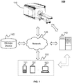
- FIG. 1 is a schematic diagram illustrating an exemplary computer aided diagnosis system 100 according to some embodiments of the present disclosure.
- the computer aided diagnosis system 100 may include an imaging device 110, a network 120, a user terminal 130, a processing device 140, and a storage device 150.
- the components of the computer aided diagnosis system 100 may be connected in one or more of various ways. Mere by way of example, as illustrated in FIG. 1 , the imaging device 110 may be connected to the processing device 140 through the network 120. As another example, the imaging device 110 may be connected to the processing device 140 directly (as indicated by the bi-directional arrow in dotted lines linking the imaging device 110 and the processing device 140).
- the storage device 150 may be connected to the processing device 140 directly or through the network 120.
- a terminal device e.g., 131, 132, 133, etc.
- the processing device 140 directly (as indicated by the bi-directional arrow in dotted lines linking the user terminal 130 and the processing device 140) or through the network 120.
- the imaging device 110 may scan an object located within its detection region and generate a plurality of data relating to the object.
- the object may include a patient, a man-made object, etc.
- the object may include a specific portion, organ, and/or tissue of a patient.
- the object may include head, brain, neck, body, shoulder, arm, thorax, cardiac, stomach, blood vessel, soft tissue, knee, feet, bones, or the like, or any combination thereof.
- the imaging device 110 may include a magnetic resonance imaging (MRI) device, a positron emission tomography (PET) device, a computed tomography (CT) device, a radiography device, or the like, or any combination thereof.
- MRI magnetic resonance imaging
- PET positron emission tomography
- CT computed tomography
- radiography device or the like, or any combination thereof.
- the network 120 may include any suitable network that can facilitate the exchange of information and/or data for the computer aided diagnosis system 100.
- one or more components of the computer aided diagnosis system 100 e.g., the imaging device 110, the user terminal 130, the processing device 140, or the storage device 150
- the processing device 140 may obtain raw data from the imaging device 110 via the network 120.
- the network 120 may be any type of wired or wireless network, or a combination thereof.
- the network 120 may be and/or include a public network (e.g., the Internet), a private network (e.g., a local area network (LAN), a wide area network (WAN)), etc.), a wired network (e.g., an Ethernet network), a wireless network (e.g., an 802.11 network, a Wi-Fi network, etc.), a cellular network (e.g., a Long Term Evolution (LTE) network), a frame relay network, a virtual private network (“VPN”), a satellite network, a telephone network, routers, hubs, switches, server computers, and/or any combination thereof.
- a public network e.g., the Internet
- a private network e.g., a local area network (LAN), a wide area network (WAN)), etc.
- a wired network e.g., an Ethernet network
- a wireless network e.g., an 802.11 network, a Wi-Fi network, etc.
- the network 120 may include a cable network, a wireline network, a fiber-optic network, a telecommunications network, an intranet, a wireless local area network (WLAN), a metropolitan area network (MAN), a public telephone switched network (PSTN), a BluetoothTM network, a ZigBeeTM network, a near field communication (NFC) network, or the like, or any combination thereof.
- the network 120 may include one or more network access points.
- the network 120 may include wired and/or wireless network access points such as base stations and/or internet exchange points through which one or more components of the computer aided diagnosis system 100 may be connected to the network 120 to exchange data and/or information.
- the user terminal 130 may include a mobile device 131, a tablet computer 132, a laptop computer 133, or the like, or any combination thereof.
- the mobile device 131 may include a smart home device, a wearable device, a smart mobile device, a virtual reality device, an augmented reality device, or the like, or any combination thereof.
- the smart home device may include a smart lighting device, a control device of an intelligent electrical apparatus, a smart monitoring device, a smart television, a smart video camera, an interphone, or the like, or any combination thereof.
- the wearable device may include a smart bracelet, smart footgear, a pair of smart glasses, a smart helmet, a smart watch, smart clothing, a smart backpack, a smart accessory, or the like, or any combination thereof.
- the smart mobile device may include a smartphone, a personal digital assistant (PDA), a gaming device, a navigation device, a point of sale (POS) device, or the like, or any combination thereof.
- the virtual reality device and/or the augmented reality device may include a virtual reality helmet, a virtual reality glass, a virtual reality patch, an augmented reality helmet, an augmented reality glass, an augmented reality patch, or the like, or any combination thereof.
- the virtual reality device and/or the augmented reality device may include a GoogleTM Glass, an Oculus Rift, a Hololens, a Gear VR, etc.
- the user terminal 130 may remotely operate the imaging device 110 and/or the processing device 140.
- the user terminal 130 may operate the imaging device 110 and/or the processing device 140 via a wireless connection.
- the user terminal 130 may receive information and/or instructions inputted by a user, and send the received information and/or instructions to the imaging device 110 or to the processing device 140 via the network 120.
- the user terminal 130 may receive data and/or information from the processing device 140.
- the user terminal 130 may be part of the processing device 140.
- the user terminal 130 may be omitted.
- the processing device 140 may process data and/or information obtained from the imaging device 110, the user terminal 130, and/or the storage device 150.
- the processing device 140 may detect a bone fracture in one or more medical images by processing the one or more medical images.
- the processing device 140 may be a single server or a server group. The server group may be centralized or distributed.
- the processing device 140 may be local or remote.
- the processing device 140 may access information and/or data stored in or acquired by the imaging device 110, the user terminal 130, and/or the storage device 150 via the network 120.
- the processing device 140 may be directly connected to the imaging device 110, the user terminal 130, and/or the storage device 150 to access stored or acquired information and/or data.
- the processing device 140 may be implemented on a cloud platform.
- the cloud platform may include a private cloud, a public cloud, a hybrid cloud, a community cloud, a distributed cloud, an inter-cloud, a multi-cloud, or the like, or any combination thereof.
- the processing device 140 may be implemented on a computing device 200 having one or more components illustrated in FIG. 2 in the present disclosure.
- the storage device 150 may store data and/or instructions.
- the storage device 150 may store data obtained from the imaging device 110, the user terminal 130 and/or the processing device 140.
- the storage device 150 may store one or more medical images generated by the processing device 140 based on raw data obtained from the imaging device 110.
- the storage device 150 may store data and/or instructions that the processing device 140 may execute or use to perform exemplary methods described in the present disclosure.
- the storage device 150 may store instructions that the processing device 140 may execute to detect bone fractures in one or more medical images by processing the one or more medical images.
- the storage device 150 may include a mass storage device, a removable storage device, a volatile read-and-write memory, a read-only memory (ROM), or the like, or any combination thereof.
- exemplary mass storage may include a magnetic disk, an optical disk, a solid-state drive, etc.
- Exemplary removable storage may include a flash drive, a floppy disk, an optical disk, a memory card, a zip disk, a magnetic tape, etc.
- Exemplary volatile read-and-write memory may include a random access memory (RAM).
- Exemplary RAM may include a dynamic RAM (DRAM), a double date rate synchronous dynamic RAM (DDR SDRAM), a static RAM (SRAM), a thyristor RAM (T-RAM), and a zero-capacitor RAM (Z-RAM), etc.
- Exemplary ROM may include a mask ROM (MROM), a programmable ROM (PROM), an erasable programmable ROM (PEROM), an electrically erasable programmable ROM (EEPROM), a compact disk ROM (CD-ROM), and a digital versatile disk ROM, etc.
- the storage device 150 may be implemented on a cloud platform.
- the cloud platform may include a private cloud, a public cloud, a hybrid cloud, a community cloud, a distributed cloud, an inter-cloud, a multi-cloud, or the like, or any combination thereof.
- the storage device 150 may be connected to the network 120 to communicate with one or more components of the computer aided diagnosis system 100 (e.g., the imaging device 110, the processing device 140, the user terminal 130, etc.). One or more components of the computer aided diagnosis system 100 may access the data or instructions stored in the storage device 150 via the network 120. In some embodiments, the storage device 150 may be directly connected to or communicate with one or more components of the computer aided diagnosis system 100 (e.g., the imaging device 110, the processing device 140, the user terminal 130, etc.). In some embodiments, the storage device 150 may be part of the processing device 140.
- FIG. 2 is a schematic diagram illustrating exemplary hardware and/or software components of a computing device on which the processing device 140 may be implemented according to some embodiments of the present disclosure.
- the computing device 200 may include a processor 210, a storage 220, an input/output (I/O) 230, and a communication port 240.
- I/O input/output
- the processor 210 may execute computer instructions (program code) and perform functions of the processing device140 in accordance with techniques described herein.
- the computer instructions may include routines, programs, objects, components, signals, data structures, procedures, modules, and functions, which perform particular functions described herein.
- the processor 210 may detect bone fractures in one or more medical images by processing the one or more medical images.
- the processor 210 may include a microcontroller, a microprocessor, a reduced instruction set computer (RISC), an application specific integrated circuits (ASICs), an application-specific instruction-set processor (ASIP), a central processing unit (CPU), a graphics processing unit (GPU), a physics processing unit (PPU), a microcontroller unit, a digital signal processor (DSP), a field programmable gate array (FPGA), an advanced RISC machine (ARM), a programmable logic device (PLD), any circuit or processor capable of executing one or more functions, or the like, or any combinations thereof.
- RISC reduced instruction set computer
- ASICs application specific integrated circuits
- ASIP application-specific instruction-set processor
- CPU central processing unit
- GPU graphics processing unit
- PPU physics processing unit
- DSP digital signal processor
- FPGA field programmable gate array
- ARM advanced RISC machine
- PLD programmable logic device
- the computing device 200 in the present disclosure may also include multiple processors, and thus operations of a method that are performed by one processor as described in the present disclosure may also be jointly or separately performed by the multiple processors.
- the processor of the computing device 200 executes both operations A and B
- operations A and step B may also be performed by two different processors jointly or separately in the computing device 200 (e.g., a first processor executes operation A and a second processor executes operation B, or the first and second processors jointly execute operations A and B).
- the storage 220 may store data/information obtained from the imaging device 110, the user terminal 130, the storage device 150, or any other component of the computer aided diagnosis system 100.
- the storage 220 may include a mass storage device, a removable storage device, a volatile read-and-write memory, a read-only memory (ROM), or the like, or any combination thereof.
- the mass storage device may include a magnetic disk, an optical disk, a solid-state drive, etc.
- the removable storage device may include a flash drive, a floppy disk, an optical disk, a memory card, a zip disk, a magnetic tape, etc.
- the volatile read-and-write memory may include a random access memory (RAM).
- the RAM may include a dynamic RAM (DRAM), a double date rate synchronous dynamic RAM (DDR SDRAM), a static RAM (SRAM), a thyristor RAM (T-RAM), and a zero-capacitor RAM (Z-RAM), etc.
- the ROM may include a mask ROM (MROM), a programmable ROM (PROM), an erasable programmable ROM (PEROM), an electrically erasable programmable ROM (EEPROM), a compact disk ROM (CD-ROM), and a digital versatile disk ROM, etc.
- the storage 220 may store one or more programs and/or instructions to perform exemplary methods described in the present disclosure.
- the storage 220 may store a program for the processing device 140 to detect bone fractures in one or more medical images by processing the one or more medical images.
- the I/O 230 may input or output signals, data, or information. In some embodiments, the I/O 230 may enable a user interaction with the processing device 140. In some embodiments, the I/O 230 may include an input device and an output device. Exemplary input devices may include a keyboard, a mouse, a touch screen, a microphone, a trackball, or the like, or a combination thereof. Exemplary output devices may include a display device, a loudspeaker, a printer, a projector, or the like, or a combination thereof.
- Exemplary display devices may include a liquid crystal display (LCD), a light-emitting diode (LED)-based display, a flat panel display, a curved screen, a television device, a cathode ray tube (CRT), or the like, or a combination thereof.
- LCD liquid crystal display
- LED light-emitting diode
- CRT cathode ray tube
- a user e.g., an operator of the processing device 140 may input data related to an object (e.g., a patient) that is being/to be imaged/scanned through the I/O 230.
- the data related to the object may include identification information (e.g., the name, age, gender, medical history, contract information, physical examination result, etc.) and/or the test information including the nature of the scan that must be performed.
- the user may also input parameters needed for the operation of the imaging device 110. For example, for CT imaging, the user may input a scan protocol including a scanning time, a region of interest (ROI), a rotation speed of the imaging device 110, a voltage/current intensity, etc.
- the I/O may also display medical images.
- the communication port 240 may be connected to a network (e.g., the network 120) to facilitate data communications.
- the communication port 240 may establish connections between the processing device140 and the imaging device 110, the user terminal 130, or the storage device 150.
- the connection may be a wired connection, a wireless connection, or a combination of both that enables data transmission and reception.
- the wired connection may include an electrical cable, an optical cable, a telephone wire, or the like, or any combination thereof.
- the wireless connection may include Bluetooth, Wi-Fi, WiMax, WLAN, ZigBee, mobile network (e.g., 3G, 4G, 5G, etc.), or the like, or a combination thereof.
- the communication port 240 may be a standardized communication port, such as RS232, RS485, etc. In some embodiments, the communication port 240 may be a specially designed communication port. For example, the communication port 240 may be designed in accordance with the digital imaging and communications in medicine (DICOM) protocol.
- DICOM digital imaging and communications in medicine
- FIG. 3 is a schematic diagram illustrating exemplary hardware and/or software components of a mobile device on which the user terminal 130 may be implemented according to some embodiments of the present disclosure.
- the mobile device 300 may include a communication platform 310, a display 320, a graphics processing unit (GPU) 330, a central processing unit(CPU) 340, an I/O 350, a memory 360, and a storage 390.
- any other suitable component including but not limited to a system bus or a controller (not shown), may also be included in the mobile device 300.
- a mobile operating system 370 e.g., iOS, Android, Windows Phone, etc.
- the applications 380 may include a browser or any other suitable mobile apps for receiving and rendering information relating to image processing or other information from the processing device 140.
- User interactions with the information stream may be achieved via the I/O 350 and provided to the processing device140 and/or other components of the computer aided diagnosis system 100 via the network 120.
- computer hardware platforms may be used as the hardware platform(s) for one or more of the elements described herein.
- the hardware elements, operating systems and programming languages of such computers are conventional in nature, and it is presumed that those skilled in the art are adequately familiar therewith to adapt those technologies to the blood pressure monitoring as described herein.
- a computer with user interface elements may be used to implement a personal computer (PC) or another type of work station or terminal device, although a computer may also act as a server if appropriately programmed. It is believed that those skilled in the art are familiar with the structure, programming and general operation of such computer equipment and as a result the drawings should be self-explanatory.
- the methods and/or systems for bone fracture detection in the present disclosure are described with reference to ribs as an example. It should be noted that the methods and/or systems for bone fracture detection described below are merely some examples or implementations. For persons having ordinary skills in the art, the methods and/or systems for bone fracture detection in the present disclosure may be applied to bone fracture detection of other kinds of bones, such as tibias, spine, etc.
- an image, or a portion thereof corresponding to an object (e.g., tissue, an organ, a tumor, etc.) may be referred to as an image, or a portion of thereof (e.g., a region) of or including the object, or the object itself.
- an image e.g., tissue, an organ, a tumor, etc.
- a region in an image that corresponds to or represents a bone may be described as that the region includes a bone.
- an image of or including a bone may be referred to a bone image, or simply bone.
- a portion of an image corresponding to or representing an object is processed may be described as the object is processed.
- a portion of an image corresponding to a bone is segmented from the rest of the image may be described as that the bone is segmented from the image.
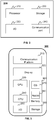
- FIG. 4 is a schematic block diagram illustrating an exemplary processing device according to some embodiments of the present disclosure.
- the processing device 140 may include an obtaining module 410, a segmentation module 420, and a processing module 430.
- the obtaining module 410 may be configured to obtain a medical image related to one or more ribs.
- the segmentation module 420 may be configured to generate a target image including the one or more ribs by segmenting the one or more ribs from the medical image.
- the processing module 430 may be configured to detect a bone fracture region of the one or more ribs in the target image using a fracture detection model.
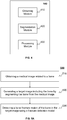
- FIG. 5A is a flowchart illustrating an exemplary process for detecting bone fracture according to some embodiments of the present disclosure.
- the process 500 may be implemented in the computer aided diagnosis system 100 illustrated in FIG. 1 .
- the process 500 may be stored in a storage medium (e.g., the storage device 150, or the storage 220 of the processing device 140) in the form of instructions, and can be invoked and/or executed by the processing device 140 (e.g., the processor 210 of the processing device 140, or one or more modules in the processing device 140 illustrated in FIG. 4 ).
- the operations of the illustrated process 500 presented below are intended to be illustrative. In some embodiments, the process 500 may be accomplished with one or more additional operations not described, and/or without one or more of the operations discussed. Additionally, the order in which the operations of the process 500 as illustrated in FIG. 5 and described below is not intended to be limiting.
- the processing device 140 may obtain a medical image related to one or more ribs.
- the medical image may include a CT image, an X-ray image, an MRI image, a PET image, a multi-modality image, or the like, or any combination thereof.
- Exemplary multi-modality images may include a CT-MRI image, a PET-CT image, a PET-MRI image, or the like.
- the medical image may be an original image generated using raw data obtained from a scan process of an object using the imaging device 110.
- the imaging device 110 may be a CT scanner.
- an X-ray generator of the CT scanner may emit X-rays.
- the X-rays may pass through a cross-section (e.g., a slice) of the ROI and be received by a detector of the CT scanner.
- the detector may transform light signals of the X-rays into electronic signals.
- the electronic signals may be transformed into digital signals by an analog-digital converter (ADC).
- ADC analog-digital converter
- the CT scanner may transmit the digital signals to the processing device 140.
- the processing device 140 may process the digital signals (e.g., the raw data) to generate a CT image (e.g., the original image) of the slice.
- the medical image may be a reconstruction image using one or more original images (e.g., original image data).
- the reconstruction image may be a multiplanar reconstruction (MPR) image, a curved planar reconstruction (CPR) image, a three-dimensional (3D) rendering image, or the like.
- the medical image may be a two-dimensional (2D) image or a three-dimensional (3D) image.
- the processing device 140 may generate a target image including the one or more ribs by segmenting the one or more ribs from the medical image.
- the processing device 140 may generate a target image including all bone structures including the one or more ribs by segmenting all bone structures from the medical image. In some embodiments, the processing device 140 may generate a target image including only the one or more ribs by segmenting the one or more ribs from the medical image.
- the medical image may include ribs, a spine, clavicles, and other non-bone tissues such as a lung.
- the processing device 140 may generate a target image including the ribs, the spine, and the clavicles by segmenting the ribs, the spine, and the clavicles from the medical image. Alternatively, the processing device 140 may generate a target image including only the ribs by segmenting the ribs from the medical image.
- the target image may be generated using any existing image segmentation technology, such as a threshold-based segmentation algorithm, an edge-based segmentation algorithm, a region-based segmentation algorithm, a clustering-based algorithm, an image segmentation algorithm based on wavelet transform, an image segmentation algorithm based on mathematical morphology, and an image segmentation algorithm based on machine learning, a tracking algorithm, or the like, or any combination thereof.
- a threshold-based segmentation algorithm such as a threshold-based segmentation algorithm, an edge-based segmentation algorithm, a region-based segmentation algorithm, a clustering-based algorithm, an image segmentation algorithm based on wavelet transform, an image segmentation algorithm based on mathematical morphology, and an image segmentation algorithm based on machine learning, a tracking algorithm, or the like, or any combination thereof.
- the processing device 140 may determine a bone mask including the one or more ribs based on the medical image.
- the bone mask may be generated by extracting the one or more ribs in the medical image using any existing segmentation technology, such as a threshold-based segmentation algorithm, an edge-based segmentation algorithm, a region-based segmentation algorithm, a clustering-based algorithm, an image segmentation algorithm based on wavelet transform, an image segmentation algorithm based on mathematical morphology, and an image segmentation algorithm based on machine learning, a tracking algorithm, or the like, or any combination thereof.
- the bone mask may be a binary image that is a digital image that has only two possible values (e.g., 1 and 0) for each pixel or voxel.
- the two colors used for a binary image may be black (e.g., corresponding the value of 0) and white (e.g., corresponding the value of 1).
- the color (e.g., white) used for the target (e.g., the one or more ribs) in the image is the foreground color while the rest of the image is the background color (e.g., black).
- the processing device 140 may generate the target image using the bone mask. For example, the processing device 140 may multiply the bone mask by the medical image, that is, multiply each pixel (or voxel) value of the bone mask by the corresponding pixel (or voxel) value of the medical image. In this way, the pixel (or voxel) values of the target (e.g., the one or more ribs) in the medical image are not changed and the pixel (or voxel) values of the rest of the medical image are changed to 0, thereby generating the target image.
- the target e.g., the one or more ribs
- the processing device 140 may obtain a bone segmentation model.
- the processing device 140 may generate the target image by segmenting the one or more ribs from the medical image using the bone segmentation model.
- the bone segmentation model may be a machine learning model.
- the bone segmentation model may be a deep learning model.
- the processing device 140 may detect a bone fracture region of the one or more ribs in the target image using a fracture detection model.
- the processing device 140 may detect the bone fracture region in the target image, which is faster than detecting the bone fracture region in the medical image.
- the fracture detection model may be a 2D fracture detection model applicable to 2D images. In some embodiments, the fracture detection model may be a 3D fracture detection model applicable to 3D images.
- the fracture detection model may be generated based on a machine learning model.
- the fracture detection model may be a deep learning model.
- the fracture detection model may be a convolutional neural network (CNN), such as a visual geometry group network (VGG), residual neural network (resNet), etc.
- CNN convolutional neural network
- VCG visual geometry group network
- resNet residual neural network
- the fracture detection model and the bone segmentation model may be two different models.
- the fracture detection model may be a model having functions of the bone fracture detection and bone segmentation.
- the fracture detection model may be generated by the following operations. Training images may be obtained.
- the training images may be images in which bone fractures are identified.
- the fracture detection model may need to be applicable to fracture detection in different kinds of images, such as CT images, MRI images, PET images, multi-modality images, etc.
- the training images may include different kinds of images.
- the fracture detection model may need to be applicable to fracture detection in a specific type of images, such as CT images.
- the training images may include CT images.
- the fracture detection model may need to be applicable to fracture detection of different kinds of bones, such as ribs, tibias, etc.
- the training images may be images in which bone fractures are identified in different kinds of bones.
- the fracture detection model may be required to be applicable to fracture detection of a specific kind of bones, such as ribs.
- the training images may be images in which bone fractures are identified in ribs.
- the fracture detection model may need to be applicable to 2D images or 3D images.
- the training images may be 2D images or 3D images.
- the bone fractures may be marked.
- the bone fractures may be marked manually.
- the training images may be displayed and a doctor may mark the bone fractures in the training images using, for example, a mouse or a touch screen based on, for example, diagnosis reports of the training images.
- the bone fractures may be marked automatically.
- the training images may be input to a computing device.
- the computing device may automatically mark the bone fractures based on, for example, diagnosis reports of the training images.
- a doctor may manually modify the marker of the bone fractures automatically determined by the computing device.
- a location of the bone fracture and/or a type of the bone fracture may be marked.
- the location of the bone fracture may be marked in any form.
- the location of bone fracture may be included in a frame (e.g., a rectangle frame, a circle frame, etc.).
- the location of bone fracture may be highlighted.
- the location of bone fracture may be filled with different colors, etc.
- the region belonging to ribs may also be marked in the training images. For example, pixels (or voxels) of cortical bones and cancellous bones of ribs may be marked in the training images.
- the fracture detection model may be generated by training a preliminary model using the training images.
- the fracture detection model may be generated by the processing device 140 or an external device communicating with the computer aided diagnosis system 100.
- the processing device 140 may generate the fracture detection model in advance and store the fracture detection model in a storage medium (e.g., the storage device 150, the storage 220 of the processing device 140).
- the processing device 140 may obtain the fracture detection model from the storage medium.
- the external device may generate the fracture detection model in advance and store the fracture detection model locally or in the storage medium (e.g., the storage device 150, the storage 220 of the processing device 140) of the computer aided diagnosis system 100.
- the processing device 140 may obtain the fracture detection model from the storage medium of the computer aided diagnosis system 100 or the external device.
- the processing device 140 may input the target image into the fracture detection model.
- the fracture detection model may output a fracture detection result including a determination as to whether there is a bone fracture in the target image, a location of a bone fracture region in the target image, a type of bone fracture in the bone fracture region, or the like, or any combination thereof.
- the processing device 140 e.g., the processing module 430
- the processing device 140 may display a text indicating that there is no bone fracture.
- the processing device 140 may display a marker of the detected bone fracture region.
- the marker of the detected bone fracture region may include a frame (e.g., a rectangle frame, a circle frame, etc.), a highlight, filling with different colors, a label, a file identifier, or the like, or any combination thereof.
- the processing device 140 may display a text indicating the type of bone fracture in the bone fracture region.
- operation 530 may be performed based on operations 531 and 532 in FIG. 6 showing an exemplary process 600 for detecting bone fracture according to some embodiments of the present disclosure.
- the processing device 140 may detect a candidate fracture region in the target image using the fracture detection model.
- the processing device 140 may obtain a bone fracture region by removing one or more false positive regions from the candidate fracture region using the bone mask.
- the false positive region may refer to a region that is actually not a bone fracture region but is determined as a bone fracture region by the fracture detection model.
- the fracture detection model may determine a region including non-bone tissue and/or air as a bone fracture region.
- the processing device 140 may remove one or more false positive regions from the candidate fracture region using the bone mask.
- the processing device 140 may detect bone fractures in a plurality of medical images simultaneously or one by one based on the process 500.
- the processing device 140 may detect bone fractures in a series of original images taken at different slices of an ROI including the ribs. For example, in order to determine whether there are one or more bone fractures in the ribs of a patient, the imaging device 110 may scan an ROI including the ribs of the patient at different cross sections (e.g., slices) of the ROI. The processing device 140 may generate a series of original images corresponding to the scanned slices. The processing device 140 may detect bone fractures in the original images.
- the processing device 140 may determine whether there are at least two of the original images in which the bone fracture region is detected.
- the processing device 140 may determine a distance between the detected bone fracture regions in the at least two of the original images in response to a determination that there are at least two of the original images in which the bone fracture region is detected.
- the processing device 140 may determine whether the distance is less than or equal to a distance threshold.
- the processing device 140 may combine the detected bone fracture regions in the at least two of the original images in response to a determination that the distance is less than or equal to the distance threshold.
- the processing device 140 may detect N bone fracture regions in the original images using the fracture detection model.
- the processing device 140 may combine the detected fracture regions whose distance between each other that is shorter than the distance threshold, and determine M combined bone fracture regions.
- N and M are integers, N is greater than 1, and N is greater than or equal to M.
- a plurality of original images are taken at different successive slices of an ROI including the ribs.
- Two neighbor slices of the successive slices may represent two neighbor locations of the ROI in the space.
- a bone fracture in the ribs may be reflected in the original images corresponding to some neighbor slices of the successive slices. Therefore, when the 2D fracture detection model detects at least two bone fracture regions in the original images, and the detected bone fracture regions are corresponding to different slices, the processing device 140 may determine that the detected bone fracture regions with a distance between each other that is less than the distance threshold correspond to a same bone fracture, and combine the detected bone fracture regions whose distance between each other that is less than the distance threshold.
- the processing device 140 may generate one or more reconstruction images based on the original images.
- the reconstruction image may include a multiplanar reconstruction (MPR) image, a curved planar reconstruction (CPR) image, a three-dimensional (3D) rendering image, or the like.
- the processing device 140 may input the original images and the reconstruction images into the fracture detection model to detect the bone fracture regions in the original images and the reconstruction images, and display the fracture detection results in the original images and the reconstruction images, respectively.
- the processing device 140 may input the original images into the fracture detection model to detect the bone fracture regions in the original images.
- the processing device 140 may display the fracture detection result of the original images in the reconstruction image.
- the processing device 140 may display a marker of a bone fracture region at a location of a CPR image corresponding to the detected bone fracture region in the original images.
- the processing device 140 may display a marker of the combined bone fracture region in a 3D rendering image.
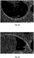
- FIGs. 5B-5C are schematic diagrams illustrating examples of displaying a marker of a bone fracture region according to some embodiments of the present disclosure.
- FIG. 5B shows a stretched CPR image of a rib.
- the rib is on the right side of the human body and is the third rid along the direction from the head to the feet.
- a marker of rectangle frame 501 may be displayed in the CRP image to mark the bone fracture region of the rib.
- FIG. 5C shows a stretched CPR image of a rib.
- the rib is on the left side of the human body and is the eighth rid along the direction from the head to the feet.
- a marker of rectangle frame 502 may be displayed in the CRP image to mark the bone fracture region of the rib.
- the processing device 140 may display the original image, the target image, and the reconstruction image (e.g., the MPR image, the CPR image, the 3D rendering image, etc.) of the rib at the same time.
- the reconstruction image e.g., the MPR image, the CPR image, the 3D rendering image, etc.
- doctors may analyze a plurality of medical images and use their own experience to detect bone fractures.
- the present disclosure provides methods and/or systems for fracture detection to achieve automated detection using a fracture detection model without or with minimal reliance on a doctor's experience in specific cases, which may reduce manual operations and the time to proform the fracture detection, improve the efficiency and the accuracy of fracture detection, and/or obtain a more objective fracture detection result.
- the processing device 140 may detect two or more bone fracture regions of the one or more ribs in a medical image using the fracture detection model described in the present disclosure. For example, the processing device 140 may detect two or more bone fracture regions in different ribs in a medical image using the fracture detection model. As another example, the processing device 140 may detect two or more bone fracture regions in a same rib in a medical image using the fracture detection model.
- the processing device 140 may combine the detected fracture regions whose distance between each other that is equal to the distance threshold.
- the processing device 140 may detect a bone fracture region of the one or more ribs in the medical image using the fracture detection model.
- FIG. 7A is a flowchart illustrating an exemplary process for generating a CPR image according to some embodiments of the present disclosure.
- the process 700 may be implemented in the computer aided diagnosis system 100 illustrated in FIG. 1 .
- the process 700 may be stored in a storage medium (e.g., the storage device 150, or the storage 220 of the processing device 140) in the form of instructions, and can be invoked and/or executed by the processing device 140 (e.g., the processor 210 of the processing device 140, or one or more modules in the processing device 140 illustrated in FIG. 4 ).
- the operations of the illustrated process 700 presented below are intended to be illustrative. In some embodiments, the process 700 may be accomplished with one or more additional operations not described, and/or without one or more of the operations discussed. Additionally, the order in which the operations of the process 700 as illustrated in FIG. 7 and described below is not intended to be limiting.
- a process for automatically extracting a centerline of ribs may be used to generate the CPR image.
- the processing device 140 may extract a centerline of the ribs based on the target image or the medical image.
- the series of 2D original images may be stacked together to generate volume data of the ROI including the ribs. Doctors need to manually determine a plurality of points in the ribs in the volume data.
- the processing device 140 may determine the centerline based on the manually determined points.
- a process for automatically extracting a centerline of ribs may be used to generate the CPR image.
- the processing device 140 may use any existing technology for automated centerline extraction, such as a topological thinning algorithm, an algorithm based on distance transform and shortest path, a tracking-based algorithm, or the like, or any combination thereof.
- border pixels (or voxels) of the bone in the target image or the medical image may be symmetrically peeled conforming to topology principles in an iterative process until no pixel (or voxel) reduction occurs.
- the topological thinning algorithm may generate a one-pixel (or voxel) wide centerline region of the bone directly with exact centrality. Border points whose deletion do not induce any topological property change may be peeled iteratively.
- an initial point and direction may be determined in the target image or the medical image.
- the centerline path may grow in a search direction iteratively based on local properties, such as the spatial continuity of the bone's centerline points, curvature, diameter, and intensity of the bone.
- an initial point may be determined in the target image or the medical image.
- the distance transform may be performed on the target image or the medical image by determining a distance between each pixel (or voxel) in the target image or the medical image and the initial point. Pixels (or voxels) with a same distance away from the initial point may be included a same group. In each group, pixels (or voxels) with a shortest distance away from the surface of the bone and a largest pixel value (or voxel value) may be identified. The centerline of the bone may be determined by connecting the identified pixels (or voxels).
- the processing device 140 may generate a curved planar reconstruction (CPR) image based on the centerline of the ribs.
- CPR curved planar reconstruction
- the processing device 140 may generate a stretched CPR image of the rib.
- the rib may be displayed from a view parallel to the rib (e.g., along the extending direction of the rib), which may make doctors easily observe the entire and real morphology of the rib in the CPR image.
- FIG. 7B shows a stretched CPR image of a rib.
- the rib is on the right side of the human body and is the third rid along the direction from head to feet.
- FIG. 7C shows a stretched CPR image of a rib.
- the rib is on the left side of the human body and is the eighth rid along the direction from head to feet.
- FIG. 8 is a schematic diagram illustrating an example of a management list according to some embodiments of the present disclosure.
- the processing device 140 may generate a management list to manage images (e.g., the original images, the target images, and/or the reconstruction images) of the ribs, the fracture detection result, one or more bone masks of the ribs, and/or the result of centerline extraction.
- images e.g., the original images, the target images, and/or the reconstruction images
- the fracture detection result e.g., the fracture detection result, one or more bone masks of the ribs, and/or the result of centerline extraction.
- the management list may include a menu including a number of at least one rib, a name of at least one image of the ribs, a name of other kinds of bones, and function options.
- the list 800 is presented on an interactive interface, displayed in the processing device 140 through, for example, the I/O 230, of a part of a management list.
- the numbering of several ribs are listed in column 810.
- the ribs are divided into two sections by the spine, e.g., a right section located on the right side of the human body and a left section located on the left side of the human body.
- the ribs in each section are numbered from 1 and increase.
- the rib that is in the right section and is closest to the head has a number of R1.
- the rib that is in the left section and is closest to the head has a number of L1.
- “Base” refers to the bones (e.g., the spine) other than the ribs in the images of ribs.
- function options are listed in columns 820-840.
- Options of the transparent of the displayed ribs are listed in the column 820.
- Options of the color of the displayed ribs are listed in the column 830.
- Options as to whether to display a specific rib are listed in the column 840.
- the sign 841 indicates that the bones (e.g., the spine) other than the ribs are not displayed in all of or a portion of the images of ribs.
- the sign 842 indicates that the rib L1 is displayed in the images of ribs.
- images e.g., the original image, the target image, and the reconstruction image
- the rib in the images may be marked.
- the fracture detection result may be displayed in the images of the rib.
- a stretched CPR image and/or one or more MPR images including the rib L1 may be displayed.
- the fracture detection result may be displayed in the stretched CPR image and/or one or more MPR images including the rib L1.
- the computer aided diagnosis system 100 may enable doctors to observe the rib structure and/or the bone fracture of the ribs from different angles of view through different images of ribs at the same time.
- the processing device 140 may locate the images of ribs into a same spatial coordinate system so that locations in the images of ribs have a corresponding relationship.
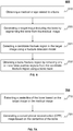
- the processing device 110 may receive an instruction of selecting, for display, a first location in a first medical image of multiple medical images.
- the processing device 110 may simultaneously display the first medical image, or a portion thereof, including the selected first location and a second medical image, or a portion thereof, of the multiple medical images.
- the second medical image may include a second location corresponding to the first location.
- the processing device 110 may display a marker of the second location in the second medical image.
- FIGs. 9A-9D are images corresponding to different angles of view of an ROI including ribs. If a doctor selects location 901 (e.g., the doctor puts a cursor in location 901) in FIG. 9A , locations 902-904 in FIGs. 9B-9C corresponding to location 901 may be marked at the same time (e.g., the cursors in FIGs. 9B-9C may be automatically located in locations 902-904 at the same time).
- location 901 e.g., the doctor puts a cursor in location 901
- locations 902-904 in FIGs. 9B-9C corresponding to location 901 may be marked at the same time (e.g., the cursors in FIGs. 9B-9C may be automatically located in locations 902-904 at the same time).
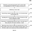
- FIG. 10 is a flowchart illustrating an exemplary process 1000 for detecting bone fracture according to some embodiments of the present disclosure.
- the fracture detection model is a 2D fracture detection model.
- the processing device 140 may obtain computed tomography (CT) data of ribs corresponding to a plurality of slices of a patient (e.g., a series of 2D original images taken at successive slices of the patient).
- CT computed tomography
- the processing device 140 may obtain a bone mask (e.g., a 3D bone mask) of the ribs.
- a bone mask e.g., a 3D bone mask
- the processing device 140 may determine, based on the bone mask, the CT data (e.g., the 2D original images) corresponding to the slices that include the ribs.
- the CT data e.g., the 2D original images
- the processing device 140 may extract the rib data (e.g., the target images) from the CT data corresponding to the slices that include the ribs, and input the rib data into a two-dimensional (2D) fracture detection model.
- the rib data e.g., the target images
- the processing device 140 may detect a candidate bone fracture region in the rib data corresponding to each slice that includes the ribs using the 2D fracture detection model.
- the processing device 140 may determine whether the fracture detection using the 2D fracture detection model is completed. In response to a determination that the fracture detection using the 2D fracture detection model is not completed, the process 1000 may proceed to operation 1050. In response to a determination that the fracture detection using the 2D fracture detection model is completed, the process 1000 may proceed to operation 1070.
- the processing device 140 may obtain a bone fracture region by removing one or more false positive regions from the candidate fracture region using the bone mask.
- the processing device 140 may combine the detected bone fracture regions corresponding to at least two of the slices, and display a fracture detection result.
- a distance between the detected bone fracture regions that are combined may be less than or equal to a predetermined distance.
- operation 1040 may be omitted.
- the processing device 140 may detect a candidate bone fracture region in the CT data (e.g., the 2D original images) corresponding to the slices that include the ribs.
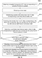
- FIG. 11 is a flowchart illustrating an exemplary process 1100 for detecting bone fracture according to some embodiments of the present disclosure.
- the fracture detection model is a 3D fracture detection model.
- the processing device 140 may obtain computed tomography (CT) volume data corresponding to an ROI of a patient including ribs.
- CT computed tomography
- the processing device 140 may obtain a bone mask (e.g., a 3D bone mask) of the ribs.
- a bone mask e.g., a 3D bone mask
- the processing device 140 may determine, based on the bone mask, the rib volume data (e.g., corresponding to a volume smaller than that corresponding to the CT volume data) including the ribs.
- the processing device 140 may input the rib volume data into a three-dimensional (3D) fracture detection model.
- the processing device 140 may detect a candidate bone fracture region in the rib volume data using the 3D fracture detection model.
- the processing device 140 may obtain a bone fracture region by removing one or more false positive regions from the candidate fracture region using the bone mask, and display a fracture detection result.
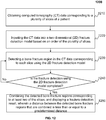
- FIG. 12 is a flowchart illustrating an exemplary process 1200 for detecting bone fracture according to some embodiments of the present disclosure.
- the fracture detection model is a 2D fracture detection model, and the fracture detection model has functions of fracture detection and bone segmentation.
- the processing device 140 may obtain computed tomography (CT) data of ribs corresponding to a plurality of slices of a patient (e.g., a series of 2D original images taken at successive slices of the patient).
- CT computed tomography
- the processing device 140 may input the CT data into a two-dimensional (2D) fracture detection model based on an order of the plurality of slices.
- the processing device 140 may detect a bone fracture region in the CT data corresponding to each slice that includes the ribs using the 2D fracture detection model.
- the processing device 140 may determine whether the fracture detection using the 2D fracture detection model is completed. In response to a determination that the fracture detection using the 2D fracture detection model is not completed, the process 1200 may proceed to operation 1230. In response to a determination that the fracture detection using the 2D fracture detection model is completed, the process 1200 may proceed to operation 1250.
- the processing device 140 may combine the detected bone fracture regions corresponding to at least two of the slices, and display a fracture detection result.
- a distance between the detected bone fracture regions that are combined may be less than or equal to a predetermined distance.
- the present invention can also be embodied as follows:
Landscapes
- Engineering & Computer Science (AREA)
- Health & Medical Sciences (AREA)
- Medical Informatics (AREA)
- Theoretical Computer Science (AREA)
- Physics & Mathematics (AREA)
- General Health & Medical Sciences (AREA)
- General Physics & Mathematics (AREA)
- Radiology & Medical Imaging (AREA)
- Nuclear Medicine, Radiotherapy & Molecular Imaging (AREA)
- Public Health (AREA)
- Computer Vision & Pattern Recognition (AREA)
- Epidemiology (AREA)
- Primary Health Care (AREA)
- Quality & Reliability (AREA)
- Computing Systems (AREA)
- Data Mining & Analysis (AREA)
- Biomedical Technology (AREA)
- Software Systems (AREA)
- General Engineering & Computer Science (AREA)
- Evolutionary Computation (AREA)
- Artificial Intelligence (AREA)
- Geometry (AREA)
- Mathematical Physics (AREA)
- Computer Graphics (AREA)
- Databases & Information Systems (AREA)
- Pathology (AREA)
- Apparatus For Radiation Diagnosis (AREA)
- Image Analysis (AREA)
Abstract
Description
- This application claims priority to Chinese Patent Application No.
201810322914.8 filed on April 11, 2018 - The present disclosure generally relates to medical imaging, and in particular, to systems and methods for bone fracture detection by way of image processing.
- With the rapid development of industry and transportation, industrial injuries and injuries caused by traffic accidents, such as bone fracture, are increasing. Fracture detection and diagnosis play an important role in current medical treatment. In the existing medical treatment, doctors usually use, for example, computed tomography (CT) to detect the bone fracture. During the process of fracture detection, doctors need to observe and analyze a plurality of CT images to identify bone fracture based on the experience of the doctor. For example, in the fracture detection of ribs, due to the complicated anatomical shape of the ribs, doctors need to observe and analyze a plurality of CT images to identify bone fracture in each rib. Some bone fractures exist in positions of the ribs that are not easily observed. In this case, the doctors need to study and analyze a plurality of CT images, which rely on the experience of the doctors, and make the fracture detection laborious and subjective. Therefore, it is desirable to provide systems and/or methods for automated bone fracture detection to improve the efficiency and the accuracy of bone fracture detection.
- According to a first aspect of the present disclosure, a computer aided diagnosis system for bone fracture detection may include one or more storage devices and one or more processors configured to communicate with the one or more storage devices. The one or more storage devices may include a set of instructions. When the one or more processors executing the set of instructions, the one or more processors may be directed to perform one or more of the following operations. The one or more processors may obtain one or more medical images related to one or more bones. The one or more processors may obtain a fracture detection model generated based on a machine learning model. The one or more processors may detect, for at least one of the one or more medical images, one or more bone fracture regions of the one or more bones in the medical image using the fracture detection model.
- In some embodiments, the fracture detection model may be obtained by performing operations including: obtaining training images in which bone fractures are marked; and determining the fracture detection model by training a preliminary model using the training images.
- In some embodiments, to detect the one or more bone fracture regions of the one or more bones in the medical image using the fracture detection model, the one or more processors may detect one or more candidate fracture regions in the medical image using the fracture detection model. The one or more processors may obtain the one or more bone fracture regions by removing one or more false positive regions from the one or more candidate fracture regions using a bone mask related to the one or more bones.
- In some embodiments, the one or more processors may display a marker of the one or more bone fracture regions in the at least one of the one or more medical images.
- In some embodiments, the one or more processors may determine a type of bone fracture in the one or more bone fracture regions using the fracture detection model.
- In some embodiments, the one or more medical images may include multiple medical images taken at different slices of the one or more bones. The one or more processors may determine whether there are at least two of the multiple medical images in each of which the one or more bone fracture regions are detected. The one or more processors may determine a distance between the detected bone fracture regions in the at least two of the multiple medical images in response to a determination that there are at least two of the multiple medical images in each of which the one or more bone fracture regions are detected. The one or more processors may determine whether the distance is less than a distance threshold. The one or more processors may combine the detected bone fracture regions in the at least two of the multiple medical images in response to a determination that the distance is less than the distance threshold. The detected bone fracture regions in the at least two of the multiple medical images may be deemed to relate to a same bone fracture.
- In some embodiments, the one or more processors may reconstruct one or more bone images based on the one or more detected bone fracture regions or the combined bone fracture region. The one or more processors may display a marker of the one or more detected bone fracture regions or the combined bone fracture region in the one or more bone images.
- In some embodiments, the one or more bone images may include at least one of a curved planar reconstruction (CPR) image, a multiplanar reconstruction (MPR) image, and a three-dimensional (3D) rendering image.
- In some embodiments, to reconstruct the CPR image, the one or more processors may extract a centerline of at least one of the one or more bones based on the one or more medical images. The one or more processors may generate a stretched CPR image based on the centerline of the bone.
- In some embodiments, the one or more processors may display a management list for managing at least one of one or more bone masks related to the one or more bones and information related to the one or more detected bone fracture regions.
- In some embodiments, the one or more processors may receive an instruction related to selecting at least one of the one or more bones. The instruction may be generated through the management list or the 3D rendering image. The one or more processors may display at least one of the stretched CPR image and one or more MPR images related to the at least one selected bone based on the instruction.
- In some embodiments, the fracture detection model may be obtained based on a convolutional neural network (CNN).
- In some embodiments, the one or more medical images may include multiple medical images. The one or more processors may receive an instruction of selecting, for display, a first location in a first medical image of the one or more medical images. The one or more processors may simultaneously display the first medical image, or a portion thereof, including the selected first location and a second medical image, or a portion thereof, of the one or more medical image. The second medical image may include a second location corresponding to the first location.
- In some embodiments, the displaying of the second medical image, or a portion thereof, may include displaying a marker of the second location.
- In some embodiments, the one or more processors may generate, for at least one of the one or more medical images, a target image including the one or more bones by segmenting the one or more bones from the medical image.
- According to another aspect of the present disclosure, a computer aided diagnosis method for bone fracture detection may include one or more of the following operations. One or more processors may obtain one or more medical images related to one or more bones. The one or more processors may obtain a fracture detection model generated based on a machine learning model. The one or more processors may detect, for at least one of the one or more medical images, one or more bone fracture regions of the one or more bones in the medical image using the fracture detection model.
- According to yet another aspect of the present disclosure, a computer aided diagnosis system for bone fracture detection may include an obtaining module configured to obtain one or more medical images related to one or more bones. The system may also include a processing module configured to obtain a fracture detection model generated based on a machine learning model and detect, for at least one of the one or more medical images, one or more bone fracture regions of the one or more bones in the medical image using the fracture detection model.
- According to yet another aspect of the present disclosure, a non-transitory computer readable medium may comprise at least one set of instructions for bone fracture detection. The at least one set of instructions may be executed by one or more processors of a computer server. The one or more processors may obtain one or more medical images related to one or more bones. The one or more processors may obtain a fracture detection model generated based on a machine learning model. The one or more processors may detect, for at least one of the one or more medical images, one or more bone fracture regions of the one or more bones in the medical image using the fracture detection model.
- The present disclosure is further described in terms of exemplary embodiments. These exemplary embodiments are described in detail with reference to the drawings. These embodiments are non-limiting exemplary embodiments, in which like reference numerals represent similar structures throughout the several views of the drawings, and wherein:
-
FIG. 1 is a schematic diagram illustrating an exemplary computer aided diagnosis according to some embodiments of the present disclosure; -
FIG. 2 is a schematic diagram illustrating exemplary hardware and/or software components of a computing device according to some embodiments of the present disclosure; -
FIG. 3 is a schematic diagram illustrating exemplary hardware and/or software components of a mobile device according to some embodiments of the present disclosure; -
FIG. 4 is a schematic block diagram illustrating an exemplary processing device according to some embodiments of the present disclosure; -
FIG. 5A is a flowchart illustrating an exemplary process for detecting bone fracture according to some embodiments of the present disclosure; -
FIGs. 5B-5C are schematic diagrams illustrating examples of displaying a marker of a bone fracture region according to some embodiments of the present disclosure; -
FIG. 6 is a flowchart illustrating an exemplary process for detecting bone fracture according to some embodiments of the present disclosure; -
FIG. 7A is a flowchart illustrating an exemplary process for generating a curved planar reconstruction (CPR) image according to some embodiments of the present disclosure; -
FIGs. 7B-7C are schematic diagrams illustrating examples of stretched CPR images of a rib according to some embodiments of the present disclosure; -
FIG. 8 is a schematic diagram illustrating an example of a management list according to some embodiments of the present disclosure; -
FIGs. 9A-9D are schematic diagrams illustrating examples of different images of ribs according to some embodiments of the present disclosure; and -
FIGs. 10-12 are flowcharts illustrating exemplary processes for detecting bone fracture according to some embodiments of the present disclosure. - These and other features, and characteristics of the present disclosure, as well as the methods of operation and functions of the related elements of structure and the combination of parts and economies of manufacture, may become more apparent upon consideration of the following description with reference to the accompanying drawings, all of which form a part of this disclosure. It is to be expressly understood, however, that the drawings are for the purpose of illustration and description only and are not intended to limit the scope of the present disclosure. It is understood that the drawings are not to scale.
- An aspect of the present disclosure relates to systems and methods for automated bone fracture detection by way of image processing. In the systems and methods for automated bone fracture detection in the present disclosure, bone fractures in medical images may be automatically detected using a bone fracture detection model. The fracture detection model may be developed on the basis of a machine learning model. In existing processes for fracture detection, doctors may need to analyze a plurality of medical images and use their own experience to detect bone fractures represented in the images. Compared with the existing processes for fracture detection, the methods and/or systems for fracture detection in the present disclosure may achieve automated detection using a fracture detection model, which may reduce manual operations and the time to perform the fracture detection, improve the efficiency and/or the accuracy of the fracture detection, and/or obtain a more objective fracture detection result.
- In some embodiments of the present disclosure, a marker of the detected bone fracture region may be displayed in an original image generated based on raw data obtained during a scan of the bone (e.g., a rib), a curved planar reconstruction (CPR) image (e.g., a stretched CPR image), a multiplanar reconstruction (MPR) image, a three-dimensional (3D) rendering image, or the like. During the reconstruction of the stretched CPR image, a centerline of the bone may be automatically extracted based on image data (e.g., the original images of different slices of the bone), instead of being manually determined. The stretched CPR image may be reconstructed based on the centerline. In the stretched CPR image of a rib, the rib may be displayed from a view parallel to the rib (e.g., along the extending direction of the rib), which may make it relatively easy for doctors to observe the entire and real morphology of the rib in the CPR image.
-
FIG. 1 is a schematic diagram illustrating an exemplary computer aideddiagnosis system 100 according to some embodiments of the present disclosure. As illustrated, the computer aideddiagnosis system 100 may include animaging device 110, anetwork 120, auser terminal 130, aprocessing device 140, and astorage device 150. The components of the computer aideddiagnosis system 100 may be connected in one or more of various ways. Mere by way of example, as illustrated inFIG. 1 , theimaging device 110 may be connected to theprocessing device 140 through thenetwork 120. As another example, theimaging device 110 may be connected to theprocessing device 140 directly (as indicated by the bi-directional arrow in dotted lines linking theimaging device 110 and the processing device 140). As a further example, thestorage device 150 may be connected to theprocessing device 140 directly or through thenetwork 120. As still a further example, a terminal device (e.g., 131, 132, 133, etc.) may be connected to theprocessing device 140 directly (as indicated by the bi-directional arrow in dotted lines linking theuser terminal 130 and the processing device 140) or through thenetwork 120. - The
imaging device 110 may scan an object located within its detection region and generate a plurality of data relating to the object. In the present disclosure, "subject" and "object" are used interchangeably. Mere by way of example, the object may include a patient, a man-made object, etc. As another example, the object may include a specific portion, organ, and/or tissue of a patient. For example, the object may include head, brain, neck, body, shoulder, arm, thorax, cardiac, stomach, blood vessel, soft tissue, knee, feet, bones, or the like, or any combination thereof. - In some embodiments, the
imaging device 110 may include a magnetic resonance imaging (MRI) device, a positron emission tomography (PET) device, a computed tomography (CT) device, a radiography device, or the like, or any combination thereof. - The
network 120 may include any suitable network that can facilitate the exchange of information and/or data for the computer aideddiagnosis system 100. In some embodiments, one or more components of the computer aided diagnosis system 100 (e.g., theimaging device 110, theuser terminal 130, theprocessing device 140, or the storage device 150) may communicate information and/or data with one or more other components of the computer aideddiagnosis system 100 via thenetwork 120. For example, theprocessing device 140 may obtain raw data from theimaging device 110 via thenetwork 120. In some embodiments, thenetwork 120 may be any type of wired or wireless network, or a combination thereof. Thenetwork 120 may be and/or include a public network (e.g., the Internet), a private network (e.g., a local area network (LAN), a wide area network (WAN)), etc.), a wired network (e.g., an Ethernet network), a wireless network (e.g., an 802.11 network, a Wi-Fi network, etc.), a cellular network (e.g., a Long Term Evolution (LTE) network), a frame relay network, a virtual private network ("VPN"), a satellite network, a telephone network, routers, hubs, switches, server computers, and/or any combination thereof. Merely by way of example, thenetwork 120 may include a cable network, a wireline network, a fiber-optic network, a telecommunications network, an intranet, a wireless local area network (WLAN), a metropolitan area network (MAN), a public telephone switched network (PSTN), a Bluetooth™ network, a ZigBee™ network, a near field communication (NFC) network, or the like, or any combination thereof. In some embodiments, thenetwork 120 may include one or more network access points. For example, thenetwork 120 may include wired and/or wireless network access points such as base stations and/or internet exchange points through which one or more components of the computer aideddiagnosis system 100 may be connected to thenetwork 120 to exchange data and/or information. - The
user terminal 130 may include amobile device 131, atablet computer 132, alaptop computer 133, or the like, or any combination thereof. In some embodiments, themobile device 131 may include a smart home device, a wearable device, a smart mobile device, a virtual reality device, an augmented reality device, or the like, or any combination thereof. In some embodiments, the smart home device may include a smart lighting device, a control device of an intelligent electrical apparatus, a smart monitoring device, a smart television, a smart video camera, an interphone, or the like, or any combination thereof. In some embodiments, the wearable device may include a smart bracelet, smart footgear, a pair of smart glasses, a smart helmet, a smart watch, smart clothing, a smart backpack, a smart accessory, or the like, or any combination thereof. In some embodiments, the smart mobile device may include a smartphone, a personal digital assistant (PDA), a gaming device, a navigation device, a point of sale (POS) device, or the like, or any combination thereof. In some embodiments, the virtual reality device and/or the augmented reality device may include a virtual reality helmet, a virtual reality glass, a virtual reality patch, an augmented reality helmet, an augmented reality glass, an augmented reality patch, or the like, or any combination thereof. For example, the virtual reality device and/or the augmented reality device may include a Google™ Glass, an Oculus Rift, a Hololens, a Gear VR, etc. In some embodiments, theuser terminal 130 may remotely operate theimaging device 110 and/or theprocessing device 140. In some embodiments, theuser terminal 130 may operate theimaging device 110 and/or theprocessing device 140 via a wireless connection. In some embodiments, theuser terminal 130 may receive information and/or instructions inputted by a user, and send the received information and/or instructions to theimaging device 110 or to theprocessing device 140 via thenetwork 120. In some embodiments, theuser terminal 130 may receive data and/or information from theprocessing device 140. In some embodiments, theuser terminal 130 may be part of theprocessing device 140. In some embodiments, theuser terminal 130 may be omitted. - The
processing device 140 may process data and/or information obtained from theimaging device 110, theuser terminal 130, and/or thestorage device 150. For example, theprocessing device 140 may detect a bone fracture in one or more medical images by processing the one or more medical images. In some embodiments, theprocessing device 140 may be a single server or a server group. The server group may be centralized or distributed. In some embodiments, theprocessing device 140 may be local or remote. For example, theprocessing device 140 may access information and/or data stored in or acquired by theimaging device 110, theuser terminal 130, and/or thestorage device 150 via thenetwork 120. As another example, theprocessing device 140 may be directly connected to theimaging device 110, theuser terminal 130, and/or thestorage device 150 to access stored or acquired information and/or data. In some embodiments, theprocessing device 140 may be implemented on a cloud platform. Merely by way of example, the cloud platform may include a private cloud, a public cloud, a hybrid cloud, a community cloud, a distributed cloud, an inter-cloud, a multi-cloud, or the like, or any combination thereof. In some embodiments, theprocessing device 140 may be implemented on acomputing device 200 having one or more components illustrated inFIG. 2 in the present disclosure. - The
storage device 150 may store data and/or instructions. In some embodiments, thestorage device 150 may store data obtained from theimaging device 110, theuser terminal 130 and/or theprocessing device 140. For example, thestorage device 150 may store one or more medical images generated by theprocessing device 140 based on raw data obtained from theimaging device 110. In some embodiments, thestorage device 150 may store data and/or instructions that theprocessing device 140 may execute or use to perform exemplary methods described in the present disclosure. For example, thestorage device 150 may store instructions that theprocessing device 140 may execute to detect bone fractures in one or more medical images by processing the one or more medical images. In some embodiments, thestorage device 150 may include a mass storage device, a removable storage device, a volatile read-and-write memory, a read-only memory (ROM), or the like, or any combination thereof. Exemplary mass storage may include a magnetic disk, an optical disk, a solid-state drive, etc. Exemplary removable storage may include a flash drive, a floppy disk, an optical disk, a memory card, a zip disk, a magnetic tape, etc. Exemplary volatile read-and-write memory may include a random access memory (RAM). Exemplary RAM may include a dynamic RAM (DRAM), a double date rate synchronous dynamic RAM (DDR SDRAM), a static RAM (SRAM), a thyristor RAM (T-RAM), and a zero-capacitor RAM (Z-RAM), etc. Exemplary ROM may include a mask ROM (MROM), a programmable ROM (PROM), an erasable programmable ROM (PEROM), an electrically erasable programmable ROM (EEPROM), a compact disk ROM (CD-ROM), and a digital versatile disk ROM, etc. In some embodiments, thestorage device 150 may be implemented on a cloud platform. Merely by way of example, the cloud platform may include a private cloud, a public cloud, a hybrid cloud, a community cloud, a distributed cloud, an inter-cloud, a multi-cloud, or the like, or any combination thereof. - In some embodiments, the
storage device 150 may be connected to thenetwork 120 to communicate with one or more components of the computer aided diagnosis system 100 (e.g., theimaging device 110, theprocessing device 140, theuser terminal 130, etc.). One or more components of the computer aideddiagnosis system 100 may access the data or instructions stored in thestorage device 150 via thenetwork 120. In some embodiments, thestorage device 150 may be directly connected to or communicate with one or more components of the computer aided diagnosis system 100 (e.g., theimaging device 110, theprocessing device 140, theuser terminal 130, etc.). In some embodiments, thestorage device 150 may be part of theprocessing device 140. -
FIG. 2 is a schematic diagram illustrating exemplary hardware and/or software components of a computing device on which theprocessing device 140 may be implemented according to some embodiments of the present disclosure. As illustrated inFIG. 2 , thecomputing device 200 may include aprocessor 210, astorage 220, an input/output (I/O) 230, and acommunication port 240. - The
processor 210 may execute computer instructions (program code) and perform functions of the processing device140 in accordance with techniques described herein. The computer instructions may include routines, programs, objects, components, signals, data structures, procedures, modules, and functions, which perform particular functions described herein. For example, theprocessor 210 may detect bone fractures in one or more medical images by processing the one or more medical images. In some embodiments, theprocessor 210 may include a microcontroller, a microprocessor, a reduced instruction set computer (RISC), an application specific integrated circuits (ASICs), an application-specific instruction-set processor (ASIP), a central processing unit (CPU), a graphics processing unit (GPU), a physics processing unit (PPU), a microcontroller unit, a digital signal processor (DSP), a field programmable gate array (FPGA), an advanced RISC machine (ARM), a programmable logic device (PLD), any circuit or processor capable of executing one or more functions, or the like, or any combinations thereof. - Merely for illustration purposes, only one processor is described in the
computing device 200. However, it should be noted that thecomputing device 200 in the present disclosure may also include multiple processors, and thus operations of a method that are performed by one processor as described in the present disclosure may also be jointly or separately performed by the multiple processors. For example, if in the present disclosure the processor of thecomputing device 200 executes both operations A and B, it should be understood that operations A and step B may also be performed by two different processors jointly or separately in the computing device 200 (e.g., a first processor executes operation A and a second processor executes operation B, or the first and second processors jointly execute operations A and B). - The
storage 220 may store data/information obtained from theimaging device 110, theuser terminal 130, thestorage device 150, or any other component of the computer aideddiagnosis system 100. In some embodiments, thestorage 220 may include a mass storage device, a removable storage device, a volatile read-and-write memory, a read-only memory (ROM), or the like, or any combination thereof. For example, the mass storage device may include a magnetic disk, an optical disk, a solid-state drive, etc. The removable storage device may include a flash drive, a floppy disk, an optical disk, a memory card, a zip disk, a magnetic tape, etc. The volatile read-and-write memory may include a random access memory (RAM). The RAM may include a dynamic RAM (DRAM), a double date rate synchronous dynamic RAM (DDR SDRAM), a static RAM (SRAM), a thyristor RAM (T-RAM), and a zero-capacitor RAM (Z-RAM), etc. The ROM may include a mask ROM (MROM), a programmable ROM (PROM), an erasable programmable ROM (PEROM), an electrically erasable programmable ROM (EEPROM), a compact disk ROM (CD-ROM), and a digital versatile disk ROM, etc. In some embodiments, thestorage 220 may store one or more programs and/or instructions to perform exemplary methods described in the present disclosure. For example, thestorage 220 may store a program for theprocessing device 140 to detect bone fractures in one or more medical images by processing the one or more medical images. - The I/
O 230 may input or output signals, data, or information. In some embodiments, the I/O 230 may enable a user interaction with theprocessing device 140. In some embodiments, the I/O 230 may include an input device and an output device. Exemplary input devices may include a keyboard, a mouse, a touch screen, a microphone, a trackball, or the like, or a combination thereof. Exemplary output devices may include a display device, a loudspeaker, a printer, a projector, or the like, or a combination thereof. Exemplary display devices may include a liquid crystal display (LCD), a light-emitting diode (LED)-based display, a flat panel display, a curved screen, a television device, a cathode ray tube (CRT), or the like, or a combination thereof. - Merely by way of example, a user (e.g., an operator) of the
processing device 140 may input data related to an object (e.g., a patient) that is being/to be imaged/scanned through the I/O 230. The data related to the object may include identification information (e.g., the name, age, gender, medical history, contract information, physical examination result, etc.) and/or the test information including the nature of the scan that must be performed. The user may also input parameters needed for the operation of theimaging device 110. For example, for CT imaging, the user may input a scan protocol including a scanning time, a region of interest (ROI), a rotation speed of theimaging device 110, a voltage/current intensity, etc. The I/O may also display medical images. - The
communication port 240 may be connected to a network (e.g., the network 120) to facilitate data communications. Thecommunication port 240 may establish connections between the processing device140 and theimaging device 110, theuser terminal 130, or thestorage device 150. The connection may be a wired connection, a wireless connection, or a combination of both that enables data transmission and reception. The wired connection may include an electrical cable, an optical cable, a telephone wire, or the like, or any combination thereof. The wireless connection may include Bluetooth, Wi-Fi, WiMax, WLAN, ZigBee, mobile network (e.g., 3G, 4G, 5G, etc.), or the like, or a combination thereof. In some embodiments, thecommunication port 240 may be a standardized communication port, such as RS232, RS485, etc. In some embodiments, thecommunication port 240 may be a specially designed communication port. For example, thecommunication port 240 may be designed in accordance with the digital imaging and communications in medicine (DICOM) protocol. -
FIG. 3 is a schematic diagram illustrating exemplary hardware and/or software components of a mobile device on which theuser terminal 130 may be implemented according to some embodiments of the present disclosure. As illustrated inFIG. 3 , themobile device 300 may include acommunication platform 310, adisplay 320, a graphics processing unit (GPU) 330, a central processing unit(CPU) 340, an I/O 350, amemory 360, and astorage 390. In some embodiments, any other suitable component, including but not limited to a system bus or a controller (not shown), may also be included in themobile device 300. In some embodiments, a mobile operating system 370 (e.g., iOS, Android, Windows Phone, etc.) and one ormore applications 380 may be loaded into thememory 360 from thestorage 390 in order to be executed by theCPU 340. Theapplications 380 may include a browser or any other suitable mobile apps for receiving and rendering information relating to image processing or other information from theprocessing device 140. User interactions with the information stream may be achieved via the I/O 350 and provided to the processing device140 and/or other components of the computer aideddiagnosis system 100 via thenetwork 120. - To implement various modules, units, and their functionalities described in the present disclosure, computer hardware platforms may be used as the hardware platform(s) for one or more of the elements described herein. The hardware elements, operating systems and programming languages of such computers are conventional in nature, and it is presumed that those skilled in the art are adequately familiar therewith to adapt those technologies to the blood pressure monitoring as described herein. A computer with user interface elements may be used to implement a personal computer (PC) or another type of work station or terminal device, although a computer may also act as a server if appropriately programmed. It is believed that those skilled in the art are familiar with the structure, programming and general operation of such computer equipment and as a result the drawings should be self-explanatory.
- For illustration purposes, the methods and/or systems for bone fracture detection in the present disclosure are described with reference to ribs as an example. It should be noted that the methods and/or systems for bone fracture detection described below are merely some examples or implementations. For persons having ordinary skills in the art, the methods and/or systems for bone fracture detection in the present disclosure may be applied to bone fracture detection of other kinds of bones, such as tibias, spine, etc.
- It should be noted that, in the present disclosure, an image, or a portion thereof (e.g., a region in the image) corresponding to an object (e.g., tissue, an organ, a tumor, etc.) may be referred to as an image, or a portion of thereof (e.g., a region) of or including the object, or the object itself. For instance, a region in an image that corresponds to or represents a bone may be described as that the region includes a bone. As another example, an image of or including a bone may be referred to a bone image, or simply bone. For brevity, that a portion of an image corresponding to or representing an object is processed (e.g., extracted, segmented, etc.) may be described as the object is processed. For instance, that a portion of an image corresponding to a bone is segmented from the rest of the image may be described as that the bone is segmented from the image.
-
FIG. 4 is a schematic block diagram illustrating an exemplary processing device according to some embodiments of the present disclosure. Theprocessing device 140 may include an obtainingmodule 410, asegmentation module 420, and aprocessing module 430. - The obtaining
module 410 may be configured to obtain a medical image related to one or more ribs. Thesegmentation module 420 may be configured to generate a target image including the one or more ribs by segmenting the one or more ribs from the medical image. Theprocessing module 430 may be configured to detect a bone fracture region of the one or more ribs in the target image using a fracture detection model. -
FIG. 5A is a flowchart illustrating an exemplary process for detecting bone fracture according to some embodiments of the present disclosure. In some embodiments, theprocess 500 may be implemented in the computer aideddiagnosis system 100 illustrated inFIG. 1 . For example, theprocess 500 may be stored in a storage medium (e.g., thestorage device 150, or thestorage 220 of the processing device 140) in the form of instructions, and can be invoked and/or executed by the processing device 140 (e.g., theprocessor 210 of theprocessing device 140, or one or more modules in theprocessing device 140 illustrated inFIG. 4 ). The operations of the illustratedprocess 500 presented below are intended to be illustrative. In some embodiments, theprocess 500 may be accomplished with one or more additional operations not described, and/or without one or more of the operations discussed. Additionally, the order in which the operations of theprocess 500 as illustrated inFIG. 5 and described below is not intended to be limiting. - In 510, the processing device 140 (e.g., the obtaining module 410) may obtain a medical image related to one or more ribs.
- In some embodiments, the medical image may include a CT image, an X-ray image, an MRI image, a PET image, a multi-modality image, or the like, or any combination thereof. Exemplary multi-modality images may include a CT-MRI image, a PET-CT image, a PET-MRI image, or the like.
- In some embodiments, the medical image may be an original image generated using raw data obtained from a scan process of an object using the
imaging device 110. For example, theimaging device 110 may be a CT scanner. During a scan process of an object (e.g., an ROI of a patient including the ribs), an X-ray generator of the CT scanner may emit X-rays. The X-rays may pass through a cross-section (e.g., a slice) of the ROI and be received by a detector of the CT scanner. The detector may transform light signals of the X-rays into electronic signals. The electronic signals may be transformed into digital signals by an analog-digital converter (ADC). The CT scanner may transmit the digital signals to theprocessing device 140. Theprocessing device 140 may process the digital signals (e.g., the raw data) to generate a CT image (e.g., the original image) of the slice. - In some embodiments, the medical image may be a reconstruction image using one or more original images (e.g., original image data). For example, the reconstruction image may be a multiplanar reconstruction (MPR) image, a curved planar reconstruction (CPR) image, a three-dimensional (3D) rendering image, or the like.
- In some embodiments, the medical image may be a two-dimensional (2D) image or a three-dimensional (3D) image.
- In 520, the processing device 140 (e.g., the segmentation module 420) may generate a target image including the one or more ribs by segmenting the one or more ribs from the medical image.
- In some embodiments, the
processing device 140 may generate a target image including all bone structures including the one or more ribs by segmenting all bone structures from the medical image. In some embodiments, theprocessing device 140 may generate a target image including only the one or more ribs by segmenting the one or more ribs from the medical image. For example, the medical image may include ribs, a spine, clavicles, and other non-bone tissues such as a lung. Theprocessing device 140 may generate a target image including the ribs, the spine, and the clavicles by segmenting the ribs, the spine, and the clavicles from the medical image. Alternatively, theprocessing device 140 may generate a target image including only the ribs by segmenting the ribs from the medical image. - In some embodiments, the target image may be generated using any existing image segmentation technology, such as a threshold-based segmentation algorithm, an edge-based segmentation algorithm, a region-based segmentation algorithm, a clustering-based algorithm, an image segmentation algorithm based on wavelet transform, an image segmentation algorithm based on mathematical morphology, and an image segmentation algorithm based on machine learning, a tracking algorithm, or the like, or any combination thereof.
- For example, the
processing device 140 may determine a bone mask including the one or more ribs based on the medical image. The bone mask may be generated by extracting the one or more ribs in the medical image using any existing segmentation technology, such as a threshold-based segmentation algorithm, an edge-based segmentation algorithm, a region-based segmentation algorithm, a clustering-based algorithm, an image segmentation algorithm based on wavelet transform, an image segmentation algorithm based on mathematical morphology, and an image segmentation algorithm based on machine learning, a tracking algorithm, or the like, or any combination thereof. In some embodiments, the bone mask may be a binary image that is a digital image that has only two possible values (e.g., 1 and 0) for each pixel or voxel. Typically, the two colors used for a binary image may be black (e.g., corresponding the value of 0) and white (e.g., corresponding the value of 1). The color (e.g., white) used for the target (e.g., the one or more ribs) in the image is the foreground color while the rest of the image is the background color (e.g., black). - The
processing device 140 may generate the target image using the bone mask. For example, theprocessing device 140 may multiply the bone mask by the medical image, that is, multiply each pixel (or voxel) value of the bone mask by the corresponding pixel (or voxel) value of the medical image. In this way, the pixel (or voxel) values of the target (e.g., the one or more ribs) in the medical image are not changed and the pixel (or voxel) values of the rest of the medical image are changed to 0, thereby generating the target image. - As another example, the
processing device 140 may obtain a bone segmentation model. Theprocessing device 140 may generate the target image by segmenting the one or more ribs from the medical image using the bone segmentation model. The bone segmentation model may be a machine learning model. Preferably, the bone segmentation model may be a deep learning model. - In 530, the processing device 140 (e.g., the processing module 430) may detect a bone fracture region of the one or more ribs in the target image using a fracture detection model. The
processing device 140 may detect the bone fracture region in the target image, which is faster than detecting the bone fracture region in the medical image. - In some embodiments, the fracture detection model may be a 2D fracture detection model applicable to 2D images. In some embodiments, the fracture detection model may be a 3D fracture detection model applicable to 3D images.
- In some embodiments, the fracture detection model may be generated based on a machine learning model. For instance, the fracture detection model may be a deep learning model. Merely by way of example, the fracture detection model may be a convolutional neural network (CNN), such as a visual geometry group network (VGG), residual neural network (resNet), etc.
- In some embodiments, the fracture detection model and the bone segmentation model may be two different models. In some embodiments, the fracture detection model may be a model having functions of the bone fracture detection and bone segmentation.
- In some embodiments, the fracture detection model may be generated by the following operations. Training images may be obtained. The training images may be images in which bone fractures are identified. In some embodiments, the fracture detection model may need to be applicable to fracture detection in different kinds of images, such as CT images, MRI images, PET images, multi-modality images, etc. In this case, the training images may include different kinds of images. In some embodiments, the fracture detection model may need to be applicable to fracture detection in a specific type of images, such as CT images. In this case, the training images may include CT images. In some embodiments, the fracture detection model may need to be applicable to fracture detection of different kinds of bones, such as ribs, tibias, etc. In this case, the training images may be images in which bone fractures are identified in different kinds of bones. In some embodiments, the fracture detection model may be required to be applicable to fracture detection of a specific kind of bones, such as ribs. In this case, the training images may be images in which bone fractures are identified in ribs. In some embodiments, the fracture detection model may need to be applicable to 2D images or 3D images. In this case, the training images may be 2D images or 3D images.
- In the training images, the bone fractures may be marked. In some embodiments, the bone fractures may be marked manually. For example, the training images may be displayed and a doctor may mark the bone fractures in the training images using, for example, a mouse or a touch screen based on, for example, diagnosis reports of the training images. In some embodiments, the bone fractures may be marked automatically. For example, the training images may be input to a computing device. The computing device may automatically mark the bone fractures based on, for example, diagnosis reports of the training images. In some embodiments, a doctor may manually modify the marker of the bone fractures automatically determined by the computing device.
- In some embodiments, a location of the bone fracture and/or a type of the bone fracture (e.g., such as osteophytes, displaced fractures, non-displaced fractures, abnormal cortical bones, occult fractures, etc.) may be marked. The location of the bone fracture may be marked in any form. For example, the location of bone fracture may be included in a frame (e.g., a rectangle frame, a circle frame, etc.). As another example, the location of bone fracture may be highlighted. As still another example, the location of bone fracture may be filled with different colors, etc.
- In some embodiments, if the fracture detection model having functions of bone segmentation and fracture detection is desired, the region belonging to ribs may also be marked in the training images. For example, pixels (or voxels) of cortical bones and cancellous bones of ribs may be marked in the training images.
- The fracture detection model may be generated by training a preliminary model using the training images.
- In some embodiments, the fracture detection model may be generated by the
processing device 140 or an external device communicating with the computer aideddiagnosis system 100. In some embodiment, theprocessing device 140 may generate the fracture detection model in advance and store the fracture detection model in a storage medium (e.g., thestorage device 150, thestorage 220 of the processing device 140). When detecting the bone fracture region, theprocessing device 140 may obtain the fracture detection model from the storage medium. In some embodiments, the external device may generate the fracture detection model in advance and store the fracture detection model locally or in the storage medium (e.g., thestorage device 150, thestorage 220 of the processing device 140) of the computer aideddiagnosis system 100. When detecting the bone fracture region, theprocessing device 140 may obtain the fracture detection model from the storage medium of the computer aideddiagnosis system 100 or the external device. - In some embodiments, the
processing device 140 may input the target image into the fracture detection model. The fracture detection model may output a fracture detection result including a determination as to whether there is a bone fracture in the target image, a location of a bone fracture region in the target image, a type of bone fracture in the bone fracture region, or the like, or any combination thereof. In some embodiments, the processing device 140 (e.g., the processing module 430) may display the fracture detection result in the target image and/or the medical image through, for example, the I/O 230 of theprocessing device 140. For example, theprocessing device 140 may display a text indicating that there is no bone fracture. As another example, theprocessing device 140 may display a marker of the detected bone fracture region. The marker of the detected bone fracture region may include a frame (e.g., a rectangle frame, a circle frame, etc.), a highlight, filling with different colors, a label, a file identifier, or the like, or any combination thereof. As still another example, theprocessing device 140 may display a text indicating the type of bone fracture in the bone fracture region. - In some embodiments,
operation 530 may be performed based onoperations FIG. 6 showing anexemplary process 600 for detecting bone fracture according to some embodiments of the present disclosure. - In 531, the processing device 140 (e.g., the processing module 430) may detect a candidate fracture region in the target image using the fracture detection model.
- In 532, the processing device 140 (e.g., the processing module 430) may obtain a bone fracture region by removing one or more false positive regions from the candidate fracture region using the bone mask. The false positive region may refer to a region that is actually not a bone fracture region but is determined as a bone fracture region by the fracture detection model. For example, the fracture detection model may determine a region including non-bone tissue and/or air as a bone fracture region. In order to avoid a false positive region in the final detection result that may mislead doctors over the diagnosis of bone fracture, the
processing device 140 may remove one or more false positive regions from the candidate fracture region using the bone mask. - In some embodiments, the
processing device 140 may detect bone fractures in a plurality of medical images simultaneously or one by one based on theprocess 500. - In some embodiments, the
processing device 140 may detect bone fractures in a series of original images taken at different slices of an ROI including the ribs. For example, in order to determine whether there are one or more bone fractures in the ribs of a patient, theimaging device 110 may scan an ROI including the ribs of the patient at different cross sections (e.g., slices) of the ROI. Theprocessing device 140 may generate a series of original images corresponding to the scanned slices. Theprocessing device 140 may detect bone fractures in the original images. - In some embodiments, the
processing device 140 may determine whether there are at least two of the original images in which the bone fracture region is detected. Theprocessing device 140 may determine a distance between the detected bone fracture regions in the at least two of the original images in response to a determination that there are at least two of the original images in which the bone fracture region is detected. Theprocessing device 140 may determine whether the distance is less than or equal to a distance threshold. Theprocessing device 140 may combine the detected bone fracture regions in the at least two of the original images in response to a determination that the distance is less than or equal to the distance threshold. - Merely by way of example, the
processing device 140 may detect N bone fracture regions in the original images using the fracture detection model. Theprocessing device 140 may combine the detected fracture regions whose distance between each other that is shorter than the distance threshold, and determine M combined bone fracture regions. N and M are integers, N is greater than 1, and N is greater than or equal to M. - Merely by way of example, in the 2D medical imaging, a plurality of original images are taken at different successive slices of an ROI including the ribs. Two neighbor slices of the successive slices may represent two neighbor locations of the ROI in the space. A bone fracture in the ribs may be reflected in the original images corresponding to some neighbor slices of the successive slices. Therefore, when the 2D fracture detection model detects at least two bone fracture regions in the original images, and the detected bone fracture regions are corresponding to different slices, the
processing device 140 may determine that the detected bone fracture regions with a distance between each other that is less than the distance threshold correspond to a same bone fracture, and combine the detected bone fracture regions whose distance between each other that is less than the distance threshold. - In some embodiments, the
processing device 140 may generate one or more reconstruction images based on the original images. The reconstruction image may include a multiplanar reconstruction (MPR) image, a curved planar reconstruction (CPR) image, a three-dimensional (3D) rendering image, or the like. In some embodiments, theprocessing device 140 may input the original images and the reconstruction images into the fracture detection model to detect the bone fracture regions in the original images and the reconstruction images, and display the fracture detection results in the original images and the reconstruction images, respectively. In some embodiments, theprocessing device 140 may input the original images into the fracture detection model to detect the bone fracture regions in the original images. Theprocessing device 140 may display the fracture detection result of the original images in the reconstruction image. For example, theprocessing device 140 may display a marker of a bone fracture region at a location of a CPR image corresponding to the detected bone fracture region in the original images. As another example, theprocessing device 140 may display a marker of the combined bone fracture region in a 3D rendering image. - Merely by way of example,
FIGs. 5B-5C are schematic diagrams illustrating examples of displaying a marker of a bone fracture region according to some embodiments of the present disclosure.FIG. 5B shows a stretched CPR image of a rib. The rib is on the right side of the human body and is the third rid along the direction from the head to the feet. A marker ofrectangle frame 501 may be displayed in the CRP image to mark the bone fracture region of the rib.FIG. 5C shows a stretched CPR image of a rib. The rib is on the left side of the human body and is the eighth rid along the direction from the head to the feet. A marker ofrectangle frame 502 may be displayed in the CRP image to mark the bone fracture region of the rib. - In some embodiments, the
processing device 140 may display the original image, the target image, and the reconstruction image (e.g., the MPR image, the CPR image, the 3D rendering image, etc.) of the rib at the same time. - In existing processes for fracture detection, doctors may analyze a plurality of medical images and use their own experience to detect bone fractures. Compared with the existing processes for fracture detection, the present disclosure provides methods and/or systems for fracture detection to achieve automated detection using a fracture detection model without or with minimal reliance on a doctor's experience in specific cases, which may reduce manual operations and the time to proform the fracture detection, improve the efficiency and the accuracy of fracture detection, and/or obtain a more objective fracture detection result.
- In some embodiments, the
processing device 140 may detect two or more bone fracture regions of the one or more ribs in a medical image using the fracture detection model described in the present disclosure. For example, theprocessing device 140 may detect two or more bone fracture regions in different ribs in a medical image using the fracture detection model. As another example, theprocessing device 140 may detect two or more bone fracture regions in a same rib in a medical image using the fracture detection model. - It should be noted that the above description is merely provided for the purposes of illustration, and not intended to limit the scope of the present disclosure. For persons having ordinary skills in the art, multiple variations and modifications may be made under the teachings of the present disclosure. However, those variations and modifications do not depart from the scope of the present disclosure. For example, the
processing device 140 may combine the detected fracture regions whose distance between each other that is equal to the distance threshold. As another example, theprocessing device 140 may detect a bone fracture region of the one or more ribs in the medical image using the fracture detection model. -
FIG. 7A is a flowchart illustrating an exemplary process for generating a CPR image according to some embodiments of the present disclosure. In some embodiments, theprocess 700 may be implemented in the computer aideddiagnosis system 100 illustrated inFIG. 1 . For example, theprocess 700 may be stored in a storage medium (e.g., thestorage device 150, or thestorage 220 of the processing device 140) in the form of instructions, and can be invoked and/or executed by the processing device 140 (e.g., theprocessor 210 of theprocessing device 140, or one or more modules in theprocessing device 140 illustrated inFIG. 4 ). The operations of the illustratedprocess 700 presented below are intended to be illustrative. In some embodiments, theprocess 700 may be accomplished with one or more additional operations not described, and/or without one or more of the operations discussed. Additionally, the order in which the operations of theprocess 700 as illustrated inFIG. 7 and described below is not intended to be limiting. - In the present disclosure, a process for automatically extracting a centerline of ribs may be used to generate the CPR image.
- In 710, the processing device 140 (e.g., the processing module 430) may extract a centerline of the ribs based on the target image or the medical image. In some embodiments, the series of 2D original images may be stacked together to generate volume data of the ROI including the ribs. Doctors need to manually determine a plurality of points in the ribs in the volume data. The
processing device 140 may determine the centerline based on the manually determined points. - In some embodiments, a process for automatically extracting a centerline of ribs may be used to generate the CPR image. The
processing device 140 may use any existing technology for automated centerline extraction, such as a topological thinning algorithm, an algorithm based on distance transform and shortest path, a tracking-based algorithm, or the like, or any combination thereof. - For example, in the topological thinning algorithm, border pixels (or voxels) of the bone in the target image or the medical image may be symmetrically peeled conforming to topology principles in an iterative process until no pixel (or voxel) reduction occurs. The topological thinning algorithm may generate a one-pixel (or voxel) wide centerline region of the bone directly with exact centrality. Border points whose deletion do not induce any topological property change may be peeled iteratively.
- As another example, in the tracking-based algorithm, an initial point and direction may be determined in the target image or the medical image. After that, the centerline path may grow in a search direction iteratively based on local properties, such as the spatial continuity of the bone's centerline points, curvature, diameter, and intensity of the bone.
- As still another example, in the algorithm based on distance transform and shortest path, an initial point may be determined in the target image or the medical image. The distance transform may be performed on the target image or the medical image by determining a distance between each pixel (or voxel) in the target image or the medical image and the initial point. Pixels (or voxels) with a same distance away from the initial point may be included a same group. In each group, pixels (or voxels) with a shortest distance away from the surface of the bone and a largest pixel value (or voxel value) may be identified. The centerline of the bone may be determined by connecting the identified pixels (or voxels).
- In 720, the processing device 140 (e.g., the processing module 430) may generate a curved planar reconstruction (CPR) image based on the centerline of the ribs.
- In some embodiments, because of the morphology of the rib, the
processing device 140 may generate a stretched CPR image of the rib. In the stretched CPR image of the rib, the rib may be displayed from a view parallel to the rib (e.g., along the extending direction of the rib), which may make doctors easily observe the entire and real morphology of the rib in the CPR image. For example,FIG. 7B shows a stretched CPR image of a rib. The rib is on the right side of the human body and is the third rid along the direction from head to feet.FIG. 7C shows a stretched CPR image of a rib. The rib is on the left side of the human body and is the eighth rid along the direction from head to feet. -
FIG. 8 is a schematic diagram illustrating an example of a management list according to some embodiments of the present disclosure. In some embodiments, theprocessing device 140 may generate a management list to manage images (e.g., the original images, the target images, and/or the reconstruction images) of the ribs, the fracture detection result, one or more bone masks of the ribs, and/or the result of centerline extraction. - In some embodiments, there may be a mapping relationship between the management list and the images of ribs or the fracture detection result.
- For example, the management list may include a menu including a number of at least one rib, a name of at least one image of the ribs, a name of other kinds of bones, and function options. For example, as shown in
FIG. 8 , thelist 800 is presented on an interactive interface, displayed in theprocessing device 140 through, for example, the I/O 230, of a part of a management list. In thelist 800, the numbering of several ribs are listed incolumn 810. In some embodiments, the ribs are divided into two sections by the spine, e.g., a right section located on the right side of the human body and a left section located on the left side of the human body. Along a direction from the head to feet of the human body, the ribs in each section are numbered from 1 and increase. For example, the rib that is in the right section and is closest to the head has a number of R1. The rib that is in the left section and is closest to the head has a number of L1. In thecolumn 810, "Base" refers to the bones (e.g., the spine) other than the ribs in the images of ribs. - In the
list 800, function options are listed in columns 820-840. Options of the transparent of the displayed ribs are listed in thecolumn 820. Options of the color of the displayed ribs are listed in thecolumn 830. Options as to whether to display a specific rib are listed in thecolumn 840. For example, thesign 841 indicates that the bones (e.g., the spine) other than the ribs are not displayed in all of or a portion of the images of ribs. As another example, the sign 842 indicates that the rib L1 is displayed in the images of ribs. - Merely by way of example, when a doctor clicks the numbering of a rib in the management list, images (e.g., the original image, the target image, and the reconstruction image) including the rib may be displayed. The rib in the images may be marked. The fracture detection result may be displayed in the images of the rib. For example, when a doctor clicks "L1" in the
management list 800 or clicks the rib L1 in a 3D rendering image (e.g.,FIG. 9A ), a stretched CPR image and/or one or more MPR images including the rib L1 may be displayed. The fracture detection result may be displayed in the stretched CPR image and/or one or more MPR images including the rib L1. - In some embodiments, the computer aided
diagnosis system 100 may enable doctors to observe the rib structure and/or the bone fracture of the ribs from different angles of view through different images of ribs at the same time. In some embodiments, theprocessing device 140 may locate the images of ribs into a same spatial coordinate system so that locations in the images of ribs have a corresponding relationship. Theprocessing device 110 may receive an instruction of selecting, for display, a first location in a first medical image of multiple medical images. Theprocessing device 110 may simultaneously display the first medical image, or a portion thereof, including the selected first location and a second medical image, or a portion thereof, of the multiple medical images. The second medical image may include a second location corresponding to the first location. Theprocessing device 110 may display a marker of the second location in the second medical image. - For example,
FIGs. 9A-9D are images corresponding to different angles of view of an ROI including ribs. If a doctor selects location 901 (e.g., the doctor puts a cursor in location 901) inFIG. 9A , locations 902-904 inFIGs. 9B-9C corresponding tolocation 901 may be marked at the same time (e.g., the cursors inFIGs. 9B-9C may be automatically located in locations 902-904 at the same time). - For further understanding the present disclosure, several examples are given below, but the examples do not limit the scope of the present disclosure.
-
FIG. 10 is a flowchart illustrating anexemplary process 1000 for detecting bone fracture according to some embodiments of the present disclosure. In the embodiments, the fracture detection model is a 2D fracture detection model. - In 1010, the
processing device 140 may obtain computed tomography (CT) data of ribs corresponding to a plurality of slices of a patient (e.g., a series of 2D original images taken at successive slices of the patient). - In 1020, the
processing device 140 may obtain a bone mask (e.g., a 3D bone mask) of the ribs. - In 1030, the
processing device 140 may determine, based on the bone mask, the CT data (e.g., the 2D original images) corresponding to the slices that include the ribs. - In 1040, the
processing device 140 may extract the rib data (e.g., the target images) from the CT data corresponding to the slices that include the ribs, and input the rib data into a two-dimensional (2D) fracture detection model. - In 1050, the
processing device 140 may detect a candidate bone fracture region in the rib data corresponding to each slice that includes the ribs using the 2D fracture detection model. - In 1060, the
processing device 140 may determine whether the fracture detection using the 2D fracture detection model is completed. In response to a determination that the fracture detection using the 2D fracture detection model is not completed, theprocess 1000 may proceed tooperation 1050. In response to a determination that the fracture detection using the 2D fracture detection model is completed, theprocess 1000 may proceed tooperation 1070. - In 1070, the
processing device 140 may obtain a bone fracture region by removing one or more false positive regions from the candidate fracture region using the bone mask. - In 1080, the
processing device 140 may combine the detected bone fracture regions corresponding to at least two of the slices, and display a fracture detection result. A distance between the detected bone fracture regions that are combined may be less than or equal to a predetermined distance. - It should be noted that the above description is merely provided for the purposes of illustration, and not intended to limit the scope of the present disclosure. For persons having ordinary skills in the art, multiple variations and modifications may be made under the teachings of the present disclosure. However, those variations and modifications do not depart from the scope of the present disclosure. For example,
operation 1040 may be omitted. Theprocessing device 140 may detect a candidate bone fracture region in the CT data (e.g., the 2D original images) corresponding to the slices that include the ribs. -
FIG. 11 is a flowchart illustrating anexemplary process 1100 for detecting bone fracture according to some embodiments of the present disclosure. In the embodiments, the fracture detection model is a 3D fracture detection model. - In 1110, the
processing device 140 may obtain computed tomography (CT) volume data corresponding to an ROI of a patient including ribs. - In 1120, the
processing device 140 may obtain a bone mask (e.g., a 3D bone mask) of the ribs. - In 1130, the
processing device 140 may determine, based on the bone mask, the rib volume data (e.g., corresponding to a volume smaller than that corresponding to the CT volume data) including the ribs. - In 1140, the
processing device 140 may input the rib volume data into a three-dimensional (3D) fracture detection model. - In 1150, the
processing device 140 may detect a candidate bone fracture region in the rib volume data using the 3D fracture detection model. - In 1160, the
processing device 140 may obtain a bone fracture region by removing one or more false positive regions from the candidate fracture region using the bone mask, and display a fracture detection result. -
FIG. 12 is a flowchart illustrating anexemplary process 1200 for detecting bone fracture according to some embodiments of the present disclosure. In the embodiments, the fracture detection model is a 2D fracture detection model, and the fracture detection model has functions of fracture detection and bone segmentation. - In 1210, the
processing device 140 may obtain computed tomography (CT) data of ribs corresponding to a plurality of slices of a patient (e.g., a series of 2D original images taken at successive slices of the patient). - In 1220, the
processing device 140 may input the CT data into a two-dimensional (2D) fracture detection model based on an order of the plurality of slices. - In 1230, the
processing device 140 may detect a bone fracture region in the CT data corresponding to each slice that includes the ribs using the 2D fracture detection model. - In 1240, the
processing device 140 may determine whether the fracture detection using the 2D fracture detection model is completed. In response to a determination that the fracture detection using the 2D fracture detection model is not completed, theprocess 1200 may proceed tooperation 1230. In response to a determination that the fracture detection using the 2D fracture detection model is completed, theprocess 1200 may proceed tooperation 1250. - In 1250, the
processing device 140 may combine the detected bone fracture regions corresponding to at least two of the slices, and display a fracture detection result. A distance between the detected bone fracture regions that are combined may be less than or equal to a predetermined distance. - The present invention can also be embodied as follows:
- Embodiment 1: A computer-aided diagnosis method for detecting bone fracture implemented on a computing device having one or more processors and one or more storage devices, the method comprising:
- obtaining one or more medical images related to one or more bones;
- obtaining a fracture detection model generated based on a machine learning model; and
- for at least one of the one or more medical images, detecting one or more bone fracture regions of the one or more bones in the medical image using the fracture detection model.
- Embodiment 2: The method of
embodiment 1, wherein the fracture detection model is obtained by performing operations including:- obtaining training images in which bone fractures are marked; and
- determining the fracture detection model by training a preliminary model using the training images.
- Embodiment 3: The method of
embodiment 1 or 2, wherein the detecting the one or more bone fracture regions of the one or more bones in the medical image using the fracture detection model including:- detecting one or more candidate fracture regions in the medical image using the fracture detection model; and
- obtaining the one or more bone fracture regions by removing one or more false positive regions from the one or more candidate fracture regions using a bone mask related to the one or more bones.
- Embodiment 4: The method of any one of embodiments 1-3, further comprising:
displaying a marker of the one or more bone fracture regions in the at least one of the one or more medical images. - Embodiment 5: The method of any one of embodiments 1-4, further comprising:
determining a type of bone fracture in the one or more bone fracture regions using the fracture detection model. - Embodiment 6: The method of any one of embodiments 1-5, wherein the one or more medical images include multiple medical images taken at different slices of the one or more bones, the method further comprising:
- determining whether there are at least two of the multiple medical images in each of which the one or more bone fracture regions are detected;
- determining a distance between the detected bone fracture regions in the at least two of the multiple medical images in response to a determination that there are at least two of the multiple medical images in each of which the one or more bone fracture regions are detected;
- determining whether the distance is less than a distance threshold; and
- combining the detected bone fracture regions in the at least two of the multiple medical images in response to a determination that the distance is less than the distance threshold, the detected bone fracture regions in the at least two of the multiple medical images being deemed to relate to a same bone fracture.
- Embodiment 7: The method of embodiment 6, further comprising:
- reconstructing one or more bone images based on the one or more detected bone fracture regions or the combined bone fracture region; and
- displaying a marker of the one or more detected bone fracture regions or the combined bone fracture region in the one or more bone images.
- Embodiment 8: The method of embodiment 7, wherein the one or more bone images include at least one of a curved planar reconstruction (CPR) image, a multiplanar reconstruction (MPR) image, and a three-dimensional (3D) rendering image.
- Embodiment 9: The method of embodiment 8, wherein the reconstructing the CPR image includes:
- extracting a centerline of at least one of the one or more bones based on the one or more medical images; and
- generating a stretched CPR image based on the centerline of the bone.
- Embodiment 10: The method of embodiment 9, further comprising:
displaying a management list for managing at least one of one or more bone masks related to the one or more bones and information related to the one or more detected bone fracture regions. - Embodiment 11: The method of embodiment 10, further comprising:
- receiving an instruction related to selecting at least one of the one or more bones, the instruction being generated through the management list or the 3D rendering image; and
- displaying at least one of the stretched CPR image and one or more MPR images related to the at least one selected bone based on the instruction.
- Embodiment 12: The method of any one of embodiments 1-11, wherein the fracture detection model is obtained based on a convolutional neural network (CNN).
- Embodiment 13: The method of any one of embodiments 1-12, wherein the one or more medical images include multiple medical images;
the method further comprising:- receiving an instruction of selecting, for display, a first location in a first medical image of the one or more medical images; and
- simultaneously displaying the first medical image, or a portion thereof, including the selected first location and a second medical image, or a portion thereof, of the one or more medical image, the second medical image including a second location corresponding to the first location.
- Embodiment 14: The method of embodiment 13, wherein the displaying of the second medical image, or a portion thereof, includes displaying a marker of the second location.
- Embodiment 15: The method of any one of embodiments 1-14, further comprising:
generating, for at least one of the one or more medical images, a target image including the one or more bones by segmenting the one or more bones from the medical image. - Embodiment 16: A computer-aided diagnosis system for detecting bone fracture, comprising:
- an obtaining module configured to obtain one or more medical images related to one or more bones; and
- a processing module configured to
obtain a fracture detection model generated based on a machine learning model; and
detect, for at least one of the one or more medical images, one or more bone fracture regions of the one or more bones in the medical image using the fracture detection model.
- Embodiment 17: The system of embodiment 16, wherein the fracture detection model is obtained by performing operations including:
- obtaining training images in which bone fractures are marked; and
- determining the fracture detection model by training a preliminary model using the training images.
- Embodiment 18: The system of embodiment 16 or 17, wherein the detecting the one or more bone fracture regions of the one or more bones in the medical image using the fracture detection model including:
- detecting one or more candidate fracture regions in the medical image using the fracture detection model; and
- obtaining the one or more bone fracture regions by removing one or more false positive regions from the one or more candidate fracture regions using a bone mask related to the one or more bones.
- Embodiment 19: The system of any one of embodiments 16-18, wherein the processing module is further configured to display a marker of the one or more bone fracture regions in the at least one of the one or more medical images.
- Embodiment 20: The system of any one of embodiments 16-19, wherein the processing module is further configured to determine a type of bone fracture in the one or more bone fracture regions using the fracture detection model.
- Embodiment 21: The system of any one of embodiments 16-20, wherein the one or more medical images include multiple medical images taken at different slices of the one or more bones, and the processing module is further configured to
determine whether there are at least two of the multiple medical images in each of which the one or more bone fracture regions are detected;
determine a distance between the detected bone fracture regions in the at least two of the multiple medical images in response to a determination that there are at least two of the multiple medical images in each of which the one or more bone fracture regions are detected;
determine whether the distance is less than a distance threshold; and
combine the detected bone fracture regions in the at least two of the multiple medical images in response to a determination that the distance is less than the distance threshold, the detected bone fracture regions in the at least two of the multiple medical images being deemed to relate to a same bone fracture. - Embodiment 22: The system of embodiment 21, wherein the processing module is further configured to
reconstruct one or more bone images based on the one or more detected bone fracture regions or the combined bone fracture region; and
display a marker of the one or more detected bone fracture regions or the combined bone fracture region in the one or more bone images. - Embodiment 23: The system of embodiment 22, wherein the one or more bone images include at least one of a curved planar reconstruction (CPR) image, a multiplanar reconstruction (MPR) image, and a three-dimensional (3D) rendering image.
- Embodiment 24: The system of embodiment 23, wherein the reconstructing the CPR image includes:
- extracting a centerline of at least one of the one or more bones based on the one or more medical images; and
- generating a stretched CPR image based on the centerline of the bone.
- Embodiment 25: The system of embodiment 24, wherein the processing module is further configured to display a management list for managing at least one of one or more bone masks related to the one or more bones and information related to the one or more detected bone fracture regions.
- Embodiment 26: The system of embodiment 25, wherein the processing module is further configured to
receive an instruction related to selecting at least one of the one or more bones, the instruction being generated through the management list or the 3D rendering image; and
display at least one of the stretched CPR image and one or more MPR images related to the at least one selected bone based on the instruction. - Embodiment 27: The system of any one of embodiments 16-26, wherein the fracture detection model is obtained based on a convolutional neural network (CNN).
- Embodiment 28: The system of any one of embodiments 16-27, wherein the one or more medical images include multiple medical images; and
wherein the processing module is further configured to
receive an instruction of selecting, for display, a first location in a first medical image of the one or more medical images; and
simultaneously display the first medical image, or a portion thereof, including the selected first location and a second medical image, or a portion thereof, of the one or more medical image, the second medical image including a second location corresponding to the first location. - Embodiment 29: The system of embodiment 28, wherein the displaying of the second medical image, or a portion thereof, includes displaying a marker of the second location.
- Embodiment 30: The system of any one of embodiments 16-29, further comprising a segmentation module configured to generate, for at least one of the one or more medical images, a target image including the one or more bones by segmenting the one or more bones from the medical image.
- Embodiment 31: A computer-aided diagnosis system for detecting bone fracture, comprising:
- at least one storage device including a set of instructions;
- at least one processor in communication with the at least one storage device, wherein when executing the set of instructions, the at least one processor is directed to cause the system to perform operations including:
- obtaining one or more medical images related to one or more bones;
- obtaining a fracture detection model generated based on a machine learning model; and
- for at least one of the one or more medical images, detecting one or more bone fracture regions of the one or more bones in the medical image using the fracture detection model.
- Embodiment 32: The system of embodiment 31, wherein the fracture detection model is obtained by performing operations including:
- obtaining training images in which bone fractures are marked; and
- determining the fracture detection model by training a preliminary model using the training images.
- Embodiment 33: The system of embodiment 31 or 32, wherein the detecting the one or more bone fracture regions of the one or more bones in the medical image using the fracture detection model including:
- detecting one or more candidate fracture regions in the medical image using the fracture detection model; and
- obtaining the one or more bone fracture regions by removing one or more false positive regions from the one or more candidate fracture regions using a bone mask related to the one or more bones.
- Embodiment 34: The system of any one of embodiments 31-33, wherein when executing the set of instructions, the at least one processor is directed to cause the system to perform additional operations including:
displaying a marker of the one or more bone fracture regions in the at least one of the one or more medical images. - Embodiment 35: The system of any one of embodiments 31-34, wherein when executing the set of instructions, the at least one processor is directed to cause the system to perform additional operations including:
determining a type of bone fracture in the one or more bone fracture regions using the fracture detection model. - Embodiment 36: The system of any one of embodiments 31-35, wherein the one or more medical images include multiple medical images taken at different slices of the one or more bones, and the at least one processor is directed to cause the system to perform additional operations including:
- determining whether there are at least two of the multiple medical images in each of which the one or more bone fracture regions are detected;
- determining a distance between the detected bone fracture regions in the at least two of the multiple medical images in response to a determination that there are at least two of the multiple medical images in each of which the one or more bone fracture regions are detected;
- determining whether the distance is less than a distance threshold; and
- combining the detected bone fracture regions in the at least two of the multiple medical images in response to a determination that the distance is less than the distance threshold, the detected bone fracture regions in the at least two of the multiple medical images being deemed to relate to a same bone fracture.
- Embodiment 37: The system of embodiment 36, wherein when executing the set of instructions, the at least one processor is directed to cause the system to perform additional operations including:
- reconstructing one or more bone images based on the one or more detected bone fracture regions or the combined bone fracture region; and
- displaying a marker of the one or more detected bone fracture regions or the combined bone fracture region in the one or more bone images.
- Embodiment 38: The system of embodiment 37, wherein the one or more bone images include at least one of a curved planar reconstruction (CPR) image, a multiplanar reconstruction (MPR) image, and a three-dimensional (3D) rendering image.
- Embodiment 39: The system of embodiment 38, wherein to reconstruct the CPR image, the at least one processor is directed to cause the system to perform additional operations including:
- extracting a centerline of at least one of the one or more bones based on the one or more medical images; and
- generating a stretched CPR image based on the centerline of the bone.
- Embodiment 40: The system of embodiment 39, wherein when executing the set of instructions, the at least one processor is directed to cause the system to perform additional operations including:
displaying a management list for managing at least one of one or more bone masks related to the one or more bones and information related to the one or more detected bone fracture regions. - Embodiment 41: The system of embodiment 40, wherein when executing the set of instructions, the at least one processor is directed to cause the system to perform additional operations including:
- receiving an instruction related to selecting at least one of the one or more bones, the instruction being generated through the management list or the 3D rendering image; and
- displaying at least one of the stretched CPR image and one or more MPR images related to the at least one selected bone based on the instruction.
- Embodiment 42: The system of any one of embodiments 31-41, wherein the fracture detection model is obtained based on a convolutional neural network (CNN).
- Embodiment 43: The system of any one of embodiments 31-42, wherein the one or more medical images include multiple medical images;
wherein when executing the set of instructions, the at least one processor is directed to cause the system to perform additional operations including:- receiving an instruction of selecting, for display, a first location in a first medical image of the one or more medical images; and
- simultaneously displaying the first medical image, or a portion thereof, including the selected first location and a second medical image, or a portion thereof, of the one or more medical image, the second medical image including a second location corresponding to the first location.
- Embodiment 44: The system of embodiment 43, wherein the displaying of the second medical image, or a portion thereof, includes displaying a marker of the second location.
- Embodiment 45: The system of any one of embodiments 31-44, wherein when executing the set of instructions, the at least one processor is directed to cause the system to perform operations including:
for at least one of the one or more medical images, generating a target image including the one or more bones by segmenting the one or more bones from the medical image. - Embodiment 46: A non-transitory computer readable medium, comprising at least one set of instructions for detecting bone fracture, wherein when executed by one or more processors of a computing device, the at least one set of instructions causes the computing device to perform a method, the method comprising:
- obtaining one or more medical images related to one or more bones;
- obtaining a fracture detection model generated based on a machine learning model; and
- for at least one of the one or more medical images, detecting one or more bone fracture regions of the one or more bones in the medical image using the fracture detection model.
Claims (15)
- A computer-aided diagnosis method for detecting bone fracture implemented on a computing device having one or more processors and one or more storage devices, the method comprising:obtaining one or more medical images related to one or more bones;obtaining a fracture detection model generated based on a machine learning model; andfor at least one of the one or more medical images, detecting one or more bone fracture regions of the one or more bones in the medical image using the fracture detection model.
- The method of claim 1, wherein the fracture detection model is obtained by performing operations including:obtaining training images in which bone fractures are marked; anddetermining the fracture detection model by training a preliminary model using the training images.
- The method of claim 1 or 2, wherein the detecting the one or more bone fracture regions of the one or more bones in the medical image using the fracture detection model including:detecting one or more candidate fracture regions in the medical image using the fracture detection model; andobtaining the one or more bone fracture regions by removing one or more false positive regions from the one or more candidate fracture regions using a bone mask related to the one or more bones.
- The method of any one of claims 1-3, further comprising:
displaying a marker of the one or more bone fracture regions in the at least one of the one or more medical images. - The method of any one of claims 1-4, further comprising:
determining a type of bone fracture in the one or more bone fracture regions using the fracture detection model. - The method of any one of claims 1-5, wherein the one or more medical images include multiple medical images taken at different slices of the one or more bones, the method further comprising:determining whether there are at least two of the multiple medical images in each of which the one or more bone fracture regions are detected;determining a distance between the detected bone fracture regions in the at least two of the multiple medical images in response to a determination that there are at least two of the multiple medical images in each of which the one or more bone fracture regions are detected;determining whether the distance is less than a distance threshold; andcombining the detected bone fracture regions in the at least two of the multiple medical images in response to a determination that the distance is less than the distance threshold, the detected bone fracture regions in the at least two of the multiple medical images being deemed to relate to a same bone fracture.
- The method of claim 6, further comprising:reconstructing one or more bone images based on the one or more detected bone fracture regions or the combined bone fracture region; anddisplaying a marker of the one or more detected bone fracture regions or the combined bone fracture region in the one or more bone images.
- The method of claim 7, wherein the one or more bone images include at least one of a curved planar reconstruction (CPR) image, a multiplanar reconstruction (MPR) image, and a three-dimensional (3D) rendering image.
- The method of claim 8, wherein the reconstructing the CPR image includes:extracting a centerline of at least one of the one or more bones based on the one or more medical images; andgenerating a stretched CPR image based on the centerline of the bone.
- The method of claim 9, further comprising:
displaying a management list for managing at least one of one or more bone masks related to the one or more bones and information related to the one or more detected bone fracture regions. - The method of claim 10, further comprising:receiving an instruction related to selecting at least one of the one or more bones, the instruction being generated through the management list or the 3D rendering image; anddisplaying at least one of the stretched CPR image and one or more MPR images related to the at least one selected bone based on the instruction.
- The method of any one of claims 1-11, wherein the fracture detection model is obtained based on a convolutional neural network (CNN).
- The method of any one of claims 1-12, wherein the one or more medical images include multiple medical images;
the method further comprising:receiving an instruction of selecting, for display, a first location in a first medical image of the one or more medical images; andsimultaneously displaying the first medical image, or a portion thereof, including the selected first location and a second medical image, or a portion thereof, of the one or more medical image, the second medical image including a second location corresponding to the first location, wherein the displaying of the second medical image, or a portion thereof, includes displaying a marker of the second location. - A computer-aided diagnosis system for detecting bone fracture, comprising:an obtaining module configured to obtain one or more medical images related to one or more bones; anda processing module configured to
obtain a fracture detection model generated based on a machine learning model; and
detect, for at least one of the one or more medical images, one or more bone fracture regions of the one or more bones in the medical image using the fracture detection model. - A non-transitory computer readable medium, comprising at least one set of instructions for detecting bone fracture, wherein when executed by one or more processors of a computing device, the at least one set of instructions causes the computing device to perform a method, the method comprising:obtaining one or more medical images related to one or more bones;obtaining a fracture detection model generated based on a machine learning model; andfor at least one of the one or more medical images, detecting one or more bone fracture regions of the one or more bones in the medical image using the fracture detection model.
Applications Claiming Priority (1)
| Application Number | Priority Date | Filing Date | Title |
|---|---|---|---|
| CN201810322914.8A CN108520519B (en) | 2018-04-11 | 2018-04-11 | Image processing method and device and computer readable storage medium |
Publications (2)
| Publication Number | Publication Date |
|---|---|
| EP3553743A2 true EP3553743A2 (en) | 2019-10-16 |
| EP3553743A3 EP3553743A3 (en) | 2019-12-11 |
Family
ID=63432109
Family Applications (1)
| Application Number | Title | Priority Date | Filing Date |
|---|---|---|---|
| EP19168808.4A Pending EP3553743A3 (en) | 2018-04-11 | 2019-04-11 | Systems and methods for image processing |
Country Status (3)
| Country | Link |
|---|---|
| US (3) | US10943699B2 (en) |
| EP (1) | EP3553743A3 (en) |
| CN (1) | CN108520519B (en) |
Cited By (4)
| Publication number | Priority date | Publication date | Assignee | Title |
|---|---|---|---|---|
| CN111860106A (en) * | 2020-05-28 | 2020-10-30 | 江苏东印智慧工程技术研究院有限公司 | An unsupervised method for bridge crack identification |
| CN112785591A (en) * | 2021-03-05 | 2021-05-11 | 杭州健培科技有限公司 | Method and device for detecting and segmenting costal fracture in CT image |
| WO2022269373A1 (en) * | 2021-06-23 | 2022-12-29 | L&T Technology Services Limited | Method and system for data balancing and hair-line fracture detection |
| CN116385756A (en) * | 2022-12-19 | 2023-07-04 | 中国医学科学院北京协和医院 | Medical image recognition method and related device based on enhanced annotation and deep learning |
Families Citing this family (38)
| Publication number | Priority date | Publication date | Assignee | Title |
|---|---|---|---|---|
| US20240221953A1 (en) * | 2018-04-11 | 2024-07-04 | Shanghai United Imaging Healthcare Co., Ltd. | Systems and methods for image processing |
| EP3657433B1 (en) * | 2018-11-22 | 2022-10-19 | Siemens Healthcare GmbH | Medical image data |
| LU101008B1 (en) * | 2018-11-26 | 2020-05-26 | Metamorphosis Gmbh | Bone fracture detection and classification |
| CN112654301A (en) * | 2018-12-28 | 2021-04-13 | 深圳迈瑞生物医疗电子股份有限公司 | Imaging method of spine and ultrasonic imaging system |
| CN109859213B (en) * | 2019-01-28 | 2021-10-12 | 艾瑞迈迪科技石家庄有限公司 | Method and device for detecting bone key points in joint replacement surgery |
| US11315242B2 (en) * | 2019-04-10 | 2022-04-26 | International Business Machines Corporation | Automated fracture detection using machine learning models |
| CN111968728B (en) * | 2019-05-20 | 2024-03-08 | 杭州依图医疗技术有限公司 | Image processing method and processing equipment |
| CN111985512B (en) * | 2019-05-22 | 2024-02-02 | 杭州依图医疗技术有限公司 | A method and device for establishing a human rib model |
| CN110458799A (en) * | 2019-06-24 | 2019-11-15 | 上海皓桦科技股份有限公司 | Fracture of rib automatic testing method based on rib cage expanded view |
| CN110738639B (en) * | 2019-09-25 | 2024-03-01 | 上海联影智能医疗科技有限公司 | Display methods, devices, equipment and storage media for medical image detection results |
| CN110807770A (en) * | 2019-10-30 | 2020-02-18 | 杭州依图医疗技术有限公司 | Medical image processing, recognizing and displaying method and storage medium |
| CN110895812A (en) * | 2019-11-28 | 2020-03-20 | 北京推想科技有限公司 | CT image detection method and device, storage medium and electronic equipment |
| CN110992376A (en) * | 2019-11-28 | 2020-04-10 | 北京推想科技有限公司 | CT image-based rib segmentation method, device, medium and electronic equipment |
| CN111062390A (en) * | 2019-12-18 | 2020-04-24 | 北京推想科技有限公司 | Region-of-interest labeling method, device, equipment and storage medium |
| KR102179090B1 (en) * | 2020-01-30 | 2020-11-16 | 주식회사 투비코 | Method for medical diagnosis by using neural network |
| CN113450306B (en) * | 2020-03-09 | 2024-04-30 | 长庚医疗财团法人林口长庚纪念医院 | Method for providing fracture detection tool |
| CN111462071B (en) * | 2020-03-30 | 2023-08-04 | 浙江核睿医疗科技有限公司 | Image processing method and system |
| CN111513743B (en) * | 2020-04-10 | 2023-08-11 | 青岛海信医疗设备股份有限公司 | Fracture detection method and device |
| JP2021175454A (en) * | 2020-05-01 | 2021-11-04 | 富士フイルム株式会社 | Medical image processing equipment, methods and programs |
| CN111915554B (en) * | 2020-06-19 | 2024-05-14 | 杭州深睿博联科技有限公司 | Fracture detection and positioning integrated method and device based on X-ray image |
| JP7361930B2 (en) * | 2020-07-21 | 2023-10-16 | 富士フイルム株式会社 | Medical image processing device, method and program |
| CN112085730B (en) * | 2020-09-18 | 2024-07-26 | 上海联影医疗科技股份有限公司 | Method, device, electronic equipment and medium for analyzing components of region of interest |
| CN111967540B (en) * | 2020-09-29 | 2021-06-08 | 北京大学口腔医学院 | Maxillofacial fracture identification method and device based on CT database and terminal equipment |
| KR102510221B1 (en) * | 2020-12-24 | 2023-03-15 | 연세대학교 산학협력단 | A method of bone fracture prediction and an apparatus thereof |
| JP7687587B2 (en) * | 2021-02-22 | 2025-06-03 | グローリー株式会社 | Image processing device, image processing method, and program |
| CN112819811B (en) * | 2021-02-24 | 2025-02-21 | 上海商汤善萃医疗科技有限公司 | Image analysis method and related device, electronic device, and storage medium |
| CN113592768B (en) * | 2021-06-15 | 2026-04-10 | 阿里巴巴创新公司 | Methods and systems for detecting rib fractures, and for displaying rib fracture detection information. |
| CN113344927A (en) * | 2021-08-05 | 2021-09-03 | 武汉楚精灵医疗科技有限公司 | Image recognition method and device based on deep learning, server and storage medium |
| CN113674261B (en) * | 2021-08-26 | 2023-05-09 | 上海脊影慧智能科技有限公司 | Bone detection method, system, electronic device and storage medium |
| US12373085B2 (en) * | 2021-09-10 | 2025-07-29 | Cerner Innovation, Inc. | Linking graph |
| CN114049936A (en) * | 2021-10-22 | 2022-02-15 | 上海商汤智能科技有限公司 | Image detection method and related model training method, device and apparatus |
| CN114332132A (en) * | 2021-12-31 | 2022-04-12 | 联影智能医疗科技(成都)有限公司 | Image segmentation method and device and computer equipment |
| CN114742763B (en) * | 2022-03-14 | 2025-02-28 | 慧影医疗科技(北京)股份有限公司 | Bone image recognition optimization method, system, storage medium and electronic device |
| CN115205238A (en) * | 2022-07-06 | 2022-10-18 | 上海市第六人民医院 | Fracture auxiliary detection method and system, computer equipment and readable storage medium |
| US12223648B2 (en) | 2022-07-28 | 2025-02-11 | Canon Medical Systems Corporation | Optimizing rendering condition for medical image data based on detection certainty from machine learning model |
| CN115829987A (en) * | 2022-12-14 | 2023-03-21 | 上海联影智能医疗科技有限公司 | Fracture detection method, device, electronic equipment and storage medium |
| CN116363056B (en) * | 2023-01-16 | 2023-09-05 | 北京医准智能科技有限公司 | Chest CT fracture detection optimization method, device and equipment |
| EP4732778A1 (en) * | 2024-10-28 | 2026-04-29 | metamorphosis GmbH | Devices and methods for determining an imaging direction for robustly detecting and classifying bone fractures in a 2d projection image |
Family Cites Families (10)
| Publication number | Priority date | Publication date | Assignee | Title |
|---|---|---|---|---|
| US7295691B2 (en) | 2002-05-15 | 2007-11-13 | Ge Medical Systems Global Technology Company, Llc | Computer aided diagnosis of an image set |
| JP5364290B2 (en) * | 2008-04-17 | 2013-12-11 | 富士フイルム株式会社 | Image display apparatus, image display control method, and program |
| US8538117B2 (en) * | 2009-04-07 | 2013-09-17 | Virginia Commonwealth University | Accurate pelvic fracture detection for X-ray and CT images |
| US9480439B2 (en) * | 2012-11-01 | 2016-11-01 | Virginia Commonwealth University | Segmentation and fracture detection in CT images |
| CN104799924B (en) * | 2015-04-28 | 2017-03-15 | 黄若景 | A kind of preparation method of 3D printing orthopedic fixer tool |
| US20180060512A1 (en) * | 2016-08-29 | 2018-03-01 | Jeffrey Sorenson | System and method for medical imaging informatics peer review system |
| US20190021677A1 (en) * | 2017-07-18 | 2019-01-24 | Siemens Healthcare Gmbh | Methods and systems for classification and assessment using machine learning |
| CN107599412A (en) * | 2017-09-14 | 2018-01-19 | 深圳市艾科赛龙科技股份有限公司 | A kind of three-dimensional modeling method based on institutional framework, system and threedimensional model |
| US11721428B2 (en) * | 2020-07-06 | 2023-08-08 | Exini Diagnostics Ab | Systems and methods for artificial intelligence-based image analysis for detection and characterization of lesions |
| US11615890B2 (en) * | 2021-03-09 | 2023-03-28 | RAD AI, Inc. | Method and system for the computer-assisted implementation of radiology recommendations |
-
2018
- 2018-04-11 CN CN201810322914.8A patent/CN108520519B/en active Active
-
2019
- 2019-04-11 US US16/382,149 patent/US10943699B2/en active Active
- 2019-04-11 EP EP19168808.4A patent/EP3553743A3/en active Pending
-
2021
- 2021-03-02 US US17/189,352 patent/US11437144B2/en active Active
-
2022
- 2022-06-08 US US17/805,868 patent/US11935654B2/en active Active
Non-Patent Citations (3)
| Title |
|---|
| AMELIA JIM\'ENEZ-S\'ANCHEZ ET AL: "Weakly-Supervised Localization and Classification of Proximal Femur Fractures", ARXIV.ORG, CORNELL UNIVERSITY LIBRARY, 201 OLIN LIBRARY CORNELL UNIVERSITY ITHACA, NY 14853, 27 September 2018 (2018-09-27), XP080921890 * |
| KAZI ANEES ET AL: "Automatic Classification of Proximal Femur Fractures Based on Attention Models", 7 September 2017, SAT 2015 18TH INTERNATIONAL CONFERENCE, AUSTIN, TX, USA, SEPTEMBER 24-27, 2015; [LECTURE NOTES IN COMPUTER SCIENCE; LECT.NOTES COMPUTER], SPRINGER, BERLIN, HEIDELBERG, PAGE(S) 70 - 78, ISBN: 978-3-540-74549-5, XP047437130 * |
| SHEEHAN SCOTT E. ET AL: "Proximal Femoral Fractures: What the Orthopedic Surgeon Wants to Know", RADIOGRAPHICS., vol. 35, no. 5, 1 September 2015 (2015-09-01), US, pages 1563 - 1584, XP093023344, ISSN: 0271-5333, DOI: 10.1148/rg.2015140301 * |
Cited By (7)
| Publication number | Priority date | Publication date | Assignee | Title |
|---|---|---|---|---|
| CN111860106A (en) * | 2020-05-28 | 2020-10-30 | 江苏东印智慧工程技术研究院有限公司 | An unsupervised method for bridge crack identification |
| CN111860106B (en) * | 2020-05-28 | 2023-12-08 | 江苏东印智慧工程技术研究院有限公司 | Unsupervised bridge crack identification method |
| CN112785591A (en) * | 2021-03-05 | 2021-05-11 | 杭州健培科技有限公司 | Method and device for detecting and segmenting costal fracture in CT image |
| CN112785591B (en) * | 2021-03-05 | 2023-06-13 | 杭州健培科技有限公司 | Method and device for detecting and segmenting rib fractures in CT images |
| WO2022269373A1 (en) * | 2021-06-23 | 2022-12-29 | L&T Technology Services Limited | Method and system for data balancing and hair-line fracture detection |
| CN116385756A (en) * | 2022-12-19 | 2023-07-04 | 中国医学科学院北京协和医院 | Medical image recognition method and related device based on enhanced annotation and deep learning |
| CN116385756B (en) * | 2022-12-19 | 2023-10-17 | 中国医学科学院北京协和医院 | Medical image recognition method and related device based on enhancement annotation and deep learning |
Also Published As
| Publication number | Publication date |
|---|---|
| CN108520519A (en) | 2018-09-11 |
| US20220301719A1 (en) | 2022-09-22 |
| CN108520519B (en) | 2022-09-16 |
| US20210183517A1 (en) | 2021-06-17 |
| US11437144B2 (en) | 2022-09-06 |
| EP3553743A3 (en) | 2019-12-11 |
| US11935654B2 (en) | 2024-03-19 |
| US20190318828A1 (en) | 2019-10-17 |
| US10943699B2 (en) | 2021-03-09 |
Similar Documents
| Publication | Publication Date | Title |
|---|---|---|
| US11935654B2 (en) | Systems and methods for image processing | |
| CN107798682B (en) | Image segmentation system, method, apparatus and computer-readable storage medium | |
| US10417767B2 (en) | Systems and methods for image segmentation | |
| US10856832B2 (en) | Imaging systems and methods thereof | |
| US11995837B2 (en) | System and method for medical image visualization | |
| US9600890B2 (en) | Image segmentation apparatus, medical image device and image segmentation method | |
| JP2015154918A (en) | Lesion detection apparatus and method | |
| US12469138B2 (en) | Systems and methods for image processing | |
| KR102202398B1 (en) | Image processing apparatus and image processing method thereof | |
| CN111462139A (en) | Medical image display method, medical image display device, computer equipment and readable storage medium | |
| US9691157B2 (en) | Visualization of anatomical labels | |
| JP5669977B1 (en) | Myocardial contour extraction technology | |
| US20240221953A1 (en) | Systems and methods for image processing | |
| US10896501B2 (en) | Rib developed image generation apparatus using a core line, method, and program | |
| JP2015136480A (en) | Three-dimensional medical image display control device, operating method thereof, and three-dimensional medical image display control program | |
| CN112767314B (en) | Medical image processing method, device, equipment and storage medium | |
| CN113077474B (en) | Bed board removal method, system, electronic device and storage medium based on CT images | |
| CN114882163B (en) | Volume rendering method, system, device and storage medium | |
| CN113962958A (en) | Symptom detection method and device | |
| CN116249480A (en) | Medical Imaging Systems and Methods | |
| US20230316517A1 (en) | Information processing apparatus, information processing method, and information processing program | |
| CN115546174A (en) | Image processing method, image processing device, computing equipment and storage medium |
Legal Events
| Date | Code | Title | Description |
|---|---|---|---|
| PUAI | Public reference made under article 153(3) epc to a published international application that has entered the european phase |
Free format text: ORIGINAL CODE: 0009012 |
|
| STAA | Information on the status of an ep patent application or granted ep patent |
Free format text: STATUS: REQUEST FOR EXAMINATION WAS MADE |
|
| 17P | Request for examination filed |
Effective date: 20190411 |
|
| AK | Designated contracting states |
Kind code of ref document: A2 Designated state(s): AL AT BE BG CH CY CZ DE DK EE ES FI FR GB GR HR HU IE IS IT LI LT LU LV MC MK MT NL NO PL PT RO RS SE SI SK SM TR |
|
| AX | Request for extension of the european patent |
Extension state: BA ME |
|
| PUAL | Search report despatched |
Free format text: ORIGINAL CODE: 0009013 |
|
| AK | Designated contracting states |
Kind code of ref document: A3 Designated state(s): AL AT BE BG CH CY CZ DE DK EE ES FI FR GB GR HR HU IE IS IT LI LT LU LV MC MK MT NL NO PL PT RO RS SE SI SK SM TR |
|
| AX | Request for extension of the european patent |
Extension state: BA ME |
|
| RIC1 | Information provided on ipc code assigned before grant |
Ipc: G06T 7/00 20170101AFI20191104BHEP |
|
| STAA | Information on the status of an ep patent application or granted ep patent |
Free format text: STATUS: EXAMINATION IS IN PROGRESS |
|
| 17Q | First examination report despatched |
Effective date: 20210430 |
|
| GRAP | Despatch of communication of intention to grant a patent |
Free format text: ORIGINAL CODE: EPIDOSNIGR1 |
|
| STAA | Information on the status of an ep patent application or granted ep patent |
Free format text: STATUS: GRANT OF PATENT IS INTENDED |
|
| INTG | Intention to grant announced |
Effective date: 20260114 |
|
| GRAS | Grant fee paid |
Free format text: ORIGINAL CODE: EPIDOSNIGR3 |
|
| GRAA | (expected) grant |
Free format text: ORIGINAL CODE: 0009210 |
|
| STAA | Information on the status of an ep patent application or granted ep patent |
Free format text: STATUS: THE PATENT HAS BEEN GRANTED |