EP3553545A1 - Transport device for temperature-controlled nmr measuring samples with double-tube system - Google Patents
Transport device for temperature-controlled nmr measuring samples with double-tube system Download PDFInfo
- Publication number
- EP3553545A1 EP3553545A1 EP19167319.3A EP19167319A EP3553545A1 EP 3553545 A1 EP3553545 A1 EP 3553545A1 EP 19167319 A EP19167319 A EP 19167319A EP 3553545 A1 EP3553545 A1 EP 3553545A1
- Authority
- EP
- European Patent Office
- Prior art keywords
- nmr
- transport
- transport device
- sample
- tube
- Prior art date
- Legal status (The legal status is an assumption and is not a legal conclusion. Google has not performed a legal analysis and makes no representation as to the accuracy of the status listed.)
- Granted
Links
Images


Classifications
-
- G—PHYSICS
- G01—MEASURING; TESTING
- G01R—MEASURING ELECTRIC VARIABLES; MEASURING MAGNETIC VARIABLES
- G01R33/00—Arrangements or instruments for measuring magnetic variables
- G01R33/20—Arrangements or instruments for measuring magnetic variables involving magnetic resonance
- G01R33/28—Details of apparatus provided for in groups G01R33/44 - G01R33/64
- G01R33/30—Sample handling arrangements, e.g. sample cells, spinning mechanisms
- G01R33/307—Sample handling arrangements, e.g. sample cells, spinning mechanisms specially adapted for moving the sample relative to the MR system, e.g. spinning mechanisms, flow cells or means for positioning the sample inside a spectrometer
-
- G—PHYSICS
- G01—MEASURING; TESTING
- G01R—MEASURING ELECTRIC VARIABLES; MEASURING MAGNETIC VARIABLES
- G01R33/00—Arrangements or instruments for measuring magnetic variables
- G01R33/20—Arrangements or instruments for measuring magnetic variables involving magnetic resonance
- G01R33/28—Details of apparatus provided for in groups G01R33/44 - G01R33/64
- G01R33/30—Sample handling arrangements, e.g. sample cells, spinning mechanisms
- G01R33/31—Temperature control thereof
-
- G—PHYSICS
- G01—MEASURING; TESTING
- G01R—MEASURING ELECTRIC VARIABLES; MEASURING MAGNETIC VARIABLES
- G01R33/00—Arrangements or instruments for measuring magnetic variables
- G01R33/20—Arrangements or instruments for measuring magnetic variables involving magnetic resonance
- G01R33/44—Arrangements or instruments for measuring magnetic variables involving magnetic resonance using nuclear magnetic resonance [NMR]
- G01R33/46—NMR spectroscopy
Definitions
- the invention relates to a transport device for the pneumatic transport of NMR measurement samples from a region outside of an NMR spectrometer through a tubular transport channel in the NMR spectrometer and from there-optionally after performing an NMR measurement on the NMR Meßproben- again out of the NMR spectrometer, wherein the transport means comprises means for generating overpressure in the NMR spectrometer-remote end of the tubular transport channel.
- NMR techniques have been used to quickly and accurately analyze the chemical composition of samples or to determine the structure of substances contained in the samples. These can be carried out in NMR spectrometers.
- NMR spectroscopy is a powerful method of instrumental analysis.
- the sample is exposed to a strong static magnetic field B 0 in a z-direction. This results in an interaction with the nuclear spins of the sample material, in particular for the orientation of nuclear spins in the measuring substance.
- orthogonal high-frequency electromagnetic pulses in the x or y direction are radiated into the sample.
- the temporal evolution of these nuclear spins of the sample in turn generates high-frequency electromagnetic fields, which are detected in the NMR apparatus. From the detected RF fields, information about the properties of the sample can be obtained integrally over a certain spatial range. In particular, it is possible to deduce the chemical composition and the chemical bonding conditions in the sample from the position and intensity of NMR lines.
- the test sample usually consists of a cylindrical sample tube with a usually circular, oval or rectangular cross-section, which contains the solid or liquid measuring substance.
- the sample tube is closed at least on the side with which it first penetrates into the probe head of the NMR spectrometer, and is typically located in a transport container, the so-called spinner. Sample tubes and spinners are transported from outside the magnet into the sample head using the transport system.
- Reference cited at the beginning [1] describes a transport device for conveying such a sample tube between an input point where it can be inserted and removed in the transport device and a feed point at which the sample tube can be fed to a room temperature tube of a cryostat the feed point to the feed point is spaced both horizontally and vertically, and wherein a tubular transport channel is provided for pneumatically conveying the sample tube from a first transfer point at the lower end of the transfer tube to a second transfer point at the upper end thereof.
- the generation of signals for location detection of the sample is provided in the transport system.
- the DE 10 2014 201 076 B3 shows a transport device for transporting an NMR sample to the probe head of an NMR spectrometer.
- the transport device has a transport container for the sample with a specially modified locking device.
- the transport container is designed so that it can be used both for transporting an HR-NMR sample spinner with inserted sample tube and an NMR MAS rotor. In this way can be changed quickly without changing the transport system only by replacing the probe head between NMR spectroscopy of liquids to solids and vice versa.
- the dead time between two successive measurements in the NMR system should be as short as possible.
- the NMR test samples should therefore be changed as quickly as possible.
- a suitable automatable, compact quick-change system with a sensor device for detecting a transport container as well as with special parking shots for the temporary buffering of a transport container arriving in the spectrometer is not yet published in the on-filing date of the present patent application.
- DE 10 2018 201 226.1 ( Reference [7]) proposed.
- the NMR test sample is placed in a transport carrier (also called “spinner” or “shuttle") and then transported by means of a gas stream (usually nitrogen or air) in a -theoretically cylindrical transport tube.
- a transport carrier also called “spinner” or “shuttle”
- gas stream usually nitrogen or air
- the present invention is based on the object to modify a transport device of the type defined with the simplest possible technical measures so that the above enumerated disadvantages are completely or at least largely avoided, without causing a reduction in the quality of the NMR measurements, the NMR apparatus should remain particularly compact and any additional material costs and other manufacturing costs remain insignificant.
- the invention should allow the most accurate, but also technically simple and robust determination of the current position of the NMR sample in the transport channel, the risk of damage to the NMR sample is to be significantly reduced during their transport through the transport channel.
- the invention is also intended to make possible an effective pre-tempering of the test samples without problems, so that an NMR experiment directly after the transport of the respective Test sample can be started in the Magnet scholar immediately and without further preparation time.
- the change of the known transport device according to the invention should be designed so that it can be optimally used without major modifications for existing systems according to the prior art, such as for the SampleJet and the SampleCase of the Applicant.
- the tubular transport channel comprises a pipe system comprising a gas-tight outer tube with outer diameter D a and inner diameter d a and a coaxially arranged inner tube with outer diameter D i ⁇ d a and with inner diameter d i , wherein the inner diameter d i of the inner tube is greater than or equal to the outer diameter D P of the NMR measurement samples selected, and that the inner tube in the axial direction from each other having spaced, designed as through holes transverse bores.
- the transport device thus has, in contrast to the previously customary embodiment of the simple transport tube to a transport channel with a double tube system comprising a gas-tight outer tube and a radially spaced coaxially therein arranged inner tube.
- the transport gas injected from the overpressure device can in each case escape to some extent into the cavity between the two tubes.
- the gas flow below the NMR measurement sample becomes Use alternative way. This has the great advantage that the higher the NMR sample in the inner transport tube rises, the more gas is lost through these small transverse holes. This creates a fixed relationship between the size of the gas stream and the current axial position of the NMR sample in the inner transport tube.
- the double tube system according to the invention behaves like a geometrically conically shaped, in its cross section from bottom to top towards the spectrometer towards tapered simple transport tube, but of course much more difficult to produce than the double tube system according to the invention.
- the current axial position of the transport carrier is known in principle directly depending on the current volume flow of the transport gas and thus at any time during the transport process - without the use of additional complex detection devices.
- embodiments of the transport device according to the invention can be of particularly high utility, in which the transverse bores are arranged in the axial direction of the inner tube at different distances and / or different transverse bore diameters. This may be advantageous, for example, if a non-linear transport profile (gas flow for transport distance) with gentle acceleration phases is required, for example during the transport of fragile, thin-walled NMR sample vials.
- the transverse bores are arranged equidistantly in the axial direction of the inner tube. This can especially in the middle transport area between the magnet center and an upwardly open magnetic bore, if the NMR test sample is to be conveyed at a constant speed.
- a surrounding the outer tube thermal insulation device is present.
- a temperature-controlled transport tube preferably at the measurement temperature provided for the NMR test sample, it is possible to ensure that the temperature of the NMR test sample does not change during transport. As a result, the NMR measurement can be started immediately upon arrival in the probe head, without additional waiting time for the temperature stabilization.
- a protective casing surrounds the pipe system.
- a class of embodiments of the invention is also advantageous in which the transport device comprises a device for generating negative pressure in the NMR spectrometer-facing end of the tubular transport channel.
- An aspiration of the NMR sample is advantageous for the gas flow system in the NMR probe head, in that the tempering gas emerging from the NMR probe head can flow away unhindered and, moreover, a suction of the NMR sample from a memory (eg rack) and also the NMR Measuring cell can be implemented in a simple manner.
- the dual tube system of the present invention is configured to be radially disposed within a standard prior art transport tube.
- Embodiments of the transport device according to the invention in which the NMR measurement samples are surrounded during operation by a transport container whose mass M T ⁇ 50 g, in particular M T ⁇ 40 g, preferably M T ⁇ 25 g, are advantageous. This is advantageous because the current standard transport containers can also be used in the new transport method, which can also have a positive effect on the acceptance by the customer, since he can continue to use his many transport containers.
- a class of embodiments of the transport device according to the invention which are characterized in that the NMR measurement samples are in operation in each case in a, preferably cylindrical, sample tube with outer diameter D PR , and that the sample tubes in each case by a one-sided applied Closure cap with maximum outside diameter D VK are sealed fluid-tight.
- the sample tubes and the closure caps are dimensioned such that: d i ⁇ D VK > D PR .
- the cap also takes over the function of the sealing lip to generate the buoyancy in the transport tube.
- the existing caps of standard 4-inch NMR probes can already fulfill this function today.
- the entry point is usually at the top of the NMR system.
- the preferred positioning of the sample tube with the NMR measurement sample in step (b) is then carried out so that the longitudinal axis of the tube is in the vertical. It is also possible that several other NMR test samples are already stored on the NMR system, all of which have been brought to the preferred NMR measurement temperature, mostly heated, and / or maintained at the desired temperature.
- a significant advantage of this method is inter alia a rapid change of the sample to be measured in each case as well as a more reliable transport with different NMR measurement samples than is possible today.
- Advantageous developments of this method are characterized in that the current axial position of the NMR measurement sample is known from the ratio of the air emerging from the transverse bores to the total volume flow and the direct relationship between the total volume flow and the axial position of an NMR test sample in the transport channel. This allows a more reliable operation with shorter changeover times even with production-related variations in the geometry as well as the weight of the NMR test sample.
- developments of the method according to the invention can also be used, in which the inner tube is kept at a constant temperature, preferably at the temperature of the NMR sample during the NMR measurement, utilizing the thermal insulation device surrounding the outer tube, this temperature being the unregulated temperature of the transport channel is thermally insulated.
- a temperature-controlled transport tube preferably at the measurement temperature provided for the NMR test sample, it is possible to ensure that the temperature of the NMR test sample does not change during transport. As a result, the NMR measurement can be started immediately upon arrival in the probe head, without additional waiting time for the temperature stabilization.
- Variants of the method according to the invention are also particularly preferred, which are distinguished by the fact that the NMR measurement sample is also sucked into the NMR spectrometer by means of the device for generating negative pressure for carrying out an NMR measurement in addition to blowing through the device for generating overpressure becomes.
- Suction of the NMR test sample is advantageous for the gas flow system in the NMR probe head, because it allows the tempering gas leaving the NMR probe head to flow away unhindered and additionally aspirates the NMR test sample from a memory (eg a rack) and also an NMR probe. Measuring cell is technically easy to implement.
- the scope of the present invention also includes an NMR spectrometer with a transport device according to the invention of the type described above.
- the present invention is concerned with a modified transport device of measurement samples to and from an NMR spectrometer 1.
- the advantages of the invention can also be used in a spectrometer with other physical measurement technology, in which case appropriate appropriate modifications must be made.
- the transport device is characterized by the fact that the tubular transport channel 3 comprises a pipe system comprising a gas-tight outer tube 5 with outer diameter D a and inner diameter d a and coaxially thereto arranged inner tube 6 with outer diameter D i ⁇ d a and with inner diameter d i , wherein the inner diameter d i of the inner tube 6 is greater than or equal to the outer diameter D P of the NMR test samples 2 is selected, and that the inner tube 6 in the axial direction spaced apart, designed as through holes transverse bores 7 has.
- the transverse bores 7 can in principle be provided at any axial positions of the inner tube 6. At the in Fig. 1 illustrated embodiment of the invention, however, they are arranged equidistantly in the axial direction of the inner tube 6.
- the transport device comprises a device 10 for generating negative pressure in the NMR spectrometer-facing end of the tubular transport channel 3.
- the "pseudo-conical" double pipe system 5, 6 can therefore be both blown by means of the device 4 and sucked through the device 10.
- the NMR test samples 2 are in operation in each case in a, preferably cylindrical, sample tube 2 ' with outer diameter D PR .
- these sample tubes 2 ' are each sealed in a fluid-tight manner by a closure cap 2 " having a maximum outside diameter D VK, which is applied on one side
- the sample tubes 2' and the closure caps 2" are dimensioned such that: d i ⁇ D VK > D PR .
- the double tube system 5, 6 of the transport device according to the invention can be arranged radially within an existing conventional standard transport tube 11 according to the prior art, whereby a Ab-compatibility with existing facilities will be produced.
- the NMR test samples 2 may also be surrounded by a transport container 12 during operation.
- M T mass of the usual in the prior art
- Have transport container namely M T ⁇ 50g, in particular M T ⁇ 40g, preferably M T ⁇ 25g.
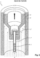
- Fig. 3 shows an NMR spectrometer 1 with a transport device according to the prior art, which instead could also be replaced by a transport device according to the invention.
- Fig. 5 Finally, the relationship between the distance traveled by the NMR measurement sample in a transport device according to the invention and the size of the gas flow with corresponding error bars for the axial position of the NMR test sample is shown.
- the total mass of the NMR measurement sample 2 to be transported is very small. Therefore, a large dynamics can be achieved with the lowest possible risk of damage to the NMR test sample.
- the possible complete omission of the transport carrier also allows the inner tube 6 and thus also the transport channel 3 to be dimensioned extremely small (typically 9 mm instead of 26 mm to date). This creates much additional space that can be used for example for a thermal insulation 8 against the NMR magnet and for an additional protective cover 9. As a result, unwanted temperature changes in the NMR test sample 2 during transport into the NMR spectrometer 1 can be further reduced.
Landscapes
- Physics & Mathematics (AREA)
- Condensed Matter Physics & Semiconductors (AREA)
- General Physics & Mathematics (AREA)
- Spectroscopy & Molecular Physics (AREA)
- High Energy & Nuclear Physics (AREA)
- Other Investigation Or Analysis Of Materials By Electrical Means (AREA)
- Sampling And Sample Adjustment (AREA)
Abstract
Eine Transporteinrichtung zur pneumatischen Beförderung von NMR-Messproben (2) von außerhalb eines NMR-Spektrometers (1) durch einen rohrförmigen Transportkanal (3) in das NMR-Spektrometer und von dort wieder nach außerhalb des NMR-Spektrometers, wobei die Transporteinrichtung eine Vorrichtung (4) zur Erzeugung von Überdruck in dem Spektrometer-abgewandten Ende des rohrförmigen Transportkanals umfasst, ist dadurch gekennzeichnet, dass der rohrförmige Transportkanal ein Rohrsystem aufweist, welches ein gasdichtes Außenrohr (5) mit Außendurchmesser Dund Innendurchmesser dsowie ein koaxial dazu angeordnetes Innenrohr (6) mit Außendurchmesser D< dund mit Innendurchmesser di umfasst, wobei der Innendurchmesser di des Innenrohrs größer oder gleich dem Außendurchmesser Dder NMR-Messproben gewählt ist, und dass das Innenrohr in axialer Richtung voneinander beabstandete, als Durchgangsbohrungen ausgeführte Querbohrungen (7) aufweist. Damit wird eine exakte und robuste Bestimmung der aktuellen Position der NMR-Messprobe im Transportkanal ermöglicht, wobei die Gefahr einer Beschädigung der NMR-Messprobe während ihres Transports deutlich verringert wird. Die Erfindung lässt sich ohne größere Umbauten optimal auch für vorhandene Systeme nach dem Stand der Technik einsetzen.A transport device for the pneumatic transport of NMR measurement samples (2) from outside an NMR spectrometer (1) through a tubular transport channel (3) into the NMR spectrometer and from there again outside the NMR spectrometer, the transport device being a device ( 4) for generating overpressure in the end of the tubular transport channel facing away from the spectrometer, characterized in that the tubular transport channel has a pipe system which has a gas-tight outer pipe (5) with an outer diameter D and an inner diameter d as well as an inner pipe (6) arranged coaxially therewith Outside diameter D <dand with inside diameter di, the inside diameter di of the inner tube being chosen to be greater than or equal to the outside diameter D of the NMR measurement samples, and that the inner tube has transverse bores (7) which are spaced apart from one another in the axial direction and are designed as through bores. This enables an exact and robust determination of the current position of the NMR measurement sample in the transport channel, whereby the risk of damage to the NMR measurement sample during transport is significantly reduced. The invention can also be used optimally for existing systems according to the prior art without major modifications.
Description
Die Erfindung betrifft eine Transporteinrichtung zur pneumatischen Beförderung von NMR-Messproben aus einem Bereich außerhalb eines NMR-Spektrometers durch einen rohrförmigen Transportkanal in das NMR-Spektrometer und von dort -gegebenenfalls nach Durchführung einer NMR-Messung an den NMR-Messproben- wieder nach außerhalb des NMR-Spektrometers, wobei die Transporteinrichtung eine Vorrichtung zur Erzeugung von Überdruck in dem NMR-Spektrometer-abgewandten Ende des rohrförmigen Transportkanals umfasst.The invention relates to a transport device for the pneumatic transport of NMR measurement samples from a region outside of an NMR spectrometer through a tubular transport channel in the NMR spectrometer and from there-optionally after performing an NMR measurement on the NMR Meßproben- again out of the NMR spectrometer, wherein the transport means comprises means for generating overpressure in the NMR spectrometer-remote end of the tubular transport channel.
NMR-Spektrometer mit derartigen Transporteinrichtungen werden bereits seit vielen Jahrzehnten von der Anmelderin hergestellt und vertrieben. Sie sind beispielsweise in der
Eine Transportvorrichtung zur pneumatischen Beförderung der NMR-Messproben ist bekannt aus der
Zur schnellen und exakten Analyse der chemischen Zusammensetzung von Messproben oder zur Strukturbestimmung von in den Proben enthaltenen Stoffen werden seit über einem halben Jahrhundert NMR-Verfahren eingesetzt. Diese können in NMR-Spektrometern durchgeführt werden. Für diese Zwecke geeignete NMR-Spektrometer sind beispielsweise in der
Die NMR-Spektroskopie ist ein leistungsfähiges Verfahren der instrumentellen Analytik. Bei diesen NMR-Verfahren ist die Probe einem starken statischen Magnetfeld B0 in einer z-Richtung ausgesetzt. Dabei kommt es zu einer Wechselwirkung mit den Kernspins des Probenmaterials, insbesondere zur Ausrichtung von Kernspins in der Messsubstanz. Sodann werden dazu orthogonale hochfrequente elektromagnetische Impulse in x- oder y-Richtung in die Probe eingestrahlt. Die zeitliche Entwicklung dieser Kernspins der Probe erzeugt wiederum hochfrequente elektromagnetische Felder, welche in der NMR-Apparatur detektiert werden. Aus den detektierten HF-Feldern können Informationen über die Eigenschaften der Probe integral über einen gewissen räumlichen Bereich erhalten werden. Insbesondere kann aus der Lage und Intensität von NMR-Linien auf die chemische Zusammensetzung sowie die chemischen Bindungsverhältnisse in der Probe geschlossen werden.NMR spectroscopy is a powerful method of instrumental analysis. In these NMR methods, the sample is exposed to a strong static magnetic field B 0 in a z-direction. This results in an interaction with the nuclear spins of the sample material, in particular for the orientation of nuclear spins in the measuring substance. Then orthogonal high-frequency electromagnetic pulses in the x or y direction are radiated into the sample. The temporal evolution of these nuclear spins of the sample in turn generates high-frequency electromagnetic fields, which are detected in the NMR apparatus. From the detected RF fields, information about the properties of the sample can be obtained integrally over a certain spatial range. In particular, it is possible to deduce the chemical composition and the chemical bonding conditions in the sample from the position and intensity of NMR lines.
Die Messprobe besteht in der Regel aus einem zylindrischen Probenröhrchen mit üblicherweise kreisrundem, ovalem oder rechteckigem Querschnitt, welches die feste oder flüssige Messsubstanz enthält. Das Probenröhrchen ist mindestens auf der Seite verschlossen, mit der es zuerst in den Probenkopf des NMR-Spektrometers eindringt, und befindet sich typischerweise in einem Transportbehälter, dem sogenannten Spinner. Probenröhrchen und Spinner werden mit Hilfe des Transportsystems von außerhalb des Magneten in den Probenkopf transportiert. Die eingangs zitierte Referenz [1] beschreibt eine Transportvorrichtung zum Befördern eines solchen Probenröhrchen zwischen einem Eingabepunkt, an dem es in die Transportvorrichtung eingesetzt und entnommen werden kann, und einem Zuführungspunkt, an dem das Probenröhrchen einem Raumtemperatur-Rohr eines Kryostaten zugeführt werden kann, wobei der Eingabepunkt zum Zuführungspunkt sowohl horizontal als auch vertikal beabstandet ist, und wobei ein rohrförmiger Transportkanal zum pneumatischen Befördern des Probenröhrchens von einem ersten Transferpunkt am unteren Ende des Transportrohrs zu einem zweiten Transferpunkt an dessen oberem Ende vorgesehen ist.The test sample usually consists of a cylindrical sample tube with a usually circular, oval or rectangular cross-section, which contains the solid or liquid measuring substance. The sample tube is closed at least on the side with which it first penetrates into the probe head of the NMR spectrometer, and is typically located in a transport container, the so-called spinner. Sample tubes and spinners are transported from outside the magnet into the sample head using the transport system. Reference cited at the beginning [1] describes a transport device for conveying such a sample tube between an input point where it can be inserted and removed in the transport device and a feed point at which the sample tube can be fed to a room temperature tube of a cryostat the feed point to the feed point is spaced both horizontally and vertically, and wherein a tubular transport channel is provided for pneumatically conveying the sample tube from a first transfer point at the lower end of the transfer tube to a second transfer point at the upper end thereof.
Im Folgenden wird davon ausgegangen, dass sich die Einführungsöffnung oben am Probenkopf des NMR-Spektrometers befindet und das Probenröhrchen also von oben in den Probenkopf eingeführt wird. Es ist jedoch auch denkbar, das Probenröhrchen von unten in eine dafür vorgesehene Öffnung in den Probenkopf einzuführen. Dieser Fall ist analog zum oben genannten und soll aus Gründen der Übersichtlichkeit hier nicht näher beschrieben werden. Wenn das Probenröhrchen in der Messposition angekommen ist, befindet sich der Spinner innerhalb einer Turbine. Diese Turbine ermöglicht eine Rotation des Probenröhrchens (siehe etwa
Einen Probenwechsler mit Transport von Temperatur-kontrollierten NMR-Messproben in ein NMR-Spektrometer beschreibt die
Die
Generell sollte die Tot-Zeit zwischen zwei aufeinanderfolgenden Messungen im NMR-System möglichst kurz sein. Die NMR-Messproben sollten daher möglichst schnell gewechselt werden können. Ein geeignetes automatisierbares, kompaktes Schnellwechselsystem mit einer Sensoreinrichtung zur Erkennung eines Transportbehälters sowie mit speziellen Parkaufnahmen zum zeitweiligen Zwischenspeichern eines im Spektrometer ankommenden Transportbehälters wird in der-am Anmeldetag der vorliegenden Patentanmeldung noch nicht veröffentlichten-
Wie auch schon oben angedeutet, wird üblicherweise die NMR-Messprobe in einen Transportträger (auch «Spinner» oder «Shuttle» genannt) gesteckt und dann mittels eines Gasstroms (meist Stickstoff oder Luft) in einem -theoretisch zylindrischen- Transportrohr transportiert. Die aktuelle Position des Transportträgers im Transportrohr ist jedoch nur schwer zu kontrollieren.As already indicated above, usually the NMR test sample is placed in a transport carrier (also called "spinner" or "shuttle") and then transported by means of a gas stream (usually nitrogen or air) in a -theoretically cylindrical transport tube. However, the current position of the transport carrier in the transport tube is difficult to control.
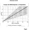
In der Regel existiert kein fester Zusammenhang zwischen der Stärke des Gaststroms und der Position des Transportträgers. Wie unten in
Der vorliegenden Erfindung liegt demgegenüber die Aufgabe zugrunde, eine Transporteinrichtung der eingangs definierten Art mit möglichst einfachen technischen Maßnahmen so zu modifizieren, dass die oben aufgezählten Nachteile vollständig oder zumindest weitestgehend vermieden werden, ohne damit eine Minderung der Qualität der NMR-Messungen hervorzurufen, wobei die NMR-Apparatur besonders kompakt bleiben soll und etwaige zusätzliche Materialkosten sowie weiterer Fertigungsaufwand unerheblich bleiben. Insbesondere soll die Erfindung eine möglichst exakte, aber auch technisch möglichst einfache und robuste Bestimmung der aktuellen Position der NMR-Messprobe im Transportkanal ermöglichen, wobei die Gefahr einer Beschädigung der NMR-Messprobe während ihres Transports durch den Transportkanal deutlich verringert werden soll. Die Erfindung soll außerdem problemlos eine wirksame Vortemperierung der Messproben möglich machen, so dass ein NMR-Experiment direkt nach dem Transport der jeweiligen Messprobe in das Magnetzentrum sofort und ohne weitere Vorbereitungszeit gestartet werden kann. Schließlich soll die erfindungsgemäße Änderung der bekannten Transporteinrichtung dahingehend konzipiert sein, dass sie ohne größere Umbauten optimal auch für vorhandene Systeme nach dem Stand der Technik einsetzbar ist, etwa für den SampleJet und den SampleCase der Anmelderin.The present invention is based on the object to modify a transport device of the type defined with the simplest possible technical measures so that the above enumerated disadvantages are completely or at least largely avoided, without causing a reduction in the quality of the NMR measurements, the NMR apparatus should remain particularly compact and any additional material costs and other manufacturing costs remain insignificant. In particular, the invention should allow the most accurate, but also technically simple and robust determination of the current position of the NMR sample in the transport channel, the risk of damage to the NMR sample is to be significantly reduced during their transport through the transport channel. The invention is also intended to make possible an effective pre-tempering of the test samples without problems, so that an NMR experiment directly after the transport of the respective Test sample can be started in the Magnetzentrum immediately and without further preparation time. Finally, the change of the known transport device according to the invention should be designed so that it can be optimally used without major modifications for existing systems according to the prior art, such as for the SampleJet and the SampleCase of the Applicant.
Diese relativ komplexe Aufgabe wird auf ebenso überraschend einfache wie wirkungsvolle Weise dadurch gelöst, dass bei einem gattungsgemäßen Transporteinrichtung zur pneumatischen Beförderung von NMR-Messproben mit den eingangs definierten Merkmalen der rohrförmige Transportkanal ein Rohrsystem umfasst, welches ein gasdichtes Außenrohr mit Außendurchmesser Da und Innendurchmesser da sowie ein koaxial dazu angeordnetes Innenrohr mit Außendurchmesser Di < da und mit Innendurchmesser di aufweist, wobei der Innendurchmesser di des Innenrohrs größer oder gleich dem Außendurchmesser DP der NMR-Messproben gewählt ist, und dass das Innenrohr in axialer Richtung voneinander beabstandete, als Durchgangsbohrungen ausgeführte Querbohrungen aufweist.This relatively complex task is solved in an astonishingly simple and effective manner by the fact that in a generic transport device for the pneumatic transport of NMR test specimens with the features defined above, the tubular transport channel comprises a pipe system comprising a gas-tight outer tube with outer diameter D a and inner diameter d a and a coaxially arranged inner tube with outer diameter D i <d a and with inner diameter d i , wherein the inner diameter d i of the inner tube is greater than or equal to the outer diameter D P of the NMR measurement samples selected, and that the inner tube in the axial direction from each other having spaced, designed as through holes transverse bores.
Die erfindungsgemäße Transporteinrichtung weist also im Gegensatz zur bisher üblichen Ausführung des einfachen Transportrohrs einen Transportkanal mit einem Doppelrohrsystem auf, das ein gasdichtes Außenrohr und ein mit radialem Abstand koaxial darin angeordnetes Innenrohr umfasst. Durch die erfindungsgemäß vorgeschriebenen Querbohrungen des Innenrohrs kann das aus der Überdruck-Vorrichtung eingepresste Transportgas jeweils zu einem gewissen Teil in den Hohlraum zwischen den beiden Rohren ausweichen. Durch den von der NMR-Messprobe im Innenrohr verursachten Gegendruck wird der Gasstrom jeweils unterhalb der NMR-Messprobe diese Ausweichmöglichkeit nutzen. Dies hat nun den großen Vorteil, dass je höher die NMR-Messprobe im inneren Transportrohr aufsteigt, umso mehr Gas durch diese kleinen Querlöcher verloren geht. Dadurch entsteht ein fester Zusammenhang zwischen der Größe des Gasstroms und der aktuellen Axialposition der NMR-Messprobe im inneren Transportrohr.The transport device according to the invention thus has, in contrast to the previously customary embodiment of the simple transport tube to a transport channel with a double tube system comprising a gas-tight outer tube and a radially spaced coaxially therein arranged inner tube. As a result of the transverse bores of the inner tube prescribed according to the invention, the transport gas injected from the overpressure device can in each case escape to some extent into the cavity between the two tubes. As a result of the back pressure caused by the NMR test sample in the inner tube, the gas flow below the NMR measurement sample becomes Use alternative way. This has the great advantage that the higher the NMR sample in the inner transport tube rises, the more gas is lost through these small transverse holes. This creates a fixed relationship between the size of the gas stream and the current axial position of the NMR sample in the inner transport tube.
In pneumatischer Hinsicht verhält sich also das erfindungsgemäße DoppelrohrSystem wie ein geometrisch konisch ausgestaltetes, in seinem Querschnitt von unten nach oben zum Spektrometer hin sich verjüngendes einfaches Transportrohr, welches aber natürlich deutlich schwieriger herzustellen ist als das erfindungsgemäße Doppelrohrsystem. Durch die Verwendung eines solchen «pneumatisch konischen» Transportrohrs ist die aktuelle Axialposition des Transportträgers direkt abhängig vom aktuellen Volumenstrom des Transportgases und somit zu jedem Zeitpunkt des Transportvorgangs -und zwar ohne Einsatz zusätzlicher aufwändiger Detektionseinrichtungen- im Prinzip bekannt. Außerdem entstehen durch die -zunächst frei positionierbaren sowie in ihrer Größe und Anzahl frei wählbaren- Querbohrungen in axialer Richtung des Doppelrohrsystems diverse Beschleunigungszonen, in welchen die NMR-Messprobe besonders flott transportiert werden kann.In pneumatic terms, therefore, the double tube system according to the invention behaves like a geometrically conically shaped, in its cross section from bottom to top towards the spectrometer towards tapered simple transport tube, but of course much more difficult to produce than the double tube system according to the invention. By using such a "pneumatically conical" transport tube, the current axial position of the transport carrier is known in principle directly depending on the current volume flow of the transport gas and thus at any time during the transport process - without the use of additional complex detection devices. In addition, arise through the first freely positionable and in their size and number freely selectable transverse holes in the axial direction of the double pipe system various acceleration zones in which the NMR test sample can be transported very fast.
Insgesamt kann damit ein sehr robuster, schonender und trotzdem besonders schneller Transport der NMR-Messprobe ohne die Notwendigkeit einer besonderen Kalibration für unterschiedliche Massen bewerkstelligt werden. Wird zudem die Masse des Transportträgers stark reduziert oder gar der Transportträger gänzlich weggelassen, können die Möglichkeiten für eine Beschädigung der NMR-Messprobe während ihres Transports massiv reduziert werden.Overall, this allows a very robust, gentle and nevertheless very fast transport of the NMR test sample without the need for a special calibration for different masses. If, in addition, the mass of the transport carrier is greatly reduced or even the transport carrier is omitted altogether, the possibilities for damaging the NMR test sample during its transport can be massively reduced.
Gerade aufgrund der durch die Erfindung eröffneten Möglichkeiten einer verbesserten automatisierten Schnellzuführung von -idealerweise sogar schon vortemperierten- NMR-Messproben wird es ermöglicht, den NMR-Messzyklus sehr kurz zu halten, da ein Vortemperieren der NMR-Messproben im Spektrometer problemlos auf die Zeitdauer des Transports der Proben durch den Transportkanal vorverlagert werden kann und somit nicht mehr den NMR-Messzyklus -unnötig- verlängert. Gerade durch diese zeitliche Verkürzung des Messzyklus ergeben sich hohe wirtschaftliche Vorteile, da mehr Messungen in der gleichen Zeit durchgeführt werden können.Precisely because of the possibilities opened by the invention of an improved automated rapid feed of-ideally even pre-tempered NMR test samples, it is possible to use the NMR measuring cycle To keep very short, since a pre-tempering of NMR spectroscopy samples in the spectrometer can be easily vorverlagert to the duration of transport of the samples through the transport channel and thus no longer extends the NMR measuring cycle -unless-. This shortening of the measuring cycle in particular results in high economic advantages since more measurements can be carried out in the same time.
An dieser Stelle sei ausdrücklich darauf hingewiesen, dass sich die Vorteile der Erfindung nicht nur bei vertikalen NMR-Spektrometern, sondern ebenso auch bei NMR-Systemen mit horizontaler oder schräg liegender z-Achse erzielen lassen. Die angegebenen axialen Positionen müssen dann nicht mehr notwendig "oberhalb" beziehungsweise "unterhalb" des NMR-Magnetspulensystems liegen, sondern gegebenenfalls auch "rechts" oder "links" neben demselben. Jedenfalls spielt die Schwerkraft bei der Wirkungsweise der vorliegenden Erfindung eine untergeordnete Rolle.It should be expressly pointed out that the advantages of the invention can be achieved not only in vertical NMR spectrometers, but also in NMR systems with a horizontal or oblique z-axis. The specified axial positions must then no longer necessarily be "above" or "below" the NMR magnet coil system, but optionally also "right" or "left" next to it. In any case, gravity plays a minor role in the operation of the present invention.
Je nach speziellem Einsatzzweck können Ausführungsformen der erfindungsgemäßen Transporteinrichtung von besonders hohem Nutzen sein, bei denen die Querbohrungen in axialer Richtung des Innenrohrs in unterschiedlichen Distanzen und/oder unterschiedlichen Querbohrungsdurchmessern angeordnet sind. Dies kann etwa von Vorteil sein, wenn ein nichtlineares Transportprofil (Gasfluss zur Transportdistanz) mit sanften Beschleunigungsphasen erforderlich ist, beispielsweise beim Transport von fragilen, dünnwandigen NMR-Probengläschen.Depending on the particular application, embodiments of the transport device according to the invention can be of particularly high utility, in which the transverse bores are arranged in the axial direction of the inner tube at different distances and / or different transverse bore diameters. This may be advantageous, for example, if a non-linear transport profile (gas flow for transport distance) with gentle acceleration phases is required, for example during the transport of fragile, thin-walled NMR sample vials.
Ganz besonders bevorzugt ist aber eine Klasse von Ausführungsformen der erfindungsgemäßen Transporteinrichtung, bei welchen die Querbohrungen in axialer Richtung des Innenrohrs äquidistant angeordnet sind. Dies kann besonders im mittleren Transportbereich zwischen Magnetzentrum und einer nach oben offenen Magnetbohrung vorteilhaft sein, wenn die NMR-Messprobe mit einer konstanten Geschwindigkeit befördert werden soll.But very particularly preferred is a class of embodiments of the transport device according to the invention, in which the transverse bores are arranged equidistantly in the axial direction of the inner tube. This can especially in the middle transport area between the magnet center and an upwardly open magnetic bore, if the NMR test sample is to be conveyed at a constant speed.
Weitere vorteilhafte Ausführungsformen der Erfindung sind dadurch gekennzeichnet, dass eine das Außenrohr umgebende thermische Isolationseinrichtung vorhanden ist. Durch ein temperiertes Transportrohr, vorzugsweise auf der für die NMR-Messprobe vorgesehenen Messtemperatur, kann erreicht werden, dass sich die Temperatur der NMR-Messprobe während des Transports nicht ändert. Dadurch kann die NMR-Messung sofort bei Ankunft im Probenkopf gestartet werden, ohne zusätzliche Wartezeit für die Temperaturstabilisierung.Further advantageous embodiments of the invention are characterized in that a surrounding the outer tube thermal insulation device is present. By means of a temperature-controlled transport tube, preferably at the measurement temperature provided for the NMR test sample, it is possible to ensure that the temperature of the NMR test sample does not change during transport. As a result, the NMR measurement can be started immediately upon arrival in the probe head, without additional waiting time for the temperature stabilization.
Bevorzugt ist auch eine Ausführungsform der erfindungsgemäßen Transporteinrichtung, bei der eine Schutzhülle das Rohrsystem umgibt. Dadurch wird die oftmals sehr empfindliche thermische Isolation soweit geschützt, dass sie beim Ein- und -Ausbau des Systems nicht beschädigt oder verletzt werden kann.Also preferred is an embodiment of the transport device according to the invention, in which a protective casing surrounds the pipe system. As a result, the often very sensitive thermal insulation is protected to such an extent that it can not be damaged or injured during installation and removal of the system.
Des Weiteren ist auch eine Klasse von Ausführungsformen der Erfindung von Vorteil, bei welchen die Transporteinrichtung eine Vorrichtung zur Erzeugung von Unterdruck in dem NMR-Spektrometer-zugewandten Ende des rohrförmigen Transportkanals umfasst. Ein Ansaugen der NMR-Probe ist vorteilhaft für das Gasflusssystem im NMR-Probenkopf, indem das aus dem NMR-Probenkopf austretende Temperier-Gas ungehindert abfließen kann und zudem ein Ansaugen der NMR-Probe aus einem Speicher (z.B. Rack) und auch der NMR-Messzelle in einfacher Weise umsetzbar ist.Furthermore, a class of embodiments of the invention is also advantageous in which the transport device comprises a device for generating negative pressure in the NMR spectrometer-facing end of the tubular transport channel. An aspiration of the NMR sample is advantageous for the gas flow system in the NMR probe head, in that the tempering gas emerging from the NMR probe head can flow away unhindered and, moreover, a suction of the NMR sample from a memory (eg rack) and also the NMR Measuring cell can be implemented in a simple manner.
Bei weiteren bevorzugten Ausführungsformen ist das erfindungsgemäße Doppelrohrsystem so gestaltet, dass es radial innerhalb eines Standard-Transportrohrs nach dem Stand der Technik angeordnet werden kann.In other preferred embodiments, the dual tube system of the present invention is configured to be radially disposed within a standard prior art transport tube.
Dies hat den Vorteil, dass auch bestehende NMR-Magnetsysteme mit dem neuen Transportsystem nachgerüstet werden können, was dem Umstand Rechnung trägt, dass die NMR-Magneten typischerweise eine sehr hohe Lebens- und Verwendungsdauer von 20-30 Jahre besitzen.This has the advantage that even existing NMR magnetic systems can be retrofitted with the new transport system, which takes into account the fact that the NMR magnets typically have a very long life and use of 20-30 years.
In der Praxis bewähren sich auch Ausführungsformen, bei welchen das Rohrsystem folgende Dimensionierungen aufweist:
- Außendurchmesser Da des Außenrohrs: 15mm ≤ Da ≤ 30mm, vorzugsweise 18mm ≤ Da ≤ 26mm;
- Innendurchmesser da des Außenrohrs: 10mm ≤ da ≤ 25mm, vorzugsweise 15mm ≤ da ≤ 20mm;
- Außendurchmesser Di des Innenrohrs: 7,5mm ≤ Di ≤ 15mm, vorzugsweise 10mm ≤ Di ≤ 12mm;
- Innendurchmesser di des Innenrohrs: 5mm ≤ di ≤ 10mm, vorzugsweise 8,5mm ≤ di ≤ 9,5mm;
- axialer Abstand AQ der Querbohrungen: 50mm ≤ AQ ≤ 300mm.
- Outer diameter D a of the outer tube: 15mm ≤ D a ≤ 30mm, preferably 18mm ≤ D a ≤ 26mm;
- Inner diameter da of the outer tube: 10mm ≤ d a ≤ 25mm, preferably 15mm ≤ d a ≤ 20mm;
- Outer diameter D i of the inner tube: 7.5 mm ≦ D i ≦ 15 mm, preferably 10 mm ≦ D i ≦ 12 mm;
- Inner diameter d i of the inner tube: 5mm ≦ d i ≦ 10mm, preferably 8.5mm ≦ d i ≦ 9.5mm;
- axial distance A Q of the transverse holes: 50mm ≤ A Q ≤ 300mm.
Vorteilhaft sind Ausführungsformen der erfindungsgemäßen Transporteinrichtung, bei denen die NMR-Messproben im Betrieb von einem Transportbehälter umgeben sind, dessen Masse MT << 50g, insbesondere MT < 40g, vorzugsweise MT ≤ 25g. Dies ist vorteilhaft, da die aktuellen Standard-Transportbehälter auch beim neuen Transportverfahren verwendet werden können, was sich auch auf die Akzeptanz beim Kunden positiv auswirken kann, da er seine vielen Transportbehälter weiterverwenden kann.Embodiments of the transport device according to the invention in which the NMR measurement samples are surrounded during operation by a transport container whose mass M T << 50 g, in particular M T <40 g, preferably M T ≦ 25 g, are advantageous. This is advantageous because the current standard transport containers can also be used in the new transport method, which can also have a positive effect on the acceptance by the customer, since he can continue to use his many transport containers.
Besonders bevorzugt schließlich ist eine Klasse von Ausführungsformen der erfindungsgemäßen Transporteinrichtung, die sich dadurch auszeichnen, dass sich die NMR-Messproben im Betrieb jeweils in einem, vorzugsweise zylindrischen, Probenröhrchen mit Außendurchmesser DPR befinden, und dass die Probenröhrchen im Betrieb jeweils durch eine einseitig aufgebrachte Verschlusskappe mit maximalem Außendurchmesser DVK fluiddicht verschlossen sind. Durch den Verzicht auf den, im Vergleich zum Gewicht der NMR-Messprobe schweren Transportbehälter, können viel schnellere Transportzyklen mit entsprechend höheren Beschleunigungen verwendet werden, ohne Gefahr zu laufen, dass die empfindliche NMR-Messprobe beschädigt wird, z.B. das Glas bricht etc. Des Weiteren wird durch das reduzierte Gewicht auch eine erhebliche Reduktion des Verbrauchs an Transportgasen erreicht.Particularly preferred finally is a class of embodiments of the transport device according to the invention, which are characterized in that the NMR measurement samples are in operation in each case in a, preferably cylindrical, sample tube with outer diameter D PR , and that the sample tubes in each case by a one-sided applied Closure cap with maximum outside diameter D VK are sealed fluid-tight. By dispensing with the transport container, which is heavy in comparison to the weight of the NMR test sample, much faster transport cycles with correspondingly higher accelerations can be used without running the risk of damaging the sensitive NMR sample, eg breaking the glass, etc. Furthermore The reduced weight also achieves a significant reduction in the consumption of transport gases.
Bei vorteilhaften Weiterbildungen dieser Klasse von Ausführungsformen sind die Probenröhrchen und die Verschlusskappen so dimensioniert sind, dass gilt: di ≥ DVK > DPR. Die Verschlusskappe übernimmt zugleich die Funktion der Dichtlippe um den Auftrieb im Transportrohr zu generieren. Die bestehenden Verschlusskappen der Standard-4Zoll NMR-Messproben können diese Funktion bereits heute erfüllen.In advantageous developments of this class of embodiments, the sample tubes and the closure caps are dimensioned such that: d i ≥ D VK > D PR . The cap also takes over the function of the sealing lip to generate the buoyancy in the transport tube. The existing caps of standard 4-inch NMR probes can already fulfill this function today.
In den Rahmen der vorliegenden Erfindung fällt auch ein Verfahren zum Betrieb einer erfindungsgemäßen Transporteinrichtung der oben beschriebenen Art, mit folgenden Schritten:
- (a) Zuführung einer von einer Aufgabestelle, insbesondere einem Präparationsroboter, außerhalb des NMR-Spektrometers übernommenen NMR-Messprobe durch den externen Teil des Transportkanals zum Eintrittspunkt in das NMR-Spektrometer;
- (b) Umsetzen der NMR-Messprobe in eine für den Weitertransport in den NMR-Magneten günstige räumliche Lage, vorzugsweise parallel zur Magnet-Achse;
- (c) pneumatisch kontrolliertes Einführen der NMR-Messprobe durch den internen Teil des Transportkanals in das Magnetzentrum des NMR-Magnetsystems;
- (d) Durchführen einer NMR-Messung an der NMR-Messprobe im Magnetzentrum des NMR-Systems;
- (e) pneumatischer Rücktransport der NMR-Messprobe aus dem Magnetzentrum nach außerhalb des NMR-Spektrometers;
- (f) gegebenenfalls Weitertransport der vermessenen NMR-Messprobe durch den externen Teile des Transportkanal zurück zur Aufgabestelle, z.B. einem Präparationsroboter.
- (A) feeding an NMR measurement sample taken from a feed point, in particular a preparation robot, outside the NMR spectrometer through the external part of the transport channel to the entry point into the NMR spectrometer;
- (b) converting the NMR test sample into a favorable spatial position for further transport into the NMR magnet, preferably parallel to the magnet axis;
- (c) pneumatically controlled introduction of the NMR measurement sample through the internal part of the transport channel into the magnetic center of the NMR magnet system;
- (d) performing an NMR measurement on the NMR measurement sample in the magnetic center of the NMR system;
- (e) pneumatic return transport of the NMR test sample from the magnetic center to the outside of the NMR spectrometer;
- (f) optionally further transport of the measured NMR measurement sample through the external parts of the transport channel back to the point of application, eg a preparation robot.
Bei einem NMR-Spektrometer mit vertikal angeordneter Raumtemperatur-Bohrung befindet sich der Eintrittspunkt in der Regel oben auf dem NMR-System. Die bevorzugte Positionierung des Probenröhrchens mit der NMR-Messprobe in Schritt (b) wird dann so erfolgen, dass die Längsachse des Röhrchens in der Senkrechten steht. Möglicherweise sind auf dem NMR-System auch bereits mehrere andere NMR-Messproben gelagert, die alle auf die bevorzugte NMR-Messtemperatur gebracht, zumeist erhitzt, und/oder auf der gewünschten Temperatur gehalten werden. Ein erheblicher Vorteil dieses Verfahrens ist unter anderem ein schneller Wechsel der jeweils zu vermessenden Probe sowie ein zuverlässigerer Transport bei unterschiedlich schweren NMR-Messproben als dies heute möglich ist.In an NMR spectrometer with a vertically arranged room temperature bore, the entry point is usually at the top of the NMR system. The preferred positioning of the sample tube with the NMR measurement sample in step (b) is then carried out so that the longitudinal axis of the tube is in the vertical. It is also possible that several other NMR test samples are already stored on the NMR system, all of which have been brought to the preferred NMR measurement temperature, mostly heated, and / or maintained at the desired temperature. A significant advantage of this method is inter alia a rapid change of the sample to be measured in each case as well as a more reliable transport with different NMR measurement samples than is possible today.
Vorteilhafte Weiterbildungen dieses Verfahrens sind dadurch gekennzeichnet, dass aus dem Verhältnis der aus den Querbohrungen austretenden Luft zum Gesamtvolumenstrom und dem dadurch vorliegenden direkten Zusammenhang zwischen Gesamtvolumenstrom und der axialen Position einer NMR-Messprobe im Transportkanal die aktuelle axiale Position der NMR-Messprobe bekannt ist. Dies erlaubt einen zuverlässigeren Betrieb mit kürzeren Wechselzeiten auch bei herstellungsbedingten Variationen in der Geometrie wie auch dem Gewicht der NMR-Messprobe.Advantageous developments of this method are characterized in that the current axial position of the NMR measurement sample is known from the ratio of the air emerging from the transverse bores to the total volume flow and the direct relationship between the total volume flow and the axial position of an NMR test sample in the transport channel. This allows a more reliable operation with shorter changeover times even with production-related variations in the geometry as well as the weight of the NMR test sample.
Alternativ oder ergänzend können auch Weiterbildungen des erfindungsgemäßen Verfahrens zum Einsatz gelangen, bei welchen das Innenrohr unter Ausnutzung der das Außenrohr umgebenden thermischen Isolationseinrichtung auf einer konstanten Temperatur, vorzugsweise auf der Temperatur der NMR-Probe während der NMR-Messung gehalten wird, wobei diese Temperatur von der ungeregelten Temperatur des Transportkanals thermisch isoliert ist.Alternatively or additionally, developments of the method according to the invention can also be used, in which the inner tube is kept at a constant temperature, preferably at the temperature of the NMR sample during the NMR measurement, utilizing the thermal insulation device surrounding the outer tube, this temperature being the unregulated temperature of the transport channel is thermally insulated.
Durch ein temperiertes Transportrohr, vorzugsweise auf der für die NMR-Messprobe vorgesehenen Messtemperatur, kann erreicht werden, dass sich die Temperatur der NMR-Messprobe während des Transports nicht ändert. Dadurch kann die NMR-Messung sofort bei Ankunft im Probenkopf gestartet werden, ohne zusätzliche Wartezeit für die Temperaturstabilisierung.By means of a temperature-controlled transport tube, preferably at the measurement temperature provided for the NMR test sample, it is possible to ensure that the temperature of the NMR test sample does not change during transport. As a result, the NMR measurement can be started immediately upon arrival in the probe head, without additional waiting time for the temperature stabilization.
Besonders bevorzugt sind auch Varianten des erfindungsgemäßen Verfahrens, welche sich dadurch auszeichnen, dass die NMR-Messprobe zur Durchführung einer NMR-Messung zusätzlich zu einem Anblasen durch die Vorrichtung zur Erzeugung von Überdruck auch mittels der Vorrichtung zur Erzeugung von Unterdruck in das NMR-Spektrometer gesaugt wird. Ein Ansaugen der NMR-Messprobe ist vorteilhaft für das Gasflusssystem im NMR-Probenkopf, weil dadurch das aus dem NMR-Probenkopf austretende Temperiergas ungehindert abfließen kann und zudem ein Ansaugen der NMR-Messprobe aus einem Speicher (z.B. einem Rack) und auch einer NMR-Messzelle technisch einfach umsetzbar ist.Variants of the method according to the invention are also particularly preferred, which are distinguished by the fact that the NMR measurement sample is also sucked into the NMR spectrometer by means of the device for generating negative pressure for carrying out an NMR measurement in addition to blowing through the device for generating overpressure becomes. Suction of the NMR test sample is advantageous for the gas flow system in the NMR probe head, because it allows the tempering gas leaving the NMR probe head to flow away unhindered and additionally aspirates the NMR test sample from a memory (eg a rack) and also an NMR probe. Measuring cell is technically easy to implement.
In den Rahmen der vorliegenden Erfindung schließlich fällt auch ein NMR-Spektrometer mit einer erfindungsgemäß modifizierten Transporteinrichtung der oben beschriebenen Art.Finally, the scope of the present invention also includes an NMR spectrometer with a transport device according to the invention of the type described above.
Weitere Vorteile der Erfindung ergeben sich aus der Beschreibung und der Zeichnung. Ebenso können die vorstehend genannten und die noch weiterausgeführten Merkmale erfindungsgemäß jeweils einzeln für sich oder zu mehreren in beliebigen Kombinationen Verwendung finden. Die gezeigten und beschriebenen Ausführungsformen sind nicht als abschließende Aufzählung zu verstehen, sondern haben vielmehr beispielhaften Charakter für die Schilderung der Erfindung.Further advantages of the invention will become apparent from the description and the drawings. Likewise, the features mentioned above and further developed according to the invention can each individually for themselves or to several in any combination use find. The embodiments shown and described are not to be understood as exhaustive enumeration, but rather have exemplary character for the description of the invention.
Die Erfindung ist in der Zeichnung dargestellt und wird anhand von Ausführungsbeispielen näher erläutert.The invention is illustrated in the drawing and will be explained in more detail with reference to embodiments.
Es zeigen:
- Fig. 1
- eine schematisierte, teilweise Vertikalschnitt-Ansicht auf eine Ausführungsform der erfindungsgemäßen Transporteinrichtung mit einer NMR-Messprobe ohne Transportbehälter, aber mit Verschlusskappe;
- Fig. 2
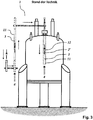
- eine schematische vertikale Schnittansicht einer Transporteinrichtung nach dem Stand der Technik;
- Fig. 3
- eine teil-transparente vertikale Schnittansicht eines NMR-Spektrometers mit einer Transporteinrichtung nach dem Stand der Technik;
- Fig. 4
- Zusammenhang zwischen der von der NMR-Messprobe in einer Transporteinrichtung nach dem Stand der Technik zurückgelegten Distanz und der Größe des Gasstroms mit entsprechenden Fehlerbalken für die axiale Position der NMR-Messprobe; und
- Fig. 5
- der Zusammenhang aus
Fig. 4 bei einer erfindungsgemäßen Transporteinrichtung.
- Fig. 1
- a schematic, partial vertical sectional view of an embodiment of the transport device according to the invention with an NMR test sample without transport container, but with cap;
- Fig. 2
- a schematic vertical sectional view of a transport device according to the prior art;
- Fig. 3
- a partially transparent vertical sectional view of an NMR spectrometer with a transport device according to the prior art;
- Fig. 4
- Relationship between the distance traveled by the NMR sample in a prior art conveyor and the magnitude of the gas flow with corresponding error bars for the axial position of the NMR sample; and
- Fig. 5
- the connection
Fig. 4 in a transport device according to the invention.
Generell befasst sich die vorliegende Erfindung mit einer modifizierten Transporteinrichtung von Messproben zu und von einem NMR-Spektrometer 1. Die Vorteile der Erfindung können aber auch bei einem Spektrometer mit anderer physikalischer Messtechnik genutzt werden, wobei dann womöglich entsprechende geeignete Modifikationen vorgenommen werden müssen.In general, the present invention is concerned with a modified transport device of measurement samples to and from an
Bereits im Stand der Technik weist eine solche Transporteinrichtung zur pneumatischen Beförderung von NMR-Messproben 2 aus einem Bereich außerhalb eines NMR-Spektrometers 1 durch einen rohrförmigen Transportkanal 3 in das NMR-Spektrometer 1 und von dort -gegebenenfalls nach Durchführung einer NMR-Messung an den NMR-Messproben 2- wieder nach außerhalb des NMR-Spektrometers 1 eine Vorrichtung 4 zur Erzeugung von Überdruck in dem NMR-Spektrometer-abgewandten Ende des rohrförmigen Transportkanals 3 auf.Already in the prior art has such a transport device for the pneumatic transport of
Die erfindungsgemäße Transporteinrichtung zeichnet sich demgegenüber dadurch aus, dass der rohrförmige Transportkanal 3 ein Rohrsystem umfasst, welches ein gasdichtes Außenrohr 5 mit Außendurchmesser Da und Innendurchmesser da sowie ein koaxial dazu angeordnetes Innenrohr 6 mit Außendurchmesser Di < da und mit Innendurchmesser di aufweist, wobei der Innendurchmesser di des Innenrohrs 6 größer oder gleich dem Außendurchmesser DP der NMR-Messproben 2 gewählt ist, und dass das Innenrohr 6 in axialer Richtung voneinander beabstandete, als Durchgangsbohrungen ausgeführte Querbohrungen 7 aufweist.The transport device according to the invention is characterized by the fact that the
Die Querbohrungen 7 können prinzipiell an beliebigen axialen Positionen des Innenrohrs 6 vorgesehen werden. Bei dem in
Bei dieser Ausführungsform ist außerdem eine das Außenrohr 5 umgebende thermische Isolationseinrichtung 8 vorhanden. Außerdem umgibt hier eine Schutzhülle 9 das Rohrsystem 5, 6. Schließlich umfasst bei diesem Ausführungsbeispiel der Erfindung die Transporteinrichtung eine Vorrichtung 10 zur Erzeugung von Unterdruck in dem NMR-Spektrometer-zugewandten Ende des rohrförmigen Transportkanals 3. Das "pseudo-konische" DoppelrohrSystem 5, 6 kann also sowohl mittels der Vorrichtung 4 angeblasen als auch durch die Vorrichtung 10 abgesaugt werden.In this embodiment, a surrounding the
Üblicherweise befinden sich die NMR-Messproben 2 im Betrieb jeweils in einem, vorzugsweise zylindrischen, Probenröhrchen 2' mit Außendurchmesser DPR. Im Betrieb sind diese Probenröhrchen 2' jeweils durch eine einseitig aufgebrachte Verschlusskappe 2" mit maximalem Außendurchmesser DVK fluiddicht verschlossen. Die Probenröhrchen 2' und die Verschlusskappen 2" sind dabei so dimensioniert, dass gilt: di ≥ DVK > DPR.Usually, the
Bei -in der vorliegenden Zeichnung nicht eigens dargestellten- weiteren Ausführungsformen der Erfindung kann aber auch das Doppelrohrsystem 5, 6 der erfindungsgemäßen Transporteinrichtung radial innerhalb eines vorhandenen herkömmlichen Standard-Transportrohrs 11 nach dem Stand der Technik angeordnet werden, wodurch eine Ab-Kompatibilität zu vorhandenen Einrichtungen hergestellt wird. Außerdem können bei Ausführungsformen der Erfindung die NMR-Messproben 2 im Betrieb ebenfalls von einem Transportbehälter 12 umgeben sein. Dieser wird jedoch in der Regel eine erheblich geringere Masse MT als der beim Stand der Technik übliche Transportbehälter aufweisen, nämlich MT << 50g, insbesondere MT < 40g, vorzugsweise MT ≤ 25g.In addition to the present drawing not specifically illustrated further embodiments of the invention but also the
In
Durch die oben beschriebene erfindungsgemäße Modifikation der Transporteinrichtung entsteht ein fester Zusammenhang zwischen Gasstrom und Position der NMR-Messprobe 2 im Transportkanal 3, welcher in
Durch das völlige Fehlen oder zumindest das erhebliche Verkleinern des Transportträgers 12 ist die Gesamtmasse der zu transportierenden NMR-Messprobe 2 sehr klein. Daher ist eine große Dynamik erreichbar bei gleichzeitig kleinstem Risiko einer Beschädigung der NMR-Messprobe. Der mögliche vollständige Wegfall des Transportträgers erlaubt zudem, das Innenrohr 6 und damit auch den Transportkanal 3 äußerst klein zu dimensionieren (typischerweise 9mm anstelle von bisher 26mm). Dadurch entsteht viel zusätzlicher Bauraum, der beispielsweise für eine thermische Isolierung 8 gegenüber dem NMR-Magneten sowie für eine zusätzliche Schutzhülle 9 genutzt werden kann. Hierdurch lassen sich unerwünschte Temperaturänderungen in der NMR-Messprobe 2 während des Transports ins NMR-Spektrometer 1 noch weiter reduzieren.Due to the complete absence or at least the considerable reduction of the
- 11
- NMR- SpektrometerNMR spectrometer
- 22
- NMR-MessprobeNMR measurement sample
- 2'2 '
- Probenröhrchensample tubes
- 2"2 '
- Verschlusskappecap
- 33
- Transportkanaltransport channel
- 44
- Vorrichtung zur Erzeugung von ÜberdruckDevice for generating overpressure
- 55
- Außenrohrouter tube
- 66
- Innenrohrinner tube
- 77
- Querbohrungencross holes
- 88th
- Thermische IsolationseinrichtungThermal insulation device
- 99
- Schutzhüllecover
- 1010
- Vorrichtung zur Erzeugung von UnterdruckDevice for generating negative pressure
- 1111
- Standard-TransportrohrStandard transport pipe
- 1212
- Transportbehältertransport container
Für die Beurteilung der Patentfähigkeit in Betracht gezogene Publikationen:
- [1]
DE 37 29 819 C2 - [2]
Firmenbroschüre Z31123 "Bruker Sample Transport. BST Installation and Technical Manual Version 002" der Bruker BioSpin AG vom 21. November 2008 - [3]
EP 2 199 816 B1US 8,217,655 B2 - [4]
DE 10 2013 212 312 B4 - [5]
US 6,768,305 B1 - [6]
DE 10 2014 201 076 B3 - [7]
DE 10 2018 201 226.1
- [1]
DE 37 29 819 C2 - [2]
Company Brochure Z31123 "Bruker Sample Transport BST Installation and Technical Manual Version 002" of Bruker BioSpin AG, November 21, 2008 - [3]
EP 2 199 816 B1US 8,217,655 B2 - [4]
DE 10 2013 212 312 B4 - [5]
US 6,768,305 B1 - [6]
DE 10 2014 201 076 B3 - [7]
DE 10 2018 201 226.1
Claims (15)
dadurch gekennzeichnet,
dass der rohrförmige Transportkanal (3) ein Rohrsystem (5, 6) umfasst, welches ein gasdichtes Außenrohr (5) mit Außendurchmesser Da und Innendurchmesser da sowie ein koaxial dazu angeordnetes Innenrohr (6) mit Außendurchmesser Di < da und mit Innendurchmesser di aufweist, wobei der Innendurchmesser di des Innenrohrs (6) größer oder gleich dem Außendurchmesser DP der NMR-Messproben (2) gewählt ist,
und dass das Innenrohr (6) in axialer Richtung voneinander beabstandete, als Durchgangsbohrungen ausgeführte Querbohrungen (7) aufweist.Transport device for the pneumatic transport of NMR test samples (2) from a region outside an NMR spectrometer (1) through a tubular transport channel (3) into the NMR spectrometer (1) and from there back to the outside of the NMR spectrometer (1) wherein the transport device comprises a device (4) for generating overpressure in the NMR spectrometer-remote end of the tubular transport channel (3),
characterized,
that the tubular transport channel (3) comprises a pipe system (5, 6) comprising a gas-tight outer tube (5) with an outer diameter D A and inner diameter d a and a coaxially arranged inner tube (6) with an outer diameter D i <d a and with an inner diameter d i , wherein the inner diameter d i of the inner tube (6) is greater than or equal to the outer diameter D P of the NMR test samples (2),
and that the inner tube (6) in the axial direction spaced apart, designed as through holes transverse bores (7).
Applications Claiming Priority (1)
| Application Number | Priority Date | Filing Date | Title |
|---|---|---|---|
| DE102018205535.1A DE102018205535B3 (en) | 2018-04-12 | 2018-04-12 | Transport device for tempered NMR test samples with double tube system |
Publications (2)
| Publication Number | Publication Date |
|---|---|
| EP3553545A1 true EP3553545A1 (en) | 2019-10-16 |
| EP3553545B1 EP3553545B1 (en) | 2020-12-09 |
Family
ID=66092190
Family Applications (1)
| Application Number | Title | Priority Date | Filing Date |
|---|---|---|---|
| EP19167319.3A Active EP3553545B1 (en) | 2018-04-12 | 2019-04-04 | Transport device for temperature-controlled nmr measuring samples with double-tube system |
Country Status (3)
| Country | Link |
|---|---|
| US (1) | US10782369B2 (en) |
| EP (1) | EP3553545B1 (en) |
| DE (1) | DE102018205535B3 (en) |
Families Citing this family (4)
| Publication number | Priority date | Publication date | Assignee | Title |
|---|---|---|---|---|
| CN115078436B (en) * | 2022-06-14 | 2025-05-06 | 上海科技大学 | A biological sample encapsulation and transfer method suitable for solid nuclear magnetic resonance research and a matching centrifugal device |
| DE102022210010A1 (en) | 2022-09-22 | 2024-03-28 | Bruker Switzerland Ag | Holding NMR measurement samples in a space-limited NMR spectrometer |
| DE102024206558B3 (en) | 2024-07-11 | 2025-09-25 | Bruker Switzerland Ag | NMR apparatus with flexible tube for sample transport |
| US12467992B1 (en) | 2025-07-03 | 2025-11-11 | Bruker Switzerland Ag | NMR apparatus with flexible sample transport tube |
Citations (1)
| Publication number | Priority date | Publication date | Assignee | Title |
|---|---|---|---|---|
| US20150198681A1 (en) * | 2014-01-15 | 2015-07-16 | Prudhvi Raju Chintalapati | Method for transporting an NMR sample spaced horizontally and vertically from a cryo-magnetic system using a vibration isolated motorized curvilinear Transport Carrier with dual end-effector and method for telescoping the Carrier to different cryo-magnetic systems at different heights |
Family Cites Families (9)
| Publication number | Priority date | Publication date | Assignee | Title |
|---|---|---|---|---|
| DE3729819A1 (en) | 1987-09-05 | 1989-03-16 | Spectrospin Ag | MAGNETIC ARRANGEMENT FOR NMR SPECTROMETERS |
| DE10111674C2 (en) * | 2001-03-09 | 2003-02-06 | Bruker Biospin Ag Faellanden | Device for transporting and accurately positioning a sample tube in a high-resolution NRM spectrometer |
| US6768305B1 (en) | 2003-09-26 | 2004-07-27 | Varian, Inc. | Temperature controlled sample changer for NMR analysis |
| JP4291304B2 (en) * | 2005-07-11 | 2009-07-08 | 株式会社日立製作所 | NMR probe |
| DE102008063703B3 (en) | 2008-12-19 | 2010-06-17 | Bruker Biospin Ag | Automatic transport device for NMR test specimens, automatic transport device cryomagnet system, automatic transport device transport container and method for carrying an NMR measurement sample |
| DE102013212312B4 (en) * | 2013-06-26 | 2017-02-02 | Bruker Biospin Ag | NMR probe head with improved centering of the sample tube |
| DE102014201076B3 (en) | 2014-01-22 | 2015-03-05 | Bruker Biospin Ag | Transport container for an NMR MAS rotor |
| US10281416B2 (en) * | 2014-08-04 | 2019-05-07 | Waters Technologies Corporation | Devices for use in solid-state NMR analysis |
| JP6528041B2 (en) * | 2015-02-06 | 2019-06-12 | 日本電子株式会社 | NMR probe |
-
2018
- 2018-04-12 DE DE102018205535.1A patent/DE102018205535B3/en not_active Expired - Fee Related
-
2019
- 2019-04-04 EP EP19167319.3A patent/EP3553545B1/en active Active
- 2019-04-11 US US16/381,054 patent/US10782369B2/en active Active
Patent Citations (1)
| Publication number | Priority date | Publication date | Assignee | Title |
|---|---|---|---|---|
| US20150198681A1 (en) * | 2014-01-15 | 2015-07-16 | Prudhvi Raju Chintalapati | Method for transporting an NMR sample spaced horizontally and vertically from a cryo-magnetic system using a vibration isolated motorized curvilinear Transport Carrier with dual end-effector and method for telescoping the Carrier to different cryo-magnetic systems at different heights |
Also Published As
| Publication number | Publication date |
|---|---|
| DE102018205535B3 (en) | 2019-07-04 |
| EP3553545B1 (en) | 2020-12-09 |
| US10782369B2 (en) | 2020-09-22 |
| US20190317162A1 (en) | 2019-10-17 |
Similar Documents
| Publication | Publication Date | Title |
|---|---|---|
| DE102018205535B3 (en) | Transport device for tempered NMR test samples with double tube system | |
| DE10111674C2 (en) | Device for transporting and accurately positioning a sample tube in a high-resolution NRM spectrometer | |
| DE102014201076B3 (en) | Transport container for an NMR MAS rotor | |
| DE102013212312B4 (en) | NMR probe head with improved centering of the sample tube | |
| EP3162443B1 (en) | Needle guide for centering of septum piercing | |
| EP3715893B1 (en) | Nmr spectrometer with quick swap system for samples | |
| EP2577285B1 (en) | Method for preparing sample for chromatographic separation and device for conducting sample preparation | |
| EP3175279B1 (en) | Light microscope having a sample stage for cryomicroscopy | |
| EP0592816A1 (en) | Directly coupled system for sample change for us in liquid NMR spectroscopy | |
| DE19509062A1 (en) | NMR spectrometer microlitre sample holder | |
| DE102015103657A1 (en) | thermal analyzer | |
| DE102009030471A1 (en) | Chuck for receiving and holding a test substrate and a calibration substrate | |
| DE10130283C1 (en) | NMR sample holder and associated operating procedures | |
| DE102007044016A1 (en) | Sample exchange device with guided on meandering path samples, especially for an NMR spectrometer | |
| EP1926971A1 (en) | Method and arrangement for the contactless inspection of moving electrically conductive substances | |
| EP3279618B1 (en) | Calibration device and method for dosing of delivery units | |
| DE102013219453B3 (en) | Dynamic nuclear polarization-device for producing hyperpolarized liquid for nuclear magnetic resonance- and magnetic resonance imaging-measurements, has cryostat which has opening and load path for loading cryostat with measuring sample | |
| DE10343405B4 (en) | NMR spectrometer with gripping device for handling a sample tube with outer groove | |
| EP3171191A1 (en) | Variable angle measuring head of an nmr mas apparatus | |
| EP1918731B1 (en) | Sample container for NMR measurements with homogenisation of sample volume by sample container boundaries | |
| DE102012008249B4 (en) | Improved resolution for ion mobility spectrometer | |
| EP2088419A2 (en) | Device and method for detecting defects of mono or polycrystalline silicon discs | |
| EP3458868A1 (en) | Transport device for an nmr mas rotor in a probe head ("mas shuttle") | |
| EP2843436B1 (en) | NMR spectrometer with ergonomically favourable sample exchanger | |
| EP3889630B1 (en) | Magnetic-compensated nmr rotor and method of design and manufacture |
Legal Events
| Date | Code | Title | Description |
|---|---|---|---|
| PUAI | Public reference made under article 153(3) epc to a published international application that has entered the european phase |
Free format text: ORIGINAL CODE: 0009012 |
|
| STAA | Information on the status of an ep patent application or granted ep patent |
Free format text: STATUS: THE APPLICATION HAS BEEN PUBLISHED |
|
| AK | Designated contracting states |
Kind code of ref document: A1 Designated state(s): AL AT BE BG CH CY CZ DE DK EE ES FI FR GB GR HR HU IE IS IT LI LT LU LV MC MK MT NL NO PL PT RO RS SE SI SK SM TR |
|
| AX | Request for extension of the european patent |
Extension state: BA ME |
|
| RAP1 | Party data changed (applicant data changed or rights of an application transferred) |
Owner name: BRUKER SWITZERLAND AG |
|
| STAA | Information on the status of an ep patent application or granted ep patent |
Free format text: STATUS: REQUEST FOR EXAMINATION WAS MADE |
|
| 17P | Request for examination filed |
Effective date: 20191213 |
|
| RBV | Designated contracting states (corrected) |
Designated state(s): AL AT BE BG CH CY CZ DE DK EE ES FI FR GB GR HR HU IE IS IT LI LT LU LV MC MK MT NL NO PL PT RO RS SE SI SK SM TR |
|
| GRAP | Despatch of communication of intention to grant a patent |
Free format text: ORIGINAL CODE: EPIDOSNIGR1 |
|
| STAA | Information on the status of an ep patent application or granted ep patent |
Free format text: STATUS: GRANT OF PATENT IS INTENDED |
|
| RIC1 | Information provided on ipc code assigned before grant |
Ipc: G01R 33/31 20060101ALN20200923BHEP Ipc: G01R 33/30 20060101AFI20200923BHEP |
|
| GRAS | Grant fee paid |
Free format text: ORIGINAL CODE: EPIDOSNIGR3 |
|
| GRAA | (expected) grant |
Free format text: ORIGINAL CODE: 0009210 |
|
| STAA | Information on the status of an ep patent application or granted ep patent |
Free format text: STATUS: THE PATENT HAS BEEN GRANTED |
|
| INTG | Intention to grant announced |
Effective date: 20201019 |
|
| AK | Designated contracting states |
Kind code of ref document: B1 Designated state(s): AL AT BE BG CH CY CZ DE DK EE ES FI FR GB GR HR HU IE IS IT LI LT LU LV MC MK MT NL NO PL PT RO RS SE SI SK SM TR |
|
| REG | Reference to a national code |
Ref country code: GB Ref legal event code: FG4D Free format text: NOT ENGLISH |
|
| REG | Reference to a national code |
Ref country code: CH Ref legal event code: EP Ref country code: AT Ref legal event code: REF Ref document number: 1343975 Country of ref document: AT Kind code of ref document: T Effective date: 20201215 |
|
| REG | Reference to a national code |
Ref country code: DE Ref legal event code: R096 Ref document number: 502019000496 Country of ref document: DE |
|
| REG | Reference to a national code |
Ref country code: IE Ref legal event code: FG4D Free format text: LANGUAGE OF EP DOCUMENT: GERMAN |
|
| PG25 | Lapsed in a contracting state [announced via postgrant information from national office to epo] |
Ref country code: GR Free format text: LAPSE BECAUSE OF FAILURE TO SUBMIT A TRANSLATION OF THE DESCRIPTION OR TO PAY THE FEE WITHIN THE PRESCRIBED TIME-LIMIT Effective date: 20210310 Ref country code: NO Free format text: LAPSE BECAUSE OF FAILURE TO SUBMIT A TRANSLATION OF THE DESCRIPTION OR TO PAY THE FEE WITHIN THE PRESCRIBED TIME-LIMIT Effective date: 20210309 Ref country code: RS Free format text: LAPSE BECAUSE OF FAILURE TO SUBMIT A TRANSLATION OF THE DESCRIPTION OR TO PAY THE FEE WITHIN THE PRESCRIBED TIME-LIMIT Effective date: 20201209 Ref country code: FI Free format text: LAPSE BECAUSE OF FAILURE TO SUBMIT A TRANSLATION OF THE DESCRIPTION OR TO PAY THE FEE WITHIN THE PRESCRIBED TIME-LIMIT Effective date: 20201209 |
|
| PG25 | Lapsed in a contracting state [announced via postgrant information from national office to epo] |
Ref country code: BG Free format text: LAPSE BECAUSE OF FAILURE TO SUBMIT A TRANSLATION OF THE DESCRIPTION OR TO PAY THE FEE WITHIN THE PRESCRIBED TIME-LIMIT Effective date: 20210309 Ref country code: SE Free format text: LAPSE BECAUSE OF FAILURE TO SUBMIT A TRANSLATION OF THE DESCRIPTION OR TO PAY THE FEE WITHIN THE PRESCRIBED TIME-LIMIT Effective date: 20201209 Ref country code: LV Free format text: LAPSE BECAUSE OF FAILURE TO SUBMIT A TRANSLATION OF THE DESCRIPTION OR TO PAY THE FEE WITHIN THE PRESCRIBED TIME-LIMIT Effective date: 20201209 |
|
| REG | Reference to a national code |
Ref country code: NL Ref legal event code: MP Effective date: 20201209 |
|
| PG25 | Lapsed in a contracting state [announced via postgrant information from national office to epo] |
Ref country code: HR Free format text: LAPSE BECAUSE OF FAILURE TO SUBMIT A TRANSLATION OF THE DESCRIPTION OR TO PAY THE FEE WITHIN THE PRESCRIBED TIME-LIMIT Effective date: 20201209 Ref country code: NL Free format text: LAPSE BECAUSE OF FAILURE TO SUBMIT A TRANSLATION OF THE DESCRIPTION OR TO PAY THE FEE WITHIN THE PRESCRIBED TIME-LIMIT Effective date: 20201209 |
|
| REG | Reference to a national code |
Ref country code: LT Ref legal event code: MG9D |
|
| PG25 | Lapsed in a contracting state [announced via postgrant information from national office to epo] |
Ref country code: PT Free format text: LAPSE BECAUSE OF FAILURE TO SUBMIT A TRANSLATION OF THE DESCRIPTION OR TO PAY THE FEE WITHIN THE PRESCRIBED TIME-LIMIT Effective date: 20210409 Ref country code: RO Free format text: LAPSE BECAUSE OF FAILURE TO SUBMIT A TRANSLATION OF THE DESCRIPTION OR TO PAY THE FEE WITHIN THE PRESCRIBED TIME-LIMIT Effective date: 20201209 Ref country code: LT Free format text: LAPSE BECAUSE OF FAILURE TO SUBMIT A TRANSLATION OF THE DESCRIPTION OR TO PAY THE FEE WITHIN THE PRESCRIBED TIME-LIMIT Effective date: 20201209 Ref country code: CZ Free format text: LAPSE BECAUSE OF FAILURE TO SUBMIT A TRANSLATION OF THE DESCRIPTION OR TO PAY THE FEE WITHIN THE PRESCRIBED TIME-LIMIT Effective date: 20201209 Ref country code: SM Free format text: LAPSE BECAUSE OF FAILURE TO SUBMIT A TRANSLATION OF THE DESCRIPTION OR TO PAY THE FEE WITHIN THE PRESCRIBED TIME-LIMIT Effective date: 20201209 Ref country code: SK Free format text: LAPSE BECAUSE OF FAILURE TO SUBMIT A TRANSLATION OF THE DESCRIPTION OR TO PAY THE FEE WITHIN THE PRESCRIBED TIME-LIMIT Effective date: 20201209 Ref country code: EE Free format text: LAPSE BECAUSE OF FAILURE TO SUBMIT A TRANSLATION OF THE DESCRIPTION OR TO PAY THE FEE WITHIN THE PRESCRIBED TIME-LIMIT Effective date: 20201209 |
|
| PG25 | Lapsed in a contracting state [announced via postgrant information from national office to epo] |
Ref country code: PL Free format text: LAPSE BECAUSE OF FAILURE TO SUBMIT A TRANSLATION OF THE DESCRIPTION OR TO PAY THE FEE WITHIN THE PRESCRIBED TIME-LIMIT Effective date: 20201209 |
|
| REG | Reference to a national code |
Ref country code: DE Ref legal event code: R097 Ref document number: 502019000496 Country of ref document: DE |
|
| PG25 | Lapsed in a contracting state [announced via postgrant information from national office to epo] |
Ref country code: IS Free format text: LAPSE BECAUSE OF FAILURE TO SUBMIT A TRANSLATION OF THE DESCRIPTION OR TO PAY THE FEE WITHIN THE PRESCRIBED TIME-LIMIT Effective date: 20210409 |
|
| PLBE | No opposition filed within time limit |
Free format text: ORIGINAL CODE: 0009261 |
|
| STAA | Information on the status of an ep patent application or granted ep patent |
Free format text: STATUS: NO OPPOSITION FILED WITHIN TIME LIMIT |
|
| PG25 | Lapsed in a contracting state [announced via postgrant information from national office to epo] |
Ref country code: IT Free format text: LAPSE BECAUSE OF FAILURE TO SUBMIT A TRANSLATION OF THE DESCRIPTION OR TO PAY THE FEE WITHIN THE PRESCRIBED TIME-LIMIT Effective date: 20201209 Ref country code: AL Free format text: LAPSE BECAUSE OF FAILURE TO SUBMIT A TRANSLATION OF THE DESCRIPTION OR TO PAY THE FEE WITHIN THE PRESCRIBED TIME-LIMIT Effective date: 20201209 |
|
| 26N | No opposition filed |
Effective date: 20210910 |
|
| PG25 | Lapsed in a contracting state [announced via postgrant information from national office to epo] |
Ref country code: MC Free format text: LAPSE BECAUSE OF FAILURE TO SUBMIT A TRANSLATION OF THE DESCRIPTION OR TO PAY THE FEE WITHIN THE PRESCRIBED TIME-LIMIT Effective date: 20201209 Ref country code: SI Free format text: LAPSE BECAUSE OF FAILURE TO SUBMIT A TRANSLATION OF THE DESCRIPTION OR TO PAY THE FEE WITHIN THE PRESCRIBED TIME-LIMIT Effective date: 20201209 Ref country code: DK Free format text: LAPSE BECAUSE OF FAILURE TO SUBMIT A TRANSLATION OF THE DESCRIPTION OR TO PAY THE FEE WITHIN THE PRESCRIBED TIME-LIMIT Effective date: 20201209 |
|
| PG25 | Lapsed in a contracting state [announced via postgrant information from national office to epo] |
Ref country code: LU Free format text: LAPSE BECAUSE OF NON-PAYMENT OF DUE FEES Effective date: 20210404 |
|
| REG | Reference to a national code |
Ref country code: BE Ref legal event code: MM Effective date: 20210430 |
|
| PG25 | Lapsed in a contracting state [announced via postgrant information from national office to epo] |
Ref country code: ES Free format text: LAPSE BECAUSE OF FAILURE TO SUBMIT A TRANSLATION OF THE DESCRIPTION OR TO PAY THE FEE WITHIN THE PRESCRIBED TIME-LIMIT Effective date: 20201209 |
|
| PG25 | Lapsed in a contracting state [announced via postgrant information from national office to epo] |
Ref country code: IE Free format text: LAPSE BECAUSE OF NON-PAYMENT OF DUE FEES Effective date: 20210404 |
|
| PG25 | Lapsed in a contracting state [announced via postgrant information from national office to epo] |
Ref country code: IS Free format text: LAPSE BECAUSE OF FAILURE TO SUBMIT A TRANSLATION OF THE DESCRIPTION OR TO PAY THE FEE WITHIN THE PRESCRIBED TIME-LIMIT Effective date: 20210409 |
|
| PG25 | Lapsed in a contracting state [announced via postgrant information from national office to epo] |
Ref country code: BE Free format text: LAPSE BECAUSE OF NON-PAYMENT OF DUE FEES Effective date: 20210430 |
|
| PG25 | Lapsed in a contracting state [announced via postgrant information from national office to epo] |
Ref country code: CY Free format text: LAPSE BECAUSE OF FAILURE TO SUBMIT A TRANSLATION OF THE DESCRIPTION OR TO PAY THE FEE WITHIN THE PRESCRIBED TIME-LIMIT Effective date: 20201209 |
|
| PG25 | Lapsed in a contracting state [announced via postgrant information from national office to epo] |
Ref country code: HU Free format text: LAPSE BECAUSE OF FAILURE TO SUBMIT A TRANSLATION OF THE DESCRIPTION OR TO PAY THE FEE WITHIN THE PRESCRIBED TIME-LIMIT; INVALID AB INITIO Effective date: 20190404 |
|
| P01 | Opt-out of the competence of the unified patent court (upc) registered |
Effective date: 20231221 |
|
| PG25 | Lapsed in a contracting state [announced via postgrant information from national office to epo] |
Ref country code: MK Free format text: LAPSE BECAUSE OF FAILURE TO SUBMIT A TRANSLATION OF THE DESCRIPTION OR TO PAY THE FEE WITHIN THE PRESCRIBED TIME-LIMIT Effective date: 20201209 |
|
| PG25 | Lapsed in a contracting state [announced via postgrant information from national office to epo] |
Ref country code: MT Free format text: LAPSE BECAUSE OF FAILURE TO SUBMIT A TRANSLATION OF THE DESCRIPTION OR TO PAY THE FEE WITHIN THE PRESCRIBED TIME-LIMIT Effective date: 20201209 |
|
| REG | Reference to a national code |
Ref country code: AT Ref legal event code: MM01 Ref document number: 1343975 Country of ref document: AT Kind code of ref document: T Effective date: 20240404 |
|
| PGFP | Annual fee paid to national office [announced via postgrant information from national office to epo] |
Ref country code: DE Payment date: 20250417 Year of fee payment: 7 |
|
| PGFP | Annual fee paid to national office [announced via postgrant information from national office to epo] |
Ref country code: GB Payment date: 20250423 Year of fee payment: 7 |
|
| PGFP | Annual fee paid to national office [announced via postgrant information from national office to epo] |
Ref country code: FR Payment date: 20250422 Year of fee payment: 7 |
|
| PGFP | Annual fee paid to national office [announced via postgrant information from national office to epo] |
Ref country code: CH Payment date: 20250501 Year of fee payment: 7 |
|
| PG25 | Lapsed in a contracting state [announced via postgrant information from national office to epo] |
Ref country code: AT Free format text: LAPSE BECAUSE OF NON-PAYMENT OF DUE FEES Effective date: 20240404 |
|
| PG25 | Lapsed in a contracting state [announced via postgrant information from national office to epo] |
Ref country code: TR Free format text: LAPSE BECAUSE OF FAILURE TO SUBMIT A TRANSLATION OF THE DESCRIPTION OR TO PAY THE FEE WITHIN THE PRESCRIBED TIME-LIMIT Effective date: 20201209 |