EP3553539A1 - Appareil et procédé pour localiser un défaut dans une pluralité d'enroulements d'un transformateur - Google Patents
Appareil et procédé pour localiser un défaut dans une pluralité d'enroulements d'un transformateur Download PDFInfo
- Publication number
- EP3553539A1 EP3553539A1 EP18167372.4A EP18167372A EP3553539A1 EP 3553539 A1 EP3553539 A1 EP 3553539A1 EP 18167372 A EP18167372 A EP 18167372A EP 3553539 A1 EP3553539 A1 EP 3553539A1
- Authority
- EP
- European Patent Office
- Prior art keywords
- windings
- fault
- transformer
- phase
- location
- Prior art date
- Legal status (The legal status is an assumption and is not a legal conclusion. Google has not performed a legal analysis and makes no representation as to the accuracy of the status listed.)
- Granted
Links
Images


Classifications
-
- G—PHYSICS
- G01—MEASURING; TESTING
- G01R—MEASURING ELECTRIC VARIABLES; MEASURING MAGNETIC VARIABLES
- G01R31/00—Arrangements for testing electric properties; Arrangements for locating electric faults; Arrangements for electrical testing characterised by what is being tested not provided for elsewhere
- G01R31/50—Testing of electric apparatus, lines, cables or components for short-circuits, continuity, leakage current or incorrect line connections
- G01R31/72—Testing of electric windings
-
- G—PHYSICS
- G01—MEASURING; TESTING
- G01R—MEASURING ELECTRIC VARIABLES; MEASURING MAGNETIC VARIABLES
- G01R31/00—Arrangements for testing electric properties; Arrangements for locating electric faults; Arrangements for electrical testing characterised by what is being tested not provided for elsewhere
- G01R31/50—Testing of electric apparatus, lines, cables or components for short-circuits, continuity, leakage current or incorrect line connections
- G01R31/62—Testing of transformers
Definitions
- This invention relates to an apparatus and method for locating a fault in a plurality of windings of a transformer.
- an apparatus for locating a fault in a plurality of windings of a transformer comprising:
- the measurement device may include one or more measurement sensors.
- each measurement sensor may be configured to measure either a single electrical flow parameter or multiple electrical flow parameters of the transformer.
- the electrical flow parameters of the transformer include voltages and/or currents of the transformer.
- the electrical flow parameters of the windings include voltages and/or currents of the windings.
- the transformer in its online mode is electrically connected to an electrical network for which the transformer performs its normal function, while the transformer in its offline mode is electrically disconnected from the same electrical network.
- the provision of the fault location determination unit in the apparatus of the invention enables the identification of the fault location even when the transformer remains online, i.e. electrically connected to the electrical network. This advantageously removes the need to switch the transformer into its offline mode for fault location determination purposes which would have the adverse effect of further increasing power outage time that would inconvenience end users and the electrical network operator. In addition, removing the need to switch the transformer into its offline mode for fault location determination purposes reduces the overall time taken to determine the location of the fault, and thus enables a quicker response to the fault in order to restore normal operation of the transformer.
- the configuration of the fault location determination unit to be able to identify the fault location using the measured electrical flow parameters of the transformer permits the use of measurement sensors which are already in place to monitor the transformer, thus obviating the need to add new hardware.
- the apparatus of the invention may be used with a wide range of transformers including, but not limited to, a single-phase transformer, a multi-phase transformer (e.g. a three-phase transformer), a shell-type transformer, and a core-type transformer.
- transformers including, but not limited to, a single-phase transformer, a multi-phase transformer (e.g. a three-phase transformer), a shell-type transformer, and a core-type transformer.
- the determination of the location of the fault in the windings may include determining which of the windings is the location of the fault, and preferably further includes determining which of a plurality of turns of one or more of the windings is the location of the fault.
- the determination of the location of the fault in the windings can be carried out in a different number of ways, examples of which are described as follows.
- the apparatus may be configured for locating a fault in a plurality of windings of a multi-phase transformer
- the fault location determination unit may be configured to determine electrical phasor values from the measured electrical flow parameters of the transformer
- the fault location determination unit may be configured to determine the electrical flow parameters of the windings from the determined electrical phasor values.
- the determination of the location of the fault in the windings may involve the use of a zero-sequence current differential method.
- the fault location determination unit may be configured to determine one or more zero-sequence current values from the determined electrical flow parameters of the windings, and the fault location determination unit may be configured to compare the or each zero-sequence current value with one or more neutral current values of the windings so as to determine which of the windings is the location of the fault.
- the determination of the location of the fault in the windings may involve the use of a voltage differential method.
- the fault location determination unit may be configured to:
- phase-comparison voltage is the differential between voltages of different phases
- phase-comparison current is the differential between currents of different phases
- a winding-comparison voltage is the differential between voltages of different windings
- a winding-comparison current is the differential between currents of different windings
- a winding-comparison excitation voltage is the differential between excitation voltages of different windings.
- the fault location determination unit may be configured to determine the location of the fault based on an equivalent circuit of the multi-phase transformer which represents voltage and current conditions in the windings, impedances of the windings, transformer magnetizing impedance, and a phase to ground fault on one or more of the windings, wherein the fault location determination unit may be configured to determine the voltage and current conditions from the determined electrical flow parameters of the windings.
- the fault location determination unit may be configured to determine the location of the fault based on an equivalent circuit of the multi-phase transformer which represents voltage and current conditions in the windings, impedances of the windings, transformer magnetizing impedance, and a phase to phase fault on one or more of the windings, wherein the fault location determination unit may be configured to determine the voltage and current conditions from the determined electrical flow parameters of the windings.
- the equivalent circuit of the multi-phase transformer may further represent transformer leakage resistance and/or transformer leakage reactance.
- the apparatus of the invention may be configured for locating a fault in a pair of windings of a single-phase transformer, exemplary configurations of which are described as follows.
- the fault location determination unit may be configured to determine the location of the fault based on an equivalent circuit of the single-phase transformer which represents voltage and current conditions in the windings, impedances of the windings, transformer magnetizing impedance, and an inter-turn fault on one or more of the windings, wherein the fault location determination unit may be configured to determine the voltage and current conditions from the determined electrical flow parameters of the windings.
- the fault location determination unit may be configured to determine the location of the fault based on an equivalent circuit of the single-phase transformer which represents voltage and current conditions in the windings, impedances of the windings, transformer magnetizing impedance, and a winding to winding fault between the windings, wherein the fault location determination unit may be configured to determine the voltage and current conditions from the determined electrical flow parameters of the windings.
- the fault location determination unit may be configured for locating a fault in a pair of windings of a single-phase transformer, and the fault location determination unit may be configured to determine the location of the fault based on an equivalent circuit of the single-phase transformer which represents voltage and current conditions in the windings, impedances of the windings, transformer magnetizing impedance, and a winding to ground fault in one or more of the windings, wherein the fault location determination unit may be configured to determine the voltage and current conditions from the determined electrical flow parameters of the windings.
- the apparatus of the invention may form part of a transformer protection equipment so that, after the location of the fault in the windings is determined, the transformer protection equipment provides the fault location to a user or operator.
- a method for locating a fault in a plurality of windings of a transformer comprising the steps of:
- determining the location of the fault in the windings may include determining which of the windings is the location of the fault, and preferably further includes determining which of a plurality of turns of one or more of the windings is the location of the fault.
- the method may include the steps of determining electrical phasor values from the measured electrical flow parameters of the transformer, and determining the electrical flow parameters of the windings from the determined electrical phasor values.
- the method of the invention may include the steps of determining one or more zero-sequence current values from the determined electrical flow parameters of the windings, and comparing the or each zero-sequence current value with one or more neutral current values of the windings so as to determine which of the windings is the location of the fault.
- the method of the invention may include the steps of:
- the method of the invention may include the step of determining the location of the fault based on an equivalent circuit of the multi-phase transformer which represents voltage and current conditions in the windings, impedances of the windings, transformer magnetizing impedance, and a phase to ground fault on one or more of the windings, wherein the method of the invention may include the step of determining the voltage and current conditions from the determined electrical flow parameters of the windings.
- the method of the invention may include the step of determining the location of the fault based on an equivalent circuit of the multi-phase transformer which represents voltage and current conditions in the windings, impedances of the windings, transformer magnetizing impedance, and a phase to phase fault on one or more of the windings, wherein the method of the invention may include the step of determining the voltage and current conditions from the determined electrical flow parameters of the windings.
- the equivalent circuit of the multi-phase transformer may further represent transformer leakage resistance and/or transformer leakage reactance.
- the method of the invention may include the step of determining the location of the fault based on an equivalent circuit of the single-phase transformer which represents voltage and current conditions in the windings, impedances of the windings, transformer magnetizing impedance, and an inter-turn fault on one or more of the windings, wherein the method of the invention may include the step of determining the voltage and current conditions from the determined electrical flow parameters of the windings.
- the method of the invention may include the step of determining the location of the fault based on an equivalent circuit of the single-phase transformer which represents voltage and current conditions in the windings, impedances of the windings, transformer magnetizing impedance, and a winding to winding fault between the windings, wherein the method of the invention may include the step of determining the voltage and current conditions from the determined electrical flow parameters of the windings.
- the method of the invention may include the step of determining the location of the fault based on an equivalent circuit of the single-phase transformer which represents voltage and current conditions in the windings, impedances of the windings, transformer magnetizing impedance, and a winding to ground fault in one or more of the windings, wherein the method of the invention may include the step of determining the voltage and current conditions from the determined electrical flow parameters of the windings.
- a transformer 20 is electrically connected to an electrical network so as to interconnect different voltages.
- the transformer 20 may be a single-phase or multi-phase transformer 20.
- the transformer 20 may be a shell-type or core-type transformer 20.
- a fault may occur in the windings of the transformer 20.
- the fault may be in the form of, for example, an inter-turn fault, a winding to ground fault, a winding to winding fault, a phase to ground fault, a phase to phase fault, or a combination thereof.
- the apparatus comprises a measurement device (not shown) and a fault location determination unit 22.
- the measurement device includes a plurality of measurement sensors, which in this embodiment are voltage and current sensors, which are configured to measure voltages and currents at terminals of the transformer 20 under both healthy and fault conditions.
- the measurement device measures the voltages and currents at the terminals of the transformer 20 when the transformer 20 is in an online mode under the fault conditions.
- the measured voltages and currents at the terminals of the transformer 20 are then provided by the measurement device to the fault location determination unit 22.
- the fault location determination unit 22 determines the voltages and currents of the windings from the measured voltages and currents, and then processes the determined voltages and currents of the windings to identify the location of the fault in the windings.
- Figure 1 shows schematically a block diagram representative of the fault location determination unit 22 for locating a fault in the windings of a three-phase transformer 20, which may be a two-winding or multi-winding transformer 20.
- a first input V N into the fault location determination unit 22 is the rated voltage at each terminal.
- a second input WT into the fault location determination unit 22 indicates the type of each winding, where '1' indicates a grounded star (Y G ) winding, '2' indicates a star (Y) winding, '3' indicates a delta ( ⁇ ) winding, so that the vector of a Y G /Y/ ⁇ transformer 20 would be [1,2,3]'.
- Third and fourth inputs R T and X T into the fault location determination unit 22 are transformer leakage resistance and reactance referred to the high-voltage side at each terminal, respectively.
- a fifth input FP into the fault location determination unit 22 indicates which of the phases is the faulty phase; if the fault occurs on a phase, the elements that present the phase are '1' or '0', for example, when a phase-to-phase fault occurs on phase A and phase B, the vector will be [1,1,0]'.
- the fault location determination unit 22 is configured to generate a faulty winding indicator FW, which is selected from the numbers '1', '2', '3', to indicate which of the windings is the faulty winding, and also to generate an output x to indicate the location of the fault within the faulty winding as a percentage of the length of the faulty winding from the top end of the faulty winding.
- the fault location determination unit 22 includes a first processing block 24, a second processing block 26, and a third processing block 28.
- the first processing block 24 is configured to carry out a first processing step, Step 1, of the fault location determination process to determine voltages and currents of the windings.
- Step 1 A block diagram representative of the first processing block 24 is shown in Figure 2 .
- V ⁇ a ⁇ V ⁇ b ⁇ V ⁇ c ⁇ 1 0 ⁇ 1 ⁇ 1 1 0 0 ⁇ 1 1 V ⁇ a V ⁇ b V ⁇ c
- the second processing block 26 is configured to carry out a second processing step, Step 2, of the fault location determination process to identify the faulty winding.
- Step 2 A block diagram representative of the second processing block 26 is shown in Figure 3 .
- the second processing block 26 is configured to perform a zero-sequence differential method to identify the faulty winding if the transformer 20 is a two-winding transformer 20 (Case 1), and a voltage differential method to identify the faulty winding if the transformer 20 is a multi-winding transformer 20 (Case 2). It is envisaged that, in other embodiments of the invention, the second processing block 26 may be configured to be capable of performing one of the two differential methods.
- Figure 4 shows schematically the identification of the faulty winding using the zero-sequence differential method which uses the currents of the windings and neutral currents of the windings.
- the neutral point-to-ground currents ⁇ N * of the windings may be obtained using measurement sensors for input into the fault location determination unit 22.
- the direction references of ⁇ a * , ⁇ b * and ⁇ c * and ⁇ N * are defined in the manner shown in Figure 5 .
- the fault location determination unit 22 is configured to determine first and second zero-sequence current values 3 I 1 0 ⁇ , 3 I 2 0 ⁇ for a first and a second of the two windings respectively from the currents of the windings, Step 2.1.1. If it's a Y G ⁇ transformer 20, the currents of the Y G winding are used. If it's a Y G Y G transformer 20, the currents of all of the windings are used.
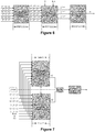
- Figure 6 shows schematically the identification of the faulty winding using the voltage differential method which uses the voltages and currents of the windings.
- phase-comparison voltage values and phase-comparison current values are obtained by comparing the voltages and currents of the windings, Step 2.2.1, as follows.
- Step 2.2.3 the determined winding-comparison excitation voltage values are compared, Step 2.2.3, so as to determine which of the windings is the location of the fault.
- the third processing block 28 is configured to carry out a third processing step, Step 3, of the fault location determination process to identify the location of the fault within the faulty winding.
- Step 3 A block diagram representative of the third processing block 28 is shown in Figure 7 .
- the third processing block 28 is configured to determine the location of the fault based on an equivalent circuit of the three-phase transformer 20 which represents voltage and current conditions in the windings, impedances of the windings, transformer magnetizing impedance, transformer leakage resistance, and transformer leakage reactance.
- the equivalent circuit further represents a phase to ground fault on the faulty winding (Case 1), or a phase to phase fault on the faulty winding (Case 2).
- the voltage and current conditions can be determined from the voltages and currents of the windings.
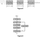
- Figures 8 and 9 illustrate the determination of the location of the fault within the faulty winding in the event of a phase to ground fault on the faulty winding.
- the fault location determination unit 22 is therefore capable of locating a fault in a plurality of windings of a three-phase transformer 20 by using voltages and currents measured at the terminals of the transformer 20 when the transformer 20 is in an online mode under the fault conditions.
- the fault location determination unit 22 may be configured for locating a fault in a pair of windings of a single-phase transformer 20. More particularly, such a fault location determination unit 22 is configured to determine the location of the fault based on an equivalent circuit of the single-phase transformer 20 which represents voltage and current conditions in the windings, impedances of the windings, and transformer 20 magnetizing impedance.
- the equivalent circuit further represents an inter-turn fault on one of the windings, a winding to winding fault, or a winding to winding to ground fault.
- the voltage and current conditions can be determined from the voltages and currents of the windings.
- Figure 10 shows schematically the single-phase transformer 20 with the inter-turn fault on one of its windings, where the inter-turn fault is a winding to ground fault with a fault resistance R g .
- the location of the inter-turn fault within the faulty winding corresponds to a fraction x of the length of the faulty winding from the top end of the faulty winding.
- Figure 11 shows the equivalent circuit of the single-phase transformer 20 of Figure 10 .
- the voltages U 1 , U 2 and currents I 1 , I 2 of the windings are calculated from the measured voltages and currents at the terminals of the single-phase transformer 20.
- the above equation can be solved to obtain the values of the variables x, R g and i f , where i f is the fault current in the winding to ground fault.
- Figure 12 shows schematically the single-phase transformer 20 with the winding to winding fault.
- the location of the winding to winding fault corresponds to a fraction x of the length of each winding from the top end of each winding.
- Figure 13 shows the equivalent circuit of the single-phase transformer 20 of Figure 12 .
- the voltages U 1 , U 2 and currents I 1 , I 2 of the windings are calculated from the measured voltages and currents at the terminals of the single-phase transformer 20.
- the above equation can be solved to obtain the values of the variables x,, i f and Uf. In this case the fault current i f flows between the two windings.
- Figure 14 shows schematically the single-phase transformer 20 with the winding to winding to ground fault.
- the location of the winding to winding to ground fault corresponds to a fraction x of the length of each winding from the top end of each winding.
- Figure 15 shows the equivalent circuit of the single-phase transformer 20 of Figure 14 .
- the voltages U 1 , U 2 and currents I 1 , I 2 of the windings are calculated from the measured voltages and currents at the terminals of the single-phase transformer 20.
- the above equation can be solved to obtain the values of the variables x,, i f1 , i f2 and U f .
- each of the fault currents i f1 , i f2 flow to ground from each of the primary and secondary windings respectively.
- the fault location determination unit 22 is therefore capable of locating a fault in a plurality of windings of a single-phase transformer 20 by using voltages and currents measured at the terminals of the transformer 20 when the transformer 20 is in an online mode under the fault conditions.
- a fault may include, for example, a pre-empt fault which is an initial intermittent high impedance short circuit fault preceding a severe short circuit fault
- the fault location determination unit 22 may be in the form of a computing device and the like, and may include one or more features of a computing device, such as processor, memory, display device.
Landscapes
- Engineering & Computer Science (AREA)
- Power Engineering (AREA)
- Physics & Mathematics (AREA)
- General Physics & Mathematics (AREA)
- Testing Of Short-Circuits, Discontinuities, Leakage, Or Incorrect Line Connections (AREA)
Priority Applications (1)
| Application Number | Priority Date | Filing Date | Title |
|---|---|---|---|
| EP18167372.4A EP3553539B1 (fr) | 2018-04-13 | 2018-04-13 | Appareil et procédé pour localiser un défaut dans une pluralité d'enroulements d'un transformateur |
Applications Claiming Priority (1)
| Application Number | Priority Date | Filing Date | Title |
|---|---|---|---|
| EP18167372.4A EP3553539B1 (fr) | 2018-04-13 | 2018-04-13 | Appareil et procédé pour localiser un défaut dans une pluralité d'enroulements d'un transformateur |
Publications (2)
| Publication Number | Publication Date |
|---|---|
| EP3553539A1 true EP3553539A1 (fr) | 2019-10-16 |
| EP3553539B1 EP3553539B1 (fr) | 2020-07-01 |
Family
ID=62002034
Family Applications (1)
| Application Number | Title | Priority Date | Filing Date |
|---|---|---|---|
| EP18167372.4A Active EP3553539B1 (fr) | 2018-04-13 | 2018-04-13 | Appareil et procédé pour localiser un défaut dans une pluralité d'enroulements d'un transformateur |
Country Status (1)
| Country | Link |
|---|---|
| EP (1) | EP3553539B1 (fr) |
Cited By (5)
| Publication number | Priority date | Publication date | Assignee | Title |
|---|---|---|---|---|
| ES2758531A1 (es) * | 2019-11-06 | 2020-05-05 | Univ Madrid Politecnica | Sistema y metodo de localizacion de faltas a tierra en instalaciones de corriente alterna |
| CN111913135A (zh) * | 2020-08-19 | 2020-11-10 | 中国海洋石油集团有限公司 | 一种利用牛顿迭代法辨识变压器绕组形变故障的方法 |
| CN112285616A (zh) * | 2020-09-24 | 2021-01-29 | 国网河北省电力有限公司 | 一种快速判断电气设备内部故障的方法及装置 |
| US11460517B2 (en) | 2019-06-25 | 2022-10-04 | General Electric Technology Gmbh | Systems, apparatus, and methods for locating a fault in a plurality of windings of a transformer |
| CN118191686A (zh) * | 2024-05-15 | 2024-06-14 | 广东电网有限责任公司广州供电局 | 变压器绕组变形检测方法、装置、存储介质及设备 |
Citations (7)
| Publication number | Priority date | Publication date | Assignee | Title |
|---|---|---|---|---|
| US20080300807A1 (en) * | 2004-03-23 | 2008-12-04 | The University Of British Columbia | Electric Winding Displacement Detection Method and Apparatus |
| US20090059447A1 (en) * | 2005-12-09 | 2009-03-05 | Abb Technology Ltd | Method and device for fault detection in an n-winding three-phase power transformer |
| US20120158325A1 (en) * | 2010-12-16 | 2012-06-21 | General Electric Company | Method and system for monitoring transformer health |
| EP2544322A1 (fr) * | 2011-07-05 | 2013-01-09 | ABB Technology AG | Procédé de choix entre les circuits internes et externes dans des lignes parallèles au moyen de mesures d'une extrémité |
| US20150204934A1 (en) * | 2012-07-23 | 2015-07-23 | Curtin University Of Technology | Method of determining a characteristic of a power transformer and a system therefor |
| US20170030958A1 (en) * | 2014-04-15 | 2017-02-02 | Abb Schweiz Ag | Transformer parameter estimation using terminal measurements |
| US20170227591A1 (en) * | 2016-02-10 | 2017-08-10 | General Electric Company | Systems and methods for detecting turn-to-turn faults in windings |
-
2018
- 2018-04-13 EP EP18167372.4A patent/EP3553539B1/fr active Active
Patent Citations (7)
| Publication number | Priority date | Publication date | Assignee | Title |
|---|---|---|---|---|
| US20080300807A1 (en) * | 2004-03-23 | 2008-12-04 | The University Of British Columbia | Electric Winding Displacement Detection Method and Apparatus |
| US20090059447A1 (en) * | 2005-12-09 | 2009-03-05 | Abb Technology Ltd | Method and device for fault detection in an n-winding three-phase power transformer |
| US20120158325A1 (en) * | 2010-12-16 | 2012-06-21 | General Electric Company | Method and system for monitoring transformer health |
| EP2544322A1 (fr) * | 2011-07-05 | 2013-01-09 | ABB Technology AG | Procédé de choix entre les circuits internes et externes dans des lignes parallèles au moyen de mesures d'une extrémité |
| US20150204934A1 (en) * | 2012-07-23 | 2015-07-23 | Curtin University Of Technology | Method of determining a characteristic of a power transformer and a system therefor |
| US20170030958A1 (en) * | 2014-04-15 | 2017-02-02 | Abb Schweiz Ag | Transformer parameter estimation using terminal measurements |
| US20170227591A1 (en) * | 2016-02-10 | 2017-08-10 | General Electric Company | Systems and methods for detecting turn-to-turn faults in windings |
Cited By (6)
| Publication number | Priority date | Publication date | Assignee | Title |
|---|---|---|---|---|
| US11460517B2 (en) | 2019-06-25 | 2022-10-04 | General Electric Technology Gmbh | Systems, apparatus, and methods for locating a fault in a plurality of windings of a transformer |
| ES2758531A1 (es) * | 2019-11-06 | 2020-05-05 | Univ Madrid Politecnica | Sistema y metodo de localizacion de faltas a tierra en instalaciones de corriente alterna |
| CN111913135A (zh) * | 2020-08-19 | 2020-11-10 | 中国海洋石油集团有限公司 | 一种利用牛顿迭代法辨识变压器绕组形变故障的方法 |
| CN112285616A (zh) * | 2020-09-24 | 2021-01-29 | 国网河北省电力有限公司 | 一种快速判断电气设备内部故障的方法及装置 |
| CN112285616B (zh) * | 2020-09-24 | 2022-05-06 | 国网河北省电力有限公司 | 一种快速判断电气设备内部故障的方法及装置 |
| CN118191686A (zh) * | 2024-05-15 | 2024-06-14 | 广东电网有限责任公司广州供电局 | 变压器绕组变形检测方法、装置、存储介质及设备 |
Also Published As
| Publication number | Publication date |
|---|---|
| EP3553539B1 (fr) | 2020-07-01 |
Similar Documents
| Publication | Publication Date | Title |
|---|---|---|
| EP3553539B1 (fr) | Appareil et procédé pour localiser un défaut dans une pluralité d'enroulements d'un transformateur | |
| EP3069426B1 (fr) | Procédé et appareil de protection tour-à-tour de réacteur | |
| RU2540851C2 (ru) | Способ выбора короткозамкнутой фазы и определения типа короткого замыкания | |
| RU2571629C1 (ru) | Способ и устройство для оценки угла напряжения нулевой последовательности при однофазном замыкании на землю | |
| US11885843B2 (en) | Method, system and apparatus for fault detection | |
| WO1995024014A2 (fr) | Systeme de localisation d'un defaut a partir des donnees d'un seul terminal | |
| EP4270702A1 (fr) | Procédé de détection d'un défaut dans une ligne de transmission d'un système de transmission de puissance | |
| CN107658860B (zh) | 配电网系统故障抑制方法及装置、计算机存储介质及设备 | |
| CN110546881A (zh) | 用于电气系统中的故障检测的负序电压的分段估计 | |
| CN112946558A (zh) | 一种专变用户计量异常监测方法及系统 | |
| Patel et al. | A novel approach to transformer differential protection using sequence component based algorithm | |
| JP7490078B2 (ja) | 送電システムにおける障害検出 | |
| JP2020076671A (ja) | 対地静電容量測定装置および対地静電容量測定方法 | |
| US10707677B2 (en) | Differential protection method and differential protection device for a transformer | |
| CN105242135A (zh) | 三相电力变压器参数在线辨识装置及其实现算法 | |
| CN103543315A (zh) | 一种500kV自耦变压器短路电流的阻抗网络分析方法 | |
| EP3588107B1 (fr) | Procédé et dispositif de calcul des courants d'enroulement du cote delta d'un transformateur | |
| US11460517B2 (en) | Systems, apparatus, and methods for locating a fault in a plurality of windings of a transformer | |
| CN113872153B (zh) | 一种基于主变六角图测试纵向矢量合成方法 | |
| CN121079857A (zh) | 检测在ac电力传输系统中的传输线路中的故障的方法 | |
| Venikar et al. | Transformer incipient inter-turn fault detection based on no-load current harmonic analysis | |
| Bertrand et al. | A simulation model for transformer internal faults base for the study of protection and monitoring systems | |
| CN109884471A (zh) | 相量积有功法判断故障相及选线方法 | |
| CN111537911B (zh) | 一种基于零序阻抗的电抗器匝间短路故障识别方法及系统 | |
| EP3141918B1 (fr) | Améliorations apportées ou se rapportant à la détermination d'un emplacement défectueux dans un milieu de transmission de puissance |
Legal Events
| Date | Code | Title | Description |
|---|---|---|---|
| PUAI | Public reference made under article 153(3) epc to a published international application that has entered the european phase |
Free format text: ORIGINAL CODE: 0009012 |
|
| STAA | Information on the status of an ep patent application or granted ep patent |
Free format text: STATUS: THE APPLICATION HAS BEEN PUBLISHED |
|
| AK | Designated contracting states |
Kind code of ref document: A1 Designated state(s): AL AT BE BG CH CY CZ DE DK EE ES FI FR GB GR HR HU IE IS IT LI LT LU LV MC MK MT NL NO PL PT RO RS SE SI SK SM TR |
|
| AX | Request for extension of the european patent |
Extension state: BA ME |
|
| STAA | Information on the status of an ep patent application or granted ep patent |
Free format text: STATUS: REQUEST FOR EXAMINATION WAS MADE |
|
| 17P | Request for examination filed |
Effective date: 20191125 |
|
| RBV | Designated contracting states (corrected) |
Designated state(s): AL AT BE BG CH CY CZ DE DK EE ES FI FR GB GR HR HU IE IS IT LI LT LU LV MC MK MT NL NO PL PT RO RS SE SI SK SM TR |
|
| GRAP | Despatch of communication of intention to grant a patent |
Free format text: ORIGINAL CODE: EPIDOSNIGR1 |
|
| STAA | Information on the status of an ep patent application or granted ep patent |
Free format text: STATUS: GRANT OF PATENT IS INTENDED |
|
| REG | Reference to a national code |
Ref country code: DE Ref legal event code: R079 Ref document number: 602018005630 Country of ref document: DE Free format text: PREVIOUS MAIN CLASS: G01R0031020000 Ipc: G01R0031500000 |
|
| INTG | Intention to grant announced |
Effective date: 20200123 |
|
| RIC1 | Information provided on ipc code assigned before grant |
Ipc: G01R 31/62 20200101ALI20200129BHEP Ipc: G01R 31/50 20200101AFI20200129BHEP Ipc: G01R 31/72 20200101ALI20200129BHEP |
|
| GRAS | Grant fee paid |
Free format text: ORIGINAL CODE: EPIDOSNIGR3 |
|
| GRAA | (expected) grant |
Free format text: ORIGINAL CODE: 0009210 |
|
| STAA | Information on the status of an ep patent application or granted ep patent |
Free format text: STATUS: THE PATENT HAS BEEN GRANTED |
|
| AK | Designated contracting states |
Kind code of ref document: B1 Designated state(s): AL AT BE BG CH CY CZ DE DK EE ES FI FR GB GR HR HU IE IS IT LI LT LU LV MC MK MT NL NO PL PT RO RS SE SI SK SM TR |
|
| REG | Reference to a national code |
Ref country code: CH Ref legal event code: EP Ref country code: AT Ref legal event code: REF Ref document number: 1286665 Country of ref document: AT Kind code of ref document: T Effective date: 20200715 |
|
| REG | Reference to a national code |
Ref country code: IE Ref legal event code: FG4D |
|
| REG | Reference to a national code |
Ref country code: DE Ref legal event code: R096 Ref document number: 602018005630 Country of ref document: DE |
|
| REG | Reference to a national code |
Ref country code: SE Ref legal event code: TRGR |
|
| REG | Reference to a national code |
Ref country code: LT Ref legal event code: MG4D |
|
| PG25 | Lapsed in a contracting state [announced via postgrant information from national office to epo] |
Ref country code: BG Free format text: LAPSE BECAUSE OF FAILURE TO SUBMIT A TRANSLATION OF THE DESCRIPTION OR TO PAY THE FEE WITHIN THE PRESCRIBED TIME-LIMIT Effective date: 20201001 |
|
| REG | Reference to a national code |
Ref country code: NL Ref legal event code: MP Effective date: 20200701 |
|
| REG | Reference to a national code |
Ref country code: AT Ref legal event code: MK05 Ref document number: 1286665 Country of ref document: AT Kind code of ref document: T Effective date: 20200701 |
|
| PG25 | Lapsed in a contracting state [announced via postgrant information from national office to epo] |
Ref country code: LT Free format text: LAPSE BECAUSE OF FAILURE TO SUBMIT A TRANSLATION OF THE DESCRIPTION OR TO PAY THE FEE WITHIN THE PRESCRIBED TIME-LIMIT Effective date: 20200701 Ref country code: CZ Free format text: LAPSE BECAUSE OF FAILURE TO SUBMIT A TRANSLATION OF THE DESCRIPTION OR TO PAY THE FEE WITHIN THE PRESCRIBED TIME-LIMIT Effective date: 20200701 Ref country code: PT Free format text: LAPSE BECAUSE OF FAILURE TO SUBMIT A TRANSLATION OF THE DESCRIPTION OR TO PAY THE FEE WITHIN THE PRESCRIBED TIME-LIMIT Effective date: 20201102 Ref country code: GR Free format text: LAPSE BECAUSE OF FAILURE TO SUBMIT A TRANSLATION OF THE DESCRIPTION OR TO PAY THE FEE WITHIN THE PRESCRIBED TIME-LIMIT Effective date: 20201002 Ref country code: NO Free format text: LAPSE BECAUSE OF FAILURE TO SUBMIT A TRANSLATION OF THE DESCRIPTION OR TO PAY THE FEE WITHIN THE PRESCRIBED TIME-LIMIT Effective date: 20201001 Ref country code: ES Free format text: LAPSE BECAUSE OF FAILURE TO SUBMIT A TRANSLATION OF THE DESCRIPTION OR TO PAY THE FEE WITHIN THE PRESCRIBED TIME-LIMIT Effective date: 20200701 Ref country code: AT Free format text: LAPSE BECAUSE OF FAILURE TO SUBMIT A TRANSLATION OF THE DESCRIPTION OR TO PAY THE FEE WITHIN THE PRESCRIBED TIME-LIMIT Effective date: 20200701 Ref country code: HR Free format text: LAPSE BECAUSE OF FAILURE TO SUBMIT A TRANSLATION OF THE DESCRIPTION OR TO PAY THE FEE WITHIN THE PRESCRIBED TIME-LIMIT Effective date: 20200701 Ref country code: FI Free format text: LAPSE BECAUSE OF FAILURE TO SUBMIT A TRANSLATION OF THE DESCRIPTION OR TO PAY THE FEE WITHIN THE PRESCRIBED TIME-LIMIT Effective date: 20200701 |
|
| PG25 | Lapsed in a contracting state [announced via postgrant information from national office to epo] |
Ref country code: RS Free format text: LAPSE BECAUSE OF FAILURE TO SUBMIT A TRANSLATION OF THE DESCRIPTION OR TO PAY THE FEE WITHIN THE PRESCRIBED TIME-LIMIT Effective date: 20200701 Ref country code: LV Free format text: LAPSE BECAUSE OF FAILURE TO SUBMIT A TRANSLATION OF THE DESCRIPTION OR TO PAY THE FEE WITHIN THE PRESCRIBED TIME-LIMIT Effective date: 20200701 Ref country code: PL Free format text: LAPSE BECAUSE OF FAILURE TO SUBMIT A TRANSLATION OF THE DESCRIPTION OR TO PAY THE FEE WITHIN THE PRESCRIBED TIME-LIMIT Effective date: 20200701 Ref country code: IS Free format text: LAPSE BECAUSE OF FAILURE TO SUBMIT A TRANSLATION OF THE DESCRIPTION OR TO PAY THE FEE WITHIN THE PRESCRIBED TIME-LIMIT Effective date: 20201101 |
|
| PG25 | Lapsed in a contracting state [announced via postgrant information from national office to epo] |
Ref country code: NL Free format text: LAPSE BECAUSE OF FAILURE TO SUBMIT A TRANSLATION OF THE DESCRIPTION OR TO PAY THE FEE WITHIN THE PRESCRIBED TIME-LIMIT Effective date: 20200701 |
|
| REG | Reference to a national code |
Ref country code: DE Ref legal event code: R097 Ref document number: 602018005630 Country of ref document: DE |
|
| PG25 | Lapsed in a contracting state [announced via postgrant information from national office to epo] |
Ref country code: SM Free format text: LAPSE BECAUSE OF FAILURE TO SUBMIT A TRANSLATION OF THE DESCRIPTION OR TO PAY THE FEE WITHIN THE PRESCRIBED TIME-LIMIT Effective date: 20200701 Ref country code: IT Free format text: LAPSE BECAUSE OF FAILURE TO SUBMIT A TRANSLATION OF THE DESCRIPTION OR TO PAY THE FEE WITHIN THE PRESCRIBED TIME-LIMIT Effective date: 20200701 Ref country code: DK Free format text: LAPSE BECAUSE OF FAILURE TO SUBMIT A TRANSLATION OF THE DESCRIPTION OR TO PAY THE FEE WITHIN THE PRESCRIBED TIME-LIMIT Effective date: 20200701 Ref country code: RO Free format text: LAPSE BECAUSE OF FAILURE TO SUBMIT A TRANSLATION OF THE DESCRIPTION OR TO PAY THE FEE WITHIN THE PRESCRIBED TIME-LIMIT Effective date: 20200701 Ref country code: EE Free format text: LAPSE BECAUSE OF FAILURE TO SUBMIT A TRANSLATION OF THE DESCRIPTION OR TO PAY THE FEE WITHIN THE PRESCRIBED TIME-LIMIT Effective date: 20200701 |
|
| PLBE | No opposition filed within time limit |
Free format text: ORIGINAL CODE: 0009261 |
|
| STAA | Information on the status of an ep patent application or granted ep patent |
Free format text: STATUS: NO OPPOSITION FILED WITHIN TIME LIMIT |
|
| PG25 | Lapsed in a contracting state [announced via postgrant information from national office to epo] |
Ref country code: AL Free format text: LAPSE BECAUSE OF FAILURE TO SUBMIT A TRANSLATION OF THE DESCRIPTION OR TO PAY THE FEE WITHIN THE PRESCRIBED TIME-LIMIT Effective date: 20200701 |
|
| 26N | No opposition filed |
Effective date: 20210406 |
|
| PG25 | Lapsed in a contracting state [announced via postgrant information from national office to epo] |
Ref country code: SK Free format text: LAPSE BECAUSE OF FAILURE TO SUBMIT A TRANSLATION OF THE DESCRIPTION OR TO PAY THE FEE WITHIN THE PRESCRIBED TIME-LIMIT Effective date: 20200701 |
|
| PG25 | Lapsed in a contracting state [announced via postgrant information from national office to epo] |
Ref country code: SI Free format text: LAPSE BECAUSE OF FAILURE TO SUBMIT A TRANSLATION OF THE DESCRIPTION OR TO PAY THE FEE WITHIN THE PRESCRIBED TIME-LIMIT Effective date: 20200701 |
|
| PG25 | Lapsed in a contracting state [announced via postgrant information from national office to epo] |
Ref country code: MC Free format text: LAPSE BECAUSE OF FAILURE TO SUBMIT A TRANSLATION OF THE DESCRIPTION OR TO PAY THE FEE WITHIN THE PRESCRIBED TIME-LIMIT Effective date: 20200701 |
|
| PG25 | Lapsed in a contracting state [announced via postgrant information from national office to epo] |
Ref country code: LU Free format text: LAPSE BECAUSE OF NON-PAYMENT OF DUE FEES Effective date: 20210413 |
|
| REG | Reference to a national code |
Ref country code: BE Ref legal event code: MM Effective date: 20210430 |
|
| PG25 | Lapsed in a contracting state [announced via postgrant information from national office to epo] |
Ref country code: LI Free format text: LAPSE BECAUSE OF NON-PAYMENT OF DUE FEES Effective date: 20210430 Ref country code: CH Free format text: LAPSE BECAUSE OF NON-PAYMENT OF DUE FEES Effective date: 20210430 |
|
| PG25 | Lapsed in a contracting state [announced via postgrant information from national office to epo] |
Ref country code: IE Free format text: LAPSE BECAUSE OF NON-PAYMENT OF DUE FEES Effective date: 20210413 |
|
| PG25 | Lapsed in a contracting state [announced via postgrant information from national office to epo] |
Ref country code: IS Free format text: LAPSE BECAUSE OF FAILURE TO SUBMIT A TRANSLATION OF THE DESCRIPTION OR TO PAY THE FEE WITHIN THE PRESCRIBED TIME-LIMIT Effective date: 20201101 |
|
| PG25 | Lapsed in a contracting state [announced via postgrant information from national office to epo] |
Ref country code: BE Free format text: LAPSE BECAUSE OF NON-PAYMENT OF DUE FEES Effective date: 20210430 |
|
| P01 | Opt-out of the competence of the unified patent court (upc) registered |
Effective date: 20230522 |
|
| PG25 | Lapsed in a contracting state [announced via postgrant information from national office to epo] |
Ref country code: CY Free format text: LAPSE BECAUSE OF FAILURE TO SUBMIT A TRANSLATION OF THE DESCRIPTION OR TO PAY THE FEE WITHIN THE PRESCRIBED TIME-LIMIT Effective date: 20200701 |
|
| PG25 | Lapsed in a contracting state [announced via postgrant information from national office to epo] |
Ref country code: HU Free format text: LAPSE BECAUSE OF FAILURE TO SUBMIT A TRANSLATION OF THE DESCRIPTION OR TO PAY THE FEE WITHIN THE PRESCRIBED TIME-LIMIT; INVALID AB INITIO Effective date: 20180413 |
|
| PG25 | Lapsed in a contracting state [announced via postgrant information from national office to epo] |
Ref country code: MK Free format text: LAPSE BECAUSE OF FAILURE TO SUBMIT A TRANSLATION OF THE DESCRIPTION OR TO PAY THE FEE WITHIN THE PRESCRIBED TIME-LIMIT Effective date: 20200701 |
|
| PG25 | Lapsed in a contracting state [announced via postgrant information from national office to epo] |
Ref country code: MT Free format text: LAPSE BECAUSE OF FAILURE TO SUBMIT A TRANSLATION OF THE DESCRIPTION OR TO PAY THE FEE WITHIN THE PRESCRIBED TIME-LIMIT Effective date: 20200701 |
|
| PGFP | Annual fee paid to national office [announced via postgrant information from national office to epo] |
Ref country code: SE Payment date: 20250319 Year of fee payment: 8 |
|
| PGFP | Annual fee paid to national office [announced via postgrant information from national office to epo] |
Ref country code: FR Payment date: 20250319 Year of fee payment: 8 |
|
| PGFP | Annual fee paid to national office [announced via postgrant information from national office to epo] |
Ref country code: GB Payment date: 20250319 Year of fee payment: 8 |
|
| PGFP | Annual fee paid to national office [announced via postgrant information from national office to epo] |
Ref country code: DE Payment date: 20250319 Year of fee payment: 8 |
|
| PG25 | Lapsed in a contracting state [announced via postgrant information from national office to epo] |
Ref country code: TR Free format text: LAPSE BECAUSE OF FAILURE TO SUBMIT A TRANSLATION OF THE DESCRIPTION OR TO PAY THE FEE WITHIN THE PRESCRIBED TIME-LIMIT Effective date: 20200701 |