EP3553513B1 - Acoustic emission sensor holder - Google Patents
Acoustic emission sensor holder Download PDFInfo
- Publication number
- EP3553513B1 EP3553513B1 EP19159741.8A EP19159741A EP3553513B1 EP 3553513 B1 EP3553513 B1 EP 3553513B1 EP 19159741 A EP19159741 A EP 19159741A EP 3553513 B1 EP3553513 B1 EP 3553513B1
- Authority
- EP
- European Patent Office
- Prior art keywords
- holder
- tubular body
- sensor
- acoustic emission
- metallic
- Prior art date
- Legal status (The legal status is an assumption and is not a legal conclusion. Google has not performed a legal analysis and makes no representation as to the accuracy of the status listed.)
- Active
Links
Images


Classifications
-
- G—PHYSICS
- G01—MEASURING; TESTING
- G01N—INVESTIGATING OR ANALYSING MATERIALS BY DETERMINING THEIR CHEMICAL OR PHYSICAL PROPERTIES
- G01N29/00—Investigating or analysing materials by the use of ultrasonic, sonic or infrasonic waves; Visualisation of the interior of objects by transmitting ultrasonic or sonic waves through the object
- G01N29/22—Details, e.g. general constructional or apparatus details
- G01N29/223—Supports, positioning or alignment in fixed situation
-
- B—PERFORMING OPERATIONS; TRANSPORTING
- B23—MACHINE TOOLS; METAL-WORKING NOT OTHERWISE PROVIDED FOR
- B23P—METAL-WORKING NOT OTHERWISE PROVIDED FOR; COMBINED OPERATIONS; UNIVERSAL MACHINE TOOLS
- B23P19/00—Machines for simply fitting together or separating metal parts or objects, or metal and non-metal parts, whether or not involving some deformation; Tools or devices therefor so far as not provided for in other classes
-
- F—MECHANICAL ENGINEERING; LIGHTING; HEATING; WEAPONS; BLASTING
- F16—ENGINEERING ELEMENTS AND UNITS; GENERAL MEASURES FOR PRODUCING AND MAINTAINING EFFECTIVE FUNCTIONING OF MACHINES OR INSTALLATIONS; THERMAL INSULATION IN GENERAL
- F16M—FRAMES, CASINGS OR BEDS OF ENGINES, MACHINES OR APPARATUS, NOT SPECIFIC TO ENGINES, MACHINES OR APPARATUS PROVIDED FOR ELSEWHERE; STANDS; SUPPORTS
- F16M13/00—Other supports for positioning apparatus or articles; Means for steadying hand-held apparatus or articles
- F16M13/02—Other supports for positioning apparatus or articles; Means for steadying hand-held apparatus or articles for supporting on, or attaching to, an object, e.g. tree, gate, window-frame, cycle
-
- G—PHYSICS
- G01—MEASURING; TESTING
- G01N—INVESTIGATING OR ANALYSING MATERIALS BY DETERMINING THEIR CHEMICAL OR PHYSICAL PROPERTIES
- G01N29/00—Investigating or analysing materials by the use of ultrasonic, sonic or infrasonic waves; Visualisation of the interior of objects by transmitting ultrasonic or sonic waves through the object
- G01N29/04—Analysing solids
-
- G—PHYSICS
- G01—MEASURING; TESTING
- G01N—INVESTIGATING OR ANALYSING MATERIALS BY DETERMINING THEIR CHEMICAL OR PHYSICAL PROPERTIES
- G01N29/00—Investigating or analysing materials by the use of ultrasonic, sonic or infrasonic waves; Visualisation of the interior of objects by transmitting ultrasonic or sonic waves through the object
- G01N29/14—Investigating or analysing materials by the use of ultrasonic, sonic or infrasonic waves; Visualisation of the interior of objects by transmitting ultrasonic or sonic waves through the object using acoustic emission techniques
-
- G—PHYSICS
- G01—MEASURING; TESTING
- G01N—INVESTIGATING OR ANALYSING MATERIALS BY DETERMINING THEIR CHEMICAL OR PHYSICAL PROPERTIES
- G01N29/00—Investigating or analysing materials by the use of ultrasonic, sonic or infrasonic waves; Visualisation of the interior of objects by transmitting ultrasonic or sonic waves through the object
- G01N29/22—Details, e.g. general constructional or apparatus details
- G01N29/26—Arrangements for orientation or scanning by relative movement of the head and the sensor
-
- G—PHYSICS
- G10—MUSICAL INSTRUMENTS; ACOUSTICS
- G10K—SOUND-PRODUCING DEVICES; METHODS OR DEVICES FOR PROTECTING AGAINST, OR FOR DAMPING, NOISE OR OTHER ACOUSTIC WAVES IN GENERAL; ACOUSTICS NOT OTHERWISE PROVIDED FOR
- G10K11/00—Methods or devices for transmitting, conducting or directing sound in general; Methods or devices for protecting against, or for damping, noise or other acoustic waves in general
- G10K11/004—Mounting transducers, e.g. provided with mechanical moving or orienting device
-
- H—ELECTRICITY
- H10—SEMICONDUCTOR DEVICES; ELECTRIC SOLID-STATE DEVICES NOT OTHERWISE PROVIDED FOR
- H10N—ELECTRIC SOLID-STATE DEVICES NOT OTHERWISE PROVIDED FOR
- H10N30/00—Piezoelectric or electrostrictive devices
- H10N30/80—Constructional details
- H10N30/88—Mounts; Supports; Enclosures; Casings
-
- G—PHYSICS
- G01—MEASURING; TESTING
- G01N—INVESTIGATING OR ANALYSING MATERIALS BY DETERMINING THEIR CHEMICAL OR PHYSICAL PROPERTIES
- G01N2291/00—Indexing codes associated with group G01N29/00
- G01N2291/02—Indexing codes associated with the analysed material
- G01N2291/023—Solids
- G01N2291/0231—Composite or layered materials
-
- G—PHYSICS
- G01—MEASURING; TESTING
- G01N—INVESTIGATING OR ANALYSING MATERIALS BY DETERMINING THEIR CHEMICAL OR PHYSICAL PROPERTIES
- G01N2291/00—Indexing codes associated with group G01N29/00
- G01N2291/02—Indexing codes associated with the analysed material
- G01N2291/023—Solids
- G01N2291/0232—Glass, ceramics, concrete or stone
-
- G—PHYSICS
- G01—MEASURING; TESTING
- G01N—INVESTIGATING OR ANALYSING MATERIALS BY DETERMINING THEIR CHEMICAL OR PHYSICAL PROPERTIES
- G01N2291/00—Indexing codes associated with group G01N29/00
- G01N2291/02—Indexing codes associated with the analysed material
- G01N2291/025—Change of phase or condition
- G01N2291/0258—Structural degradation, e.g. fatigue of composites, ageing of oils
-
- G—PHYSICS
- G01—MEASURING; TESTING
- G01N—INVESTIGATING OR ANALYSING MATERIALS BY DETERMINING THEIR CHEMICAL OR PHYSICAL PROPERTIES
- G01N2291/00—Indexing codes associated with group G01N29/00
- G01N2291/10—Number of transducers
- G01N2291/101—Number of transducers one transducer
-
- G—PHYSICS
- G01—MEASURING; TESTING
- G01N—INVESTIGATING OR ANALYSING MATERIALS BY DETERMINING THEIR CHEMICAL OR PHYSICAL PROPERTIES
- G01N2291/00—Indexing codes associated with group G01N29/00
- G01N2291/10—Number of transducers
- G01N2291/106—Number of transducers one or more transducer arrays
-
- G—PHYSICS
- G01—MEASURING; TESTING
- G01N—INVESTIGATING OR ANALYSING MATERIALS BY DETERMINING THEIR CHEMICAL OR PHYSICAL PROPERTIES
- G01N2291/00—Indexing codes associated with group G01N29/00
- G01N2291/26—Scanned objects
- G01N2291/263—Surfaces
- G01N2291/2632—Surfaces flat
-
- G—PHYSICS
- G01—MEASURING; TESTING
- G01N—INVESTIGATING OR ANALYSING MATERIALS BY DETERMINING THEIR CHEMICAL OR PHYSICAL PROPERTIES
- G01N2291/00—Indexing codes associated with group G01N29/00
- G01N2291/26—Scanned objects
- G01N2291/263—Surfaces
- G01N2291/2634—Surfaces cylindrical from outside
-
- G—PHYSICS
- G01—MEASURING; TESTING
- G01N—INVESTIGATING OR ANALYSING MATERIALS BY DETERMINING THEIR CHEMICAL OR PHYSICAL PROPERTIES
- G01N2291/00—Indexing codes associated with group G01N29/00
- G01N2291/26—Scanned objects
- G01N2291/263—Surfaces
- G01N2291/2638—Complex surfaces
-
- G—PHYSICS
- G01—MEASURING; TESTING
- G01N—INVESTIGATING OR ANALYSING MATERIALS BY DETERMINING THEIR CHEMICAL OR PHYSICAL PROPERTIES
- G01N2291/00—Indexing codes associated with group G01N29/00
- G01N2291/26—Scanned objects
- G01N2291/269—Various geometry objects
- G01N2291/2694—Wings or other aircraft parts
Definitions
- This disclosure generally relates to holders for maintaining the positioning and surface contact of sensors on an article during testing, and more particularly to acoustic emission sensor holders for use during environmental testing of non-metallic and non-magnetic materials, such as composite or ceramic materials.
- Environmental conditions may affect materials used to make vehicles and other types of structures intended for outdoor use or for use in extreme environments, such as aerospace structures that experience dynamic and various environmental changes throughout their service history (i.e., dry to wet, cold to hot).
- Environmental testing of such materials at less than -17.78 °C (0°F) and greater than 37.78°C (100°F), and from 0-100% humidity, is desired to identify, quantify and monitor the properties of such materials before, during and/or after one or more uses to determine if any damage to the materials has occurred.
- acoustic emission interprets the radiation of acoustic (or elastic) waves in solid materials into usable AE waveforms that help understand how the materials behave.
- acoustic (or elastic) waves occur when a material undergoes changes in its internal structure, for example as a result of crack formation or plastic deformation due to aging, temperature gradients or external mechanical forces.
- the waves generated by sources of acoustic emission are of practical interest in the fields of structural health monitoring, quality control, system feedback, process monitoring, analysis validation, and others, and may be used to detect, locate and characterize damage to the material.
- Acoustic emission sensors are therefore useful for detecting flaws and failures in materials and structures, and determining how to apply remedial solutions and repairs to resolve structural issues.
- acoustic emission sensing has been identified as a technology that can be scaled for enhanced fleet inspection from the laboratory setting, to the depot and to field applications. The focus is driven by the need to identify the existence of damage as a function of service hours for the fleet in order to make critical decisions regarding remaining life.
- Acoustic emission sensors have been used to monitor aerospace and other structures.
- Traditional approaches for attaching acoustic emission sensors to the structure to be tested include using hot glue or magnetic clamping fixtures.
- Many commercially available holders for acoustic emission sensors are magnetic because acoustic emission has predominantly been done on metallic surfaces. Such magnetic holders will not function with non-metallic and non-magnetic composite materials.
- Hot glue does not have universal application, and does not work during environmental testing at temperatures less than -53.89°C (-65°F) and greater than 71,11°C (160°F) due to poor surface adhesion.
- Non-metallic and non-magnetic materials such as composite materials
- composite materials have become widely used to manufacture aerospace structures and component parts for aerospace structures such as aircraft ribs, spars, panels, fuselages, wings, wing boxes, fuel tanks, tail assemblies and other component parts of an aircraft because they are lightweight and strong, and therefore provide fuel economy and other benefits.
- the traditional approaches for attaching acoustic emission sensors to such non-metallic and non-magnetic materials are not effective.
- EP 0 403 807 A2 states, according to its abstract, a non-destructive non-invasive arrangement is provided for detecting defects, such as voids, or poorly adhering layers in solid objects and laminated materials.
- a sensing signal is emitted by one transducer and received by two others. All of the sensors are disposed in a housing unit. The difference between the received signals is used to indicate a defect in the work piece proximate one of the transducers.
- US 7,546,780 B2 states, according to its abstract, a mounting device configured for mounting a sensing device in relation to a supporting structure, and related method of mounting, are disclosed.
- the mounting device includes a first support component capable of being mounted at least indirectly in relation to the supporting structure, a second support component configured to support the sensing device, and a connecting component coupled between the first and second support components, where the connecting component supports the second support component in relation to the first support component.
- the mounting device includes an adjustor coupled to at least one of the first support component, the second support component and the connecting component that influences a positioning of the second support component in relation to the first support component.
- the mounting device includes a first housing portion having a first appendage, and a second housing portion having a second appendage, where the second housing portion is slidable in relation to the first housing portion.
- the mounting device further includes an actuating portion capable of causing sliding movement between the housing portions, where the sensing device is supported within at least one of the housing portions, hi some embodiments, a rotatable swivel ball on which the sensing device is sup-ported is contained within at least one of the housing portions, and actuation of the actuating portion results in both the coupling of the mounting device to a supporting structure and a setting of a position of the swivel ball.
- an acoustic emission sensor holder that aligns and maintains the acoustic emission sensor flush with a surface of a non-metallic and non-magnetic material and is compatible with current ASTM standard test methods and test fixtures.
- the sensor holder provides the capability of keeping the sensor in contact with the material during extreme conditions, and therefore provides a pathway to obtain data across a wide range of environmental conditions that will be advantageous in progressive damage structural analysis, field inspection, material characterization and laboratory level experimental validation.
- a holder for attaching an acoustic emission sensor to a non-metallic and non-magnetic material is disclosed.
- the holder is comprised of a tubular body having a closed top end and an open bottom end through which the sensor may be inserted into the tubular body.
- the closed top end is provided with a plurality of unitary flexible flaps angularly extending inwardly from an inner surface of the closed top end.
- An inner surface of the tubular body has a plurality of partial cylindrically-shaped spacers extending radially inward and upward from the open bottom end of the tubular body.
- the unitary flexible flaps and the spacers act together to fix the sensor within the tubular body and maintain its positioning within the holder.
- the unitary flexible flaps and the spacers are made from a flexible material so that the holder can accommodate sensors of varying heights and diameters.
- acoustic emission sensor holders that maintain the positioning and contact of acoustic emission sensors during environmental testing (less than -17.78 °C (0°F), greater than 37.78°C (100°F), and between 0-100 % humidity) of non-metallic and non-magnetic materials including, but not limited to, composite or ceramic materials, are described with reference to aerospace structures to illustrate the general principles in the present disclosure. It will be recognized by one skilled in the art that the present disclosure may be practiced in other analogous applications or environments and/or with other analogous or equivalent variations of the illustrative aspects.
- the disclosed acoustic emission sensor holders may be used for environmental testing of any type of non-metallic and non-magnetic materials in any industry and may be used with non-metallic and non-magnetic materials of varying shapes, sizes and surface contours including test materials for environmental testing in laboratory or other controlled settings, and completed structures that employ such non-metallic and non-magnetic materials, such as aerospace structures and vehicles, and any other structures for which environmental testing would be beneficial.
- Such environmental testing may be done during manufacture of the structures, after manufacture of the structures or during use of the structures. It should be noted that those methods, procedures, components, or functions which are commonly known to persons of ordinary skill in the field of the disclosure are not described in detail herein.
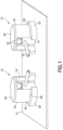
- an acoustic emission sensor holder 10 in accordance with one aspect of the disclosure is shown affixed to a non-metallic and non-magnetic material 12 in the form of a test article or coupon ( FIG. 1 ).
- the holder 10 has an acoustic emission sensor 14 installed therein with a sensor wire 16 (or electrical connection) protruding radially from the sensor 14 for connection to acoustic emission monitoring equipment (not shown).
- the holder 10 aligns a bottom surface 15 of the sensor 14 flush with a surface of the non-metallic and non-magnetic material 12 and permits use of current ASTM standard test methods and test equipment.
- the holder 10 is in the shape of a tubular body 18 having a closed top end 20 and an open bottom end 22 that forms an interface surface 24 having an aperture 25 at the open bottom end 22 of the tubular body 18.
- the sensor 14 is insertable into the tubular body 18 through the aperture 25.
- a recess 19 in the tubular body 18 is peripherally open toward the aperture 25 at the open bottom end 22 for receiving the sensor wire 16 (or electrical connection) that protrudes radially from the sensor 14, and may form a rectangular shape as shown or any other shape.
- the tubular body 18 also has a base 26 forming a lip 28 on top of the base 26 and peripherally around an exterior surface 30 of the tubular body 18 that expands the size of the interface surface 24 at the open bottom end 22 to provide sufficient surface area for sealant tape (described below).
- the closed top end 20 has a plurality of unitary flexible flaps 32 extending angularly inwardly from an inner surface 34 of the closed top end 20.
- two of the unitary flexible flaps 32 are shown, each extending angularly inwardly toward each other to provide a force to push down on a top surface of the sensor 14 when the sensor 14 is installed into the holder 10.
- An interior surface 36 of the tubular body 18 has a plurality of spacers 38 extending radially inward proximate the open bottom end 22.
- the unitary flexible flaps 32 and the spacers 38 act together to fix the sensor 14 within the tubular body 18, and may be formed in any shape and size that provides the ability to fix the sensor 14 within the tubular body 18.
- the spacers 38 may be formed in a partial cylindrical-shape protruding from the interior surface 36 of the tubular body 18 and extending upward from the open bottom end 22 as shown in the drawings, or the spacers 38 may be formed in a partial spherical-shape, oval-shape, or rectangular shape.
- the holder 10 may also be formed to have a cross-sectional shape that is square, rectangular or another curved shape to accommodate different shaped sensors 14.
- the holder 10 is formed with a flexible material as a unitary three-dimensional (3-D) printed structure.
- 3-D printing also known as stereolithography or additive manufacturing, is a printing technology that uses computer-controlled lasers to build three-dimensional structures from liquid polymers and other materials.
- the holders 10 disclosed herein are made from a flexible material. Because the unitary flexible flaps 32 at the closed top end 20 of the tubular body 18 and the spacers 38 are made from a flexible material, the holder 10 can accommodate sensors 14 of varying heights and diameters.
- the flexible material that forms the holder 10 and its parts should be ductile or flexible enough that the unitary flexible flaps 32 can bend but not snap when the sensor 14 is placed into the holder 10, and should have some stiffness to provide the downward force on the sensor 14.
- the flexible material should also be lightweight and have a wide range of operating temperatures to withstand environmental testing conditions, such as composite testing temperatures in the range from about -51.11°C (-60°F) to 65.56°C (150°F).
- a flexible material having properties in the ranges shown in Table I could be used to form the holders described in the present disclosure: TABLE I - MATERIAL PROPERTIES Flexural Modulus 2.1 to 7.6 GPa (0.3 to 1.1 ⁇ 10 6 psi) Flexural Strength 72 to 97 MPa (10 to 14 ⁇ 10 3 psi) Strength to Weight Ratio 37 to 79 kN m/kg Tensile Strength: Ultimate (UTS) 37 to 110 MPa (5.4 to 16 ⁇ 10 3 psi) Melting Temperature Around 186.11°C (385°F) Embrittlement -168°C
- Embrittlement is the temperature at which the material losses ductility, making it brittle.
- the melting temperature and embrittlement properties may be adjusted depending on the environmental conditions being tested.
- One material that has these properties and may be 3-D printed is ABS (Acrylonitrile-Butadiene-Styrene).
- ABS is a thermoplastic material further classified as styrenic plastic.
- the holder 10 is affixed to the non-metallic and non-magnetic material 12 using vacuum bag, sealant tape, or a permanent sealant, which may be positioned on the interface surface 24 at the open bottom end 22 of the tubular body 18.
- Vacuum bag or sealant tapes should be able to withstand environmental testing conditions, and have short (less than 5 minutes) adhering time.
- Suitable tapes for this purpose are commercially available, for example, the sealant tapes available from the Airtech Advanced Materials Group of Airtech International, Inc., Huntington Beach, California, under the trade names GS-95, AT-199, AIRSEAL 2, AIRSEAL 3W, AIRSEAL DB, GS-100, AT-200Y, GS-213, GS-213 Tacky, GS-333, GS-213-3, GS-43MR, VBS-750 and A-800-3G.
- sealant tapes are typically available in rolls and are easy to cut and position in desired locations.
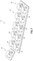
- FIGS. 4-7 An alternative holder 40 for attaching an acoustic emission sensor 14 to a non-metallic and non-magnetic material 12 and various systems 42, 44 using the alternative holder are shown in FIGS. 4-7 .
- the alternative holder 40 comprises two parts - a cage 46 and a retainer bracket 48 - removably enagagable with each other by rotating the cage 46 into and out of engagement with retainer bracket 48.
- the cage 46 and the retainer bracket 48 are each unitary 3-D printed structures using the flexible materials described above, and may be manufactured individually or in groups of alternative holders 40, as shown in FIG. 7 , to have a modular assemblage 41.
- the plurality of alternative holders 40 are retained together at a frange periphery 49 around each of the retainer brackets 48 in each of the alternative holders 40.
- the frange periphery 49 permits separation of adjacent alternative holders 40.
- Each alternative holder 40 may be readily separated from the other alternative holders 40 in the modular assemblage 41 by snapping them apart or using a knife or scissor to cut them apart.
- the modular assemblage 41 of alternative holders 40 shown in FIG. 7 may also be used as a group on a non-metallic and non-magnetic material 12 to provide minimum spacing between sensors 14.
- one or more the retainer brackets 48 may be affixed to a non-metallic and non-magnetic material 12 and a sensor 14 may be easily installed into or removed from the alternative holder 40 by simply rotating the cage 46 and removing it from the retainer bracket 48. This permits sensors 14 to be replaced while maintaining the positioning and configuration of the retainer brackets 48 (and thus the sensors 14) on the non-metallic and non-magnetic material 12. There is no need to remove the retainer bracket 48 from the non-metallic and non-magnetic material 12.
- the cage 46 of the alternative holder 40 has a similar configuration to the holder 10 with a tubular body 18 having a closed top end 20 and an open bottom end 22 through which the sensor 14 is inserted into the tubular body 18.
- the closed top end 20 of the tubular body 18 has a plurality of unitary flexible flaps 32 angularly extending inwardly from an inner surface 34 of the closed top end 20, and an interior surface 36 of the tubular body 18 has a plurality of partial cylindrically-shaped spacers 38 extending radially inward and upward from the open bottom end 22 of the tubular body 18, for fixing the sensor 14 within the tubular body 18.
- FIGS. 1-3 FIGS.
- each of the unitary flexible flaps 32 extending angularly inwardly toward each other to provide a downward force onto a top surface of the sensor 14 when the sensor is installed into the alternative holder 40.
- the exterior surface 30 of the tubular body 18 near the open bottom end 22 of the cage 46 of the alternative holder 40 has a different configuration than that shown in the holder 10.
- the cage 46 in the alternative holder 40 has a plurality of capture tabs 50 extending outwardly from the exterior surface 30 of the tubular body 18 to provide a generally flat surface 52 in a plane generally perpendicular to the plane of the tubular body 18 proximate the open bottom end 22.
- the capture tabs 50 are used to removably engage the cage 46 to the retainer bracket 48.
- FIG. 4 shows three capture tabs 50 positioned around the exterior surface 30 of the tubular body 18, but any number can be used depending on the diameter of the cage 46.
- the retainer bracket 48 has a lower surface 54 for attachment to the non-metallic and non-magnetic material 12, a top capture surface 56 and an engagement keyway 58 disposed between the lower surface 54 and the capture surface 56 in an aperture 60 through the retainer bracket 48.
- the plurality of capture tabs 50 of the cage 46 are slidably engagable with the engagement keyway 58 in the retainer bracket 48 in a rotary motion (in the direction shown by arrow A in FIG. 4 ) to provide a removable locking engagement between the cage 46 and the retainer bracket 48.
- a stop may be provided in the engagement keyway 58 to provide notice to the user that the cage 46 is locked into the retainer bracket 48.
- the cage 46 may be configured to snap into the retainer bracket 48 without rotating, and provide removal by squeezing the sides of the tubular body 18 or other means for removing a snap-fitted part.
- the lower surface 54 of the retainer bracket has the form of an attach pad or leg.
- a sealant tape as described above is adhered to the lower surface 54 of the retainer bracket 48 for affixing the alternative holder 40 to a non-metallic and non-magnetic material 12.
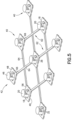
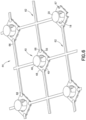
- the alternative holders 40 are separated from the modular assemblage 41 shown in FIG. 7 and arranged in an array with predetermined spacing.
- the predetermined spacing between each of the alternative holders 40 is provided by a separator 62 having a plurality of arms 64 positioned, for example, in an X-formation generally perpendicular to each other. Configurations other than X-formations may also be used, such as a straight separator without a crossing arm, or a separator configured to have a spider shape, a triangle, a circular pattern or a free-form pattern. Examples of such alternative patterns are shown in FIGS. 9A-9D .
- the shape, size and configuration options should be adaptive to the structural requirements.
- the repair patch when used for aerospace structures comprising a non-metallic and non-magnetic material 12, the repair patch is typically in the form of an ellipsoidal or circular geometry.
- the separators 62 could be configured to provide a network extending around the perimeter to bound the patch.
- the systems 42, 44 and variations thereof that are disclosed herein are readily adaptive to meet such structural needs.
- a long strip or rope of sensors as shown in FIG. 9D , may be provided to wrap along a wing, spar, rib, skin of an aircraft or any other type of surface, and be positioned in any desired configuration.
- Ends 66 of each of the arms 64 are engageable with a plurality of retainer brackets 48 for positioning a plurality of the alternative holders 40 on the non-metallic and non-magnetic material 12 with predetermined spacing therebetween.
- a plurality of separators 62 is used with a plurality of alternative holders 40 to make a wide variety of configurations for the array of alternative holders 40.
- the separators 62 comprise a flexible material (as described above) that permits positioning of the plurality of alternative holders 40 with predetermined spacing on flat surfaces, curved surfaces or surfaces of a non-metallic and non-magnetic material 12 with complex geometric shapes, and permits the entire configuration of sensors to actuate and move with the surface (for example, during fatigue loading, or during actual service use, or such that the entire configuration of sensors may be used between two parts that actuate with respect to each other)
- the separators 62 may be attached to the alternative holders 40 in any way known for attaching flexible materials together. For example, adhesives may be used, the ends 66 of the arms 64 can be configured to snap together or to mate together in other ways.
- FIG. 5 shows an aspect that uses an adhesive to affix the ends 66 of the arms 64 to corners of the frange periphery 49 of the retainer brackets 48.
- the system of FIG. 6 shows an aspect that uses a snap-fit attachment means where the corners of the retainer bracket 48 have a bulbous cutout 67 that accommodates a bulbous end 68 of the arms 64 of the separator 62.
- a plurality of alternative holders 40 are used with a plurality of separators 62 to form a sensor holder array that is affixed to a non-metallic and non-magnetic material 12, which may be a test article or a completed structure, before, during or after manufacture and use of such structure.
- an alternative holder 40 is separated from a plurality of alternative holders 40 that are retained together in a modular assemblage 41 at a frange periphery 49 around the retainer brackets 48 of each of the alternative holders 40.
- step 104 the retainer bracket 48 of the separated alternative holder is affixed to the non-metallic and non-magnetic material with a sealant tape as described above.
- step 106 the cage 46 of the alternative holder 40 is removed from the retainer bracket 48 by rotating the cage 46 out of the engagement keyway 58.
- a sensor 14, such as an acoustic emission sensor, is then inserted into the tubular body 18 of the cage 46 in step 108 and, in step 110, the cage 46 with the installed sensor 14 is engaged with the retainer bracket 48 by rotating the cage into the engagement keyway 58 in the direction shown by the arrow A in FIG. 4 .
- the step 103 may be added to create an array of sensor holders with predetermined spacing between each sensor holder.
- the retainer bracket 48 of one of the alternative holders 40 is engaged with one end 66 of a separator 62 having a plurality of arms 64 positioned in an X-formation, and the retainer bracket 48 of another of the alternative holders 40 is engaged at another end 66 of the separator 62.
- the array of alternative holders 40 with predetermined spacing is then affixed to the non-metallic and non-magnetic material 12 in step 104.
- a kit may be provided that includes a plurality of alternative holders 40 connected together in a modular assemblage 41, at least one separator 62 and sealant tape.
- the holders and separators disclosed herein provide a cost and time efficient system and method for affixing sensors, such as acoustic emission sensors, to a non-metallic and non-magnetic material.
- the holders do not require additional assembly such as springs and screws, and the systems are scalable to account for variations in sensor size and test configurations, and may be used in a wide range of temperature conditions suitable for environmental testing at testing scales ranging from test article or coupon level to complete structures, such as aircraft, and any testing condition, from laboratory to field/depot, thus providing acoustic emission data from diverse environmental conditions.
- the geometry of the sensor holder 10 and the cage 46 and retainer bracket 48 of the alternative sensor holder 40 may be designed to conform to the size and geometry of any type of acoustic sensor 14.
- the retainer bracket 48 may be fabricated and unitized in any modular assembly to provide different group assemblages, the separator lengths may be altered to form any array shape or geometry to cover targeted structural areas with higher or lower density of sensor placement.
- the adherent (such as vacuum tape etc.) may be pre-applied to the retainer bracket 48 on an individual or on a group basis and sealed so as to preserve the tacky/sticky end for adhering to a surface of a non-metallic and non-magnetic material 12.
- This aspect would be provided as a pre-packaged kit containing all required parts for rapid use.
- the arms 64 of the separators 62 may be designed so as to snap, clip, press, into place into the retainer bracket 48.
- the retainer bracket 48 and cage 46 could be a monolithic/1-piece construction to reduce the number of parts for a specific acoustic sensor type/geometry.
- the width and geometry of the separator 62 may be further designed to provide non-symmetric configurations of any network or array geometry (such as spider-web, circular, triangular, diamond, linear, or curved as shown in FIGS. 9A-9D , or any other configuration).
- Such non-symmetric configurations may be designed to cover a desired structural geometry/configuration (e.g. to cover the surface area of a doubler, the perimeter of a known damage region, or boundaries of a repair patch), with a mix of cages 46 and retainer brackets 48 available to create a network of multiple sensor sizes.
- the separator 62 and retainer bracket 48 may also be formed as a monolithic/1-piece unit.
Landscapes
- Physics & Mathematics (AREA)
- General Physics & Mathematics (AREA)
- Pathology (AREA)
- Life Sciences & Earth Sciences (AREA)
- Chemical & Material Sciences (AREA)
- Analytical Chemistry (AREA)
- Biochemistry (AREA)
- General Health & Medical Sciences (AREA)
- Health & Medical Sciences (AREA)
- Immunology (AREA)
- Acoustics & Sound (AREA)
- Engineering & Computer Science (AREA)
- Mechanical Engineering (AREA)
- General Engineering & Computer Science (AREA)
- Multimedia (AREA)
- Investigating Or Analyzing Materials By The Use Of Ultrasonic Waves (AREA)
- Geophysics And Detection Of Objects (AREA)
- Investigating Or Analyzing Materials By The Use Of Magnetic Means (AREA)
- Measurement Of Mechanical Vibrations Or Ultrasonic Waves (AREA)
Description
- This disclosure generally relates to holders for maintaining the positioning and surface contact of sensors on an article during testing, and more particularly to acoustic emission sensor holders for use during environmental testing of non-metallic and non-magnetic materials, such as composite or ceramic materials.
- Environmental conditions may affect materials used to make vehicles and other types of structures intended for outdoor use or for use in extreme environments, such as aerospace structures that experience dynamic and various environmental changes throughout their service history (i.e., dry to wet, cold to hot). Environmental testing of such materials at less than -17.78 °C (0°F) and greater than 37.78°C (100°F), and from 0-100% humidity, is desired to identify, quantify and monitor the properties of such materials before, during and/or after one or more uses to determine if any damage to the materials has occurred.
- One type of sensor that has been used for environmental testing, acoustic emission (or AE) sensors, interprets the radiation of acoustic (or elastic) waves in solid materials into usable AE waveforms that help understand how the materials behave. Such acoustic (or elastic) waves occur when a material undergoes changes in its internal structure, for example as a result of crack formation or plastic deformation due to aging, temperature gradients or external mechanical forces. The waves generated by sources of acoustic emission are of practical interest in the fields of structural health monitoring, quality control, system feedback, process monitoring, analysis validation, and others, and may be used to detect, locate and characterize damage to the material. Acoustic emission sensors are therefore useful for detecting flaws and failures in materials and structures, and determining how to apply remedial solutions and repairs to resolve structural issues. In the aerospace field, acoustic emission sensing has been identified as a technology that can be scaled for enhanced fleet inspection from the laboratory setting, to the depot and to field applications. The focus is driven by the need to identify the existence of damage as a function of service hours for the fleet in order to make critical decisions regarding remaining life.
- Acoustic emission sensors have been used to monitor aerospace and other structures. Traditional approaches for attaching acoustic emission sensors to the structure to be tested include using hot glue or magnetic clamping fixtures. Many commercially available holders for acoustic emission sensors are magnetic because acoustic emission has predominantly been done on metallic surfaces. Such magnetic holders will not function with non-metallic and non-magnetic composite materials. Hot glue does not have universal application, and does not work during environmental testing at temperatures less than -53.89°C (-65°F) and greater than 71,11°C (160°F) due to poor surface adhesion. Another solution has been to permanently attach acoustic emission sensors to a test article, but this approach is not feasible when testing large numbers of test articles due to expense and extended dwell time (greater than 10 hours per sensor) for curing an adhesive to affix the sensors to the test article.
- Non-metallic and non-magnetic materials, such as composite materials, are now used in the manufacture of a wide variety of structures due to their high strength and rigidity, low weight, corrosion resistance and other favorable properties. For example, composite materials have become widely used to manufacture aerospace structures and component parts for aerospace structures such as aircraft ribs, spars, panels, fuselages, wings, wing boxes, fuel tanks, tail assemblies and other component parts of an aircraft because they are lightweight and strong, and therefore provide fuel economy and other benefits. The traditional approaches for attaching acoustic emission sensors to such non-metallic and non-magnetic materials are not effective.
- Accordingly, there is a need for improved means for holding or attaching acoustic emission sensors to non-metallic and non-magnetic materials, such as composites and ceramics, during environmental testing of such materials that provide advantages over known acoustic emission sensor holders.
-
EP 0 403 807 A2 states, according to its abstract, a non-destructive non-invasive arrangement is provided for detecting defects, such as voids, or poorly adhering layers in solid objects and laminated materials. A sensing signal is emitted by one transducer and received by two others. All of the sensors are disposed in a housing unit. The difference between the received signals is used to indicate a defect in the work piece proximate one of the transducers.US 7,546,780 B2 states, according to its abstract, a mounting device configured for mounting a sensing device in relation to a supporting structure, and related method of mounting, are disclosed. In at least some embodiments, the mounting device includes a first support component capable of being mounted at least indirectly in relation to the supporting structure, a second support component configured to support the sensing device, and a connecting component coupled between the first and second support components, where the connecting component supports the second support component in relation to the first support component. Also, the mounting device includes an adjustor coupled to at least one of the first support component, the second support component and the connecting component that influences a positioning of the second support component in relation to the first support component.US 2007/0074582 A1 states, according to its abstract, a mounting device for supporting a sensing device in relation to a supporting structure, and related method of installing a sensing device, are disclosed. In at least some embodiments, the mounting device includes a first housing portion having a first appendage, and a second housing portion having a second appendage, where the second housing portion is slidable in relation to the first housing portion. The mounting device further includes an actuating portion capable of causing sliding movement between the housing portions, where the sensing device is supported within at least one of the housing portions, hi some embodiments, a rotatable swivel ball on which the sensing device is sup-ported is contained within at least one of the housing portions, and actuation of the actuating portion results in both the coupling of the mounting device to a supporting structure and a setting of a position of the swivel ball. - According to the present disclosure, a holder as defined in the independent claim 1 is provided. Further embodiments of the invention are defined in the dependent claims. Although the invention is only defined by the claims, the below embodiments, examples, and aspects are present for aiding in understanding the background and advantages of the invention.
- The foregoing purposes, as well as others, are achieved by an acoustic emission sensor holder that aligns and maintains the acoustic emission sensor flush with a surface of a non-metallic and non-magnetic material and is compatible with current ASTM standard test methods and test fixtures. The sensor holder provides the capability of keeping the sensor in contact with the material during extreme conditions, and therefore provides a pathway to obtain data across a wide range of environmental conditions that will be advantageous in progressive damage structural analysis, field inspection, material characterization and laboratory level experimental validation.
- In accordance with one aspect of the product of the disclosure, a holder for attaching an acoustic emission sensor to a non-metallic and non-magnetic material is disclosed. The holder is comprised of a tubular body having a closed top end and an open bottom end through which the sensor may be inserted into the tubular body. The closed top end is provided with a plurality of unitary flexible flaps angularly extending inwardly from an inner surface of the closed top end. An inner surface of the tubular body has a plurality of partial cylindrically-shaped spacers extending radially inward and upward from the open bottom end of the tubular body. The unitary flexible flaps and the spacers act together to fix the sensor within the tubular body and maintain its positioning within the holder. The unitary flexible flaps and the spacers are made from a flexible material so that the holder can accommodate sensors of varying heights and diameters.
- Other objects, features, and advantages of the various embodiments in the present disclosure will be explained in the following detailed description with reference to the appended drawings.
-
-
FIG. 1 is an illustration of a non-metallic and non-magnetic material having acoustic emission sensor holders and sensors affixed thereto prepared for environmental testing. -
FIG. 2 is an illustration of a bottom, front and right side perspective view of an acoustic emission sensor holder with an acoustic emission sensor therein. -
FIG. 3 is an illustration of another perspective view of the acoustic emission sensor holder shown inFIG. 2 . -
FIG. 4 is an illustration of another aspect of an acoustic emission sensor holder. -
FIG. 5 is an illustration of an arrangement of a plurality of the acoustic emission sensor holder shown inFIG. 4 as part of a system of the disclosure. -
FIG. 6 is an illustration of another aspect of an acoustic emission sensor holder. -
FIG. 7 is an illustration of a plurality of acoustic emission sensor holders as shown inFIG. 4 in a removable snap-fit configuration as part of a system of the disclosure. -
FIG. 8 is a block diagram of a method of the disclosure. -
FIGS. 9A-9D are illustrations of alternative arrangements for a plurality of the acoustic emission sensor holders of this disclosure. - In the following detailed description, various aspects of acoustic emission sensor holders that maintain the positioning and contact of acoustic emission sensors during environmental testing (less than -17.78 °C (0°F), greater than 37.78°C (100°F), and between 0-100 % humidity) of non-metallic and non-magnetic materials including, but not limited to, composite or ceramic materials, are described with reference to aerospace structures to illustrate the general principles in the present disclosure. It will be recognized by one skilled in the art that the present disclosure may be practiced in other analogous applications or environments and/or with other analogous or equivalent variations of the illustrative aspects. For example, the disclosed acoustic emission sensor holders may be used for environmental testing of any type of non-metallic and non-magnetic materials in any industry and may be used with non-metallic and non-magnetic materials of varying shapes, sizes and surface contours including test materials for environmental testing in laboratory or other controlled settings, and completed structures that employ such non-metallic and non-magnetic materials, such as aerospace structures and vehicles, and any other structures for which environmental testing would be beneficial. Such environmental testing may be done during manufacture of the structures, after manufacture of the structures or during use of the structures. It should be noted that those methods, procedures, components, or functions which are commonly known to persons of ordinary skill in the field of the disclosure are not described in detail herein.
- In
FIGS. 1-3 , an acousticemission sensor holder 10 in accordance with one aspect of the disclosure is shown affixed to a non-metallic andnon-magnetic material 12 in the form of a test article or coupon (FIG. 1 ). Theholder 10 has anacoustic emission sensor 14 installed therein with a sensor wire 16 (or electrical connection) protruding radially from thesensor 14 for connection to acoustic emission monitoring equipment (not shown). Theholder 10 aligns abottom surface 15 of thesensor 14 flush with a surface of the non-metallic andnon-magnetic material 12 and permits use of current ASTM standard test methods and test equipment. - The
holder 10 is in the shape of atubular body 18 having a closedtop end 20 and anopen bottom end 22 that forms aninterface surface 24 having anaperture 25 at theopen bottom end 22 of thetubular body 18. Thesensor 14 is insertable into thetubular body 18 through theaperture 25. Arecess 19 in thetubular body 18 is peripherally open toward theaperture 25 at the openbottom end 22 for receiving the sensor wire 16 (or electrical connection) that protrudes radially from thesensor 14, and may form a rectangular shape as shown or any other shape. Thetubular body 18 also has a base 26 forming alip 28 on top of thebase 26 and peripherally around anexterior surface 30 of thetubular body 18 that expands the size of theinterface surface 24 at the openbottom end 22 to provide sufficient surface area for sealant tape (described below). - The closed
top end 20 has a plurality of unitaryflexible flaps 32 extending angularly inwardly from aninner surface 34 of the closedtop end 20. Here, two of the unitaryflexible flaps 32 are shown, each extending angularly inwardly toward each other to provide a force to push down on a top surface of thesensor 14 when thesensor 14 is installed into theholder 10. Aninterior surface 36 of thetubular body 18 has a plurality ofspacers 38 extending radially inward proximate the openbottom end 22. The unitaryflexible flaps 32 and thespacers 38 act together to fix thesensor 14 within thetubular body 18, and may be formed in any shape and size that provides the ability to fix thesensor 14 within thetubular body 18. For example, thespacers 38 may be formed in a partial cylindrical-shape protruding from theinterior surface 36 of thetubular body 18 and extending upward from the openbottom end 22 as shown in the drawings, or thespacers 38 may be formed in a partial spherical-shape, oval-shape, or rectangular shape. In addition to the round cross-sectional shape of thetubular body 18 as shown, theholder 10 may also be formed to have a cross-sectional shape that is square, rectangular or another curved shape to accommodate different shapedsensors 14. - The
holder 10 is formed with a flexible material as a unitary three-dimensional (3-D) printed structure. 3-D printing, also known as stereolithography or additive manufacturing, is a printing technology that uses computer-controlled lasers to build three-dimensional structures from liquid polymers and other materials. Theholders 10 disclosed herein are made from a flexible material. Because the unitaryflexible flaps 32 at the closedtop end 20 of thetubular body 18 and thespacers 38 are made from a flexible material, theholder 10 can accommodatesensors 14 of varying heights and diameters. - The flexible material that forms the
holder 10 and its parts should be ductile or flexible enough that the unitaryflexible flaps 32 can bend but not snap when thesensor 14 is placed into theholder 10, and should have some stiffness to provide the downward force on thesensor 14. The flexible material should also be lightweight and have a wide range of operating temperatures to withstand environmental testing conditions, such as composite testing temperatures in the range from about -51.11°C (-60°F) to 65.56°C (150°F). A flexible material having properties in the ranges shown in Table I could be used to form the holders described in the present disclosure:TABLE I - MATERIAL PROPERTIES Flexural Modulus 2.1 to 7.6 GPa (0.3 to 1.1 × 10⁶ psi) Flexural Strength 72 to 97 MPa (10 to 14 × 103 psi) Strength to Weight Ratio 37 to 79 kN m/kg Tensile Strength: Ultimate (UTS) 37 to 110 MPa (5.4 to 16 × 103 psi) Melting Temperature Around 186.11°C (385°F) Embrittlement -168°C - Embrittlement is the temperature at which the material losses ductility, making it brittle. The melting temperature and embrittlement properties may be adjusted depending on the environmental conditions being tested. One material that has these properties and may be 3-D printed is ABS (Acrylonitrile-Butadiene-Styrene). ABS is a thermoplastic material further classified as styrenic plastic.
- The
holder 10 is affixed to the non-metallic andnon-magnetic material 12 using vacuum bag, sealant tape, or a permanent sealant, which may be positioned on theinterface surface 24 at the openbottom end 22 of thetubular body 18. Vacuum bag or sealant tapes should be able to withstand environmental testing conditions, and have short (less than 5 minutes) adhering time. Suitable tapes for this purpose are commercially available, for example, the sealant tapes available from the Airtech Advanced Materials Group of Airtech International, Inc., Huntington Beach, California, under the trade names GS-95, AT-199, AIRSEAL 2, AIRSEAL 3W, AIRSEAL DB, GS-100, AT-200Y, GS-213, GS-213 Tacky, GS-333, GS-213-3, GS-43MR, VBS-750 and A-800-3G. Such sealant tapes are typically available in rolls and are easy to cut and position in desired locations. When affixing theholder 10 to the non-metallic andnon-magnetic material 12, it is also beneficial to apply vacuum grease or another coupling agent between thesensor 14 and the surface of the non-metallic andnon-magnetic material 12 to couple the acoustic energy between the non-metallic andnon-magnetic material 12 and thesensor 14 or more closely match the acoustic impedance of the disparate materials (e.g. to remove the air boundary by using a coupling agent). - An
alternative holder 40 for attaching anacoustic emission sensor 14 to a non-metallic andnon-magnetic material 12 andvarious systems FIGS. 4-7 . Thealternative holder 40 comprises two parts - acage 46 and a retainer bracket 48 - removably enagagable with each other by rotating thecage 46 into and out of engagement withretainer bracket 48. Thecage 46 and theretainer bracket 48 are each unitary 3-D printed structures using the flexible materials described above, and may be manufactured individually or in groups ofalternative holders 40, as shown inFIG. 7 , to have amodular assemblage 41. In themodular assemblage 41, the plurality ofalternative holders 40 are retained together at afrange periphery 49 around each of theretainer brackets 48 in each of thealternative holders 40. Thefrange periphery 49 permits separation of adjacentalternative holders 40. Eachalternative holder 40 may be readily separated from the otheralternative holders 40 in themodular assemblage 41 by snapping them apart or using a knife or scissor to cut them apart. Themodular assemblage 41 ofalternative holders 40 shown inFIG. 7 may also be used as a group on a non-metallic andnon-magnetic material 12 to provide minimum spacing betweensensors 14. - In this configuration, one or more the
retainer brackets 48 may be affixed to a non-metallic andnon-magnetic material 12 and asensor 14 may be easily installed into or removed from thealternative holder 40 by simply rotating thecage 46 and removing it from theretainer bracket 48. This permitssensors 14 to be replaced while maintaining the positioning and configuration of the retainer brackets 48 (and thus the sensors 14) on the non-metallic andnon-magnetic material 12. There is no need to remove theretainer bracket 48 from the non-metallic andnon-magnetic material 12. - The
cage 46 of thealternative holder 40 has a similar configuration to theholder 10 with atubular body 18 having a closedtop end 20 and an openbottom end 22 through which thesensor 14 is inserted into thetubular body 18. The closedtop end 20 of thetubular body 18 has a plurality of unitaryflexible flaps 32 angularly extending inwardly from aninner surface 34 of the closedtop end 20, and aninterior surface 36 of thetubular body 18 has a plurality of partial cylindrically-shapedspacers 38 extending radially inward and upward from the openbottom end 22 of thetubular body 18, for fixing thesensor 14 within thetubular body 18. As in theholder 10 shown inFIGS. 1-3 ,FIGS. 4-7 show a closedtop end 20 with two of the unitaryflexible flaps 32, each of the unitaryflexible flaps 32 extending angularly inwardly toward each other to provide a downward force onto a top surface of thesensor 14 when the sensor is installed into thealternative holder 40. - The
exterior surface 30 of thetubular body 18 near the openbottom end 22 of thecage 46 of thealternative holder 40 has a different configuration than that shown in theholder 10. Instead of thebase 26, thecage 46 in thealternative holder 40 has a plurality ofcapture tabs 50 extending outwardly from theexterior surface 30 of thetubular body 18 to provide a generallyflat surface 52 in a plane generally perpendicular to the plane of thetubular body 18 proximate the openbottom end 22. Thecapture tabs 50 are used to removably engage thecage 46 to theretainer bracket 48.FIG. 4 shows threecapture tabs 50 positioned around theexterior surface 30 of thetubular body 18, but any number can be used depending on the diameter of thecage 46. - The
retainer bracket 48 has alower surface 54 for attachment to the non-metallic andnon-magnetic material 12, atop capture surface 56 and anengagement keyway 58 disposed between thelower surface 54 and thecapture surface 56 in anaperture 60 through theretainer bracket 48. The plurality ofcapture tabs 50 of thecage 46 are slidably engagable with theengagement keyway 58 in theretainer bracket 48 in a rotary motion (in the direction shown by arrow A inFIG. 4 ) to provide a removable locking engagement between thecage 46 and theretainer bracket 48. A stop may be provided in theengagement keyway 58 to provide notice to the user that thecage 46 is locked into theretainer bracket 48. In other aspects, thecage 46 may be configured to snap into theretainer bracket 48 without rotating, and provide removal by squeezing the sides of thetubular body 18 or other means for removing a snap-fitted part. - The
lower surface 54 of the retainer bracket has the form of an attach pad or leg. A sealant tape as described above is adhered to thelower surface 54 of theretainer bracket 48 for affixing thealternative holder 40 to a non-metallic andnon-magnetic material 12. - In the
systems FIGS. 5-6 thealternative holders 40 are separated from themodular assemblage 41 shown inFIG. 7 and arranged in an array with predetermined spacing. The predetermined spacing between each of thealternative holders 40 is provided by aseparator 62 having a plurality ofarms 64 positioned, for example, in an X-formation generally perpendicular to each other. Configurations other than X-formations may also be used, such as a straight separator without a crossing arm, or a separator configured to have a spider shape, a triangle, a circular pattern or a free-form pattern. Examples of such alternative patterns are shown inFIGS. 9A-9D . The shape, size and configuration options should be adaptive to the structural requirements. For example, when a repair patch is used for aerospace structures comprising a non-metallic andnon-magnetic material 12, the repair patch is typically in the form of an ellipsoidal or circular geometry. Theseparators 62 could be configured to provide a network extending around the perimeter to bound the patch. There are multiple array geometries that may be conceived wherein the density of sensors in a particular area may be adjusted based on structural need, which may be due to known damage morphology or size, structure features and geometry, or the need for quick modifications of the sensor network during use. Thesystems FIG. 9D , may be provided to wrap along a wing, spar, rib, skin of an aircraft or any other type of surface, and be positioned in any desired configuration. - Ends 66 of each of the
arms 64 are engageable with a plurality ofretainer brackets 48 for positioning a plurality of thealternative holders 40 on the non-metallic andnon-magnetic material 12 with predetermined spacing therebetween. A plurality ofseparators 62 is used with a plurality ofalternative holders 40 to make a wide variety of configurations for the array ofalternative holders 40. Theseparators 62 comprise a flexible material (as described above) that permits positioning of the plurality ofalternative holders 40 with predetermined spacing on flat surfaces, curved surfaces or surfaces of a non-metallic andnon-magnetic material 12 with complex geometric shapes, and permits the entire configuration of sensors to actuate and move with the surface (for example, during fatigue loading, or during actual service use, or such that the entire configuration of sensors may be used between two parts that actuate with respect to each other) Theseparators 62 may be attached to thealternative holders 40 in any way known for attaching flexible materials together. For example, adhesives may be used, the ends 66 of thearms 64 can be configured to snap together or to mate together in other ways. The system ofFIG. 5 shows an aspect that uses an adhesive to affix theends 66 of thearms 64 to corners of thefrange periphery 49 of theretainer brackets 48. The system ofFIG. 6 shows an aspect that uses a snap-fit attachment means where the corners of theretainer bracket 48 have abulbous cutout 67 that accommodates abulbous end 68 of thearms 64 of theseparator 62. - In a
method 100 for affixing acoustic emission sensors to a non-metallic and non-magnetic material, referring toFIG. 8 , a plurality ofalternative holders 40 are used with a plurality ofseparators 62 to form a sensor holder array that is affixed to a non-metallic andnon-magnetic material 12, which may be a test article or a completed structure, before, during or after manufacture and use of such structure. Instep 102 of the method, analternative holder 40 is separated from a plurality ofalternative holders 40 that are retained together in amodular assemblage 41 at afrange periphery 49 around theretainer brackets 48 of each of thealternative holders 40. Instep 104, theretainer bracket 48 of the separated alternative holder is affixed to the non-metallic and non-magnetic material with a sealant tape as described above. Instep 106, thecage 46 of thealternative holder 40 is removed from theretainer bracket 48 by rotating thecage 46 out of theengagement keyway 58. Asensor 14, such as an acoustic emission sensor, is then inserted into thetubular body 18 of thecage 46 instep 108 and, instep 110, thecage 46 with the installedsensor 14 is engaged with theretainer bracket 48 by rotating the cage into theengagement keyway 58 in the direction shown by the arrow A inFIG. 4 . - In a further aspect of the
method 100, thestep 103 may be added to create an array of sensor holders with predetermined spacing between each sensor holder. In step 103A, theretainer bracket 48 of one of thealternative holders 40 is engaged with oneend 66 of aseparator 62 having a plurality ofarms 64 positioned in an X-formation, and theretainer bracket 48 of another of thealternative holders 40 is engaged at anotherend 66 of theseparator 62. The array ofalternative holders 40 with predetermined spacing is then affixed to the non-metallic andnon-magnetic material 12 instep 104. - A kit may be provided that includes a plurality of
alternative holders 40 connected together in amodular assemblage 41, at least oneseparator 62 and sealant tape. - The holders and separators disclosed herein provide a cost and time efficient system and method for affixing sensors, such as acoustic emission sensors, to a non-metallic and non-magnetic material. The holders do not require additional assembly such as springs and screws, and the systems are scalable to account for variations in sensor size and test configurations, and may be used in a wide range of temperature conditions suitable for environmental testing at testing scales ranging from test article or coupon level to complete structures, such as aircraft, and any testing condition, from laboratory to field/depot, thus providing acoustic emission data from diverse environmental conditions.
- Many other modifications and variations may of course be devised given the above description of various aspects for implementing the principles in the present disclosure. For example, and without limitation, the geometry of the
sensor holder 10 and thecage 46 andretainer bracket 48 of thealternative sensor holder 40 may be designed to conform to the size and geometry of any type ofacoustic sensor 14. Theretainer bracket 48 may be fabricated and unitized in any modular assembly to provide different group assemblages, the separator lengths may be altered to form any array shape or geometry to cover targeted structural areas with higher or lower density of sensor placement. The adherent (such as vacuum tape etc.) may be pre-applied to theretainer bracket 48 on an individual or on a group basis and sealed so as to preserve the tacky/sticky end for adhering to a surface of a non-metallic andnon-magnetic material 12. - This aspect would be provided as a pre-packaged kit containing all required parts for rapid use. Thearms 64 of theseparators 62 may be designed so as to snap, clip, press, into place into theretainer bracket 48. In other aspects, theretainer bracket 48 andcage 46 could be a monolithic/1-piece construction to reduce the number of parts for a specific acoustic sensor type/geometry. The width and geometry of theseparator 62 may be further designed to provide non-symmetric configurations of any network or array geometry (such as spider-web, circular, triangular, diamond, linear, or curved as shown inFIGS. 9A-9D , or any other configuration). Such non-symmetric configurations may be designed to cover a desired structural geometry/configuration (e.g. to cover the surface area of a doubler, the perimeter of a known damage region, or boundaries of a repair patch), with a mix ofcages 46 andretainer brackets 48 available to create a network of multiple sensor sizes. Theseparator 62 andretainer bracket 48 may also be formed as a monolithic/1-piece unit.
Claims (8)
- A holder (10) for attaching an acoustic emission sensor (14) to a non-metallic and non-magnetic material, the holder (10) comprising a tubular body (18) having a closed top end (20) and an open bottom end (22) through which the acoustic emission sensor (14) is insertable into the tubular body (18), the closed top end (20) having a plurality of unitary flexible flaps (32) angularly extending inwardly from an inner surface (34) of the enclosed top end (20), an inner surface of the tubular body (18) having a plurality of spacers (38) extending radially inward proximate the bottom end (22) of the tubular body (18), the unitary flexible flaps (32) and the spacers (38) fixing the acoustic emission sensor (14) within the tubular body (18), wherein the holder (10) is formed with a flexible material as a unitary three-dimensional printed structure, wherein the unitary flexible flaps (32) and the spacers (38) are made from the flexible material so that the holder (10) can accommodate sensors (14) of varying heights and diameters.
- The holder (10) of claim 1, wherein the closed top end (20) has two of the unitary flexible flaps (32), each of the unitary flexible flaps (32) extending angularly inwardly toward each other to provide a downward force onto a top surface of the sensor (14) when the sensor (14) is installed into the holder (10).
- The holder (10) of claim 1 or 2, further comprising a recess (19) in the tubular body (18) that is peripherally open toward the open bottom end (22) for receiving an electrical connection that protrudes radially from the sensor (14).
- The holder (10) of any of claims 1 to 3, further comprising a base (26) forming a lip (28) peripherally around an exterior surface (30) of the tubular body (18) proximate the open bottom end (22) to provide an interface surface (24) for engaging the non-metallic and non-magnetic surface.
- The holder of claim 4, wherein the holder (10) is configured to be affixed to the non-metallic and non-magnetic material (12) using a vacuum bag, a sealant tape, or a permanent sealant which are positioned on the interface surface (24) at the open bottom end (22) of the tubular body (18).
- The holder of any of claims 1 to 5, wherein the flexible material has a flexural modulus between 2.1 to 7.6 GPa, a flexural strength between 72 to 97 MPa, a strength to weight ratio between 37 to 79 kN m/kg, an ultimate tensile strength between 37 to 110 MPa, a melting temperature around 196°C, and an embrittlement of -168°C.
- The holder of any of claims 1 to 6, wherein the flexible material is Acrylonitrile-Butadiene-Styrene, ABS.
- The holder of any of claims 1 to 7, wherein the spacers (38) are formed in a partial cylindrical-shape protruding from an interior surface (36) of the tubular body (18) and extending upward from the open bottom end (22).
Applications Claiming Priority (2)
| Application Number | Priority Date | Filing Date | Title |
|---|---|---|---|
| US15/246,654 US10119940B2 (en) | 2016-08-25 | 2016-08-25 | Acoustic emission sensor holder |
| EP17178629.6A EP3287779B1 (en) | 2016-08-25 | 2017-06-29 | Acoustic emission sensor holder |
Related Parent Applications (2)
| Application Number | Title | Priority Date | Filing Date |
|---|---|---|---|
| EP17178629.6A Division EP3287779B1 (en) | 2016-08-25 | 2017-06-29 | Acoustic emission sensor holder |
| EP17178629.6A Division-Into EP3287779B1 (en) | 2016-08-25 | 2017-06-29 | Acoustic emission sensor holder |
Publications (2)
| Publication Number | Publication Date |
|---|---|
| EP3553513A1 EP3553513A1 (en) | 2019-10-16 |
| EP3553513B1 true EP3553513B1 (en) | 2024-12-18 |
Family
ID=59258056
Family Applications (2)
| Application Number | Title | Priority Date | Filing Date |
|---|---|---|---|
| EP19159741.8A Active EP3553513B1 (en) | 2016-08-25 | 2017-06-29 | Acoustic emission sensor holder |
| EP17178629.6A Active EP3287779B1 (en) | 2016-08-25 | 2017-06-29 | Acoustic emission sensor holder |
Family Applications After (1)
| Application Number | Title | Priority Date | Filing Date |
|---|---|---|---|
| EP17178629.6A Active EP3287779B1 (en) | 2016-08-25 | 2017-06-29 | Acoustic emission sensor holder |
Country Status (7)
| Country | Link |
|---|---|
| US (1) | US10119940B2 (en) |
| EP (2) | EP3553513B1 (en) |
| JP (1) | JP7030441B2 (en) |
| CN (1) | CN107782793B (en) |
| BR (1) | BR102017018188B1 (en) |
| CA (1) | CA2971264C (en) |
| RU (1) | RU2746719C2 (en) |
Families Citing this family (14)
| Publication number | Priority date | Publication date | Assignee | Title |
|---|---|---|---|---|
| JP6527905B2 (en) * | 2017-05-17 | 2019-06-05 | 矢崎総業株式会社 | Contact spring holding jig for grease application |
| US11110520B2 (en) * | 2018-08-10 | 2021-09-07 | The Boeing Company | Fastener alignment systems, fastener alignment kits, and associated methods |
| CN110208668B (en) * | 2019-07-10 | 2021-07-20 | 国网上海市电力公司 | Optical fiber acoustic emission vibration sensor and partial discharge sensing system |
| US11944490B2 (en) * | 2019-07-19 | 2024-04-02 | General Electric Company | Neuromodulation energy application techniques |
| CN110261490A (en) * | 2019-07-25 | 2019-09-20 | 中国计量大学 | A kind of fixed device of easy magnetic acoustic emission sensor and its fixing means |
| US10914617B1 (en) * | 2019-07-29 | 2021-02-09 | Terumo Cardiovascular Systems Corporation | Flexible sensor mount for hard shell blood reservoir |
| US20210085415A1 (en) * | 2019-09-23 | 2021-03-25 | GE Precision Healthcare LLC | Methods and systems for an accessory holder |
| CN112762290B (en) * | 2020-12-31 | 2022-07-01 | 哈尔滨工业大学 | L-shaped acoustic emission sensor array clamp and test method for detecting gas leakage |
| CN112692388B (en) * | 2021-01-04 | 2022-10-25 | 张晓民 | Electric spark machining fixture for acoustic emission sensor |
| CN113120255B (en) * | 2021-04-30 | 2022-01-25 | 成都飞机工业(集团)有限责任公司 | Full quick-witted assembly fixture of integral type |
| EP4337950A4 (en) * | 2021-07-08 | 2024-12-18 | Delta Engineering Corporation | NON-DESTRUCTIVE TESTING OF COMPOSITE COMPONENTS |
| KR102812600B1 (en) * | 2022-02-16 | 2025-05-26 | 한국건설기계연구원 | System for automatically measuring the amount of wear in the transfer pipe in real time |
| CN115047078A (en) * | 2022-06-20 | 2022-09-13 | 武汉大学 | Fixing device of acoustic emission sensor |
| CN117450407B (en) * | 2023-11-01 | 2024-04-19 | 广州奥测医学科技有限公司 | Laboratory environment monitoring device and method |
Citations (3)
| Publication number | Priority date | Publication date | Assignee | Title |
|---|---|---|---|---|
| US6341523B2 (en) * | 1998-01-07 | 2002-01-29 | Donnelly Corporation | Rain sensor mount for use in a vehicle |
| US7607347B2 (en) * | 2006-03-07 | 2009-10-27 | Gems Sensors, Inc. | Fluid level detector |
| US9086386B1 (en) * | 2012-07-12 | 2015-07-21 | The Boeing Company | Sensor coupling apparatus |
Family Cites Families (41)
| Publication number | Priority date | Publication date | Assignee | Title |
|---|---|---|---|---|
| US3894205A (en) * | 1974-01-21 | 1975-07-08 | Gen Motors Corp | Lamp socket and panel assembly with grounding switch |
| ATE73235T1 (en) | 1987-12-22 | 1992-03-15 | Kistler Instrumente Ag | ACCELEROMETER. |
| US4858470A (en) | 1988-03-23 | 1989-08-22 | Ird Mechanalysis, Inc. | Vibration transducer mounting |
| JP2613654B2 (en) * | 1989-06-22 | 1997-05-28 | 矢吉 肥後 | Ultrasonic testing |
| US5094524A (en) * | 1990-03-19 | 1992-03-10 | Fuhr Patti W | Method of visual testing and related product |
| JP2518449Y2 (en) * | 1991-01-29 | 1996-11-27 | 三菱重工業株式会社 | Ultrasonic probe |
| US5542859A (en) * | 1994-11-16 | 1996-08-06 | Woods Industries, Inc. | Quick mount electrical wall socket |
| JPH08220076A (en) * | 1995-02-17 | 1996-08-30 | Toyo Electric Mfg Co Ltd | AE sensor device |
| US6134968A (en) | 1999-07-19 | 2000-10-24 | The Boeing Company | Portable acoustic impedance measurement system |
| US6761078B2 (en) | 2001-08-30 | 2004-07-13 | Daniel Industries, Inc. | Ultrasonic flowmeter transducer mount |
| DE102005005331A1 (en) | 2005-01-28 | 2006-08-03 | Valeo Schalter Und Sensoren Gmbh | Holder for ultrasound sensor of motor vehicle`s parking system, has retainer provided between sleeve-shaped body and sensor, and fixing sensor inside body in axial and radial direction, where retainer is formed as single piece |
| US7412900B2 (en) * | 2005-09-30 | 2008-08-19 | Rockwell Automation Technologies, Inc. | Sensor mounting structure with adjustable swivel ball and panel mounting mechanism |
| US7546780B2 (en) * | 2005-09-30 | 2009-06-16 | Rockwell Automation Technologies, Inc. | Sensor mounting structure allowing for adjustment of sensor position |
| DE502005001079D1 (en) * | 2005-11-18 | 2007-08-30 | Ems Chemie Ag | Reinforced polyamide molding compounds |
| JP5093201B2 (en) * | 2009-09-01 | 2012-12-12 | ブラザー工業株式会社 | Wear tester, wear test piece, and wear test method |
| US8001699B2 (en) * | 2009-09-23 | 2011-08-23 | Stephen Randall | Electronic key impressioning (EKI) device, method and program product |
| WO2011101913A1 (en) * | 2010-02-19 | 2011-08-25 | 三菱電機株式会社 | Fastener for mounting ultrasonic sensor module and method for fastening |
| DE102010013311A1 (en) * | 2010-03-29 | 2011-09-29 | Festo Ag & Co. Kg | Sensor fastening device and associated sensor arrangement |
| US8322217B2 (en) * | 2010-04-06 | 2012-12-04 | Varel Europe S.A.S. | Acoustic emission toughness testing for PDC, PCBN, or other hard or superhard material inserts |
| US9004964B2 (en) * | 2010-09-10 | 2015-04-14 | Joseph W Grez | Activation and deactivation assembly for an electric outboard motor |
| KR101202843B1 (en) * | 2010-11-22 | 2012-11-20 | 한국철도기술연구원 | high-capacity static press |
| CN202002914U (en) * | 2010-12-28 | 2011-10-05 | 中国石油天然气股份有限公司 | Acoustic emission sensor fixture for tank floor corrosion detection |
| CN202291795U (en) * | 2011-06-14 | 2012-07-04 | 深圳市鹏煜威科技有限公司 | Double-stroke welding device of copper-aluminium-post resistance welding machine |
| CN202713115U (en) * | 2012-05-09 | 2013-01-30 | 林贵生 | Passive permanent magnet coupling transmission, braking or load device |
| US20140001234A1 (en) * | 2012-06-28 | 2014-01-02 | Ethicon Endo-Surgery, Inc. | Coupling arrangements for attaching surgical end effectors to drive systems therefor |
| RU2521748C1 (en) * | 2013-01-16 | 2014-07-10 | Открытое акционерное общество "Объединенные электротехнические заводы" (ОАО "ЭЛТЕЗА") | Control method of physical state of reinforced-concrete supports with stressed reinforcement bars |
| BR112014032424A2 (en) * | 2013-01-23 | 2017-06-27 | Eaton Corp | locking differential mounting and locking differential system |
| US8801453B1 (en) * | 2013-02-21 | 2014-08-12 | Bourns, Inc. | Rotary connector having a housing and a locking ring |
| DE102013101732A1 (en) * | 2013-02-21 | 2014-08-21 | Epcos Ag | sensor system |
| US20160038105A1 (en) * | 2013-03-15 | 2016-02-11 | Zuma Dental, LLC | Imaging system and method |
| JP6245496B2 (en) | 2013-05-23 | 2017-12-13 | パナソニックIpマネジメント株式会社 | Ultrasonic sensor device and mounting method thereof |
| US9453537B2 (en) * | 2013-10-31 | 2016-09-27 | Deere & Company | Coupler assembly |
| KR20150089657A (en) * | 2014-01-28 | 2015-08-05 | 김웅식 | sprinkler of plunger integral |
| USD747692S1 (en) * | 2014-03-20 | 2016-01-19 | Japan Aviation Electronics Industry, Limited | Optical connector |
| US20160098624A1 (en) * | 2014-08-11 | 2016-04-07 | Conrad Louis Chompff | Identification notators carrying coded information and the process for using same |
| CN204945098U (en) * | 2015-09-18 | 2016-01-06 | 天津大学 | Flush type voice sending sensor system |
| CN105195972B (en) * | 2015-10-21 | 2017-11-07 | 浙江工业大学 | A kind of plane rolling tool with taper brushless electric machine |
| CN205067427U (en) * | 2015-10-29 | 2016-03-02 | 南京化工特种设备检验检测研究所 | Storage tank bottom plate corrodes acoustic emission detection device |
| CN205484214U (en) * | 2016-01-19 | 2016-08-17 | 昆明理工大学 | Acoustic emission sensor's clamping device |
| CN105866251B (en) * | 2016-03-29 | 2018-07-20 | 重庆大学 | A kind of acoustic emission sensor |
| RU2681277C2 (en) * | 2017-05-16 | 2019-03-05 | Общество с ограниченной ответственностью "Информационные технологии" (ООО "ИнфоТех") | Method for assessing bearing capacity of railway pillars |
-
2016
- 2016-08-25 US US15/246,654 patent/US10119940B2/en active Active
-
2017
- 2017-06-16 CA CA2971264A patent/CA2971264C/en active Active
- 2017-06-20 RU RU2017121640A patent/RU2746719C2/en active
- 2017-06-29 EP EP19159741.8A patent/EP3553513B1/en active Active
- 2017-06-29 EP EP17178629.6A patent/EP3287779B1/en active Active
- 2017-08-07 JP JP2017152096A patent/JP7030441B2/en active Active
- 2017-08-24 CN CN201710732838.3A patent/CN107782793B/en active Active
- 2017-08-24 BR BR102017018188-0A patent/BR102017018188B1/en active IP Right Grant
Patent Citations (3)
| Publication number | Priority date | Publication date | Assignee | Title |
|---|---|---|---|---|
| US6341523B2 (en) * | 1998-01-07 | 2002-01-29 | Donnelly Corporation | Rain sensor mount for use in a vehicle |
| US7607347B2 (en) * | 2006-03-07 | 2009-10-27 | Gems Sensors, Inc. | Fluid level detector |
| US9086386B1 (en) * | 2012-07-12 | 2015-07-21 | The Boeing Company | Sensor coupling apparatus |
Also Published As
| Publication number | Publication date |
|---|---|
| US10119940B2 (en) | 2018-11-06 |
| RU2746719C2 (en) | 2021-04-19 |
| CA2971264C (en) | 2023-08-29 |
| US20180059064A1 (en) | 2018-03-01 |
| JP2018072321A (en) | 2018-05-10 |
| EP3287779A1 (en) | 2018-02-28 |
| BR102017018188B1 (en) | 2023-03-07 |
| RU2017121640A3 (en) | 2021-02-10 |
| RU2017121640A (en) | 2018-12-20 |
| EP3553513A1 (en) | 2019-10-16 |
| CA2971264A1 (en) | 2018-02-25 |
| EP3287779B1 (en) | 2019-04-10 |
| CN107782793B (en) | 2021-12-24 |
| BR102017018188A2 (en) | 2018-03-27 |
| JP7030441B2 (en) | 2022-03-07 |
| CN107782793A (en) | 2018-03-09 |
Similar Documents
| Publication | Publication Date | Title |
|---|---|---|
| EP3553513B1 (en) | Acoustic emission sensor holder | |
| US9347868B2 (en) | Methods and systems for rapidly testing adhesion | |
| US7628879B2 (en) | Conductive scrim embedded structural adhesive films | |
| US10364047B2 (en) | Apparatus for manipulating curved sheets using magnetic members | |
| TW201720278A (en) | framework | |
| CA2824976A1 (en) | System and method for monitoring bonding integrity | |
| WO2008157414A2 (en) | Determination protocol of process parameters and vacuum bag process for carbon-epoxy prepreg | |
| US8890033B2 (en) | Bond line heating pad system | |
| WO2009018097A1 (en) | Multi-piece automated fiber placement mandrel automated clamping and indexing system | |
| CN106064362B (en) | Front faceplate of air-conditioner fixture and front faceplate of air-conditioner Intelligent Installation device | |
| CA2878657C (en) | Single aisle mount | |
| CN108957373A (en) | Nmr probe and Nuclear Magnetic Resonance Measurement equipment | |
| CN113389785A (en) | Strain gauge pasting device and method for harmonic reducer fault diagnosis | |
| CN218751456U (en) | General vibration anchor clamps of aircraft electrical accessories | |
| US7935200B1 (en) | Process development protocol and vacuum bag process for carbon-epoxy prepreg production | |
| CN211928032U (en) | Equivalent measuring tool for lap resistance of airplane airborne antenna equipment | |
| Hebert | Design of lightweight perforated copper foil for lightning protection of fiber reinforced plastic | |
| CN111208355A (en) | Equivalent measuring tool and using method of bonding resistance of aircraft airborne antenna equipment | |
| CN105783682B (en) | Tooling is used in a kind of detection of carbon fibre material thermocycling | |
| CN105259108A (en) | Elastic adhesive fatigue property test structure and manufacturing method thereof | |
| CN216386733U (en) | Economical rubber core rod tearing test simulation tool | |
| Pitropakis et al. | Crack detection in aluminium 2024-T3 plates and in an Airbus A320 slat-track using electrical crack gauges | |
| CN103439162A (en) | Adjustable test piece fixed bracket | |
| Ellis et al. | The in-service flight testing of some carbon fibre-reinforced plastic components | |
| Bates et al. | Vibration welding quality control using piezoelectric shear stress transducers |
Legal Events
| Date | Code | Title | Description |
|---|---|---|---|
| PUAI | Public reference made under article 153(3) epc to a published international application that has entered the european phase |
Free format text: ORIGINAL CODE: 0009012 |
|
| STAA | Information on the status of an ep patent application or granted ep patent |
Free format text: STATUS: REQUEST FOR EXAMINATION WAS MADE |
|
| 17P | Request for examination filed |
Effective date: 20190227 |
|
| AC | Divisional application: reference to earlier application |
Ref document number: 3287779 Country of ref document: EP Kind code of ref document: P |
|
| AK | Designated contracting states |
Kind code of ref document: A1 Designated state(s): AL AT BE BG CH CY CZ DE DK EE ES FI FR GB GR HR HU IE IS IT LI LT LU LV MC MK MT NL NO PL PT RO RS SE SI SK SM TR |
|
| STAA | Information on the status of an ep patent application or granted ep patent |
Free format text: STATUS: EXAMINATION IS IN PROGRESS |
|
| 17Q | First examination report despatched |
Effective date: 20210318 |
|
| RAP3 | Party data changed (applicant data changed or rights of an application transferred) |
Owner name: THE BOEING COMPANY |
|
| GRAP | Despatch of communication of intention to grant a patent |
Free format text: ORIGINAL CODE: EPIDOSNIGR1 |
|
| STAA | Information on the status of an ep patent application or granted ep patent |
Free format text: STATUS: GRANT OF PATENT IS INTENDED |
|
| INTG | Intention to grant announced |
Effective date: 20240725 |
|
| GRAS | Grant fee paid |
Free format text: ORIGINAL CODE: EPIDOSNIGR3 |
|
| GRAA | (expected) grant |
Free format text: ORIGINAL CODE: 0009210 |
|
| STAA | Information on the status of an ep patent application or granted ep patent |
Free format text: STATUS: THE PATENT HAS BEEN GRANTED |
|
| P01 | Opt-out of the competence of the unified patent court (upc) registered |
Free format text: CASE NUMBER: APP_59541/2024 Effective date: 20241104 |
|
| AC | Divisional application: reference to earlier application |
Ref document number: 3287779 Country of ref document: EP Kind code of ref document: P |
|
| AK | Designated contracting states |
Kind code of ref document: B1 Designated state(s): AL AT BE BG CH CY CZ DE DK EE ES FI FR GB GR HR HU IE IS IT LI LT LU LV MC MK MT NL NO PL PT RO RS SE SI SK SM TR |
|
| REG | Reference to a national code |
Ref country code: CH Ref legal event code: EP |
|
| REG | Reference to a national code |
Ref country code: DE Ref legal event code: R096 Ref document number: 602017086895 Country of ref document: DE |
|
| REG | Reference to a national code |
Ref country code: IE Ref legal event code: FG4D |
|
| REG | Reference to a national code |
Ref country code: LT Ref legal event code: MG9D |
|
| PG25 | Lapsed in a contracting state [announced via postgrant information from national office to epo] |
Ref country code: HR Free format text: LAPSE BECAUSE OF FAILURE TO SUBMIT A TRANSLATION OF THE DESCRIPTION OR TO PAY THE FEE WITHIN THE PRESCRIBED TIME-LIMIT Effective date: 20241218 |
|
| PG25 | Lapsed in a contracting state [announced via postgrant information from national office to epo] |
Ref country code: FI Free format text: LAPSE BECAUSE OF FAILURE TO SUBMIT A TRANSLATION OF THE DESCRIPTION OR TO PAY THE FEE WITHIN THE PRESCRIBED TIME-LIMIT Effective date: 20241218 |
|
| PG25 | Lapsed in a contracting state [announced via postgrant information from national office to epo] |
Ref country code: BG Free format text: LAPSE BECAUSE OF FAILURE TO SUBMIT A TRANSLATION OF THE DESCRIPTION OR TO PAY THE FEE WITHIN THE PRESCRIBED TIME-LIMIT Effective date: 20241218 |
|
| PG25 | Lapsed in a contracting state [announced via postgrant information from national office to epo] |
Ref country code: NO Free format text: LAPSE BECAUSE OF FAILURE TO SUBMIT A TRANSLATION OF THE DESCRIPTION OR TO PAY THE FEE WITHIN THE PRESCRIBED TIME-LIMIT Effective date: 20250318 |
|
| REG | Reference to a national code |
Ref country code: NL Ref legal event code: MP Effective date: 20241218 |
|
| PG25 | Lapsed in a contracting state [announced via postgrant information from national office to epo] |
Ref country code: LV Free format text: LAPSE BECAUSE OF FAILURE TO SUBMIT A TRANSLATION OF THE DESCRIPTION OR TO PAY THE FEE WITHIN THE PRESCRIBED TIME-LIMIT Effective date: 20241218 Ref country code: GR Free format text: LAPSE BECAUSE OF FAILURE TO SUBMIT A TRANSLATION OF THE DESCRIPTION OR TO PAY THE FEE WITHIN THE PRESCRIBED TIME-LIMIT Effective date: 20250319 |
|
| PG25 | Lapsed in a contracting state [announced via postgrant information from national office to epo] |
Ref country code: RS Free format text: LAPSE BECAUSE OF FAILURE TO SUBMIT A TRANSLATION OF THE DESCRIPTION OR TO PAY THE FEE WITHIN THE PRESCRIBED TIME-LIMIT Effective date: 20250318 |
|
| PG25 | Lapsed in a contracting state [announced via postgrant information from national office to epo] |
Ref country code: NL Free format text: LAPSE BECAUSE OF FAILURE TO SUBMIT A TRANSLATION OF THE DESCRIPTION OR TO PAY THE FEE WITHIN THE PRESCRIBED TIME-LIMIT Effective date: 20241218 |
|
| REG | Reference to a national code |
Ref country code: AT Ref legal event code: MK05 Ref document number: 1752598 Country of ref document: AT Kind code of ref document: T Effective date: 20241218 |
|
| PG25 | Lapsed in a contracting state [announced via postgrant information from national office to epo] |
Ref country code: SM Free format text: LAPSE BECAUSE OF FAILURE TO SUBMIT A TRANSLATION OF THE DESCRIPTION OR TO PAY THE FEE WITHIN THE PRESCRIBED TIME-LIMIT Effective date: 20241218 |
|
| PG25 | Lapsed in a contracting state [announced via postgrant information from national office to epo] |
Ref country code: PL Free format text: LAPSE BECAUSE OF FAILURE TO SUBMIT A TRANSLATION OF THE DESCRIPTION OR TO PAY THE FEE WITHIN THE PRESCRIBED TIME-LIMIT Effective date: 20241218 |
|
| PGFP | Annual fee paid to national office [announced via postgrant information from national office to epo] |
Ref country code: DE Payment date: 20250627 Year of fee payment: 9 |
|
| PG25 | Lapsed in a contracting state [announced via postgrant information from national office to epo] |
Ref country code: ES Free format text: LAPSE BECAUSE OF FAILURE TO SUBMIT A TRANSLATION OF THE DESCRIPTION OR TO PAY THE FEE WITHIN THE PRESCRIBED TIME-LIMIT Effective date: 20241218 |
|
| PGFP | Annual fee paid to national office [announced via postgrant information from national office to epo] |
Ref country code: GB Payment date: 20250627 Year of fee payment: 9 |
|
| PG25 | Lapsed in a contracting state [announced via postgrant information from national office to epo] |
Ref country code: IS Free format text: LAPSE BECAUSE OF FAILURE TO SUBMIT A TRANSLATION OF THE DESCRIPTION OR TO PAY THE FEE WITHIN THE PRESCRIBED TIME-LIMIT Effective date: 20250418 |
|
| PG25 | Lapsed in a contracting state [announced via postgrant information from national office to epo] |
Ref country code: PT Free format text: LAPSE BECAUSE OF FAILURE TO SUBMIT A TRANSLATION OF THE DESCRIPTION OR TO PAY THE FEE WITHIN THE PRESCRIBED TIME-LIMIT Effective date: 20250421 |
|
| PG25 | Lapsed in a contracting state [announced via postgrant information from national office to epo] |
Ref country code: EE Free format text: LAPSE BECAUSE OF FAILURE TO SUBMIT A TRANSLATION OF THE DESCRIPTION OR TO PAY THE FEE WITHIN THE PRESCRIBED TIME-LIMIT Effective date: 20241218 |
|
| PGFP | Annual fee paid to national office [announced via postgrant information from national office to epo] |
Ref country code: FR Payment date: 20250625 Year of fee payment: 9 |
|
| PG25 | Lapsed in a contracting state [announced via postgrant information from national office to epo] |
Ref country code: RO Free format text: LAPSE BECAUSE OF FAILURE TO SUBMIT A TRANSLATION OF THE DESCRIPTION OR TO PAY THE FEE WITHIN THE PRESCRIBED TIME-LIMIT Effective date: 20241218 Ref country code: AT Free format text: LAPSE BECAUSE OF FAILURE TO SUBMIT A TRANSLATION OF THE DESCRIPTION OR TO PAY THE FEE WITHIN THE PRESCRIBED TIME-LIMIT Effective date: 20241218 |
|
| PG25 | Lapsed in a contracting state [announced via postgrant information from national office to epo] |
Ref country code: SK Free format text: LAPSE BECAUSE OF FAILURE TO SUBMIT A TRANSLATION OF THE DESCRIPTION OR TO PAY THE FEE WITHIN THE PRESCRIBED TIME-LIMIT Effective date: 20241218 |
|
| PG25 | Lapsed in a contracting state [announced via postgrant information from national office to epo] |
Ref country code: CZ Free format text: LAPSE BECAUSE OF FAILURE TO SUBMIT A TRANSLATION OF THE DESCRIPTION OR TO PAY THE FEE WITHIN THE PRESCRIBED TIME-LIMIT Effective date: 20241218 |
|
| PG25 | Lapsed in a contracting state [announced via postgrant information from national office to epo] |
Ref country code: IT Free format text: LAPSE BECAUSE OF FAILURE TO SUBMIT A TRANSLATION OF THE DESCRIPTION OR TO PAY THE FEE WITHIN THE PRESCRIBED TIME-LIMIT Effective date: 20241218 |
|
| PG25 | Lapsed in a contracting state [announced via postgrant information from national office to epo] |
Ref country code: SE Free format text: LAPSE BECAUSE OF FAILURE TO SUBMIT A TRANSLATION OF THE DESCRIPTION OR TO PAY THE FEE WITHIN THE PRESCRIBED TIME-LIMIT Effective date: 20241218 |
|
| REG | Reference to a national code |
Ref country code: DE Ref legal event code: R097 Ref document number: 602017086895 Country of ref document: DE |
|
| PG25 | Lapsed in a contracting state [announced via postgrant information from national office to epo] |
Ref country code: DK Free format text: LAPSE BECAUSE OF FAILURE TO SUBMIT A TRANSLATION OF THE DESCRIPTION OR TO PAY THE FEE WITHIN THE PRESCRIBED TIME-LIMIT Effective date: 20241218 |
|
| PLBE | No opposition filed within time limit |
Free format text: ORIGINAL CODE: 0009261 |
|
| STAA | Information on the status of an ep patent application or granted ep patent |
Free format text: STATUS: NO OPPOSITION FILED WITHIN TIME LIMIT |
|
| REG | Reference to a national code |
Ref country code: CH Ref legal event code: L10 Free format text: ST27 STATUS EVENT CODE: U-0-0-L10-L00 (AS PROVIDED BY THE NATIONAL OFFICE) Effective date: 20251029 |
|
| 26N | No opposition filed |
Effective date: 20250919 |
|
| REG | Reference to a national code |
Ref country code: CH Ref legal event code: H13 Free format text: ST27 STATUS EVENT CODE: U-0-0-H10-H13 (AS PROVIDED BY THE NATIONAL OFFICE) Effective date: 20260127 |
|
| PG25 | Lapsed in a contracting state [announced via postgrant information from national office to epo] |
Ref country code: MC Free format text: LAPSE BECAUSE OF FAILURE TO SUBMIT A TRANSLATION OF THE DESCRIPTION OR TO PAY THE FEE WITHIN THE PRESCRIBED TIME-LIMIT Effective date: 20241218 |
|
| PG25 | Lapsed in a contracting state [announced via postgrant information from national office to epo] |
Ref country code: LU Free format text: LAPSE BECAUSE OF NON-PAYMENT OF DUE FEES Effective date: 20250629 |
|
| REG | Reference to a national code |
Ref country code: BE Ref legal event code: MM Effective date: 20250630 |