EP3553445A1 - Verbessertes wärmerohr mit kapillarstrukturen mit verbesserten nuten - Google Patents
Verbessertes wärmerohr mit kapillarstrukturen mit verbesserten nuten Download PDFInfo
- Publication number
- EP3553445A1 EP3553445A1 EP19168586.6A EP19168586A EP3553445A1 EP 3553445 A1 EP3553445 A1 EP 3553445A1 EP 19168586 A EP19168586 A EP 19168586A EP 3553445 A1 EP3553445 A1 EP 3553445A1
- Authority
- EP
- European Patent Office
- Prior art keywords
- plates
- heat pipe
- plate
- spacer
- channel
- Prior art date
- Legal status (The legal status is an assumption and is not a legal conclusion. Google has not performed a legal analysis and makes no representation as to the accuracy of the status listed.)
- Granted
Links
Images


Classifications
-
- F—MECHANICAL ENGINEERING; LIGHTING; HEATING; WEAPONS; BLASTING
- F28—HEAT EXCHANGE IN GENERAL
- F28D—HEAT-EXCHANGE APPARATUS, NOT PROVIDED FOR IN ANOTHER SUBCLASS, IN WHICH THE HEAT-EXCHANGE MEDIA DO NOT COME INTO DIRECT CONTACT
- F28D15/00—Heat-exchange apparatus with the intermediate heat-transfer medium in closed tubes passing into or through the conduit walls ; Heat-exchange apparatus employing intermediate heat-transfer medium or bodies
- F28D15/02—Heat-exchange apparatus with the intermediate heat-transfer medium in closed tubes passing into or through the conduit walls ; Heat-exchange apparatus employing intermediate heat-transfer medium or bodies in which the medium condenses and evaporates, e.g. heat pipes
- F28D15/04—Heat-exchange apparatus with the intermediate heat-transfer medium in closed tubes passing into or through the conduit walls ; Heat-exchange apparatus employing intermediate heat-transfer medium or bodies in which the medium condenses and evaporates, e.g. heat pipes with tubes having a capillary structure
-
- F—MECHANICAL ENGINEERING; LIGHTING; HEATING; WEAPONS; BLASTING
- F28—HEAT EXCHANGE IN GENERAL
- F28D—HEAT-EXCHANGE APPARATUS, NOT PROVIDED FOR IN ANOTHER SUBCLASS, IN WHICH THE HEAT-EXCHANGE MEDIA DO NOT COME INTO DIRECT CONTACT
- F28D15/00—Heat-exchange apparatus with the intermediate heat-transfer medium in closed tubes passing into or through the conduit walls ; Heat-exchange apparatus employing intermediate heat-transfer medium or bodies
- F28D15/02—Heat-exchange apparatus with the intermediate heat-transfer medium in closed tubes passing into or through the conduit walls ; Heat-exchange apparatus employing intermediate heat-transfer medium or bodies in which the medium condenses and evaporates, e.g. heat pipes
- F28D15/0233—Heat-exchange apparatus with the intermediate heat-transfer medium in closed tubes passing into or through the conduit walls ; Heat-exchange apparatus employing intermediate heat-transfer medium or bodies in which the medium condenses and evaporates, e.g. heat pipes the conduits having a particular shape, e.g. non-circular cross-section, annular
Definitions
- the present invention relates to a re-entrant capillary pumping heat pipe with improved operation.
- the invention belongs to the field of heat exchange devices, in particular heat pipes, more particularly heat pumps with capillary pumping.
- a heat pipe comprises a hermetically sealed enclosure, a working fluid and a capillary network. During manufacture, all the air present in the heat pipe is removed and an amount of liquid is introduced to saturate the capillary network. There is then establishment of a balance between the liquid phase and the vapor phase.
- the liquid Under the effect of a hot source applied to one end, designated evaporator, the liquid vaporizes by inducing a slight overpressure which causes the movement of steam towards the second end, designated condenser. At the condenser, the steam condenses and returns to the liquid phase.
- the condensed fluid circulates in the capillary network and returns to the evaporator under the effect of capillary forces. The return of the liquid fluid from the condenser zone to the evaporator zone is obtained by capillary pumping.
- Grooved heat pipes operate on the principle of capillary pumping. They comprise a tube, wherein the inner surface has longitudinal grooves or slightly spiral. Grooved heat pipes comprise a vapor core and a capillary network in which the liquid circulates. Due to a variation in curvature of the vapor-liquid interface between the condenser zone and the evaporator zone, a pressure gradient appears in the liquid, which leads to a variation in capillary pressure. The smaller the width of the grooves, the greater the capillary pumping effect.
- the maximum power that can be transported by grooved heat pipes is generally fixed by the capillary limit whose motor term is the capillary pressure, and the term essentially limiting the loss of liquid pressure in the grooves.
- the reentrant grooved heat pipes are particular examples of grooved heat pipes, in which the grooves have a narrow window with respect to the rest of the groove, which makes it possible to increase the capillary pumping effect while limiting the pressure drops.
- These heat pipes are used mainly in the space field, for example for thermal regulation in satellites and / or space vehicles.
- Another technique uses mechanical machining, with this technique also the depth to width ratio is not substantially greater than 1. In addition, this technique has a relatively high cost price and is not suitable for manufacturing on average and big series.
- Another technique uses chemical etching. But it also does not allow to have a depth to width ratio.
- the heat pipe is made by stacking plates.
- the capillary zones are obtained by stacking plates having windows, the windows having orthogonal directions from one plate to another.
- a reentrant groove heat pipe comprising a stack of plates secured together hermetically.
- the end plates form closure plates and the spacer plates are structured so that the stack of spacer plates defines reentrant grooves extending the entire length of the heat pipe channel.
- the heat pipe comprises at least three spacer plates, two first plates each having a central window defining the steam channel and two side windows, on either side of the central window, and defining the grooves , and a second plate disposed between the first two plates and forming a spacer.
- the lateral edges of two central windows delimit the reduced section entrance end of the reentrant grooves.
- the thickness of the spacer defines the width of the input end.
- the depth of the grooves is fixed by the transverse dimension of the side windows and the width of the grooves is fixed by the thickness of the first two plates and the thickness of the second plate. It is thus easy to fix the dimensions of the grooves reentrant and realize such grooves. It is then possible to choose, on the one hand, the dimensions of the exchange zone to optimize the pumping effect, and on the other hand the dimensions of the grooves to limit the pressure drops.
- the grooves are delimited by stacked plates.
- the depth and the width of the grooves are obtained separately, then do not arise the limitations on the depth to width ratio that arise for example in the case of the embodiment by extrusion or chemical etching.
- the heat pipe according to the invention may comprise grooves of variable section between the vaporizer zone and the condenser zone.
- the present invention therefore relates to a reedent-groove capillary pumping heat pipe extending at least along a first longitudinal direction, comprising a first longitudinal end intended to be heated and a second longitudinal end intended to be cooled, an enclosure seal extending between the first end and the second end, the enclosure comprising a stack of plates along a second direction, said stack comprising two closure plates, at least one module of at least two interposed plates between the closing plates.
- the spacer plates comprise at least a first intermediate plate having at least one central window whose edges partly delimit a steam channel extending along the first direction, in which the vapor is intended to circulate, and on each side of the central window (in a third direction orthogonal to the first and second directions, a structuring whose edges partly delimit a liquid channel, at least one other intermediate plate having at least one window whose edges partly delimit the steam channel. also at least two exchange zones delimited between the first intermediate plate and the other intermediate plate, connecting the steam channel and the liquid channel.
- the other intermediate plate is a first intermediate plate
- the structures are recesses made in at least one of the faces of said first intermediate plates, in the stack, the recesses are placed opposite, and the zones exchange are delimited by two edges of two recesses of the first two intermediate plates opposite.
- the first spacer plates may have recesses in their two faces.
- a second intermediate plate is interposed between two first intermediate plates at outer edges of the first spacer plates, the thickness of which delimits the dimension in the direction of the stack of the exchange zones.
- the recesses may advantageously comprise a bottom and at least one edge connecting the bottom to the exchange zone, said edge being inclined away from the steam channel or said edge connecting to said bottom by a fillet.
- the other plate is a third spacer plate whose window has the same section as the central window of the first spacer plate, so that two of its lateral edges in the third direction delimit with the first plate interchange of areas of exchange.
- a second spacer plate may be interposed between the first spacer plate and the third spacer plate at outer edges of said first and third spacer plates, the thickness of which delimits the dimension in the direction of stacking of the exchange zones.
- the other intermediate plate is a first intermediate plate
- the structures are windows.
- the heat pipe comprises a second intermediate plate interposed between the two first spacer plates at outer edges of the first spacer plates, the thickness of which delimits the dimension in the direction of the stacking of the exchange zones, and the heat pipe comprises a third interlayer plate whose window has the same section as the central windows of the first interlayers, in contact with one of the first interlayers and closing the side windows on either side of the central window in the second direction.
- the reentrant-groove capillary pumping heat pipe may have n modules on top of each other, n being an integer> 1, defining a single vapor channel and n liquid channels on each side of the liquid channel and n exchange zones, each connecting the steam channel with a liquid channel.
- the structures may advantageously have in a plane orthogonal to the second direction, a trapezoidal shape.
- the central windows of the spacer plates may comprise an amount extending in the first direction so that the steam channel has a wall extending over the entire height of the stack and in the first direction.
- the window it comprises may comprise at least one transverse amount extending in the third direction.
- the reedent-groove capillary pumping heat pipe may comprise several vapor channels, each connected to liquid channels by exchange zones.
- At least one of the end plates may have a surface greater than that of the intermediate plates in a direction transverse to the stack so as to form thermal diffusers.
- the heat pipe comprises heat exchange means at the first end and / or second end.
- the heat exchange means at the second end may comprise one or more fins in thermal contact with at least one of the closure plates and / or a fluid circuit in thermal contact with at least one of the closing plates, said circuit being formed by a plate structured so as to define channels, said channels being closed by said closure plate and an additional closure plate, the heat exchange means also comprising means for supplying heat transfer fluid said fluidic circuit.
- the subject of the present invention is also a heat exchange system comprising several heat pipes according to the invention, in which the heat pipes are arranged in several planes, the heat pipes of two successive planes crossing each other and in which the heat pipes of two successive planes share a same end plate.
- At least one heat pipe of a layer is advantageously hydraulically connected to at least one heat pipe of the same layer.
- the heat exchange system may advantageously comprise a monophasic or two-phase heat exchange circuit.
- the plates comprise an aluminum alloy core and on its outer faces an eutectic aluminum alloy with a melting point lower than that of the aluminum alloy core and the joining is obtained by eutectic soldering.
- FIG. 1A On the Figure 1A can be seen a capillary pump heat pipe C1 seen from the outside extending along a longitudinal axis X.
- the longitudinal direction is that given by the axis X.
- the heat pipe C1 comprises a hermetic enclosure 2 extending along the longitudinal axis X and having a first longitudinal end 4 and a second longitudinal end 6.
- the first end 4 is for example intended to be disposed at a hot source SC .
- the first end 4 is designated evaporator, and the second end 6 is for example intended to be disposed at a cold source SF.
- the second end is designated condenser.
- the hot source is for example an electrical or electronic component, a heat storage, an exothermic chemical reactor.
- the cold source is, for example, a radiative surface, fins in forced convection, cold plates in mono or diphasic flow, cold storage, an endothermic chemical reaction, etc.
- the heat pipe advantageously has a shape such that it extends in the XY plane, so as to have faces 7.1, 7.2, parallel to the XY plane, having a large surface promoting the exchange of heat with the hot source and the cold source. .
- the heat pipe is in contact with the hot source and the cold source on one or both surfaces 7.1, 7.2 of large surface.
- the faces 7.1, 7.2 of larger area are in the example shown orthogonal to the direction Z.
- the heat pipe C1 comprises a channel 8 extending along the longitudinal axis X and grooves 10 extending along the longitudinal axis X on either side of the channel 8.
- the channel 8 is used for the circulation from the vapor phase of the evaporator zone to the condenser zone, and will be designated “steam channel” and the grooves are used for the circulation of the liquid phase of the condenser zone to the evaporator zone.
- the grooves 10 comprise an exchange zone 10.1 and a liquid channel 10.2 connected to the steam channel 8 by the exchange zone 10.1.
- the liquid channel is intended for the circulation of liquid from the condenser zone to the evaporator zone.
- the exchange zone has a smaller section in the XZ plane than that of the liquid channel 10.2.
- the grooves are formed in the side walls 8.1, 8.2 of the channel 8.
- the side walls are considered with respect to the longitudinal direction X.
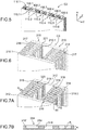
- the enclosure of the heat pipe comprises a stack of plates delimiting the steam channel 8 and the grooves 10.
- the stack comprises two end plates 12 located at the ends of the stack in a direction Z orthogonal to the X and Y directions.
- the end plates 12 are intended to close the channel 8 and are also designated "closure plates”. .
- the stack also includes spacer plates 14, 16, 17 disposed between the end plates 12.
- the spacer plates comprise a set of first spacer plates 14, a set of second spacer plates 16, and a set of third spacer plates 17 , the plates of the different games being superimposed so as to delimit the channel 8 and the grooves 10.
- the surface of the plates may vary. It can be envisaged that the surface of the plates decreases in the direction Z. It is also conceivable that the width of the spacer plates is variable along the direction X, for example to produce a condenser of larger area than the evaporator.
- the windows are shaped so as to cover the whole surface, they are not parallel.
- the stack comprises subgroups G1, G2 ... of spacer plates comprising in this order, a first plate 14, a second plate 16 and a first plate 14. Two subgroups are separated by a third plate 17. At the ends of the stack, the third plates 17 are replaced by the closure plates 12.
- a subgroup and two third plates delimit two grooves 10 with their exchange zone and the liquid channel.
- the first spacer plates comprise a central window 18 extending along the longitudinal axis X, and two side windows 19, located on either side of the central window 18 and extending along the longitudinal axis. X.
- the central window 18 is separated from each side window 19 by a post 21.
- the first spacer plates 14 have a thickness e1.
- the window 18 is designated "central window” because it is between the two side windows, but it will be understood that it is not necessarily located in the center of the first plate.
- the windows 18 and 19 have a rectangular shape having the same dimension in the X direction.
- the central window 18 has a dimension L1 in the Y direction and the side windows 19 have a dimension L1 'in the Y direction.
- Each second spacer plate 16 has a thickness e2 and has a window 20 extending in the X direction and in the Y direction.
- the window 20 has a rectangular shape having a dimension I2 in the X direction and an L2 dimension in the Y direction.
- the dimensions of the windows 18 and 20 in the direction X are preferably equal or close and correspond to the length of the channel 8.
- the dimension L2 is close to or equal to the distance between the two outer lateral edges of the windows 19, so that by placing a second intermediate plate 16 between two first intermediate plates 14, and by superposing the windows, the lateral edges External windows 19 are aligned with the lateral edges of the window 20. This alignment delimits a flat bottom for grooves 10.
- the third spacer plates 17 close the grooves in the Z direction.
- Two uprights 19 of two successive first interlayer plates 14 form the transverse edges of the exchange zone 10.1 of a groove, and the thickness e2 of the second spacer plate delimits the dimension of the exchange zone in the Z direction.
- the third plates advantageously participate in defining two grooves 10 superimposed in the direction Z.
- each group has its own two third plates.
- each group G1, G2 ... defines two grooves facing each other.
- a single groove could be defined, in this case the first plates 14 would include only one side window.
- the steam channel 8 has a dimension in the direction Y equal to L1 'and a dimension in the direction Z equal to the sum of the thicknesses of all the first, second and third intermediate plates.
- the exchange zone 10.1 of each groove has a dimension in the direction Z equal to e2.
- the liquid channel 10.2 has a dimension in the Z direction equal to 2e1 + e2 and a dimension in the Y direction equal to L1 '.
- the invention has the advantage of being able to separately set the width of the exchange zone 10.1 and the section of the liquid channel 10.2.
- the width is defined along the Z direction.
- second spacer plates of very small thickness e2 to have a small width of the exchange zone 10.2, and to use first spacer plates 14 of significant thickness e1 and dimensions L1 'important to make a liquid channel of important section.
- the width of the reentrant grooves It is not less than 0.5 mm and the size of the liquid channel in the extruded cylindrical heat pipes is typically 1.5 mm in diameter, it then offers a channel section of 1.76 mm 2 .
- the width / section ratio of the liquid channel is about 0.28.
- the width of the exchange zone can reach about 0.05 mm
- the liquid channel which is for example of rectangular section can have a dimension in the Z direction of 1.2 mm and a dimension in the Y direction of 2 mm, ie a section of 2.4 mm 2 .
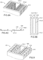
- Capillary pressure is the pressure difference between the vapor phase and the liquid phase in the vicinity of the meniscus.
- the meniscuses M represented at the exchange zone 10.1 of the grooves 10 can be seen at the level of the evaporator, and on the Figure 4B at the condenser level.
- the wetting angle is close to 90 °, and at the evaporator zone the wetting angle is at its minimum value.
- this minimum angle can be equal to 0.
- the capillary pressure is inversely proportional to the radius of curvature of the meniscus. This radius of curvature is very large at the condenser, and is substantially lower at the evaporator.
- the heat pipe has a plurality of liquid channels along the Z direction separated by the third spacer plates.
- the third spacer plates conduct heat from the plate 12 to the menisci of each liquid channel where evaporation occurs.
- the first plates have a thickness of between 0.05 mm and 6 mm, preferably equal to 0.5 mm.
- the second plates which fix the width of the exchange zones have a thickness of between 0.05 mm and 1 mm, preferably equal to 0.2 mm.
- the liquid channels have for example a dimension in the Y direction which can vary between 1 mm and 4 mm, and preferably be equal to 2 mm.
- the vapor channels have a width of between 2 mm and 8 mm, and preferably equal to 4 mm.
- the external dimensions of the heat pipes are between a few centimeters and a few meters.
- the maximum size of the heat pipes is generally limited by the available tools.
- the assembly of the sheets by vacuum brazing requires vacuum furnaces of large size, a few meters in length.
- large machines are also required.
- the mechanical strength of sheets with cuts of small width and great length is to be taken into account.
- the windows are made by punching, cutting, for example by laser or water jet.
- the heat pipe is filled with a two-phase fluid, it may be a fluid well known to those skilled in the art. This is chosen for example depending on the operating temperature range and storage of the device, depending on the constraints due to pressure, flammability, fluid toxicity and chemical compatibility between the fluid and the material. forming the heat pipe.
- a heat pipe made of aluminum alloy assembled by eutectic solder ammonia, acetone, methanol, n-heptane, R134a or other fluorinated refrigerants can be used as the fluid.
- the second spacer plates 16 by assembling metal strips, which would simplify the problem of mechanical strength of thin sheets and small cutting widths.
- the heat pipe C2 has vapor channels 108.1 to 108.6 arranged parallel to each other in the longitudinal direction X, each steam channel being connected to grooves 110.1 to 110.6 arranged laterally on either side of each steam channel 108.1 to 108.6 .
- the heat pipe C1 is a repeating pattern several times in the heat pipe C2. The pattern is delimited by the dashed lines.
- the heat pipe C2 is made by superimposing plates extending in one piece in the direction Y. Thus all the channels and all the grooves are made by stacking the same plates. The embodiment is then simplified because a large heat pipe is made in one piece, without the problem of the arrangement of the channels and grooves with respect to each other during assembly
- the spacer plates are structured so that the bottoms of two grooves opening into two adjacent channels are formed by the same elements of spacer plates.
- the time of realization of the plates is reduced and the density of channels and grooves is optimized.
- the heat pipes are isolated fluidly from each other.
- the heat pipes communicate fluidly with each other. The dimensions and the pitch between the heat pipes are chosen according to the application.
- This heat pipe C3 differs from the heat pipe C1, in that each groove 210 is delimited between two third plates 217 by a first plate 214 and a second plate 216.
- the first plate 214 has a structure similar to that of the plate 14.
- the exchange zone 210.1 is delimited in the direction Z, on one side by the upright 221 of the first spacer plate 214 and on the other side by the third spacer plate 217.
- the width of the exchange zone 210.1 is equal to the thickness of the second intermediate plate 216.
- the dimension of the liquid channel 210.2 in the direction Z is equal to the sum of the thicknesses of the first intermediate plate 214 and the second intermediate plate 216.
- the number of plates used to manufacture the C3 heat pipe is reduced.
- the heat pipe C4 comprises between two closure plates 312, a stack of groups of plates H1, H2 ... Each group comprising two first intermediate plates 314 and a second intermediate plate 316 disposed between the first two intermediate plates 314.
- the second spacer plate 316 is similar in shape to the second spacer plate 16.
- the first intermediate plates 314 ( Figure 7B ) comprise a central window 318 and two lateral recesses 319 made in one of the faces of the first plates 314.
- the first intermediate plates 314 have a thickness e1 and the recesses 319 have a depth p1 smaller than the thickness e1.
- the recesses 319 are bordered by a frame 319 '.
- the dimension in the Y direction of the window 320 of the second intermediate plate 316 is equal to the distance between the outer edge of a recess 319 and the outer edge of the other recess 319.
- each group the first intermediate plates 314 are disposed on either side of the second spacer plate 316 by arranging the recesses 319 opposite.
- the liquid channels 310.2 of the grooves 310 are delimited by the recesses 319.
- the width in the Z direction of the exchange zone 310.1 is equal to the thickness e2 of the second intermediate plate and the width of the liquid channel 310.2 in the Z direction is equal to 2e1 + e2.
- This example of heat pipe offers a better mechanical strength of the grooves, indeed the first plates have a greater robustness.
- this embodiment has the advantage of not requiring the implementation of third interlayers, and sealing is simpler to achieve because of the reduced number of interplate interfaces.
- the windows 318 of the first intermediate plates 314 are for example made by punching and the recesses 319 are made by machining.
- the first spacer plates comprise a central window 418 and two lateral recesses 419 on either side of the central window.
- the heat pipe C5 does not have a second spacer plate between the two first spacer plates 414. These are the first spacer plates which delimit both the exchange zone 410.1 and the liquid channel 410.2.
- a top view of a first intermediate plate 414 can be seen, and on the Figure 8C one can see a sectional view along the Y direction of the first intermediate plate 414. It comprises the central window 418 and the recesses 419.
- the recesses 419 have three contiguous outer edges 419.1 located on the contiguous outer edges of the plate 414, and an inner edge 419.2 on the side of the window 418.
- the outer edges 419.1 have a thickness in the Z direction equal to the thickness e1 of the plate 419, and the inner edge 419.2 has a thickness h1 less than the thickness e1.
- the inner edges 419.2 of the two opposite recesses are not in contact and provide a space forming the exchange zone 410.1. .
- the exchange zone then has a width in the Z direction equal to 2 ⁇ (e1-h1).
- This embodiment has the advantage of providing improved mechanical strength of the grooves, to further reduce the number of different parts required to achieve the heat pipe and further simplify the realization of seals.
- first spacer plates 514 have recesses in their two faces and thus participate in delimiting each two grooves 510 in the Z direction.
- a second intermediate plate 516 is placed between two first intermediate plates and defines the width in the Z direction. of the trading area 510.1.
- the edges of the recesses all have the same thickness.
- the inner edge of the recesses is thinned.
- FIG 10 another example of a heat pipe C7 comprising two closure plates 612 and first spacer plates 614 having recesses on their two faces, the recesses having an inner edge 619.2 thinned with respect to the outer edges 619.1.
- the exchange zone is delimited by the thinned inner edges 619.2.
- the number of plates is reduced, which simplifies assembly and further reduces the number of interfaces, and therefore the risk of leakage.
- the stack comprises first plates provided with recesses and a third plate which delimits with the first plate the exchange zones.
- the first intermediate plates of the exemplary embodiments of the figures 9 and 10 can be made by extrusion.
- the plates do not come from clad sheets, and they are advantageously welded to each other by laser layer by layer transparency.
- the cut of the recesses along the Y axis has a rectangular shape.
- the inner face 719.21 of the inner edge 719.2 of the recess 719 is inclined towards the open face of the recess.
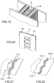
- the side windows 919 of the first spacer plate 914 have a trapezoidal shape in the XY plane, the large base 919.1 being located on the side of the condenser zone and the smaller base 919.2 being located on the evaporator side.
- the section of the liquid channel is smaller at the evaporator, where the liquid flow is less, and the exchange zone is wider in order to accept a larger meniscus retreat.
- the exchange zone 910.1 has a larger dimension in the Y direction at the evaporator zone than at the condenser zone. This longer exchange zone allows the meniscus of the larger liquid to retreat into the evaporator zone, which reduces the risk of the meniscus entering the liquid channel, and thus reduces the risk of a sudden decrease in capillary pressure. Such a decrease can cause the defusing of the heat pipe.
- the arrows symbolize the flow of fluid between the condenser zone and the evaporator zone, in the steam channel and in the reentrant grooves.
- the elongation of the exchange zone at the evaporator zone has the effect of reducing the section of the liquid channel 910.2 at the evaporator zone.
- the loss of liquid charge is slightly increased, and the capillary limit is slightly reduced.
- the side windows 1019 have a trapezoidal shape, the large base being located on the side of the condenser zone and the smaller base being located on the evaporator side; and the central window 1018 also has a trapezoidal shape, the largest base being on the evaporator zone side and the smaller base being on the condenser zone side.
- This variant makes it possible to optimize the losses of liquid and vapor pressure.
- FIG 16 another example of heat pipe C9 according to the invention can be seen integrating a thermal diffuser in order to homogenize the flow.
- the closure plates 12 have a greater surface area than those of the stack in the YX plane so that they protrude on either side of the stack. The heat flow then spreads over a wider area, which ensures homogenization of the flow.
- the heat pipe may have larger surface closure plates only in the area or areas of use, i.e. in the condenser zone and / or in the evaporator zone.
- the surface of the plates is advantageously reduced in the non-useful zone, for example cut before or after assembly, which makes it possible to reduce the mass of the heat pipe.
- closure plates also applies to multichannel heat pipes.
- the heat pipe C10 comprises two steam channels each surrounded by two reentrant channels, instead of a steam channel if we consider the Y direction that the heat pipe C1.
- This arrangement makes it possible to obtain improved pressure resistance with respect to the heat pipe C1.
- the failure of a heat pipe will keep 50% of the transport capacity of the assembly.
- the thickness of the wall between two vapor channels may be thinner than the outer walls which have to maintain a higher pressure difference.
- the heat pipe C10 has a lower limit power than the C1 heat pipe, but the thermal resistance, which is related to the surface of the exchange zones, is lower.
- the heat pipe C11 comprises a partition 24 in the steam channel mechanically connected to the two closure plates and providing reinforcement of the heat pipe in the Z direction.
- the partition 24 is formed by stacking the plates.
- the partition 24 may be such that it provides fluid communication between the two parts of the steam channel, which simplifies the filling.
- the partition 24 separates the steam channel and two half-channel vapors, which allows in case of failure of one of the half heat pipes that retain 50% of transport capacity.
- the stack comprises reinforcing strands 26 extending in the Y direction and which pass through the channel.
- the strands are formed by the third spacer plate 17 which is visible on the figure 20 .
- the strands 26 connect the two uprights 28 of the third spacer plate and define a plurality of windows.
- Reinforcement of the internal structure of the heat pipe can also be obtained by increasing the thickness of the walls formed by the stack of the plates.
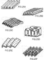
- edges of the openings defining the grooves are straight and parallel to each other.
- first intermediate plates 1114 having windows 1118 including corrugated side edges 1118.1.
- This shape makes it possible to increase the length of the triple line (connection zone between liquid / vapor and wall), in particular in the evaporator zone, which makes it possible to increase the evaporation exchange coefficient.
- the corrugated shape makes it possible to obtain walls not wetted by the condensation film at the vertices of the corrugations. This also makes it possible to increase the condensation exchange coefficient by minimizing the interface resistance of the condensation film. In addition at the condenser, the meniscus is flush with the vapor zone, which increases the condensation area.
- the corrugations can be provided at the condenser zone and / or at the evaporator zone.
- the corrugations are formed along the entire length of the heat pipe, which simplifies the implementation and makes it possible to adapt to different lengths of condensation zone or evaporation zone.
- the bottom of the grooves is plant.
- the filling of a single-channel heat pipe can be done by means of a filling tube inserted on the edge of the stack or by means of a tube fastened to an orifice formed in one of the closure plates, for example perpendicularly to these.
- a channel puts all channels in communication.
- This channel is for example formed by a transverse lumen 30 formed on an edge of one of the third spacer plates 1317.
- the side windows 1319 of the first plate 1317 are extended along the X axis so that, when stacking in the Z direction, the longitudinal ends of the side windows 1319 are at the right of the light 30.
- the heat pipe C12 has two straight portions D1 and D2 oriented at right angles to one another.
- the portions D1 and D2 extend in orthogonal planes.
- the portion D1 extends in the plane XY and the portion D2 extends in the plane XZ.
- the orientation of the portions D1 and D2 relative to each other is for example obtained by folding after stacking the plates and their joining. P1 denotes the fold.
- the C12 heat pipe can be consistent with the application.
- the heat pipe may have several bends.
- the portion D1 forms the evaporator and the portion D2 forms the condenser and is provided on its outer surfaces with fins A1 forming a radiator for evacuating heat.
- the radiator works for example in natural convection or forced convection.
- the fins A1 are provided on both large surface surfaces of the condenser. Alternatively, fins could be considered on one side.
- the fins comprise flat plates perpendicular to the faces of the condenser. Any other form is conceivable.
- the fins are extruded fins, skived fins, pinned fins, molded fins, knuckle-fixed fins, fins produced by 3D printing, or any other fin obtained by a technique of performing extension of surface well known to those skilled in the art.
- One or more finned radiators as described above can be implemented in a single-channel heat pipe or multichannel straight or in any other form.
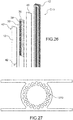
- a cooling circuit is integrated directly into the heat pipe C13 as shown in FIG. figure 26 .
- the heat pipe comprises a cooling circuit 32 in which is intended to circulate a heat transfer fluid.
- the cooling circuit is in direct contact with the condenser.
- the cooling circuit 32 is formed by an additional plate 36, in which are formed grooves 38 defining the side walls of the circuit, and the closure plate 12 and an additional closure plate 40 form the walls of the end of the cooling circuit.
- the closure plate 12 has two orifices 42 each opening at one end of the circuit and allowing the circulation of the coolant.
- the coolant can be a liquid or a gas.
- it is a two-phase circuit.
- Such a circuit can also be used to form the hot source at the evaporator.
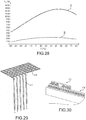
- a heat pipe of the prior art cylindrical obtained by extrusion and having reentrant grooves 1310, as shown in FIG. figure 27 .
- Each heat pipe has a length of the evaporator of 200 mm, a length of the adiabatic zone of 600 mm, a length of the condenser of 200 mm (total length 1m).
- Each heat pipe is made of aluminum alloy.
- the working temperature in the adiabatic zone of the heat pipe is 60 ° C; i.e. the average vapor temperature of the heat pipe.
- the working fluid is ammonia.
- the heat pipe according to the invention has the following characteristics:
- the heat pipe has a section of 13.2 mm ⁇ 13.2 mm and wings formed by closing plates of 30 mm in the Y direction.
- the section of the heat pipe is represented in Figure 16 .
- the heat pipe of the state of the art has outer bulk close to that of the heat pipe according to the invention above and has a mass of 300 g.
- the heat pipe according to the invention has, at identical dimensions, a power limit of 4 to 6 times greater than that of a heat pipe of the state of the art, for a slightly greater mass.
- the heat pipe according to the invention requires only two levels of grooves, i.e. four grooves.
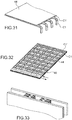
- This heat pipe will for example be the same width less thick, it is represented in figure 33 .
- the heat pipe of the figure 33 has a section of 13.2 mm ⁇ 4.9 mm and wings formed by closure plates of 30 mm in the Y direction, and a mass of 210 g.
- the cylindrical heat pipe of the state of the art has a section of 13.2 mm ⁇ 13.2 mm and wings formed by the closing plates of 30 mm, and a mass of 300 g.
- a gain on the empty weight of 30% and a gain of 68% over the thickness of the heat pipe can be obtained thanks to the invention with respect to cylindrical heat pipes reentrant grooves of the state of the art.
- the thermal resistances of the flow between the hot and / or cold sources are more advantageous in the heat pipes as in the cylindrical heat pipes reentrant grooves.
- the cylindrical heat pipes with reentrant grooves of the state of the art has a reduction of flow transmission section by conduction more marked (constriction of heat flow by conduction) which is unfavorable to thermal resistances.
- the thermal path is more complex and longer with the heat pipes of the state of the art.
- heat pipes according to the invention such as that of the figure 1 , arranged in the form of a lattice, the heat pipes C1 and C1 'intersecting at right angles in the example shown.
- the heat pipes C1 are folded so as to be deployed in two perpendicular planes.
- the heat pipes C1 extend along the axis a1 and the heat pipes extend along the axis a2.
- the heat pipes can be connected fluidically or not.
- the heat pipes in the same plane can communicate together thanks to the lights provided in the intermediate plates, as represented on the figure 23 .
- the example in which the heat pipes are not fluidly connected to each other has the advantage of offering redundancy in the event that one of the heat pipes is defective.
- FIG. 30 a cross-sectional view at a node of a heat pipe C1 and a heat pipe C1 'can be seen in the case of heat pipe not connected fluidically.
- a closure plate of a heat pipe C1 also forms the closure plate of a heat pipe C1 '.
- the pressurizing tooling during brazing is preferably planar and will rest on the outside of the two closure plates.
- the sheets cover the entire surface before soldering. We can nevertheless open the plates before assembly to lighten the whole.
- the non-useful areas can be removed by machining, trimming or cutting to obtain the desired geometry and to lighten the structure as much as possible.
- the sheets of the heat pipes C1 'above the heat pipes C1 are removed by machining.
- the inter-heat pipe spaces are perforated.
- this mesh is hollowed out.
- a metal veil is a very thin metal sheet, typically of the order of 0.2 mm, which is for example glued on the heat pipes.
- a cross-linked heat pipe system can be made in one piece, ie the interfaces between the intersecting heat pipes are formed by a common plate for the intersecting heat pipes, and not by two plates in contact with one another. with the other.
- the thermal interface resistances at the node of the trellis are substantially reduced.
- the mesh may be self-supporting, which may make it possible not to implement an additional support structure.
- the heat pipes can form a lattice in which the heat pipes intersect at an angle not right.
- the angle may vary over the entire surface of the lattice.
- the spacing between the heat pipes can be variable.
- the mesh may comprise heat pipes of different sizes.
- the heat pipe according to the invention can be made of different materials such as, for example, an aluminum alloy, copper, stainless steel.
- the technique of joining the sheets depends on the material.
- the solder diffusion In the case of copper plate, stainless steel or superalloy, it is possible to use the solder diffusion, the laser welding, the solder diffusion, the bonding ... the material or materials used for the manufacture of the heat pipe are chosen according to the mass constraints, assembly, robustness required ...
- the assembly of aluminum alloy plates is obtained by eutectic soldering.
- Aluminum alloy plates are used in known manner, one or both of which faces or is coated with an aluminum alloy having a lower melting point.
- an alloy sheet of the AA3xxxx series core is used, with a coating with a eutectic alloy of the AA4xxxx series comprising silicon having a lower melting point.
- the coating is typically done by a roll-bond technique.
- the total thickness of the plates is typically from 0.05 mm to 5 mm, with a coating typically from 5% to 10% of the total thickness on one or both sides.
- the eutectic alloy melts on the surface and forms a solder alloy. sealing assembly between the two plates.
- Brazing is preferably carried out under pressure by means of a mechanical holding system, which maintains the stack under pressure during soldering in a vacuum oven.
- Cutouts and / or bends are required in the manufacturing process to lighten and / or shape the structure. They are preferably made after assembly. It should be noted that the cutting of windows in the plates, for example the central windows, is performed before assembly.
- Plates of a given material are cut in the desired outer shape for the heat pipe.
- the first, second and third spacer plates are structured, for example by punching, machining, cutting laser, by cutting with water jet or by chemical etching through ... in order to achieve the specific windows in the different plates, so that once assembled a heat pipe with reentrant grooves is formed.
- the plates are then stacked in a given order, for example by alternating a second intermediate plate and a third intermediate plate between two first intermediate plates; closure plates are disposed at the ends of the stack to close the channel (s).
- Optionally cooling channels are provided on one or both sides of the stack.
- the plates are assembled, the assembly technique being chosen according to the material or materials of the plates, for example welding, brazing, gluing ... the assembly of the plates is sealed.
- the material or materials of the plates is or are chosen in function of the working fluid, which is itself chosen according to the thermalization specifications of the system to be produced.
- the heat pipe is then filled.
- a fill port was provided in one of the opening plates during the manufacture of the plates.
- the fluid is chosen according to the operating conditions of the heat pipe (operating temperature, etc.) and the compatibility with the material or materials of the heat pipe.
- the thermal performance in terms of maximum transportable power of the reentrant-grooved heat pipes is improved over the reentrant re-entrant heat pipe heat pipes, i.e. the reentrant-groove cylindrical heat pipes.
- the thermal performance in terms of maximum transportable power of the reentrant-grooved heat pipes is improved over the reentrant re-entrant heat pipe heat pipes, i.e. the reentrant-groove cylindrical heat pipes.
- the second intermediate plates can be removed, which reduces the number of parts used.
- the plates have increased robustness.
Landscapes
- Engineering & Computer Science (AREA)
- Life Sciences & Earth Sciences (AREA)
- Sustainable Development (AREA)
- Physics & Mathematics (AREA)
- Thermal Sciences (AREA)
- Mechanical Engineering (AREA)
- General Engineering & Computer Science (AREA)
- Heat-Exchange Devices With Radiators And Conduit Assemblies (AREA)
Applications Claiming Priority (1)
| Application Number | Priority Date | Filing Date | Title |
|---|---|---|---|
| FR1853170A FR3080172B1 (fr) | 2018-04-11 | 2018-04-11 | Caloduc a pompage capillaire a rainures reentrantes offrant un fonctionnement ameliore |
Publications (3)
| Publication Number | Publication Date |
|---|---|
| EP3553445A1 true EP3553445A1 (de) | 2019-10-16 |
| EP3553445B1 EP3553445B1 (de) | 2021-02-17 |
| EP3553445B8 EP3553445B8 (de) | 2021-04-07 |
Family
ID=62684911
Family Applications (1)
| Application Number | Title | Priority Date | Filing Date |
|---|---|---|---|
| EP19168586.6A Active EP3553445B8 (de) | 2018-04-11 | 2019-04-11 | Verbessertes wärmerohr mit kapillarstrukturen mit wiedereintrittsrillen |
Country Status (2)
| Country | Link |
|---|---|
| EP (1) | EP3553445B8 (de) |
| FR (1) | FR3080172B1 (de) |
Cited By (8)
| Publication number | Priority date | Publication date | Assignee | Title |
|---|---|---|---|---|
| EP4166881A1 (de) | 2021-10-18 | 2023-04-19 | Commissariat à l'énergie atomique et aux énergies alternatives | Modul zur herstellung eines wärmerohrs mit kapillarpumpe mit wiedereintrittsnuten |
| FR3128279A1 (fr) | 2021-10-18 | 2023-04-21 | Commissariat A L'energie Atomique Et Aux Energies Alternatives | Caloduc de type à pompage capillaire avec rainures réentrantes à limites d’ébullition et capillaire augmentées. |
| FR3128281A1 (fr) | 2021-10-18 | 2023-04-21 | Commissariat A L'energie Atomique Et Aux Energies Alternatives | Caloduc de type à pompage capillaire avec rainures réentrantes à gestion de liquide améliorée. |
| FR3128280A1 (fr) | 2021-10-18 | 2023-04-21 | Commissariat A L'energie Atomique Et Aux Energies Alternatives | Caloduc de type à pompage capillaire avec rainures réentrantes à conductivité thermique augmentée. |
| WO2024027962A1 (fr) * | 2022-08-03 | 2024-02-08 | Calyos Sa | Echangeur de chaleur |
| EP4325155A1 (de) | 2022-08-17 | 2024-02-21 | Commissariat à l'énergie atomique et aux énergies alternatives | Wärmerohr mit nichtzylindrischem querschnitt mit einem verdampfer mit verbesserter dampf-flüssigkeits-grenzflächenstruktur zur erhöhung der kochgrenze |
| EP4325156A1 (de) | 2022-08-17 | 2024-02-21 | Commissariat à l'énergie atomique et aux énergies alternatives | Kapillarpumpwärmerohr mit ablenkrillen, die mindestens ein poröses substrat im verdampfer integriert |
| EP4325158A1 (de) | 2022-08-17 | 2024-02-21 | Commissariat à l'énergie atomique et aux énergies alternatives | Kapillarpumpwärmerohr mit quer zur längsachse des wärmerohrs verlaufenden rillen |
Citations (4)
| Publication number | Priority date | Publication date | Assignee | Title |
|---|---|---|---|---|
| FR2776763A1 (fr) * | 1998-03-30 | 1999-10-01 | Atmostat Etudes Et Rech | Dispositif d'echanges thermiques a fluide biphasique actif et procede de fabrication d'un tel dispositif |
| FR2776764A1 (fr) * | 1998-03-30 | 1999-10-01 | Atmostat Etudes Et Rech | Dispositif d'echanges thermiques a fluide biphasique actif et procede de fabrication d'un tel dispositif |
| WO2009072703A1 (en) * | 2007-12-04 | 2009-06-11 | Electronics And Telecommunications Research Institute | Flat plate type micro heat transport device |
| US20120145358A1 (en) * | 2010-12-13 | 2012-06-14 | Electronics And Telecommunications Research Institute | Thinned flat plate heat pipe fabricated by extrusion |
-
2018
- 2018-04-11 FR FR1853170A patent/FR3080172B1/fr active Active
-
2019
- 2019-04-11 EP EP19168586.6A patent/EP3553445B8/de active Active
Patent Citations (4)
| Publication number | Priority date | Publication date | Assignee | Title |
|---|---|---|---|---|
| FR2776763A1 (fr) * | 1998-03-30 | 1999-10-01 | Atmostat Etudes Et Rech | Dispositif d'echanges thermiques a fluide biphasique actif et procede de fabrication d'un tel dispositif |
| FR2776764A1 (fr) * | 1998-03-30 | 1999-10-01 | Atmostat Etudes Et Rech | Dispositif d'echanges thermiques a fluide biphasique actif et procede de fabrication d'un tel dispositif |
| WO2009072703A1 (en) * | 2007-12-04 | 2009-06-11 | Electronics And Telecommunications Research Institute | Flat plate type micro heat transport device |
| US20120145358A1 (en) * | 2010-12-13 | 2012-06-14 | Electronics And Telecommunications Research Institute | Thinned flat plate heat pipe fabricated by extrusion |
Cited By (16)
| Publication number | Priority date | Publication date | Assignee | Title |
|---|---|---|---|---|
| EP4166881A1 (de) | 2021-10-18 | 2023-04-19 | Commissariat à l'énergie atomique et aux énergies alternatives | Modul zur herstellung eines wärmerohrs mit kapillarpumpe mit wiedereintrittsnuten |
| FR3128279A1 (fr) | 2021-10-18 | 2023-04-21 | Commissariat A L'energie Atomique Et Aux Energies Alternatives | Caloduc de type à pompage capillaire avec rainures réentrantes à limites d’ébullition et capillaire augmentées. |
| FR3128281A1 (fr) | 2021-10-18 | 2023-04-21 | Commissariat A L'energie Atomique Et Aux Energies Alternatives | Caloduc de type à pompage capillaire avec rainures réentrantes à gestion de liquide améliorée. |
| FR3128278A1 (fr) | 2021-10-18 | 2023-04-21 | Commissariat A L'energie Atomique Et Aux Energies Alternatives | Module pour la fabrication d’un caloduc a pompe capillaire a rainures réentrantes |
| FR3128280A1 (fr) | 2021-10-18 | 2023-04-21 | Commissariat A L'energie Atomique Et Aux Energies Alternatives | Caloduc de type à pompage capillaire avec rainures réentrantes à conductivité thermique augmentée. |
| WO2023066754A1 (fr) | 2021-10-18 | 2023-04-27 | Commissariat A L'energie Atomique Et Aux Energies Alternatives | Caloduc de type à pompage capillaire avec rainures réentrantes à limites d'ébullition et capillaire augmentées. |
| WO2023066755A1 (fr) | 2021-10-18 | 2023-04-27 | Commissariat A L'energie Atomique Et Aux Energies Alternatives | Caloduc de type à pompage capillaire avec rainures réentrantes à conductivité thermique augmentée |
| WO2023066753A1 (fr) | 2021-10-18 | 2023-04-27 | Commissariat A L'energie Atomique Et Aux Energies Alternatives | Caloduc de type a pompage capillaire avec rainures reentrantes a gestion de liquide amelioree |
| WO2024027962A1 (fr) * | 2022-08-03 | 2024-02-08 | Calyos Sa | Echangeur de chaleur |
| FR3138687A1 (fr) * | 2022-08-03 | 2024-02-09 | Calyos Sa | Echangeur de chaleur |
| EP4325155A1 (de) | 2022-08-17 | 2024-02-21 | Commissariat à l'énergie atomique et aux énergies alternatives | Wärmerohr mit nichtzylindrischem querschnitt mit einem verdampfer mit verbesserter dampf-flüssigkeits-grenzflächenstruktur zur erhöhung der kochgrenze |
| EP4325156A1 (de) | 2022-08-17 | 2024-02-21 | Commissariat à l'énergie atomique et aux énergies alternatives | Kapillarpumpwärmerohr mit ablenkrillen, die mindestens ein poröses substrat im verdampfer integriert |
| EP4325158A1 (de) | 2022-08-17 | 2024-02-21 | Commissariat à l'énergie atomique et aux énergies alternatives | Kapillarpumpwärmerohr mit quer zur längsachse des wärmerohrs verlaufenden rillen |
| FR3138942A1 (fr) | 2022-08-17 | 2024-02-23 | Commissariat A L'energie Atomique Et Aux Energies Alternatives | Caloduc de type à pompage capillaire, à rainures réentrantes intégrant au moins un substrat poreux à l’évaporateur. |
| FR3138941A1 (fr) | 2022-08-17 | 2024-02-23 | Commissariat A L'energie Atomique Et Aux Energies Alternatives | Caloduc de type à pompage capillaire, à rainures réentrantes transversales à l’axe longitudinal du caloduc. |
| FR3138943A1 (fr) | 2022-08-17 | 2024-02-23 | Commissariat A L'energie Atomique Et Aux Energies Alternatives | Caloduc à section transversale non cylindrique, comprenant un évaporateur à structure d’interface vapeur/liquide améliorée afin d’augmenter la limite d’ébullition. |
Also Published As
| Publication number | Publication date |
|---|---|
| EP3553445B8 (de) | 2021-04-07 |
| FR3080172A1 (fr) | 2019-10-18 |
| EP3553445B1 (de) | 2021-02-17 |
| FR3080172B1 (fr) | 2020-05-08 |
Similar Documents
| Publication | Publication Date | Title |
|---|---|---|
| EP3553445B1 (de) | Verbessertes wärmerohr mit kapillarstrukturen mit wiedereintrittsrillen | |
| EP2689205B1 (de) | Anschlussbewehrung zwischen platten eines wärmetauschers | |
| EP3561428B1 (de) | Wärmeleitrohr mit kapillarpumpensystem mit verbesserter funktionsweise | |
| EP2912396B1 (de) | Wärmetauscher, insbesondere für ein kraftfahrzeug | |
| EP4325156B1 (de) | Kapillarpumpwärmerohr mit ablenkrillen, die mindestens ein poröses substrat im verdampfer integriert | |
| WO2016097032A1 (fr) | Plaque d'echange thermique a microcanaux et echangeur thermique comportant au moins une telle plaque | |
| EP4419856B1 (de) | Kapillargepumptes wärmerohr mit wiedereintrittsrillen mit erhöhten siede- und kapillargrenzen | |
| EP1068481B1 (de) | Zweiphasige wärmeaustauschvorrichtung | |
| EP3553444B1 (de) | Verbessertes wärmerohr | |
| EP4419855B1 (de) | Kapillargepumptes wärmerohr mit wiedereintrittsrillen mit verbesserter flüssigkeitsverwaltung | |
| EP4325158B1 (de) | Kapillarpumpwärmerohr mit quer zur längsachse des wärmerohrs verlaufenden rillen | |
| EP4325155A1 (de) | Wärmerohr mit nichtzylindrischem querschnitt mit einem verdampfer mit verbesserter dampf-flüssigkeits-grenzflächenstruktur zur erhöhung der kochgrenze | |
| EP4018146B1 (de) | Wärmetauscher, insbesondere für ein kraftfahrzeug, und verfahren zur herstellung eines solchen wärmetauschers | |
| WO2017109355A1 (fr) | Échangeur thermique, notamment pour vehicule automobile | |
| WO2017109344A1 (fr) | Échangeur thermique, notamment pour véhicule automobile | |
| EP4419854B1 (de) | Kapillar gepumptes wärmerohr mit rückeinspeisungskanälen zur verbesserten wärmeleitfähigkeit | |
| EP4521052B1 (de) | Plattenwärmetauscher zur phasentrennung | |
| EP3394546B1 (de) | Wärmetauscher, insbesondere für ein kraftfahrzeug | |
| WO2017109354A1 (fr) | Échangeur thermique, notamment pour véhicule automobile | |
| WO2017109350A1 (fr) | Échangeur thermique, notamment pour vehicule automobile | |
| WO2017109345A1 (fr) | Échangeur thermique, notamment pour véhicule automobile | |
| WO2017109347A1 (fr) | Échangeur thermique, notamment pour véhicule automobile |
Legal Events
| Date | Code | Title | Description |
|---|---|---|---|
| PUAI | Public reference made under article 153(3) epc to a published international application that has entered the european phase |
Free format text: ORIGINAL CODE: 0009012 |
|
| STAA | Information on the status of an ep patent application or granted ep patent |
Free format text: STATUS: REQUEST FOR EXAMINATION WAS MADE |
|
| 17P | Request for examination filed |
Effective date: 20190411 |
|
| AK | Designated contracting states |
Kind code of ref document: A1 Designated state(s): AL AT BE BG CH CY CZ DE DK EE ES FI FR GB GR HR HU IE IS IT LI LT LU LV MC MK MT NL NO PL PT RO RS SE SI SK SM TR |
|
| AX | Request for extension of the european patent |
Extension state: BA ME |
|
| RIC1 | Information provided on ipc code assigned before grant |
Ipc: F28D 15/02 20060101AFI20200507BHEP Ipc: F28D 15/04 20060101ALI20200507BHEP |
|
| GRAP | Despatch of communication of intention to grant a patent |
Free format text: ORIGINAL CODE: EPIDOSNIGR1 |
|
| STAA | Information on the status of an ep patent application or granted ep patent |
Free format text: STATUS: GRANT OF PATENT IS INTENDED |
|
| INTG | Intention to grant announced |
Effective date: 20200903 |
|
| GRAS | Grant fee paid |
Free format text: ORIGINAL CODE: EPIDOSNIGR3 |
|
| GRAA | (expected) grant |
Free format text: ORIGINAL CODE: 0009210 |
|
| STAA | Information on the status of an ep patent application or granted ep patent |
Free format text: STATUS: THE PATENT HAS BEEN GRANTED |
|
| AK | Designated contracting states |
Kind code of ref document: B1 Designated state(s): AL AT BE BG CH CY CZ DE DK EE ES FI FR GB GR HR HU IE IS IT LI LT LU LV MC MK MT NL NO PL PT RO RS SE SI SK SM TR |
|
| REG | Reference to a national code |
Ref country code: GB Ref legal event code: FG4D Free format text: NOT ENGLISH |
|
| REG | Reference to a national code |
Ref country code: CH Ref legal event code: EP |
|
| REG | Reference to a national code |
Ref country code: DE Ref legal event code: R096 Ref document number: 602019002492 Country of ref document: DE |
|
| REG | Reference to a national code |
Ref country code: CH Ref legal event code: PK Free format text: RECTIFICATION B8 Ref country code: AT Ref legal event code: REF Ref document number: 1362009 Country of ref document: AT Kind code of ref document: T Effective date: 20210315 |
|
| REG | Reference to a national code |
Ref country code: IE Ref legal event code: FG4D Free format text: LANGUAGE OF EP DOCUMENT: FRENCH |
|
| RAP2 | Party data changed (patent owner data changed or rights of a patent transferred) |
Owner name: AIRBUS DEFENCE AND SPACE SAS Owner name: COMMISSARIAT A L'ENERGIE ATOMIQUE ET AUX ENERGIES ALTERNATIVES |
|
| REG | Reference to a national code |
Ref country code: DE Ref legal event code: R081 Ref document number: 602019002492 Country of ref document: DE Owner name: COMMISSARIAT A L'ENERGIE ATOMIQUE ET AUX ENERG, FR Free format text: FORMER OWNER: COMMISSARIAT A L'ENERGIE ATOMIQUE ET AUX ENERGIES ALTERNATIVES, PARIS, FR Ref country code: DE Ref legal event code: R081 Ref document number: 602019002492 Country of ref document: DE Owner name: AIRBUS DEFENCE AND SPACE SAS, FR Free format text: FORMER OWNER: COMMISSARIAT A L'ENERGIE ATOMIQUE ET AUX ENERGIES ALTERNATIVES, PARIS, FR |
|
| REG | Reference to a national code |
Ref country code: LT Ref legal event code: MG9D |
|
| REG | Reference to a national code |
Ref country code: NL Ref legal event code: MP Effective date: 20210217 |
|
| PG25 | Lapsed in a contracting state [announced via postgrant information from national office to epo] |
Ref country code: NO Free format text: LAPSE BECAUSE OF FAILURE TO SUBMIT A TRANSLATION OF THE DESCRIPTION OR TO PAY THE FEE WITHIN THE PRESCRIBED TIME-LIMIT Effective date: 20210517 Ref country code: PT Free format text: LAPSE BECAUSE OF FAILURE TO SUBMIT A TRANSLATION OF THE DESCRIPTION OR TO PAY THE FEE WITHIN THE PRESCRIBED TIME-LIMIT Effective date: 20210617 Ref country code: LT Free format text: LAPSE BECAUSE OF FAILURE TO SUBMIT A TRANSLATION OF THE DESCRIPTION OR TO PAY THE FEE WITHIN THE PRESCRIBED TIME-LIMIT Effective date: 20210217 Ref country code: BG Free format text: LAPSE BECAUSE OF FAILURE TO SUBMIT A TRANSLATION OF THE DESCRIPTION OR TO PAY THE FEE WITHIN THE PRESCRIBED TIME-LIMIT Effective date: 20210517 Ref country code: FI Free format text: LAPSE BECAUSE OF FAILURE TO SUBMIT A TRANSLATION OF THE DESCRIPTION OR TO PAY THE FEE WITHIN THE PRESCRIBED TIME-LIMIT Effective date: 20210217 Ref country code: HR Free format text: LAPSE BECAUSE OF FAILURE TO SUBMIT A TRANSLATION OF THE DESCRIPTION OR TO PAY THE FEE WITHIN THE PRESCRIBED TIME-LIMIT Effective date: 20210217 Ref country code: GR Free format text: LAPSE BECAUSE OF FAILURE TO SUBMIT A TRANSLATION OF THE DESCRIPTION OR TO PAY THE FEE WITHIN THE PRESCRIBED TIME-LIMIT Effective date: 20210518 |
|
| REG | Reference to a national code |
Ref country code: AT Ref legal event code: MK05 Ref document number: 1362009 Country of ref document: AT Kind code of ref document: T Effective date: 20210217 |
|
| PG25 | Lapsed in a contracting state [announced via postgrant information from national office to epo] |
Ref country code: RS Free format text: LAPSE BECAUSE OF FAILURE TO SUBMIT A TRANSLATION OF THE DESCRIPTION OR TO PAY THE FEE WITHIN THE PRESCRIBED TIME-LIMIT Effective date: 20210217 Ref country code: LV Free format text: LAPSE BECAUSE OF FAILURE TO SUBMIT A TRANSLATION OF THE DESCRIPTION OR TO PAY THE FEE WITHIN THE PRESCRIBED TIME-LIMIT Effective date: 20210217 Ref country code: PL Free format text: LAPSE BECAUSE OF FAILURE TO SUBMIT A TRANSLATION OF THE DESCRIPTION OR TO PAY THE FEE WITHIN THE PRESCRIBED TIME-LIMIT Effective date: 20210217 Ref country code: NL Free format text: LAPSE BECAUSE OF FAILURE TO SUBMIT A TRANSLATION OF THE DESCRIPTION OR TO PAY THE FEE WITHIN THE PRESCRIBED TIME-LIMIT Effective date: 20210217 Ref country code: SE Free format text: LAPSE BECAUSE OF FAILURE TO SUBMIT A TRANSLATION OF THE DESCRIPTION OR TO PAY THE FEE WITHIN THE PRESCRIBED TIME-LIMIT Effective date: 20210217 |
|
| PG25 | Lapsed in a contracting state [announced via postgrant information from national office to epo] |
Ref country code: IS Free format text: LAPSE BECAUSE OF FAILURE TO SUBMIT A TRANSLATION OF THE DESCRIPTION OR TO PAY THE FEE WITHIN THE PRESCRIBED TIME-LIMIT Effective date: 20210617 |
|
| PG25 | Lapsed in a contracting state [announced via postgrant information from national office to epo] |
Ref country code: CZ Free format text: LAPSE BECAUSE OF FAILURE TO SUBMIT A TRANSLATION OF THE DESCRIPTION OR TO PAY THE FEE WITHIN THE PRESCRIBED TIME-LIMIT Effective date: 20210217 Ref country code: EE Free format text: LAPSE BECAUSE OF FAILURE TO SUBMIT A TRANSLATION OF THE DESCRIPTION OR TO PAY THE FEE WITHIN THE PRESCRIBED TIME-LIMIT Effective date: 20210217 Ref country code: SM Free format text: LAPSE BECAUSE OF FAILURE TO SUBMIT A TRANSLATION OF THE DESCRIPTION OR TO PAY THE FEE WITHIN THE PRESCRIBED TIME-LIMIT Effective date: 20210217 Ref country code: AT Free format text: LAPSE BECAUSE OF FAILURE TO SUBMIT A TRANSLATION OF THE DESCRIPTION OR TO PAY THE FEE WITHIN THE PRESCRIBED TIME-LIMIT Effective date: 20210217 |
|
| REG | Reference to a national code |
Ref country code: DE Ref legal event code: R097 Ref document number: 602019002492 Country of ref document: DE |
|
| PG25 | Lapsed in a contracting state [announced via postgrant information from national office to epo] |
Ref country code: MC Free format text: LAPSE BECAUSE OF FAILURE TO SUBMIT A TRANSLATION OF THE DESCRIPTION OR TO PAY THE FEE WITHIN THE PRESCRIBED TIME-LIMIT Effective date: 20210217 Ref country code: DK Free format text: LAPSE BECAUSE OF FAILURE TO SUBMIT A TRANSLATION OF THE DESCRIPTION OR TO PAY THE FEE WITHIN THE PRESCRIBED TIME-LIMIT Effective date: 20210217 Ref country code: RO Free format text: LAPSE BECAUSE OF FAILURE TO SUBMIT A TRANSLATION OF THE DESCRIPTION OR TO PAY THE FEE WITHIN THE PRESCRIBED TIME-LIMIT Effective date: 20210217 Ref country code: SK Free format text: LAPSE BECAUSE OF FAILURE TO SUBMIT A TRANSLATION OF THE DESCRIPTION OR TO PAY THE FEE WITHIN THE PRESCRIBED TIME-LIMIT Effective date: 20210217 |
|
| PLBE | No opposition filed within time limit |
Free format text: ORIGINAL CODE: 0009261 |
|
| STAA | Information on the status of an ep patent application or granted ep patent |
Free format text: STATUS: NO OPPOSITION FILED WITHIN TIME LIMIT |
|
| PG25 | Lapsed in a contracting state [announced via postgrant information from national office to epo] |
Ref country code: LU Free format text: LAPSE BECAUSE OF NON-PAYMENT OF DUE FEES Effective date: 20210411 |
|
| REG | Reference to a national code |
Ref country code: BE Ref legal event code: MM Effective date: 20210430 |
|
| 26N | No opposition filed |
Effective date: 20211118 |
|
| PG25 | Lapsed in a contracting state [announced via postgrant information from national office to epo] |
Ref country code: AL Free format text: LAPSE BECAUSE OF FAILURE TO SUBMIT A TRANSLATION OF THE DESCRIPTION OR TO PAY THE FEE WITHIN THE PRESCRIBED TIME-LIMIT Effective date: 20210217 Ref country code: ES Free format text: LAPSE BECAUSE OF FAILURE TO SUBMIT A TRANSLATION OF THE DESCRIPTION OR TO PAY THE FEE WITHIN THE PRESCRIBED TIME-LIMIT Effective date: 20210217 |
|
| PG25 | Lapsed in a contracting state [announced via postgrant information from national office to epo] |
Ref country code: SI Free format text: LAPSE BECAUSE OF FAILURE TO SUBMIT A TRANSLATION OF THE DESCRIPTION OR TO PAY THE FEE WITHIN THE PRESCRIBED TIME-LIMIT Effective date: 20210217 |
|
| PG25 | Lapsed in a contracting state [announced via postgrant information from national office to epo] |
Ref country code: IT Free format text: LAPSE BECAUSE OF FAILURE TO SUBMIT A TRANSLATION OF THE DESCRIPTION OR TO PAY THE FEE WITHIN THE PRESCRIBED TIME-LIMIT Effective date: 20210217 Ref country code: IE Free format text: LAPSE BECAUSE OF NON-PAYMENT OF DUE FEES Effective date: 20210411 |
|
| PG25 | Lapsed in a contracting state [announced via postgrant information from national office to epo] |
Ref country code: IS Free format text: LAPSE BECAUSE OF FAILURE TO SUBMIT A TRANSLATION OF THE DESCRIPTION OR TO PAY THE FEE WITHIN THE PRESCRIBED TIME-LIMIT Effective date: 20210617 |
|
| PG25 | Lapsed in a contracting state [announced via postgrant information from national office to epo] |
Ref country code: BE Free format text: LAPSE BECAUSE OF NON-PAYMENT OF DUE FEES Effective date: 20210430 |
|
| REG | Reference to a national code |
Ref country code: CH Ref legal event code: PL |
|
| PG25 | Lapsed in a contracting state [announced via postgrant information from national office to epo] |
Ref country code: LI Free format text: LAPSE BECAUSE OF NON-PAYMENT OF DUE FEES Effective date: 20220430 Ref country code: CH Free format text: LAPSE BECAUSE OF NON-PAYMENT OF DUE FEES Effective date: 20220430 |
|
| PG25 | Lapsed in a contracting state [announced via postgrant information from national office to epo] |
Ref country code: CY Free format text: LAPSE BECAUSE OF FAILURE TO SUBMIT A TRANSLATION OF THE DESCRIPTION OR TO PAY THE FEE WITHIN THE PRESCRIBED TIME-LIMIT Effective date: 20210217 |
|
| PG25 | Lapsed in a contracting state [announced via postgrant information from national office to epo] |
Ref country code: HU Free format text: LAPSE BECAUSE OF FAILURE TO SUBMIT A TRANSLATION OF THE DESCRIPTION OR TO PAY THE FEE WITHIN THE PRESCRIBED TIME-LIMIT; INVALID AB INITIO Effective date: 20190411 |
|
| PG25 | Lapsed in a contracting state [announced via postgrant information from national office to epo] |
Ref country code: MK Free format text: LAPSE BECAUSE OF FAILURE TO SUBMIT A TRANSLATION OF THE DESCRIPTION OR TO PAY THE FEE WITHIN THE PRESCRIBED TIME-LIMIT Effective date: 20210217 |
|
| PG25 | Lapsed in a contracting state [announced via postgrant information from national office to epo] |
Ref country code: MT Free format text: LAPSE BECAUSE OF FAILURE TO SUBMIT A TRANSLATION OF THE DESCRIPTION OR TO PAY THE FEE WITHIN THE PRESCRIBED TIME-LIMIT Effective date: 20210217 |
|
| PGFP | Annual fee paid to national office [announced via postgrant information from national office to epo] |
Ref country code: DE Payment date: 20250417 Year of fee payment: 7 |
|
| PGFP | Annual fee paid to national office [announced via postgrant information from national office to epo] |
Ref country code: GB Payment date: 20250423 Year of fee payment: 7 |
|
| PGFP | Annual fee paid to national office [announced via postgrant information from national office to epo] |
Ref country code: FR Payment date: 20250422 Year of fee payment: 7 |
|
| PG25 | Lapsed in a contracting state [announced via postgrant information from national office to epo] |
Ref country code: TR Free format text: LAPSE BECAUSE OF FAILURE TO SUBMIT A TRANSLATION OF THE DESCRIPTION OR TO PAY THE FEE WITHIN THE PRESCRIBED TIME-LIMIT Effective date: 20210217 |