EP3553418B1 - Système de gestion thermique comprenant une boucle de pompe à deux étages et un stockage d'énergie thermique - Google Patents
Système de gestion thermique comprenant une boucle de pompe à deux étages et un stockage d'énergie thermique Download PDFInfo
- Publication number
- EP3553418B1 EP3553418B1 EP19162234.9A EP19162234A EP3553418B1 EP 3553418 B1 EP3553418 B1 EP 3553418B1 EP 19162234 A EP19162234 A EP 19162234A EP 3553418 B1 EP3553418 B1 EP 3553418B1
- Authority
- EP
- European Patent Office
- Prior art keywords
- fluid
- thermal
- tes
- pump
- thermal load
- Prior art date
- Legal status (The legal status is an assumption and is not a legal conclusion. Google has not performed a legal analysis and makes no representation as to the accuracy of the status listed.)
- Active
Links
Images

Classifications
-
- F—MECHANICAL ENGINEERING; LIGHTING; HEATING; WEAPONS; BLASTING
- F25—REFRIGERATION OR COOLING; COMBINED HEATING AND REFRIGERATION SYSTEMS; HEAT PUMP SYSTEMS; MANUFACTURE OR STORAGE OF ICE; LIQUEFACTION SOLIDIFICATION OF GASES
- F25B—REFRIGERATION MACHINES, PLANTS OR SYSTEMS; COMBINED HEATING AND REFRIGERATION SYSTEMS; HEAT PUMP SYSTEMS
- F25B23/00—Machines, plants or systems, with a single mode of operation not covered by groups F25B1/00 - F25B21/00, e.g. using selective radiation effect
-
- F—MECHANICAL ENGINEERING; LIGHTING; HEATING; WEAPONS; BLASTING
- F25—REFRIGERATION OR COOLING; COMBINED HEATING AND REFRIGERATION SYSTEMS; HEAT PUMP SYSTEMS; MANUFACTURE OR STORAGE OF ICE; LIQUEFACTION SOLIDIFICATION OF GASES
- F25B—REFRIGERATION MACHINES, PLANTS OR SYSTEMS; COMBINED HEATING AND REFRIGERATION SYSTEMS; HEAT PUMP SYSTEMS
- F25B25/00—Machines, plants or systems, using a combination of modes of operation covered by two or more of the groups F25B1/00 - F25B23/00
- F25B25/005—Machines, plants or systems, using a combination of modes of operation covered by two or more of the groups F25B1/00 - F25B23/00 using primary and secondary systems
-
- F—MECHANICAL ENGINEERING; LIGHTING; HEATING; WEAPONS; BLASTING
- F25—REFRIGERATION OR COOLING; COMBINED HEATING AND REFRIGERATION SYSTEMS; HEAT PUMP SYSTEMS; MANUFACTURE OR STORAGE OF ICE; LIQUEFACTION SOLIDIFICATION OF GASES
- F25B—REFRIGERATION MACHINES, PLANTS OR SYSTEMS; COMBINED HEATING AND REFRIGERATION SYSTEMS; HEAT PUMP SYSTEMS
- F25B23/00—Machines, plants or systems, with a single mode of operation not covered by groups F25B1/00 - F25B21/00, e.g. using selective radiation effect
- F25B23/006—Machines, plants or systems, with a single mode of operation not covered by groups F25B1/00 - F25B21/00, e.g. using selective radiation effect boiling cooling systems
-
- F—MECHANICAL ENGINEERING; LIGHTING; HEATING; WEAPONS; BLASTING
- F25—REFRIGERATION OR COOLING; COMBINED HEATING AND REFRIGERATION SYSTEMS; HEAT PUMP SYSTEMS; MANUFACTURE OR STORAGE OF ICE; LIQUEFACTION SOLIDIFICATION OF GASES
- F25B—REFRIGERATION MACHINES, PLANTS OR SYSTEMS; COMBINED HEATING AND REFRIGERATION SYSTEMS; HEAT PUMP SYSTEMS
- F25B40/00—Subcoolers, desuperheaters or superheaters
-
- F—MECHANICAL ENGINEERING; LIGHTING; HEATING; WEAPONS; BLASTING
- F25—REFRIGERATION OR COOLING; COMBINED HEATING AND REFRIGERATION SYSTEMS; HEAT PUMP SYSTEMS; MANUFACTURE OR STORAGE OF ICE; LIQUEFACTION SOLIDIFICATION OF GASES
- F25B—REFRIGERATION MACHINES, PLANTS OR SYSTEMS; COMBINED HEATING AND REFRIGERATION SYSTEMS; HEAT PUMP SYSTEMS
- F25B9/00—Compression machines, plants or systems, in which the refrigerant is air or other gas of low boiling point
- F25B9/002—Compression machines, plants or systems, in which the refrigerant is air or other gas of low boiling point characterised by the refrigerant
- F25B9/008—Compression machines, plants or systems, in which the refrigerant is air or other gas of low boiling point characterised by the refrigerant the refrigerant being carbon dioxide
-
- F—MECHANICAL ENGINEERING; LIGHTING; HEATING; WEAPONS; BLASTING
- F25—REFRIGERATION OR COOLING; COMBINED HEATING AND REFRIGERATION SYSTEMS; HEAT PUMP SYSTEMS; MANUFACTURE OR STORAGE OF ICE; LIQUEFACTION SOLIDIFICATION OF GASES
- F25B—REFRIGERATION MACHINES, PLANTS OR SYSTEMS; COMBINED HEATING AND REFRIGERATION SYSTEMS; HEAT PUMP SYSTEMS
- F25B2309/00—Gas cycle refrigeration machines
- F25B2309/06—Compression machines, plants or systems characterised by the refrigerant being carbon dioxide
- F25B2309/061—Compression machines, plants or systems characterised by the refrigerant being carbon dioxide with cycle highest pressure above the supercritical pressure
-
- F—MECHANICAL ENGINEERING; LIGHTING; HEATING; WEAPONS; BLASTING
- F25—REFRIGERATION OR COOLING; COMBINED HEATING AND REFRIGERATION SYSTEMS; HEAT PUMP SYSTEMS; MANUFACTURE OR STORAGE OF ICE; LIQUEFACTION SOLIDIFICATION OF GASES
- F25B—REFRIGERATION MACHINES, PLANTS OR SYSTEMS; COMBINED HEATING AND REFRIGERATION SYSTEMS; HEAT PUMP SYSTEMS
- F25B2341/00—Details of ejectors not being used as compression device; Details of flow restrictors or expansion valves
- F25B2341/001—Ejectors not being used as compression device
- F25B2341/0011—Ejectors with the cooled primary flow at reduced or low pressure
-
- F—MECHANICAL ENGINEERING; LIGHTING; HEATING; WEAPONS; BLASTING
- F25—REFRIGERATION OR COOLING; COMBINED HEATING AND REFRIGERATION SYSTEMS; HEAT PUMP SYSTEMS; MANUFACTURE OR STORAGE OF ICE; LIQUEFACTION SOLIDIFICATION OF GASES
- F25B—REFRIGERATION MACHINES, PLANTS OR SYSTEMS; COMBINED HEATING AND REFRIGERATION SYSTEMS; HEAT PUMP SYSTEMS
- F25B2400/00—Component parts or details not otherwise provided for in this subclass
- F25B2400/23—Separators
-
- F—MECHANICAL ENGINEERING; LIGHTING; HEATING; WEAPONS; BLASTING
- F25—REFRIGERATION OR COOLING; COMBINED HEATING AND REFRIGERATION SYSTEMS; HEAT PUMP SYSTEMS; MANUFACTURE OR STORAGE OF ICE; LIQUEFACTION SOLIDIFICATION OF GASES
- F25B—REFRIGERATION MACHINES, PLANTS OR SYSTEMS; COMBINED HEATING AND REFRIGERATION SYSTEMS; HEAT PUMP SYSTEMS
- F25B2400/00—Component parts or details not otherwise provided for in this subclass
- F25B2400/24—Thermal storage element
-
- F—MECHANICAL ENGINEERING; LIGHTING; HEATING; WEAPONS; BLASTING
- F25—REFRIGERATION OR COOLING; COMBINED HEATING AND REFRIGERATION SYSTEMS; HEAT PUMP SYSTEMS; MANUFACTURE OR STORAGE OF ICE; LIQUEFACTION SOLIDIFICATION OF GASES
- F25B—REFRIGERATION MACHINES, PLANTS OR SYSTEMS; COMBINED HEATING AND REFRIGERATION SYSTEMS; HEAT PUMP SYSTEMS
- F25B2600/00—Control issues
- F25B2600/13—Pump speed control
-
- F—MECHANICAL ENGINEERING; LIGHTING; HEATING; WEAPONS; BLASTING
- F25—REFRIGERATION OR COOLING; COMBINED HEATING AND REFRIGERATION SYSTEMS; HEAT PUMP SYSTEMS; MANUFACTURE OR STORAGE OF ICE; LIQUEFACTION SOLIDIFICATION OF GASES
- F25B—REFRIGERATION MACHINES, PLANTS OR SYSTEMS; COMBINED HEATING AND REFRIGERATION SYSTEMS; HEAT PUMP SYSTEMS
- F25B2600/00—Control issues
- F25B2600/25—Control of valves
- F25B2600/2501—Bypass valves
Definitions
- This disclosure relates generally to cooling systems.
- United States Patent Application publication US 2009/0293507 A1 describes a method and device for a refrigerant-based thermal energy storage and cooling system with an isolated evaporator coil in a secondary cooling loop.
- the subject-matter of the disclosure may also relate, among others, to the following aspects.
- a thermal management system for regulating dissipation of multiple thermal loads during operation of an apparatus, the thermal management system comprising a two-phase pump loop (TPPL), a vapor cycle system (VCS), and a thermal energy storage (TES) system; wherein the TPPL, the VCS, and the TES system are integrated together to maintain the apparatus at a constant temperature, the TPPL is configured to remove heat from the apparatus, the TES system is configured to provide thermal energy storage for some or all of the multiple thermal loads and temperature regulation at least one of the multiple thermal loads, and the VCS is configured to transfer heat to the environment; wherein the multiple thermal loads comprise a primary thermal load in the form of heat from the apparatus and a secondary thermal load in the form of at least one of a housekeeping thermal load or one or more thermal loads associated with conditioning, distributing, or converting energy; wherein the primary and secondary loads are at different temperatures with each being independently selected to be transient or steady state.
- TPPL two-phase pump loop
- VCS vapor cycle system
- TES thermal energy
- the TPPL comprises a fluid loop configured to provide cooling of the primary thermal load, the fluid loop comprising a fluid; a back pressure regulator configured to control pressure and temperature at an exit in an evaporator in the TPPL; the evaporator configured to absorb heat from the apparatus at a near constant temperature.
- the VCS may comprise a coolant loop, the coolant loop comprising an evaporator thermally coupled with the TES system to transfer heat from the TES system to the VSC; a coolant; a vapor-liquid separator having an inlet, a vapor outlet, and a liquid outlet; a liquid return valve configured to adjust the flow of the coolant based on the temperature of the coolant; a recuperator having a high pressure and low pressure side that is configured to transfer heat from the high pressure side to the low pressure side; a compressor configured to compress the coolant supplied to the compressor in a vapor state; a gas cooler configured to cool the coolant compressed by the compressor; and an expansion valve configured to maintain the pressure upstream of the expansion valve; wherein the vapor outlet of the vapor-liquid separator includes a means of creating a pressure drop and for mixing a controlled amount of liquid from the liquid outlet with vapor from the vapor outlet.
- the TES system comprises a condenser thermally coupled to the TPPL that is configured to transfer heat from the TPPL to the TES system; a fluid or fluid mixture that flows throughout the TES system; a thermal energy storage (TES) reservoir configured to contain a portion of the fluid or fluid mixture; a pump controlled to draw a portion of the fluid or fluid mixture from the thermal energy storage in order to provide thermal damping or cooling across the condenser; and an evaporator thermally coupled to the VCS that is configured to transfer heat from the TES system to the VCS.
- TES thermal energy storage
- the TES system may further comprise one or more sources of at least one of the housekeeping thermal load or the thermal loads associated with conditioning, distributing, or converting energy a second pump, the second pump having a lower flow capacity than the first pump, the second pump controlled to flow the desired flow rate through the housekeeping thermal load or the thermal loads associated with conditioning, distributing, or converting energy in order to provide cooling by the transfer of at least one of the housekeeping thermal load or the thermal loads associated with conditioning, distributing, or converting energy into the fluid or fluid mixture; and a mixing valve coupled to the TES reservoir and a second pump outlet flow, the mixing valve controlled to regulate temperature by mixing the fluid or fluid mixture drawn by the second pump from the TES reservoir with a portion of the fluid or fluid mixture in which the at least one of the housekeeping or the power electronic loads have been transferred; wherein a portion of the fluid or fluid mixture after transfer of the thermal load from the at least one of the housekeeping and power electronics is mixed with a portion of the fluid or fluid mixture in which the heat from the TPPL at the condenser
- the TES system may further comprise one or more sources of the at least one of the housekeeping thermal load or the power electronics thermal load; a second pump, the second pump having a lower flow capacity than the first pump, the second pump controlled to draw a portion of the fluid or fluid mixture from the TES reservoir to provide cooling by the transfer of the at least one of the housekeeping or the thermal loads associated with conditioning, distributing, or converting energy into the fluid or fluid mixture; a mixing valve in fluid communication with the TES reservoir and a second pump outlet flow, the mixing valve configured to regulate temperature by mixing the fluid or fluid mixture drawn by the second pump from the TES reservoir with a portion of the fluid or fluid mixture in which the at least one of the housekeeping thermal load or the thermal loads associated with conditioning, distributing, or converting energy have been transferred; and a second evaporator thermally coupled to the VCS that is configured to transfer one or more housekeeping and power electronic thermal loads from the TES system to the VCS separate from the transfer of heat to the VCS at the evaporator from the portion of the water mixture in which
- the TES system comprises a condenser thermally coupled to the TPPL that is configured to transfer heat from the TPPL to the TES system; a fluid or fluid mixture that flows throughout the TES system, wherein the fluid is soluble, dispersible, or miscible with the water; a thermal energy storage (TES) reservoir configured to contain a portion of the fluid or fluid mixture; one or more sources of the at least one of the housekeeping thermal load or the power electronics thermal load; a pump controlled to draw a portion of the fluid or fluid mixture from the thermal energy storage in order to provide thermal damping or cooling across the condenser; a mixing valve coupled to the TES reservoir and a pump outlet flow, the mixing valve controlled to regulate temperature by mixing a portion of the fluid or fluid mixture drawn by the pump from the TES reservoir with a portion of the fluid or fluid mixture at the exit of the pump; and an evaporator thermally coupled to the VCS that is configured to transfer heat from the TES system to the VCS; wherein a portion of the fluid or fluid mixture after transfer of
- the TES system may further comprises a by-pass valve configured to control the flow of the fluid or fluid mixture through the high energy condenser and around the at least one of the housekeeping thermal load or the thermal loads associated with conditioning, distributing, or converting energy.
- a by-pass valve configured to control the flow of the fluid or fluid mixture through the high energy condenser and around the at least one of the housekeeping thermal load or the thermal loads associated with conditioning, distributing, or converting energy.
- the TES system may further comprise a second mixing valve, the second mixing valve being positioned prior to the condenser and configured to control the amount of cooling in the TPPL without having to adjust the speed of the pump.
- the TES system may further comprise a second mixing valve, the second mixing valve being positioned prior to the condenser and in a location that places the high energy thermal load in series with the one or more housekeeping thermal load or the thermal loads associated with conditioning, distributing, or converting energy.
- the TES system may further comprise a by-pass valve used to control the flow of the fluid or fluid mixture prior to the second mixing valve in order to ensure that the fluid or fluid mixture is not above a predetermined temperature after the one or more housekeeping thermal load or the thermal loads associated with conditioning, distributing, or converting energy are transferred into the fluid or fluid mixture; wherein the pump operates at a variable speed in order to maintain the predetermined temperature.
- a by-pass valve used to control the flow of the fluid or fluid mixture prior to the second mixing valve in order to ensure that the fluid or fluid mixture is not above a predetermined temperature after the one or more housekeeping thermal load or the thermal loads associated with conditioning, distributing, or converting energy are transferred into the fluid or fluid mixture; wherein the pump operates at a variable speed in order to maintain the predetermined temperature.
- the fluid in the TPPL and the coolant in the VCS may be independently selected as R134a, ammonia, or trans-critical CO 2
- the fluid or fluid mixture in the TES system may be a mixture of water and ethylene glycol, propylene glycol, glycerol, or an alcohol.
- the thermal load may be variable and may have a minimal temperature limit; wherein the TES system may be constrained not to exceed the minimum temperature limit.
- the apparatus may be a light-emitting diode (LED), an analog circuit, a digital circuit, a computer, a server, a server farm, a data center, a hoteling circuit, a vehicle, an aircraft, a directed-energy weapon, a high energy laser (HEL), a plasma weapon, a railgun, a microwave generator, a pulse-powered device, a satellite uplink, or an electric motor.
- LED light-emitting diode
- HEL high energy laser
- plasma weapon a railgun
- microwave generator a pulse-powered device
- satellite uplink or an electric motor.
- a method of regulating dissipation of multiple thermal loads during operation of an apparatus comprising: providing a thermal management system comprising a two-phase pump loop (TPPL), a vapor cycle system (VCS), and a thermal energy storage (TES) system that are integrated to maintain the apparatus at a constant temperature; removing heat from the apparatus by transferring it to the TPPL; transferring heat from the TPPL to the TES system; the TES system providing thermal energy storage and temperature regulation for cooling the multiple thermal loads; the multiple thermal loads comprising a primary thermal load in the form of heat from the apparatus and a secondary thermal load in the form of at least one of a housekeeping thermal load or a thermal load associated with conditioning, distributing, or converting energy; wherein the primary and secondary loads are at different temperatures with each being independently selected to be transient or steady state; transferring heat from the TES system to the VSC; and transferring heat from the VSC to the environment.
- TPPL two-phase pump loop
- VCS vapor cycle system
- TES thermal energy storage
- the apparatus may be a light-emitting diode (LED), an analog circuit, a digital circuit, a computer, a server, a server farm, a data center, a hoteling circuit, a vehicle, an aircraft, a directed-energy weapon, a high energy laser (HEL), a plasma weapon, a railgun, a microwave generator, a pulse-powered device, a satellite uplink, or an electric motor.
- LED light-emitting diode
- HEL high energy laser
- plasma weapon a railgun
- microwave generator a pulse-powered device
- satellite uplink or an electric motor.
- a liquid thermal energy storage (TES) system integrated with a two-phase pump loop (TPPL) and a vapor cycle system (VCS) for regulating dissipation of multiple thermal loads during operation of an apparatus
- the TES system comprising: a condenser thermally coupled to the TPPL and configured to transfer heat from the TPPL to the TES system; a fluid or fluid mixture that flows throughout the TES system; a thermal energy storage (TES) reservoir configured to contain a portion of the fluid or fluid mixture; a pump controlled to draw a portion of the fluid or fluid mixture from the thermal energy storage in order to provide thermal damping or cooling across the condenser; and an evaporator thermally coupled to the VCS that is configured to transfer heat from the TES system to the VCS; wherein the TES system, the two-phase pump loop (TPPL), and the vapor cycle system (VCS) maintain the apparatus at a constant temperature, the TPPL is configured to remove heat from the apparatus, the TES system is configured to provide thermal energy
- the TES system may further comprise one or more sources of the at least one of the housekeeping thermal load or the thermal load associated with conditioning, distributing, or converting energy; a second pump, the second pump having a lower flow capacity than the first pump, the second pump configured to draw a portion of the fluid or fluid mixture from the TES reservoir to provide cooling by the transfer of the at least one of the housekeeping or the thermal loads associated with conditioning, distributing, or converting energy into the fluid or fluid mixture; and a mixing valve coupled to the TES reservoir, the mixing valve configured to regulate temperature by mixing the fluid or fluid mixture drawn by the second pump from the TES reservoir with a portion of the fluid or fluid mixture in which the at least one of the housekeeping thermal load or the thermal load associated with conditioning, distributing, or converting energy have been transferred; wherein a portion of the fluid or fluid mixture after transfer of the thermal load from the at least one of the housekeeping thermal load and thermal load associated with conditioning, distributing, or converting energy is mixed with a portion of the fluid or fluid mixture in which the heat from the TPPL
- the TES system may further comprise one or more sources of the at least one of the housekeeping thermal load or the thermal load associated with conditioning, distributing, or converting energy; a second pump, the second pump having a lower flow capacity than the first pump, the second pump configured to draw a portion of the fluid or fluid mixture from the TES reservoir to provide cooling by the transfer of the at least one of the housekeeping or the thermal load associated with conditioning, distributing, or converting energy into the fluid or fluid mixture; a mixing valve in fluid communication with the TES reservoir, the mixing valve configured to regulate temperature by mixing the fluid or fluid mixture drawn by the second pump from the TES reservoir with a portion of the fluid or fluid mixture in which the at least one of the housekeeping or the thermal load associated with conditioning, distributing, or converting energy have been transferred; and a second evaporator thermally coupled to the VCS that is configured to transfer the one or more housekeeping and power electronic thermal loads from the TES system to the VCS separate from the transfer of heat to the VCS at the evaporator from the portion of the water mixture in
- the TES system may further comprise one or more sources of the at least one of the housekeeping thermal load or the thermal load associated with conditioning, distributing, or converting energy; and a mixing valve coupled to the TES reservoir, the mixing valve configured to regulate temperature by mixing a portion of the fluid or fluid mixture drawn by the pump from the TES reservoir with a portion of the fluid or fluid mixture in which the heat from the TPPL has been transferred at the condenser; wherein a portion of the fluid or fluid mixture after transfer of the thermal load from the at least one of the housekeeping thermal load and thermal load associated with conditioning, distributing, or converting energy is mixed with a portion of the fluid or fluid mixture in which the heat from the TPPL at the condenser has been transferred, with the combined portions of the fluid or fluid mixture being sent to the evaporator thermally coupled to the VCS.
- the TES system may further comprise one selected from the group of a by-pass valve configured to control the flow of the fluid or fluid mixture through the high energy condenser and around the at least one of the housekeeping thermal load or thermal load associated with conditioning, distributing, or converting energy; a second mixing valve positioned prior to the condenser and configured to control the amount of cooling in the TPPL without having to adjust the speed of the pump; or a second mixing valve positioned prior to the condenser and in a location that places the high energy thermal load in series with the one or more housekeeping thermal load and thermal load associated with conditioning, distributing, or converting energy.
- the thermal management system of any one of the above aspects may comprise a single water-mixture system and/or a single VCS.
- the TPPL and/or thermal management systems of any one of the above aspects may allow heat rejection from multiple loads in a high-energy application using a single water-mixture system (which provides thermal energy storage and temperature regulation) and a single VCS (which provides heat rejection to the environment).
- the present disclosure generally provides a thermal management system (TMS) for regulating dissipation of multiple thermal loads during operation of an apparatus.
- TMS thermal management system
- the TMS of the present disclosure allows for heat dissipation or rejection of multiple thermal loads that may arise in many applications involving an apparatus operated with high energy consumption.
- the TMS generally comprises a two-phase pump loop (TPPL), a thermal energy storage (TES) system, and a vapor cycle system (VCS) integrated together to maintain the apparatus at a constant temperature.
- TPPL is configured to remove heat or transfer the thermal load from the apparatus to the TES system.
- the TES system is an intermediate heat transfer loop that provides the following functions: transmission of heat from TPPL to VCS; absorption of one or more thermal loads; transmission of heat from the thermal loads to the VCS; thermal energy storage, and/or temperature regulation of coolant to compensate for at least one thermal load.
- the heat arising during the operation of the apparatus may be transient or steady state and transferred into the thermal management system (TMS), by any means known in the art, including but not limited to, using a TPPL, a fluid or fluid mixture system, or an air conditioning system in conjunction with any type of fluid, coolant, or refrigerant.
- the thermal loads dissipated by the TMS may be at different temperatures with the TES system constrained not to exceed the minimum of these temperatures.
- the thermal loads may include a primary thermal load in the form of heat arising from the apparatus and a secondary thermal load in the form of at least one of a housekeeping thermal load which may be required to operate the apparatus and/or platform thermal loads, and/or thermal loads associated with conditioning, distributing, or converting energy.
- the thermal loads associated with conditioning, distributing, or converting energy may include but not be limited to thermal loads associated with power electronics.
- the design of the TMS allows for control of the fluid or fluid mixture temperature, the flow of the fluid or fluid mixture, or both depending upon the requirements of the application.
- the design also provides thermal energy storage, such that the system may be a practical, operable, and package-able solution when an application requires the use of a TPPL to remove heat from a high-energy system and has one or more housekeeping loads that use a different fluid and/or are at a different temperature.
- thermal management system made and used according to the teachings contained herein is described throughout the present disclosure in conjunction with cooling a high-energy laser (HEL) in order to more fully illustrate the composition and the use thereof.
- HEL high-energy laser
- Such an apparatus or device includes, without limitation, solid state electronics, a light-emitting diode (LED), an analog circuit, a digital circuit, a computer, a server, a server farm, a data center, a hoteling circuit such as vehicle electronics, a vehicle, an aircraft, a directed-energy weapon, a laser, a plasma weapon, a railgun, a microwave generator, a pulse-powered device, a satellite uplink, an electric motor, an electric device, or the like.
- solid state electronics such as solid state electronics, a light-emitting diode (LED), an analog circuit, a digital circuit, a computer, a server, a server farm, a data center, a hoteling circuit such as vehicle electronics, a vehicle, an aircraft, a directed-energy weapon, a laser, a plasma weapon, a railgun, a microwave generator, a pulse-powered device, a satellite uplink, an electric motor, an electric device, or the like.
- LED light-emitting diode
- the terms “at least one” and “one or more of' an element are used interchangeably and may have the same meaning. These terms, which refer to the inclusion of a single element or a plurality of the elements, may also be represented by the suffix "(s)"at the end of the element. For example, “at least one source”, “one or more sources”, and “source(s)” may be used interchangeably and are intended to have the same meaning.
- the term "constant" temperature describes a temperature condition that is stable and exhibits minimal variation, such as ⁇ 5°C; alternatively, ⁇ 3°C; alternatively, ⁇ 1°C; alternatively, ⁇ 0.5°C.
- this variation in temperature may also be expressed as a percentage of the measured temperature. For example, as the measured temperature ⁇ 10%; alternatively, ⁇ 5%; alternatively, ⁇ 2.5%; alternatively, ⁇ 1.25%.
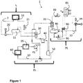
- a thermal management system 1 that comprises a two-phase pump loop (TPPL) 5, a vapor cycle system (VCS) 75, and a thermal energy storage (TES) system 35.
- the various components within each of the TPPL 5, VCS 75, and TES system 35 may be in fluid communication via tubing, hose, or lines through which the corresponding fluid, fluid or fluid mixture, or coolant flows.
- the TTPL 5 may be formed of a fluid loop configured to cool the primary thermal load.
- This fluid loop 5 comprises, consists of, or consists essentially of a fluid 7, a back pressure regulator 25, an evaporator 10, and a condenser 30 that is thermally coupled to the TES system 35.
- the back pressure regulator 25 is configured to manage or control pressure, and thus temperature at an exit of the evaporator in the TPPL 5.
- the evaporator 10 is configured to absorb heat from the apparatus at a near constant temperature. The heat, which is absorbed by the fluid 7 at the evaporator 10, is removed from the TPPL 5 at the condenser 30.
- the TPPL 5 may also comprise a pump 20 configured to cause the fluid 7 to flow through the TPPL 5 and an accumulator 15 to prevent any back flow of the fluid 7 into the condenser 30.
- a pump 20 configured to cause the fluid 7 to flow through the TPPL 5 and an accumulator 15 to prevent any back flow of the fluid 7 into the condenser 30.
- the fluid 7 in the TPPL 5 may be any substance suitable for use in a two-phase pump loop (TPPL) 5.
- the fluid 7 may be any substance having a vapor to fluid transition.
- the fluid 7 may, without limitation, be suitable for use in a coolant and/or refrigeration system.
- a fluid 7 may include, but not be limited to, a chlorofluorocarbon (CFC), a hydrochlorofluorocarbon (HCFC), a hydrofluorocarbon (HFC), difluoromethane, difluoroethane, or a combination thereof.
- the fluid may be R134a, ammonia, carbon dioxide (CO 2 ) or a sub-critical, trans-critical, or super-critical coolant system.
- the fluid or fluid mixture 37 of the TES system 35 provides for thermal energy storage, as well as thermal damping by allowing a high flow capacity pump 40 to change speed and provide cooling from flowing a fluid or fluid mixture 37 from a TES reservoir 50 very quickly.
- the VCS 75 comprises a coolant loop that includes an evaporator 70 thermally coupled with the TES system 35 in order to transfer heat from the TES system 35 to the VSC 75; a coolant 77; a vapor-liquid separator 80 having an inlet, a vapor outlet, and a liquid outlet; and a liquid return valve 96 configured to adjust the flow of the coolant 77 based on the temperature of the coolant 77.
- the VSC 75 further comprises a recuperator 90 having a high pressure and low pressure side that is configured to transfer heat from the high pressure side to the low pressure side; a compressor 99 configured to compress the coolant 77 supplied to the compressor 99 in a vapor state; a gas cooler 85 configured to cool the coolant 77 compressed by the compressor 99; and an expansion valve 93 configured to adjust the flow of the coolant based on pressure in the VCS 75.
- a recuperator 90 having a high pressure and low pressure side that is configured to transfer heat from the high pressure side to the low pressure side
- a compressor 99 configured to compress the coolant 77 supplied to the compressor 99 in a vapor state
- a gas cooler 85 configured to cool the coolant 77 compressed by the compressor 99
- an expansion valve 93 configured to adjust the flow of the coolant based on pressure in the VCS 75.
- the vapor outlet of the vapor-liquid separator 80 includes a means of creating a pressure drop and for mixing a controlled amount of liquid from the liquid outlet with vapor from the vapor outlet.
- a means for creating a pressure drop include, without limitation, a restriction, a length of pipe or tubing, a pipe or a tubing having a cross-sectional area change, a pipe or a tubing including an obstruction, an orifice, a valve, a bent pipe, an automated valve, a venturi valve, and/or any other physical structure that causes a pressure drop on a fluid as the fluid flows through the physical structure.
- the vapor-liquid separator 80 may include any device configured to separate a vapor-liquid mixture into vapor and liquid portions.
- the vapor-liquid separator 80 may be a vessel in which gravity causes the liquid portion to settle to a bottom portion of the vessel and the vapor portion to rise to a top portion of the vessel.
- the vapor-liquid separator 80 may use centrifugal force to drive the liquid portion towards an outer edge of the vessel for removal and the vapor portion may migrate towards a center region of the vessel.
- the vapor-liquid separator 80 may include a level sensor mechanism that monitors a level of the liquid in the vessel. Examples of the vapor-liquid separator may include, without limitation, a low pressure receiver and a flash tank.
- the compressor 99 may be any mechanical device that increases a pressure of a gas by reducing the volume of the gas. This compressor 99 may be used in conjunction with an oil separator when desirable. Examples of the compressor 99 may include but not be limited to any gas compressor, such as a positive displacement compressor, a dynamic compressor, a rotary compressor, a reciprocating compressor, a centrifugal compressor, an axial compressor, and/or any combination thereof.
- the coolant 77 may be any substance suitable for use in a vapor cycle system (VCS) 75.
- VCS vapor cycle system
- the coolant 77 may be any substance suitable for a trans-critical cooling system, super-critical cooling system, and/or a sub-critical cooling system.
- the coolant may include, without limitation, carbon dioxide (CO 2 ), anhydrous ammonia, a halomethane, a haloalkane, a hydrofluorocarbon (HFC), chlorofluorocarbons (CFC), a hydrochlorofluorocarbon (HCFC), any two-phase fluids, and/or a nanofluid.
- the compressor 99 may compress the coolant 77, which is supplied to the compressor 99 in a vapor state.
- the coolant 77 compressed by the compressor 99 may flow to the gas cooler 85.
- the gas cooler 85 may cool the coolant 77 compressed by the compressor 99.
- This cooled coolant 77 subsequently may flow to a recuperator 90, which has a high pressure and low pressure side.
- the recuperator 90 may include a heat exchanger that transfers heat from the coolant 77 on the high pressure side to the coolant 77 on the low pressure side.
- the coolant 77 that exits the gas cooler 85 may be cooled or sub-cooled prior to entering the expansion valve 93.
- the coolant 77 then enters the evaporator 70 wherein the coolant 77 absorbs heat from the TES system 35.
- the coolant 77 that exits the evaporator 70 flows into an inlet of the vapor-liquid separator 80.
- the coolant separates into a liquid and a vapor in the vapor-liquid separator 80.
- the vapor-liquid separator 80 includes both a liquid outlet and a vapor outlet with an inlet of the liquid return valve 96 receiving a portion of the coolant through the liquid outlet.
- the vapor cycle system (VCS) 75 absorbs heat from the TES system 35 and dissipates the heat to air as quickly as it can upon initiation or start-up.
- the VSC 75 will continue to remove heat commensurate with the rated capacity as long as a thermal load is applied.
- the housekeeping thermal load 55 and the one or more thermal loads 60 associated with conditioning, distributing, or converting energy are transferred directly to the fluid or fluid mixture 37 of the TES system at the correct temperature set by the mixing valve 65, and sent to the VCS to be removed. If the housekeeping 55 and one or more other thermal loads 60 are large enough, the VCS 75 can be turned down to manage them continuously.
- the TES reservoir 50 absorbs the heat load until the required temperature can no longer be delivered and the VCS 75 must cycle on to cool the TES system 35.
- the lower the temperature of the TES reservoir 50 the longer the VCS 75 will have between cycles for a given heat load.
- the fluid or fluid mixture 77 effluent from the condenser 30 in the TES system 35 is mixed with the overflow from cooling the housekeeping 55 and one or more thermal loads 60 associated with conditioning, distributing, or converting energy and sent to the VCS 75 to be cooled.
- the TES system 35 comprises a condenser 30 thermally coupled to the TPPL 5 that is configured to transfer heat from the TPPL 5 to the TES system 35.
- the TES system 35 further comprises a fluid or fluid mixture 37 that flows throughout the TES system 35.
- the TES system 35 also comprises a thermal energy storage (TES) reservoir 50 configured to contain a portion of the fluid or fluid mixture 37; a high capacity pump 40, and an evaporator 70.
- the pump 40 is configured to draw a portion of the fluid or fluid mixture 47 from the thermal energy storage reservoir 50 in order to provide thermal damping or cooling across the condenser 30.
- the evaporator 70 which is thermally coupled to the VCS 75, is configured to transfer heat from the TES system 35 to the VCS 75.
- the fluid or fluid mixture 37 may comprise, but not be limited to, a mixture of water with any fluid that is soluble, dispersible, or miscible with the water.
- a fluid or fluid mixture includes but are not limited to, water-ethylene glycol (EGW), water-propylene glycol (PGW), water-glycerol, and water-alcohol.
- the fluid or fluid mixture is a mixture of water and propylene glycol (PGW).
- the TES system 35 may further comprise one or more sources of at least one of the housekeeping thermal load 55 or the one or more thermal loads 60 associated with conditioning, distributing, or converting energy, as well as a second pump 45 and a mixing valve 65 coupled to the TES reservoir 50 and a second pump outlet flow.
- the second pump 45 has a lower flow capacity than the first pump 40. This second pump 45 is configured to draw a portion of the fluid or fluid mixture 37 from the TES reservoir 50 to provide cooling by the transfer of at least one of the housekeeping 55 or the one or more thermal loads 60 associated with conditioning, distributing, or converting energy into the fluid or fluid mixture 37.
- the mixing valve 65 is configured to control or regulate temperature by mixing the fluid or fluid mixture 37 drawn by the second pump 45 from the TES reservoir 50 with a portion of the fluid or fluid mixture 37 in which the at least one of the housekeeping 55 or the one or more thermal loads 60 associated with conditioning, distributing, or converting energy have been transferred.
- a portion of the fluid or fluid mixture 37 after transfer of the thermal load from at least one of the housekeeping 55 and the one or more thermal loads 60 associated with conditioning, distributing, or converting energy is mixed with a portion of the fluid or fluid mixture 37 in which the heat from the TPPL 5 at the condenser 30 has been transferred with the combined portions of the fluid or fluid mixture 37 being sent to the evaporator 70 that is thermally coupled to the VCS 75.
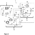
- the VCS 75 may comprise a second evaporator 72 that is thermally coupled to the TES system 35.
- the TES system 35 separates the effluent from the secondary thermal load, e.g., HEL housekeeping 55 and/or thermal loads 60 associated with conditioning, distributing, or converting energy, from the primary thermal load transferred from the TPPL 5 through the condenser 30 to the TES system 35.
- the TES system 35 sends the primary and secondary heat loads to the VCS 75 through separate evaporators 70, 72, respectively. This may be beneficial when the VCS system is optimized to manage the secondary lower heat load condition and a significant difference in coolant temperatures exists between the apparatus (e.g., high-energy laser, HEL) and the housekeeping/conditioning/distributing/energy-converting thermal loads.
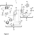
- the number of pumps in the TES system 35 may be reduced to a single pump 40 when desirable. This represents a reduction from two (2) pumps 40, 45 in the TES system 35 as shown in Figure 1 to one (1) pump 40. In this embodiment, the overall footprint or size of the thermal energy storage (TES) system may be reduced.
- TES thermal energy storage
- the one (1) pump 40 configuration may be further modified to comprise a by-pass valve 67 located prior to the condenser 30 and the housekeeping 55 and/or one or more thermal loads 60 associated with conditioning, distributing, or converting energy.
- This by-pass valve 67 may be configured to manage the flow of the fluid or fluid mixture 37 through the condenser 30 and the housekeeping/power electronics loads 55, 66.
- the benefit of this configuration resides in that the return temperature to the evaporator 70 thermally coupled to the VCS 75 will be higher and require a smaller heat exchanger and/or less power to run the VCS 75.
- the evaporator 70 used in conjunction with the VCS 75 may be made smaller by selecting appropriate materials for its construction without exceeding the scope of the present disclosure. More specifically, the important features of this evaporator 70 include the ability to transfer heat, the evacuation of any evaporated liquid, and the containment of pressure.
- a diffusion-bonded structure such as applied to the design and construction of turbine airfoils may be used to form the evaporator 70.
- a diffusion-bonded structure includes complex heat transfer and fluid flow passages. The rules, tools, and manufacturing techniques employed in designing actively cooled turbines directly applies to the problem of providing for the cooling of an apparatus - with the addition of two-phase heat transfer and pressure drop calculations.
- the thermal energy storage (TES) system 35 of the present disclosure may be configured to deliver a uniform pressure (and resulting temperature) to the evaporator 70.
- a control system that monitors and controls one or more aspects of the thermal management system 1, including but not limited to, pump speed, valve setting, VCS compressor speed, gas cooler fan speed, liquid pump speed, high side pressure, and superheat delivered to VCS compressor is envisioned to be included in the scope of the present disclosure.
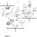
- a mixing valve 69 may be incorporated into the TES system 35 that has a single pump 40 as previously shown in Figure 3 .
- This mixing valve 69 may be located prior to the condenser 30 and after the TES reservoir 50.
- the mixing valve 69 may be in communication with the TES reservoir 50 and a pump outlet flow.
- the incorporation of this mixing valve 69 into the TES system 35 allows for the inlet temperature to the condenser 30 to be at a higher temperature and therefore more fluid or fluid mixture 37 can flow through the condenser 70 without overcooling the TPPL 5.
- the incorporation of a mixing valve 69 into the TES system 35 is useful when the pump 40 needs to operate at a lower speed.
- this mixing valve 69 provides a means of quickly controlling the amount of cooling in the TPPL 5 without having to reduce the speed of the pump.
- the temperature set point associated with the mixing valve 69 can be changed.
- the primary heat load transferred from the TPPL 5 to the TES system 35 across the condenser 30 and the secondary heat loads 60, 55 may be placed in series.
- the primary and secondary heat loads in series, the amount of the fluid or fluid mixture 37 that needs to flow through the TES system 35 is reduced.
- the end-result of this configuration is that a smaller evaporator 70 thermally coupled with the VCS 75, a smaller pump 40, and/or a smaller diameter pipe or line through which the fluid or fluid mixture 37 flows may be incorporated into the TES system 35.
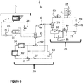
- the temperature set point associated with the mixing valve 69 should not be set so low that the flow of the fluid or fluid mixture 37 going through the housekeeping 55 thermal load and the one or more thermal loads 60 associated with conditioning, distributing, or converting energy falls below a predetermined minimum or lower limit.
- the TES system 35 as shown in Figure 6 may further comprise a by-pass valve 67 as previously described in Figure 4 .
- the fluid or fluid mixture 37 that absorbs the housekeeping 55 and the one or more thermal loads 60 associated with conditioning, distributing, or converting energy may be used as the "cold" input to the second mixing valve 69.
- the by-pass valve 67 ensures that this portion of the TES system 35 remains cold enough to use as the cold input.
- the pump 40 operates at a variable speed in order to maintain the right temperature within the high and low extremes.
- the end-result associated with this scenario is a reduction in the overall need for thermal energy storage over an extended period of operation.
Landscapes
- Engineering & Computer Science (AREA)
- Physics & Mathematics (AREA)
- Mechanical Engineering (AREA)
- Thermal Sciences (AREA)
- General Engineering & Computer Science (AREA)
- Chemical & Material Sciences (AREA)
- Chemical Kinetics & Catalysis (AREA)
- Air Conditioning Control Device (AREA)
Claims (11)
- Système de gestion thermique (1) destiné à réguler la dissipation de multiples charges thermiques durant le fonctionnement d'un appareil, le système de gestion thermique comprenant :un appareil devant être maintenu à température constante ;de multiples charges thermiques comprenant une charge thermique primaire sous forme de chaleur provenant de l'appareil et une charge thermique secondaire sous forme d'au moins l'une d'une charge thermique d'entretien (55) ou d'une ou de plusieurs charges thermiques (60) associées au conditionnement, à la distribution, ou à la conversion d'énergie ; lesdites charges primaire et secondaire étant à des températures différentes, chacune étant choisie indépendamment pour être en régime transitoire ou stable ; etune boucle de pompe à deux phases, TPPL (5) ; un système de cycle de vapeur, VCS (75) ; et un système de stockage d'énergie thermique, TES (35), ladite TPPL, ledit VCS et ledit système TES étant intégrés ensemble pour maintenir l'appareil à une température constante,ladite TPPL étant conçue pour retirer la chaleur de l'appareil et comprenant : une boucle de fluide conçue pour assurer le refroidissement de la charge thermique principale, la boucle de fluide comprenant un fluide (7) ; un évaporateur (10) conçu pour absorber la chaleur de l'appareil à une température presque constante ; et un régulateur de contre-pression (25) conçu pour commander la pression et la température au niveau d'une sortie dans l'évaporateur ;ledit système TES étant conçu pour fournir un stockage d'énergie thermique pour toutes les multiples charges thermiques ou certaines d'entre elles et une régulation de température à au moins l'une des multiples charges thermiques et comprenant : un condenseur (30) couplé thermiquement à la TPPL qui est conçu pour transférer de la chaleur de la TPPL vers le système TES ; un mélange fluide-eau ou de fluides (37) qui s'écoule à travers tout le système TES, ledit fluide étant soluble, dispersible ou miscible avec l'eau ; un réservoir TES (50) conçu pour contenir une partie du fluide ou du mélange de fluides ; une ou plusieurs sources de l'au moins une de la charge thermique d'entretien (55) ou de la ou des charges thermiques (60) associées au conditionnement, à la distribution ou à la conversion d'énergie ; une pompe (40) commandée pour aspirer une partie du fluide ou du mélange de fluides du réservoir TES afin de fournir un amortissement thermique ou un refroidissement à travers le condenseur ; une soupape mélangeuse (65) couplée au réservoir TES et à un flux de sortie de pompe, la soupape mélangeuse étant commandée pour réguler la température en mélangeant une partie du fluide ou du mélange de fluides aspiré du réservoir TES par la pompe avec une partie du fluide ou du mélange de fluides au niveau de la sortie de la pompe ; et un évaporateur (70) couplé thermiquement au VCS qui est conçu pour transférer la chaleur du système TES au VCS ;une partie du fluide ou du mélange de fluides après le transfert de la charge thermique de l'au moins une de la charge thermique d'entretien ou des charges thermiques associées au conditionnement, à la distribution ou à la conversion de l'énergie étant mélangée avec une partie du fluide ou du mélange de fluides dans laquelle la chaleur provenant de la TPPL au niveau du condenseur a été transférée, les parties combinées du fluide ou du mélange de fluides étant envoyées à l'évaporateur couplé thermiquement au VCS ; et ledit VCS étant conçu pour transférer de la chaleur à l'environnement.
- Système de gestion thermique selon la revendication 1, ledit VCS (75) comprenant une boucle de fluide de refroidissement, la boucle de fluide de refroidissement comprenant un fluide de refroidissement (77) ; un séparateur vapeur-liquide (80) possédant une entrée, une sortie de vapeur et une sortie de liquide ; une soupape de retour de liquide (96) conçue pour régler le flux du fluide de refroidissement sur la base de la température du fluide de refroidissement ; un récupérateur (90) possédant un côté haute pression et un côté basse pression qui est conçu pour transférer la chaleur du côté haute pression vers le côté basse pression ; un compresseur (99) conçu pour comprimer le fluide de refroidissement fourni au compresseur à l'état de vapeur ; un refroidisseur de gaz (85) conçu pour refroidir le fluide de refroidissement comprimé par le compresseur ; et une soupape de détente (93) conçue pour maintenir la pression en amont de la soupape de détente ;
ladite sortie de vapeur du séparateur vapeur-liquide comprenant un moyen de création d'une chute de pression et destiné à mélanger une quantité commandée de liquide provenant de la sortie de liquide avec de la vapeur provenant de la sortie de vapeur. - Système de gestion thermique selon la revendication 1, ledit système TES comprenant en outre :
une seconde pompe (45), la seconde pompe étant commandée pour faire circuler le débit souhaité à travers la charge thermique d'entretien ou les charges thermiques associées au conditionnement, à la distribution ou à la conversion de l'énergie afin que le fluide ou le mélange de fluides assure le refroidissement par le transfert d'au moins l'une des charges d'entretien ou thermiques associées au conditionnement, à la distribution ou à la conversion d'énergie dans le fluide ou le mélange de fluides. - Système de gestion thermique selon la revendication 1, ledit système TES comprenant en outre :une seconde pompe (45), la seconde pompe possédant une capacité de flux inférieure à celle de la première pompe, la seconde pompe étant commandée pour aspirer du réservoir TES une partie du fluide ou du mélange de fluides pour assurer le refroidissement par le transfert d'au moins l'une des charges d'entretien ou thermiques associées au conditionnement, à la distribution ou à la conversion d'énergie dans le fluide ou le mélange de fluides ; etun second évaporateur (72) couplé thermiquement au VCS qui est conçu pour transférer une ou plusieurs charges d'entretien et thermiques électroniques de puissance du système TES au VCS séparément du transfert de chaleur au VCS au niveau de l'évaporateur à partir de la partie du mélange d'eau dans lequel la chaleur de la TPPL au niveau du condenseur a été transférée.
- Système de gestion thermique selon la revendication 1, ledit système TES comprenant en outre une soupape de dérivation (67) conçue pour commander le flux du fluide ou du mélange de fluides à travers le condenseur à haute énergie et autour de l'au moins une de la charge thermique d'entretien ou de la charge thermique associée au conditionnement, à la distribution ou à la conversion d'énergie, ou ledit système TES comprenant en outre une seconde soupape mélangeuse (69), la seconde soupape mélangeuse étant positionnée avant le condenseur et conçue pour commander la quantité de refroidissement dans la TPPL sans avoir à régler la vitesse de la pompe, et/ou la seconde soupape mélangeuse étant positionnée avant le condenseur et dans un endroit qui place la charge thermique à haute énergie en série avec la ou les charge thermique d'entretien et charge thermique associée au conditionnement, à la distribution ou à la conversion de l'énergie.
- Système de gestion thermique selon la revendication 5, ledit système TES comprenant en outre une vanne de dérivation (67) utilisée pour commander le flux du fluide ou du mélange de fluides avant la seconde soupape de mélange afin de garantir que le fluide ou le mélange de fluides n'est pas au-dessus d'une température prédéfinie après que la ou les charge thermique d'entretien et charge thermique associée au conditionnement, à la distribution ou à la conversion de l'énergie aient été transférées dans le fluide ou le mélange de fluides ;
ladite pompe fonctionnant à une vitesse variable afin de maintenir la température prédéfinie. - Système de gestion thermique selon la revendication 1, ledit fluide dans la TPPL et ledit fluide de refroidissement dans le VCS étant choisis indépendamment pour être du R134a, de l'ammoniac ou du CO2 transcritique, et ledit fluide ou ledit mélange de fluides dans le système TES étant un mélange d'eau et d'éthylène glycol, de propylène glycol, de glycérol ou d'un alcool.
- Système de gestion thermique selon l'une quelconque des revendications précédentes, ladite charge thermique étant variable et possédant une limite de température minimale ;
ledit système TES étant contraint de ne pas dépasser la limite de température minimale. - Système de gestion thermique selon l'une quelconque des revendications 1 à 8, ledit appareil étant une diode électroluminescente (DEL), un circuit analogique, un circuit numérique, un ordinateur, un serveur, une ferme de serveurs, un centre de données, un circuit hôtelier, un véhicule, un aéronef, une arme à énergie dirigée, un laser à haute énergie (HEL), une arme à plasma, un canon électrique, un générateur de micro-ondes, un dispositif alimenté par impulsions, une liaison montante par satellite ou un moteur électrique.
- Procédé de régulation de la dissipation de multiples charges thermiques durant le fonctionnement d'un appareil, le procédé comprenant :la fourniture d'un système de gestion thermique (91) selon la revendication 1 ;le retrait de la chaleur de l'appareil en la transférant vers la TPPL ;le transfert de chaleur de la TPPL au système TES ; le système TES assurant le stockage de l'énergie thermique et la régulation de la température en vue du refroidissement des multiples charges thermiques ; les multiples charges thermiques comprenant une charge thermique primaire sous forme de chaleur provenant de l'appareil et une charge thermique secondaire sous la forme d'au moins l'une d'une charge thermique d'entretien ou d'une charge thermique associée au conditionnement, à la distribution ou à la conversion d'énergie ; lesdites charges primaire et secondaire étant à des températures différentes, chacune étant choisie indépendamment pour être en régime transitoire ou stable ;le transfert de chaleur du système TES au VSC ; et le transfert de chaleur du VSC à l'environnement.
- Procédé selon la revendication 10, ledit appareil étant une diode électroluminescente (DEL), un circuit analogique, un circuit numérique, un ordinateur, un serveur, une ferme de serveurs, un centre de données, un circuit hôtelier, un véhicule, un aéronef, une arme à énergie dirigée, un laser à haute énergie (HEL), une arme à plasma, un canon électrique, un générateur de micro-ondes, un dispositif alimenté par impulsions, une liaison montante par satellite ou un moteur électrique.
Applications Claiming Priority (2)
| Application Number | Priority Date | Filing Date | Title |
|---|---|---|---|
| US201862656518P | 2018-04-12 | 2018-04-12 | |
| US16/058,224 US10746440B2 (en) | 2018-04-12 | 2018-08-08 | Thermal management system including two-phased pump loop and thermal energy storage |
Publications (2)
| Publication Number | Publication Date |
|---|---|
| EP3553418A1 EP3553418A1 (fr) | 2019-10-16 |
| EP3553418B1 true EP3553418B1 (fr) | 2021-11-10 |
Family
ID=65801880
Family Applications (1)
| Application Number | Title | Priority Date | Filing Date |
|---|---|---|---|
| EP19162234.9A Active EP3553418B1 (fr) | 2018-04-12 | 2019-03-12 | Système de gestion thermique comprenant une boucle de pompe à deux étages et un stockage d'énergie thermique |
Country Status (3)
| Country | Link |
|---|---|
| US (1) | US10746440B2 (fr) |
| EP (1) | EP3553418B1 (fr) |
| CA (1) | CA3037896A1 (fr) |
Families Citing this family (20)
| Publication number | Priority date | Publication date | Assignee | Title |
|---|---|---|---|---|
| WO2019094031A1 (fr) * | 2017-11-10 | 2019-05-16 | Hussmann Corporation | Système de réfrigération de co2 sous-critique utilisant un stockage thermique |
| US11486607B1 (en) | 2018-11-01 | 2022-11-01 | Booz Allen Hamilton Inc. | Thermal management systems for extended operation |
| US11168925B1 (en) | 2018-11-01 | 2021-11-09 | Booz Allen Hamilton Inc. | Thermal management systems |
| US11629890B1 (en) | 2019-12-18 | 2023-04-18 | Booz Allen Hamilton Inc. | Thermal management systems |
| US11732941B1 (en) | 2020-03-26 | 2023-08-22 | Booz Allen Hamilton Inc. | Thermal management systems |
| US11561030B1 (en) | 2020-06-15 | 2023-01-24 | Booz Allen Hamilton Inc. | Thermal management systems |
| US11879678B1 (en) | 2020-06-16 | 2024-01-23 | Booz Allen Hamilton Inc. | Thermal management systems |
| US11692742B1 (en) | 2020-07-02 | 2023-07-04 | Booz Allen Hamilton Inc. | Thermal management systems |
| US11162388B1 (en) | 2020-08-12 | 2021-11-02 | Rolls-Royce North American Technologies Inc. | Thermal management system to cool transient heat loads with low power consumption |
| US11737240B1 (en) | 2020-09-10 | 2023-08-22 | Hamfop Technologies LLC | Heat-activated multiphase fluid-operated pump for electronics waste heat removal |
| US11744042B2 (en) * | 2020-11-06 | 2023-08-29 | Rolls-Royce North American Technologies Inc. | Thermal management system with dual-use serial thermal energy storage for system size reduction |
| US11781817B2 (en) | 2021-06-22 | 2023-10-10 | Booz Allen Hamilton Inc. | Thermal management systems for extended operation |
| US12578127B2 (en) | 2021-07-30 | 2026-03-17 | Ge Energy Power Conversion Technology Limited | Cooling systems |
| US12352475B2 (en) * | 2022-07-01 | 2025-07-08 | Terrence Creswell | Air conditioning system |
| US11988418B2 (en) | 2022-09-14 | 2024-05-21 | Hamilton Sundstrand Corporation | Vapor compression cycle with direct pumped two-phase cooling |
| CN116639267B (zh) * | 2023-04-28 | 2025-11-18 | 上海宇航系统工程研究所 | 一种月球探测载人航天器热管理系统及控制方法 |
| US12460874B2 (en) | 2023-08-03 | 2025-11-04 | United States Of America As Represented By The Secretary Of The Air Force | Two-phase refrigerant pump bladder control system |
| US12578131B2 (en) | 2023-11-10 | 2026-03-17 | Hamilton Sundstrand Corporation | Compressor oil recovery in hybrid VCC pumped two phase loops |
| US12552541B2 (en) | 2023-11-10 | 2026-02-17 | Hamilton Sundstrand Corporation | Thermal management system for future vertical lift aircraft |
| CN119872935B (zh) * | 2025-01-17 | 2025-11-04 | 北京国电高科科技有限公司 | 一种适用于卫星设备的应急系统及方法 |
Family Cites Families (7)
| Publication number | Priority date | Publication date | Assignee | Title |
|---|---|---|---|---|
| US6631621B2 (en) * | 2001-07-03 | 2003-10-14 | Thermo King Corporation | Cryogenic temperature control apparatus and method |
| US6948556B1 (en) | 2003-11-12 | 2005-09-27 | Anderson William G | Hybrid loop cooling of high powered devices |
| MXPA06013529A (es) | 2004-05-25 | 2007-08-21 | Ice Energy Inc | Sistema de enfriamiento y almacenamiento de energia termica basado en refrigerante con capacidad mejorada de intercambio de calor. |
| US7421846B2 (en) | 2004-08-18 | 2008-09-09 | Ice Energy, Inc. | Thermal energy storage and cooling system with gravity fed secondary refrigerant isolation |
| WO2009070732A1 (fr) | 2007-11-28 | 2009-06-04 | Ice Energy, Inc. | Système de stockage et de refroidissement d'énergie thermique avec de multiples boucles de refroidissement utilisant une bobine d'évaporateur commune |
| US20090293507A1 (en) * | 2008-05-28 | 2009-12-03 | Ice Energy, Inc. | Thermal energy storage and cooling system with isolated evaporator coil |
| US10184699B2 (en) * | 2014-10-27 | 2019-01-22 | Ebullient, Inc. | Fluid distribution unit for two-phase cooling system |
-
2018
- 2018-08-08 US US16/058,224 patent/US10746440B2/en active Active
-
2019
- 2019-03-12 EP EP19162234.9A patent/EP3553418B1/fr active Active
- 2019-03-22 CA CA3037896A patent/CA3037896A1/fr active Pending
Also Published As
| Publication number | Publication date |
|---|---|
| US20190316817A1 (en) | 2019-10-17 |
| EP3553418A1 (fr) | 2019-10-16 |
| US10746440B2 (en) | 2020-08-18 |
| CA3037896A1 (fr) | 2019-10-12 |
Similar Documents
| Publication | Publication Date | Title |
|---|---|---|
| EP3553418B1 (fr) | Système de gestion thermique comprenant une boucle de pompe à deux étages et un stockage d'énergie thermique | |
| EP3553420B1 (fr) | Régulation rigoureuse de la température sous une charge thermique à l'aide d'une boucle de pompage biphasée, augmentée en option par un cycle de compression de vapeur | |
| US11744042B2 (en) | Thermal management system with dual-use serial thermal energy storage for system size reduction | |
| US11162388B1 (en) | Thermal management system to cool transient heat loads with low power consumption | |
| US11892208B2 (en) | Method and apparatus for isothermal cooling | |
| EP3553421B1 (fr) | Système de stockage d'énergie thermique et de rejet de chaleur | |
| US11273925B1 (en) | Thermal management system and method for cooling a hybrid electric aircraft propulsion system | |
| KR101043156B1 (ko) | 고에너지 고체레이저장치용 냉각장치 | |
| US20120312037A1 (en) | Vapor cycle system with de-superheater | |
| EP1380799A2 (fr) | Procédé et dispositif pour refroidir avec un fluide réfrigérant à pression sous-ambiante | |
| EP2073617A2 (fr) | Système et procédé pour contrôler le refroidissement de charges thermiques variables de dispositif générateurs de chaleur | |
| US11530844B2 (en) | System for supporting intermittent fast transient heat loads | |
| EP2000753A2 (fr) | Système et procédé de séparation de composants d'un agent de refroidissement fluide pour refroidir une structure | |
| Mahefkey et al. | Thermal management challenges for future military aircraft power systems | |
| CN105004083A (zh) | 涡轮机和制冷循环装置 | |
| US3881323A (en) | Viscosity regulated cooling system | |
| US20090101311A1 (en) | System and Method for Cooling Using Two Separate Coolants | |
| EP2626653A2 (fr) | Circuit de réfrigération secondaire comprenant un matériau à changement de phase microencapsulée | |
| Hoang et al. | Multiple-evaporator loop heat pipe | |
| Holman et al. | Operational principles of a pump-augmented loop heat pipe with auxiliary evaporators | |
| Ku et al. | Thermal vacuum testing of a miniature Loop Heat Pipe with multiple evaporators and multiple condensers | |
| CA3045263A1 (fr) | Regulation rigoureuse de la temperature sous une charge thermique a l`aide d`une boucle de pompage biphasee, augmentee en option par un cycle de compression de vapeur | |
| Homitz et al. | Evaluation of a vapor-compression thermal management system for reliability while operating under thermal transients |
Legal Events
| Date | Code | Title | Description |
|---|---|---|---|
| PUAI | Public reference made under article 153(3) epc to a published international application that has entered the european phase |
Free format text: ORIGINAL CODE: 0009012 |
|
| STAA | Information on the status of an ep patent application or granted ep patent |
Free format text: STATUS: THE APPLICATION HAS BEEN PUBLISHED |
|
| AK | Designated contracting states |
Kind code of ref document: A1 Designated state(s): AL AT BE BG CH CY CZ DE DK EE ES FI FR GB GR HR HU IE IS IT LI LT LU LV MC MK MT NL NO PL PT RO RS SE SI SK SM TR |
|
| AX | Request for extension of the european patent |
Extension state: BA ME |
|
| STAA | Information on the status of an ep patent application or granted ep patent |
Free format text: STATUS: REQUEST FOR EXAMINATION WAS MADE |
|
| 17P | Request for examination filed |
Effective date: 20200403 |
|
| RBV | Designated contracting states (corrected) |
Designated state(s): AL AT BE BG CH CY CZ DE DK EE ES FI FR GB GR HR HU IE IS IT LI LT LU LV MC MK MT NL NO PL PT RO RS SE SI SK SM TR |
|
| GRAP | Despatch of communication of intention to grant a patent |
Free format text: ORIGINAL CODE: EPIDOSNIGR1 |
|
| STAA | Information on the status of an ep patent application or granted ep patent |
Free format text: STATUS: GRANT OF PATENT IS INTENDED |
|
| GRAJ | Information related to disapproval of communication of intention to grant by the applicant or resumption of examination proceedings by the epo deleted |
Free format text: ORIGINAL CODE: EPIDOSDIGR1 |
|
| STAA | Information on the status of an ep patent application or granted ep patent |
Free format text: STATUS: REQUEST FOR EXAMINATION WAS MADE |
|
| RIC1 | Information provided on ipc code assigned before grant |
Ipc: F25B 9/00 20060101AFI20210714BHEP Ipc: F25B 23/00 20060101ALI20210714BHEP Ipc: F25B 25/00 20060101ALI20210714BHEP Ipc: F25B 40/00 20060101ALI20210714BHEP |
|
| GRAP | Despatch of communication of intention to grant a patent |
Free format text: ORIGINAL CODE: EPIDOSNIGR1 |
|
| STAA | Information on the status of an ep patent application or granted ep patent |
Free format text: STATUS: GRANT OF PATENT IS INTENDED |
|
| INTG | Intention to grant announced |
Effective date: 20210810 |
|
| RIN1 | Information on inventor provided before grant (corrected) |
Inventor name: ACIUS, ARIC Inventor name: SNYDER, DOUGLAS Inventor name: SPANGLER, BRIAN Inventor name: RUBEL, KEN Inventor name: HEAD, MICHAEL Inventor name: DONOVAN, ERIC |
|
| INTC | Intention to grant announced (deleted) | ||
| INTG | Intention to grant announced |
Effective date: 20210902 |
|
| GRAS | Grant fee paid |
Free format text: ORIGINAL CODE: EPIDOSNIGR3 |
|
| GRAA | (expected) grant |
Free format text: ORIGINAL CODE: 0009210 |
|
| STAA | Information on the status of an ep patent application or granted ep patent |
Free format text: STATUS: THE PATENT HAS BEEN GRANTED |
|
| AK | Designated contracting states |
Kind code of ref document: B1 Designated state(s): AL AT BE BG CH CY CZ DE DK EE ES FI FR GB GR HR HU IE IS IT LI LT LU LV MC MK MT NL NO PL PT RO RS SE SI SK SM TR |
|
| REG | Reference to a national code |
Ref country code: GB Ref legal event code: FG4D |
|
| REG | Reference to a national code |
Ref country code: AT Ref legal event code: REF Ref document number: 1446438 Country of ref document: AT Kind code of ref document: T Effective date: 20211115 Ref country code: CH Ref legal event code: EP |
|
| REG | Reference to a national code |
Ref country code: DE Ref legal event code: R096 Ref document number: 602019009052 Country of ref document: DE |
|
| REG | Reference to a national code |
Ref country code: IE Ref legal event code: FG4D |
|
| REG | Reference to a national code |
Ref country code: LT Ref legal event code: MG9D |
|
| REG | Reference to a national code |
Ref country code: NL Ref legal event code: MP Effective date: 20211110 |
|
| REG | Reference to a national code |
Ref country code: AT Ref legal event code: MK05 Ref document number: 1446438 Country of ref document: AT Kind code of ref document: T Effective date: 20211110 |
|
| PG25 | Lapsed in a contracting state [announced via postgrant information from national office to epo] |
Ref country code: RS Free format text: LAPSE BECAUSE OF FAILURE TO SUBMIT A TRANSLATION OF THE DESCRIPTION OR TO PAY THE FEE WITHIN THE PRESCRIBED TIME-LIMIT Effective date: 20211110 Ref country code: LT Free format text: LAPSE BECAUSE OF FAILURE TO SUBMIT A TRANSLATION OF THE DESCRIPTION OR TO PAY THE FEE WITHIN THE PRESCRIBED TIME-LIMIT Effective date: 20211110 Ref country code: FI Free format text: LAPSE BECAUSE OF FAILURE TO SUBMIT A TRANSLATION OF THE DESCRIPTION OR TO PAY THE FEE WITHIN THE PRESCRIBED TIME-LIMIT Effective date: 20211110 Ref country code: BG Free format text: LAPSE BECAUSE OF FAILURE TO SUBMIT A TRANSLATION OF THE DESCRIPTION OR TO PAY THE FEE WITHIN THE PRESCRIBED TIME-LIMIT Effective date: 20220210 Ref country code: AT Free format text: LAPSE BECAUSE OF FAILURE TO SUBMIT A TRANSLATION OF THE DESCRIPTION OR TO PAY THE FEE WITHIN THE PRESCRIBED TIME-LIMIT Effective date: 20211110 |
|
| PG25 | Lapsed in a contracting state [announced via postgrant information from national office to epo] |
Ref country code: IS Free format text: LAPSE BECAUSE OF FAILURE TO SUBMIT A TRANSLATION OF THE DESCRIPTION OR TO PAY THE FEE WITHIN THE PRESCRIBED TIME-LIMIT Effective date: 20220310 Ref country code: SE Free format text: LAPSE BECAUSE OF FAILURE TO SUBMIT A TRANSLATION OF THE DESCRIPTION OR TO PAY THE FEE WITHIN THE PRESCRIBED TIME-LIMIT Effective date: 20211110 Ref country code: PT Free format text: LAPSE BECAUSE OF FAILURE TO SUBMIT A TRANSLATION OF THE DESCRIPTION OR TO PAY THE FEE WITHIN THE PRESCRIBED TIME-LIMIT Effective date: 20220310 Ref country code: PL Free format text: LAPSE BECAUSE OF FAILURE TO SUBMIT A TRANSLATION OF THE DESCRIPTION OR TO PAY THE FEE WITHIN THE PRESCRIBED TIME-LIMIT Effective date: 20211110 Ref country code: NO Free format text: LAPSE BECAUSE OF FAILURE TO SUBMIT A TRANSLATION OF THE DESCRIPTION OR TO PAY THE FEE WITHIN THE PRESCRIBED TIME-LIMIT Effective date: 20220210 Ref country code: NL Free format text: LAPSE BECAUSE OF FAILURE TO SUBMIT A TRANSLATION OF THE DESCRIPTION OR TO PAY THE FEE WITHIN THE PRESCRIBED TIME-LIMIT Effective date: 20211110 Ref country code: LV Free format text: LAPSE BECAUSE OF FAILURE TO SUBMIT A TRANSLATION OF THE DESCRIPTION OR TO PAY THE FEE WITHIN THE PRESCRIBED TIME-LIMIT Effective date: 20211110 Ref country code: HR Free format text: LAPSE BECAUSE OF FAILURE TO SUBMIT A TRANSLATION OF THE DESCRIPTION OR TO PAY THE FEE WITHIN THE PRESCRIBED TIME-LIMIT Effective date: 20211110 Ref country code: GR Free format text: LAPSE BECAUSE OF FAILURE TO SUBMIT A TRANSLATION OF THE DESCRIPTION OR TO PAY THE FEE WITHIN THE PRESCRIBED TIME-LIMIT Effective date: 20220211 Ref country code: ES Free format text: LAPSE BECAUSE OF FAILURE TO SUBMIT A TRANSLATION OF THE DESCRIPTION OR TO PAY THE FEE WITHIN THE PRESCRIBED TIME-LIMIT Effective date: 20211110 |
|
| PG25 | Lapsed in a contracting state [announced via postgrant information from national office to epo] |
Ref country code: SM Free format text: LAPSE BECAUSE OF FAILURE TO SUBMIT A TRANSLATION OF THE DESCRIPTION OR TO PAY THE FEE WITHIN THE PRESCRIBED TIME-LIMIT Effective date: 20211110 Ref country code: SK Free format text: LAPSE BECAUSE OF FAILURE TO SUBMIT A TRANSLATION OF THE DESCRIPTION OR TO PAY THE FEE WITHIN THE PRESCRIBED TIME-LIMIT Effective date: 20211110 Ref country code: RO Free format text: LAPSE BECAUSE OF FAILURE TO SUBMIT A TRANSLATION OF THE DESCRIPTION OR TO PAY THE FEE WITHIN THE PRESCRIBED TIME-LIMIT Effective date: 20211110 Ref country code: EE Free format text: LAPSE BECAUSE OF FAILURE TO SUBMIT A TRANSLATION OF THE DESCRIPTION OR TO PAY THE FEE WITHIN THE PRESCRIBED TIME-LIMIT Effective date: 20211110 Ref country code: DK Free format text: LAPSE BECAUSE OF FAILURE TO SUBMIT A TRANSLATION OF THE DESCRIPTION OR TO PAY THE FEE WITHIN THE PRESCRIBED TIME-LIMIT Effective date: 20211110 Ref country code: CZ Free format text: LAPSE BECAUSE OF FAILURE TO SUBMIT A TRANSLATION OF THE DESCRIPTION OR TO PAY THE FEE WITHIN THE PRESCRIBED TIME-LIMIT Effective date: 20211110 |
|
| REG | Reference to a national code |
Ref country code: DE Ref legal event code: R097 Ref document number: 602019009052 Country of ref document: DE |
|
| PLBE | No opposition filed within time limit |
Free format text: ORIGINAL CODE: 0009261 |
|
| STAA | Information on the status of an ep patent application or granted ep patent |
Free format text: STATUS: NO OPPOSITION FILED WITHIN TIME LIMIT |
|
| 26N | No opposition filed |
Effective date: 20220811 |
|
| PG25 | Lapsed in a contracting state [announced via postgrant information from national office to epo] |
Ref country code: MC Free format text: LAPSE BECAUSE OF FAILURE TO SUBMIT A TRANSLATION OF THE DESCRIPTION OR TO PAY THE FEE WITHIN THE PRESCRIBED TIME-LIMIT Effective date: 20211110 Ref country code: AL Free format text: LAPSE BECAUSE OF FAILURE TO SUBMIT A TRANSLATION OF THE DESCRIPTION OR TO PAY THE FEE WITHIN THE PRESCRIBED TIME-LIMIT Effective date: 20211110 |
|
| REG | Reference to a national code |
Ref country code: CH Ref legal event code: PL |
|
| PG25 | Lapsed in a contracting state [announced via postgrant information from national office to epo] |
Ref country code: SI Free format text: LAPSE BECAUSE OF FAILURE TO SUBMIT A TRANSLATION OF THE DESCRIPTION OR TO PAY THE FEE WITHIN THE PRESCRIBED TIME-LIMIT Effective date: 20211110 |
|
| REG | Reference to a national code |
Ref country code: BE Ref legal event code: MM Effective date: 20220331 |
|
| PG25 | Lapsed in a contracting state [announced via postgrant information from national office to epo] |
Ref country code: LU Free format text: LAPSE BECAUSE OF NON-PAYMENT OF DUE FEES Effective date: 20220312 Ref country code: LI Free format text: LAPSE BECAUSE OF NON-PAYMENT OF DUE FEES Effective date: 20220331 Ref country code: IE Free format text: LAPSE BECAUSE OF NON-PAYMENT OF DUE FEES Effective date: 20220312 Ref country code: CH Free format text: LAPSE BECAUSE OF NON-PAYMENT OF DUE FEES Effective date: 20220331 |
|
| PG25 | Lapsed in a contracting state [announced via postgrant information from national office to epo] |
Ref country code: BE Free format text: LAPSE BECAUSE OF NON-PAYMENT OF DUE FEES Effective date: 20220331 |
|
| PG25 | Lapsed in a contracting state [announced via postgrant information from national office to epo] |
Ref country code: IT Free format text: LAPSE BECAUSE OF FAILURE TO SUBMIT A TRANSLATION OF THE DESCRIPTION OR TO PAY THE FEE WITHIN THE PRESCRIBED TIME-LIMIT Effective date: 20211110 |
|
| P01 | Opt-out of the competence of the unified patent court (upc) registered |
Effective date: 20230528 |
|
| GBPC | Gb: european patent ceased through non-payment of renewal fee |
Effective date: 20230312 |
|
| PG25 | Lapsed in a contracting state [announced via postgrant information from national office to epo] |
Ref country code: GB Free format text: LAPSE BECAUSE OF NON-PAYMENT OF DUE FEES Effective date: 20230312 |
|
| PG25 | Lapsed in a contracting state [announced via postgrant information from national office to epo] |
Ref country code: GB Free format text: LAPSE BECAUSE OF NON-PAYMENT OF DUE FEES Effective date: 20230312 |
|
| PG25 | Lapsed in a contracting state [announced via postgrant information from national office to epo] |
Ref country code: MK Free format text: LAPSE BECAUSE OF FAILURE TO SUBMIT A TRANSLATION OF THE DESCRIPTION OR TO PAY THE FEE WITHIN THE PRESCRIBED TIME-LIMIT Effective date: 20211110 Ref country code: CY Free format text: LAPSE BECAUSE OF FAILURE TO SUBMIT A TRANSLATION OF THE DESCRIPTION OR TO PAY THE FEE WITHIN THE PRESCRIBED TIME-LIMIT Effective date: 20211110 |
|
| PG25 | Lapsed in a contracting state [announced via postgrant information from national office to epo] |
Ref country code: HU Free format text: LAPSE BECAUSE OF FAILURE TO SUBMIT A TRANSLATION OF THE DESCRIPTION OR TO PAY THE FEE WITHIN THE PRESCRIBED TIME-LIMIT; INVALID AB INITIO Effective date: 20190312 |
|
| PG25 | Lapsed in a contracting state [announced via postgrant information from national office to epo] |
Ref country code: TR Free format text: LAPSE BECAUSE OF FAILURE TO SUBMIT A TRANSLATION OF THE DESCRIPTION OR TO PAY THE FEE WITHIN THE PRESCRIBED TIME-LIMIT Effective date: 20211110 |
|
| PG25 | Lapsed in a contracting state [announced via postgrant information from national office to epo] |
Ref country code: MT Free format text: LAPSE BECAUSE OF FAILURE TO SUBMIT A TRANSLATION OF THE DESCRIPTION OR TO PAY THE FEE WITHIN THE PRESCRIBED TIME-LIMIT Effective date: 20211110 |
|
| PGFP | Annual fee paid to national office [announced via postgrant information from national office to epo] |
Ref country code: DE Payment date: 20260320 Year of fee payment: 8 |
|
| PGFP | Annual fee paid to national office [announced via postgrant information from national office to epo] |
Ref country code: FR Payment date: 20260323 Year of fee payment: 8 |