EP3553393B1 - Cooking appliance - Google Patents
Cooking appliance Download PDFInfo
- Publication number
- EP3553393B1 EP3553393B1 EP18209696.6A EP18209696A EP3553393B1 EP 3553393 B1 EP3553393 B1 EP 3553393B1 EP 18209696 A EP18209696 A EP 18209696A EP 3553393 B1 EP3553393 B1 EP 3553393B1
- Authority
- EP
- European Patent Office
- Prior art keywords
- water
- water supply
- steam generator
- supply pipe
- water tank
- Prior art date
- Legal status (The legal status is an assumption and is not a legal conclusion. Google has not performed a legal analysis and makes no representation as to the accuracy of the status listed.)
- Active
Links
Images



Classifications
-
- F—MECHANICAL ENGINEERING; LIGHTING; HEATING; WEAPONS; BLASTING
- F24—HEATING; RANGES; VENTILATING
- F24C—DOMESTIC STOVES OR RANGES ; DETAILS OF DOMESTIC STOVES OR RANGES, OF GENERAL APPLICATION
- F24C15/00—Details
- F24C15/32—Arrangements of ducts for hot gases, e.g. in or around baking ovens
- F24C15/322—Arrangements of ducts for hot gases, e.g. in or around baking ovens with forced circulation
- F24C15/327—Arrangements of ducts for hot gases, e.g. in or around baking ovens with forced circulation with air moisturising
-
- A—HUMAN NECESSITIES
- A47—FURNITURE; DOMESTIC ARTICLES OR APPLIANCES; COFFEE MILLS; SPICE MILLS; SUCTION CLEANERS IN GENERAL
- A47J—KITCHEN EQUIPMENT; COFFEE MILLS; SPICE MILLS; APPARATUS FOR MAKING BEVERAGES
- A47J27/00—Cooking-vessels
- A47J27/04—Cooking-vessels for cooking food in steam; Devices for extracting fruit juice by means of steam ; Vacuum cooking vessels
-
- F—MECHANICAL ENGINEERING; LIGHTING; HEATING; WEAPONS; BLASTING
- F22—STEAM GENERATION
- F22B—METHODS OF STEAM GENERATION; STEAM BOILERS
- F22B1/00—Methods of steam generation characterised by form of heating method
- F22B1/28—Methods of steam generation characterised by form of heating method in boilers heated electrically
- F22B1/284—Methods of steam generation characterised by form of heating method in boilers heated electrically with water in reservoirs
- F22B1/285—Methods of steam generation characterised by form of heating method in boilers heated electrically with water in reservoirs the water being fed by a pump to the reservoirs
-
- F—MECHANICAL ENGINEERING; LIGHTING; HEATING; WEAPONS; BLASTING
- F22—STEAM GENERATION
- F22B—METHODS OF STEAM GENERATION; STEAM BOILERS
- F22B37/00—Component parts or details of steam boilers
- F22B37/02—Component parts or details of steam boilers applicable to more than one kind or type of steam boiler
- F22B37/10—Water tubes; Accessories therefor
- F22B37/14—Supply mains, e.g. rising mains, down-comers, in connection with water tubes
- F22B37/141—Supply mains, e.g. rising mains, down-comers, in connection with water tubes involving vertically-disposed water tubes, e.g. walls built-up from vertical tubes
-
- F—MECHANICAL ENGINEERING; LIGHTING; HEATING; WEAPONS; BLASTING
- F22—STEAM GENERATION
- F22D—PREHEATING, OR ACCUMULATING PREHEATED, FEED-WATER FOR STEAM GENERATION; FEED-WATER SUPPLY FOR STEAM GENERATION; CONTROLLING WATER LEVEL FOR STEAM GENERATION; AUXILIARY DEVICES FOR PROMOTING WATER CIRCULATION WITHIN STEAM BOILERS
- F22D11/00—Feed-water supply not provided for in other main groups
- F22D11/02—Arrangements of feed-water pumps
-
- F—MECHANICAL ENGINEERING; LIGHTING; HEATING; WEAPONS; BLASTING
- F24—HEATING; RANGES; VENTILATING
- F24C—DOMESTIC STOVES OR RANGES ; DETAILS OF DOMESTIC STOVES OR RANGES, OF GENERAL APPLICATION
- F24C15/00—Details
- F24C15/003—Details moisturising of air
-
- A—HUMAN NECESSITIES
- A47—FURNITURE; DOMESTIC ARTICLES OR APPLIANCES; COFFEE MILLS; SPICE MILLS; SUCTION CLEANERS IN GENERAL
- A47J—KITCHEN EQUIPMENT; COFFEE MILLS; SPICE MILLS; APPARATUS FOR MAKING BEVERAGES
- A47J27/00—Cooking-vessels
- A47J27/04—Cooking-vessels for cooking food in steam; Devices for extracting fruit juice by means of steam ; Vacuum cooking vessels
- A47J2027/043—Cooking-vessels for cooking food in steam; Devices for extracting fruit juice by means of steam ; Vacuum cooking vessels for cooking food in steam
Definitions
- the present specification relates to a cooking appliance.
- the cooking appliance refers to an appliance for cooking food using heat of a heating source.
- the cooking appliance may include a heating source for heating food contained in a cooking chamber.
- the cooking appliance may include at least one or a plurality of heating sources.
- the one or more heating sources may include an electric heater, a magnetron, a steam generator, etc.
- Korean Patent Registration Publication No. 10-0624080 discloses a heating cooker including a main body having a cooking chamber formed therein and a steam generator for supplying steam into the cooking chamber.
- a water tank is provided at an upper side of the cooking chamber to be detached from a front surface of the main body in the form of a drawer, and the steam generator is disposed at the back side of the cooking chamber to receive water from the water tank through a water supply pipe.
- a water supply control valve is provided on the water supply pipe to control flow of water.
- WO 2005/015088 A1 relates to a cooking device capable of continuously feeding steam to a heating chamber over an extended time period despite its low electric power consumption and a small structure, and a method of driving the cooking device.
- US 2016/061490 A1 relates to a cooking appliance having an improved structure in which superheated steam is capable of being used during a cooking operation.
- the cooking appliance comprises a water tank and a pump are disposed between the main body and the cover and the steam generator is disposed at an outer edge of the rear frame of the main body below the water tank and the water pump.
- a water supply pump is used as the water supply control valve, the water of the water tank is supplied to the steam generator when the water supply pump operates, and the water supply pump is stopped when water supply is completed.
- the water tank is located at the upper side of the steam generator, even when operation of the water supply pump is stopped, negative pressure may be generated, thereby supplying the water of the water tank to the steam generator.
- the present embodiment provides a cooking appliance capable of preventing water from being additionally supplied to a steam generator due to negative pressure, in particular in a state in which a water supply pump is stopped after water is supplied to the steam generator.
- the present embodiment provides a cooking appliance capable of preventing water discharged from a water tank from being leaked after a water supply pump is stopped.
- a cooking appliance includes a main body including a cooking chamber, a steam generator including a steam heater for generating steam for heating food contained in the cooking chamber, a water tank configured to store water to be supplied to the steam generator, a water supply pump configured to operate in order to supply water of the water tank to the steam generator, a first water supply pipe connected to the water tank, a connector connected to the first water supply pipe, a second water supply pipe connected to the connector and connected to the steam generator, and a branch pipe connected to the connector.
- the water tank is located at a position higher than the steam generator, and the connector and the branch pipe are located at positions higher than the water tank.
- the connector may be formed in a T shape.
- a portion of the first water supply pipe may be located at a position higher than the water tank.
- a portion of the second water supply pipe may be located at a position higher than the water tank.
- a check valve capable of preventing water from being leaked and communicating with outside air is connected to the branch pipe.
- the check valve may be located at a position higher than the water tank.
- the steam generator may include a water supply part, into which water supplied from the second water supply pipe flows.
- the whole of the second water supply pipe may be located at a position higher than the water supply part.
- the steam generator may include a water supply part, into which water supplied from the second water supply pipe flows.
- a portion of the second water supply pipe may be located at a position lower than the water supply part.
- a length of the branch pipe may be greater than a length of the portion of the second water supply pipe located at the position lower than the water supply part.
- the water tank may be located at an upper side of the cooking chamber, and the steam generator is located at a rear side of the cooking chamber.
- the cooking appliance may further comprise: a drain pipe configured to connect the steam generator and the water tank; and a drainage pump provided on the drain pipe.
- first, second, A, B, (a) and (b) may be used.
- Each of the terms is merely used to distinguish the corresponding component from other components, and does not delimit an essence, an order or a sequence of the corresponding component. It should be understood that when one component is “connected”, “coupled” or “joined” to another component, the former may be directly connected or jointed to the latter or may be “connected”, coupled” or “joined” to the latter with a third component interposed therebetween.
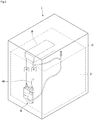
- FIG. 1 is a view schematically showing the inside of a cooking chamber of a cooking appliance according to an embodiment of the present invention
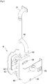
- FIG. 2 is a view showing a state in which a steam generator and a water tank are installed in a cooking appliance according to an embodiment of the present invention
- FIG. 3 is an exploded perspective view of a steam generator according to an embodiment of the present invention
- FIG. 4 is a view showing arrangement of a water tank, a steam generator, a connector and a check valve according to an embodiment of the present invention.
- the cooking appliance 1 may include a main body 10.
- the main body 10 may include a cooking chamber 12.
- the cooking appliance 1 may further include a door connected to the main body 10 to open or close the cooking chamber 12.
- the cooking appliance 1 may include a plurality of heating sources in order to cook the food contained in the cooking chamber 12.
- the plurality of heating sources may include different types of heating sources.
- the plurality of heating sources may include, for example, a heater 21.
- the heater 21 may be located above the cooking chamber 12 and may supply heat to the upper side of the cooking chamber 12.
- the upper heater 21 may be located above the cooking chamber 12 at the outside of the cooking chamber 12. In this case, an opening, through which heat passes, may be formed in the upper wall of the cooking chamber 12.
- a transmission part may be provided in the upper wall of the cooking chamber 12.
- an additional heater may be further provided at the lower side of the cooking chamber 12.
- the plurality of heating sources may further include a convection heater (not shown) configuring a convection device 24.
- the convection device 24 may include a convection fan. By the convection fan, air in the cooking chamber 21 may flow to the convection heater, thereby being heated and then the heated air is supplied to the cooking chamber 12.
- the plurality of heating sources further includes a steam generator 40 for heating water to generate steam.
- the cooking appliance 1 further includes a water tank 30 for supplying water to the steam generator 40.
- the water tank 30 is disposed at a position higher than the steam generator 40 in the main body 10.
- the water tank 30 may be located above the cooking chamber 12.
- the water tank 30 may be installed on or close to the rear wall of the cooking chamber 12 but above the cooking chamber 12.
- the steam generator 40 may be installed on the rear wall of the cooking chamber 12.
- the cooking appliance 1 further includes a water supply pipe 31 and 35 for supplying the water of the water tank 30 to the steam generator 40. Furthermore, the cooking appliance 1 further includes a water supply pump P1 connected to the water supply pipe 31. Moreover, a drain pipe 36 is provided for discharging the water of the steam generator 40. The water is preferably discharged by use of a drainage pump P2 connected to the drain pipe 36.
- the drain pipe 36 may be connected to the water tank 30. Accordingly, the water of the water tank 30 may be supplied to the steam generator 40, and the water of the steam generator 40 may be drained and returned to the water tank 30.
- the steam generator 40 may include a first body 410 and a second body 420 coupled to the first body 410.
- the first body 410 and the second body 420 may form a heating chamber 411.
- a steam heater 430 may be embedded in any one of the first body 410 and the second body 420.
- the steam heater 430 is installed in the first body 410.
- Water supplied from the water tank 30 may be heated by heat generated by the steam heater 430 in the heating chamber 411.
- a water supply part 412 for supplying water to the heating chamber 411 may be provided in any one of the first body 410 and the second body 420.
- the water supply part 412 may communicate with the water supply pipes 31 and 35.
- the water supply part 412 may be provided in the first body 410, for example.
- a steam discharge part 418 for discharging steam generated by the heating chamber 411 may be provided in any one of the first body 410 and the second body 420.
- the steam discharge part 418 is provided in the first body 410, for example.
- a drain part 424 for discharging water of the heating chamber 411 may be provided in any one of the first body 410 and the second body 420.
- the drain part 424 is provided in the second body 420.
- the drain pipe 36 may be connected to the drain part 424.
- the water supply part 412 may be located at a position higher than the drain part 424 and located at a position lower than the steam discharge part 418.
- the position higher or lower relates to a steam generator being assembled and fixed in or at the cooking appliance.
- the steam generator 40 may further include a mounting bracket 470 for mounting the steam generator 40 in the main body 10.
- the mounting bracket 470 may be, for example, coupled to the first body 410.
- the mounting bracket 470 may include a steam guide pipe 472 for guiding the steam discharged from the steam discharge part 418. So the steam guide pipe 472 of the mounting bracket 470 communicates with the steam discharge part 418 of the steam generator 40.
- the cooking appliance 1 may further include a steam supply pipe 440 connected to the steam discharge part 418 preferably, via the steam guide pipe 472, to supply the steam generated by the steam generator 40 to the cooking chamber 12.
- the steam supply pipe 440 may be connected to a steam supply port 14.
- the steam supply port 14 is, for example, coupled to the main body 10 to finally supply steam to the cooking chamber 12.
- the steam supply port 14 may be exposed to the cooking chamber 12.
- the steam supply pipe 440 may be directly connected to the main body 10 and the end of the steam supply pipe 440 may include the steam supply port 14.
- the steam supply pipe 440 is bent once or more to guide the steam discharged from the steam discharge part 418 upward and to supply the steam to the cooking chamber 12.
- the water supply pipe 31 and 35 include the first water supply pipe 31 connected to the water tank 30 and the second water supply pipe 35 connected to the steam generator 40.
- the whole of the second water supply pipe 35 is located at a position higher than the water supply part 412.
- the water supply pump P1 may be, for example, provided on the first water supply pipe 31.
- a connector 32 is connected to the first water supply pipe 31.
- the connector 32 may be a T-shaped connector, for example.
- the first water supply pipe 31 and the second water supply pipe 35 are connected to the connector 32.
- a branch pipe 33 is connected to the connector 32.
- a check valve 34 is connected to an end of the branch pipe 33.
- the check valve 34 communicates with outside air (air located outside the cooking chamber 12, because the check valve 34 is located inside the cooking appliance 1) such that the pressure of the branch pipe 33 is maintained at atmospheric pressure.
- the check valve 34 prevents water flowing to the branch pipe 33 from being discharged to the outside.
- the check valve 34 may include a housing having an opening communicating with the outside, a moving body moved in the housing, and an elastic member supporting the moving body.
- the moving body may be maintained in a state of being separated from the opening by the elastic force of the elastic member.
- water pressurizes the moving body such that the moving body blocks the opening. Accordingly, even when water is moved to the branch pipe 33, it is possible to prevent water from being leaked by the check valve 34.
- the connector 32, the branch pipe 33 and the check valve 34 are located at a position higher than the water tank 30 from the bottom to prevent water from flowing to the branch pipe 33.
- a portion of the first water supply pipe 31 may be located at a position higher than the water tank 30.
- a portion of the second water supply pipe 35 may be located at a position higher than the water tank 30.
- the pressure of the branch pipe 33 is atmospheric pressure and the pressures of the water supply pipes 31 and 35 become less than the atmospheric pressure at the time of operating the water supply pump P1, water does not flow to the branch pipe 33.
- the water of the water tank 30 may be smoothly supplied to the steam generator 40 through the first water supply pipe 31 and the second water supply pipe 35.
- the water tank 30 is located at a position higher than the steam generator 40, even after operation of the water supply pump P1 is completed, negative pressure is generated in the water tank 30 and thus some of the water of the water tank 30 may be discharged to the first water supply pipe 31.
- the pressure of the branch pipe 33 is atmospheric pressure, the water discharged to the first water supply pipe 31 flows to the branch pipe 33 and remains in the branch pipe 33. As described above, the water flowing to the branch pipe 33 is prevented from being discharged by the check valve 34.
- FIG. 5 is a view showing arrangement of a water tank, a steam generator, a connector and a check valve according to another embodiment of the present invention.
- the present embodiment is equal to the previous embodiment except for arrangement in the second water supply pipe connected to the steam generator. Therefore, hereinafter, the characteristics of the present embodiment will be described.
- a first water supply pipe 31, a second water supply pipe 35a and a branch pipe 33 are connected to a connector 32.
- the second water supply pipe 35a is connected to a water supply part 412 of a steam generator 40. At this time, in a state in which the second water supply pipe 35a is connected to the water supply part 412, a portion of the second water supply pipe 35a may be located at a position lower than the water supply part 412.
- the length L2 of the branch pipe 33 is greater than the length L1 of a portion 35b, which is located at a position lower than the water supply part 412, of the second water supply pipe 35a.
- the second water supply pipe 35a is filled with water.
- the steam generator 40 is filled with water in a state in which operation of the water supply pump P1 is stopped, since the water pressure of the steam generator 40 is higher than that of the second water supply pipe 35a located at the position lower than the water supply part 412, the water of the steam generator 40 may be discharged to at least the portion 35b of the second water supply pipe 35a.
- the branch pipe 33 Even if the water of the steam generator 40 is discharged to the second water supply pipe 35a, the water of the second water supply pipe 35a may flow to the branch pipe 33. At this time, if the length L2 of the branch pipe 33 is greater than the length L1 of the portion 35b of the second water supply pipe 35a being lower than the water supply part 412, even when the water of the portion 35b of the second water supply pipe 35a flows to the branch pipe 33, the branch pipe 33 may communicate with outside air and thus the pressure of the branch pipe becomes atmospheric pressure.
Landscapes
- Engineering & Computer Science (AREA)
- Mechanical Engineering (AREA)
- General Engineering & Computer Science (AREA)
- Physics & Mathematics (AREA)
- Thermal Sciences (AREA)
- Food Science & Technology (AREA)
- Combustion & Propulsion (AREA)
- Chemical & Material Sciences (AREA)
- Sustainable Energy (AREA)
- Water Supply & Treatment (AREA)
- Life Sciences & Earth Sciences (AREA)
- Sustainable Development (AREA)
- Cookers (AREA)
- Electric Ovens (AREA)
Description
- The present specification relates to a cooking appliance.
- The cooking appliance refers to an appliance for cooking food using heat of a heating source. The cooking appliance may include a heating source for heating food contained in a cooking chamber.
- In general, the cooking appliance may include at least one or a plurality of heating sources. The one or more heating sources may include an electric heater, a magnetron, a steam generator, etc.
- Korean Patent Registration Publication No.
10-0624080
WO 2005/015088 A1 relates to a cooking device capable of continuously feeding steam to a heating chamber over an extended time period despite its low electric power consumption and a small structure, and a method of driving the cooking device.
US 2016/061490 A1 relates to a cooking appliance having an improved structure in which superheated steam is capable of being used during a cooking operation. The cooking appliance comprises a water tank and a pump are disposed between the main body and the cover and the steam generator is disposed at an outer edge of the rear frame of the main body below the water tank and the water pump. - Further relevant prior art can be found in
EP2462808 A1 . - If a water supply pump is used as the water supply control valve, the water of the water tank is supplied to the steam generator when the water supply pump operates, and the water supply pump is stopped when water supply is completed. However, since the water tank is located at the upper side of the steam generator, even when operation of the water supply pump is stopped, negative pressure may be generated, thereby supplying the water of the water tank to the steam generator.
- If the amount of water supplied to the steam generator is large after an operation of the water supply pump is stopped, water may overflow from the steam generator.
- The above identified objectives are solved by the features of the independent claim. Advantageous embodiments are derived from the respective dependent claims.
- The present embodiment provides a cooking appliance capable of preventing water from being additionally supplied to a steam generator due to negative pressure, in particular in a state in which a water supply pump is stopped after water is supplied to the steam generator.
- The present embodiment provides a cooking appliance capable of preventing water discharged from a water tank from being leaked after a water supply pump is stopped.
- The object is solved by the features of the independent claims. Preferred embodiments are given in the dependent claims.
- According to an aspect, a cooking appliance includes a main body including a cooking chamber, a steam generator including a steam heater for generating steam for heating food contained in the cooking chamber, a water tank configured to store water to be supplied to the steam generator, a water supply pump configured to operate in order to supply water of the water tank to the steam generator, a first water supply pipe connected to the water tank, a connector connected to the first water supply pipe, a second water supply pipe connected to the connector and connected to the steam generator, and a branch pipe connected to the connector. The water tank is located at a position higher than the steam generator, and the connector and the branch pipe are located at positions higher than the water tank.
- The connector may be formed in a T shape.
- A portion of the first water supply pipe may be located at a position higher than the water tank.
- A portion of the second water supply pipe may be located at a position higher than the water tank.
- A check valve capable of preventing water from being leaked and communicating with outside air is connected to the branch pipe.
- The check valve may be located at a position higher than the water tank.
- The steam generator may include a water supply part, into which water supplied from the second water supply pipe flows. The whole of the second water supply pipe may be located at a position higher than the water supply part.
- The steam generator may include a water supply part, into which water supplied from the second water supply pipe flows.
- A portion of the second water supply pipe may be located at a position lower than the water supply part.
- A length of the branch pipe may be greater than a length of the portion of the second water supply pipe located at the position lower than the water supply part.
- The water tank may be located at an upper side of the cooking chamber, and the steam generator is located at a rear side of the cooking chamber.
- The cooking appliance may further comprise: a drain pipe configured to connect the steam generator and the water tank; and a drainage pump provided on the drain pipe.
-
-
FIG. 1 is a view schematically showing the inside of a cooking chamber of a cooking appliance according to an embodiment of the present invention. -
FIG. 2 is a view showing a state in which a steam generator and a water tank are installed in a cooking appliance according to an embodiment of the present invention. -
FIG. 3 is an exploded perspective view of a steam generator according to an embodiment of the present invention. -
FIG. 4 is a view showing arrangement of a water tank, a steam generator, a connector and a check valve according to an embodiment of the present invention. -
FIG. 5 is a view showing arrangement of a water tank, a steam generator, a connector and a check valve according to another embodiment of the present invention. - Hereinafter, some embodiments of the present disclosure will be described in detail with reference to the accompanying drawings. It should be noted that when components in the drawings are designated by reference numerals, the same components have the same reference numerals as far as possible even though the components are illustrated in different drawings. Further, in description of embodiments of the present disclosure, when it is determined that detailed descriptions of well-known configurations or functions disturb understanding of the embodiments of the present disclosure, the detailed descriptions will be omitted.
- Also, in the description of the embodiments of the present disclosure, the terms such as first, second, A, B, (a) and (b) may be used. Each of the terms is merely used to distinguish the corresponding component from other components, and does not delimit an essence, an order or a sequence of the corresponding component. It should be understood that when one component is "connected", "coupled" or "joined" to another component, the former may be directly connected or jointed to the latter or may be "connected", coupled" or "joined" to the latter with a third component interposed therebetween.
-
FIG. 1 is a view schematically showing the inside of a cooking chamber of a cooking appliance according to an embodiment of the present invention,FIG. 2 is a view showing a state in which a steam generator and a water tank are installed in a cooking appliance according to an embodiment of the present invention,FIG. 3 is an exploded perspective view of a steam generator according to an embodiment of the present invention, andFIG. 4 is a view showing arrangement of a water tank, a steam generator, a connector and a check valve according to an embodiment of the present invention. - Referring to
FIGS. 1 to 4 , thecooking appliance 1 according to the embodiment of the present invention may include amain body 10. Themain body 10 may include acooking chamber 12. Although not shown, thecooking appliance 1 may further include a door connected to themain body 10 to open or close thecooking chamber 12. - The
cooking appliance 1 may include a plurality of heating sources in order to cook the food contained in thecooking chamber 12. - The plurality of heating sources may include different types of heating sources.
- Although not limited, the plurality of heating sources may include, for example, a
heater 21. - The
heater 21 may be located above thecooking chamber 12 and may supply heat to the upper side of thecooking chamber 12. Of course, theupper heater 21 may be located above thecooking chamber 12 at the outside of thecooking chamber 12. In this case, an opening, through which heat passes, may be formed in the upper wall of thecooking chamber 12. Alternatively, when the upper heater generates radiant energy, a transmission part may be provided in the upper wall of thecooking chamber 12. - Alternatively, an additional heater may be further provided at the lower side of the
cooking chamber 12. - Alternatively, the plurality of heating sources may further include a convection heater (not shown) configuring a
convection device 24. Theconvection device 24 may include a convection fan. By the convection fan, air in thecooking chamber 21 may flow to the convection heater, thereby being heated and then the heated air is supplied to thecooking chamber 12. - The plurality of heating sources further includes a
steam generator 40 for heating water to generate steam. - The
cooking appliance 1 further includes awater tank 30 for supplying water to thesteam generator 40. Thewater tank 30 is disposed at a position higher than thesteam generator 40 in themain body 10. - For example, the
water tank 30 may be located above thecooking chamber 12. Thewater tank 30 may be installed on or close to the rear wall of thecooking chamber 12 but above thecooking chamber 12. Thesteam generator 40 may be installed on the rear wall of thecooking chamber 12. - The
cooking appliance 1 further includes awater supply pipe water tank 30 to thesteam generator 40. Furthermore, thecooking appliance 1 further includes a water supply pump P1 connected to thewater supply pipe 31. Moreover, adrain pipe 36 is provided for discharging the water of thesteam generator 40. The water is preferably discharged by use of a drainage pump P2 connected to thedrain pipe 36. - Although not limited, the
drain pipe 36 may be connected to thewater tank 30. Accordingly, the water of thewater tank 30 may be supplied to thesteam generator 40, and the water of thesteam generator 40 may be drained and returned to thewater tank 30. - The
steam generator 40 may include afirst body 410 and asecond body 420 coupled to thefirst body 410. - In a state in which the
first body 410 and thesecond body 420 are coupled, thefirst body 410 and thesecond body 420 may form a heating chamber 411. - A
steam heater 430 may be embedded in any one of thefirst body 410 and thesecond body 420. - In
FIG. 3 , for example, thesteam heater 430 is installed in thefirst body 410. - Water supplied from the
water tank 30 may be heated by heat generated by thesteam heater 430 in the heating chamber 411. - A
water supply part 412 for supplying water to the heating chamber 411 may be provided in any one of thefirst body 410 and thesecond body 420. Thewater supply part 412 may communicate with thewater supply pipes - In the present embodiment, the
water supply part 412 may be provided in thefirst body 410, for example. - A
steam discharge part 418 for discharging steam generated by the heating chamber 411 may be provided in any one of thefirst body 410 and thesecond body 420. - In
FIG. 3 , thesteam discharge part 418 is provided in thefirst body 410, for example. - A
drain part 424 for discharging water of the heating chamber 411 may be provided in any one of thefirst body 410 and thesecond body 420. - In
FIG. 3 , for example, thedrain part 424 is provided in thesecond body 420. Thedrain pipe 36 may be connected to thedrain part 424. - The
water supply part 412 may be located at a position higher than thedrain part 424 and located at a position lower than thesteam discharge part 418. The position higher or lower relates to a steam generator being assembled and fixed in or at the cooking appliance. - The
steam generator 40 may further include a mountingbracket 470 for mounting thesteam generator 40 in themain body 10. The mountingbracket 470 may be, for example, coupled to thefirst body 410. - The mounting
bracket 470 may include asteam guide pipe 472 for guiding the steam discharged from thesteam discharge part 418. So thesteam guide pipe 472 of the mountingbracket 470 communicates with thesteam discharge part 418 of thesteam generator 40. - The
cooking appliance 1 may further include asteam supply pipe 440 connected to thesteam discharge part 418 preferably, via thesteam guide pipe 472, to supply the steam generated by thesteam generator 40 to thecooking chamber 12. - The
steam supply pipe 440 may be connected to asteam supply port 14. Thesteam supply port 14 is, for example, coupled to themain body 10 to finally supply steam to thecooking chamber 12. - Accordingly, at least a portion of the
steam supply port 14 may be exposed to thecooking chamber 12. - As another example, the
steam supply pipe 440 may be directly connected to themain body 10 and the end of thesteam supply pipe 440 may include thesteam supply port 14. - The
steam supply pipe 440 is bent once or more to guide the steam discharged from thesteam discharge part 418 upward and to supply the steam to thecooking chamber 12. - Meanwhile, the
water supply pipe water supply pipe 31 connected to thewater tank 30 and the secondwater supply pipe 35 connected to thesteam generator 40. - Although not limited, in a state in which the second
water supply pipe 35 is connected to thewater supply part 412, the whole of the secondwater supply pipe 35 is located at a position higher than thewater supply part 412. - The water supply pump P1 may be, for example, provided on the first
water supply pipe 31. Aconnector 32 is connected to the firstwater supply pipe 31. Theconnector 32 may be a T-shaped connector, for example. - Accordingly, the first
water supply pipe 31 and the secondwater supply pipe 35 are connected to theconnector 32. - In addition, a branch pipe 33 is connected to the
connector 32. In addition, acheck valve 34 is connected to an end of the branch pipe 33. Thecheck valve 34 communicates with outside air (air located outside thecooking chamber 12, because thecheck valve 34 is located inside the cooking appliance 1) such that the pressure of the branch pipe 33 is maintained at atmospheric pressure. - The
check valve 34 prevents water flowing to the branch pipe 33 from being discharged to the outside. For example, thecheck valve 34 may include a housing having an opening communicating with the outside, a moving body moved in the housing, and an elastic member supporting the moving body. - The moving body may be maintained in a state of being separated from the opening by the elastic force of the elastic member. In contrast, when water flows to the branch pipe, water pressurizes the moving body such that the moving body blocks the opening. Accordingly, even when water is moved to the branch pipe 33, it is possible to prevent water from being leaked by the
check valve 34. - Before the water supply pump P1 operates or when the water supply pump P1 operates, the
connector 32, the branch pipe 33 and thecheck valve 34 are located at a position higher than thewater tank 30 from the bottom to prevent water from flowing to the branch pipe 33. - In addition, a portion of the first
water supply pipe 31 may be located at a position higher than thewater tank 30. In addition, a portion of the secondwater supply pipe 35 may be located at a position higher than thewater tank 30. - Accordingly, since the pressure of the branch pipe 33 is atmospheric pressure and the pressures of the
water supply pipes - At the time of operating the water supply pump P1, the water of the
water tank 30 may be smoothly supplied to thesteam generator 40 through the firstwater supply pipe 31 and the secondwater supply pipe 35. - Meanwhile, since the
water tank 30 is located at a position higher than thesteam generator 40, even after operation of the water supply pump P1 is completed, negative pressure is generated in thewater tank 30 and thus some of the water of thewater tank 30 may be discharged to the firstwater supply pipe 31. - In the present embodiment, since the pressure of the branch pipe 33 is atmospheric pressure, the water discharged to the first
water supply pipe 31 flows to the branch pipe 33 and remains in the branch pipe 33. As described above, the water flowing to the branch pipe 33 is prevented from being discharged by thecheck valve 34. - According to the present embodiment, even when water is discharged from the
water tank 30 by the negative pressure of thewater tank 30 after operation of the water supply pump P1 is completed, since the water discharged from thewater tank 30 flows to the branch pipe 33, water is prevented from being supplied to thesteam generator 40. - When the water discharged from the
water tank 30 is not supplied to thesteam generator 40, it is possible to prevent a phenomenon that water overflows from thesteam generator 40 and flows into thecooking chamber 12. -
FIG. 5 is a view showing arrangement of a water tank, a steam generator, a connector and a check valve according to another embodiment of the present invention. - The present embodiment is equal to the previous embodiment except for arrangement in the second water supply pipe connected to the steam generator. Therefore, hereinafter, the characteristics of the present embodiment will be described.
- Referring to
FIG. 5 , a firstwater supply pipe 31, a secondwater supply pipe 35a and a branch pipe 33 are connected to aconnector 32. - The second
water supply pipe 35a is connected to awater supply part 412 of asteam generator 40. At this time, in a state in which the secondwater supply pipe 35a is connected to thewater supply part 412, a portion of the secondwater supply pipe 35a may be located at a position lower than thewater supply part 412. - In the present embodiment, the length L2 of the branch pipe 33 is greater than the length L1 of a
portion 35b, which is located at a position lower than thewater supply part 412, of the secondwater supply pipe 35a. - In a state in which operation of the water supply pump P1 is stopped, the second
water supply pipe 35a is filled with water. - If the
steam generator 40 is filled with water in a state in which operation of the water supply pump P1 is stopped, since the water pressure of thesteam generator 40 is higher than that of the secondwater supply pipe 35a located at the position lower than thewater supply part 412, the water of thesteam generator 40 may be discharged to at least theportion 35b of the secondwater supply pipe 35a. - Even if the water of the
steam generator 40 is discharged to the secondwater supply pipe 35a, the water of the secondwater supply pipe 35a may flow to the branch pipe 33. At this time, if the length L2 of the branch pipe 33 is greater than the length L1 of theportion 35b of the secondwater supply pipe 35a being lower than thewater supply part 412, even when the water of theportion 35b of the secondwater supply pipe 35a flows to the branch pipe 33, the branch pipe 33 may communicate with outside air and thus the pressure of the branch pipe becomes atmospheric pressure. - In this case, when the water supply pump P1 operates later, the water of the branch pipe 33 flows to the second
water supply pipe 35a again.
Claims (10)
- A cooking appliance comprising:a main body (10) including a cooking chamber (12);a steam generator (40) for generating steam for being supplied to the cooking chamber (12);a water tank (30) configured to store water to be supplied to the steam generator (40);a water supply pump (P1) configured to operate in order to supply water of the water tank (30) to the steam generator (40);a first water supply pipe (31) connected to the water tank (30);a connector (32) connected to the first water supply pipe (31); anda second water supply pipe (35) connected to the connector (32) and connected to the steam generator (40);a branch pipe (33) connected to the connector (32); andwherein the water tank (30) is located at a position higher than the steam generator (40),characterized in that the cooking appliance further comprises:a check valve (34) connected to the branch pipe (33), the check valve (34) being capable of preventing water from being leaked and communicating with outside air, andwherein the connector (32) and the branch pipe (33) are located at positions higher than the water tank (30).
- The cooking appliance of claim 1, wherein the connector (32) is formed in a T shape.
- The cooking appliance of claim 1 or 2, wherein a portion of the first water supply pipe (31) is located at a position higher than the water tank (30).
- The cooking appliance of any one of claims 1 to 3, wherein a portion of the second water supply pipe (35) is located at a position higher than the water tank (30).
- The cooking appliance of claim 1, wherein the check valve (34) is located at a position higher than the water tank (30).
- The cooking appliance of any one of claims 1 to 5, wherein the steam generator (40) includes a water supply part (412), into which water supplied from the second water supply pipe (35) flows, and
wherein the second water supply pipe (35) is located at a position higher than the water supply part (412). - The cooking appliance of any one of claims 1 to 5, wherein the steam generator (40) includes a water supply part (412), into which water supplied from the second water supply pipe (35) flows,
wherein a portion of the second water supply pipe (35a) is located at a position lower than the water supply part (412). - The cooking appliance of claim 7, wherein a length (L2) of the branch pipe (33) is greater than a length (L1) of the portion of the second water supply pipe (35a) located at the position lower than the water supply part (412).
- The cooking appliance of any one of claims 1 to 8, wherein the water tank (30) is located at an upper side of the cooking chamber (12), and
wherein the steam generator (40) is located at a rear side of the cooking chamber (12). - The cooking appliance of any one of claims 1 to 9, further comprising:a drain pipe (36) configured to connect the steam generator (40) and the water tank (30);
anda drainage pump (P2) provided on the drain pipe (36).
Applications Claiming Priority (1)
| Application Number | Priority Date | Filing Date | Title |
|---|---|---|---|
| KR1020180042659A KR102110413B1 (en) | 2018-04-12 | 2018-04-12 | Cooking appiance |
Publications (2)
| Publication Number | Publication Date |
|---|---|
| EP3553393A1 EP3553393A1 (en) | 2019-10-16 |
| EP3553393B1 true EP3553393B1 (en) | 2020-11-04 |
Family
ID=64572136
Family Applications (1)
| Application Number | Title | Priority Date | Filing Date |
|---|---|---|---|
| EP18209696.6A Active EP3553393B1 (en) | 2018-04-12 | 2018-12-03 | Cooking appliance |
Country Status (3)
| Country | Link |
|---|---|
| US (1) | US10874245B2 (en) |
| EP (1) | EP3553393B1 (en) |
| KR (1) | KR102110413B1 (en) |
Families Citing this family (8)
| Publication number | Priority date | Publication date | Assignee | Title |
|---|---|---|---|---|
| CN110200516A (en) | 2017-08-09 | 2019-09-06 | 沙克忍者运营有限责任公司 | Cooking system |
| WO2020176477A1 (en) | 2019-02-25 | 2020-09-03 | Sharkninja Operating Llc | Cooking system with guard |
| US11033146B2 (en) | 2019-02-25 | 2021-06-15 | Sharkninja Operating Llc | Cooking device and components thereof |
| US11647861B2 (en) | 2020-03-30 | 2023-05-16 | Sharkninja Operating Llc | Cooking device and components thereof |
| CN113842030B (en) * | 2020-12-30 | 2022-08-09 | 九阳股份有限公司 | Cooking utensil |
| CN112806839B (en) * | 2021-02-07 | 2021-11-09 | 珠海格力电器股份有限公司 | Steam generator control method and device, steam generator and steam oven |
| DE102021202846A1 (en) * | 2021-03-23 | 2022-09-29 | BSH Hausgeräte GmbH | Steam cooker with a specific fluid line system and method |
| WO2026024248A1 (en) * | 2024-07-24 | 2026-01-29 | Renta Elektrikli Ev Aletleri Sanayi Ve Dis Ticaret Limited Sirketi | Apparatus for safely discharging leakage water from an outer surface of a water transfer hose in steam ovens |
Citations (2)
| Publication number | Priority date | Publication date | Assignee | Title |
|---|---|---|---|---|
| DE102006062069A1 (en) * | 2006-12-29 | 2008-07-03 | BSH Bosch und Siemens Hausgeräte GmbH | Cooking appliance steam generating device with at least one instantaneous water heater |
| KR101480462B1 (en) * | 2008-07-21 | 2015-01-12 | 엘지전자 주식회사 | Steam oven |
Family Cites Families (13)
| Publication number | Priority date | Publication date | Assignee | Title |
|---|---|---|---|---|
| US2569757A (en) * | 1947-03-28 | 1951-10-02 | Gubson Philip | Heating apparatus |
| US4320702A (en) * | 1980-03-20 | 1982-03-23 | Refreshment Machinery Incorporated | Steam generator |
| EP1423013A2 (en) * | 2001-09-07 | 2004-06-02 | Alto-Shaam, Inc. | Humidity control system for combination oven |
| JP2004138346A (en) * | 2002-10-18 | 2004-05-13 | Matsushita Electric Ind Co Ltd | Superheated steam cooking device |
| JP2005061669A (en) * | 2003-08-08 | 2005-03-10 | Matsushita Electric Ind Co Ltd | Heating device and driving method thereof |
| KR100624080B1 (en) | 2003-12-09 | 2006-09-19 | 삼성전자주식회사 | Heating cooker |
| JP4190425B2 (en) * | 2004-01-07 | 2008-12-03 | シャープ株式会社 | Steam cooker |
| US7537004B2 (en) * | 2005-05-03 | 2009-05-26 | Whirlpool Corporation | Steam oven with fluid supply and drain vessel |
| JP4435246B2 (en) * | 2008-06-26 | 2010-03-17 | シャープ株式会社 | Steam generator and cooking device |
| KR101593228B1 (en) * | 2009-04-10 | 2016-02-11 | 엘지전자 주식회사 | Cooking equipment |
| EP2462808B1 (en) * | 2010-12-13 | 2019-11-13 | BSH Hausgeräte GmbH | Steam oven |
| KR102226003B1 (en) * | 2014-09-02 | 2021-03-10 | 삼성전자주식회사 | Cooking appliance |
| KR101582513B1 (en) * | 2015-01-15 | 2016-01-05 | 유도썬스(주) | Boiler vacuum releasing apparatus for protection of water supply pump |
-
2018
- 2018-04-12 KR KR1020180042659A patent/KR102110413B1/en active Active
- 2018-12-03 EP EP18209696.6A patent/EP3553393B1/en active Active
-
2019
- 2019-03-05 US US16/292,866 patent/US10874245B2/en active Active
Patent Citations (2)
| Publication number | Priority date | Publication date | Assignee | Title |
|---|---|---|---|---|
| DE102006062069A1 (en) * | 2006-12-29 | 2008-07-03 | BSH Bosch und Siemens Hausgeräte GmbH | Cooking appliance steam generating device with at least one instantaneous water heater |
| KR101480462B1 (en) * | 2008-07-21 | 2015-01-12 | 엘지전자 주식회사 | Steam oven |
Also Published As
| Publication number | Publication date |
|---|---|
| US20190313832A1 (en) | 2019-10-17 |
| US10874245B2 (en) | 2020-12-29 |
| KR20190119337A (en) | 2019-10-22 |
| EP3553393A1 (en) | 2019-10-16 |
| KR102110413B1 (en) | 2020-05-14 |
Similar Documents
| Publication | Publication Date | Title |
|---|---|---|
| EP3553393A1 (en) | Cooking appliance | |
| CN101152049B (en) | Steam generator and heating cooking apparatus having the same | |
| KR101860714B1 (en) | Steam cooking apparatus | |
| KR102422877B1 (en) | Control method of cooking apparatus | |
| KR102596949B1 (en) | Steam cooker | |
| EP2775217B1 (en) | Steam cooking appliance | |
| US10871291B2 (en) | Cooking appliance | |
| EP1654931B1 (en) | Steam generator for steam oven | |
| EP3575685B1 (en) | Steam generator and cooking apparatus including same | |
| KR102813797B1 (en) | Cooking appliance | |
| JP4049787B2 (en) | Superheated steam cooker | |
| EP2775216B1 (en) | Steam cooking appliance | |
| EP3561393B1 (en) | Cooking appliance | |
| EP1550828A1 (en) | Heating cooker having a steam generating unit | |
| CN100367860C (en) | heating cooker | |
| EP3667174A1 (en) | Cooking appliance and control method for controlling the same | |
| CN102551556B (en) | Boiling vessel | |
| KR102067828B1 (en) | A steam oven range | |
| KR102022637B1 (en) | A steam oven range | |
| KR100820735B1 (en) | Superheated Steam Cooker | |
| KR100610669B1 (en) | Heating cooker | |
| JP2006162234A (en) | Cooking device with steam generation function | |
| KR102555384B1 (en) | Cooking device | |
| KR20190117246A (en) | Cooking appliance | |
| KR102490845B1 (en) | Steam generating apparatus and cooking device having the same |
Legal Events
| Date | Code | Title | Description |
|---|---|---|---|
| PUAI | Public reference made under article 153(3) epc to a published international application that has entered the european phase |
Free format text: ORIGINAL CODE: 0009012 |
|
| STAA | Information on the status of an ep patent application or granted ep patent |
Free format text: STATUS: REQUEST FOR EXAMINATION WAS MADE |
|
| 17P | Request for examination filed |
Effective date: 20181203 |
|
| AK | Designated contracting states |
Kind code of ref document: A1 Designated state(s): AL AT BE BG CH CY CZ DE DK EE ES FI FR GB GR HR HU IE IS IT LI LT LU LV MC MK MT NL NO PL PT RO RS SE SI SK SM TR |
|
| AX | Request for extension of the european patent |
Extension state: BA ME |
|
| RBV | Designated contracting states (corrected) |
Designated state(s): AL AT BE BG CH CY CZ DE DK EE ES FI FR GB GR HR HU IE IS IT LI LT LU LV MC MK MT NL NO PL PT RO RS SE SI SK SM TR |
|
| REG | Reference to a national code |
Ref country code: DE Ref legal event code: R079 Ref document number: 602018009417 Country of ref document: DE Free format text: PREVIOUS MAIN CLASS: F24C0015320000 Ipc: F24C0015000000 |
|
| GRAP | Despatch of communication of intention to grant a patent |
Free format text: ORIGINAL CODE: EPIDOSNIGR1 |
|
| STAA | Information on the status of an ep patent application or granted ep patent |
Free format text: STATUS: GRANT OF PATENT IS INTENDED |
|
| RIC1 | Information provided on ipc code assigned before grant |
Ipc: A21B 3/04 20060101ALI20200515BHEP Ipc: F24C 15/00 20060101AFI20200515BHEP Ipc: F24C 15/32 20060101ALI20200515BHEP |
|
| INTG | Intention to grant announced |
Effective date: 20200608 |
|
| GRAS | Grant fee paid |
Free format text: ORIGINAL CODE: EPIDOSNIGR3 |
|
| GRAA | (expected) grant |
Free format text: ORIGINAL CODE: 0009210 |
|
| STAA | Information on the status of an ep patent application or granted ep patent |
Free format text: STATUS: THE PATENT HAS BEEN GRANTED |
|
| AK | Designated contracting states |
Kind code of ref document: B1 Designated state(s): AL AT BE BG CH CY CZ DE DK EE ES FI FR GB GR HR HU IE IS IT LI LT LU LV MC MK MT NL NO PL PT RO RS SE SI SK SM TR |
|
| REG | Reference to a national code |
Ref country code: GB Ref legal event code: FG4D |
|
| REG | Reference to a national code |
Ref country code: CH Ref legal event code: EP |
|
| REG | Reference to a national code |
Ref country code: AT Ref legal event code: REF Ref document number: 1331327 Country of ref document: AT Kind code of ref document: T Effective date: 20201115 |
|
| REG | Reference to a national code |
Ref country code: IE Ref legal event code: FG4D |
|
| REG | Reference to a national code |
Ref country code: DE Ref legal event code: R096 Ref document number: 602018009417 Country of ref document: DE |
|
| REG | Reference to a national code |
Ref country code: NL Ref legal event code: MP Effective date: 20201104 |
|
| REG | Reference to a national code |
Ref country code: AT Ref legal event code: MK05 Ref document number: 1331327 Country of ref document: AT Kind code of ref document: T Effective date: 20201104 |
|
| PG25 | Lapsed in a contracting state [announced via postgrant information from national office to epo] |
Ref country code: GR Free format text: LAPSE BECAUSE OF FAILURE TO SUBMIT A TRANSLATION OF THE DESCRIPTION OR TO PAY THE FEE WITHIN THE PRESCRIBED TIME-LIMIT Effective date: 20210205 Ref country code: NO Free format text: LAPSE BECAUSE OF FAILURE TO SUBMIT A TRANSLATION OF THE DESCRIPTION OR TO PAY THE FEE WITHIN THE PRESCRIBED TIME-LIMIT Effective date: 20210204 Ref country code: FI Free format text: LAPSE BECAUSE OF FAILURE TO SUBMIT A TRANSLATION OF THE DESCRIPTION OR TO PAY THE FEE WITHIN THE PRESCRIBED TIME-LIMIT Effective date: 20201104 Ref country code: RS Free format text: LAPSE BECAUSE OF FAILURE TO SUBMIT A TRANSLATION OF THE DESCRIPTION OR TO PAY THE FEE WITHIN THE PRESCRIBED TIME-LIMIT Effective date: 20201104 Ref country code: PT Free format text: LAPSE BECAUSE OF FAILURE TO SUBMIT A TRANSLATION OF THE DESCRIPTION OR TO PAY THE FEE WITHIN THE PRESCRIBED TIME-LIMIT Effective date: 20210304 |
|
| PG25 | Lapsed in a contracting state [announced via postgrant information from national office to epo] |
Ref country code: ES Free format text: LAPSE BECAUSE OF FAILURE TO SUBMIT A TRANSLATION OF THE DESCRIPTION OR TO PAY THE FEE WITHIN THE PRESCRIBED TIME-LIMIT Effective date: 20201104 Ref country code: AT Free format text: LAPSE BECAUSE OF FAILURE TO SUBMIT A TRANSLATION OF THE DESCRIPTION OR TO PAY THE FEE WITHIN THE PRESCRIBED TIME-LIMIT Effective date: 20201104 Ref country code: BG Free format text: LAPSE BECAUSE OF FAILURE TO SUBMIT A TRANSLATION OF THE DESCRIPTION OR TO PAY THE FEE WITHIN THE PRESCRIBED TIME-LIMIT Effective date: 20210204 Ref country code: LV Free format text: LAPSE BECAUSE OF FAILURE TO SUBMIT A TRANSLATION OF THE DESCRIPTION OR TO PAY THE FEE WITHIN THE PRESCRIBED TIME-LIMIT Effective date: 20201104 Ref country code: PL Free format text: LAPSE BECAUSE OF FAILURE TO SUBMIT A TRANSLATION OF THE DESCRIPTION OR TO PAY THE FEE WITHIN THE PRESCRIBED TIME-LIMIT Effective date: 20201104 Ref country code: IS Free format text: LAPSE BECAUSE OF FAILURE TO SUBMIT A TRANSLATION OF THE DESCRIPTION OR TO PAY THE FEE WITHIN THE PRESCRIBED TIME-LIMIT Effective date: 20210304 Ref country code: SE Free format text: LAPSE BECAUSE OF FAILURE TO SUBMIT A TRANSLATION OF THE DESCRIPTION OR TO PAY THE FEE WITHIN THE PRESCRIBED TIME-LIMIT Effective date: 20201104 |
|
| REG | Reference to a national code |
Ref country code: LT Ref legal event code: MG9D |
|
| PG25 | Lapsed in a contracting state [announced via postgrant information from national office to epo] |
Ref country code: HR Free format text: LAPSE BECAUSE OF FAILURE TO SUBMIT A TRANSLATION OF THE DESCRIPTION OR TO PAY THE FEE WITHIN THE PRESCRIBED TIME-LIMIT Effective date: 20201104 |
|
| PG25 | Lapsed in a contracting state [announced via postgrant information from national office to epo] |
Ref country code: LT Free format text: LAPSE BECAUSE OF FAILURE TO SUBMIT A TRANSLATION OF THE DESCRIPTION OR TO PAY THE FEE WITHIN THE PRESCRIBED TIME-LIMIT Effective date: 20201104 Ref country code: RO Free format text: LAPSE BECAUSE OF FAILURE TO SUBMIT A TRANSLATION OF THE DESCRIPTION OR TO PAY THE FEE WITHIN THE PRESCRIBED TIME-LIMIT Effective date: 20201104 Ref country code: EE Free format text: LAPSE BECAUSE OF FAILURE TO SUBMIT A TRANSLATION OF THE DESCRIPTION OR TO PAY THE FEE WITHIN THE PRESCRIBED TIME-LIMIT Effective date: 20201104 Ref country code: CZ Free format text: LAPSE BECAUSE OF FAILURE TO SUBMIT A TRANSLATION OF THE DESCRIPTION OR TO PAY THE FEE WITHIN THE PRESCRIBED TIME-LIMIT Effective date: 20201104 Ref country code: SM Free format text: LAPSE BECAUSE OF FAILURE TO SUBMIT A TRANSLATION OF THE DESCRIPTION OR TO PAY THE FEE WITHIN THE PRESCRIBED TIME-LIMIT Effective date: 20201104 Ref country code: SK Free format text: LAPSE BECAUSE OF FAILURE TO SUBMIT A TRANSLATION OF THE DESCRIPTION OR TO PAY THE FEE WITHIN THE PRESCRIBED TIME-LIMIT Effective date: 20201104 |
|
| REG | Reference to a national code |
Ref country code: DE Ref legal event code: R097 Ref document number: 602018009417 Country of ref document: DE |
|
| PG25 | Lapsed in a contracting state [announced via postgrant information from national office to epo] |
Ref country code: DK Free format text: LAPSE BECAUSE OF FAILURE TO SUBMIT A TRANSLATION OF THE DESCRIPTION OR TO PAY THE FEE WITHIN THE PRESCRIBED TIME-LIMIT Effective date: 20201104 Ref country code: MC Free format text: LAPSE BECAUSE OF FAILURE TO SUBMIT A TRANSLATION OF THE DESCRIPTION OR TO PAY THE FEE WITHIN THE PRESCRIBED TIME-LIMIT Effective date: 20201104 |
|
| REG | Reference to a national code |
Ref country code: BE Ref legal event code: MM Effective date: 20201231 |
|
| PLBE | No opposition filed within time limit |
Free format text: ORIGINAL CODE: 0009261 |
|
| STAA | Information on the status of an ep patent application or granted ep patent |
Free format text: STATUS: NO OPPOSITION FILED WITHIN TIME LIMIT |
|
| 26N | No opposition filed |
Effective date: 20210805 |
|
| PG25 | Lapsed in a contracting state [announced via postgrant information from national office to epo] |
Ref country code: LU Free format text: LAPSE BECAUSE OF NON-PAYMENT OF DUE FEES Effective date: 20201203 Ref country code: IE Free format text: LAPSE BECAUSE OF NON-PAYMENT OF DUE FEES Effective date: 20201203 Ref country code: NL Free format text: LAPSE BECAUSE OF FAILURE TO SUBMIT A TRANSLATION OF THE DESCRIPTION OR TO PAY THE FEE WITHIN THE PRESCRIBED TIME-LIMIT Effective date: 20201104 Ref country code: AL Free format text: LAPSE BECAUSE OF FAILURE TO SUBMIT A TRANSLATION OF THE DESCRIPTION OR TO PAY THE FEE WITHIN THE PRESCRIBED TIME-LIMIT Effective date: 20201104 |
|
| PG25 | Lapsed in a contracting state [announced via postgrant information from national office to epo] |
Ref country code: SI Free format text: LAPSE BECAUSE OF FAILURE TO SUBMIT A TRANSLATION OF THE DESCRIPTION OR TO PAY THE FEE WITHIN THE PRESCRIBED TIME-LIMIT Effective date: 20201104 |
|
| PG25 | Lapsed in a contracting state [announced via postgrant information from national office to epo] |
Ref country code: IS Free format text: LAPSE BECAUSE OF FAILURE TO SUBMIT A TRANSLATION OF THE DESCRIPTION OR TO PAY THE FEE WITHIN THE PRESCRIBED TIME-LIMIT Effective date: 20210304 Ref country code: TR Free format text: LAPSE BECAUSE OF FAILURE TO SUBMIT A TRANSLATION OF THE DESCRIPTION OR TO PAY THE FEE WITHIN THE PRESCRIBED TIME-LIMIT Effective date: 20201104 Ref country code: MT Free format text: LAPSE BECAUSE OF FAILURE TO SUBMIT A TRANSLATION OF THE DESCRIPTION OR TO PAY THE FEE WITHIN THE PRESCRIBED TIME-LIMIT Effective date: 20201104 Ref country code: CY Free format text: LAPSE BECAUSE OF FAILURE TO SUBMIT A TRANSLATION OF THE DESCRIPTION OR TO PAY THE FEE WITHIN THE PRESCRIBED TIME-LIMIT Effective date: 20201104 |
|
| PG25 | Lapsed in a contracting state [announced via postgrant information from national office to epo] |
Ref country code: MK Free format text: LAPSE BECAUSE OF FAILURE TO SUBMIT A TRANSLATION OF THE DESCRIPTION OR TO PAY THE FEE WITHIN THE PRESCRIBED TIME-LIMIT Effective date: 20201104 |
|
| PG25 | Lapsed in a contracting state [announced via postgrant information from national office to epo] |
Ref country code: BE Free format text: LAPSE BECAUSE OF NON-PAYMENT OF DUE FEES Effective date: 20201231 |
|
| REG | Reference to a national code |
Ref country code: CH Ref legal event code: PL |
|
| PG25 | Lapsed in a contracting state [announced via postgrant information from national office to epo] |
Ref country code: LI Free format text: LAPSE BECAUSE OF NON-PAYMENT OF DUE FEES Effective date: 20211231 Ref country code: CH Free format text: LAPSE BECAUSE OF NON-PAYMENT OF DUE FEES Effective date: 20211231 |
|
| GBPC | Gb: european patent ceased through non-payment of renewal fee |
Effective date: 20221203 |
|
| PG25 | Lapsed in a contracting state [announced via postgrant information from national office to epo] |
Ref country code: GB Free format text: LAPSE BECAUSE OF NON-PAYMENT OF DUE FEES Effective date: 20221203 |
|
| PGFP | Annual fee paid to national office [announced via postgrant information from national office to epo] |
Ref country code: DE Payment date: 20251105 Year of fee payment: 8 |
|
| PGFP | Annual fee paid to national office [announced via postgrant information from national office to epo] |
Ref country code: IT Payment date: 20251106 Year of fee payment: 8 |
|
| PGFP | Annual fee paid to national office [announced via postgrant information from national office to epo] |
Ref country code: FR Payment date: 20251111 Year of fee payment: 8 |