EP3553374B1 - Semiconductor-based lighting device - Google Patents
Semiconductor-based lighting device Download PDFInfo
- Publication number
- EP3553374B1 EP3553374B1 EP19166963.9A EP19166963A EP3553374B1 EP 3553374 B1 EP3553374 B1 EP 3553374B1 EP 19166963 A EP19166963 A EP 19166963A EP 3553374 B1 EP3553374 B1 EP 3553374B1
- Authority
- EP
- European Patent Office
- Prior art keywords
- light
- lighting device
- emitting diodes
- cones
- brightness
- Prior art date
- Legal status (The legal status is an assumption and is not a legal conclusion. Google has not performed a legal analysis and makes no representation as to the accuracy of the status listed.)
- Active
Links
Images


Classifications
-
- F—MECHANICAL ENGINEERING; LIGHTING; HEATING; WEAPONS; BLASTING
- F21—LIGHTING
- F21V—FUNCTIONAL FEATURES OR DETAILS OF LIGHTING DEVICES OR SYSTEMS THEREOF; STRUCTURAL COMBINATIONS OF LIGHTING DEVICES WITH OTHER ARTICLES, NOT OTHERWISE PROVIDED FOR
- F21V23/00—Arrangement of electric circuit elements in or on lighting devices
- F21V23/04—Arrangement of electric circuit elements in or on lighting devices the elements being switches
- F21V23/0442—Arrangement of electric circuit elements in or on lighting devices the elements being switches activated by means of a sensor, e.g. motion or photodetectors
- F21V23/0485—Arrangement of electric circuit elements in or on lighting devices the elements being switches activated by means of a sensor, e.g. motion or photodetectors the sensor sensing the physical interaction between a user and certain areas located on the lighting device, e.g. a touch sensor
-
- B—PERFORMING OPERATIONS; TRANSPORTING
- B60—VEHICLES IN GENERAL
- B60Q—ARRANGEMENT OF SIGNALLING OR LIGHTING DEVICES, THE MOUNTING OR SUPPORTING THEREOF OR CIRCUITS THEREFOR, FOR VEHICLES IN GENERAL
- B60Q3/00—Arrangement of lighting devices for vehicle interiors; Lighting devices specially adapted for vehicle interiors
- B60Q3/10—Arrangement of lighting devices for vehicle interiors; Lighting devices specially adapted for vehicle interiors for dashboards
- B60Q3/12—Arrangement of lighting devices for vehicle interiors; Lighting devices specially adapted for vehicle interiors for dashboards lighting onto the surface to be illuminated
-
- B—PERFORMING OPERATIONS; TRANSPORTING
- B60—VEHICLES IN GENERAL
- B60Q—ARRANGEMENT OF SIGNALLING OR LIGHTING DEVICES, THE MOUNTING OR SUPPORTING THEREOF OR CIRCUITS THEREFOR, FOR VEHICLES IN GENERAL
- B60Q3/00—Arrangement of lighting devices for vehicle interiors; Lighting devices specially adapted for vehicle interiors
- B60Q3/10—Arrangement of lighting devices for vehicle interiors; Lighting devices specially adapted for vehicle interiors for dashboards
- B60Q3/16—Circuits; Control arrangements
- B60Q3/18—Circuits; Control arrangements for varying the light intensity
-
- B—PERFORMING OPERATIONS; TRANSPORTING
- B60—VEHICLES IN GENERAL
- B60Q—ARRANGEMENT OF SIGNALLING OR LIGHTING DEVICES, THE MOUNTING OR SUPPORTING THEREOF OR CIRCUITS THEREFOR, FOR VEHICLES IN GENERAL
- B60Q3/00—Arrangement of lighting devices for vehicle interiors; Lighting devices specially adapted for vehicle interiors
- B60Q3/40—Arrangement of lighting devices for vehicle interiors; Lighting devices specially adapted for vehicle interiors specially adapted for specific vehicle types
- B60Q3/41—Arrangement of lighting devices for vehicle interiors; Lighting devices specially adapted for vehicle interiors specially adapted for specific vehicle types for mass transit vehicles, e.g. buses
- B60Q3/44—Spotlighting, e.g. reading lamps
-
- B—PERFORMING OPERATIONS; TRANSPORTING
- B60—VEHICLES IN GENERAL
- B60Q—ARRANGEMENT OF SIGNALLING OR LIGHTING DEVICES, THE MOUNTING OR SUPPORTING THEREOF OR CIRCUITS THEREFOR, FOR VEHICLES IN GENERAL
- B60Q3/00—Arrangement of lighting devices for vehicle interiors; Lighting devices specially adapted for vehicle interiors
- B60Q3/40—Arrangement of lighting devices for vehicle interiors; Lighting devices specially adapted for vehicle interiors specially adapted for specific vehicle types
- B60Q3/41—Arrangement of lighting devices for vehicle interiors; Lighting devices specially adapted for vehicle interiors specially adapted for specific vehicle types for mass transit vehicles, e.g. buses
- B60Q3/47—Circuits; Control arrangements
-
- B—PERFORMING OPERATIONS; TRANSPORTING
- B60—VEHICLES IN GENERAL
- B60Q—ARRANGEMENT OF SIGNALLING OR LIGHTING DEVICES, THE MOUNTING OR SUPPORTING THEREOF OR CIRCUITS THEREFOR, FOR VEHICLES IN GENERAL
- B60Q3/00—Arrangement of lighting devices for vehicle interiors; Lighting devices specially adapted for vehicle interiors
- B60Q3/70—Arrangement of lighting devices for vehicle interiors; Lighting devices specially adapted for vehicle interiors characterised by the purpose
- B60Q3/74—Arrangement of lighting devices for vehicle interiors; Lighting devices specially adapted for vehicle interiors characterised by the purpose for overall compartment lighting; for overall compartment lighting in combination with specific lighting, e.g. room lamps with reading lamps
- B60Q3/745—Arrangement of lighting devices for vehicle interiors; Lighting devices specially adapted for vehicle interiors characterised by the purpose for overall compartment lighting; for overall compartment lighting in combination with specific lighting, e.g. room lamps with reading lamps using lighting panels or mats, e.g. electro-luminescent panels, LED mats
-
- B—PERFORMING OPERATIONS; TRANSPORTING
- B60—VEHICLES IN GENERAL
- B60Q—ARRANGEMENT OF SIGNALLING OR LIGHTING DEVICES, THE MOUNTING OR SUPPORTING THEREOF OR CIRCUITS THEREFOR, FOR VEHICLES IN GENERAL
- B60Q3/00—Arrangement of lighting devices for vehicle interiors; Lighting devices specially adapted for vehicle interiors
- B60Q3/70—Arrangement of lighting devices for vehicle interiors; Lighting devices specially adapted for vehicle interiors characterised by the purpose
- B60Q3/76—Arrangement of lighting devices for vehicle interiors; Lighting devices specially adapted for vehicle interiors characterised by the purpose for spotlighting, e.g. reading lamps
-
- B—PERFORMING OPERATIONS; TRANSPORTING
- B60—VEHICLES IN GENERAL
- B60Q—ARRANGEMENT OF SIGNALLING OR LIGHTING DEVICES, THE MOUNTING OR SUPPORTING THEREOF OR CIRCUITS THEREFOR, FOR VEHICLES IN GENERAL
- B60Q3/00—Arrangement of lighting devices for vehicle interiors; Lighting devices specially adapted for vehicle interiors
- B60Q3/80—Circuits; Control arrangements
- B60Q3/85—Circuits; Control arrangements for manual control of the light, e.g. of colour, orientation or intensity
-
- F—MECHANICAL ENGINEERING; LIGHTING; HEATING; WEAPONS; BLASTING
- F21—LIGHTING
- F21S—NON-PORTABLE LIGHTING DEVICES; SYSTEMS THEREOF; VEHICLE LIGHTING DEVICES SPECIALLY ADAPTED FOR VEHICLE EXTERIORS
- F21S8/00—Lighting devices intended for fixed installation
- F21S8/04—Lighting devices intended for fixed installation intended only for mounting on a ceiling or the like overhead structures
-
- F—MECHANICAL ENGINEERING; LIGHTING; HEATING; WEAPONS; BLASTING
- F21—LIGHTING
- F21V—FUNCTIONAL FEATURES OR DETAILS OF LIGHTING DEVICES OR SYSTEMS THEREOF; STRUCTURAL COMBINATIONS OF LIGHTING DEVICES WITH OTHER ARTICLES, NOT OTHERWISE PROVIDED FOR
- F21V14/00—Controlling the distribution of the light emitted by adjustment of elements
- F21V14/02—Controlling the distribution of the light emitted by adjustment of elements by movement of light sources
-
- F—MECHANICAL ENGINEERING; LIGHTING; HEATING; WEAPONS; BLASTING
- F21—LIGHTING
- F21V—FUNCTIONAL FEATURES OR DETAILS OF LIGHTING DEVICES OR SYSTEMS THEREOF; STRUCTURAL COMBINATIONS OF LIGHTING DEVICES WITH OTHER ARTICLES, NOT OTHERWISE PROVIDED FOR
- F21V23/00—Arrangement of electric circuit elements in or on lighting devices
- F21V23/003—Arrangement of electric circuit elements in or on lighting devices the elements being electronics drivers or controllers for operating the light source, e.g. for a LED array
-
- F—MECHANICAL ENGINEERING; LIGHTING; HEATING; WEAPONS; BLASTING
- F21—LIGHTING
- F21V—FUNCTIONAL FEATURES OR DETAILS OF LIGHTING DEVICES OR SYSTEMS THEREOF; STRUCTURAL COMBINATIONS OF LIGHTING DEVICES WITH OTHER ARTICLES, NOT OTHERWISE PROVIDED FOR
- F21V23/00—Arrangement of electric circuit elements in or on lighting devices
- F21V23/04—Arrangement of electric circuit elements in or on lighting devices the elements being switches
-
- G—PHYSICS
- G06—COMPUTING OR CALCULATING; COUNTING
- G06F—ELECTRIC DIGITAL DATA PROCESSING
- G06F3/00—Input arrangements for transferring data to be processed into a form capable of being handled by the computer; Output arrangements for transferring data from processing unit to output unit, e.g. interface arrangements
- G06F3/01—Input arrangements or combined input and output arrangements for interaction between user and computer
- G06F3/03—Arrangements for converting the position or the displacement of a member into a coded form
- G06F3/033—Pointing devices displaced or positioned by the user, e.g. mice, trackballs, pens or joysticks; Accessories therefor
- G06F3/0338—Pointing devices displaced or positioned by the user, e.g. mice, trackballs, pens or joysticks; Accessories therefor with detection of limited linear or angular displacement of an operating part of the device from a neutral position, e.g. isotonic or isometric joysticks
-
- G—PHYSICS
- G06—COMPUTING OR CALCULATING; COUNTING
- G06F—ELECTRIC DIGITAL DATA PROCESSING
- G06F3/00—Input arrangements for transferring data to be processed into a form capable of being handled by the computer; Output arrangements for transferring data from processing unit to output unit, e.g. interface arrangements
- G06F3/01—Input arrangements or combined input and output arrangements for interaction between user and computer
- G06F3/03—Arrangements for converting the position or the displacement of a member into a coded form
- G06F3/033—Pointing devices displaced or positioned by the user, e.g. mice, trackballs, pens or joysticks; Accessories therefor
- G06F3/0354—Pointing devices displaced or positioned by the user, e.g. mice, trackballs, pens or joysticks; Accessories therefor with detection of two-dimensional [2D] relative movements between the device, or an operating part thereof, and a plane or surface, e.g. 2D mice, trackballs, pens or pucks
- G06F3/03547—Touch pads, in which fingers can move on a surface
-
- G—PHYSICS
- G06—COMPUTING OR CALCULATING; COUNTING
- G06F—ELECTRIC DIGITAL DATA PROCESSING
- G06F3/00—Input arrangements for transferring data to be processed into a form capable of being handled by the computer; Output arrangements for transferring data from processing unit to output unit, e.g. interface arrangements
- G06F3/01—Input arrangements or combined input and output arrangements for interaction between user and computer
- G06F3/048—Interaction techniques based on graphical user interfaces [GUI]
- G06F3/0487—Interaction techniques based on graphical user interfaces [GUI] using specific features provided by the input device, e.g. functions controlled by the rotation of a mouse with dual sensing arrangements, or of the nature of the input device, e.g. tap gestures based on pressure sensed by a digitiser
- G06F3/0488—Interaction techniques based on graphical user interfaces [GUI] using specific features provided by the input device, e.g. functions controlled by the rotation of a mouse with dual sensing arrangements, or of the nature of the input device, e.g. tap gestures based on pressure sensed by a digitiser using a touch-screen or digitiser, e.g. input of commands through traced gestures
-
- H—ELECTRICITY
- H05—ELECTRIC TECHNIQUES NOT OTHERWISE PROVIDED FOR
- H05B—ELECTRIC HEATING; ELECTRIC LIGHT SOURCES NOT OTHERWISE PROVIDED FOR; CIRCUIT ARRANGEMENTS FOR ELECTRIC LIGHT SOURCES, IN GENERAL
- H05B45/00—Circuit arrangements for operating light-emitting diodes [LED]
- H05B45/10—Controlling the intensity of the light
-
- H—ELECTRICITY
- H05—ELECTRIC TECHNIQUES NOT OTHERWISE PROVIDED FOR
- H05B—ELECTRIC HEATING; ELECTRIC LIGHT SOURCES NOT OTHERWISE PROVIDED FOR; CIRCUIT ARRANGEMENTS FOR ELECTRIC LIGHT SOURCES, IN GENERAL
- H05B47/00—Circuit arrangements for operating light sources in general, i.e. where the type of light source is not relevant
- H05B47/10—Controlling the light source
- H05B47/16—Controlling the light source by timing means
-
- H—ELECTRICITY
- H05—ELECTRIC TECHNIQUES NOT OTHERWISE PROVIDED FOR
- H05B—ELECTRIC HEATING; ELECTRIC LIGHT SOURCES NOT OTHERWISE PROVIDED FOR; CIRCUIT ARRANGEMENTS FOR ELECTRIC LIGHT SOURCES, IN GENERAL
- H05B47/00—Circuit arrangements for operating light sources in general, i.e. where the type of light source is not relevant
- H05B47/10—Controlling the light source
- H05B47/175—Controlling the light source by remote control
-
- B—PERFORMING OPERATIONS; TRANSPORTING
- B60—VEHICLES IN GENERAL
- B60Q—ARRANGEMENT OF SIGNALLING OR LIGHTING DEVICES, THE MOUNTING OR SUPPORTING THEREOF OR CIRCUITS THEREFOR, FOR VEHICLES IN GENERAL
- B60Q3/00—Arrangement of lighting devices for vehicle interiors; Lighting devices specially adapted for vehicle interiors
- B60Q3/80—Circuits; Control arrangements
- B60Q3/82—Switches specially adapted for vehicle interior lighting, e.g. switching by tilting the lens
-
- B—PERFORMING OPERATIONS; TRANSPORTING
- B60—VEHICLES IN GENERAL
- B60Y—INDEXING SCHEME RELATING TO ASPECTS CROSS-CUTTING VEHICLE TECHNOLOGY
- B60Y2200/00—Type of vehicle
- B60Y2200/30—Railway vehicles
-
- B—PERFORMING OPERATIONS; TRANSPORTING
- B60—VEHICLES IN GENERAL
- B60Y—INDEXING SCHEME RELATING TO ASPECTS CROSS-CUTTING VEHICLE TECHNOLOGY
- B60Y2200/00—Type of vehicle
- B60Y2200/50—Aeroplanes, Helicopters
- B60Y2200/51—Aeroplanes
-
- F—MECHANICAL ENGINEERING; LIGHTING; HEATING; WEAPONS; BLASTING
- F21—LIGHTING
- F21W—INDEXING SCHEME ASSOCIATED WITH SUBCLASSES F21K, F21L, F21S and F21V, RELATING TO USES OR APPLICATIONS OF LIGHTING DEVICES OR SYSTEMS
- F21W2106/00—Interior vehicle lighting devices
-
- F—MECHANICAL ENGINEERING; LIGHTING; HEATING; WEAPONS; BLASTING
- F21—LIGHTING
- F21W—INDEXING SCHEME ASSOCIATED WITH SUBCLASSES F21K, F21L, F21S and F21V, RELATING TO USES OR APPLICATIONS OF LIGHTING DEVICES OR SYSTEMS
- F21W2131/00—Use or application of lighting devices or systems not provided for in codes F21W2102/00-F21W2121/00
- F21W2131/30—Lighting for domestic or personal use
- F21W2131/301—Lighting for domestic or personal use for furniture
-
- F—MECHANICAL ENGINEERING; LIGHTING; HEATING; WEAPONS; BLASTING
- F21—LIGHTING
- F21Y—INDEXING SCHEME ASSOCIATED WITH SUBCLASSES F21K, F21L, F21S and F21V, RELATING TO THE FORM OR THE KIND OF THE LIGHT SOURCES OR OF THE COLOUR OF THE LIGHT EMITTED
- F21Y2113/00—Combination of light sources
-
- F—MECHANICAL ENGINEERING; LIGHTING; HEATING; WEAPONS; BLASTING
- F21—LIGHTING
- F21Y—INDEXING SCHEME ASSOCIATED WITH SUBCLASSES F21K, F21L, F21S and F21V, RELATING TO THE FORM OR THE KIND OF THE LIGHT SOURCES OR OF THE COLOUR OF THE LIGHT EMITTED
- F21Y2115/00—Light-generating elements of semiconductor light sources
- F21Y2115/10—Light-emitting diodes [LED]
-
- G—PHYSICS
- G06—COMPUTING OR CALCULATING; COUNTING
- G06F—ELECTRIC DIGITAL DATA PROCESSING
- G06F2203/00—Indexing scheme relating to G06F3/00 - G06F3/048
- G06F2203/033—Indexing scheme relating to G06F3/033
- G06F2203/0339—Touch strips, e.g. orthogonal touch strips to control cursor movement or scrolling; single touch strip to adjust parameter or to implement a row of soft keys
-
- G—PHYSICS
- G06—COMPUTING OR CALCULATING; COUNTING
- G06F—ELECTRIC DIGITAL DATA PROCESSING
- G06F3/00—Input arrangements for transferring data to be processed into a form capable of being handled by the computer; Output arrangements for transferring data from processing unit to output unit, e.g. interface arrangements
- G06F3/01—Input arrangements or combined input and output arrangements for interaction between user and computer
- G06F3/048—Interaction techniques based on graphical user interfaces [GUI]
- G06F3/0484—Interaction techniques based on graphical user interfaces [GUI] for the control of specific functions or operations, e.g. selecting or manipulating an object, an image or a displayed text element, setting a parameter value or selecting a range
- G06F3/04847—Interaction techniques to control parameter settings, e.g. interaction with sliders or dials
-
- Y—GENERAL TAGGING OF NEW TECHNOLOGICAL DEVELOPMENTS; GENERAL TAGGING OF CROSS-SECTIONAL TECHNOLOGIES SPANNING OVER SEVERAL SECTIONS OF THE IPC; TECHNICAL SUBJECTS COVERED BY FORMER USPC CROSS-REFERENCE ART COLLECTIONS [XRACs] AND DIGESTS
- Y02—TECHNOLOGIES OR APPLICATIONS FOR MITIGATION OR ADAPTATION AGAINST CLIMATE CHANGE
- Y02B—CLIMATE CHANGE MITIGATION TECHNOLOGIES RELATED TO BUILDINGS, e.g. HOUSING, HOUSE APPLIANCES OR RELATED END-USER APPLICATIONS
- Y02B20/00—Energy efficient lighting technologies, e.g. halogen lamps or gas discharge lamps
- Y02B20/40—Control techniques providing energy savings, e.g. smart controller or presence detection
Definitions
- the invention relates generally to semiconductor-based lighting devices.
- the invention relates to luminaires with a spatially variable light field.
- Lights that can be adjusted to the location to be illuminated are used in particular as reading lights.
- the direction of the light and thus the location to be illuminated should be easily adjustable in order to provide local lighting on the one hand and to be adaptable to the changing positions of the user on the other.
- the lights are equipped with a movable head that allows the light cone produced by the light to be swivelled.
- a reading lamp is used, for example, in the EP 2 439 105 A2 described. This reading lamp has a light source and a movable cover to which the light source can be attached.
- the cover and the light source can be moved around the longitudinal axis of the reading lamp and by operating the cover around a transverse axis running perpendicular to the longitudinal axis.
- the disadvantage of moving the light source is that the mechanical elements used for this are subject to wear or require a certain amount of maintenance.
- the reading light has a first plurality of immobile light sources whose central axes lie in a first plane and are inclined to one another and a second plurality of light sources whose central axes lie in a second plane and are inclined to one another, the second row being parallel to the first row, wherein a control device is connected to the first and second plurality of light sources and is designed to selectively control one of the light sources in each case.
- a detection device for detecting a position of the passenger seat is provided, wherein the control device selectively automatically controls one of the light sources depending on the position of the passenger seat detected by the detection device.
- Such an arrangement requires a large number of light sources, most of which are not used. The arrangement is accordingly comparatively large and complex. Further solutions are known from EN 10 2015 203890 A1 and DE 102 51 133 B3 .
- the invention is therefore based on the object of specifying a lighting device according to claim 1, which is compact and not very susceptible to failure or requires little maintenance and allows a simple alignment of the lighting field or light field. This object is solved by the subject matter of the independent claims. Advantageous embodiments of the invention are specified in the dependent claims.
- the invention provides a lighting device with a light source arrangement with several semiconductor-based light sources in the form of light-emitting diodes, which are collimated such that they each emit light in differently directed light cones, such that adjacent light cones overlap, and wherein the lighting device has an adjusting device for emitting an adjusting signal for adjusting the direction of illumination and a control circuit which is connected to the adjusting device, wherein intermediate stages can be set with the adjusting device, in which the light-emitting diodes of adjacent and overlapping light cones can be operated jointly by the control circuit and in varying light intensity such that the center axis or the center of gravity of the light field generated by the light-emitting diodes in the intermediate stages lies between the center axes or centers of gravity of adjacent light cones.
- the light-emitting diodes of a lighting device according to the invention are therefore not discretely switched on or off in order to achieve a specific lighting direction or the illumination of a designated area. Rather, adjacent light fields with different intensities are superimposed in order to obtain an overall light field which is located locally or directionally between adjacent light fields of individually operated light-emitting diodes radiating in different directions. In this way, a continuous or at least quasi-continuous alignment of the lighting direction can be achieved with a relatively small number of light-emitting diodes.
- the lighting device can preferably be designed as a reading light.
- the lighting device can also be described as follows: It is a lighting device with a light source arrangement with several semiconductor-based Light sources in the form of light-emitting diodes are provided, the emitted light of which is bundled in such a way that it forms differently directed light cones which overlap in a light field, wherein the lighting device has an adjusting device for emitting an adjusting signal for adjusting the direction of illumination and a control circuit which is connected to the adjusting device, wherein intermediate stages can be set with the adjusting device, in which light-emitting diodes of adjacent and overlapping light cones can be operated jointly by the control circuit and in variable light intensity in such a way that the center of gravity of the light field generated by the light-emitting diodes lies at the intermediate stages between the centers of gravity of adjacent light cones.
- a spatial adjustment of the illumination area can therefore preferably be carried out by varying the brightness of the individual light cones in the intermediate stages, even with stationary light cones.
- the adjustment can also be used to set a spatially fixed or stationary light field, whereby these settings can be changed as required, for example when configuring the lighting device.
- the lighting device is configured before use, for example as a reading light, so that it permanently illuminates a certain area.
- no control element accessible to the user for moving the light field needs to be provided.
- this spatial adjustment can also include a movement, in particular a pivoting of the light field.
- the movement of the light field is preferably not, or at least not solely, caused by pivoting one or more light cones, but rather by adjusting the brightness. It is therefore intended that the light sources each emit light into an immobile light cone and are preferably arranged in a fixed location.
- the control circuit is designed to control the LEDs in such a way that the brightness of the light field in the various intermediate stages remains the same or fluctuates by a maximum of 20%, preferably a maximum of 10%.
- the setting of the LEDs by the control circuit can also be carried out in such a way that the center brightness or maximum brightness in the intermediate positions or intermediate stages remains the same or fluctuates by a maximum of 20%, preferably a maximum of 10%. Under certain circumstances, a fluctuation in the maximum brightness, typically in the center of the light field or near the center of gravity, can be more clearly visible than a fluctuation in the overall brightness.
- control circuit is also designed to set an intermediate position with a time delay in response to the change in a control value of the control element, such that the brightness of the LEDs is set gradually over time or in several intermediate positions. This not only makes operation more pleasant, but the smooth setting also makes it easier for an operator to find the optimal lighting.
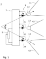
- Fig.1 1 schematically shows a lighting device 1 according to the invention with some basic components.
- the lighting device 1 comprises a light source arrangement 3 with several semiconductor-based light sources in the form of light-emitting diodes 31, 32, 33.
- a control circuit 7 is provided to which the light-emitting diodes 31, 32, 33 are connected, wherein the light-emitting diodes can be controlled individually to emit different light intensities.
- the light sources are preferably arranged rigidly or immovably. However, this does not rule out the possibility of the light sources having an adjustment option, for example for adjustment. Due to the fixed arrangement, the emitted light cones are immovable in relation to the lighting device.
- the lighting device 1 nevertheless enables a movable light field or, more generally, an adjustment of the spatial position of the light field through the mode of operation explained in more detail below.
- An adjusting device 5 is connected to the control circuit 7.
- a simple possibility for such an adjusting device 5 would be, for example, a potentiometer as shown.
- a large number of adjusting devices 5 are possible and the design of the Fig.1 is not limited to a specific control device.
- the control device 5 Depending on its position or the duration or type of actuation, the control device 5 generates a control signal, based on which the currents through the light-emitting diodes 31, 32, 33 and thus their light intensities are individually adjusted by the control circuit.
- the potentiometer is an example of an adjusting device 5 which interacts with the control circuit 7 in such a way that with a successive actuation of the adjusting means the center of gravity of the light field or its center axis progressively moves in one direction. If the rotary knob of the potentiometer is rotated successively in one direction, the light field and thus the center of gravity or the center axis of the light field moves in one direction by varying the light intensities of the LEDs 31, 32, 33; if rotated in the opposite direction, the light field also moves back in the opposite direction.
- a potentiometer is also an example of a sliding or rotary adjusting device (depending on whether it is a sliding or rotary potentiometer), whereby the adjusting device and the control circuit interact in such a way that different sliding or rotary positions of the sliding or rotary adjusting device correspond to different lighting directions.
- the center of gravity is understood to be the center of the light distribution, which is the mean of the spatial positions of the light distribution weighted by the light intensity.
- the center of gravity can therefore also be referred to as the spatial intensity center.
- the center axis of a light cone, or of the light field generated by one or more light cones, runs from the light source through the center of gravity, i.e. the intensity center.
- the light-emitting diodes 31, 32, 33 are further provided with collimation devices which collimate or focus the light of the light-emitting diodes 31, 32, 33 into light cones 41, 42, 43.
- the collimation devices are also referred to below as light bundling devices.
- the light cones 41, 42, 43 are generally directed differently by means of the light bundling devices 13, so that the light-emitting diodes illuminate different areas on an illuminated object.
- the light bundling devices 13 are designed so that adjacent light cones, i.e. those light cones that have the most similar directions overlap. In the representation of the Fig.1 the light cones 41 and 42 and the light cones 42 and 43 are adjacent. Accordingly, the areas of an illuminated object illuminated by the individual LEDs also overlap.
- the light bundling devices 13 can be designed for different positions in such a way that they collimate the light to different degrees, so that a light spot of the same size is achieved at the desired position (direction and distance). In order to keep the additional effort and/or the risk of confusion between different elements during assembly to a minimum, this can be achieved, for example, when using collimating lenses by adjusting the distance to the light-emitting diode.
- the control circuit 7 can now be set in one or more intermediate stages so that the LEDs of adjacent light cones are controlled and operated simultaneously.
- a light field is created whose center of gravity or central axis lies between the centers of gravity or central axes of the light fields or light cones of the individual LEDs 31, 32, 33.
- the center of gravity of the illuminated area can be shifted in the intermediate stages more towards one of the centers of gravity of the areas illuminated by the individual LEDs.
- the term “light cone” in the sense of the invention does not necessarily refer to a cone with a round cross-section. Rather, a light cone is generally understood to be a light field of any shape that widens with increasing distance. Accordingly, the area of an illuminated object illuminated by a light-emitting diode does not have to be round.
- the angle ⁇ between the directions of the centers of gravity or center axes of the light cones of maximum deflection, i.e. between the maximum deflection to the left and the maximum deflection to the right, is 30° to 80°, preferably 35° to 55°. This angle would correspond to the swivel angle in a mechanically pivotable lamp.
- the angle ⁇ can also be related to the number of different directions of the light cones. In the case of the Fig.1 In the example shown, at an angle of 30° to 60°, three light cones of different directions present. This means that each light cone covers 10° to 20° of the entire angle ⁇ .
- the lighting device 1 comprises several light-emitting diodes 31, 32, 33 with one or more light bundling devices 13, which emit light in several light cones 41, 42, 43 in different directions, with an angle in the range of 10° to 20° being included between the directions.
- This embodiment is in particular not limited to the Fig.1 shown number of three LEDs or three light cones.
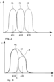
- Fig. 2 shows a schematic diagram of the light intensities of the light cones 41, 42, 43 along a location coordinate x, for example on an illuminated object.
- the focal points 410, 420, 430 of the light cones 41, 42, 43 are offset along the spatial coordinate due to their different directions.
- the adjacent light cones 41, 42, and 42, 43 overlap, so that in general, without being limited to the specific diagram, an area between the adjacent focal points is illuminated by both adjacent light cones.
- the example is also schematic with regard to the overlap of the individual light cones. The overlap is comparatively small. In practical applications, it is usually advisable to provide a larger overlap, although a smaller overlap, such as that shown, can also result in an aesthetically acceptable form of a pivoting light field.
- Fig.3 now shows an intermediate stage in the lighting in the same diagram.
- the two light-emitting diodes 31, 32 are operated together so that their light is emitted in the overlapping light cones 41, 42.
- the light-emitting diodes can now be operated by means of the adjusting device 5 such that the center of gravity of the light field 11 generated by the light-emitting diodes lies between the centers of gravity 410, 420 of the adjacent light cones 41, 42 when an intermediate stage is set.
- an intermediate stage is set in which the light cone 42 has a lower light intensity than the light cone 41.
- the center of gravity 11 of the light field 9 of the lighting device 1 is arranged between the centers of gravity 410, 420 in this setting and is shifted towards the center of gravity of the brighter light cone 410.
- the control circuit 7 is designed such that the respective currents through the light-emitting diodes 31, 32, 33 are selected such that the brightness of the light field 9 remains the same in various intermediate positions or fluctuates by a maximum of 20%, preferably a maximum of 10%.
- the currents through the LEDs and accordingly the light intensities of the light cones 41, 42 are reduced compared to the case where a light cone is generated with only one of the LEDs.
- the currents can also be adjusted such that the center brightness or maximum brightness in the intermediate positions remains the same or fluctuates by a maximum of 20%, preferably by a maximum of 10%.
- the intensities of the light cones 41, 42, 43 are adjusted accordingly, for example by further reducing the current through the LED 32 and further increasing the current through the LED 31 in order to shift the center of gravity of the light field 9 further towards the center of gravity 410 of the light cone 41 generated by the LED 31.
- this adjustment and readjustment can also be carried out gradually instead of abruptly setting the new parameters.
- control circuit 7 can be set up to set an intermediate position or the new parameters with a time delay when the actuating element 5 is actuated and the actuating value is thus changed, by setting the brightness of the LEDs 31, 32, 33, if they are involved, in a sliding manner over time or in several successive intermediate positions.
- the time delay and/or the parameters for controlling the light-emitting diodes via the various adjustable positions can be calculated in a microcontroller and/or stored as values in a memory of the control circuit.
- Fig.1 Three LEDs 31, 32, 33 are provided.
- the example of the Fig.3 but also shows that a displacement of the light field 9, or of its center of gravity 11, according to the invention is easily possible with just two light-emitting diodes.
- a major advantage of the invention is that the alignment of the light field can be carried out without mechanical parts. This not only enables a compact design, but also a robust and easy-to-clean configuration. Protruding mechanical components, which are more difficult to clean and ultimately increase the risk of injury, especially when used in vehicle or aircraft cabins, can be completely dispensed with.
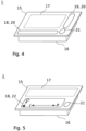
- the lighting device has a front panel behind which the light-emitting diodes are arranged.
- the lighting device can also be designed as a recessed light with a front panel.
- the recessed light comprises a housing 16 with a front panel 15 attached.
- the light-emitting diodes are arranged in the housing 16 and shine through the front panel 15 during operation.
- the control circuit 7 is preferably also accommodated in the housing 16.
- the front panel 15 has an operating element, or if an operating element is integrated into the front panel 15 with which the control device can be operated.
- the operating element comprises a touch element.
- the operating element is designed as a touch operating element.
- a touch-sensitive slider (a so-called “slider") is particularly advantageous for intuitive operation.
- an operating element 18 in the form of a touch-sensitive slider 20 is provided in order to actuate the adjusting device 5 or, more generally, to generate adjusting values for adjusting the beam direction of the lighting device 1.
- the embodiment with a common front panel for several light sources enables a very flat structure precisely due to the mode of operation with fixed light sources and movement of the light field by adjusting intermediate levels. There are clear advantages here, especially as a built-in light in vehicles or passenger cabins.
- a lighting device 1 which comprises a plurality of light sources, in particular a plurality of semiconductor-based light sources in the form of light-emitting diodes, as well as a common front panel for the plurality of light sources, wherein the front panel is at least partially transparent so that the light emitted by the light sources can pass through the front panel to the outside, wherein at least the transparent areas of the front panel are made of glass or plastic.
- This embodiment of the lighting device is also independent of the mode of operation with permanently installed light-emitting diodes and a movement of the light field by setting intermediate brightness levels.
- the light-emitting diodes are again installed in such a way that they emit light in light cones in different directions.
- the light sources can also simply emit light stationary in an immobile light field preset in terms of its spatial position.
- a control element for the user to move the light field does not then have to be provided.
- opaque areas of the front panel can be present due to opaque sections of the carrier material of the front panel or due to opaque coatings.
- the front panel is flat or uniaxially curved in order to ensure a good adaptation to the shape of larger panel parts in which the light is installed.
- control elements can also be used, as shown in the examples of the Fig. 4 and Fig. 5 are provided. As mentioned, touch controls are particularly suitable in order to keep the surface of the front panel flat.
- a touch-sensitive slide control 20 is not restricted to a recessed light with a front panel 15 as the lighting device 1. Rather, such a control element can also be used in other configurations. Accordingly, in one embodiment, a touch-sensitive control element 18, preferably a touch-sensitive slide control, is generally provided for actuating the adjusting device 5. This can be separate from the recessed light, for example in the form of a control element in an armrest and/or in the form of a remote control and/or as a control element in an entertainment system, for example with a touch-sensitive screen.
- an on-off switching element 21 is also provided. This can also be designed as a touch-sensitive operating element if it is integrated into the front panel 15.
- a further control device connected to the control circuit 7 in order to adjust the brightness of the light-emitting diodes 31, 32, 33, or the total light intensity emitted.
- a further control element 19 in the form of a touch-sensitive slider 20 is provided in order to be able to adjust the brightness of the lighting device 1.
- Fig.5 shows a variant of the embodiment according to Fig.4
- This variant is also designed as a recessed light with a front panel 15.
- no separate control elements 18, 19 are provided for brightness and direction.
- a single control element 18 is provided as a two-dimensional control panel in the form of a touch-sensitive matrix controller 22.
- the lighting direction can be adjusted in one direction and the brightness in the direction perpendicular to this can be adjusted by the position of the touch.
- control element is not integrated in the housing, or if an additional control element is provided that is separate from the built-in light. This applies in cases where the light is difficult to reach from the sitting or lying position, for example because there is no installation space available in a favorable position, because a favorable position is not desirable for reasons of design aesthetics, or because an easily accessible position is visually unfavorable. This can also be the case if the person has only limited mobility, e.g. in a hospital bed, but their position can be changed using the bed's electrical adjustment options, so that the lighting direction must also be adapted to the respective situation in order to use the light.
- a mechanically adjustable light would require a motor to change the setting of the light cone in response to a signal from the control device (18, 19).
- a control element can be integrated in an armrest of a seat to be illuminated with the lighting device.
- the control element can comprise a remote control.
- the front panel 15 can be opaque for aesthetic reasons.
- a window 17 can then be provided behind which the LEDs 31, 32, 33 are arranged and which lets the light from the LEDs through.
- the window 17 can in turn be provided with a coating or masking in order to achieve a so-called dead-front effect.
- the interior of the lighting device is illuminated by the Coating or masking conceals the viewer, but the LEDs can shine through the coating or masking.
- a semi-transparent coating that sufficiently darkens the inside of the housing.
- Another example is masking in the form of a structured coating that leaves small areas of the aperture free, for example in a grid pattern, through which the light from the LEDs can escape.
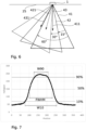
- Fig.6 shows an embodiment for the configuration of the lighting parameters of a lighting device 1 according to the invention.
- the lighting device 1 is designed as a ceiling light that can be installed in a ceiling 25 of the interior of a vehicle or aircraft.
- the light-emitting diodes of the lighting device emit light cones 41, 42, 43, each of which has an opening angle of 60°.
- the directions of adjacent, overlapping light cones in this example each have an angle of 15°.
- the direction of the light cone 43 to the light cone 41 has an angle of 30°.
- the adjacent light cones overlap, but also the next but one light cones, i.e. in the example shown the light cones 41 and 43.
- one embodiment of the invention provides that at least some of the light-emitting diodes 31, 32, 33 are collimated such that the opening angle of the light cones 41, 42, 43 is greater than the angle between the light cones, or between the center axes 411, 421, 431 of the light cones.
- the light-emitting diodes 31, 32, 33 are collimated such that the angle between adjacent light cones is at most equal to half the opening angle of the light cones 41, 42, 43.
- the overlap is expressed in such a way that at least some of the light-emitting diodes 31, 32, 33 are collimated so that at least one of the light cones overlaps both with a second, adjacent light cone and with a third light cone which is adjacent to the second light cone.
- the features described above serve to achieve a smooth transition of the shape of the light fields when moving the light field or when swiveling the resulting light cone in the intermediate positions.
- a so-called top hat profile with a sharp border is therefore rather disadvantageous.
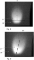
- Fig.7 shows a brightness gradient on an illuminated surface along a line, as generated by one of the collimated light-emitting diodes.
- a photographic image of the associated light spot 27 on a surface 28 illuminated by the lighting device 1 shows Fig.8 .
- the line along which the brightness gradient was extracted from the gray values of the image is shown in Fig.8 as a horizontal bar, which runs through the brightness maximum of the light spot 27.
- Three lines are drawn which mark the levels of 10%, 50% and 90% of the maximum brightness. The width of the brightness distribution at the 50% line is therefore the half-width of the distribution.
- a distribution which is favourable to support an optical impression of a light spot which can be continuously adjusted in its position can be achieved if the flanks do not rise too abruptly, as explained above.
- the values W90, W10 and FWHM are in Fig.7 Without being limited to the examples shown, it is preferred if the above-mentioned parameter has a value of at least 0.5. On the other hand, it is also advantageous not to let the distribution become too flat. In this case, the light field would become too wide, which is undesirable in a reading light, for example, since the brightness is to be concentrated on the object to be illuminated. The pivoting of the light field is then also less clearly perceptible. According to another embodiment, it is therefore provided that the above-mentioned parameter (W10-W90) / FWHM has a value of less than 1.6.
- the brightness distribution of the light of one of the light-emitting diodes preferably all light-emitting diodes 31, 32, 33 on a surface 28 illuminated by the lighting device 1 along a line through the brightness maximum of the light distribution of the parameters (W10-W90) / FWHM has a value in the range of 0.5 to 1.6.
- the Fig. 9 to 11 show further photographic images of the area illuminated by a lighting device, or light spot 27 on a surface 28.
- the Fig. 8 to 10 show light spots 27, which are formed by light cones of individual light-emitting diodes 31, 32, 33, but according to the Fig.6 shown configuration were created at different angles.
- the angle is 0°
- the light cone has to the light cone to Fig.8 an angle of 15°
- in the example of Fig.10 an angle of 30°.
- the light spot is created by superimposing adjacent light cones of two light-emitting diodes, or by superimposing the light spots from Fig.9 and Fig.10
- the light intensity of both LEDs is halved, so that the total brightness of the light field corresponds to that of the light cones of the individual LEDs.
- This superposition results in an effective angle of the central axis, or the direction of the center of gravity, to the direction of the center of gravity of the light spot from Fig.8 of 22.5°.
- the extension of the light spot at the intermediate position is Fig. 11 not noticeably enlarged.
- Fig. 12 shows various possibilities for the construction of a lighting device 1, with which a collimation of the light from the LEDs into light cones in different directions is possible.
- the LEDs 31, 32, 33 are mounted on pedestals 35, as shown in example (a), which have partially inclined holding surfaces, so that the LEDs 31, 32, 33 together with the light bundling devices 13 are tilted at the intended angle with respect to the surface of the circuit board.
- the LEDs can be attached to inclined mounting elements on a base, in particular a circuit board.
- Lenses are provided here as collimating elements 13, for example.
- suitable collimating elements or light bundling devices 13 can also be provided, which capture unwanted light emitted from the side.
- open tubes can cover the LEDs at the sides for this purpose.
- a base 37 with a curved surface is provided. If the light-emitting diodes 31, 32, 33 are connected to the light bundling devices 13 with this base, they assume a certain angle according to the local inclination of the surface. inclination.
- a flexible circuit board 29 can also be provided for this purpose, on which the light-emitting diodes are mounted.
- optical deflection elements 38 can generally be provided in order to generate light cones in different directions.
- This embodiment offers the advantage that the light-emitting diodes can be mounted directly on a flat circuit board 29.
- the function of the light bundling devices 13 and the deflection elements 38 can also be combined in an optical element (not shown). This is then designed, for example, as an optical free-form element.
- the optical elements can also be particularly advantageously integrated into the housing cover or the front panel.
- the front panel can have sections shaped as lenses.
- optical elements can also be located as elements of a component on a common base plate.
- this would be a lens array and in example 12 (c) an array of free-form elements. This can simplify the manufacture of the optical elements and also the assembly in the luminaire.
- Fig. 13 shows a swivel line 45 of an area illuminated by a conventional lighting device when a surface is illuminated at an angle.
- the light field 9 moves along this swivel line 45 when the light source is mechanically swiveled between an angle of -30° and an angle of +30° and the surface to be illuminated is illuminated at an angle. Since the swivel axis is at an angle to the surface, the line is not straight.
- the swivel line represents the edge of a conic section and is typically a hyperbola.
- a pivot line 45 of basically any shape can now be set by suitable alignment of the individual light sources and light bundling devices 13, even when an area to be illuminated is illuminated at an angle.
- Fig. 14 an area to be illuminated is illuminated at an angle by the lighting device 1.
- the individual light cones of the LEDs are aligned in such a way that these support points lie on a straight line. Accordingly, the intermediate positions created by superimposing the light cones also lie on the straight pivot line 45. Differently shaped paths or pivot lines 45 can also be created by appropriately aligning the light cones of the LEDs.
- FIG. 15 shows another example in which part of the swivel line 45 is deviated from a straight path Such a path could be desirable, for example, if part of the surface to be illuminated is curved, so that the non-linear path of the swivel line compensates for the curvature and the impression of a straight-line swivel is created.
- the embodiments of the Fig. 14 and Fig. 15 What is common, without limitation to the specific embodiments shown, is that the beam directions of the light cones of the at least three light-emitting diodes do not all lie in one plane.
- the light spot positions generated by the lighting device can therefore be arranged along a - not necessarily straight - one-dimensional line.
- they can also cover a two-dimensional field, so that the positions can be adjusted not only in one but in two dimensions.
- any light spot position can be achieved not by blending just two light cones, but by several light cones, in particular three light cones in a triangular arrangement or four light cones in a square or rectangular arrangement.
- Fig. 16 shows an exemplary embodiment.
- the directions of the light cones of the LEDs, or the light spots generated by the light cones, are distributed in two spatial directions, so that the light field can be swiveled within a two-dimensional swivel range 46 by superimposing the light cones and setting intermediate positions.
- the swivel range 46 is a rectangular area in the example shown, but can also have any other shape.
- the invention provides that the light cones of the light-emitting diodes 31, 32, 33 are aligned such that the areas illuminated by the light cones are distributed in two spatial directions, so that by superimposing the light cones and thus by setting intermediate positions, the light field 9, or the area illuminated by the lighting device 1, can be moved, preferably pivoted, within a two-dimensional pivoting range 46.
- the lighting device 1 can be used in particular as a reading light for adjustable seating or reclining furniture, in which the position of the area to be illuminated changes with the sitting or reclining position. Typical applications for this are reading lights in airplanes, ships, trains, automobiles or other vehicles. In addition, this light is also particularly suitable for adjustable beds, in particular for hospital beds in hospitals or similar facilities.
- Lighting device 3 Light source arrangement 5 Adjustment device 7 Control circuit 9 Light field 11 Focus of 9 13 Light bundling device 15 Front panel 16 Housing 17 Window 18, 19 Control element 20 touch-sensitive slider 21 On-off switching element 22 touch-sensitive matrix controller 25 Ceiling 27 Light spot 28 illuminated area 29 Circuit board 31, 32, 33 LED 35 Podium 37 Base with curved surface 38 optical deflection element 41, 42, 43 Light cone 45 Swing line 46 two-dimensional swivel range 50 Sliding adjustment device 51 Rotary adjustment device 410, 420, 430 Focus of the light cones 411, 421, 431 Center axes of the light cones
Landscapes
- Engineering & Computer Science (AREA)
- General Engineering & Computer Science (AREA)
- Mechanical Engineering (AREA)
- Theoretical Computer Science (AREA)
- Human Computer Interaction (AREA)
- Physics & Mathematics (AREA)
- General Physics & Mathematics (AREA)
- Microelectronics & Electronic Packaging (AREA)
- Arrangements Of Lighting Devices For Vehicle Interiors, Mounting And Supporting Thereof, Circuits Therefore (AREA)
- Fastening Of Light Sources Or Lamp Holders (AREA)
- Non-Portable Lighting Devices Or Systems Thereof (AREA)
Description
Die Erfindung betrifft allgemein halbleiterbasierte Beleuchtungseinrichtungen. Insbesondere betrifft die Erfindung Leuchten mit einem räumlich veränderlichen Lichtfeld.The invention relates generally to semiconductor-based lighting devices. In particular, the invention relates to luminaires with a spatially variable light field.
Hinsichtlich des zu beleuchtenden Orts einstellbare Leuchten werden insbesondere als Leseleuchten eingesetzt. Hier sollte die Beleuchtungsrichtung und damit der zu beleuchtende Ort leicht einstellbar sein, um einerseits eine lokale Beleuchtung bereitzustellen, andererseits auf wechselnde Positionen des Nutzers anpassbar zu sein. Um dies zu erreichen, werden die Leuchten mit einem beweglichen Kopf ausgerüstet, der eine Schwenkung des von der Leuchte erzeugten Lichtkegels gestattet. Eine solche Leselampe ist beispielsweise in der
Eine andere Lösung sieht die
Der Erfindung liegt daher die Aufgabe zugrunde, eine Beleuchtungseinrichtung nach Anspruch 1 anzugeben, die kompakt und wenig anfällig, beziehungsweise wartungsarm ist und eine einfache Ausrichtung des Beleuchtungsfelds, beziehungsweise Lichtfeldes gestattet. Diese Aufgabe wird durch den Gegenstand der unabhängigen Ansprüche gelöst. Vorteilhafte Ausgestaltungen der Erfindung sind in den abhängigen Ansprüchen angegeben.The invention is therefore based on the object of specifying a lighting device according to
Demgemäß sieht die Erfindung eine Beleuchtungsvorrichtung mit einer Lichtquellenanordnung mit mehreren halbleiterbasierten Lichtquellen in Form von Leuchtdioden vor, welche so kollimiert sind, dass diese jeweils Licht in unterschiedlich gerichtete Lichtkegel emittieren, derart, dass benachbarte Lichtkegel überlappen, und wobei die Beleuchtungsvorrichtung eine Stelleinrichtung zur Abgabe eines Stellsignals für die Einstellung der Beleuchtungsrichtung und eine Ansteuerschaltung aufweist, welche mit der Stelleinrichtung verbunden ist, wobei mit der Stelleinrichtung Zwischenstufen einstellbar sind, bei welchen die Leuchdioden benachbarter und überlappender Lichtkegel von der Ansteuerschaltung gemeinsam und in variierender Lichtintensität so betreibbar sind, dass die Mittenachse, beziehungsweise der Schwerpunkt des von den Leuchtdioden erzeugten Lichtfelds bei den Zwischenstufen jeweils zwischen den Mittenachsen, beziehungsweise Schwerpunkten benachbarter Lichtkegel liegt.Accordingly, the invention provides a lighting device with a light source arrangement with several semiconductor-based light sources in the form of light-emitting diodes, which are collimated such that they each emit light in differently directed light cones, such that adjacent light cones overlap, and wherein the lighting device has an adjusting device for emitting an adjusting signal for adjusting the direction of illumination and a control circuit which is connected to the adjusting device, wherein intermediate stages can be set with the adjusting device, in which the light-emitting diodes of adjacent and overlapping light cones can be operated jointly by the control circuit and in varying light intensity such that the center axis or the center of gravity of the light field generated by the light-emitting diodes in the intermediate stages lies between the center axes or centers of gravity of adjacent light cones.
Die Leuchtdioden einer erfindungsgemäßen Beleuchtungseinrichtung werden demgemäß nicht diskret ein- oder ausgeschaltet, um eine bestimmte Beleuchtungsrichtung, beziehungsweise die Ausleuchtung eines vorgesehenen Bereichs zu erzielen. Vielmehr werden benachbarte Lichtfelder mit unterschiedlicher Intensität überlagert, um insgesamt ein Lichtfeld zu erhalten, welches örtlich oder richtungsmäßig zwischen benachbarten Lichtfeldern einzeln betriebener, in unterschiedliche Richtung strahlender Leuchtdioden liegt. Auf diese Weise kann bereits mit einer relativ geringen Anzahl von Leuchtdioden eine kontinuierliche oder wenigstens quasikontinuierliche Ausrichtung der Beleuchtungsrichtung erreicht werden. Die Beleuchtungsvorrichtung kann bevorzugt als Leseleuchte ausgebildet sein,The light-emitting diodes of a lighting device according to the invention are therefore not discretely switched on or off in order to achieve a specific lighting direction or the illumination of a designated area. Rather, adjacent light fields with different intensities are superimposed in order to obtain an overall light field which is located locally or directionally between adjacent light fields of individually operated light-emitting diodes radiating in different directions. In this way, a continuous or at least quasi-continuous alignment of the lighting direction can be achieved with a relatively small number of light-emitting diodes. The lighting device can preferably be designed as a reading light.
Der Begriff "kollimiert" bezeichnet im Sinne dieser Offenbarung keine strenge Parallelrichtung, die ohnehin nur mit idealen punktförmigen Lichtquellen theoretisch möglich wäre, sondern allgemein die Erzeugung gerichteten Lichts, nämlich von Licht, das in besagten Lichtkegel abgegeben wird. In dieser Offenbarung wird der Begriff "kollimiert" daher auch synonym mit dem Begriff "gerichtet" oder "gebündelt" verwendet. Demgemäß kann die Beleuchtungsvorrichtung gemäß dieser Offenbarung auch wie folgt beschrieben werden: Es ist eine Beleuchtungsvorrichtung mit einer Lichtquellenanordnung mit mehreren halbleiterbasierten Lichtquellen in Form von Leuchtdioden vorgesehen, deren emittiertes Licht so gebündelt wird, dass es unterschiedlich gerichtete Lichtkegel bildet, die sich in einem Lichtfeld überlappen, wobei die Beleuchtungsvorrichtung eine Stelleinrichtung zur Abgabe eines Stellsignals für die Einstellung der Beleuchtungsrichtung und eine Ansteuerschaltung aufweist, welche mit der Stelleinrichtung verbunden ist, wobei mit der Stelleinrichtung Zwischenstufen einstellbar sind, bei welchen Leuchtdioden benachbarter und überlappender Lichtkegel von der Ansteuerschaltung gemeinsam und in variierbarer Lichtintensität so betreibbar sind, dass der Schwerpunkt des von den Leuchtdioden erzeugten Lichtfelds bei den Zwischenstufen zwischen den Schwerpunkten benachbarter Lichtkegel liegt.The term "collimated" in the sense of this disclosure does not refer to a strict parallel direction, which would theoretically only be possible with ideal point-shaped light sources anyway, but rather generally to the generation of directed light, namely light that is emitted in said light cone. In this disclosure, the term "collimated" is therefore also used synonymously with the term "directed" or "bundled". Accordingly, the lighting device according to this disclosure can also be described as follows: It is a lighting device with a light source arrangement with several semiconductor-based Light sources in the form of light-emitting diodes are provided, the emitted light of which is bundled in such a way that it forms differently directed light cones which overlap in a light field, wherein the lighting device has an adjusting device for emitting an adjusting signal for adjusting the direction of illumination and a control circuit which is connected to the adjusting device, wherein intermediate stages can be set with the adjusting device, in which light-emitting diodes of adjacent and overlapping light cones can be operated jointly by the control circuit and in variable light intensity in such a way that the center of gravity of the light field generated by the light-emitting diodes lies at the intermediate stages between the centers of gravity of adjacent light cones.
Für die Beleuchtungseinrichtung kann also in bevorzugter Weise auch bei ortsfesten Lichtkegeln eine räumliche Einstellung des Ausleuchtungsbereichs durch Variation der Helligkeit der einzelnen Lichtkegel in den Zwischenstufen erfolgen. Mit der Einstellung kann auch ein räumlich fixes, beziehungsweise ortsfestes Lichtfeld eingestellt werden, wobei diese Einstellungen nach Vorgabe, beispielsweise bei einer Konfiguration der Beleuchtungseinrichtung veränderbar sind. Gemäß einer Ausführungsform wird dazu die Beleuchtungseinrichtung vor einer Nutzung, beispielsweise als Leseleuchte so konfiguriert, dass diese einen bestimmten Bereich fest ausleuchtet. In einfachster Ausgestaltung braucht dann auch kein für den Nutzer zugängliches Bedienelement zur Bewegung des Lichtfelds vorgesehen sein.For the lighting device, a spatial adjustment of the illumination area can therefore preferably be carried out by varying the brightness of the individual light cones in the intermediate stages, even with stationary light cones. The adjustment can also be used to set a spatially fixed or stationary light field, whereby these settings can be changed as required, for example when configuring the lighting device. According to one embodiment, the lighting device is configured before use, for example as a reading light, so that it permanently illuminates a certain area. In the simplest embodiment, no control element accessible to the user for moving the light field needs to be provided.
Diese räumliche Einstellung kann aber auch eine Bewegung, insbesondere eine Schwenkung des Lichtfelds umfassen.However, this spatial adjustment can also include a movement, in particular a pivoting of the light field.
Jedenfalls wird die Bewegung des Lichtfelds vorzugsweise nicht, oder zumindest nicht alleine durch Schwenkung eines oder mehrerer Lichtkegel, sondern vielmehr durch eine Helligkeitseinstellung bewirkt. Es ist also vorgesehen, dass die Lichtquellen jeweils in einen unbeweglichen Lichtkegel Licht abstrahlen und vorzugsweise ortsfest angeordnet sind.In any case, the movement of the light field is preferably not, or at least not solely, caused by pivoting one or more light cones, but rather by adjusting the brightness. It is therefore intended that the light sources each emit light into an immobile light cone and are preferably arranged in a fixed location.
Denkbar wäre etwa, die gewünschte Position, beziehungsweise Richtung des Lichtfelds in einer Form von Koordinaten, beispielsweise als Zahl innerhalb eines die verschiedenen Richtungen repräsentierenden Zahlenbereichs in die Stelleinrichtung einzugeben. Eine besonders intuitive Bedienung kann aber erzielt werden, wenn die Stelleinrichtung und die Ansteuerschaltung so zusammenwirken, dass mit einer sukzessiven Betätigung des Stellmittels sich der Schwerpunkt des Lichtfelds bewegt, beispielsweise geradlinig in eine Richtung. Eine weitere, besonders bevorzugte Möglichkeit ist, eine Stelleinrichtung vorzusehen, die eine Schiebe- oder Dreheinstelleinrichtung umfasst, wobei die Stelleinrichtung und die Ansteuerschaltung so zusammenwirken, dass verschiedenen Schiebe- oder Drehstellungen der Schiebe- oder Dreheinstelleinrichtung mit verschiedenen Beleuchtungsrichtungen korrespondieren.It would be conceivable, for example, to enter the desired position or direction of the light field in the form of coordinates, for example as a number within a number range representing the different directions, into the adjusting device. However, particularly intuitive operation can be achieved if the adjusting device and the control circuit work together in such a way that the center of gravity of the light field moves with a successive actuation of the adjusting means, for example in a straight line in one direction. Another, particularly preferred possibility is to provide an adjusting device which comprises a sliding or rotary adjustment device, wherein the adjusting device and the Control circuits interact in such a way that different sliding or rotating positions of the sliding or rotating adjustment device correspond to different lighting directions.
Nicht nur die Position des von der Beleuchtungseinrichtung beleuchteten Bereichs soll sich in Zwischenpositionen zwischen den Positionen der Lichtflecken, beziehungsweise ausgeleuchteten Bereiche mittels der Erfindung möglichst gleichmäßig bewegen lassen. Auch wäre es dabei wünschenswert, wenn die Einstellung verschiedener Positionen möglichst ohne merkliche Helligkeitsschwankungen bewerkstelligt wird. Dazu ist gemäss der Erfindung vorgesehen, dass die Ansteuerschaltung ausgebildet ist, die Leuchtdioden so anzusteuern, dass die Helligkeit des Lichtfelds in den verschiedenen Zwischenstufen gleichbleibt oder um maximal 20%, vorzugsweise maximal 10% schwankt. Gemäß einer anderen, alternativen oder zusätzlichen Ausführungsform kann die Einstellung der Leuchtdioden durch die Ansteuerschaltung, typischerweise über die Ströme auch so erfolgen, dass die Mittenhelligkeit oder Maximalhelligkeit in den Zwischenpositionen, beziehungsweise Zwischenstufen gleich bleibt oder um maximal 20%, vorzugsweise um maximal 10% schwankt. Unter Umständen kann eine Schwankung der Maximalhelligkeit, typischerweise in der Mitte des Lichtfelds oder in der Nähe des Schwerpunkts deutlicher sichtbar sein, als eine Schwankung der Gesamthelligkeit.Not only should the position of the area illuminated by the lighting device be able to move as evenly as possible in intermediate positions between the positions of the light spots or illuminated areas by means of the invention. It would also be desirable if the setting of different positions could be accomplished without noticeable fluctuations in brightness. To this end, according to the invention, the control circuit is designed to control the LEDs in such a way that the brightness of the light field in the various intermediate stages remains the same or fluctuates by a maximum of 20%, preferably a maximum of 10%. According to another, alternative or additional embodiment, the setting of the LEDs by the control circuit, typically via the currents, can also be carried out in such a way that the center brightness or maximum brightness in the intermediate positions or intermediate stages remains the same or fluctuates by a maximum of 20%, preferably a maximum of 10%. Under certain circumstances, a fluctuation in the maximum brightness, typically in the center of the light field or near the center of gravity, can be more clearly visible than a fluctuation in the overall brightness.
Gemäß einer Weiterbildung der Erfindung ist die Ansteuerschaltung außerdem so ausgebildet, unter Ansprechen auf die Änderung eines Stellwert des Stellelements eine Einstellung einer Zwischenstellung mit einer Zeitverzögerung vorzunehmen, dergestalt, dass die Helligkeiten der Leuchtdioden zeitlich gleitend oder in mehreren Zwischenstellungen eingestellt werden. Damit wird nicht nur eine angenehmere Bedienung erreicht, sondern die gleitende Einstellung erleichtert für eine Bedienperson auch das leichtere Auffinden einer optimalen Beleuchtung.According to a further development of the invention, the control circuit is also designed to set an intermediate position with a time delay in response to the change in a control value of the control element, such that the brightness of the LEDs is set gradually over time or in several intermediate positions. This not only makes operation more pleasant, but the smooth setting also makes it easier for an operator to find the optimal lighting.
Die Erfindung wird nachfolgend genauer und anhand der Zeichnungen erläutert. In den Zeichnungen verweisen gleiche Bezugszeichen jeweils auf gleiche oder entsprechende Elemente.The invention is explained in more detail below with reference to the drawings. In the drawings, like reference numerals refer to like or corresponding elements.
- Fig. 1Fig.1
- zeigt eine Beleuchtungsvorrichtung.shows a lighting device.
- Fig. 2Fig.2
- zeigt ein Diagramm der Intensitätsverteilungen der Lichtkegel der Leuchtdiodenshows a diagram of the intensity distributions of the light cones of the LEDs
- Fig. 3Fig.3
- zeigt als Diagramm die Überlagerung zweier Lichtkegel.shows a diagram of the superposition of two light cones.
- Fig. 4Fig.4
- stellt eines Ausführungsform einer Beleuchtungseinrichtung mit einer Frontblende dar.represents an embodiment of a lighting device with a front panel.
- Fig. 5Fig.5
-
zeigt eine Variante der in
Fig. 4 dargestellten Ausführungsform.shows a variant of theFig.4 illustrated embodiment. - Fig. 6Fig.6
-
zeigt ein Ausführungsbeispiel einer Beleuchtungsvorrichtung 1 mit den von den Leuchtdioden abgestrahlten Lichtkegeln.shows an embodiment of a
lighting device 1 with the light cones emitted by the light-emitting diodes. - Fig. 7Fig.7
- ist ein Diagramm des Helligkeitsverlaufs des von einer Leuchdiode erzeugten Lichtfelds.is a diagram of the brightness curve of the light field generated by a light-emitting diode.
- Fig. 8 bis Fig. 11Fig. 8 to Fig. 11
- zeigen fotografische Aufnahmen des von einer Beleuchtungsvorrichtung ausgeleuchteten Bereichs auf einer Fläche.show photographic images of the area on a surface illuminated by a lighting device.
- Fig. 12Fig. 12
- zeigt verschiedene Konfigurationen des Aufbaus einer Beleuchtungsvorrichtung.shows different configurations of the structure of a lighting device.
- Fig. 13Fig. 13
- zeigt eine Schwenklinie eines beleuchteten Bereichs bei schräger Beleuchtung einer Fläche mit einer herkömmlichen Beleuchtungseinrichtung.shows a panning line of an illuminated area when an area is obliquely illuminated with a conventional lighting device.
- Fig. 14 und 15Figs. 14 and 15
- zeigen Schwenklinien, wie sie das Lichtfeld der Beleuchtungseinrichtung gemäß einer Ausführungsform der Erfindung bei einer Bewegung abfährt.show swivel lines as the light field of the lighting device according to an embodiment of the invention moves during a movement.
- Fig. 16Fig. 16
- zeigt eine Ausführungsform mit einem zweidimensionalen Schwenkbereich.shows an embodiment with a two-dimensional swivel range.
In
Die Beleuchtungsvorrichtung 1 umfasst Lichtquellenanordnung 3 mit mehreren halbleiterbasierten Lichtquellen in Form von Leuchtdioden 31, 32, 33. Es ist eine Ansteuerschaltung 7 vorgesehen, an welche die Leuchtdioden 31, 32, 33 angeschlossen sind, wobei die Leuchtdioden individuell zur Abgabe unterschiedlicher Lichtintensitäten ansteuerbar sind. Die Lichtquellen sind vorzugsweise starr, beziehungsweise unbeweglich angeordnet. Dies schließt aber nicht aus, dass die Lichtquellen doch eine Einstellmöglichkeit, beispielsweise zur Justage aufweisen. Durch die feststehende Anordnung sind die abgegebenen Lichtkegel unbeweglich in Bezug auf die Beleuchtungseinrichtung. Die Beleuchtungsvorrichtung 1 ermöglicht durch die unten genauer erläuterte Betriebsweise dennoch ein bewegliches Lichtfeld oder allgemeiner eine Einstellung der räumlichen Lage des Lichtfelds.The
An die Ansteuerschaltung 7 ist eine Stelleinrichtung 5 angeschlossen. Eine einfache Möglichkeit einer solchen Stelleinrichtung 5 wäre beispielsweise wie dargestellt ein Potentiometer. Es ist aber eine Vielzahl von Stelleinrichtungen 5 möglich und die Ausführungsform der
Das Potentiometer ist ein Beispiel für eine Stelleinrichtung 5, die mit der Ansteuerschaltung 7 so zusammenwirkt, dass mit einer sukzessiven Betätigung des Stellmittels sich der Schwerpunkt des Lichtfelds, beziehungsweise dessen Mittenachse fortschreitend in eine Richtung bewegt. Wird der Drehknopf des Potentiometers sukzessive in eine Richtung gedreht, wandert durch Variation der Lichtintensitäten der Leuchtdioden 31, 32, 33 das Lichtfeld und damit der Schwerpunkt, beziehungsweise die Mittenachse des Lichtfelds in eine Richtung, bei Drehung in die entgegengesetzte Richtung wandert auch das Lichtfeld in entgegengesetzter Richtung zurück. Außerdem stellt ein Potentiometer ein Beispiel für eine Schiebe- oder Dreheinstelleinrichtung dar (je nachdem, ob es sich um ein Schiebe- oder Drehpotentiometer handelt), wobei die Stelleinrichtung und die Ansteuerschaltung so zusammenwirken, dass verschiedene Schiebe- oder Drehstellungen der Schiebe- oder Dreheinstelleinrichtung mit verschiedenen Beleuchtungsrichtungen korrespondieren.The potentiometer is an example of an
Als Schwerpunkt wird im Sinne der Erfindung der Mittelpunkt der Lichtverteilung verstanden, der sich aus der mit der Lichtintensität gewichteten Mittel der Ortspositionen der Lichtverteilung. Der Schwerpunkt kann daher auch als räumlicher Intensitätsmittelpunkt bezeichnet werden. Die Mittenachse eines Lichtkegels, beziehungsweise des von einem oder mehreren Lichtkegeln erzeugte Lichtfeld läuft von der Lichtquelle ausgehend durch den Schwerpunkt, also den Intensitätsmittelpunkt.In the sense of the invention, the center of gravity is understood to be the center of the light distribution, which is the mean of the spatial positions of the light distribution weighted by the light intensity. The center of gravity can therefore also be referred to as the spatial intensity center. The center axis of a light cone, or of the light field generated by one or more light cones, runs from the light source through the center of gravity, i.e. the intensity center.
Die Leuchtdioden 31, 32, 33 sind weiterhin mit Kollimierungseinrichtungen versehen, welche das Licht der Leuchtdioden 31, 32, 33 jeweils in Lichtkegel 41 , 42, 43 kollimieren, beziehungsweise bündeln. Die Kollimierungseinrichtungen werden nachfolgend auch als Lichtbündelungseinrichtungen bezeichnet. Wie schematisch dargestellt sind die Lichtkegel 41, 42, 43 allgemein mittels der Lichtbündelungseinrichtungen 13 unterschiedlich gerichtet, so dass die Leuchtdioden auf einem angeleuchteten Objekt unterschiedliche Bereiche ausleuchten. Die Lichtbündelungseinrichtungen 13 sind so ausgelegt, dass benachbarte Lichtkegel, also diejenigen Lichtkegel, die jeweils die ähnlichsten Richtungen aufweisen, überlappen. In der Darstellung der
Da sich mit der Position des Lichtkegels auch die Entfernung zur Beleuchtungseinrichtung ändert, können die Lichtbündelungseinrichtungen 13 für unterschiedliche Positionen so ausgeführt sein, dass sie das Licht unterschiedlich stark kollimieren, so dass an der jeweils gewünschten Position (Richtung und Entfernung) ein Leuchtfleck der gleichen Größe erzielt wird. Um den zusätzlichen Aufwand und / oder die Verwechslungsgefahr zwischen verschiedenen Elementen bei der Montage gering zu halten, kann dies beispielsweise bei der Verwendung von Kollimierungslinsen durch eine Anpassung des Abstands zur Leuchtdiode erreicht werden.Since the distance to the lighting device changes with the position of the light cone, the
Mit der Stelleinrichtung 5 kann die Ansteuerschaltung 7 in einer oder mehreren Zwischenstufen nun so eingestellt werden, dass die Leuchtdioden benachbarter Lichtkegel gleichzeitig angesteuert und betrieben werden. Es ergibt sich bei der Einstellung einer Zwischenstufe ein Lichtfeld, dessen Schwerpunkt oder Mittenachse zwischen den Schwerpunkten oder Mittenachsen der Lichtfelder, beziehungsweise Lichtkegel der einzelnen Leuchtdioden 31, 32, 33 liegt. Je nach Verhältnis der Lichtintensitäten der Leuchtdioden kann in den Zwischenstufen der Schwerpunkt des ausgeleuchteten Bereiches mehr zu einem der Schwerpunkte der von den einzelnen Leuchtdioden beleuchteten Bereiche verschoben werden.Using the adjusting
Allgemein bezeichnet der Begriff eines Lichtkegels im Sinne der Erfindung nicht zwangsläufig einen Kegel mit rundem Querschnitt. Unter einem Lichtkegel wird vielmehr allgemein ein sich mit wachsender Entfernung aufweitendes Lichtfeld mit beliebiger Form verstanden. Demgemäß muss der von einer Leuchtdiode ausgeleuchtete Bereich eines beleuchteten Objekts auch nicht rund sein.In general, the term “light cone” in the sense of the invention does not necessarily refer to a cone with a round cross-section. Rather, a light cone is generally understood to be a light field of any shape that widens with increasing distance. Accordingly, the area of an illuminated object illuminated by a light-emitting diode does not have to be round.
Erfindungsgemäss beträgt der Winkel α zwischen den Richtungen der Schwerpunkte oder Mittenachsen der Lichtkegel der maximalen Auslenkung, also etwa zwischen der maximalen Auslenkung nach links zur maximalen Auslenkung nach rechts 30° bis 80°, vorzugsweise 35° bis 55°. Dieser Winkel entspräche bei einer mechanisch schwenkbaren Leuchte dem Schwenkwinkel. Der Winkel α kann gemäß einer Ausführungsform auch in Beziehung zur Anzahl der verschiedenen Richtungen der Lichtkegel gesetzt werden. Bei dem in
Soll nun eine andere Zwischenstellung angefahren werden, um das Lichtfeld 9 auf einen bestimmten auszuleuchtenden Bereich auszurichten, werden die Intensitäten der Lichtkegel 41, 42, 43 entsprechend angepasst, beispielsweise, indem der Strom durch die Leuchtdiode 32 weiter abgesenkt und der Strom durch die Leuchtdiode 31 weiter angehoben wird, um den Schwerpunkt des Lichtfelds 9 weiter in Richtung auf den Schwerpunkt 410 des von der Leuchtdiode 31 erzeugten Lichtkegels 41 zu schieben. Diese Anpassung und Neueinstellung kann nach einer Ausführungsform anstelle einer sprunghaften Einstellung der neuen Parameter insbesondere auch allmählich erfolgen. Dazu kann die Ansteuerschaltung 7 eingerichtet sein, bei einer Betätigung des Stellelements 5 und damit einer die Änderung des Stellwerts eine Einstellung einer Zwischenstellung, beziehungsweise der neuen Parameter mit einer Zeitverzögerung vorzunehmen, indem die Helligkeiten der Leuchtdioden 31, 32, 33, sofern diese beteiligt sind, zeitlich gleitend oder in mehreren sukzessive Zwischenstellungen eingestellt werden. Gemäß einer Weiterbildung dieser Ausführungsform der Erfindung können die Zeitverzögerung und/oder die Parameter zur Ansteuerung der Leuchtdioden über die verschiedenen einstellbaren Positionen in einem Mikrocontroller berechnet und/oder als Werte in einem Speicher der Ansteuerschaltung hinterlegt sein.If a different intermediate position is to be approached in order to align the
Bei dem Beispiel der
Ein großer Vorteil der Erfindung ist, dass das Ausrichten des Lichtfelds ohne mechanische Teile erfolgen kann. Dies ermöglicht nicht nur einen kompakten Aufbau, sondern auch eine robuste und leicht reinigbare Konfiguration. Auf hervorstehende mechanische Bauteile, die schwieriger zu reinigen sind und letztendlich, besonders auch bei der Verwendung in Fahrzeug- oder Flugzeugkabinen das Verletzungsrisiko erhöhen, kann vollständig verzichtet werden. Diese Vorteile kommen besonders dann zum Tragen, wenn, wie in der Erfindung die Beleuchtungsvorrichtung eine Frontblende aufweist, hinter der die Leuchtdioden angeordnet sind. Insbesondere kann die Beleuchtungsvorrichtung dabei auch als Einbauleuchte mit einer Frontblende ausgebildet sein.A major advantage of the invention is that the alignment of the light field can be carried out without mechanical parts. This not only enables a compact design, but also a robust and easy-to-clean configuration. Protruding mechanical components, which are more difficult to clean and ultimately increase the risk of injury, especially when used in vehicle or aircraft cabins, can be completely dispensed with. These advantages are particularly evident when, as in According to the invention, the lighting device has a front panel behind which the light-emitting diodes are arranged. In particular, the lighting device can also be designed as a recessed light with a front panel.
Demgemäß ist in einer Ausführungsform auch eine Beleuchtungseinrichtung 1 vorgesehen, welche mehrere Lichtquellen, insbesondere mehrere halbleiterbasierte Lichtquellen in Form von Leuchtdioden, sowie eine gemeinsame Frontblende für die mehreren Lichtquellen, wobei die Frontblende zumindest teilweise transparent ist, so dass das von den Lichtquellen abgestrahlte Licht durch die Frontblende nach außen gelangen kann, wobei zumindest die transparenten Bereiche der Frontblende aus Glas oder Kunststoff gefertigt sind. Diese Ausführungsform der Beleuchtungseinrichtung ist auch unabhängig von der Betriebsweise mit fest eingebauten Leuchtdioden und einer Bewegung des Lichtfelds durch Einstellung von Helligkeits-Zwischenstufen. Vorzugsweise sind die Leuchtdioden aber wiederum so eingebaut, dass sie Licht in Lichtkegeln unterschiedlicher Richtungen abstrahlen. Es können auch andere Mechanismen vorgesehen sein, um das Lichtfeld des abgestrahlten Lichts zu bewegen. Im einfachsten Falle können die Lichtquellen auch einfach Licht stationär in einem hinsichtlich seiner räumlichen Lage voreingestellten unbeweglichen Lichtfeld abgeben. Ein Bedienelement für den Nutzer zum Bewegen des Lichtfelds muss dann in einfachster Ausgestaltung nicht vorgesehen sein. Gegebenenfalls können opake Bereiche der Frontblende durch opake Abschnitte des Trägermaterials der Frontblende oder durch opake Beschichtungen vorhanden sein. Vorzugweise ist die Frontblende eben oder uniaxial gebogen, um eine gute Anpassung an die Form von größeren Verkleidungsteilen, in denen die Leuchte verbaut wird, zu haben. Optional können auch Bedienelemente, wie sie auch in den Beispielen der
Allgemein ist es sinnvoll, wenn die Beleuchtungseinrichtung weitere Bedienmöglichkeiten aufweist. Vorzugsweise ist auch ein Ein-Aus-Schaltelement 21 vorgesehen. Auch dieses kann im Falle einer Integration in die Frontblende 15 als berührungsempfindliches Bedienelement ausgeführt sein.In general, it is useful if the lighting device has additional operating options. Preferably, an on-off switching
Vorteilhaft ist allgemein auch eine weitere an die Ansteuerschaltung 7 angeschlossenes Stelleinrichtung, um die Helligkeit der Leuchtdioden 31, 32, 33, beziehungsweise die insgesamt abgegebene Lichtintensität einzustellen. Bei dem in
In bestimmten Anwendungsfällen ist es vorteilhaft, wenn das Bedienelement nicht im Gehäuse integriert ist, oder ein zusätzliches, von der Einbauleuchte getrenntes Bedienelement vorgesehen wird. Dies gilt in Fällen, in denen die Leuchte aus der Sitz- oder Liegeposition schlecht erreichbar ist, beispielsweise, weil in einer günstigen Position kein Bauraum zur Verfügung steht, weil eine günstige Position aus Gründen der Designästhetik nicht wünschenswert ist oder weil eine leicht erreichbare Position optisch ungünstig ist. Dies kann auch der Fall sein, wenn die Person nur eingeschränkt bewegungsfähig ist, z.B. in einem Krankenhausbett, sich ihre Position durch die elektrischen Verstellmöglichkeiten des Bettes aber ändern kann, um damit für die Nutzung der Leuchte auch eine Anpassung der Beleuchtungsrichtung an die jeweilige Situation notwendig ist. In diesen Fällen wäre bei einer mechanisch einstellbaren Leuchte ein Motor notwendig, um die Einstellung des Lichtkegels auf Signal der Bedienvorrichtung (18,19) hin zu ändern. Beispielsweise kann ein solches Bedienelement in einer Armlehne eines mit der Beleuchtungseinrichtung zu beleuchtenden Sitzplatzes integriert sein. Gemäß noch einer Ausführungsform kann das Bedienelement eine Fernbedienung umfassen.In certain applications, it is advantageous if the control element is not integrated in the housing, or if an additional control element is provided that is separate from the built-in light. This applies in cases where the light is difficult to reach from the sitting or lying position, for example because there is no installation space available in a favorable position, because a favorable position is not desirable for reasons of design aesthetics, or because an easily accessible position is visually unfavorable. This can also be the case if the person has only limited mobility, e.g. in a hospital bed, but their position can be changed using the bed's electrical adjustment options, so that the lighting direction must also be adapted to the respective situation in order to use the light. In these cases, a mechanically adjustable light would require a motor to change the setting of the light cone in response to a signal from the control device (18, 19). For example, such a control element can be integrated in an armrest of a seat to be illuminated with the lighting device. According to another embodiment, the control element can comprise a remote control.
Die Frontblende 15 kann aus ästhetischen Gründen undurchsichtig sein. Dann kann ein Fenster 17 vorgesehen werden, hinter dem die Leuchtdioden 31, 32, 33 angeordnet sind und welches das Licht der Leuchtdioden hindurchlässt. Aus ästhetischen Gründen kann das Fenster 17 seinerseits mit einer Beschichtung oder Maskierung versehen sein, um einen sogenannten Dead-Front-Effekt zu erzielen. Hierbei wird das Innere der Beleuchtungseinrichtung durch die Beschichtung oder Maskierung für den Betrachter verdeckt, wobei die Leuchtdioden aber durch die Beschichtung oder Maskierung hindurch leuchten können. Ein Beispiel ist eine halbdurchlässige Beschichtung, welche das Innere des Gehäuses hinreichend abdunkelt. Ein anderes Beispiel ist eine Maskierung in Form einer strukturierten Beschichtung, die beispielsweise in einem Gittermuster kleine Bereiche der Blende frei lässt, durch die das Licht der Leuchtdioden hinausgelangt.The
Gemäß einer anderen, auch im Ausführungsbeispiel der
Die Überlappung wird gemäß der Erfindung so ausgedrückt werden, dass zumindest ein Teil der Leuchtdioden 31, 32, 33 so kollimiert ist, so dass zumindest einer der Lichtkegel sowohl mit einem zweiten, benachbarten Lichtkegel überlappt, als auch mit einem dritten Lichtkegel, welcher zum zweiten Lichtkegel benachbart ist. Als benachbarter Lichtkegel wird ein Lichtkegel erachtet, der für einen bestimmten Richtungssinn der Winkelmessung zum betrachteten Lichtkegel den geringsten Winkel seiner Strahlrichtung, beziehungsweise dessen Mittenachse den geringsten Winkel zur Mittenachse des betrachteten Lichtkegels einnimmt.According to the invention, the overlap is expressed in such a way that at least some of the light-emitting
Die vorstehend beschriebenen Merkmale dienen dazu, einen fließenden Übergang der Form der Lichtfelder beim Bewegen des Lichtfelds, beziehungsweise beim Schwenken des resultierenden Lichtkegels in den Zwischenpositionen zu erreichen. Dazu ist es allgemein auch von Vorteil, wenn der von den einzelnen Leuchtdioden erzeugte Lichtkegel, beziehungsweise der Leuchtfleck auf dem beleuchteten Objekt nicht zu scharf abgegrenzt ist. Ein sogenanntes Top-Hat-Profil mit scharfer Umrandung ist demzufolge eher nachteilig.The features described above serve to achieve a smooth transition of the shape of the light fields when moving the light field or when swiveling the resulting light cone in the intermediate positions. For this purpose, it is generally also advantageous if the light cone generated by the individual LEDs or the light spot on the illuminated object is not too sharply defined. A so-called top hat profile with a sharp border is therefore rather disadvantageous.
Demgemäß ist in einer Weiterbildung der Erfindung vorgesehen, dass für die Helligkeitsverteilung des Lichts einer der Leuchtdioden, vorzugsweise aller Leuchtdioden 31, 32, 33 auf einer von der Beleuchtungsvorrichtung 1 beleuchteten Fläche 28 entlang einer Linie durch das Helligkeitsmaximum der Lichtverteilung der Parameter (W10-W90) / FWHM einen Wert im Bereich von 0,5 bis 1,6 aufweist.Accordingly, in a further development of the invention, it is provided that for the brightness distribution of the light of one of the light-emitting diodes, preferably all light-emitting
Die
Bei dem Beispiel (b) ist eine Unterlage 37 mit gewölbter Oberfläche vorgesehen. Werden die Leuchtdioden 31, 32, 33 mit den Lichtbündelungseinrichtungen 13 mit dieser Unterlage verbunden, nehmen diese entsprechend der lokalen Neigung der Oberfläche eine bestimmte Neigung ein. Beispielsweise kann dazu auch eine flexible Leiterplatte 29 vorgesehen sein, auf welcher die Leuchtdioden aufgebracht sind.In example (b), a base 37 with a curved surface is provided. If the light-emitting
Weiterhin können, wie in Beispiel (c) gezeigt, allgemein optische Ablenkelemente 38 vorgesehen sein, um Lichtkegel unterschiedlicher Richtungen zu erzeugen. Diese Ausführungsform bietet den Vorteil, dass die Leuchtdioden direkt auf einer ebenen Leiterplatte 29 montiert werden können. In diesem Fall können die Funktion der Lichtbündelungseinrichtungen 13 und der Ablenkelemente 38 auch in einem optischen Element (nicht dargestellt) zusammengefasst werden. Dieses ist dann beispielsweise als optisches Freiformelement ausgeführt. Die optischen Elemente können besonders vorteilhaft auch in die Gehäuseabdeckung, beziehungsweise die Frontblende integriert sein. Beispielsweise kann die Frontblende als Linsen geformte Abschnitte aufweisen.Furthermore, as shown in example (c),
Zudem können die optischen Elemente sich auch als Elemente eines Bauteils auf einer gemeinsamen Grundplatte befinden. Insbesondere in den Beispielen 12 (a) wäre dies ein Linsenarray und in Beispiel 12 (c) ein Array von Freiformelementen. Dadurch kann die Herstellung der optischen Elemente und auch die Montage in der Leuchte vereinfacht werden.In addition, the optical elements can also be located as elements of a component on a common base plate. In particular, in examples 12 (a) this would be a lens array and in example 12 (c) an array of free-form elements. This can simplify the manufacture of the optical elements and also the assembly in the luminaire.
Mit der Erfindung kann nun durch geeignete Ausrichtung der einzelnen Lichtquellen und Lichtbündelungseinrichtungen 13 eine prinzipiell beliebig geformte Schwenklinie 45 auch bei schräger Beleuchtung einer auszuleuchtenden Fläche eingestellt werden.With the invention, a pivot line 45 of basically any shape can now be set by suitable alignment of the individual light sources and
Ein solches Beispiel zeigt
Die durch die Beleuchtungsvorrichtung erzeugten Leuchtfleckpositionen, ohne Überblendung mehrerer Lichtkegel, können also entlang einer - nicht zwangsläufig geraden - eindimensionalen Linie angeordnet sein. Sie können aber gemäß einer weiteren Ausführungsform der Erfindung auch ein zweidimensionales Feld abdecken, so dass die Positionen nicht nur in einer sondern in zwei Dimensionen einstellbar ist. In diesem Fall kann eine beliebige Leuchtfleckposition nicht durch die Überblendung von nur zwei Lichtkegeln, sondern durch mehrere Lichtkegel, insbesondere drei Lichtkegeln bei einer Dreiecksanordnung oder vier Lichtkegeln bei einer quadratischen bzw. rechteckigen Anordnung erzielt.The light spot positions generated by the lighting device, without blending several light cones, can therefore be arranged along a - not necessarily straight - one-dimensional line. However, according to a further embodiment of the invention, they can also cover a two-dimensional field, so that the positions can be adjusted not only in one but in two dimensions. In this case, any light spot position can be achieved not by blending just two light cones, but by several light cones, in particular three light cones in a triangular arrangement or four light cones in a square or rectangular arrangement.
Demgemäß sieht die Erfindung in einer Weiterbildung vor, dass die Lichtkegel der Leuchtdioden 31, 32, 33 so ausgerichtet sind, dass die von den Lichtkegeln ausgeleuchteten Bereiche in zwei Raumrichtungen verteilt sind, so dass durch Überlagerung der Lichtkegel und somit durch Einstellung von Zwischenpositionen das Lichtfeld 9, beziehungsweise der von der Beleuchtungseinrichtung 1 ausgeleuchtete Bereich innerhalb eines zweidimensionalen Schwenkbereichs 46 bewegt, vorzugsweise geschwenkt werden kann.Accordingly, in a further development, the invention provides that the light cones of the light-emitting
Die erfindungsgemäße Beleuchtungseinrichtung 1 kann insbesondere als Leseleuchte für verstellbare Sitz- oder Liegemöbel eingesetzt werden, bei welchen also sich die Position des auszuleuchtenden Bereichs sich mit der Sitz- oder Liegeposition ändert. Typische Anwendungen hierzu sind Leseleuchten in Flugzeugen, Schiffen, Zügen, Automobilen oder anderen Fahrzeugen. Zudem ist diese Leuchte auch insbesondere für verstellbare Betten, insbesondere für Krankenbetten in Krankenhäusern oder ähnlichen Einrichtungen geeignet.The
Claims (16)
- A lighting device (1) comprising a light source arrangement (3) including a plurality of semiconductor-based light sources in the form of light-emitting diodes (31, 32, 33), wherein the light emitted therefrom is bundled in such a way that it forms differently directed light cones (41, 42, 43) which overlap in a light field;wherein the lighting device (1) comprises an adjustment means (5) for output of an adjustment signal for adjusting the direction of illumination, and a control circuit (7) connected to said adjustment means (5), wherein the adjustment means (5) allows to set intermediate stages at which light-emitting diodes (31, 32, 33) of adjacent and overlapping light cones (41, 42, 43) can be driven by the control circuit (7) jointly and with variable light intensity in such a way that the focus of the light field (9) produced by the light-emitting diodes at the intermediate stages lies between the focuses (410, 420, 430) of adjacent light cones (41, 42, 43);wherein the light-emitting diodes (31, 32, 33) can be individually driven so as to emit different light intensities, and wherein at least some of the light-emitting diodes (31, 32, 33) are collimated such that at least one of the light cones overlaps both with a second, adjacent light cone and with a third light cone that is adjacent to the second light cone;wherein at the different intermediate stages, the brightness of the light field remains the same or fluctuates by no more than 20 %, whereby the light sources each emit light into a stationary light cone;wherein the angle α between the directions of the focuses of the light cones at maximum deflection is 30° to 80°, preferably 35° to 55°;wherein the lighting device (1) is designed as a recessed light having a front panel (15), wherein the light-emitting diodes (31, 32, 33) are arranged behind said front panel (15) and wherein the front panel is at least partially transparent.
- The lighting device (1) according to the preceding claim, characterised in that the light sources are arranged at a fixed location.
- The lighting device (1) according to any one of the preceding claims, characterised by at least one of the following features:- the control circuit (7) is configured so as to control the light-emitting diodes (31, 32, 33) in such a way that at the intermediate stages the brightness of the light field (9) remains the same or fluctuates by no more than 10 %;- the adjustment of the light-emitting diodes (31, 32, 33) is performed in such a way that at the intermediate stages the central brightness or maximum brightness remains the same or fluctuates by no more than 20%, preferably by no more than 10 %.
- The lighting device according to the preceding claim, characterised in that the adjustment means (5) and the control circuit (7) cooperate in such a way that successive actuation of the adjustment means moves the focus (11) of the light field (10).
- The lighting device according to any one of the preceding claims, characterised in that the adjustment means (5) comprises a slider means or a rotary adjustment means (50, 51), wherein the adjustment means (5) and the control circuit (7) cooperate in such a way that different sliding or rotary positions of the slider means or the rotary adjustment means (50, 51) correspond to different illumination directions.
- The lighting device (1) according to any one of the preceding claims, characterised in that the front panel (15) has an operating element (18) integrated therein, which can be used to actuate the adjustment means (5).
- The lighting device according to any one of the preceding claims, characterised by a touch-sensitive operating element (18), preferably a touch-sensitive slider for actuating the adjustment means (5).
- The lighting device according to any one of the preceding claims, characterised by a further adjustment means connected to the control circuit (7) for adjusting the total light intensity emitted by the lighting device (1).
- The lighting device according to any one of the preceding claims, characterised in that the control circuit (7) is configured so as to respond to a change of a control value of the adjustment means (5) by making an adjustment to an intermediate stage with a time delay, such that the brightnesses of the light-emitting diodes (31, 32, 33) are adjusted in a temporally smooth manner or with a plurality of successive intermediate stages.
- The lighting device according to any one of the preceding claims, characterised in that the plurality of light-emitting diodes (31, 32, 33) emit light in a plurality of light cones (41, 42, 43) in different directions, said directions enclosing an angle in the range from 10° to 20°.
- The lighting device according to any one of the preceding claims, characterised by at least one of the following features:- at least some of the light-emitting diodes (31, 32, 33) are collimated such that the opening angle of the light cones (41, 42, 43) is greater than the angle between the light cones (41, 42, 43);- at least some of the light-emitting diodes (31, 32, 33) are collimated such that the angle between adjacent light cones (41, 42, 43) is not more than half the opening angle of the light cones (41, 42, 43).
- The lighting device according to any one of the preceding claims, characterised in that for the brightness distribution of the light from one of the light-emitting diodes, preferably all light-emitting diodes (31, 32,33) on a surface (28) illuminated by the lighting device (1) along a line through the brightness maximum of the light distribution, the parameter (W10-W90)/FWHM has a value in the range from 0.5 to 1.6, where W10 is the width of the brightness distribution at 10 % of maximum brightness, W90 is the width of the brightness distribution at 90 % of maximum brightness, and FWHM is the full width at half maximum of the brightness distribution.
- The lighting device according to any one of the preceding claims, characterised by at least one of the following features:- the light-emitting diodes (31, 32, 33) are mounted on inclined mounting elements on a substrate, in particular a printed circuit board (29);- the light-emitting diodes (31, 32, 33) are bonded to a substrate (37) that has a curved surface;- optical deflection elements (38) are provided to produce light cones (41, 42, 43) in different directions.
- The lighting device according to any one of the preceding claims,
comprising at least three light-emitting diodes (31, 32, 33), characterised in that the beam directions of the light cones produced by the light-emitting diodes do not all lie in a single plane. - The lighting device according to any one of the preceding claims,
comprising at least three light-emitting diodes (31, 32, 33), wherein the light cones of the light-emitting diodes (31, 32, 33) are aligned such that the areas illuminated by the light cones are distributed in two spatial directions, so that the light field (9) can be moved within a two-dimensional pivoting range (46) by overlapping the light cones and setting intermediate positions. - Use of a lighting device (1) according to any one of the preceding claims as a reading light- for adjustable seating furniture or reclining furniture, in particular for hospital beds;- in aircraft, ships, trains, automobiles or other vehicles.
Applications Claiming Priority (1)
| Application Number | Priority Date | Filing Date | Title |
|---|---|---|---|
| DE102018108278.9A DE102018108278A1 (en) | 2018-04-09 | 2018-04-09 | Semiconductor-based lighting device |
Publications (2)
| Publication Number | Publication Date |
|---|---|
| EP3553374A1 EP3553374A1 (en) | 2019-10-16 |
| EP3553374B1 true EP3553374B1 (en) | 2024-08-28 |
Family
ID=66217695
Family Applications (1)
| Application Number | Title | Priority Date | Filing Date |
|---|---|---|---|
| EP19166963.9A Active EP3553374B1 (en) | 2018-04-09 | 2019-04-03 | Semiconductor-based lighting device |
Country Status (3)
| Country | Link |
|---|---|
| US (1) | US10813185B2 (en) |
| EP (1) | EP3553374B1 (en) |
| DE (1) | DE102018108278A1 (en) |
Families Citing this family (7)
| Publication number | Priority date | Publication date | Assignee | Title |
|---|---|---|---|---|
| US20220034497A1 (en) * | 2020-02-18 | 2022-02-03 | Exposure Illumination Architects, Inc. | Light emitting heat dissipating structure |
| US11898725B2 (en) * | 2020-07-01 | 2024-02-13 | Self Electronics Co., Ltd. | Jewelry lighting lamp and a jewelry lighting method |
| DE102021104700A1 (en) * | 2021-02-26 | 2022-09-01 | Schott Ag | Lighting device and optical element for a lighting device |
| DE202021102154U1 (en) | 2021-04-22 | 2022-07-25 | Ledlenser GmbH & Co. KG | lamp |
| EP4242060B1 (en) * | 2022-03-08 | 2025-04-23 | Goodrich Lighting Systems GmbH & Co. KG | Aircraft passenger reading light |
| DE102023125725A1 (en) | 2023-09-22 | 2025-03-27 | Schott Ag | Laser-structured optical element |
| DE102024205935B3 (en) * | 2024-06-26 | 2025-07-10 | Volkswagen Aktiengesellschaft | Vehicle and lighting system with direct brightness selection |
Citations (4)
| Publication number | Priority date | Publication date | Assignee | Title |
|---|---|---|---|---|
| GB2473311A (en) * | 2010-05-21 | 2011-03-09 | Oliver Shakespeare | Lighting device with separately addressable, concentric sets of LEDs |
| JP2011222182A (en) * | 2010-04-06 | 2011-11-04 | Minebea Co Ltd | Lighting device |
| US20130250590A1 (en) * | 2007-11-16 | 2013-09-26 | Koninklijke Philips Electronics N.V. | Direction controllable lighting unit with ultrasound |
| US20160123564A1 (en) * | 2014-11-03 | 2016-05-05 | Osram Sylvania Inc. | Solid-state luminaire with electronically adjustable light beam distribution |
Family Cites Families (15)
| Publication number | Priority date | Publication date | Assignee | Title |
|---|---|---|---|---|
| DE10034594B4 (en) * | 2000-07-14 | 2006-03-16 | Sirona Dental Systems Gmbh | Dental treatment light |
| US6796690B2 (en) * | 2002-03-14 | 2004-09-28 | The Boeing Company | LED light source |
| DE10251133B3 (en) * | 2002-10-31 | 2004-07-29 | Gerd Reime | Device for controlling lighting, in particular for vehicle interiors, and method for controlling it |
| US7253744B2 (en) * | 2005-05-23 | 2007-08-07 | The Boeing Company | Automatically adjusting passenger reading light system and method |
| US20080315798A1 (en) * | 2005-12-23 | 2008-12-25 | Koninklijke Philips Electronics N.V. | User Interface For Lighting Systems |
| US7413327B2 (en) * | 2006-04-10 | 2008-08-19 | The Boeing Company | Vehicle lighting fixture |
| DE102006048711B4 (en) * | 2006-10-14 | 2009-05-07 | Dae Systems Gmbh | recessed light |
| US9100124B2 (en) * | 2007-05-24 | 2015-08-04 | Federal Law Enforcement Development Services, Inc. | LED Light Fixture |
| DE102008055812B4 (en) | 2008-11-04 | 2011-02-17 | Airbus Operations Gmbh | Overhead reading light system for a passenger seat |
| DE102010042287B9 (en) | 2010-10-11 | 2013-07-11 | Schott Ag | Lighting device, in particular reading light |
| KR101265650B1 (en) * | 2011-12-01 | 2013-05-22 | 엘지전자 주식회사 | Lighting apparatus and method of controlling the lighting apparatus using a remote controller |
| US9976725B2 (en) * | 2013-09-20 | 2018-05-22 | Osram Sylvania Inc. | Solid-state luminaire with pixelated control of light beam distribution |
| EP3114902A1 (en) * | 2014-02-28 | 2017-01-11 | Bombardier Inc. | Method, system, and executable program product for controlling passenger services |
| DE102015203890A1 (en) * | 2015-03-04 | 2016-09-08 | Hella Kgaa Hueck & Co. | Method for operating a lighting device |
| US10272833B2 (en) * | 2016-12-19 | 2019-04-30 | Magna Mirrors Of America, Inc. | Vehicle glass roof with light controls and interior lights |
-
2018
- 2018-04-09 DE DE102018108278.9A patent/DE102018108278A1/en not_active Withdrawn
-
2019
- 2019-04-03 EP EP19166963.9A patent/EP3553374B1/en active Active
- 2019-04-09 US US16/379,670 patent/US10813185B2/en active Active
Patent Citations (4)
| Publication number | Priority date | Publication date | Assignee | Title |
|---|---|---|---|---|
| US20130250590A1 (en) * | 2007-11-16 | 2013-09-26 | Koninklijke Philips Electronics N.V. | Direction controllable lighting unit with ultrasound |
| JP2011222182A (en) * | 2010-04-06 | 2011-11-04 | Minebea Co Ltd | Lighting device |
| GB2473311A (en) * | 2010-05-21 | 2011-03-09 | Oliver Shakespeare | Lighting device with separately addressable, concentric sets of LEDs |
| US20160123564A1 (en) * | 2014-11-03 | 2016-05-05 | Osram Sylvania Inc. | Solid-state luminaire with electronically adjustable light beam distribution |
Also Published As
| Publication number | Publication date |
|---|---|
| US10813185B2 (en) | 2020-10-20 |
| DE102018108278A1 (en) | 2019-10-10 |
| EP3553374A1 (en) | 2019-10-16 |
| US20190313497A1 (en) | 2019-10-10 |
Similar Documents
| Publication | Publication Date | Title |
|---|---|---|
| EP3553374B1 (en) | Semiconductor-based lighting device | |
| DE102011005967B4 (en) | Lighting system for a motor vehicle | |
| EP1832452B1 (en) | Air outlet with visual feedback | |
| EP2239494B1 (en) | Assembly for lighting room | |
| EP3678878B1 (en) | Motor vehicle with an air outlet device for an interior of the motor vehicle | |
| EP3907107B1 (en) | Projection system for a vehicle and vehicle with a projection system | |
| WO2010051957A2 (en) | Overhead reading light for a passenger seat | |
| EP2495487A1 (en) | Operation lamp and method for illuminating an operation point | |
| EP3765320A1 (en) | Ventilation device for the inside of a motor vehicle | |
| WO2021180492A1 (en) | Surroundings illumination device for a motor vehicle | |
| DE102008064283B3 (en) | Optical reference value display device for temperature adjustment of e.g. vehicle heating system, has adjusting element e.g. rheostat, moving optical spectral filter and diaphragm element relative to each other | |
| DE102014202753B4 (en) | Aircraft cabin layout | |
| EP1834876A2 (en) | Seat with a work lighting unit | |
| WO2013050175A1 (en) | Laboratory fume hood and in particular safety workbench with led lighting | |
| CH704278A1 (en) | Lamp. | |
| WO2008061767A1 (en) | Lighting unit for operations or examinations | |
| DE202015102061U1 (en) | Interior lighting of a vehicle | |
| DE202010015526U1 (en) | Luminaire, in particular lamp for a vehicle seat, in particular for a passenger seat | |
| EP3081855B1 (en) | Spotlight | |
| EP3836758B1 (en) | Control method for a sanitary room illumination system and sanitary room illumination system | |
| DE102009051026A1 (en) | LED-illuminating device i.e. LED module, for headlight of motor vehicle, has diaphragm adjustable by drive unit and arranged adjacent to LED and/or lens, and screen guided on support by guiding unit, where support carries LED and/or lens | |
| DE102004054696B4 (en) | Ventilation nozzle for a ventilation shaft in a motor vehicle | |
| EP3446901B1 (en) | Air discharge device for dispensing of air into the interior of a vehicle | |
| DE10354236B4 (en) | Apparatus for illuminating passenger seating areas of a means of transport and means of transport | |
| WO2004015731A1 (en) | Illuminable production part |
Legal Events
| Date | Code | Title | Description |
|---|---|---|---|
| STAA | Information on the status of an ep patent application or granted ep patent |
Free format text: STATUS: EXAMINATION IS IN PROGRESS |
|
| PUAI | Public reference made under article 153(3) epc to a published international application that has entered the european phase |
Free format text: ORIGINAL CODE: 0009012 |
|
| 17P | Request for examination filed |
Effective date: 20190403 |
|
| AK | Designated contracting states |
Kind code of ref document: A1 Designated state(s): AL AT BE BG CH CY CZ DE DK EE ES FI FR GB GR HR HU IE IS IT LI LT LU LV MC MK MT NL NO PL PT RO RS SE SI SK SM TR |
|
| AX | Request for extension of the european patent |
Extension state: BA ME |
|
| RBV | Designated contracting states (corrected) |
Designated state(s): AL AT BE BG CH CY CZ DE DK EE ES FI FR GB GR HR HU IE IS IT LI LT LU LV MC MK MT NL NO PL PT RO RS SE SI SK SM TR |
|
| P01 | Opt-out of the competence of the unified patent court (upc) registered |
Effective date: 20230516 |
|
| REG | Reference to a national code |
Ref country code: DE Ref legal event code: R079 Free format text: PREVIOUS MAIN CLASS: F21V0014020000 Ipc: F21V0023040000 Ref country code: DE Ref legal event code: R079 Ref document number: 502019011966 Country of ref document: DE Free format text: PREVIOUS MAIN CLASS: F21V0014020000 Ipc: F21V0023040000 |
|
| GRAP | Despatch of communication of intention to grant a patent |
Free format text: ORIGINAL CODE: EPIDOSNIGR1 |
|
| STAA | Information on the status of an ep patent application or granted ep patent |
Free format text: STATUS: GRANT OF PATENT IS INTENDED |
|
| INTG | Intention to grant announced |
Effective date: 20240424 |
|
| RIC1 | Information provided on ipc code assigned before grant |
Ipc: F21V 23/04 20060101AFI20240412BHEP |
|
| GRAS | Grant fee paid |
Free format text: ORIGINAL CODE: EPIDOSNIGR3 |
|
| GRAA | (expected) grant |
Free format text: ORIGINAL CODE: 0009210 |
|
| STAA | Information on the status of an ep patent application or granted ep patent |
Free format text: STATUS: THE PATENT HAS BEEN GRANTED |
|
| AK | Designated contracting states |
Kind code of ref document: B1 Designated state(s): AL AT BE BG CH CY CZ DE DK EE ES FI FR GB GR HR HU IE IS IT LI LT LU LV MC MK MT NL NO PL PT RO RS SE SI SK SM TR |
|
| REG | Reference to a national code |
Ref country code: GB Ref legal event code: FG4D Free format text: NOT ENGLISH |
|
| REG | Reference to a national code |
Ref country code: CH Ref legal event code: EP |
|
| REG | Reference to a national code |
Ref country code: DE Ref legal event code: R096 Ref document number: 502019011966 Country of ref document: DE |
|
| REG | Reference to a national code |
Ref country code: IE Ref legal event code: FG4D Free format text: LANGUAGE OF EP DOCUMENT: GERMAN |
|
| REG | Reference to a national code |
Ref country code: LT Ref legal event code: MG9D |
|
| PG25 | Lapsed in a contracting state [announced via postgrant information from national office to epo] |
Ref country code: NO Free format text: LAPSE BECAUSE OF FAILURE TO SUBMIT A TRANSLATION OF THE DESCRIPTION OR TO PAY THE FEE WITHIN THE PRESCRIBED TIME-LIMIT Effective date: 20241128 |
|
| PG25 | Lapsed in a contracting state [announced via postgrant information from national office to epo] |
Ref country code: PT Free format text: LAPSE BECAUSE OF FAILURE TO SUBMIT A TRANSLATION OF THE DESCRIPTION OR TO PAY THE FEE WITHIN THE PRESCRIBED TIME-LIMIT Effective date: 20241230 Ref country code: NL Free format text: LAPSE BECAUSE OF FAILURE TO SUBMIT A TRANSLATION OF THE DESCRIPTION OR TO PAY THE FEE WITHIN THE PRESCRIBED TIME-LIMIT Effective date: 20240828 Ref country code: GR Free format text: LAPSE BECAUSE OF FAILURE TO SUBMIT A TRANSLATION OF THE DESCRIPTION OR TO PAY THE FEE WITHIN THE PRESCRIBED TIME-LIMIT Effective date: 20241129 Ref country code: FI Free format text: LAPSE BECAUSE OF FAILURE TO SUBMIT A TRANSLATION OF THE DESCRIPTION OR TO PAY THE FEE WITHIN THE PRESCRIBED TIME-LIMIT Effective date: 20240828 Ref country code: PL Free format text: LAPSE BECAUSE OF FAILURE TO SUBMIT A TRANSLATION OF THE DESCRIPTION OR TO PAY THE FEE WITHIN THE PRESCRIBED TIME-LIMIT Effective date: 20240828 |
|
| PG25 | Lapsed in a contracting state [announced via postgrant information from national office to epo] |
Ref country code: BG Free format text: LAPSE BECAUSE OF FAILURE TO SUBMIT A TRANSLATION OF THE DESCRIPTION OR TO PAY THE FEE WITHIN THE PRESCRIBED TIME-LIMIT Effective date: 20240828 |
|
| PG25 | Lapsed in a contracting state [announced via postgrant information from national office to epo] |
Ref country code: LV Free format text: LAPSE BECAUSE OF FAILURE TO SUBMIT A TRANSLATION OF THE DESCRIPTION OR TO PAY THE FEE WITHIN THE PRESCRIBED TIME-LIMIT Effective date: 20240828 |
|
| REG | Reference to a national code |
Ref country code: NL Ref legal event code: MP Effective date: 20240828 |
|
| PG25 | Lapsed in a contracting state [announced via postgrant information from national office to epo] |
Ref country code: IS Free format text: LAPSE BECAUSE OF FAILURE TO SUBMIT A TRANSLATION OF THE DESCRIPTION OR TO PAY THE FEE WITHIN THE PRESCRIBED TIME-LIMIT Effective date: 20241228 |
|
| PG25 | Lapsed in a contracting state [announced via postgrant information from national office to epo] |
Ref country code: HR Free format text: LAPSE BECAUSE OF FAILURE TO SUBMIT A TRANSLATION OF THE DESCRIPTION OR TO PAY THE FEE WITHIN THE PRESCRIBED TIME-LIMIT Effective date: 20240828 |
|
| PG25 | Lapsed in a contracting state [announced via postgrant information from national office to epo] |
Ref country code: RS Free format text: LAPSE BECAUSE OF FAILURE TO SUBMIT A TRANSLATION OF THE DESCRIPTION OR TO PAY THE FEE WITHIN THE PRESCRIBED TIME-LIMIT Effective date: 20241128 Ref country code: ES Free format text: LAPSE BECAUSE OF FAILURE TO SUBMIT A TRANSLATION OF THE DESCRIPTION OR TO PAY THE FEE WITHIN THE PRESCRIBED TIME-LIMIT Effective date: 20240828 |
|
| PG25 | Lapsed in a contracting state [announced via postgrant information from national office to epo] |
Ref country code: RS Free format text: LAPSE BECAUSE OF FAILURE TO SUBMIT A TRANSLATION OF THE DESCRIPTION OR TO PAY THE FEE WITHIN THE PRESCRIBED TIME-LIMIT Effective date: 20241128 Ref country code: PT Free format text: LAPSE BECAUSE OF FAILURE TO SUBMIT A TRANSLATION OF THE DESCRIPTION OR TO PAY THE FEE WITHIN THE PRESCRIBED TIME-LIMIT Effective date: 20241230 Ref country code: PL Free format text: LAPSE BECAUSE OF FAILURE TO SUBMIT A TRANSLATION OF THE DESCRIPTION OR TO PAY THE FEE WITHIN THE PRESCRIBED TIME-LIMIT Effective date: 20240828 Ref country code: NO Free format text: LAPSE BECAUSE OF FAILURE TO SUBMIT A TRANSLATION OF THE DESCRIPTION OR TO PAY THE FEE WITHIN THE PRESCRIBED TIME-LIMIT Effective date: 20241128 Ref country code: NL Free format text: LAPSE BECAUSE OF FAILURE TO SUBMIT A TRANSLATION OF THE DESCRIPTION OR TO PAY THE FEE WITHIN THE PRESCRIBED TIME-LIMIT Effective date: 20240828 Ref country code: LV Free format text: LAPSE BECAUSE OF FAILURE TO SUBMIT A TRANSLATION OF THE DESCRIPTION OR TO PAY THE FEE WITHIN THE PRESCRIBED TIME-LIMIT Effective date: 20240828 Ref country code: IS Free format text: LAPSE BECAUSE OF FAILURE TO SUBMIT A TRANSLATION OF THE DESCRIPTION OR TO PAY THE FEE WITHIN THE PRESCRIBED TIME-LIMIT Effective date: 20241228 Ref country code: HR Free format text: LAPSE BECAUSE OF FAILURE TO SUBMIT A TRANSLATION OF THE DESCRIPTION OR TO PAY THE FEE WITHIN THE PRESCRIBED TIME-LIMIT Effective date: 20240828 Ref country code: GR Free format text: LAPSE BECAUSE OF FAILURE TO SUBMIT A TRANSLATION OF THE DESCRIPTION OR TO PAY THE FEE WITHIN THE PRESCRIBED TIME-LIMIT Effective date: 20241129 Ref country code: FI Free format text: LAPSE BECAUSE OF FAILURE TO SUBMIT A TRANSLATION OF THE DESCRIPTION OR TO PAY THE FEE WITHIN THE PRESCRIBED TIME-LIMIT Effective date: 20240828 Ref country code: ES Free format text: LAPSE BECAUSE OF FAILURE TO SUBMIT A TRANSLATION OF THE DESCRIPTION OR TO PAY THE FEE WITHIN THE PRESCRIBED TIME-LIMIT Effective date: 20240828 Ref country code: BG Free format text: LAPSE BECAUSE OF FAILURE TO SUBMIT A TRANSLATION OF THE DESCRIPTION OR TO PAY THE FEE WITHIN THE PRESCRIBED TIME-LIMIT Effective date: 20240828 |
|
| PG25 | Lapsed in a contracting state [announced via postgrant information from national office to epo] |
Ref country code: SM Free format text: LAPSE BECAUSE OF FAILURE TO SUBMIT A TRANSLATION OF THE DESCRIPTION OR TO PAY THE FEE WITHIN THE PRESCRIBED TIME-LIMIT Effective date: 20240828 Ref country code: RO Free format text: LAPSE BECAUSE OF FAILURE TO SUBMIT A TRANSLATION OF THE DESCRIPTION OR TO PAY THE FEE WITHIN THE PRESCRIBED TIME-LIMIT Effective date: 20240828 Ref country code: DK Free format text: LAPSE BECAUSE OF FAILURE TO SUBMIT A TRANSLATION OF THE DESCRIPTION OR TO PAY THE FEE WITHIN THE PRESCRIBED TIME-LIMIT Effective date: 20240828 |
|
| PG25 | Lapsed in a contracting state [announced via postgrant information from national office to epo] |
Ref country code: EE Free format text: LAPSE BECAUSE OF FAILURE TO SUBMIT A TRANSLATION OF THE DESCRIPTION OR TO PAY THE FEE WITHIN THE PRESCRIBED TIME-LIMIT Effective date: 20240828 |
|
| PG25 | Lapsed in a contracting state [announced via postgrant information from national office to epo] |
Ref country code: CZ Free format text: LAPSE BECAUSE OF FAILURE TO SUBMIT A TRANSLATION OF THE DESCRIPTION OR TO PAY THE FEE WITHIN THE PRESCRIBED TIME-LIMIT Effective date: 20240828 |
|
| PG25 | Lapsed in a contracting state [announced via postgrant information from national office to epo] |
Ref country code: IT Free format text: LAPSE BECAUSE OF FAILURE TO SUBMIT A TRANSLATION OF THE DESCRIPTION OR TO PAY THE FEE WITHIN THE PRESCRIBED TIME-LIMIT Effective date: 20240828 Ref country code: SK Free format text: LAPSE BECAUSE OF FAILURE TO SUBMIT A TRANSLATION OF THE DESCRIPTION OR TO PAY THE FEE WITHIN THE PRESCRIBED TIME-LIMIT Effective date: 20240828 |
|
| REG | Reference to a national code |
Ref country code: DE Ref legal event code: R097 Ref document number: 502019011966 Country of ref document: DE |
|
| PLBE | No opposition filed within time limit |
Free format text: ORIGINAL CODE: 0009261 |
|
| STAA | Information on the status of an ep patent application or granted ep patent |
Free format text: STATUS: NO OPPOSITION FILED WITHIN TIME LIMIT |
|
| PGFP | Annual fee paid to national office [announced via postgrant information from national office to epo] |
Ref country code: DE Payment date: 20250422 Year of fee payment: 7 |
|
| PGFP | Annual fee paid to national office [announced via postgrant information from national office to epo] |
Ref country code: GB Payment date: 20250423 Year of fee payment: 7 |
|
| PGFP | Annual fee paid to national office [announced via postgrant information from national office to epo] |
Ref country code: FR Payment date: 20250425 Year of fee payment: 7 |
|
| 26N | No opposition filed |
Effective date: 20250530 |
|
| PG25 | Lapsed in a contracting state [announced via postgrant information from national office to epo] |
Ref country code: SE Free format text: LAPSE BECAUSE OF FAILURE TO SUBMIT A TRANSLATION OF THE DESCRIPTION OR TO PAY THE FEE WITHIN THE PRESCRIBED TIME-LIMIT Effective date: 20240828 |
|
| REG | Reference to a national code |
Ref country code: CH Ref legal event code: H13 Free format text: ST27 STATUS EVENT CODE: U-0-0-H10-H13 (AS PROVIDED BY THE NATIONAL OFFICE) Effective date: 20251125 |
|
| PG25 | Lapsed in a contracting state [announced via postgrant information from national office to epo] |
Ref country code: LU Free format text: LAPSE BECAUSE OF NON-PAYMENT OF DUE FEES Effective date: 20250403 |
|
| PG25 | Lapsed in a contracting state [announced via postgrant information from national office to epo] |
Ref country code: MC Free format text: LAPSE BECAUSE OF FAILURE TO SUBMIT A TRANSLATION OF THE DESCRIPTION OR TO PAY THE FEE WITHIN THE PRESCRIBED TIME-LIMIT Effective date: 20240828 |
|
| REG | Reference to a national code |
Ref country code: BE Ref legal event code: MM Effective date: 20250430 |
|
| PG25 | Lapsed in a contracting state [announced via postgrant information from national office to epo] |
Ref country code: BE Free format text: LAPSE BECAUSE OF NON-PAYMENT OF DUE FEES Effective date: 20250430 |
|
| PG25 | Lapsed in a contracting state [announced via postgrant information from national office to epo] |
Ref country code: CH Free format text: LAPSE BECAUSE OF NON-PAYMENT OF DUE FEES Effective date: 20250430 |