EP3553307B1 - Serrated noise reducer for a wind turbine rotor blade - Google Patents
Serrated noise reducer for a wind turbine rotor blade Download PDFInfo
- Publication number
- EP3553307B1 EP3553307B1 EP19169287.0A EP19169287A EP3553307B1 EP 3553307 B1 EP3553307 B1 EP 3553307B1 EP 19169287 A EP19169287 A EP 19169287A EP 3553307 B1 EP3553307 B1 EP 3553307B1
- Authority
- EP
- European Patent Office
- Prior art keywords
- rotor blade
- serration
- blade assembly
- side edge
- base portion
- Prior art date
- Legal status (The legal status is an assumption and is not a legal conclusion. Google has not performed a legal analysis and makes no representation as to the accuracy of the status listed.)
- Active
Links
- 239000003638 chemical reducing agent Substances 0.000 title claims description 53
- 230000000712 assembly Effects 0.000 claims 1
- 238000000429 assembly Methods 0.000 claims 1
- 230000009467 reduction Effects 0.000 description 4
- 239000000853 adhesive Substances 0.000 description 3
- 230000001070 adhesive effect Effects 0.000 description 3
- 238000003466 welding Methods 0.000 description 3
- 230000007704 transition Effects 0.000 description 2
- 238000005452 bending Methods 0.000 description 1
- 230000015572 biosynthetic process Effects 0.000 description 1
- 230000008859 change Effects 0.000 description 1
- 230000008878 coupling Effects 0.000 description 1
- 238000010168 coupling process Methods 0.000 description 1
- 238000005859 coupling reaction Methods 0.000 description 1
- 230000004048 modification Effects 0.000 description 1
- 238000012986 modification Methods 0.000 description 1
- 238000010248 power generation Methods 0.000 description 1
Images


Classifications
-
- F—MECHANICAL ENGINEERING; LIGHTING; HEATING; WEAPONS; BLASTING
- F03—MACHINES OR ENGINES FOR LIQUIDS; WIND, SPRING, OR WEIGHT MOTORS; PRODUCING MECHANICAL POWER OR A REACTIVE PROPULSIVE THRUST, NOT OTHERWISE PROVIDED FOR
- F03D—WIND MOTORS
- F03D1/00—Wind motors with rotation axis substantially parallel to the air flow entering the rotor
- F03D1/06—Rotors
- F03D1/0608—Rotors characterised by their aerodynamic shape
- F03D1/0633—Rotors characterised by their aerodynamic shape of the blades
-
- F—MECHANICAL ENGINEERING; LIGHTING; HEATING; WEAPONS; BLASTING
- F03—MACHINES OR ENGINES FOR LIQUIDS; WIND, SPRING, OR WEIGHT MOTORS; PRODUCING MECHANICAL POWER OR A REACTIVE PROPULSIVE THRUST, NOT OTHERWISE PROVIDED FOR
- F03D—WIND MOTORS
- F03D1/00—Wind motors with rotation axis substantially parallel to the air flow entering the rotor
- F03D1/06—Rotors
- F03D1/065—Rotors characterised by their construction elements
- F03D1/0675—Rotors characterised by their construction elements of the blades
-
- F—MECHANICAL ENGINEERING; LIGHTING; HEATING; WEAPONS; BLASTING
- F05—INDEXING SCHEMES RELATING TO ENGINES OR PUMPS IN VARIOUS SUBCLASSES OF CLASSES F01-F04
- F05B—INDEXING SCHEME RELATING TO WIND, SPRING, WEIGHT, INERTIA OR LIKE MOTORS, TO MACHINES OR ENGINES FOR LIQUIDS COVERED BY SUBCLASSES F03B, F03D AND F03G
- F05B2240/00—Components
- F05B2240/20—Rotors
- F05B2240/30—Characteristics of rotor blades, i.e. of any element transforming dynamic fluid energy to or from rotational energy and being attached to a rotor
- F05B2240/304—Details of the trailing edge
- F05B2240/3042—Serrated trailing edge
-
- F—MECHANICAL ENGINEERING; LIGHTING; HEATING; WEAPONS; BLASTING
- F05—INDEXING SCHEMES RELATING TO ENGINES OR PUMPS IN VARIOUS SUBCLASSES OF CLASSES F01-F04
- F05B—INDEXING SCHEME RELATING TO WIND, SPRING, WEIGHT, INERTIA OR LIKE MOTORS, TO MACHINES OR ENGINES FOR LIQUIDS COVERED BY SUBCLASSES F03B, F03D AND F03G
- F05B2240/00—Components
- F05B2240/20—Rotors
- F05B2240/30—Characteristics of rotor blades, i.e. of any element transforming dynamic fluid energy to or from rotational energy and being attached to a rotor
- F05B2240/306—Surface measures
- F05B2240/3062—Vortex generators
-
- F—MECHANICAL ENGINEERING; LIGHTING; HEATING; WEAPONS; BLASTING
- F05—INDEXING SCHEMES RELATING TO ENGINES OR PUMPS IN VARIOUS SUBCLASSES OF CLASSES F01-F04
- F05B—INDEXING SCHEME RELATING TO WIND, SPRING, WEIGHT, INERTIA OR LIKE MOTORS, TO MACHINES OR ENGINES FOR LIQUIDS COVERED BY SUBCLASSES F03B, F03D AND F03G
- F05B2250/00—Geometry
- F05B2250/10—Geometry two-dimensional
- F05B2250/11—Geometry two-dimensional triangular
-
- F—MECHANICAL ENGINEERING; LIGHTING; HEATING; WEAPONS; BLASTING
- F05—INDEXING SCHEMES RELATING TO ENGINES OR PUMPS IN VARIOUS SUBCLASSES OF CLASSES F01-F04
- F05B—INDEXING SCHEME RELATING TO WIND, SPRING, WEIGHT, INERTIA OR LIKE MOTORS, TO MACHINES OR ENGINES FOR LIQUIDS COVERED BY SUBCLASSES F03B, F03D AND F03G
- F05B2260/00—Function
- F05B2260/96—Preventing, counteracting or reducing vibration or noise
- F05B2260/962—Preventing, counteracting or reducing vibration or noise by means creating "anti-noise"
-
- Y—GENERAL TAGGING OF NEW TECHNOLOGICAL DEVELOPMENTS; GENERAL TAGGING OF CROSS-SECTIONAL TECHNOLOGIES SPANNING OVER SEVERAL SECTIONS OF THE IPC; TECHNICAL SUBJECTS COVERED BY FORMER USPC CROSS-REFERENCE ART COLLECTIONS [XRACs] AND DIGESTS
- Y02—TECHNOLOGIES OR APPLICATIONS FOR MITIGATION OR ADAPTATION AGAINST CLIMATE CHANGE
- Y02E—REDUCTION OF GREENHOUSE GAS [GHG] EMISSIONS, RELATED TO ENERGY GENERATION, TRANSMISSION OR DISTRIBUTION
- Y02E10/00—Energy generation through renewable energy sources
- Y02E10/70—Wind energy
- Y02E10/72—Wind turbines with rotation axis in wind direction
Definitions
- the present disclosure relates generally to wind turbine rotor blades, and, more particularly, to noise reducers for wind turbine rotor blades having a serrated edge.
- Wind power is considered one of the cleanest, most environmentally friendly energy sources presently available, and wind turbines have gained increased attention in this regard.
- a modern wind turbine typically includes a tower, a generator, a gearbox, a nacelle, and a rotor.
- the rotor typically includes a rotatable hub having one or more rotor blades attached thereto.
- a pitch bearing is typically configured operably between the hub and the rotor blade to allow for rotation about a pitch axis.
- the rotor blades capture kinetic energy of wind using known airfoil principles.
- the rotor blades transmit the kinetic energy in the form of rotational energy so as to turn a shaft coupling the rotor blades to a gearbox, or if a gearbox is not used, directly to the generator.
- the generator then converts the mechanical energy to electrical energy that may be deployed to a utility grid.
- various blade add-on components may be attached to the rotor blades to assist with reducing noise generated thereby. More specifically, certain blade add-on components may be attached adjacent to the trailing edges of the rotor blades.
- conventional noise reducers may generate noise-causing vortices. More specifically, a pressure differential from a pressure side of the noise reducer to a suction side of the noise reducer may create vortices at one or more boundaries of the noise reducer. For instance, for noise reducers having serrations, vortices may form at the edges of the serrations, which can generate noise.
- US 2015/0078910 A1 describes a wind turbine rotor blade and a noise reduction device.
- the noise reduction device includes a serrated extension for at least reducing noise generated from the wind turbine rotor blade, wherein the noise reduction device is attached to the trailing edge section.
- Other examples of prior art solutions are available in documents : US 2010/329879 A1 , US 2016/177919 A1 , US 2015/078896 A1 , CN 105 822 511 A1 , US 2016/052627 A1 and US2017/107970 A1 .
- the present disclosure is directed to noise reducers having at least one serration with an edge that minimizes the aforementioned noise-producing vortices.
- the present disclosure is directed to a rotor blade assembly for a wind turbine according to the first alternative of claim 1.
- the rotor blade assembly includes a rotor blade having surfaces defining a pressure side, a suction side, a leading edge, and a trailing edge extending between a blade tip and a blade root.
- the rotor blade assembly also includes at least one noise reducer secured at the trailing edge.
- the noise reducer(s) includes at least one serration having a base portion and at least one side edge feature extending from the base portion. Further, the base portion extends along a first plane. In addition, the side edge feature(s) extends out of the first plane so as to reduce vortices generated by the serration(s).
- the base portion of the serration(s) has a triangular cross-section.
- the noise reducer(s) may further include a base plate secured at the trailing edge.
- the serration(s) may extend from the base plate.
- the serrations(s) may be integral with the base plate.
- the serration(s) may be coupled to the base plate.
- the side edge feature(s) may extend toward at least one of the suction side or the pressure side of the rotor blade.
- the serration(s) has further include opposing side edge features on opposing sides of the base portion.
- the opposing side edge features may be integral with the base portion.
- the opposing side edge features may be separately coupled to the base portion.
- the side edge feature(s) may extend at an angle out of the first plane of the base portion equal to or less than about 90 degrees.
- the side edge feature(s) may extend generally perpendicular out of the first plane of the base portion.
- the side edge feature(s) may be tapered. In additional embodiments, the side edge feature(s) may be curved. In still further embodiments, the side edge feature(s) may have a generally arcuate cross-section.
- the present disclosure is directed to a rotor blade assembly for a wind turbine according to the second alternative of claim 1.
- the rotor blade assembly includes a rotor blade having surfaces defining a pressure side, a suction side, a leading edge, and a trailing edge extending between a blade tip and a blade root.
- the rotor blade assembly also includes at least one noise reducer secured at the trailing edge.
- the noise reducer(s) includes at least one serration having opposing side edges.
- the serration(s) has a radius of curvature defined between the opposing side edges that is configured to reduce vortices generated by the side edges of the serration(s).
- the radius of curvature may face at least one of the suction side or the pressure side of the rotor blade. It should be further understood that the rotor blade assembly may further include any of the additional features as described herein.
- FIG. 1 illustrates a perspective view of one embodiment of a wind turbine 10 according to the present disclosure.
- the wind turbine 10 includes a tower 12 with a nacelle 14 mounted thereon.
- a plurality of rotor blades 16 are mounted to a rotor hub 18, which is in turn connected to a main flange that turns a main rotor shaft.
- the wind turbine power generation and control components are housed within the nacelle 14.
- the view of FIG. 1 is provided for illustrative purposes only to place the present invention in an exemplary field of use. It should be appreciated that the invention is not limited to any particular type of wind turbine configuration.
- the rotor blade assembly 100 includes the rotor blade 16.
- the rotor blade 16 generally includes surfaces defining a pressure side 22 and a suction side 24 extending between a leading edge 26 and a trailing edge 28, and may extend from a blade tip 32 to a blade root 34.
- the rotor blade 16 may include a plurality of individual blade segments aligned in an end-to-end order from the blade tip 32 to the blade root 34.
- each of the individual blade segments may be uniquely configured so that the plurality of blade segments defines a complete rotor blade 16 having a designed aerodynamic profile, length, and other desired characteristics.
- each of the blade segments may have an aerodynamic profile that corresponds to the aerodynamic profile of adjacent blade segments.
- the aerodynamic profiles of the blade segments may form a continuous aerodynamic profile of the rotor blade 16.
- the rotor blade 16 may be formed as a singular, unitary blade having the designed aerodynamic profile, length, and other desired characteristics.
- the rotor blade 16 may, in exemplary embodiments, be curved. Curving of the rotor blade 16 may entail bending the rotor blade 16 in a generally flapwise direction and/or in a generally edgewise direction.
- the flapwise direction may generally be construed as the direction (or the opposite direction) in which the aerodynamic lift acts on the rotor blade 16.
- the edgewise direction is generally perpendicular to the flapwise direction. Flapwise curvature of the rotor blade 16 is also known as pre-bend, while edgewise curvature is also known as sweep.
- a curved rotor blade 16 may be pre-bent and/or swept. Curving may enable the rotor blade 16 to better withstand flapwise and edgewise loads during operation of the wind turbine 10, and may further provide clearance for the rotor blade 16 from the tower 12 during operation of the wind turbine 10.
- the rotor blade 16 may further define a pitch axis 40.
- the pitch axis 40 may generally be defined with respect to the rotor hub 18 of the wind turbine 10.
- the pitch axis 40 may extend generally perpendicularly to the rotor hub 18 and the blade root 34 through the center of the blade root 34.
- a pitch angle or blade pitch of the rotor blade 16, i.e., an angle that determines a perspective of the rotor blade 16 with respect to the airflow past the wind turbine 10, may be defined by rotation of the rotor blade 16 about the pitch axis 40.
- the rotor blade 16 may further define a chord 42 and a span 44. As shown in FIGS. 2 , the chord 42 may vary throughout the span 44 of the rotor blade 16. Thus, a local chord 46 may be defined for the rotor blade 16 at any point on the rotor blade 16 along the span 44.
- the rotor blade assembly 100 includes at least one noise reducer 110, e.g. secured at or near the trailing edge 28.
- the noise reducer 110 may be secured at or near adjacent the leading edge 26 of the rotor blade 16, adjacent to the blade tip 32, and/or adjacent to the blade root 34 of the rotor blade 16.
- the noise reducer 110 may be secured at any suitable location along any of the surfaces of the rotor blade 16.
- the noise reducer 110 is configured to reduce noise generated by the rotor blades 16 during operation of the wind turbine 10 and/or may increase the efficiency of the rotor blades 16.
- the noise reducer 110 may be secured to the rotor blade 16 using any suitable means, such as by adhesives, tape, welding, and/or mechanical fasteners (e.g., bolts, screws, and rivets).
- the noise reducer(s) 110 may extend along a portion of the trailing edge 28 of the rotor blade 16.
- the noise reducer(s) 110 may extend along a portion of the trailing edge 28 near the blade tip 32, as shown in FIG. 2 .
- the noise reducer(s) 110 may extend along a portion of the trailing edge 28 near the blade root 34.
- the noise reducer(s) 110 may extend along a portion of the rotor blade 16 in between the blade tip 32 and the blade root 34. It should also be recognized that the noise reducer(s) 110 may extend along the entirety of the trailing edge 28.
- FIGS. 3-8 multiple perspective views of various embodiments of the noise reducers 110 according to the present disclosure are illustrated. More particularly, as shown, the noise reducers 110 of the present disclosure each include at least one serration 112.
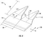
- FIGS. 3 , 6 , and 8 illustrate perspective views of various embodiments of the noise reducer 110 having a plurality of serrations 112 according to the present disclosure.
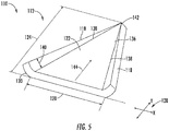
- FIGS. 4 , 5 , and 7 illustrate perspective views of various embodiments of the noise reducer 110 having a single serration 112 according to the present disclosure. It should be understood that each noise reducer 110 may include any number of serrations 112.
- the serration(s) 112 may each include a base portion 122 extending along a first plane 128.
- the first plane 128 of the base portion 122 may be defined by an X-Y plane relative to an X-Y coordinate system.
- the serration(s) 112 may define a length 124 relative to a Y-axis.
- the serrations(s) 112 may define a width 120 relative to an X-axis.
- the base portion 122 may have a generally triangular cross-section 136. It should be recognized that, in other embodiments, the base portion 122 may have any other suitable cross-sectional shape.
- the noise reducers 110 described herein may also include a base plate 114 that can be secured to the rotor blade 16. More specifically, in certain embodiments, the base plate 114 may be secured at the trailing edge 28 of the rotor blade 16. In such embodiments, the serration(s) 112 may extend from the base plate 114, e.g. and past or beyond the trailing edge 28. In addition, the serration(s) 112 may be integral with the base plate 114 and/or may be separately coupled to the base plate 114. In alternative embodiments, as shown in FIGS. 4 and 5 , the noise reducers 110 may be absent of a base plate 114.
- the serration(s) 112 may be mounted directly to the rotor blade 16.
- the base plate 114 and/or the serration(s) 12 of the noise reducer(s) 110 may be secured to the rotor blade 16 using any suitable means, such as by adhesives, tape, welding, and/or mechanical fasteners (e.g., bolts, screws, and rivets).
- the serration(s) 112 of the noise reducer(s) 110 described herein may include one or more side edge features 118 extending from the base portion 122.
- each serration 112 may include opposing side edge features 118 on opposing sides 138 of the base portion 122.
- the opposing side features 118 may be integral with the base portion 122.
- the opposing side edge features 118 may be separate features that are coupled to the base portion 122.
- the side edge feature(s) 118 may be coupled to the base portion 122 using any suitable means, such as by adhesives, tape, welding, and/or mechanical fasteners (e.g., bolts, screws, and rivets).
- the opposing side edge 118 features are configured to define a flow path (represented by arrow 144) therebetween.
- a flow path represented by arrow 1444
- vortices that are typically generated by edges of the serrations 112 may be reduced. Accordingly, the reduction of such vortices may decrease a noise profile of the wind turbine 10 while also increasing the efficiency of the rotor blade 16.
- the side edge feature(s) 118 may extend out of the first plane 128 defined by the base portion 122 so as to reduce the vortices generated by the serration(s) 112. More specifically, as shown in FIGS. 3 , 4 , and 6 , the side edge features 118 extend out of the first plane 128 of the base portion 122 at a predetermined angle 146.
- the predetermined angle 146 may be equal to or less than 90 degrees.
- the predetermined angle 146 may be from about 5 degrees to about 25 degrees.
- the side edge features 118 may be generally perpendicular to the first plane 128 of the base portion 122.
- the side edge feature(s) 118 are configured to provide an additional boundary between airflow leaving the pressure side 22 of the rotor blade 16 and suction side 24 of the rotor blade 16.
- the side edge feature(s) 118 are configured to impede the formation of vortices, reduce the size of such vortices, and/or decrease the intensity of the vortices that would otherwise form by flat edges of the serration(s) 112.
- the side edge feature(s) 118 may extend towards the suction side 24 of the rotor blade 16.
- the noise reducer(s) 110 may be attached to the rotor blade 16 such that the side edge feature(s) 118 faces toward the suction side 24 of the rotor blade 16.
- the side edge feature(s) 118 may extend toward the pressure side 22 of the rotor blade 16.
- the noise reducer(s) 110 may be attached to the rotor blade 16 such that the side edge feature(s) 118 faces toward the pressure side 22 of the rotor blade 16.
- one or more of the serrations 112 may include side edge features 118 that face the suction side 24 of the rotor blade 16 while other serrations 112 may include side edge features 118 that face the pressure side 22 of the rotor blade 16.
- the side edge features 118 may extend along a portion of the sides 138 of the base portion 122. In alternative embodiments, the side edge features 118 may extend along the entirety of the sides 138 of the base portion 122. In further embodiments, it should be understood that the side edge features 118 may be linear or may be curved. For example, FIGS. 3 , 4 , and 6 illustrate linear side edge features 118. Alternatively, as shown in FIG. 5 , the side edge features 118 may be curved. In such embodiments, as shown, the side edge features 118 may curve outward from the base portion 122 and into the first plane 128.
- the side edge features 118 of the serrations 112 may have a generally arcuate cross-section.
- the cross-section of the side edge features 118 are generally circular.
- the side edge features 118 may extend outward from the base portion 122 and/or the first plane 128.
- the side edge feature(s) 118 may be tapered.
- the side edge feature(s) 118 may define a thickness that tapers from a first end 130 of the serration(s) 112 to a second end 142 thereof.
- the slope of the taper of the side edge features 118 may be linear or may be non-linear.
- each of the serrations 112 has sides edges 118 that define a radius of curvature 132 configured to reduce vortices generated by the side edges 118 of the serration(s) 112.
- the side edges 118 define the flow path 144 that directs air therethrough so as to reduce vortices generated by the serration(s) 112.
- the radius of curvature 132 may vary based on the overall size of the serration(s) 112.
- the radius of curvature 132 may change along the length 124 of the serration(s) 112.
- the radius of curvature 132 may have a maximum value near the base plate 114 and transition to a smaller radius of curvature 132 along the length 124 and/or transition to a flat portion.
- the radius of curvature 132 may face the suction side 24 of the rotor blade 16.
- the noise reducer(s) 110 may be attached to the rotor blade 16 such that the radius of curvature 132 faces the suction side 24 of the rotor blade 16.
- the radius of curvature 132 may face the pressure side 22 of the rotor blade 16.
- the noise reducer(s) 110 may be attached to the rotor blade 16 such that radius of curvature 132 faces the pressure side 22 of the rotor blade 16.
- one or more of the serrations 112 may include radii of curvature 132 facing the suction side 24 of the rotor blade 16 while other serrations 112 includes radii of curvature 132 facing the pressure side 22 of the rotor blade 16.
Description
- The present disclosure relates generally to wind turbine rotor blades, and, more particularly, to noise reducers for wind turbine rotor blades having a serrated edge.
- Wind power is considered one of the cleanest, most environmentally friendly energy sources presently available, and wind turbines have gained increased attention in this regard. A modern wind turbine typically includes a tower, a generator, a gearbox, a nacelle, and a rotor. The rotor typically includes a rotatable hub having one or more rotor blades attached thereto. A pitch bearing is typically configured operably between the hub and the rotor blade to allow for rotation about a pitch axis. The rotor blades capture kinetic energy of wind using known airfoil principles. The rotor blades transmit the kinetic energy in the form of rotational energy so as to turn a shaft coupling the rotor blades to a gearbox, or if a gearbox is not used, directly to the generator. The generator then converts the mechanical energy to electrical energy that may be deployed to a utility grid.
- As the size of rotor blades increase, the noise produced by the rotor blades may also increase. As such, in certain instances, various blade add-on components may be attached to the rotor blades to assist with reducing noise generated thereby. More specifically, certain blade add-on components may be attached adjacent to the trailing edges of the rotor blades.
- In some instances, conventional noise reducers may generate noise-causing vortices. More specifically, a pressure differential from a pressure side of the noise reducer to a suction side of the noise reducer may create vortices at one or more boundaries of the noise reducer. For instance, for noise reducers having serrations, vortices may form at the edges of the serrations, which can generate noise.
- For example,
US 2015/0078910 A1 describes a wind turbine rotor blade and a noise reduction device. The noise reduction device includes a serrated extension for at least reducing noise generated from the wind turbine rotor blade, wherein the noise reduction device is attached to the trailing edge section. Other examples of prior art solutions are available in documents :US 2010/329879 A1 ,US 2016/177919 A1 ,US 2015/078896 A1 ,CN 105 822 511 A1 ,US 2016/052627 A1 andUS2017/107970 A1 . - Accordingly, the present disclosure is directed to noise reducers having at least one serration with an edge that minimizes the aforementioned noise-producing vortices.
- Aspects and advantages of the invention will be set forth in part in the following description, or may be obvious from the description, or may be learned through practice of the invention.
- The present disclosure is directed to a rotor blade assembly for a wind turbine according to the first alternative of
claim 1. The rotor blade assembly includes a rotor blade having surfaces defining a pressure side, a suction side, a leading edge, and a trailing edge extending between a blade tip and a blade root. The rotor blade assembly also includes at least one noise reducer secured at the trailing edge. The noise reducer(s) includes at least one serration having a base portion and at least one side edge feature extending from the base portion. Further, the base portion extends along a first plane. In addition, the side edge feature(s) extends out of the first plane so as to reduce vortices generated by the serration(s). - The base portion of the serration(s) has a triangular cross-section. In another embodiment, the noise reducer(s) may further include a base plate secured at the trailing edge. Further, the serration(s) may extend from the base plate. In such embodiments, the serrations(s) may be integral with the base plate. In alternative embodiments, the serration(s) may be coupled to the base plate.
- In one embodiment, the side edge feature(s) may extend toward at least one of the suction side or the pressure side of the rotor blade. According to the invention, the serration(s) has further include opposing side edge features on opposing sides of the base portion. In such embodiments, the opposing side edge features may be integral with the base portion. In alternative embodiments, the opposing side edge features may be separately coupled to the base portion.
- In further embodiments, the side edge feature(s) may extend at an angle out of the first plane of the base portion equal to or less than about 90 degrees. For example, in one embodiment, the side edge feature(s) may extend generally perpendicular out of the first plane of the base portion.
- In further embodiments, the side edge feature(s) may be tapered. In additional embodiments, the side edge feature(s) may be curved. In still further embodiments, the side edge feature(s) may have a generally arcuate cross-section.
- In another aspect, the present disclosure is directed to a rotor blade assembly for a wind turbine according to the second alternative of
claim 1. The rotor blade assembly includes a rotor blade having surfaces defining a pressure side, a suction side, a leading edge, and a trailing edge extending between a blade tip and a blade root. The rotor blade assembly also includes at least one noise reducer secured at the trailing edge. Further, the noise reducer(s) includes at least one serration having opposing side edges. In addition, the serration(s) has a radius of curvature defined between the opposing side edges that is configured to reduce vortices generated by the side edges of the serration(s). - In one embodiment, the radius of curvature may face at least one of the suction side or the pressure side of the rotor blade. It should be further understood that the rotor blade assembly may further include any of the additional features as described herein.
- These and other features, aspects and advantages of the present invention will become better understood with reference to the following description and appended claims. The accompanying drawings, which are incorporated in and constitute a part of this specification, illustrate the embodiments of the invention and, together with the description, serve to explain the principles of the invention.
- A full and enabling disclosure of the present invention, including the best mode thereof, directed to one of ordinary skill in the art, is set forth in the specification, which makes reference to the appended figures, in which:
-
FIG. 1 illustrates a perspective view of one embodiment of a wind turbine according to the present disclosure; -
FIG. 2 illustrates a perspective view a rotor blade assembly according to the present disclosure, particularly illustrating a plurality of noise reducers secured at the trailing edge of the rotor blade; -
FIG. 3 illustrates a perspective view of one embodiment of a noise reducer according to the present disclosure, particularly illustrating a noise reducer having a plurality of serrations that each include side edge features; -
FIG. 4 illustrates a perspective view of another embodiment of a noise reducer according to the present disclosure, particularly illustrating a noise reducer having a single serration that includes opposing, straight side edge features; -
FIG. 5 illustrates a perspective view of yet another embodiment of a noise reducer according to the present disclosure, particularly illustrating a noise reducer having a single serration that includes opposing, curved side edge features; -
FIG. 6 illustrates a perspective view of still another embodiment of a noise reducer according to the present disclosure, particularly illustrating a noise reducer having a plurality of serrations each including a base portion and opposing side edge features that are generally perpendicular to the base portion; -
FIG. 7 illustrates a perspective view of another embodiment of a noise reducer according to the present disclosure, particularly illustrating a noise reducer having a serration with opposing side edge features each having a generally arcuate cross-section; -
FIG. 8 illustrates a perspective view of a further embodiment of a noise reducer according to the present disclosure, particularly illustrating a noise reducer having a plurality of serrations each including a radius of curvature. - Reference now will be made in detail to embodiments of the invention, one or more examples of which are illustrated in the drawings. Each example is provided by way of explanation of the invention, not limitation of the invention. In fact, it will be apparent to those skilled in the art that various modifications can be made in the present invention without departing from the scope of the invention.
- Referring now to the drawings,
FIG. 1 illustrates a perspective view of one embodiment of awind turbine 10 according to the present disclosure. As shown, thewind turbine 10 includes atower 12 with anacelle 14 mounted thereon. A plurality ofrotor blades 16 are mounted to arotor hub 18, which is in turn connected to a main flange that turns a main rotor shaft. The wind turbine power generation and control components are housed within thenacelle 14. The view ofFIG. 1 is provided for illustrative purposes only to place the present invention in an exemplary field of use. It should be appreciated that the invention is not limited to any particular type of wind turbine configuration. - Referring now to
FIG. 2 , a perspective view of arotor blade assembly 100 including one of therotor blades 16 ofFIG. 1 is illustrated. As shown, therotor blade assembly 100 includes therotor blade 16. Further, therotor blade 16 generally includes surfaces defining apressure side 22 and asuction side 24 extending between aleading edge 26 and a trailingedge 28, and may extend from ablade tip 32 to ablade root 34. In one embodiment, therotor blade 16 may include a plurality of individual blade segments aligned in an end-to-end order from theblade tip 32 to theblade root 34. As such, each of the individual blade segments may be uniquely configured so that the plurality of blade segments defines acomplete rotor blade 16 having a designed aerodynamic profile, length, and other desired characteristics. For example, each of the blade segments may have an aerodynamic profile that corresponds to the aerodynamic profile of adjacent blade segments. Thus, the aerodynamic profiles of the blade segments may form a continuous aerodynamic profile of therotor blade 16. Alternatively, therotor blade 16 may be formed as a singular, unitary blade having the designed aerodynamic profile, length, and other desired characteristics. - In addition, the
rotor blade 16 may, in exemplary embodiments, be curved. Curving of therotor blade 16 may entail bending therotor blade 16 in a generally flapwise direction and/or in a generally edgewise direction. The flapwise direction may generally be construed as the direction (or the opposite direction) in which the aerodynamic lift acts on therotor blade 16. The edgewise direction is generally perpendicular to the flapwise direction. Flapwise curvature of therotor blade 16 is also known as pre-bend, while edgewise curvature is also known as sweep. Thus, acurved rotor blade 16 may be pre-bent and/or swept. Curving may enable therotor blade 16 to better withstand flapwise and edgewise loads during operation of thewind turbine 10, and may further provide clearance for therotor blade 16 from thetower 12 during operation of thewind turbine 10. - Still referring to
FIG. 2 , therotor blade 16 may further define apitch axis 40. Thepitch axis 40 may generally be defined with respect to therotor hub 18 of thewind turbine 10. For example, thepitch axis 40 may extend generally perpendicularly to therotor hub 18 and theblade root 34 through the center of theblade root 34. A pitch angle or blade pitch of therotor blade 16, i.e., an angle that determines a perspective of therotor blade 16 with respect to the airflow past thewind turbine 10, may be defined by rotation of therotor blade 16 about thepitch axis 40. Therotor blade 16 may further define achord 42 and aspan 44. As shown inFIGS. 2 , thechord 42 may vary throughout thespan 44 of therotor blade 16. Thus, alocal chord 46 may be defined for therotor blade 16 at any point on therotor blade 16 along thespan 44. - In addition, as shown, the
rotor blade assembly 100 includes at least onenoise reducer 110, e.g. secured at or near the trailingedge 28. Alternatively, thenoise reducer 110 may be secured at or near adjacent the leadingedge 26 of therotor blade 16, adjacent to theblade tip 32, and/or adjacent to theblade root 34 of therotor blade 16. Thus, it should be understood that thenoise reducer 110 may be secured at any suitable location along any of the surfaces of therotor blade 16. As such, thenoise reducer 110 is configured to reduce noise generated by therotor blades 16 during operation of thewind turbine 10 and/or may increase the efficiency of therotor blades 16. Thenoise reducer 110 may be secured to therotor blade 16 using any suitable means, such as by adhesives, tape, welding, and/or mechanical fasteners (e.g., bolts, screws, and rivets). - Further, as shown, the noise reducer(s) 110 may extend along a portion of the trailing
edge 28 of therotor blade 16. For example, the noise reducer(s) 110 may extend along a portion of the trailingedge 28 near theblade tip 32, as shown inFIG. 2 . In other embodiments, the noise reducer(s) 110 may extend along a portion of the trailingedge 28 near theblade root 34. Still, in other embodiments, the noise reducer(s) 110 may extend along a portion of therotor blade 16 in between theblade tip 32 and theblade root 34. It should also be recognized that the noise reducer(s) 110 may extend along the entirety of the trailingedge 28. - Referring now to
FIGS. 3-8 , multiple perspective views of various embodiments of thenoise reducers 110 according to the present disclosure are illustrated. More particularly, as shown, thenoise reducers 110 of the present disclosure each include at least oneserration 112. For example,FIGS. 3 ,6 , and8 illustrate perspective views of various embodiments of thenoise reducer 110 having a plurality ofserrations 112 according to the present disclosure.FIGS. 4 ,5 , and7 illustrate perspective views of various embodiments of thenoise reducer 110 having asingle serration 112 according to the present disclosure. It should be understood that eachnoise reducer 110 may include any number ofserrations 112. - Moreover, as shown in
FIGS. 3-7 , the serration(s) 112 may each include abase portion 122 extending along afirst plane 128. For example, as shown inFIG. 3 , thefirst plane 128 of thebase portion 122 may be defined by an X-Y plane relative to an X-Y coordinate system. Thus, as shown, the serration(s) 112 may define alength 124 relative to a Y-axis. Further, as shown, the serrations(s) 112 may define awidth 120 relative to an X-axis. In addition, as shown, thebase portion 122 may have a generallytriangular cross-section 136. It should be recognized that, in other embodiments, thebase portion 122 may have any other suitable cross-sectional shape. - In addition, as shown in
FIGS. 3 and6-8 , thenoise reducers 110 described herein may also include abase plate 114 that can be secured to therotor blade 16. More specifically, in certain embodiments, thebase plate 114 may be secured at the trailingedge 28 of therotor blade 16. In such embodiments, the serration(s) 112 may extend from thebase plate 114, e.g. and past or beyond the trailingedge 28. In addition, the serration(s) 112 may be integral with thebase plate 114 and/or may be separately coupled to thebase plate 114. In alternative embodiments, as shown inFIGS. 4 and5 , thenoise reducers 110 may be absent of abase plate 114. In such embodiments, the serration(s) 112 may be mounted directly to therotor blade 16. As such, thebase plate 114 and/or the serration(s) 12 of the noise reducer(s) 110 may be secured to therotor blade 16 using any suitable means, such as by adhesives, tape, welding, and/or mechanical fasteners (e.g., bolts, screws, and rivets). - Referring particularly to
FIGS. 3-7 , the serration(s) 112 of the noise reducer(s) 110 described herein may include one or more side edge features 118 extending from thebase portion 122. For example, as shown, eachserration 112 may include opposing side edge features 118 on opposingsides 138 of thebase portion 122. In one embodiment, the opposing side features 118 may be integral with thebase portion 122. Alternatively, the opposing side edge features 118 may be separate features that are coupled to thebase portion 122. For example, the side edge feature(s) 118 may be coupled to thebase portion 122 using any suitable means, such as by adhesives, tape, welding, and/or mechanical fasteners (e.g., bolts, screws, and rivets). As such, the opposingside edge 118 features are configured to define a flow path (represented by arrow 144) therebetween. Thus, vortices that are typically generated by edges of theserrations 112 may be reduced. Accordingly, the reduction of such vortices may decrease a noise profile of thewind turbine 10 while also increasing the efficiency of therotor blade 16. - Referring still to
FIGS. 3-7 , the side edge feature(s) 118 may extend out of thefirst plane 128 defined by thebase portion 122 so as to reduce the vortices generated by the serration(s) 112. More specifically, as shown inFIGS. 3 ,4 , and6 , the side edge features 118 extend out of thefirst plane 128 of thebase portion 122 at apredetermined angle 146. For example, in one embodiment, thepredetermined angle 146 may be equal to or less than 90 degrees. For instance, in certain embodiments, thepredetermined angle 146 may be from about 5 degrees to about 25 degrees. - As shown particularly in
FIG. 6 , the side edge features 118 may be generally perpendicular to thefirst plane 128 of thebase portion 122. Thus, the side edge feature(s) 118 are configured to provide an additional boundary between airflow leaving thepressure side 22 of therotor blade 16 andsuction side 24 of therotor blade 16. As such, the side edge feature(s) 118 are configured to impede the formation of vortices, reduce the size of such vortices, and/or decrease the intensity of the vortices that would otherwise form by flat edges of the serration(s) 112. - In certain embodiments, the side edge feature(s) 118 may extend towards the
suction side 24 of therotor blade 16. For example, the noise reducer(s) 110 may be attached to therotor blade 16 such that the side edge feature(s) 118 faces toward thesuction side 24 of therotor blade 16. In other embodiments, the side edge feature(s) 118 may extend toward thepressure side 22 of therotor blade 16. For example, the noise reducer(s) 110 may be attached to therotor blade 16 such that the side edge feature(s) 118 faces toward thepressure side 22 of therotor blade 16. Still, in further embodiments, one or more of theserrations 112 may include side edge features 118 that face thesuction side 24 of therotor blade 16 whileother serrations 112 may include side edge features 118 that face thepressure side 22 of therotor blade 16. - In additional embodiments, as shown in
FIG. 6 , the side edge features 118 may extend along a portion of thesides 138 of thebase portion 122. In alternative embodiments, the side edge features 118 may extend along the entirety of thesides 138 of thebase portion 122. In further embodiments, it should be understood that the side edge features 118 may be linear or may be curved. For example,FIGS. 3 ,4 , and6 illustrate linear side edge features 118. Alternatively, as shown inFIG. 5 , the side edge features 118 may be curved. In such embodiments, as shown, the side edge features 118 may curve outward from thebase portion 122 and into thefirst plane 128. - In other embodiments, as shown in
FIGS. 7 , the side edge features 118 of theserrations 112 may have a generally arcuate cross-section. For example, as shown, the cross-section of the side edge features 118 are generally circular. In such embodiments, the side edge features 118 may extend outward from thebase portion 122 and/or thefirst plane 128. - In addition, as shown in
FIGS. 3-7 , the side edge feature(s) 118 may be tapered. For example, as shown, the side edge feature(s) 118 may define a thickness that tapers from afirst end 130 of the serration(s) 112 to asecond end 142 thereof. In certain embodiments, the slope of the taper of the side edge features 118 may be linear or may be non-linear. - Referring now to
FIG. 8 , a perspective view of another embodiment of thenoise reducer 110 having a plurality ofserrations 112 according to the present disclosure is illustrated. More specifically, as shown, each of theserrations 112 has sides edges 118 that define a radius ofcurvature 132 configured to reduce vortices generated by the side edges 118 of the serration(s) 112. Thus, as shown, the side edges 118 define theflow path 144 that directs air therethrough so as to reduce vortices generated by the serration(s) 112. It should be recognized that the radius ofcurvature 132 may vary based on the overall size of the serration(s) 112. In certain embodiment, the radius ofcurvature 132 may change along thelength 124 of the serration(s) 112. For example, the radius ofcurvature 132 may have a maximum value near thebase plate 114 and transition to a smaller radius ofcurvature 132 along thelength 124 and/or transition to a flat portion. - In certain embodiments, the radius of
curvature 132 may face thesuction side 24 of therotor blade 16. For example, the noise reducer(s) 110 may be attached to therotor blade 16 such that the radius ofcurvature 132 faces thesuction side 24 of therotor blade 16. In another embodiment, the radius ofcurvature 132 may face thepressure side 22 of therotor blade 16. For example, the noise reducer(s) 110 may be attached to therotor blade 16 such that radius ofcurvature 132 faces thepressure side 22 of therotor blade 16. Still, in further embodiments, one or more of theserrations 112 may include radii ofcurvature 132 facing thesuction side 24 of therotor blade 16 whileother serrations 112 includes radii ofcurvature 132 facing thepressure side 22 of therotor blade 16. - The scope of the claimed invention is defined by the appended claims.
Claims (12)
- A rotor blade assembly for a wind turbine (10), the rotor blade assembly comprising:a rotor blade (100) having surfaces defining a pressure side (22), a suction side (24), a leading edge (26), and a trailing edge (28) extending between a blade tip (32) and a blade root (34); and,at least one noise reducer (110) secured at the trailing edge (28), the noise reducer (110) comprising at least one serration (112),the at least one serration (112) comprising abase portion (122) having a triangular cross-section (136) and extending along a first plane (128) defined by an X-Y plane relative to an X-Y coordinate, andopposing side edge features (118) extending from the base portion (122) on opposing sides (138) of the base portion (122), having an arcuate form cross-section, and extending out of the first plane (128) so as to reduce vortices generated by the serration (112), orwherein the at least one serration (112) comprisesa generally triangular cross-section,opposing side edges (118) and a radius of curvature (132) defined between the opposing side edges (118), wherein the radius of curvature (132) is configured to reduce vortices generated by the side edges of the serration (112).
- The rotor blade assembly of claim 1, wherein the opposing side edge features (118) have a circular cross-section.
- The rotor blade assembly of claim 1 or 2, wherein the opposing side edge features (118) are integral with the base portion (122).
- The rotor blade assembly of claim 1 or 2, wherein the opposing side edge features (118) are separately coupled to the base portion (122).
- The rotor blade assembly of any of the preceding claims, wherein the at least one side edge feature (118) extends toward at least one of the suction side (24) or the pressure side (22) of the rotor blade.
- The rotor blade assembly of any of the preceding claims, wherein the at least one side edge feature (118) extends at an angle out of the first plane (128) of the base portion (122) equal to or less than about 90 degrees.
- The rotor blade assembly of claim 6, wherein the at least one side edge feature (118) extends generally perpendicular out of the first plane (128) of the base portion (122).
- The rotor blade assembly of any of the preceding claims, wherein the at least one side edge feature (118) is tapered.
- The rotor blade assembly of any of the preceding claims, wherein the noise reducer (112) further comprises a base plate (114) secured at the trailing edge (28), the at least one serration (112) extending from the base plate (114).
- The rotor blade assembly of claim 9, wherein the at least one serration (112) is integral with the base plate (114), or wherein the at least one serration (112) is coupled to the base plate (114).
- The rotor blade assembly of any of the claims 1 or 10, wherein the radius of curvature (132) faces at least one of the suction side (24) or the pressure side (24) of the rotor blade.
- A wind turbine (10) comprising: a tower (12), a nacelle (14) mounted to the tower (12), and a plurality of rotor blades assemblies (100) according to claim 1 mounted to a rotor hub (18).
Applications Claiming Priority (1)
| Application Number | Priority Date | Filing Date | Title |
|---|---|---|---|
| US15/952,498 US10767623B2 (en) | 2018-04-13 | 2018-04-13 | Serrated noise reducer for a wind turbine rotor blade |
Publications (2)
| Publication Number | Publication Date |
|---|---|
| EP3553307A1 EP3553307A1 (en) | 2019-10-16 |
| EP3553307B1 true EP3553307B1 (en) | 2021-09-01 |
Family
ID=66182439
Family Applications (1)
| Application Number | Title | Priority Date | Filing Date |
|---|---|---|---|
| EP19169287.0A Active EP3553307B1 (en) | 2018-04-13 | 2019-04-15 | Serrated noise reducer for a wind turbine rotor blade |
Country Status (2)
| Country | Link |
|---|---|
| US (1) | US10767623B2 (en) |
| EP (1) | EP3553307B1 (en) |
Families Citing this family (2)
| Publication number | Priority date | Publication date | Assignee | Title |
|---|---|---|---|---|
| GB202002557D0 (en) * | 2020-02-24 | 2020-04-08 | Kudhail Jagjeet Singh | Noise reduction element and a wind turbine blade comprising a noise reduction element |
| TWI775377B (en) * | 2021-04-06 | 2022-08-21 | 宏碁股份有限公司 | Cooling fan |
Citations (3)
| Publication number | Priority date | Publication date | Assignee | Title |
|---|---|---|---|---|
| US20150078910A1 (en) * | 2013-09-18 | 2015-03-19 | Siemens Aktiengesellschaft | Arrangement to reduce noise of a wind turbine rotor blade |
| US20160052627A1 (en) * | 2014-08-19 | 2016-02-25 | The Boeing Company | Noise Reducing Profile For Helicopter Rotor Blade Tracking Wedges |
| US20170107970A1 (en) * | 2014-07-03 | 2017-04-20 | LW WP Patent Holding A/S | A Wind Turbine Blade |
Family Cites Families (124)
| Publication number | Priority date | Publication date | Assignee | Title |
|---|---|---|---|---|
| US573562A (en) | 1896-12-22 | Propeller | ||
| US175355A (en) | 1876-03-28 | Waltee king | ||
| US2899125A (en) | 1959-08-11 | Chausson | ||
| USRE19412E (en) | 1935-01-01 | Aircraft and control thereof | ||
| US1861065A (en) | 1930-08-18 | 1932-05-31 | Poot Philippe | Screw-propeller for flying machines and other aerodynamics apparatus |
| US2071012A (en) | 1932-11-22 | 1937-02-16 | Adams Herbert Luther | Noiseless device |
| US2238749A (en) | 1939-01-30 | 1941-04-15 | Clarence B Swift | Fan blade |
| US2225312A (en) | 1939-10-05 | 1940-12-17 | Bell Telephone Labor Inc | Acoustic device |
| US2312219A (en) | 1941-04-21 | 1943-02-23 | Sensenich Brothers | Aircraft propeller |
| US2469167A (en) | 1946-06-11 | 1949-05-03 | American Steel & Wire Co | Vibration damper |
| IT1036993B (en) | 1974-07-02 | 1979-10-30 | Rotron Inc | DEVICE FOR THE MOVEMENT OF A FLUID |
| US4204629A (en) | 1977-07-20 | 1980-05-27 | Rolls-Royce Limited | Brush seal and a method of manufacture |
| US4618313A (en) | 1980-02-06 | 1986-10-21 | Cofimco S.R.L. | Axial propeller with increased effective displacement of air whose blades are not twisted |
| GB8626408D0 (en) | 1986-11-05 | 1987-12-16 | Secr Defence | Damping treatment for pipes & bodies |
| US4720244A (en) | 1987-05-21 | 1988-01-19 | Hudson Products Corporation | Fan blade for an axial flow fan and method of forming same |
| US5088665A (en) * | 1989-10-31 | 1992-02-18 | The United States Of America As Represented By The Administrator Of The National Aeronautics And Space Administration | Serrated trailing edges for improving lift and drag characteristics of lifting surfaces |
| US5320491A (en) | 1992-07-09 | 1994-06-14 | Northern Power Systems, Inc. | Wind turbine rotor aileron |
| US5328329A (en) | 1993-07-06 | 1994-07-12 | Hudson Products Corporation | Fan blade width extender |
| NL9301910A (en) | 1993-11-04 | 1995-06-01 | Stork Prod Eng | Wind turbine. |
| US5522266A (en) | 1993-11-30 | 1996-06-04 | Medex, Inc. | Low cost pressure transducer particularly for medical applications |
| CA2141529A1 (en) | 1994-10-25 | 1996-04-26 | Frances Gould | Street sweeper brush assembly |
| DE4440744A1 (en) | 1994-11-15 | 1996-05-23 | Peter Frieden | Wind turbine generator rotor blade |
| US6352601B1 (en) | 1994-12-27 | 2002-03-05 | The B. F. Goodrich Company | Self-adhering ice protector |
| DE19647102A1 (en) | 1996-11-14 | 1998-05-20 | Philippe Arribi | Flow body |
| US6023898A (en) | 1998-06-01 | 2000-02-15 | Ground Star, Llc | Metal frame building construction |
| JP2000120524A (en) | 1998-10-16 | 2000-04-25 | Mitsubishi Heavy Ind Ltd | Windmill blade |
| EE200100306A (en) | 1998-12-09 | 2002-08-15 | Wobben Aloys | Wind turbine rotor blade |
| GB2358130A (en) | 2000-01-17 | 2001-07-18 | Llewellyn Jones John Adrian | One-piece toothbrush |
| DE10020177A1 (en) | 2000-04-25 | 2001-11-08 | Daimler Chrysler Ag | Device for reducing noise on aircraft wings |
| BR0003706A (en) | 2000-05-30 | 2002-02-13 | Tecsis Tecnologia E Sist S Ava | Axle fan for low noise and high efficiency |
| US6733240B2 (en) | 2001-07-18 | 2004-05-11 | General Electric Company | Serrated fan blade |
| CN1975152B (en) | 2001-07-19 | 2012-03-21 | 维斯塔斯风力系统集团公司 | Wind turbine blade |
| DE10157849A1 (en) | 2001-11-24 | 2003-06-12 | Airbus Gmbh | Arrangement for reducing the aerodynamic noise on a slat of a commercial aircraft |
| US6872048B2 (en) | 2001-11-26 | 2005-03-29 | Lennox Industries, Inc. | Fan with reduced noise generation |
| US7059833B2 (en) | 2001-11-26 | 2006-06-13 | Bonus Energy A/S | Method for improvement of the efficiency of a wind turbine rotor |
| EP1338793A3 (en) | 2002-02-22 | 2010-09-01 | Mitsubishi Heavy Industries, Ltd. | Serrated wind turbine blade trailing edge |
| JP2003254225A (en) | 2002-03-05 | 2003-09-10 | Ebara Corp | Device for reducing airflow noise of windmill |
| CN100455793C (en) | 2003-03-31 | 2009-01-28 | 丹麦技术大学 | Control of power, loads and/or stability of a horizontal axis wind turbine by use of variable blade geometry control |
| US20040219059A1 (en) | 2003-05-03 | 2004-11-04 | Novosci Corp. | Heart bypass system incorporating minimized extracorporeal blood circulation system and related method of use |
| DE102004008618A1 (en) | 2004-02-21 | 2005-09-08 | Geka Brush Gmbh | Brush for applying cosmetic or nourishing products |
| EP1607624A3 (en) | 2004-06-15 | 2008-11-26 | NORDEX ENERGY GmbH | Turbine blade for a wind turbine |
| DE102005019905B4 (en) | 2005-04-29 | 2012-12-06 | Nordex Energy Gmbh | Rotor blade for a wind energy plant |
| US7328770B2 (en) | 2005-06-16 | 2008-02-12 | Owens Jeffrey A | Strap silencer |
| US7637721B2 (en) | 2005-07-29 | 2009-12-29 | General Electric Company | Methods and apparatus for producing wind energy with reduced wind turbine noise |
| CA2620880A1 (en) | 2005-08-22 | 2007-04-19 | Viryd Technologies Inc. | Fluid energy converter |
| ES2318925B1 (en) | 2005-09-22 | 2010-02-11 | GAMESA INNOVATION & TECHNOLOGY, S.L. | AEROGENERATOR WITH A BLADE ROTOR THAT REDUCES NOISE. |
| US7458777B2 (en) | 2005-09-22 | 2008-12-02 | General Electric Company | Wind turbine rotor assembly and blade having acoustic flap |
| US20070125919A1 (en) | 2005-12-06 | 2007-06-07 | Hopkins William K | Apparatus and method for displaying objects on shelves and the like |
| DK176352B1 (en) | 2005-12-20 | 2007-09-10 | Lm Glasfiber As | Profile series for blade for wind turbines |
| NL1031223C1 (en) | 2006-02-23 | 2007-08-24 | Stichting Nationaal Lucht En R | Wind turbine blade, has brush at back edge of blade, where brush includes synthetic bristles that rest parallel to top or bottom of blade |
| US7740206B2 (en) | 2006-04-13 | 2010-06-22 | The Board Of Trustees Of The Leland Stanford Junior University | Translating active Gurney flap to alleviate aircraft wake vortex hazard |
| DE102006017897B4 (en) | 2006-04-13 | 2008-03-13 | Repower Systems Ag | Rotor blade of a wind turbine |
| BE1017134A5 (en) | 2006-05-11 | 2008-03-04 | Delaere Marc | BRUSH FOR A SCRUB, SWEEP AND / OR BONE MACHINE AND SPRAY DEVICE FOR CLEANING MULTIPLE SURFACES SIZED BY GROOPS AND / OR JOINING EACH OTHER. |
| EP2027390B2 (en) | 2006-06-09 | 2020-07-01 | Vestas Wind Systems A/S | A wind turbine blade and a pitch controlled wind turbine |
| US20080001363A1 (en) | 2006-06-28 | 2008-01-03 | General Electric Company | Brush sealing system and method for rotary machines |
| EP1892442A1 (en) | 2006-08-18 | 2008-02-27 | Siemens Aktiengesellschaft | Brush seal for a turbomachine |
| US10611468B2 (en) | 2006-09-08 | 2020-04-07 | Steven Sullivan | Method and apparatus for mitigating trailing vortex wakes of lifting or thrust generating bodies |
| DE102006043462A1 (en) | 2006-09-15 | 2008-03-27 | Deutsches Zentrum für Luft- und Raumfahrt e.V. | Aerodynamic component e.g. rotor blade, for use in wind turbine, has pair of surface units on high pressure side engaged between two surface units on low pressure side in main extension direction of trailing edge |
| US7959412B2 (en) | 2006-09-29 | 2011-06-14 | General Electric Company | Wind turbine rotor blade with acoustic lining |
| US7811063B2 (en) | 2006-11-03 | 2010-10-12 | General Electric Company | Damping element for a wind turbine rotor blade |
| JP2008115783A (en) | 2006-11-06 | 2008-05-22 | Fuji Heavy Ind Ltd | Blade for wind turbine |
| EP1927454A1 (en) | 2006-11-29 | 2008-06-04 | Trisa Holding AG | Toothbrush with partially coated surface |
| US20080166241A1 (en) | 2007-01-04 | 2008-07-10 | Stefan Herr | Wind turbine blade brush |
| US7918653B2 (en) | 2007-02-07 | 2011-04-05 | General Electric Company | Rotor blade trailing edge assemby and method of use |
| US7413408B1 (en) | 2007-02-22 | 2008-08-19 | Samuel B Tafoya | Vibration-reducing and noise-reducing spoiler for helicopter rotors, aircraft wings, propellers, and turbine blades |
| WO2008113349A2 (en) | 2007-03-20 | 2008-09-25 | Vestas Wind Systems A/S | Slow rotating wind turbine rotor with slender blades |
| WO2008131800A1 (en) | 2007-04-30 | 2008-11-06 | Vestas Wind Systems A/S | A wind turbine blade |
| US7901189B2 (en) | 2007-05-14 | 2011-03-08 | General Electric Company | Wind-turbine blade and method for reducing noise in wind turbine |
| ES2345583B1 (en) | 2007-05-31 | 2011-07-28 | GAMESA INNOVATION & TECHNOLOGY, S.L. | AEROGENERATOR SHOVEL WITH ANTI-NOISE DEVICES. |
| US7927078B2 (en) | 2007-07-12 | 2011-04-19 | General Electric Company | Wind turbine blade tip vortex breakers |
| NL2000821C2 (en) | 2007-08-17 | 2009-02-18 | Stichting Energie | Wind turbine and rotor blade. |
| CA2696773A1 (en) | 2007-08-23 | 2009-02-26 | Invacare Corporation | Method and apparatus for adjusting desired pressure in positive airway pressure devices |
| US20090074585A1 (en) | 2007-09-19 | 2009-03-19 | General Electric Company | Wind turbine blades with trailing edge serrations |
| US8047804B2 (en) | 2007-12-27 | 2011-11-01 | General Electric Company | Wind tower and method of assembling the same |
| US20090097976A1 (en) | 2007-10-15 | 2009-04-16 | General Electric Company | Active damping of wind turbine blades |
| DK2053240T3 (en) | 2007-10-22 | 2011-07-11 | Actiflow B V | Wind turbine with boundary layer control |
| US8418967B2 (en) | 2008-02-21 | 2013-04-16 | Cornerstone Research Group, Inc. | Passive adaptive structures |
| GB2462308A (en) | 2008-08-01 | 2010-02-03 | Vestas Wind Sys As | Extension portion for wind turbine blade |
| EP2309119A1 (en) | 2008-08-06 | 2011-04-13 | Mitsubishi Heavy Industries, Ltd. | Windmill blade and wind power generator using same |
| US9239039B2 (en) | 2008-10-27 | 2016-01-19 | General Electric Company | Active circulation control of aerodynamic structures |
| EP2138714A1 (en) | 2008-12-12 | 2009-12-30 | Lm Glasfiber A/S | Wind turbine blade having a flow guiding device with optimised height |
| US20100143151A1 (en) | 2009-02-06 | 2010-06-10 | General Electric Company | Permeable acoustic flap for wind turbine blades |
| EP2253838A1 (en) | 2009-05-18 | 2010-11-24 | Lm Glasfiber A/S | A method of operating a wind turbine |
| EP2438299A2 (en) | 2009-06-03 | 2012-04-11 | Flodesign Wind Turbine Corporation | Wind turbine blades with mixer lobes |
| EP2270312A1 (en) | 2009-07-01 | 2011-01-05 | PEM-Energy Oy | Aero- or hydrodynamic construction |
| RU2539123C2 (en) | 2009-08-06 | 2015-01-10 | Мет Тек Инк. | Non-magnetic azimuth measurement using met of electrochemical sensors |
| US7909576B1 (en) | 2010-06-24 | 2011-03-22 | General Electric Company | Fastening device for rotor blade component |
| US8083488B2 (en) | 2010-08-23 | 2011-12-27 | General Electric Company | Blade extension for rotor blade in wind turbine |
| US8038407B2 (en) | 2010-09-14 | 2011-10-18 | General Electric Company | Wind turbine blade with improved trailing edge bond |
| US7976276B2 (en) | 2010-11-04 | 2011-07-12 | General Electric Company | Noise reducer for rotor blade in wind turbine |
| US7976283B2 (en) | 2010-11-10 | 2011-07-12 | General Electric Company | Noise reducer for rotor blade in wind turbine |
| US8523515B2 (en) | 2010-11-15 | 2013-09-03 | General Electric Company | Noise reducer for rotor blade in wind turbine |
| EP2646682A4 (en) | 2010-11-30 | 2014-08-06 | Gen Electric | Noise reducer for rotor blade in wind turbine |
| US8267657B2 (en) | 2010-12-16 | 2012-09-18 | General Electric Company | Noise reducer for rotor blade in wind turbine |
| US20110268558A1 (en) | 2010-12-20 | 2011-11-03 | General Electric Company | Noise reducer for rotor blade in wind turbine |
| US8414261B2 (en) | 2011-05-31 | 2013-04-09 | General Electric Company | Noise reducer for rotor blade in wind turbine |
| US8834127B2 (en) | 2011-09-09 | 2014-09-16 | General Electric Company | Extension for rotor blade in wind turbine |
| WO2013045601A1 (en) | 2011-09-29 | 2013-04-04 | Lm Wind Power A/S | A wind turbine blade |
| US8506250B2 (en) | 2011-10-19 | 2013-08-13 | General Electric Company | Wind turbine rotor blade with trailing edge extension and method of attachment |
| ES2621483T3 (en) | 2011-11-23 | 2017-07-04 | Lm Wp Patent Holding A/S | Wind turbine blade |
| US9341158B2 (en) | 2011-12-08 | 2016-05-17 | Inventus Holdings, Llc | Quiet wind turbine blade |
| US8430638B2 (en) | 2011-12-19 | 2013-04-30 | General Electric Company | Noise reducer for rotor blade in wind turbine |
| US20130164141A1 (en) | 2011-12-22 | 2013-06-27 | General Electric Company | Blade with semi-rigid trailing edge |
| US20130280085A1 (en) | 2012-04-23 | 2013-10-24 | General Electric Company | Flow modification device for rotor blade in wind turbine |
| WO2014044412A1 (en) | 2012-09-24 | 2014-03-27 | Siemens Aktiengesellschaft | A wind turbine blade with a noise reducing device |
| EP2867524A1 (en) * | 2012-09-24 | 2015-05-06 | Siemens Aktiengesellschaft | A wind turbine blade |
| WO2014048437A1 (en) | 2012-09-25 | 2014-04-03 | Vestas Wind Systems A/S | Noise attenuator for a wind turbine blade and a method for reducing wind turbine noise |
| US20140093380A1 (en) | 2012-10-03 | 2014-04-03 | General Electric Company | Noise reduction tab and method for wind turbine rotor blade |
| US9677537B2 (en) | 2013-03-28 | 2017-06-13 | General Electric Company | Acoustic shield for noise reduction in wind turbines |
| US20150050154A1 (en) | 2013-05-23 | 2015-02-19 | Kristian R. DIXON | Airfoil trailing edge apparatus for noise reduction |
| DK177928B1 (en) * | 2013-06-17 | 2015-01-19 | Envision Energy Denmark Aps | Wind turbine blade with extended shell section |
| NL2011236C2 (en) * | 2013-07-30 | 2015-02-02 | Stichting Energie | Rotor blade for a wind turbine, and wind turbine field. |
| DK2851555T3 (en) | 2013-09-18 | 2018-05-22 | Siemens Ag | Wind turbine rotor blade with thanks to extension |
| EP2851554A1 (en) | 2013-09-18 | 2015-03-25 | Siemens Aktiengesellschaft | Arrangement to reduce noise emission |
| US9494134B2 (en) | 2013-11-20 | 2016-11-15 | General Electric Company | Noise reducing extension plate for rotor blade in wind turbine |
| DK177907B1 (en) | 2013-11-21 | 2014-12-15 | Envision Energy Denmark Aps | Wind turbine blade with wave shaped trailing edge |
| US9670901B2 (en) * | 2014-03-21 | 2017-06-06 | Siemens Aktiengesellschaft | Trailing edge modifications for wind turbine airfoil |
| US20160177922A1 (en) | 2014-12-22 | 2016-06-23 | Siemens Aktiengesellschaft | Trailing edge jets on wind turbine blade for noise reduction |
| EP3037655A1 (en) * | 2014-12-22 | 2016-06-29 | Siemens Aktiengesellschaft | Rotor blade extension |
| ES2864028T3 (en) | 2015-05-21 | 2021-10-13 | Siemens Gamesa Renewable Energy As | Toothed rotor blade for wind turbine |
| US10240576B2 (en) | 2015-11-25 | 2019-03-26 | General Electric Company | Wind turbine noise reduction with acoustically absorbent serrations |
| CN105822511B (en) | 2016-05-16 | 2018-06-19 | 宜春学院 | A kind of method and apparatus for installing vortex generator or similar flow control apparatus |
| EP3267031B1 (en) | 2016-07-05 | 2019-06-12 | Siemens Gamesa Renewable Energy A/S | Wind turbine rotor blade with vortex generators |
| CN106168193B (en) | 2016-08-26 | 2018-12-21 | 明阳智慧能源集团股份公司 | A kind of denoising structure of blade of wind-driven generator |
-
2018
- 2018-04-13 US US15/952,498 patent/US10767623B2/en active Active
-
2019
- 2019-04-15 EP EP19169287.0A patent/EP3553307B1/en active Active
Patent Citations (3)
| Publication number | Priority date | Publication date | Assignee | Title |
|---|---|---|---|---|
| US20150078910A1 (en) * | 2013-09-18 | 2015-03-19 | Siemens Aktiengesellschaft | Arrangement to reduce noise of a wind turbine rotor blade |
| US20170107970A1 (en) * | 2014-07-03 | 2017-04-20 | LW WP Patent Holding A/S | A Wind Turbine Blade |
| US20160052627A1 (en) * | 2014-08-19 | 2016-02-25 | The Boeing Company | Noise Reducing Profile For Helicopter Rotor Blade Tracking Wedges |
Also Published As
| Publication number | Publication date |
|---|---|
| US10767623B2 (en) | 2020-09-08 |
| EP3553307A1 (en) | 2019-10-16 |
| US20190316565A1 (en) | 2019-10-17 |
Similar Documents
| Publication | Publication Date | Title |
|---|---|---|
| US8523515B2 (en) | Noise reducer for rotor blade in wind turbine | |
| US7976276B2 (en) | Noise reducer for rotor blade in wind turbine | |
| EP2799710B1 (en) | Rotor blade assembly having vortex generators for wind turbine | |
| EP2712399B1 (en) | Wind turbine blade with noise reduction devices and related method | |
| DK178555B1 (en) | Wind turbine rotor blade | |
| EP3844386B1 (en) | Noise reducer for a wind turbine rotor blade having a cambered serration | |
| US10047719B2 (en) | Winglet for a wind turbine rotor blade | |
| US20120027588A1 (en) | Root flap for rotor blade in wind turbine | |
| EP2657513A2 (en) | Flow modification device for rotor blade in wind turbine | |
| EP2141355A2 (en) | Wind turbine blades with multiple curvatures | |
| AU2013231165B2 (en) | Noise reduction tab and method for wind turbine rotor blade | |
| US20120217754A1 (en) | Wind turbine blade, wind turbine generator with the same, and design method of wind turbine blade | |
| EP3553307B1 (en) | Serrated noise reducer for a wind turbine rotor blade | |
| EP3853470B1 (en) | Wind turbine rotor blade assembly for reduced noise | |
| EP3472456B1 (en) | Wind turbine blade with tip end serrations | |
| EP2682597A1 (en) | Wind turbine blade, wind-powered electricity generator provided with same, and method for designing wind turbine blade | |
| US20200063709A1 (en) | Rotor Blade Assembly Having Twist, Chord, and Thickness Distribution for Improved Performance | |
| US11781522B2 (en) | Wind turbine rotor blade assembly for reduced noise |
Legal Events
| Date | Code | Title | Description |
|---|---|---|---|
| PUAI | Public reference made under article 153(3) epc to a published international application that has entered the european phase |
Free format text: ORIGINAL CODE: 0009012 |
|
| STAA | Information on the status of an ep patent application or granted ep patent |
Free format text: STATUS: THE APPLICATION HAS BEEN PUBLISHED |
|
| AK | Designated contracting states |
Kind code of ref document: A1 Designated state(s): AL AT BE BG CH CY CZ DE DK EE ES FI FR GB GR HR HU IE IS IT LI LT LU LV MC MK MT NL NO PL PT RO RS SE SI SK SM TR |
|
| STAA | Information on the status of an ep patent application or granted ep patent |
Free format text: STATUS: REQUEST FOR EXAMINATION WAS MADE |
|
| 17P | Request for examination filed |
Effective date: 20200409 |
|
| RBV | Designated contracting states (corrected) |
Designated state(s): AL AT BE BG CH CY CZ DE DK EE ES FI FR GB GR HR HU IE IS IT LI LT LU LV MC MK MT NL NO PL PT RO RS SE SI SK SM TR |
|
| STAA | Information on the status of an ep patent application or granted ep patent |
Free format text: STATUS: EXAMINATION IS IN PROGRESS |
|
| 17Q | First examination report despatched |
Effective date: 20201023 |
|
| STAA | Information on the status of an ep patent application or granted ep patent |
Free format text: STATUS: EXAMINATION IS IN PROGRESS |
|
| GRAP | Despatch of communication of intention to grant a patent |
Free format text: ORIGINAL CODE: EPIDOSNIGR1 |
|
| STAA | Information on the status of an ep patent application or granted ep patent |
Free format text: STATUS: GRANT OF PATENT IS INTENDED |
|
| INTG | Intention to grant announced |
Effective date: 20210409 |
|
| GRAS | Grant fee paid |
Free format text: ORIGINAL CODE: EPIDOSNIGR3 |
|
| GRAA | (expected) grant |
Free format text: ORIGINAL CODE: 0009210 |
|
| STAA | Information on the status of an ep patent application or granted ep patent |
Free format text: STATUS: THE PATENT HAS BEEN GRANTED |
|
| AK | Designated contracting states |
Kind code of ref document: B1 Designated state(s): AL AT BE BG CH CY CZ DE DK EE ES FI FR GB GR HR HU IE IS IT LI LT LU LV MC MK MT NL NO PL PT RO RS SE SI SK SM TR |
|
| REG | Reference to a national code |
Ref country code: GB Ref legal event code: FG4D |
|
| REG | Reference to a national code |
Ref country code: CH Ref legal event code: EP Ref country code: AT Ref legal event code: REF Ref document number: 1426503 Country of ref document: AT Kind code of ref document: T Effective date: 20210915 |
|
| REG | Reference to a national code |
Ref country code: DE Ref legal event code: R096 Ref document number: 602019007254 Country of ref document: DE |
|
| REG | Reference to a national code |
Ref country code: IE Ref legal event code: FG4D |
|
| REG | Reference to a national code |
Ref country code: LT Ref legal event code: MG9D |
|
| REG | Reference to a national code |
Ref country code: NL Ref legal event code: MP Effective date: 20210901 |
|
| PG25 | Lapsed in a contracting state [announced via postgrant information from national office to epo] |
Ref country code: RS Free format text: LAPSE BECAUSE OF FAILURE TO SUBMIT A TRANSLATION OF THE DESCRIPTION OR TO PAY THE FEE WITHIN THE PRESCRIBED TIME-LIMIT Effective date: 20210901 Ref country code: SE Free format text: LAPSE BECAUSE OF FAILURE TO SUBMIT A TRANSLATION OF THE DESCRIPTION OR TO PAY THE FEE WITHIN THE PRESCRIBED TIME-LIMIT Effective date: 20210901 Ref country code: ES Free format text: LAPSE BECAUSE OF FAILURE TO SUBMIT A TRANSLATION OF THE DESCRIPTION OR TO PAY THE FEE WITHIN THE PRESCRIBED TIME-LIMIT Effective date: 20210901 Ref country code: FI Free format text: LAPSE BECAUSE OF FAILURE TO SUBMIT A TRANSLATION OF THE DESCRIPTION OR TO PAY THE FEE WITHIN THE PRESCRIBED TIME-LIMIT Effective date: 20210901 Ref country code: HR Free format text: LAPSE BECAUSE OF FAILURE TO SUBMIT A TRANSLATION OF THE DESCRIPTION OR TO PAY THE FEE WITHIN THE PRESCRIBED TIME-LIMIT Effective date: 20210901 Ref country code: NO Free format text: LAPSE BECAUSE OF FAILURE TO SUBMIT A TRANSLATION OF THE DESCRIPTION OR TO PAY THE FEE WITHIN THE PRESCRIBED TIME-LIMIT Effective date: 20211201 Ref country code: LT Free format text: LAPSE BECAUSE OF FAILURE TO SUBMIT A TRANSLATION OF THE DESCRIPTION OR TO PAY THE FEE WITHIN THE PRESCRIBED TIME-LIMIT Effective date: 20210901 Ref country code: BG Free format text: LAPSE BECAUSE OF FAILURE TO SUBMIT A TRANSLATION OF THE DESCRIPTION OR TO PAY THE FEE WITHIN THE PRESCRIBED TIME-LIMIT Effective date: 20211201 |
|
| REG | Reference to a national code |
Ref country code: AT Ref legal event code: MK05 Ref document number: 1426503 Country of ref document: AT Kind code of ref document: T Effective date: 20210901 |
|
| PG25 | Lapsed in a contracting state [announced via postgrant information from national office to epo] |
Ref country code: PL Free format text: LAPSE BECAUSE OF FAILURE TO SUBMIT A TRANSLATION OF THE DESCRIPTION OR TO PAY THE FEE WITHIN THE PRESCRIBED TIME-LIMIT Effective date: 20210901 Ref country code: LV Free format text: LAPSE BECAUSE OF FAILURE TO SUBMIT A TRANSLATION OF THE DESCRIPTION OR TO PAY THE FEE WITHIN THE PRESCRIBED TIME-LIMIT Effective date: 20210901 Ref country code: GR Free format text: LAPSE BECAUSE OF FAILURE TO SUBMIT A TRANSLATION OF THE DESCRIPTION OR TO PAY THE FEE WITHIN THE PRESCRIBED TIME-LIMIT Effective date: 20211202 |
|
| PG25 | Lapsed in a contracting state [announced via postgrant information from national office to epo] |
Ref country code: AT Free format text: LAPSE BECAUSE OF FAILURE TO SUBMIT A TRANSLATION OF THE DESCRIPTION OR TO PAY THE FEE WITHIN THE PRESCRIBED TIME-LIMIT Effective date: 20210901 |
|
| PG25 | Lapsed in a contracting state [announced via postgrant information from national office to epo] |
Ref country code: IS Free format text: LAPSE BECAUSE OF FAILURE TO SUBMIT A TRANSLATION OF THE DESCRIPTION OR TO PAY THE FEE WITHIN THE PRESCRIBED TIME-LIMIT Effective date: 20220101 Ref country code: SM Free format text: LAPSE BECAUSE OF FAILURE TO SUBMIT A TRANSLATION OF THE DESCRIPTION OR TO PAY THE FEE WITHIN THE PRESCRIBED TIME-LIMIT Effective date: 20210901 Ref country code: SK Free format text: LAPSE BECAUSE OF FAILURE TO SUBMIT A TRANSLATION OF THE DESCRIPTION OR TO PAY THE FEE WITHIN THE PRESCRIBED TIME-LIMIT Effective date: 20210901 Ref country code: RO Free format text: LAPSE BECAUSE OF FAILURE TO SUBMIT A TRANSLATION OF THE DESCRIPTION OR TO PAY THE FEE WITHIN THE PRESCRIBED TIME-LIMIT Effective date: 20210901 Ref country code: PT Free format text: LAPSE BECAUSE OF FAILURE TO SUBMIT A TRANSLATION OF THE DESCRIPTION OR TO PAY THE FEE WITHIN THE PRESCRIBED TIME-LIMIT Effective date: 20220103 Ref country code: NL Free format text: LAPSE BECAUSE OF FAILURE TO SUBMIT A TRANSLATION OF THE DESCRIPTION OR TO PAY THE FEE WITHIN THE PRESCRIBED TIME-LIMIT Effective date: 20210901 Ref country code: EE Free format text: LAPSE BECAUSE OF FAILURE TO SUBMIT A TRANSLATION OF THE DESCRIPTION OR TO PAY THE FEE WITHIN THE PRESCRIBED TIME-LIMIT Effective date: 20210901 Ref country code: CZ Free format text: LAPSE BECAUSE OF FAILURE TO SUBMIT A TRANSLATION OF THE DESCRIPTION OR TO PAY THE FEE WITHIN THE PRESCRIBED TIME-LIMIT Effective date: 20210901 Ref country code: AL Free format text: LAPSE BECAUSE OF FAILURE TO SUBMIT A TRANSLATION OF THE DESCRIPTION OR TO PAY THE FEE WITHIN THE PRESCRIBED TIME-LIMIT Effective date: 20210901 |
|
| REG | Reference to a national code |
Ref country code: DE Ref legal event code: R097 Ref document number: 602019007254 Country of ref document: DE |
|
| PLBE | No opposition filed within time limit |
Free format text: ORIGINAL CODE: 0009261 |
|
| STAA | Information on the status of an ep patent application or granted ep patent |
Free format text: STATUS: NO OPPOSITION FILED WITHIN TIME LIMIT |
|
| PG25 | Lapsed in a contracting state [announced via postgrant information from national office to epo] |
Ref country code: IT Free format text: LAPSE BECAUSE OF FAILURE TO SUBMIT A TRANSLATION OF THE DESCRIPTION OR TO PAY THE FEE WITHIN THE PRESCRIBED TIME-LIMIT Effective date: 20210901 Ref country code: DK Free format text: LAPSE BECAUSE OF FAILURE TO SUBMIT A TRANSLATION OF THE DESCRIPTION OR TO PAY THE FEE WITHIN THE PRESCRIBED TIME-LIMIT Effective date: 20210901 |
|
| 26N | No opposition filed |
Effective date: 20220602 |
|
| PG25 | Lapsed in a contracting state [announced via postgrant information from national office to epo] |
Ref country code: SI Free format text: LAPSE BECAUSE OF FAILURE TO SUBMIT A TRANSLATION OF THE DESCRIPTION OR TO PAY THE FEE WITHIN THE PRESCRIBED TIME-LIMIT Effective date: 20210901 |
|
| REG | Reference to a national code |
Ref country code: CH Ref legal event code: PL |
|
| REG | Reference to a national code |
Ref country code: BE Ref legal event code: MM Effective date: 20220430 |
|
| PG25 | Lapsed in a contracting state [announced via postgrant information from national office to epo] |
Ref country code: MC Free format text: LAPSE BECAUSE OF FAILURE TO SUBMIT A TRANSLATION OF THE DESCRIPTION OR TO PAY THE FEE WITHIN THE PRESCRIBED TIME-LIMIT Effective date: 20210901 Ref country code: LU Free format text: LAPSE BECAUSE OF NON-PAYMENT OF DUE FEES Effective date: 20220415 Ref country code: LI Free format text: LAPSE BECAUSE OF NON-PAYMENT OF DUE FEES Effective date: 20220430 Ref country code: CH Free format text: LAPSE BECAUSE OF NON-PAYMENT OF DUE FEES Effective date: 20220430 |
|
| PG25 | Lapsed in a contracting state [announced via postgrant information from national office to epo] |
Ref country code: BE Free format text: LAPSE BECAUSE OF NON-PAYMENT OF DUE FEES Effective date: 20220430 |
|
| PG25 | Lapsed in a contracting state [announced via postgrant information from national office to epo] |
Ref country code: IE Free format text: LAPSE BECAUSE OF NON-PAYMENT OF DUE FEES Effective date: 20220415 |
|
| PGFP | Annual fee paid to national office [announced via postgrant information from national office to epo] |
Ref country code: FR Payment date: 20230321 Year of fee payment: 5 |
|
| PGFP | Annual fee paid to national office [announced via postgrant information from national office to epo] |
Ref country code: GB Payment date: 20230321 Year of fee payment: 5 |
|
| P01 | Opt-out of the competence of the unified patent court (upc) registered |
Effective date: 20230522 |
|
| PGFP | Annual fee paid to national office [announced via postgrant information from national office to epo] |
Ref country code: DE Payment date: 20230321 Year of fee payment: 5 |
|
| REG | Reference to a national code |
Ref country code: GB Ref legal event code: 732E Free format text: REGISTERED BETWEEN 20231123 AND 20231129 |
|
| REG | Reference to a national code |
Ref country code: DE Ref legal event code: R082 Ref document number: 602019007254 Country of ref document: DE Representative=s name: ZIMMERMANN & PARTNER PATENTANWAELTE MBB, DE Ref country code: DE Ref legal event code: R082 Ref document number: 602019007254 Country of ref document: DE Ref country code: DE Ref legal event code: R081 Ref document number: 602019007254 Country of ref document: DE Owner name: LM WIND POWER A/S, DK Free format text: FORMER OWNER: GENERAL ELECTRIC COMPANY, SCHENECTADY, NY, US |
|
| REG | Reference to a national code |
Ref country code: DE Ref legal event code: R082 Ref document number: 602019007254 Country of ref document: DE Representative=s name: ZIMMERMANN & PARTNER PATENTANWAELTE MBB, DE |
|
| PG25 | Lapsed in a contracting state [announced via postgrant information from national office to epo] |
Ref country code: HU Free format text: LAPSE BECAUSE OF FAILURE TO SUBMIT A TRANSLATION OF THE DESCRIPTION OR TO PAY THE FEE WITHIN THE PRESCRIBED TIME-LIMIT; INVALID AB INITIO Effective date: 20190415 |