EP3553293B1 - Brennstoffverteilersystem für turbomaschinen - Google Patents
Brennstoffverteilersystem für turbomaschinen Download PDFInfo
- Publication number
- EP3553293B1 EP3553293B1 EP19167652.7A EP19167652A EP3553293B1 EP 3553293 B1 EP3553293 B1 EP 3553293B1 EP 19167652 A EP19167652 A EP 19167652A EP 3553293 B1 EP3553293 B1 EP 3553293B1
- Authority
- EP
- European Patent Office
- Prior art keywords
- fuel
- injector
- branch
- manifold
- combustor
- Prior art date
- Legal status (The legal status is an assumption and is not a legal conclusion. Google has not performed a legal analysis and makes no representation as to the accuracy of the status listed.)
- Active
Links
Images







Classifications
-
- F—MECHANICAL ENGINEERING; LIGHTING; HEATING; WEAPONS; BLASTING
- F02—COMBUSTION ENGINES; HOT-GAS OR COMBUSTION-PRODUCT ENGINE PLANTS
- F02C—GAS-TURBINE PLANTS; AIR INTAKES FOR JET-PROPULSION PLANTS; CONTROLLING FUEL SUPPLY IN AIR-BREATHING JET-PROPULSION PLANTS
- F02C7/00—Features, components parts, details or accessories, not provided for in, or of interest apart form groups F02C1/00 - F02C6/00; Air intakes for jet-propulsion plants
- F02C7/22—Fuel supply systems
- F02C7/222—Fuel flow conduits, e.g. manifolds
-
- F—MECHANICAL ENGINEERING; LIGHTING; HEATING; WEAPONS; BLASTING
- F23—COMBUSTION APPARATUS; COMBUSTION PROCESSES
- F23R—GENERATING COMBUSTION PRODUCTS OF HIGH PRESSURE OR HIGH VELOCITY, e.g. GAS-TURBINE COMBUSTION CHAMBERS
- F23R3/00—Continuous combustion chambers using liquid or gaseous fuel
- F23R3/28—Continuous combustion chambers using liquid or gaseous fuel characterised by the fuel supply
- F23R3/283—Attaching or cooling of fuel injecting means including supports for fuel injectors, stems, or lances
-
- F—MECHANICAL ENGINEERING; LIGHTING; HEATING; WEAPONS; BLASTING
- F05—INDEXING SCHEMES RELATING TO ENGINES OR PUMPS IN VARIOUS SUBCLASSES OF CLASSES F01-F04
- F05D—INDEXING SCHEME FOR ASPECTS RELATING TO NON-POSITIVE-DISPLACEMENT MACHINES OR ENGINES, GAS-TURBINES OR JET-PROPULSION PLANTS
- F05D2230/00—Manufacture
- F05D2230/30—Manufacture with deposition of material
- F05D2230/31—Layer deposition
-
- F—MECHANICAL ENGINEERING; LIGHTING; HEATING; WEAPONS; BLASTING
- F23—COMBUSTION APPARATUS; COMBUSTION PROCESSES
- F23R—GENERATING COMBUSTION PRODUCTS OF HIGH PRESSURE OR HIGH VELOCITY, e.g. GAS-TURBINE COMBUSTION CHAMBERS
- F23R3/00—Continuous combustion chambers using liquid or gaseous fuel
- F23R3/42—Continuous combustion chambers using liquid or gaseous fuel characterised by the arrangement or form of the flame tubes or combustion chambers
- F23R3/46—Combustion chambers comprising an annular arrangement of several essentially tubular flame tubes within a common annular casing or within individual casings
Definitions
- the present disclosure relates to turbomachines, more specifically to fuel nozzle manifold systems for turbomachines.
- Fuel nozzles traditionally connect fuel manifolds located outside the gas turbine engine to the combustor located inside the engine. As a result of this arrangement, they are heavy and severely limited in size and number. These factors limit the ability to produce an optimal fuel-air mixture/gas temperature for the turbine and for emissions control. Traditional systems have cause a work load on the combustor which itself can limit how much mixing can be achieved and can be prone to durability issues.
- EP 3 109 548 relates to a combustion system with combustor dome integrated fuel manifold.
- An internal fuel manifold for a turbomachine includes an outer ring defining one or more fuel supply channels configured to allow fuel flow around at least a portion of a circumference of the outer ring, and a plurality of branches extending radially inward from the outer ring.
- the branches include a high aspect ratio shape.
- the plurality of branches each include one or more branch fuel channels in fluid communication with at least one of the one or more fuel supply channels.
- the manifold includes one or more injector connectors extending axially aft from each branch, each injector connector in fluid communication with a branch fuel channel and configured to connect to a fuel injector.
- the manifold includes an inner ring extending from the plurality of branches. The inner ring and the outer ring are configured to receive a fuel injector and combustor assembly therebetween and to allow retaining of the fuel injector assembly and combustor assembly to the internal fuel manifold.
- the one or more branch fuel channels can include a plurality of branch fuel channels (e.g., all branches can include the same number).
- the at least one or more injector connectors can include a plurality of injector connectors. Each branch fuel channel can be connected to a respective injector connector, for example.
- the one or more fuel supply channels can include a plurality of fuel supply channels.
- the plurality of fuel supply channels include at least as many fuel supply channels as there are branch fuel channels in each branch such that each injector connector can be supplied with fuel independent of other injector connectors on the same branch.
- the plurality of injector connectors can be disposed radially along the branch to form circumferential rows with injector connectors of other branches. In certain embodiments, each of the plurality of injector connectors can extend from the branch in a different direction.
- the inner ring can be segmented to accommodate thermal expansion such that the inner ring is comprised of detached segments. Any other configuration for the inner ring is contemplated herein.
- the branch can include a pull handle shape such that the branch extends axially forward from the outer ring and the inner ring.
- the outer ring and the inner ring can define a bayonet flange (or any other suitable connection interface) for connecting the fuel injector assembly using one or more retainer rings.
- a fuel injector system can include a fuel manifold as described herein, a combustor dome mounted to the fuel manifold with one or more retainer rings, and a plurality of fuel injectors disposed in the combustor dome. Each fuel injector can be connected to a fuel injector connector of the fuel manifold and configured to mix air and fuel.
- the combustor dome can be mounted to the fuel manifold with two retaining rings which presses against the combustor dome to provide positive force to engage each fuel injector with each fuel injector connector.
- the two retainer rings can include combustor seals.
- the system can include a combustor liner disposed between the retainer rings in contact with the combustor seals.
- the plurality of fuel injectors can be disposed in the combustor dome in a plurality of circumferential rows to allow radial fuel staging.
- each fuel injector in a radially outward row and radially inward row are angled relative to an axial axis to effuse fuel and air into the combustor liner parallel to or away from walls of the combustor liner to prevent impingement on the walls of the combustor liner.
- Each of the fuel injectors can include one or more standoff features configured to mate with one or more locator apertures defined in the combustor dome to orient each fuel injector on the combustor dome to such that each fuel injector aligns with each fuel injector connector.
- the plurality of fuel injectors includes about 90 or more fuel injectors.
- the combustor dome can be made of a ceramic composite or any other suitable material, and other components can be made of any suitable material such as a suitable metal, ceramic, or composite.
- a method of making an internal fuel manifold for a turbomachine includes additive manufacturing as defined in method claim 15.
- FIG. 1 an illustrative view of an embodiment of a fuel manifold in accordance with the disclosure is shown in Fig. 1 and is designated generally by reference character 100.
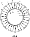
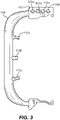
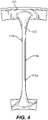
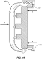
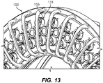
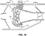
- FIG. 2-16 Other embodiments and/or aspects of this disclosure are shown in Figs. 2-16 .
- an internal fuel manifold 100 for a turbomachine (not shown) includes an outer ring 101.
- the outer ring 101 defines one or more fuel supply channels 103a, 103b, 103c, 103d configured to allow fuel flow around at least a portion of a circumference of the outer ring 101.
- the manifold 100 includes a plurality of branches 105 extending radially inward from the outer ring 101.
- the branches 105 include a high aspect ratio shape.
- the branches 105 can be thin (e.g., in the circumferential direction of outer ring 101) to reduce blockage of airflow therethrough.
- the plurality of branches 105 each include one or more branch fuel channels 107a, 107b, 107c in fluid communication with at least one of the one or more fuel supply channels 103, 103b, 103c, 103d.
- the manifold 100 includes an inner ring 109 (e.g., defined by a plurality of inner ring segments 111) extending from the plurality of branches 105.
- the inner ring 109 can be segmented to accommodate thermal expansion such that the inner ring 109 is comprised of detached segments 111 which can move relative to each other due to thermal movement. Any other configuration for the inner ring 109 is contemplated herein.
- the inner ring 109 and the outer ring 101 are configured to receive a fuel injector and combustor assembly 126 (e.g., as shown in Figs. 9-16 ) therebetween and to allow retaining of the fuel injector assembly and combustor assembly to the internal fuel manifold 100.
- the inner ring and/or the bottom portion 106 of one or more branches 105 can be solid to improve stiffness, for example.
- one or more of the branches 105 can include a pull handle shape as shown such that the branch 105 extends axially forward from the outer ring 101 and the inner ring 109.
- Each branch 105 can include the same shape, or any suitable branches 105 can have different shaped.
- One or more branches 105 can include an enlarging profile at the bases 105a, 105b thereof which can contributes to stiffness.
- the shape of the branches 105 can be optimized for weight and/or air blockage reduction and to have sufficient structural strength.
- the branches 105 can include any suitable shape.
- the manifold 100 includes one or more injector connectors 113a, 113b, 113c extending axially aft from each branch 105.
- Each injector connector is in fluid communication with a branch fuel channel 107a, 107b, 107c and is configured to connect to a fuel injector (e.g., as shown in Figs. 10-15 ).
- the one or more branch fuel channels 107a, 107b, 107c can include a plurality of branch fuel channels 107a, 107b, 107c as shown (e.g., all branches 105 can include the same number, type, and/or pattern or any other suitable number, type, or pattern).
- the at least one or more injector connectors 113a, 113b, 113c can include a plurality of injector connectors 113a, 113b, 113c, for example.
- each branch fuel channel 107a, 107b, 107c can be connected to a respective injector connector 113a, 113b, 113c, respectively, for example.
- the one or more fuel supply channels 103a, 103b, 103c, 103d can include a plurality of fuel supply channels 103a, 103b, 103c, 103d, e.g., as shown.
- the plurality of fuel supply channels 103a, 103b, 103c, 103d can include at least as many fuel supply channels 103a, 103b, 103c, 103d as there are branch fuel channels 107a, 107b, 107c in each branch 105 such that each injector connector 113a, 113b, 113c can be supplied with fuel independent of other injector connectors 113a, 113b, 113c on the same branch 105.
- each fuel injector connector 113a, 113b, 113c can be independently supplied with fuel allowing control over each fuel injector (e.g., as shown in Figs. 9-16 ) connected thereto which can allow for more efficient control and operation of the combustor.
- the plurality of injector connectors 113a, 113b, 113c can be disposed radially along the branch to form circumferential rows 115a, 115b, 115c with injector connectors 113a, 113b, 113c of other branches 105.
- each of the plurality of injector connectors 113a, 113b, 113c can extend from the branch 105 in a different direction.
- a fuel injector system 121 can include a fuel manifold 100 as disclosed herein, a combustor dome 123 mounted to the fuel manifold 100 with one or more retainer rings 119, and a plurality of fuel injectors 125a, 125b, 125c disposed in the combustor dome 123.
- Each fuel injector 125a, 125b, 125c can be connected to a fuel injector connector 113a, 113b, 113c of the fuel manifold 100 and be configured to mix air and fuel.
- the fuel injectors 125a, 125b, 125c can be arranged in circumferential rows in certain embodiments to align with a corresponding fuel injector connector 113a, 113b, 113c. As shown, e.g., in Fig. 11 and 15 , the fuel injectors 125a, 125b, 125c can be positioned such that minimal, if any, air blockage from the branches 105 is experienced. For example, the fuel injectors 125a, 125b, 125c may not pass under the branches 105.
- the combustor dome 123 can be made of a ceramic composite or any other suitable material, and other components can be made of any suitable material such as a suitable metal, ceramic, or composite, for example.
- the combustor dome 123 can be mounted to the fuel manifold 100 with one or more (e.g., two as shown) retaining rings 119 which press against the combustor dome 123 to provide positive force to engage each fuel injector 125a, 125b, 125c with each fuel injector connector 113a, 113b, 113c.
- the two retainer rings 119 can include combustor seals 127.
- the retainer rings 119 can be an elastic element configured to provide compressive force (e.g., a c-seal) shaped to operate as a bayonet fitting (e.g., by inserting and turning) to lock in place and provide compression.
- the system 121 can include a combustor liner 129a, 129b (e.g., comprised of an inner combustor cone 129a and an outer combustor cone 129b) disposed between the retainer rings 119 in contact with the combustor seals 127.
- the combustor line 129a, 129b can be a short, largely featureless device compared to traditional combustors because the dome 123 can admit all combustion air needed.
- the plurality of fuel injectors 125a, 125b, 125c can be disposed in the combustor dome 123 in a plurality of circumferential rows as shown to allow radial fuel staging.
- each fuel injector 125a, 125c in a radially outward row and radially inward row can be angled relative to an axial axis to effuse fuel and air into the combustor liner 129a, 129b parallel to or away from walls of the combustor liner to prevent impingement on the walls of the combustor liner 129a, 129b.
- each of the fuel injectors 125a, 125b, 125c can include one or more standoff features 131 configured to mate with one or more locator apertures 133 defined in the combustor dome 123 to orient each fuel injector 125a, 125b, 125c on the combustor dome 123 to such that each fuel injector 125a, 125b, 125c aligns with each fuel injector connector 113a, 113b, 113c.
- the plurality of fuel injectors includes 125a, 125b, 125c about 90 or more fuel injectors (e.g., about 180, about 250, or any large number of injection points).
- any suitable components can be manufacture in any suitable manner.
- one or more components e.g., the manifold 100
- Embodiments include three or more (e.g., four) separately controlled fuel channels to control flow volume to the nozzles.
- Individual channels can connect the main manifold to fuel injectors.
- each channel feeds different "radial row" (a row defined by a circumferential line).
- the fourth channel 101d can be reserved to have pilot flow channels connected, e.g., for minimum fuel to maintain light.
- the middle row can be connected to fourth channel 101d, or any other suitable pattern or arrangement (e.g., a single branch and/or any other suitable nozzle location). Any suitable configuration is contemplated herein.
- Reduction of air flow blockage can be accomplished by thin struts containing the fuel channels.
- the branches can be stiffened and strengthened by the out and inner ring elements which can act as clasps to attach the combustor segments.
- the combustor openings can be located relative to these rings rather than the out case.
- a cowling 141 e.g. a pressure recovery cowling
- a support structure 143 can provide heat shielding.
- the manifold 100 can attach to the cowling 141 and/or support structure 143 in any suitable manner.
- fuel inlets 145 can connect to external fuel lines in one or more locations around the circumference of the outer ring 101 of the manifold.
- Each inlet channel can be separately controlled to provide independent fuel flow in each channel.
- a multi-point injection arrangement offers outstanding combustion performance without premixing.
- Figs. 13 and 14 shows a high density of injectors, which on top of increased efficiency, also causes cooling of the combustor dome 123.
- the turbine will see much more uniform heat distribution by having more injection points than traditional systems, for example.
- Embodiments of a manifold locate individual injectors closely to combustor dome and allow reduction of fuel impingement on walls of the combustor.
- the branches 105 can also be shaped such that they remove swirl from compressor air due to their shape (e.g., like a flat stator) which can be beneficial for each nozzle to function.
- Embodiments offer fully assembled structure that is still but offers minimal blockage to air flow.
- Embodiments of the fuel injection system are integrated into combustor design.
- Embodiments include a combustor that is dramatically reduced in length (e.g., reduced by half or more). For example, large dome flow reduces combustor hot wall length and reduces composite cost and weight, eliminates combustor holes and complexity, and improves durability.
- Embodiments can operate at high temperatures with low emissions combustion which can suit advanced, high pressure engines, for example.
- Embodiments include an internal fuel manifold integrated with the combustor support, air cowls and combustor dome tiles, and large diameter nozzle air flow channels integrated into dome tiles to maximize the backside cooling by the combustion air prior to entering the combustor.
- Embodiments include increased injection sites which can permit very rapid mixing allowing for extremely short combustors.
- Embodiments allow holes in the high pressure casing to be minimized due to reduced engine weight.
- Embodiments allow radial fuel staging that can permit radial temperature profile control for the turbine.
- Embodiments allow extremely low temperature pattern factor that can be achieved for the turbine.
- Embodiments allow extremely low emissions to be achieved.
- Embodiments include very high durability, low cost mixers and better mechanical integration with the combustor.
Landscapes
- Engineering & Computer Science (AREA)
- Chemical & Material Sciences (AREA)
- Combustion & Propulsion (AREA)
- Mechanical Engineering (AREA)
- General Engineering & Computer Science (AREA)
Claims (15)
- Interner Brennstoffverteiler (100) für eine Turbomaschine, umfassend:einen Außenring (101), der einen oder mehrere Brennstoffversorgungskanäle (103a-103d ) definiert, die dazu konfiguriert sind, Brennstoffströmung, um mindestens einen Teil eines Umfangs des Außenrings (101) zu erlauben;eine Vielzahl von Verzweigungen (105), die sich von dem Außenring (101) radial nach innen erstreckt, wobei die Verzweigungen (105) eine Gestalt mit hohem Seitenverhältnis beinhalten, wobei die Vielzahl von Verzweigungen (105) einen oder mehrere Verzweigungsbrennstoffkanäle (107a-107c) in Fluidverbindung mit mindestens einem des einen oder der mehreren Brennstoffversorgungskanäle (103a-103d) beinhaltet;einen oder mehrere Injektorverbinder (113a-113c), die sich von jeder Verzweigung axial nach hinten erstrecken, wobei jeder Injektorverbinder mit einem Verzweigungsbrennstoffkanal in Fluidverbindung steht und dazu konfiguriert ist, mit einem Brennstoffinjektor verbunden zu werden; undeinen Innenring (109), der sich von der Vielzahl von Verzweigungen (105) erstreckt, wobei der Innenring (109) und der Außenring (101) dazu konfiguriert sind, dazwischen eine Brennstoffinjektor- und Brennkammeranordnung (126) aufzunehmen und ein Halten der Brennstoffinjektor- und Brennkammeranordnung (126) an dem internen Brennstoffverteiler (100) zu erlauben.
- Verteiler nach Anspruch 1, wobei ein oder mehrere Verzweigungsbrennstoffkanäle (107a-107c) eine Vielzahl von Verzweigungsbrennstoffkanälen beinhalten.
- Verteiler nach Anspruch 2, wobei der mindestens eine oder die mehreren Injektorverbinder (113a-113c) eine Vielzahl von Injektorverbindern beinhalten.
- Verteiler nach Anspruch 3, wobei jeder Verzweigungsbrennstoffkanal mit einem jeweiligen Injektorverbinder verbunden ist undwobei bevorzugt der eine oder die mehreren Brennstoffversorgungskanäle (103a-103d) eine Vielzahl von Brennstoffversorgungskanälen beinhalten, undwobei die Vielzahl von Brennstoffversorgungskanälen (103a-103d) mindestens so viele Brennstoffversorgungskanäle wie Verzweigungsbrennstoffkanäle (107a-107c) in jeder Verzweigung derart beinhaltet, dass jeder Injektorverbinder unabhängig von anderen Injektorverbindern auf derselben Verzweigung mit Brennstoff versorgt werden kann.
- Verteiler nach Anspruch 3, wobei die Vielzahl von Injektorverbindern (113a-113c) radial entlang der Verzweigung angeordnet ist, um umfängliche Reihen mit Injektorverbindern anderer Verzweigungen zu bilden.
- Verteiler nach Anspruch 3, wobei sich jeder der Vielzahl von Injektorverbindern (113a-113c) von der Verzweigung in einer unterschiedlichen Richtung erstreckt.
- Verteiler nach einem vorstehenden Anspruch, wobei der Innenring (109) segmentiert ist, um Wärmedehnung derart aufzunehmen, dass der Innenring (109) aus getrennten Segmenten, die sich relativ zueinander bewegen können, besteht.
- Verteiler nach einem vorstehenden Anspruch, wobei die Verzweigung eine Ziehgriffgestalt derart beinhaltet, dass sich die Verzweigung von dem Außenring (101) und dem Innenring (109) axial nach vorn erstreckt.
- Verteiler nach einem vorstehenden Anspruch, wobei der Außenring und der Innenring einen Bajonettflansch (117) zum Verbinden der Brennstoffinjektoranordnung unter Verwendung eines oder mehrerer Halteringe (119) definieren.
- Brennstoffinjektorsystem, umfassend:einen Brennstoffverteiler (100) nach Anspruch 1;eine Brennkammerkuppel (123), die mit einem oder mehreren Halteringen an dem Brennstoffverteiler montiert ist; undeine Vielzahl von Brennstoffinjektoren (125a-125c), die in der Brennkammerkuppel (123) angeordnet ist, wobei jeder Brennstoffinjektor mit einem Brennstoffinjektorverbinder des Brennstoffverteilers verbunden und dazu konfiguriert ist, Luft und Brennstoff zu mischen.
- System nach Anspruch 10, wobei die Brennkammerkuppel (123) an dem Brennstoffverteiler mit zwei Halteringen (119) montiert ist, die gegen die Brennkammerkuppel (123) drücken, um eine positive Kraft bereitzustellen, um jeden Brennstoffinjektor mit jedem Brennstoffinjektorverbinder in Eingriff zu bringen.
- System nach Anspruch 11, wobei die zwei Halteringe (119) Brennkammerdichtungen beinhalten und bevorzugt ferner einen Brennkammereinsatz (129a, 129b) umfassen, der zwischen den Halteringen (119) in Kontakt mit den Brennkammerdichtungen angeordnet ist, und bevorzugt
- System nach einem der Ansprüche 10-12, wobei die Vielzahl von Brennstoffinjektoren bevorzugt in einer Vielzahl umfänglicher Reihen angeordnet ist, um eine radiale Brennstoffstufung zu ermöglichen, undwobei bevorzugt jeder Brennstoffinjektor in einer radial äußeren Reihe und einer radial inneren Reihe relativ zu einer axialen Achse abgewinkelt ist, um Brennstoff und Luft parallel zu Wänden des Brennkammereinsatzes (129a, 129b) oder davon weg in den Brennkammereinsatz (129a, 129b) auszuströmen, um Auftreffen auf den Wänden des Brennkammereinsatzes (129a, 129b) zu verhindern, undwobei bevorzugter jeder der Brennstoffinjektoren ein oder mehrere Abstandsmerkmale (131) beinhaltet, die dazu konfiguriert sind, mit einer oder mehreren Positionierungs-öffnungen (133), die in der Brennkammerkuppel (123) definiert sind, zusammenzupassen, um jeden Brennstoffinjektor auf der Brennkammerkuppel (123) derart auszurichten, das sich jeder Brennstoffinjektor mit jedem Brennstoffinjektorverbinder ausrichtet.
- System nach einem der Ansprüche 10-13, wobei die Vielzahl von Brennstoffinjektoren etwa 90 oder mehr Brennstoffinjektoren beinhaltet.
- Verfahren zum Herstellen eines internen Brennstoffverteilers für eine Turbomaschine, umfassend:
additives Fertigen:eines Außenrings, der einen oder mehrere Brennstoffversorgungskanäle definiert, die dazu konfiguriert sind, eine Brennstoffströmung um mindestens einen Teil eines Umfangs des Außenrings zu erlauben;einer Vielzahl von Verzweigungen, die sich von dem Außenring radial nach innen erstreckt, wobei die Verzweigungen eine Gestalt mit hohem Seitenverhältnis beinhalten, wobei die Vielzahl von Verzweigungen einen oder mehrere Verzweigungsbrennstoffkanäle in Fluidverbindung mit mindestens einem des einen oder der mehreren Brennstoffversorgungskanäle beinhaltet;einen oder mehrere Brennstoffinjektorverbinder, die sich von jeder Verzweigung axial nach hinten erstrecken, wobei jeder Injektorverbinder mit einem Verzweigungsbrennstoffkanal in Fluidverbindung steht und dazu konfiguriert ist, mit einem Brennstoffinjektor verbunden zu werden; undeinen Innenring, der sich von der Vielzahl von Verzweigungen erstreckt, wobei der Innenring und der Außenring dazu konfiguriert sind, dazwischen eine Brennstoffinjektor- und Brennkammeranordnung aufzunehmen und ein Halten der Brennstoffinjektor- und Brennkammeranordnung an dem inneren Brennstoffverteiler zu erlauben.
Applications Claiming Priority (1)
| Application Number | Priority Date | Filing Date | Title |
|---|---|---|---|
| US15/949,776 US10605171B2 (en) | 2018-04-10 | 2018-04-10 | Fuel nozzle manifold systems for turbomachines |
Publications (2)
| Publication Number | Publication Date |
|---|---|
| EP3553293A1 EP3553293A1 (de) | 2019-10-16 |
| EP3553293B1 true EP3553293B1 (de) | 2022-11-23 |
Family
ID=66182350
Family Applications (1)
| Application Number | Title | Priority Date | Filing Date |
|---|---|---|---|
| EP19167652.7A Active EP3553293B1 (de) | 2018-04-10 | 2019-04-05 | Brennstoffverteilersystem für turbomaschinen |
Country Status (2)
| Country | Link |
|---|---|
| US (1) | US10605171B2 (de) |
| EP (1) | EP3553293B1 (de) |
Families Citing this family (8)
| Publication number | Priority date | Publication date | Assignee | Title |
|---|---|---|---|---|
| US11156162B2 (en) * | 2018-05-23 | 2021-10-26 | General Electric Company | Fluid manifold damper for gas turbine engine |
| US11187155B2 (en) * | 2019-07-22 | 2021-11-30 | Delavan Inc. | Sectional fuel manifolds |
| US11248528B2 (en) * | 2019-10-18 | 2022-02-15 | Delavan Inc. | Internal fuel manifolds |
| US20230235702A1 (en) * | 2022-01-21 | 2023-07-27 | Delavan Inc. | Connecting fuel injectors and nozzles to manifolds |
| US12241419B2 (en) * | 2022-08-25 | 2025-03-04 | Collins Engine Nozzles, Inc. | Fuel injectors assemblies with tangential flow component |
| US12117174B2 (en) | 2023-02-14 | 2024-10-15 | Collins Engine Nozzles, Inc. | Combustor section support structures |
| GB202306498D0 (en) | 2023-05-03 | 2023-06-14 | Rolls Royce Plc | Gas turbine engine |
| US12613035B1 (en) * | 2024-09-16 | 2026-04-28 | General Electric Company | Combustion section for a turbine engine |
Family Cites Families (23)
| Publication number | Priority date | Publication date | Assignee | Title |
|---|---|---|---|---|
| GB840529A (en) | 1957-06-20 | 1960-07-06 | Rolls Royce | Improvements in or relating to combustion equipment of gas turbine engines |
| US2970438A (en) | 1958-03-04 | 1961-02-07 | Curtiss Wright Corp | Circular fuel spray bars |
| US4028888A (en) * | 1974-05-03 | 1977-06-14 | Norwalk-Turbo Inc. | Fuel distribution manifold to an annular combustion chamber |
| GB2036296B (en) * | 1978-11-20 | 1982-12-01 | Rolls Royce | Gas turbine |
| US4402184A (en) * | 1980-12-08 | 1983-09-06 | International Harvester Company | Gas turbine engines |
| US5036657A (en) * | 1987-06-25 | 1991-08-06 | General Electric Company | Dual manifold fuel system |
| US4903478A (en) * | 1987-06-25 | 1990-02-27 | General Electric Company | Dual manifold fuel system |
| US5168698A (en) * | 1991-04-22 | 1992-12-08 | General Electric Company | Fuel manifold system for gas turbine engines |
| US5289685A (en) * | 1992-11-16 | 1994-03-01 | General Electric Company | Fuel supply system for a gas turbine engine |
| US7703286B2 (en) * | 2006-09-22 | 2010-04-27 | Pratt & Whitney Canada Corp. | Internal fuel manifold and fuel fairing interface |
| US7320212B2 (en) * | 2004-01-27 | 2008-01-22 | Pratt & Whitney Canada Corp. | Side-fed shielded internal fuel manifold inlet tube |
| WO2013188723A1 (en) * | 2012-06-15 | 2013-12-19 | General Electric Company | Fluid conduit |
| US9810186B2 (en) * | 2013-01-02 | 2017-11-07 | Parker-Hannifin Corporation | Direct injection multipoint nozzle |
| WO2015060956A2 (en) * | 2013-10-04 | 2015-04-30 | United Technologies Corporation | Automatic control of turbine blade temperature during gas turbine engine operation |
| US10400674B2 (en) * | 2014-05-09 | 2019-09-03 | United Technologies Corporation | Cooled fuel injector system for a gas turbine engine and method for operating the same |
| US10578021B2 (en) | 2015-06-26 | 2020-03-03 | Delavan Inc | Combustion systems |
| US10087845B2 (en) | 2015-11-30 | 2018-10-02 | General Electric Company | Pressure damping device for fuel manifold |
| US10465909B2 (en) * | 2016-11-04 | 2019-11-05 | General Electric Company | Mini mixing fuel nozzle assembly with mixing sleeve |
| US10731859B2 (en) * | 2017-07-21 | 2020-08-04 | Delavan Inc. | Fuel nozzles |
| US20190234311A1 (en) * | 2018-01-29 | 2019-08-01 | Pratt & Whitney Canada Corp. | Thermal insulation for fluid carrying components |
| US11131458B2 (en) * | 2018-04-10 | 2021-09-28 | Delavan Inc. | Fuel injectors for turbomachines |
| US10788214B2 (en) * | 2018-04-10 | 2020-09-29 | Delavan Inc. | Fuel injectors for turbomachines having inner air swirling |
| US11143406B2 (en) * | 2018-04-10 | 2021-10-12 | Delavan Inc. | Fuel injectors having air sealing structures |
-
2018
- 2018-04-10 US US15/949,776 patent/US10605171B2/en active Active
-
2019
- 2019-04-05 EP EP19167652.7A patent/EP3553293B1/de active Active
Also Published As
| Publication number | Publication date |
|---|---|
| EP3553293A1 (de) | 2019-10-16 |
| US20190309686A1 (en) | 2019-10-10 |
| US10605171B2 (en) | 2020-03-31 |
Similar Documents
| Publication | Publication Date | Title |
|---|---|---|
| EP3553383B1 (de) | Kraftstoffinjektoren für turbomaschinen | |
| EP3553293A1 (de) | Brennstoffverteilersystem für turbomaschinen | |
| US11906167B2 (en) | Fuel injectors for multipoint arrays | |
| EP3495737B1 (de) | Verbrennungssysteme | |
| EP3431878B1 (de) | Kraftstoffdüsen | |
| EP3109548B1 (de) | Verbrennungssysteme mit im brennkammerdom integriertem brennstoffverteiler | |
| US7082770B2 (en) | Flow sleeve for a low NOx combustor | |
| EP1400754B1 (de) | Vormischender Pilotbrenner für eine Gasturbine | |
| EP0907053B1 (de) | Flanschvorrichtung für eine Trennungskrone zwischen konzentrischen Brennerringen einer Mehrstufenbrennkammer | |
| US11674687B2 (en) | Fuel manifolds | |
| EP3598003B1 (de) | Mehrpunkteinspritzungssystem | |
| US11585275B2 (en) | Internal manifold for multipoint injection | |
| US11187155B2 (en) | Sectional fuel manifolds |
Legal Events
| Date | Code | Title | Description |
|---|---|---|---|
| PUAI | Public reference made under article 153(3) epc to a published international application that has entered the european phase |
Free format text: ORIGINAL CODE: 0009012 |
|
| STAA | Information on the status of an ep patent application or granted ep patent |
Free format text: STATUS: THE APPLICATION HAS BEEN PUBLISHED |
|
| AK | Designated contracting states |
Kind code of ref document: A1 Designated state(s): AL AT BE BG CH CY CZ DE DK EE ES FI FR GB GR HR HU IE IS IT LI LT LU LV MC MK MT NL NO PL PT RO RS SE SI SK SM TR |
|
| AX | Request for extension of the european patent |
Extension state: BA ME |
|
| STAA | Information on the status of an ep patent application or granted ep patent |
Free format text: STATUS: REQUEST FOR EXAMINATION WAS MADE |
|
| 17P | Request for examination filed |
Effective date: 20191217 |
|
| RBV | Designated contracting states (corrected) |
Designated state(s): AL AT BE BG CH CY CZ DE DK EE ES FI FR GB GR HR HU IE IS IT LI LT LU LV MC MK MT NL NO PL PT RO RS SE SI SK SM TR |
|
| RAP3 | Party data changed (applicant data changed or rights of an application transferred) |
Owner name: COLLINS ENGINE NOZZLES, INC. |
|
| GRAP | Despatch of communication of intention to grant a patent |
Free format text: ORIGINAL CODE: EPIDOSNIGR1 |
|
| STAA | Information on the status of an ep patent application or granted ep patent |
Free format text: STATUS: GRANT OF PATENT IS INTENDED |
|
| INTG | Intention to grant announced |
Effective date: 20220621 |
|
| GRAS | Grant fee paid |
Free format text: ORIGINAL CODE: EPIDOSNIGR3 |
|
| GRAA | (expected) grant |
Free format text: ORIGINAL CODE: 0009210 |
|
| STAA | Information on the status of an ep patent application or granted ep patent |
Free format text: STATUS: THE PATENT HAS BEEN GRANTED |
|
| AK | Designated contracting states |
Kind code of ref document: B1 Designated state(s): AL AT BE BG CH CY CZ DE DK EE ES FI FR GB GR HR HU IE IS IT LI LT LU LV MC MK MT NL NO PL PT RO RS SE SI SK SM TR |
|
| REG | Reference to a national code |
Ref country code: GB Ref legal event code: FG4D |
|
| REG | Reference to a national code |
Ref country code: CH Ref legal event code: EP |
|
| REG | Reference to a national code |
Ref country code: DE Ref legal event code: R096 Ref document number: 602019022129 Country of ref document: DE |
|
| REG | Reference to a national code |
Ref country code: AT Ref legal event code: REF Ref document number: 1533268 Country of ref document: AT Kind code of ref document: T Effective date: 20221215 |
|
| REG | Reference to a national code |
Ref country code: IE Ref legal event code: FG4D |
|
| REG | Reference to a national code |
Ref country code: LT Ref legal event code: MG9D |
|
| REG | Reference to a national code |
Ref country code: NL Ref legal event code: MP Effective date: 20221123 |
|
| REG | Reference to a national code |
Ref country code: AT Ref legal event code: MK05 Ref document number: 1533268 Country of ref document: AT Kind code of ref document: T Effective date: 20221123 |
|
| PG25 | Lapsed in a contracting state [announced via postgrant information from national office to epo] |
Ref country code: SE Free format text: LAPSE BECAUSE OF FAILURE TO SUBMIT A TRANSLATION OF THE DESCRIPTION OR TO PAY THE FEE WITHIN THE PRESCRIBED TIME-LIMIT Effective date: 20221123 Ref country code: PT Free format text: LAPSE BECAUSE OF FAILURE TO SUBMIT A TRANSLATION OF THE DESCRIPTION OR TO PAY THE FEE WITHIN THE PRESCRIBED TIME-LIMIT Effective date: 20230323 Ref country code: NO Free format text: LAPSE BECAUSE OF FAILURE TO SUBMIT A TRANSLATION OF THE DESCRIPTION OR TO PAY THE FEE WITHIN THE PRESCRIBED TIME-LIMIT Effective date: 20230223 Ref country code: LT Free format text: LAPSE BECAUSE OF FAILURE TO SUBMIT A TRANSLATION OF THE DESCRIPTION OR TO PAY THE FEE WITHIN THE PRESCRIBED TIME-LIMIT Effective date: 20221123 Ref country code: FI Free format text: LAPSE BECAUSE OF FAILURE TO SUBMIT A TRANSLATION OF THE DESCRIPTION OR TO PAY THE FEE WITHIN THE PRESCRIBED TIME-LIMIT Effective date: 20221123 Ref country code: ES Free format text: LAPSE BECAUSE OF FAILURE TO SUBMIT A TRANSLATION OF THE DESCRIPTION OR TO PAY THE FEE WITHIN THE PRESCRIBED TIME-LIMIT Effective date: 20221123 Ref country code: AT Free format text: LAPSE BECAUSE OF FAILURE TO SUBMIT A TRANSLATION OF THE DESCRIPTION OR TO PAY THE FEE WITHIN THE PRESCRIBED TIME-LIMIT Effective date: 20221123 |
|
| PG25 | Lapsed in a contracting state [announced via postgrant information from national office to epo] |
Ref country code: RS Free format text: LAPSE BECAUSE OF FAILURE TO SUBMIT A TRANSLATION OF THE DESCRIPTION OR TO PAY THE FEE WITHIN THE PRESCRIBED TIME-LIMIT Effective date: 20221123 Ref country code: PL Free format text: LAPSE BECAUSE OF FAILURE TO SUBMIT A TRANSLATION OF THE DESCRIPTION OR TO PAY THE FEE WITHIN THE PRESCRIBED TIME-LIMIT Effective date: 20221123 Ref country code: LV Free format text: LAPSE BECAUSE OF FAILURE TO SUBMIT A TRANSLATION OF THE DESCRIPTION OR TO PAY THE FEE WITHIN THE PRESCRIBED TIME-LIMIT Effective date: 20221123 Ref country code: IS Free format text: LAPSE BECAUSE OF FAILURE TO SUBMIT A TRANSLATION OF THE DESCRIPTION OR TO PAY THE FEE WITHIN THE PRESCRIBED TIME-LIMIT Effective date: 20230323 Ref country code: HR Free format text: LAPSE BECAUSE OF FAILURE TO SUBMIT A TRANSLATION OF THE DESCRIPTION OR TO PAY THE FEE WITHIN THE PRESCRIBED TIME-LIMIT Effective date: 20221123 Ref country code: GR Free format text: LAPSE BECAUSE OF FAILURE TO SUBMIT A TRANSLATION OF THE DESCRIPTION OR TO PAY THE FEE WITHIN THE PRESCRIBED TIME-LIMIT Effective date: 20230224 |
|
| PG25 | Lapsed in a contracting state [announced via postgrant information from national office to epo] |
Ref country code: NL Free format text: LAPSE BECAUSE OF FAILURE TO SUBMIT A TRANSLATION OF THE DESCRIPTION OR TO PAY THE FEE WITHIN THE PRESCRIBED TIME-LIMIT Effective date: 20221123 |
|
| P01 | Opt-out of the competence of the unified patent court (upc) registered |
Effective date: 20230530 |
|
| PG25 | Lapsed in a contracting state [announced via postgrant information from national office to epo] |
Ref country code: SM Free format text: LAPSE BECAUSE OF FAILURE TO SUBMIT A TRANSLATION OF THE DESCRIPTION OR TO PAY THE FEE WITHIN THE PRESCRIBED TIME-LIMIT Effective date: 20221123 Ref country code: RO Free format text: LAPSE BECAUSE OF FAILURE TO SUBMIT A TRANSLATION OF THE DESCRIPTION OR TO PAY THE FEE WITHIN THE PRESCRIBED TIME-LIMIT Effective date: 20221123 Ref country code: EE Free format text: LAPSE BECAUSE OF FAILURE TO SUBMIT A TRANSLATION OF THE DESCRIPTION OR TO PAY THE FEE WITHIN THE PRESCRIBED TIME-LIMIT Effective date: 20221123 Ref country code: DK Free format text: LAPSE BECAUSE OF FAILURE TO SUBMIT A TRANSLATION OF THE DESCRIPTION OR TO PAY THE FEE WITHIN THE PRESCRIBED TIME-LIMIT Effective date: 20221123 Ref country code: CZ Free format text: LAPSE BECAUSE OF FAILURE TO SUBMIT A TRANSLATION OF THE DESCRIPTION OR TO PAY THE FEE WITHIN THE PRESCRIBED TIME-LIMIT Effective date: 20221123 |
|
| REG | Reference to a national code |
Ref country code: DE Ref legal event code: R097 Ref document number: 602019022129 Country of ref document: DE |
|
| PG25 | Lapsed in a contracting state [announced via postgrant information from national office to epo] |
Ref country code: SK Free format text: LAPSE BECAUSE OF FAILURE TO SUBMIT A TRANSLATION OF THE DESCRIPTION OR TO PAY THE FEE WITHIN THE PRESCRIBED TIME-LIMIT Effective date: 20221123 Ref country code: AL Free format text: LAPSE BECAUSE OF FAILURE TO SUBMIT A TRANSLATION OF THE DESCRIPTION OR TO PAY THE FEE WITHIN THE PRESCRIBED TIME-LIMIT Effective date: 20221123 |
|
| PLBE | No opposition filed within time limit |
Free format text: ORIGINAL CODE: 0009261 |
|
| STAA | Information on the status of an ep patent application or granted ep patent |
Free format text: STATUS: NO OPPOSITION FILED WITHIN TIME LIMIT |
|
| 26N | No opposition filed |
Effective date: 20230824 |
|
| PG25 | Lapsed in a contracting state [announced via postgrant information from national office to epo] |
Ref country code: SI Free format text: LAPSE BECAUSE OF FAILURE TO SUBMIT A TRANSLATION OF THE DESCRIPTION OR TO PAY THE FEE WITHIN THE PRESCRIBED TIME-LIMIT Effective date: 20221123 |
|
| REG | Reference to a national code |
Ref country code: CH Ref legal event code: PL |
|
| PG25 | Lapsed in a contracting state [announced via postgrant information from national office to epo] |
Ref country code: LU Free format text: LAPSE BECAUSE OF NON-PAYMENT OF DUE FEES Effective date: 20230405 |
|
| REG | Reference to a national code |
Ref country code: BE Ref legal event code: MM Effective date: 20230430 |
|
| PG25 | Lapsed in a contracting state [announced via postgrant information from national office to epo] |
Ref country code: MC Free format text: LAPSE BECAUSE OF FAILURE TO SUBMIT A TRANSLATION OF THE DESCRIPTION OR TO PAY THE FEE WITHIN THE PRESCRIBED TIME-LIMIT Effective date: 20221123 |
|
| PG25 | Lapsed in a contracting state [announced via postgrant information from national office to epo] |
Ref country code: MC Free format text: LAPSE BECAUSE OF FAILURE TO SUBMIT A TRANSLATION OF THE DESCRIPTION OR TO PAY THE FEE WITHIN THE PRESCRIBED TIME-LIMIT Effective date: 20221123 Ref country code: LI Free format text: LAPSE BECAUSE OF NON-PAYMENT OF DUE FEES Effective date: 20230430 Ref country code: CH Free format text: LAPSE BECAUSE OF NON-PAYMENT OF DUE FEES Effective date: 20230430 |
|
| REG | Reference to a national code |
Ref country code: IE Ref legal event code: MM4A |
|
| PG25 | Lapsed in a contracting state [announced via postgrant information from national office to epo] |
Ref country code: BE Free format text: LAPSE BECAUSE OF NON-PAYMENT OF DUE FEES Effective date: 20230430 |
|
| PG25 | Lapsed in a contracting state [announced via postgrant information from national office to epo] |
Ref country code: IE Free format text: LAPSE BECAUSE OF NON-PAYMENT OF DUE FEES Effective date: 20230405 |
|
| PG25 | Lapsed in a contracting state [announced via postgrant information from national office to epo] |
Ref country code: IE Free format text: LAPSE BECAUSE OF NON-PAYMENT OF DUE FEES Effective date: 20230405 |
|
| PG25 | Lapsed in a contracting state [announced via postgrant information from national office to epo] |
Ref country code: IT Free format text: LAPSE BECAUSE OF FAILURE TO SUBMIT A TRANSLATION OF THE DESCRIPTION OR TO PAY THE FEE WITHIN THE PRESCRIBED TIME-LIMIT Effective date: 20221123 |
|
| PG25 | Lapsed in a contracting state [announced via postgrant information from national office to epo] |
Ref country code: BG Free format text: LAPSE BECAUSE OF FAILURE TO SUBMIT A TRANSLATION OF THE DESCRIPTION OR TO PAY THE FEE WITHIN THE PRESCRIBED TIME-LIMIT Effective date: 20221123 |
|
| PG25 | Lapsed in a contracting state [announced via postgrant information from national office to epo] |
Ref country code: BG Free format text: LAPSE BECAUSE OF FAILURE TO SUBMIT A TRANSLATION OF THE DESCRIPTION OR TO PAY THE FEE WITHIN THE PRESCRIBED TIME-LIMIT Effective date: 20221123 |
|
| PGFP | Annual fee paid to national office [announced via postgrant information from national office to epo] |
Ref country code: DE Payment date: 20250319 Year of fee payment: 7 |
|
| PG25 | Lapsed in a contracting state [announced via postgrant information from national office to epo] |
Ref country code: CY Free format text: LAPSE BECAUSE OF FAILURE TO SUBMIT A TRANSLATION OF THE DESCRIPTION OR TO PAY THE FEE WITHIN THE PRESCRIBED TIME-LIMIT; INVALID AB INITIO Effective date: 20190405 |
|
| PG25 | Lapsed in a contracting state [announced via postgrant information from national office to epo] |
Ref country code: HU Free format text: LAPSE BECAUSE OF FAILURE TO SUBMIT A TRANSLATION OF THE DESCRIPTION OR TO PAY THE FEE WITHIN THE PRESCRIBED TIME-LIMIT; INVALID AB INITIO Effective date: 20190405 |
|
| PG25 | Lapsed in a contracting state [announced via postgrant information from national office to epo] |
Ref country code: TR Free format text: LAPSE BECAUSE OF FAILURE TO SUBMIT A TRANSLATION OF THE DESCRIPTION OR TO PAY THE FEE WITHIN THE PRESCRIBED TIME-LIMIT Effective date: 20221123 |
|
| PGFP | Annual fee paid to national office [announced via postgrant information from national office to epo] |
Ref country code: GB Payment date: 20260319 Year of fee payment: 8 |
|
| PGFP | Annual fee paid to national office [announced via postgrant information from national office to epo] |
Ref country code: FR Payment date: 20260319 Year of fee payment: 8 |