EP3553015B1 - Crane and method for operating a crane - Google Patents
Crane and method for operating a crane Download PDFInfo
- Publication number
- EP3553015B1 EP3553015B1 EP19163621.6A EP19163621A EP3553015B1 EP 3553015 B1 EP3553015 B1 EP 3553015B1 EP 19163621 A EP19163621 A EP 19163621A EP 3553015 B1 EP3553015 B1 EP 3553015B1
- Authority
- EP
- European Patent Office
- Prior art keywords
- configuration
- crane
- lifting system
- control unit
- structures
- Prior art date
- Legal status (The legal status is an assumption and is not a legal conclusion. Google has not performed a legal analysis and makes no representation as to the accuracy of the status listed.)
- Active
Links
Images


Classifications
-
- B—PERFORMING OPERATIONS; TRANSPORTING
- B66—HOISTING; LIFTING; HAULING
- B66C—CRANES; LOAD-ENGAGING ELEMENTS OR DEVICES FOR CRANES, CAPSTANS, WINCHES, OR TACKLES
- B66C13/00—Other constructional features or details
- B66C13/18—Control systems or devices
- B66C13/48—Automatic control of crane drives for producing a single or repeated working cycle; Program control
-
- B—PERFORMING OPERATIONS; TRANSPORTING
- B66—HOISTING; LIFTING; HAULING
- B66C—CRANES; LOAD-ENGAGING ELEMENTS OR DEVICES FOR CRANES, CAPSTANS, WINCHES, OR TACKLES
- B66C13/00—Other constructional features or details
- B66C13/18—Control systems or devices
- B66C13/46—Position indicators for suspended loads or for crane elements
-
- B—PERFORMING OPERATIONS; TRANSPORTING
- B66—HOISTING; LIFTING; HAULING
- B66C—CRANES; LOAD-ENGAGING ELEMENTS OR DEVICES FOR CRANES, CAPSTANS, WINCHES, OR TACKLES
- B66C15/00—Safety gear
- B66C15/04—Safety gear for preventing collisions, e.g. between cranes or trolleys operating on the same track
- B66C15/045—Safety gear for preventing collisions, e.g. between cranes or trolleys operating on the same track electrical
-
- B—PERFORMING OPERATIONS; TRANSPORTING
- B66—HOISTING; LIFTING; HAULING
- B66C—CRANES; LOAD-ENGAGING ELEMENTS OR DEVICES FOR CRANES, CAPSTANS, WINCHES, OR TACKLES
- B66C15/00—Safety gear
- B66C15/06—Arrangements or use of warning devices
- B66C15/065—Arrangements or use of warning devices electrical
-
- B—PERFORMING OPERATIONS; TRANSPORTING
- B66—HOISTING; LIFTING; HAULING
- B66C—CRANES; LOAD-ENGAGING ELEMENTS OR DEVICES FOR CRANES, CAPSTANS, WINCHES, OR TACKLES
- B66C23/00—Cranes comprising essentially a beam, boom, or triangular structure acting as a cantilever and mounted for translatory of swinging movements in vertical or horizontal planes or a combination of such movements, e.g. jib-cranes, derricks, tower cranes
- B66C23/18—Cranes comprising essentially a beam, boom, or triangular structure acting as a cantilever and mounted for translatory of swinging movements in vertical or horizontal planes or a combination of such movements, e.g. jib-cranes, derricks, tower cranes specially adapted for use in particular purposes
- B66C23/36—Cranes comprising essentially a beam, boom, or triangular structure acting as a cantilever and mounted for translatory of swinging movements in vertical or horizontal planes or a combination of such movements, e.g. jib-cranes, derricks, tower cranes specially adapted for use in particular purposes mounted on road or rail vehicles; Manually-movable jib-cranes for use in workshops; Floating cranes
- B66C23/42—Cranes comprising essentially a beam, boom, or triangular structure acting as a cantilever and mounted for translatory of swinging movements in vertical or horizontal planes or a combination of such movements, e.g. jib-cranes, derricks, tower cranes specially adapted for use in particular purposes mounted on road or rail vehicles; Manually-movable jib-cranes for use in workshops; Floating cranes with jibs of adjustable configuration, e.g. foldable
-
- B—PERFORMING OPERATIONS; TRANSPORTING
- B66—HOISTING; LIFTING; HAULING
- B66C—CRANES; LOAD-ENGAGING ELEMENTS OR DEVICES FOR CRANES, CAPSTANS, WINCHES, OR TACKLES
- B66C23/00—Cranes comprising essentially a beam, boom, or triangular structure acting as a cantilever and mounted for translatory of swinging movements in vertical or horizontal planes or a combination of such movements, e.g. jib-cranes, derricks, tower cranes
- B66C23/18—Cranes comprising essentially a beam, boom, or triangular structure acting as a cantilever and mounted for translatory of swinging movements in vertical or horizontal planes or a combination of such movements, e.g. jib-cranes, derricks, tower cranes specially adapted for use in particular purposes
- B66C23/36—Cranes comprising essentially a beam, boom, or triangular structure acting as a cantilever and mounted for translatory of swinging movements in vertical or horizontal planes or a combination of such movements, e.g. jib-cranes, derricks, tower cranes specially adapted for use in particular purposes mounted on road or rail vehicles; Manually-movable jib-cranes for use in workshops; Floating cranes
- B66C23/44—Jib-cranes adapted for attachment to standard vehicles, e.g. agricultural tractors
-
- B—PERFORMING OPERATIONS; TRANSPORTING
- B66—HOISTING; LIFTING; HAULING
- B66C—CRANES; LOAD-ENGAGING ELEMENTS OR DEVICES FOR CRANES, CAPSTANS, WINCHES, OR TACKLES
- B66C23/00—Cranes comprising essentially a beam, boom, or triangular structure acting as a cantilever and mounted for translatory of swinging movements in vertical or horizontal planes or a combination of such movements, e.g. jib-cranes, derricks, tower cranes
- B66C23/58—Cranes comprising essentially a beam, boom, or triangular structure acting as a cantilever and mounted for translatory of swinging movements in vertical or horizontal planes or a combination of such movements, e.g. jib-cranes, derricks, tower cranes arranged to carry out a desired sequence of operations automatically, e.g. hoisting followed by luffing and slewing
- B66C23/585—Cranes comprising essentially a beam, boom, or triangular structure acting as a cantilever and mounted for translatory of swinging movements in vertical or horizontal planes or a combination of such movements, e.g. jib-cranes, derricks, tower cranes arranged to carry out a desired sequence of operations automatically, e.g. hoisting followed by luffing and slewing electrical
-
- B—PERFORMING OPERATIONS; TRANSPORTING
- B66—HOISTING; LIFTING; HAULING
- B66C—CRANES; LOAD-ENGAGING ELEMENTS OR DEVICES FOR CRANES, CAPSTANS, WINCHES, OR TACKLES
- B66C23/00—Cranes comprising essentially a beam, boom, or triangular structure acting as a cantilever and mounted for translatory of swinging movements in vertical or horizontal planes or a combination of such movements, e.g. jib-cranes, derricks, tower cranes
- B66C23/62—Constructional features or details
- B66C23/64—Jibs
- B66C23/70—Jibs constructed of sections adapted to be assembled to form jibs or various lengths
- B66C23/701—Jibs constructed of sections adapted to be assembled to form jibs or various lengths telescopic
- B66C23/705—Jibs constructed of sections adapted to be assembled to form jibs or various lengths telescopic telescoped by hydraulic jacks
-
- B—PERFORMING OPERATIONS; TRANSPORTING
- B66—HOISTING; LIFTING; HAULING
- B66C—CRANES; LOAD-ENGAGING ELEMENTS OR DEVICES FOR CRANES, CAPSTANS, WINCHES, OR TACKLES
- B66C23/00—Cranes comprising essentially a beam, boom, or triangular structure acting as a cantilever and mounted for translatory of swinging movements in vertical or horizontal planes or a combination of such movements, e.g. jib-cranes, derricks, tower cranes
- B66C23/88—Safety gear
Definitions
- the present invention relates to a crane and a method for operating a crane. More particularly, the invention relates to a method for operating a crane to perform a task automatically without manual assistance.
- WO2015001401A1 discloses a crane and a method of controlling a crane that comprises a lift system configured to be arranged in a plurality of configurations.
- the lifting system comprises a plurality of structures that are movably arranged relative to each other and actuator adapted to move the structures relative to each other.
- WO2015113084A1 discloses a method for controlling a lorry crane according to the preamble of claim 1.
- the crane controller is configured to be operated in a first operating mode in which the crane can be freely operated by a user using control commands and in a second operating mode that can be activated by the user, in which the crane geometry is performed in a predetermined sequence of movements by the crane control is changeable.
- This solution only provides a single fixed path determined at a single fixed initial position.
- CN201358142Y discloses an automatic control system for a telescopic boom. This solution, however, only provides a fixed path determined on the basis of manually selected starting position and a manually selected ending position.
- the object of the present invention can be achieved by a method as defined in claim 1 and by a crane having the features as defined in claim 9.
- the method according to the invention is a method for controlling a lorry crane, having a lifting system configured to be arranged in a plurality of configurations, wherein the lifting system comprises a plurality of structures moveably arranged relative to each other and one or more actuators arranged to move the structures relative to each other, wherein the method comprises the following steps:
- the method is capable of continuously determining the most optimum path and automatically operate the crane accordingly. Moreover, the method makes it possible to operate a crane in a safer manner.
- the lifting system comprises a plurality of structures moveably arranged relative to each other. These structures may be a crane base, a column being rotatably attached to the crane base, a jib comprising a number of booms.
- the structures may comprise a plurality of booms displaceable arranged with respect to each other.
- the plurality of booms may preferably be arranged in a telescopical manner with respect to each other.
- the lifting system comprises one or more actuators arranged to move the structures relative to each other.
- the actuators may be of any suitable size and type.
- the actuators are formed as hydraulic cylinders.
- the method comprises the step of selecting a first configuration by means of a control system comprising an operable control unit.
- the method comprises the step of selecting a second configuration by means of the control unit.
- the first configuration and/or the second configuration may e.g. be selected from a predefined list or may be selected by any indication means e.g. by pointing out a position on a map on a user interface (e.g. a display).
- the first and/or second configurations may be positions (e.g. lifting positions of a load), it may alternatively be a configuration of a boom/crane arm such as an un-folded configuration of the boom/crane arm or a folded configuration of the boom/crane arm.
- the method comprises the step of activating the control unit to automatically bringing the lifting system from the first configuration into the second configuration by using one or more actuators.
- first configuration and/or the second configuration is a position of a load being carried by the crane or a position of a structure of the lifting system. This means that the first configuration and/or the second configuration can be defined by the position, at which a load carried by the crane or to be carried by the crane is located.
- first configuration and/or the second configuration are selected from a list being visibly available on a user interface.
- the list may include numbers and/or other text or symbols.
- one configuration may be the lifting system in a folded configuration, in which the lifting system takes up less space than during lifting tasks.
- one configuration may be the lifting system in an un-folded configuration, in which the lifting system is ready to lift a load (e.g. from a first position to another position).
- the method comprises the step of selecting the first configuration and/or the second configuration by indicating a position in a map displayed on a user interface or by using an external transmitter unit.
- the selecting process is eased in a user-friendly manner. Furthermore, in some applications it allows the operator to get an overview over the surrounding.
- the method comprises the step of keeping the structures in positions, in which the distance between the structures and one or more zones and/or positions is larger than a predefined length.
- the invention ensures that fragile objects are protected from impacts and contact with the lifting system. This is of major importance if a lorry crane carries fragile cargo that is not resistant to collision with the lifting system of the crane.
- the method is furthermore capable of protecting moving objects.
- the position of moving objects e.g. a human, an animal or a vehicle
- the method comprises the step of automatically stopping the actuators when the distance between the structures and the one or more zones and/or positions is equal to or smaller than the predefined length.
- the actuators it is possible to control the crane in a safe manner, in which collision with objects can be prevented.
- predefine the cab of a lorry to be a "safe zone", wherein the lifting system is required to be provided within a predefined minimum distance to the safe zone.
- the method comprises the step of automatically reducing the rotational and/or linear speed of one or more of the structures of the lifting system when the distance between the structures and the one or more zones and/or positions is equal to or smaller than the predefined length. Reducing the speed may be accomplished by controlling one or more of the actuators.
- the actuators it is possible to control the crane in an even more safe manner, because the speed of structures of the lifting system can be reduced when the structures approach predefined positions or zones.
- the method comprises the step of detecting one or more zones and/or positions by using one or more sensors.
- zones and/or positions are predefined or are set by default or set by the user/operator of the crane.
- the one or the one or more sensors is a camera, an ultrasonic sensor, a proximity sensor or an optic distance sensor.
- the method comprises the step of carrying out calculations in order to recognise one or more detected objects in order to make decisions according to a predefined scheme.
- a proximity sensor By using a proximity sensor, it is possible to detect if an object is within a predefined range from a predefined area (e.g. a structure of the lifting system).
- an optic distance sensor By using an optic distance sensor, it is possible to detect one or more distances optically.
- control unit comprises an object recognition unit configured to recognise one or more objects of predefined size and/or geometry and/or speed based on data provided by means of a camera.
- object recognition unit configured to recognise one or more objects and take this into account e.g. in order to stop the movement of the lifting system or to move the lifting system away from the object in order to avoid collision.
- the objects may be moving objects such as a human or an animal.
- the objects may also be a vehicle such as a car, a bicycle or a motorcycle.
- the method comprises the step of detecting the length of a structure of the lifting system and/or an angular position of a structure of the lifting system, wherein the control unit applies the length of a structure and/or the angular position of a structure to calculate a path, through which path the control unit brings the lifting system from the first configuration into the second configuration by using one or more actuators. Due to the constrains in the lifting system, detection of the length and angles of the structures of the lifting system will provide information sufficient to calculate one or more possible paths through which the lifting system can be brought from the first configuration into the second configuration by using one or more actuators.
- angular position may include an angle between adjacent structures or an angle of a structure relative to a predefined orientation (e.g. vertical or horizontal).
- the method comprises the step of regulating the speed (translation and rotation) of the structures in dependency of the distance between the structures and the one or more zones and/or positions.
- the crane according to the invention is a lorry crane that comprises a lifting system configured to be arranged in a plurality of configurations, wherein the lifting system comprises:
- the crane is capable of continuously determining the most optimum path and automatically operate the crane accordingly.
- the lifting system comprises a plurality of structures moveably arranged relative to each other. These structures may be a crane base, a column being rotatably attached to the crane base, a jib comprising a number of booms.
- the structures may comprise a plurality of booms displaceably arranged with respect to each other.
- the plurality of booms may preferably be arranged in a telescopically manner with respect to each other.
- the lifting system comprises one or more actuators arranged to move the structures relative to each other.
- the actuators may be of any suitable size and type.
- the actuators are formed as hydraulic cylinders.
- the control unit enables the operator to select a first configuration by means of the control system comprising the operable control unit.
- the first configuration and/or the second configuration may e.g. be selected from a predefined list or may be selected by any indication means e.g. by pointing out a position on a map on a user interface (e.g. a display).
- the first and/or second configurations may be positions (e.g. lifting positions of a load), it may alternatively be a configuration of a boom/crane arm such as an un-folded configuration of the boom/crane arm or a folded configuration of the boom/crane arm.
- first configuration and/or the second configuration is a position of a load being carried by the crane or a position of a structure of the lifting system. This means that the first configuration and/or the second configuration can be defined by the position, at which a load carried by the crane or to be carried by the crane is located.
- first configuration and/or the second configuration are selected from a list being visibly available on a user interface.
- the operator can easily select among predefined configurations.
- the first configuration and/or the second configuration is a position of a load being carried by the crane or a position of a structure of the lifting system.
- the position may be defined in any suitable coordinate system, e.g. a Cartesian coordinate system, a spherical coordinate system or a polar coordinate system.
- the crane comprises a user interface, by which it is possible to select the first configuration and/or the second configuration.
- a user interface makes it easier for the operator to select the configurations.
- the user interface is configured to allow the user to select a first configuration and a second configuration and a third configuration (that may correspond to the first configuration).
- the crane comprises a user interface configured to visually display a map, by which it is possible to select the first configuration and/or the second configuration.
- the map may be a one-dimensional map or preferably a two-dimensional map or a three-dimensional map.
- control system comprises one or more sensors arranged and configured to detect the distance between the structures and one or more zones and/or positions.
- the distance between the structures and one or more zones and/or positions can be detected.
- control system is configured to detect when the distance between the structures and the one or more zones and/or positions is larger than a predefined length.
- control unit is configured to automatically stop the actuators when the distance between the structures and one or more zones and/or positions is equal to or smaller than the predefined length.
- the crane can carry out movements of the lifting system and automatically avoid collisions with predefined objects positioned in predefined positions or zones.
- the zones and/or positions may be predefined if they are set by default or set by the user/operator of the crane.
- the one or the one or more sensors may be a camera, an ultrasonic sensor, a proximity sensor or an optic distance sensor.
- control unit comprises an object recognition unit configured to recognise one or more objects of predefined size and/or geometry and/or speed based on data provided by means of a camera.
- object recognition unit may comprise a computer-implemented system that may be configurable.
- the objects may be moving objects such as a human, an animal or a vehicle.
- the control unit is configured to detect the length of a structure of the lifting system and/or an angular position of a structure of the lifting system by means of one or more sensors, wherein the control unit is configured to apply the length of a structure and/or the angular position of a structure to calculate a path, through which the control unit brings the lifting system from the first configuration into the second configuration by using one or more actuators.
- the sensors can provide information sufficient to make sure that all positions of the lifting system are known. Put in other words, the position of the lifting system will be known on a continuous basis.
- the path is determined continuously during the operation of the lifting system.
- the control unit is configured to on a continuous basis look for the most optimum path based on at least one predefined criterion.
- the sensors for detecting the length of a structure of the lifting system and/or an angular position of a structure of the lifting system may be any suitable type of sensors including angle sensors and distance sensors.
- angular position may include the angle between adjacent structures and the angle of a structure relative of a predefined orientation (e.g. a vertical or a horizontal axis).
- the crane is configured to regulate the speed (translation and rotation) of the structures in dependency of the distance between the structures and the one or more zones and/or positions. This may be done by using the control unit of the crane.
- a system according to the invention comprises a lorry crane, an external transmitter unit and a receiving unit, wherein the transmitter unit is configured to transmit its position information to the receiving unit.
- the external transmitter unit can be positioned in a desirable position (e.g. on the ground at an area in which a cargo has to be delivered) and the position of the external transmitter unit can be detected by the receiving unit so that the position of the external transmitter unit can be used as a setting in the control unit. Accordingly, the crane can deliver the cargo in the right position by selecting the said position as the "second configuration of the lifting system".
- the crane comprises a control unit configured to control the lifting system of the crane in such a manner that the crane can perform an automatic loading process that includes loading of a plurality of objects/loads into a predefined area.
- the crane comprises a control unit configured to control the lifting system of the crane in such a manner that the crane can load a truck bed with objects/loads from a stockpile (e.g. on the ground).
- a stockpile e.g. on the ground
- the crane comprises a control unit configured to control the lifting system of the crane in such a manner that the crane can unload a truck bed and place the objects/loads from the truck bed to a predefined area (e.g. a stockpile on the ground).
- a control unit configured to control the lifting system of the crane in such a manner that the crane can unload a truck bed and place the objects/loads from the truck bed to a predefined area (e.g. a stockpile on the ground).
- the crane comprises a user interface configured to display a setup that allows the operator to select and perform an automatic loading process.
- the crane comprises visual detection units (e.g. cameras and/or distance censors) arranged and configured to detect the position and/or orientation of objects/loads to be loaded and/or unloaded (e.g. to a truck bed of a lorry crane).
- visual detection units e.g. cameras and/or distance censors
- the lifting system of the crane in the correct position in order to lift the objects/loads (e.g. pallets) from their initial position (e.g. in a stockpile). This may be visually illustrated by using a user interface.
- the crane comprises visual detection units (e.g. cameras and/or distance censors) that are arranged and configured to detect the position and/or orientation of receiving areas (e.g. of the truck bed or an area on the ground). It is preferred that the crane comprises a control unit configured to receive and determine the position of receiving areas.
- visual detection units e.g. cameras and/or distance censors
- the crane comprises a control unit configured to receive and determine the position of receiving areas.
- the position of receiving areas may be determined on the basis of knowledge of the size and geometry of the objects/loads and area into which the objects/loads have to be placed.
- the crane comprises a user interface configured to allow the user to select the size and/or geometry of the objects/loads to be carried, so that the control unit can process this information in order to calculate the size and position of the receiving areas.
- a crane 2 of the present invention is illustrated in Fig. 1A .
- Fig. 1A illustrates a side view of a crane 2 according to the invention comprising a lifting system 28 arranged in a first configuration I.
- Fig. 1B illustrates a side view of the crane 2 shown in Fig. 1A , wherein the lifting system 28 is arranged in a second configuration II
- Fig. 1C illustrates a side view of the crane 2 shown in Fig. 1A , wherein the lifting system 28 is arranged in a third configuration III.
- the crane 2 is arranged on a lorry comprising a cab 16 and a truck bed configured to receive and transport objects as the load 12 that is arranged on the cargo 18 positioned in the rear side of the truck bed.
- a fragile member 20 is arranged in the central portion of the track bed of the lorry.
- a zone Z 1 showing an area within a predefined distance to the fragile member 20 is indicated.
- the distance D 1 from the lifting system 28 to the zone Z 1 is shown.
- the invention makes it possible to define the zone Z 1 in such a manner that the structures of the lifting system 28 are kept in positions, in which the distance D 1 between the structures and the zone Z 1 is larger than a predefined length L 1 .
- the lorry is arranged on the ground G by means of its ground-engaging wheels 52.
- the crane 2 comprises a lifting system 28 arranged in a first configuration.
- the lifting system 28 comprises a crane base 4 fixed to the truck bed, a column 6 protruding from the crane base 4 and a jib 26 rotatably attached to the column 6.
- the lifting system 28 comprises an actuator (a hydraulic cylinder) 22 arranged and configured to rotate the jib 26 relative to the column 6.
- the jib 26 comprises a plurality of telescopic displaceable booms sections 8, 8, 8", 8"', 8"".
- the telescopic displaceable booms sections 8, 8, 8", 8"', 8 ⁇ are arranged to be displaced relative to each other by means of hydraulic actuators 24 extending along the longitudinal axis of the booms sections 8, 8, 8", 8"', 8"".
- a hook 10 is arranged at the distal end of the distal boom section 8"". In Fig. 1B and Fig. 1C , the hook 10 holds a sling 14 fixed to the load 12.
- the crane 2 moves the load 12 from its initial position on the top of the cargo 18 (see Fig. 1B ) to the ground G (see Fig. 1C ).
- Fig. 1A the lifting system is arranged in a folded configuration.
- Fig. 1B the lifting system 28 has been partly unfolded and the hydraulic actuator 22 has increased the angle between the column 6 and the jib 26.
- the boom of the jib 26 has been partly extended in order to align the hook 10 at the top of the sling 14.
- Fig. 1C the jib 26 has been extended further by means of the hydraulic actuators 24.
- the angle between the column 6 and the jib 26 has been decreased by using the hydraulic actuator 22.
- the crane 2 is configured to control and bring the lifting system 28 from a first configuration to a second configuration. This is accomplished by selecting a first configuration and a second configuration by means of a control system comprising an operable control unit (see Fig. 7A, Fig. 7B , Fig. 8 , Fig. 9A and Fig, 9B ).
- the control unit is configured to initiate that the actuators 22, 24 brings the lifting system 28 from the first configuration (e.g. the figuration arranged in Fig. 1A ) into the second configuration (e.g. the figuration arranged in Fig. 1B ) by using one or more of the actuators 22, 24. This means that the operator can bring the lifting system 28 from the first configuration to the second configuration automatically without any manual input required.
- the crane is configured to bring the lifting system 28 from an un-folded configuration (as shown in Fig. 1A ) to a predefined second configuration. In another embodiment, the crane is configured to bring the lifting system 28 from a first configuration to the un-folded configuration (as shown in Fig. 1A ).
- the crane 2 is configured to bring the lifting system 26 from a first selected configuration to a second selected configuration in a manner in which the lifting system 28 avoids collision with one or more predefined areas or objects (e.g. the fragile member 20).
- the crane 2 comprises a control unit configured to select one or more areas or objects that the lifting system 28 and the load 12 carried by it should be kept in a distance from (in order to prevent collision).
- Fig. 2A illustrates a view of a crane 2 according to the invention having a lifting system 28 arranged in a first configuration I.
- Fig. 2B illustrates a side view of the crane 2 shown in Fig. 2A , wherein the lifting system 28 is arranged in a second configuration II.
- Fig. 2C illustrates a side view of the crane 2 shown in Fig. 2A , wherein the lifting system 28 is arranged in a third configuration III.
- the crane 2 is mounted on the rear side of a lorry having a cab 16.
- a zone Z 1 surrounding the cab 16 is indicated.
- the zone Z 1 represents a safety zone, from which the lifting system 28 should be kept in a distance exceeding a predefined level so that collision with the cab 16 can be avoided.
- a zone Z 2 surrounding a fragile member 20 arranged on the truck bed is indicated. This zone Z 2 represents an area, from which the lifting system 28 should be kept in a distance exceeding a predefined level so that collision with the fragile member 20 can be avoided.
- the crane 2 comprises a control system (not show) comprising an operable control unit (not shown), by which it is possible to define the position and extension (volume or area) of the zones Z 1 , Z 2 .
- the control unit further is configured to be used to define one or more predefined lengths, wherein the control unit controls the actuators 22, 24 in a manner, in which the structures of the lifting system 28 are kept in positions in which the distance between said structures and the zones Z 1 , Z 2 is larger than the predefined length(s).
- the crane 2 ensures that fragile objects 20, 16 are protected from impacts and contact with the structures of the lifting system 28.
- the crane 2 comprises outrigger legs 44, 44' arranged to increase the stability (and decrease the risk for tipping) of the crane 2.
- the crane 2 comprises a lifting system 28 configured to be arranged in a plurality of configurations I, II, III.
- the lifting system 28 comprises a plurality of structures: a base 4, a column 6 and a jib 26 comprising a plurality of slidably arranged booms 8, 8', 8", 8"'.
- the structures are moveably arranged relative to each other by means of actuators 22, 24 arranged to move the structures relative to each other.
- the crane 2 is configured to select a first configuration I by means of the control system comprising the operable control unit, select a second configuration II by means of the control unit and activate the control unit to automatically bring the lifting system 28 from the first configuration I into the second configuration II or from the second configuration II to the third configuration III by using the actuators 22, 24.
- the crane 2 makes it possible for the operator to let the crane 2 carry out selected crane tasks automatically.
- Fig. 3A illustrates a view of a portion of a crane 2 according to the invention having a lifting system 28 arranged in a first configuration I.
- Fig. 3B illustrates a side view of the crane 2 shown in Fig. 3A , wherein the lifting system 28 is arranged in a second configuration II.
- Fig. 3C illustrates a side view of the crane 2 shown in Fig. 3A , wherein the lifting system 28 is arranged in a third configuration III and
- Fig. 3D illustrates a side view of the crane 2 shown in Fig. 3A , wherein the lifting system 28 is arranged in a fourth configuration IV.
- the crane 2 is brought from an unfolded configuration I into a folded configuration IV during the steps shown in Fig. 3A to Fig. 3D .
- the crane 2 comprises a lifting system comprising a jib 26 rotatably attached to a column 6 that is rotatably attached to a crane base 4.
- the crane 2 comprises actuators 22, 22', 24 arranged and configured to move structures of the lifting system 28 relative to each other.
- a hook 10 is arranged in the distal end of the outermost boom of the jib 26.
- the crane 2 and method for controlling the crane 2 is configured to bring the lifting system 28 into the folded configuration IV shown in Fig. 3D .
- This may be done when the lifting system 28 is arranged in the first configuration I as shown in Fig. 3A , when the lifting system 28 is arranged in the second configuration II as shown in Fig. 3A or when the lifting system 28 is arranged in the third configuration III as shown in Fig. 3C .
- the operator can automatically (without any required operator control action) bring the lifting system 28 into the folded configuration IV shown in Fig. 3D in a simple and user-friendly manner. Besides, collision with objects can automatically be avoided.
- the crane 2 and the method for controlling the crane 2 may preferably be configured to automatically bring the lifting system 28 from into any of the configurations I, II, III, IV to any of the configurations I, II, III, IV shown in Fig. 3A, Fig. 3B, Fig. 3C or Fig. 3D .
- Fig. 4 illustrates a view of a lifting system 28 of a crane 2 according to the invention and a moving object 36 passing by.
- the moving object is a running man 36.
- the lifting system 28 of the crane 2 comprises a jib 26 comprising booms slidably arranged with respect to each other.
- the jib 26 is rotatably attached to a column 6.
- the lifting system 28 comprises a number of actuators 22, 24 arranged and configured to move structures of the lifting system 28 relative to each other.
- a plurality of cameras 34, 34', 34", 34′′′ are provided on the jib 26.
- the cameras 34, 34', 34", 34′′′ are arranged and configured to visually detect objects such as the running man 36.
- the crane 2 comprises a control unit (not shown) comprising an object recognition unit (not shown) configured to recognise one or more objects 36 of predefined size and/or geometry and/or speed based on data provided by means of one or more of the cameras 34, 34', 34", 34'". Accordingly, it may be predefined that objects having a volume that exceeds a certain size (e.g.
- 500 ml, 2000 ml or more should cause the actuators to stop or move the structures of the lifting system in another direction in order to avoid collision with the object, if these objects are in predefined distance from the structures of the lifting system 28. Furthermore, it may be predefined that objects moving with a speed exceeding a predefined level should cause the actuators to stop or move the structures of the lifting system 28 in another direction in order to avoid collision with the object.
- the crane 2 comprises a control unit configured to stop or move the structures of the lifting system 28 in another direction in order to avoid collision with the object 36 by using the actuators 22, 24, if the distance D 1 between a structure of the lifting system 28 or a load 12 carried by the lifting system 28 is equal to or below a predefined length L 1 as illustrated.
- a control unit configured to stop or move the structures of the lifting system 28 in another direction in order to avoid collision with the object 36 by using the actuators 22, 24, if the distance D 1 between a structure of the lifting system 28 or a load 12 carried by the lifting system 28 is equal to or below a predefined length L 1 as illustrated.
- the first camera 34 arranged in the distal end of the jib 26 receives detected signals 38 indicated with dotted lines. Likewise, two of the other cameras 34", 34′′′ receives detected signals 38", 38"'.
- Fig. 5 illustrates a crane 2 according to the invention and a transmitter unit 42 used to detect the position, in which a load 12 has to be positioned.
- the crane 2 comprises a front-mounted lifting system 28 provided on a lorry comprising wheels 52 arranged on the ground.
- the crane 2 comprises a lifting system 28 comprising a crane base 4, a column 6 rotatably attached to the crane base 4 and a jib 26 rotatably attached to the column 6.
- the jib 26 comprises a plurality of booms telescopically arranged with respect to each other.
- the lifting system 28 comprises a hydraulic actuator 22 arranged to rotate the jib 26 relative to the column 6 and another actuator 22' arranged to rotate structures of the jib 26 relative to each other.
- the jib 26 moreover comprises a hydraulic actuator 24 arranged to displace the telescopically arranged booms with respect to each other.
- the lorry comprises a cab 16 that may be selected as a safe zone as default in a preferred embodiment in order to avoid collision of the lifting structure 28 and loads 12 carried by the lifting structure 28 with the cab 16.
- the jib 26 comprises a hook 10 mounted in its distal end.
- the hook 10 carries a load 12.
- the transmitter unit 42 is arranged at the end of a rod.
- the transmitter unit 42 transmits signals that are received by a receiving unit 48 connected to the control unit 30 of the crane 2. Accordingly, the transmitter unit 42 can be used to determine the position of the transmitter unit 42 in order to select the place of delivery. By using the control unit, it is possible to deliver the load 12 in the position marked by means of the transmitter unit 42.
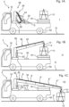
- Fig. 6A illustrates a schematic top view of a crane 2 according to the invention having a front end mounted lifting system 28, wherein Fig. 6B illustrates a schematic top view of a crane 2 according to the invention having a front end mounted lifting system 28.
- Both the crane 2 shown in Fig. 6A and in Fig. 6B is mounted on a lorry having ground-engaging wheels 52 and outrigger legs 44, 44', 46, 46'.
- the lifting system 28 comprises a jib 26 rotatably attached to a column.
- a first zone Z 1 is indicated. It can be seen that when the jib 26 is moved from the first configuration I to the second configuration II, the jib 26 is moved in a path P 1 indicated by a dotted line. In the first configuration II, the distance D 1 between the lifting system 28 (the distal portion of the jib 26) and the zone Z 1 is indicated. As this distance D 1 is larger than the required minimum length L 1 between the lifting system and the zone Z 1 , movement of the jib 26 along the shown path P 1 will not cause the control unit to stop the actuators causing the movement.
- the control unit of the crane would stop the actuator(s) (not shown) or cause the actuator(s) to reverse the motion.
- the distance D 1 may be detected by using any suitable means, e.g. by using sensors detecting the position and/or angle of the structures of the lifting system 28 including the jib 26 and/or sensors configured to determine the position of the zone Z 1 .
- a second zone Z 2 is illustrated. It can be seen that when the jib 26 is moved from the first configuration I to the second configuration II, the jib 26 is moved in a path P 2 indicated by a dotted line. In the first configuration II, the distance D 2 between the lifting system 28 (the distal portion of the jib 26) and the zone Z 2 is indicated. As this distance D 2 is larger than the required minimum length L 2 between the lifting system and the zone Z 2 , movement of the jib 26 along the shown path P 2 will not cause the control unit (not shown) to stop the actuators (not shown) causing the movement.
- Fig. 7A illustrates a view of a display of a user interface 32 according to the invention
- Fig. 7B illustrates a view of a display of another user interface 32 according to the invention.
- the user interface 32 shown in Fig. 7A comprises a left column, from which the operator can select a start position (configuration I).
- the user interface 32 shown in Fig. 7A moreover comprises a right column, from which the operator can select an end position (configuration II).
- the operator has selected "Position B36" as the first configuration I.
- “Position B36” may be a default start position or configuration.
- the operator has selected "Position E12" as the second configuration II.
- “Position E12” may be a default end position or configuration.
- the user interface 32 shows a map with a crane 2 positioned on the street next to a building 50.
- the operator can select the start configuration I and the end configuration II by using the user interface 32. It can be seen that the operator has selected an end configuration II on the flagstones outside the building 50. Accordingly, the crane 2 enables the operator to bring the load 12 carried by the jib of the crane 2 to move into a position in which the load 12 is delivered on the selected position (configuration II).
- the user interface 32 shown in Fig. 7A and in Fig. 7B comprises a start button 54, a pause button 54' and a stop button 54", that the operator can apply if desired.
- the use of any of these buttons 54, 54', 54" will "over rule” the control unit.
- Fig. 8 illustrates an operator 40 applying a user interface 32 according to the invention to control a crane 2 according to the invention.
- the crane 2 comprises a lifting system 28 comprising a column 6 and a jib 26 moveably attached to said column 6.
- the jib 26 comprises a displaceably mounted boom section 8.
- the lifting system 28 comprises actuators 22, 22', 24 arranged and configured to move structures of the lifting system 28 relative to each other.
- the operator 40 is capable of selecting a first configuration (start configuration of the crane 2) and a second configuration (end configuration of the crane 2) and initiate a control system (not shown) of the crane 2 to bring the lifting system 28 of the crane 2 from the first configuration to the second configuration.
- a hook 10 arranged in the distal end of the boom section 8 is attached to the sling of a load 12.
- the load 12 is arranged in a distance D 2 from a zone Z 2 surrounding a lamp that is fragile and thus cannot be brought into contact with either the load 12 or the lifting system 28.
- a predefined minimum “allowable" length L2 is indicated.
- the crane 2 is configured to prevent that the load 12 or the lifting system is brought into a distance D 2 that is equal to or shorter than L 2 . Accordingly, collision with the lamp can be avoided.
- Fig. 9B illustrates a view of a crane 2 according to the invention having a lifting system 28 arranged in a first configuration I
- Fig. 9B illustrates a view of the crane 2 shown in Fig. 9A , wherein the lifting system 28 is arranged in another configuration II.
- the crane 2 comprises a lifting system 28 comprising a crane base 4 and a column 6 rotatably attached thereto.
- a jib 26 is moveably attached to the column 6.
- the jib 26 comprises displaceably mounted boom sections 8, 8'.
- the lifting system 28 comprises actuators 22 arranged and configured to move structures of the lifting system 28 relative to each other.
- a hook 10 is arranged in the distal end of the outermost boom section 8'.
- a load 12 is carried by the crane 2. The load 12 is attached to the hook 10.
- the crane 2 comprises a cab 16 that may be defined as a zone from which the lifting system 28 and the load 12 carried by the lifting system 28 should be kept within a distance exceeding a predefined minimum level.
- the crane 2 is mounted in the front end of a truck bed of a lorry having wheels engaging the ground G.
- the crane 2 comprises a control unit 30 configured to receive control signals transmitted by a user interface 32 handled by an operator 40.
- the operator 40 can control the crane 2 by selecting a start configuration I and an end configuration II and make the crane 2 move the load 12 from the position shown in Fig. 9A to the position shown in Fig. 9B .
- Fig. 10A illustrates a view of a crane 2 according to the invention performing an automatic lifting task comprising the step of loading the truck bed 58 of a lorry.
- Fig. 10B illustrates the crane 2 shown in Fig. 10A , wherein the truck bed 58 has almost been loaded.
- the crane 2 basically corresponds to the crane explained with reference to Fig. 9A and Fig. 9B , however, the hook has been replaced by a fork 11 arranged to lift pallets 12' and load the truck bed 58 of the lorry.
- the pallets 12' are arranged in a stockpile 56 on the ground G next to the lorry.
- Fig. 10B a plurality of the pallets 12' have been moved from the stockpile 56 and are arranged on the truck bed 58 of the lorry.
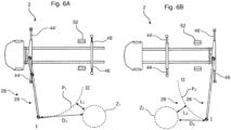
- Fig. 11A illustrates a view of a display of a user interface 32 according to the invention, wherein the user interface 32 allows the operator to select and perform an automatic loading process.
- Fig. 11B illustrates a view of the user interface 32 shown in Fig. 11A , when the loading process has been accomplished.
- the loading process includes loading pallets 12'.
- the pallets may by way of example contain a building material roof tile, bricks, flagstone.
- the size and geometry of the pallets is predetermined, it is possible to forecast where to arrange the pallets on the truck bed 58. Accordingly, it is possible to carry out an automatic loading process.
- the crane 2 comprises visual detection units (e.g. cameras and/or distance censors) arranged and configured to detect the position and/or orientation of the pallets 12' to be loaded on the truck bed 58.
- visual detection units e.g. cameras and/or distance censors
- the visual detection units are arranged and configured to detect the position and/or orientation of receiving areas 60, 60', 60" on the truck bed 58.
- the crane 2 comprises a control unit configured to receive and determine the position of receiving areas 60, 60', 60" of the truck bed 58.
- the position of receiving areas 60, 60', 60" of the truck bed 58 may be determined on the basis of knowledge of the size and geometry of the pallets 12' and the truck bed 58.
- Fig. 11A and Fig. 11B it can be seen that the truck bed 58 is divided into 24 receiving areas 60, 60', 60" indicated by dotted lines. These receiving areas 60, 60', 60" can each receive a pallet 12' of the stockpile 56.
- the user interface 32 is configured to allow the user to select the size and/or geometry of the load 12' to be carried, so that the control unit can process this information in order to calculate the size and position of the receiving areas 60, 60', 60".
- the pallets 12' were smaller than the one shown in Fig. 11A and Fig. 11B , the number of the receiving areas 60, 60', 60" may have been higher, whereas the size of the receiving areas 60, 60', 60" may have been smaller.
- the operator selects the option "Automatic load of 24 pallets" in the menu and presses the start button 54.
- the automatic loading process is initiated.
- the operator hereby defines the start configuration I, as to load pallets 12' from the stockpile 56 and the second configuration II, as to load the truck bed 58.
- the operator has the option of pausing the loading process by pressing the pause button 54' or stopping the loading process by pressing the stop button 54".
- Fig. 11B it can be seen that the user interface 32 reads "Task completed", which indicates that the truck bed 58 has been loaded with pallets 12'.
- Fig. 11A and Fig. 11B it can be seen that a plurality of pallets 12' have been removed from the stockpile 56 and that these pallets 12' have been arranged in the predefined receiving areas 60, 60', 60" of the truck bed 58.
Landscapes
- Engineering & Computer Science (AREA)
- Mechanical Engineering (AREA)
- Automation & Control Theory (AREA)
- Life Sciences & Earth Sciences (AREA)
- Agronomy & Crop Science (AREA)
- Jib Cranes (AREA)
Description
- The present invention relates to a crane and a method for operating a crane. More particularly, the invention relates to a method for operating a crane to perform a task automatically without manual assistance.
- The operation of cranes can be a complex and challenging task. Especially, when the operator has to avoid collision with objects that are difficult to strike during movement of the lifting system of the crane. Nowadays, manual control of the lifting structures is applied per default. Accordingly, control of a crane requires full attention of the operator throughout all steps of the lifting tasks.
-
WO2015001401A1 discloses a crane and a method of controlling a crane that comprises a lift system configured to be arranged in a plurality of configurations. The lifting system comprises a plurality of structures that are movably arranged relative to each other and actuator adapted to move the structures relative to each other. - In order to assist the operator and ease the operation of the crane, it would be desirable to provide a method and a crane that allows certain crane tasks to be carried out automatically by the crane.
-
WO2015113084A1 discloses a method for controlling a lorry crane according to the preamble ofclaim 1. The crane controller is configured to be operated in a first operating mode in which the crane can be freely operated by a user using control commands and in a second operating mode that can be activated by the user, in which the crane geometry is performed in a predetermined sequence of movements by the crane control is changeable. This solution, however, only provides a single fixed path determined at a single fixed initial position. -
CN201358142Y discloses an automatic control system for a telescopic boom. This solution, however, only provides a fixed path determined on the basis of manually selected starting position and a manually selected ending position. - Accordingly, it is desirable to be able to provide an improved controller and a method for controlling a crane in a more sophisticated manner.
- Thus, it is an object of the present invention to provide a method and a crane that allows certain crane tasks to be carried out by the crane automatically in a more sophisticated manner.
- The object of the present invention can be achieved by a method as defined in
claim 1 and by a crane having the features as defined in claim 9. - Preferred embodiments are defined in the dependent subclaims, explained in the following description and illustrated in the accompanying drawings.
- The method according to the invention is a method for controlling a lorry crane, having a lifting system configured to be arranged in a plurality of configurations, wherein the lifting system comprises a plurality of structures moveably arranged relative to each other and one or more actuators arranged to move the structures relative to each other, wherein the method comprises the following steps:
- selecting a first configuration among a plurality of configurations by means of a control system comprising an operable control unit;
- selecting a second configuration among a plurality of configurations by means of the control unit;
- activating the control unit to automatically bringing the lifting system from the first configuration into the second configuration by using one or more actuators,
- Hereby, it is possible to bring the lifting system of the crane automatically from the first configuration to the second configuration without any action required from the operator in a more sophisticated manner. The method is capable of continuously determining the most optimum path and automatically operate the crane accordingly. Moreover, the method makes it possible to operate a crane in a safer manner.
- The lifting system comprises a plurality of structures moveably arranged relative to each other. These structures may be a crane base, a column being rotatably attached to the crane base, a jib comprising a number of booms. In a preferred embodiment, the structures may comprise a plurality of booms displaceable arranged with respect to each other. The plurality of booms may preferably be arranged in a telescopical manner with respect to each other.
- The lifting system comprises one or more actuators arranged to move the structures relative to each other. The actuators may be of any suitable size and type. In a preferred embodiment, the actuators are formed as hydraulic cylinders.
- The method comprises the step of selecting a first configuration by means of a control system comprising an operable control unit.
- The method comprises the step of selecting a second configuration by means of the control unit.
- The first configuration and/or the second configuration may e.g. be selected from a predefined list or may be selected by any indication means e.g. by pointing out a position on a map on a user interface (e.g. a display). The first and/or second configurations may be positions (e.g. lifting positions of a load), it may alternatively be a configuration of a boom/crane arm such as an un-folded configuration of the boom/crane arm or a folded configuration of the boom/crane arm.
- The method comprises the step of activating the control unit to automatically bringing the lifting system from the first configuration into the second configuration by using one or more actuators.
- It may be an advantage that the first configuration and/or the second configuration is a position of a load being carried by the crane or a position of a structure of the lifting system. This means that the first configuration and/or the second configuration can be defined by the position, at which a load carried by the crane or to be carried by the crane is located.
- It may be beneficial that the first configuration and/or the second configuration are selected from a list being visibly available on a user interface. Hereby, the operator can easily select among predefined configurations. The list may include numbers and/or other text or symbols.
- In one embodiment, one configuration may be the lifting system in a folded configuration, in which the lifting system takes up less space than during lifting tasks.
- In another embodiment, one configuration may be the lifting system in an un-folded configuration, in which the lifting system is ready to lift a load (e.g. from a first position to another position).
- It may be advantageous that the method comprises the step of selecting the first configuration and/or the second configuration by indicating a position in a map displayed on a user interface or by using an external transmitter unit. Hereby, the selecting process is eased in a user-friendly manner. Furthermore, in some applications it allows the operator to get an overview over the surrounding.
- The method comprises the step of keeping the structures in positions, in which the distance between the structures and one or more zones and/or positions is larger than a predefined length. Hereby, it is possible to avoid collision between the lifting system and objects positioned in said zones or positions. Accordingly, the invention ensures that fragile objects are protected from impacts and contact with the lifting system. This is of major importance if a lorry crane carries fragile cargo that is not resistant to collision with the lifting system of the crane.
- The method is furthermore capable of protecting moving objects. The position of moving objects (e.g. a human, an animal or a vehicle) may be detected by any suitable detection units, e.g. visual sensors (e.g. cameras).
- It may be an advantage that the method comprises the step of automatically stopping the actuators when the distance between the structures and the one or more zones and/or positions is equal to or smaller than the predefined length. Hereby, it is possible to control the crane in a safe manner, in which collision with objects can be prevented. It is by way of example possible to predefine the cab of a lorry to be a "safe zone", wherein the lifting system is required to be provided within a predefined minimum distance to the safe zone.
- It may be beneficial that the method comprises the step of automatically reducing the rotational and/or linear speed of one or more of the structures of the lifting system when the distance between the structures and the one or more zones and/or positions is equal to or smaller than the predefined length. Reducing the speed may be accomplished by controlling one or more of the actuators. Hereby, it is possible to control the crane in an even more safe manner, because the speed of structures of the lifting system can be reduced when the structures approach predefined positions or zones.
- It may be advantageous that the method comprises the step of detecting one or more zones and/or positions by using one or more sensors.
- It may be beneficial that the zones and/or positions are predefined or are set by default or set by the user/operator of the crane.
- It may be advantageous that the one or the one or more sensors is a camera, an ultrasonic sensor, a proximity sensor or an optic distance sensor.
- By using one or more cameras, it is possible to visually detect e.g. moving objects and optionally carry out processing in order to determine if the object is a critical object so that the lifting system should be stopped or if the moving object is out of the critical range of the lifting system (e.g. a dog running away from the crane). It may be an advantage that the method comprises the step of carrying out calculations in order to recognise one or more detected objects in order to make decisions according to a predefined scheme.
- By using an ultrasonic sensor, it is possible to detect the distance to one or more objects.
- By using a proximity sensor, it is possible to detect if an object is within a predefined range from a predefined area (e.g. a structure of the lifting system).
- By using an optic distance sensor, it is possible to detect one or more distances optically.
- It may be an advantage that the control unit comprises an object recognition unit configured to recognise one or more objects of predefined size and/or geometry and/or speed based on data provided by means of a camera. Hereby, it is possible to recognise one or more objects and take this into account e.g. in order to stop the movement of the lifting system or to move the lifting system away from the object in order to avoid collision. The objects may be moving objects such as a human or an animal. The objects may also be a vehicle such as a car, a bicycle or a motorcycle.
- The method comprises the step of detecting the length of a structure of the lifting system and/or an angular position of a structure of the lifting system, wherein the control unit applies the length of a structure and/or the angular position of a structure to calculate a path, through which path the control unit brings the lifting system from the first configuration into the second configuration by using one or more actuators. Due to the constrains in the lifting system, detection of the length and angles of the structures of the lifting system will provide information sufficient to calculate one or more possible paths through which the lifting system can be brought from the first configuration into the second configuration by using one or more actuators.
- The term "angular position" may include an angle between adjacent structures or an angle of a structure relative to a predefined orientation (e.g. vertical or horizontal).
- It may be an advantage that the method comprises the step of regulating the speed (translation and rotation) of the structures in dependency of the distance between the structures and the one or more zones and/or positions.
- The crane according to the invention is a lorry crane that comprises a lifting system configured to be arranged in a plurality of configurations, wherein the lifting system comprises:
- a plurality of structures moveably arranged relative to each other;
- one or more actuators arranged to move the structures relative to each other,
- select a first configuration among a plurality of configurations;
- select a second configuration among a plurality of configurations and
- activate the control unit to automatically bringing the lifting system from the first configuration into the second configuration by using one or more actuators, wherein the control unit is configured to detect the length of a structure of the lifting system and/or an angular position a structure of the lifting system by means of one or more sensors, wherein the control unit is configured to apply the length of a structure and/or the angular position of a structure to calculate a path through which the control unit brings the lifting system from the first configuration into the second configuration by using one or more actuators, wherein the path is determined continuously during the operation of the lifting system, wherein the control system is configured for keeping the structures in positions, in which the distance between the structures and one or more zones and/or positions is larger than a predefined length.
- Hereby, it is possible to bring the lifting system of the crane automatically from the first configuration to the second configuration without any action required from the operator in a safer manner. The crane is capable of continuously determining the most optimum path and automatically operate the crane accordingly.
- The lifting system comprises a plurality of structures moveably arranged relative to each other. These structures may be a crane base, a column being rotatably attached to the crane base, a jib comprising a number of booms. In a preferred embodiment, the structures may comprise a plurality of booms displaceably arranged with respect to each other. The plurality of booms may preferably be arranged in a telescopically manner with respect to each other.
- The lifting system comprises one or more actuators arranged to move the structures relative to each other. The actuators may be of any suitable size and type. In a preferred embodiment, the actuators are formed as hydraulic cylinders.
- The control unit enables the operator to select a first configuration by means of the control system comprising the operable control unit.
- The first configuration and/or the second configuration may e.g. be selected from a predefined list or may be selected by any indication means e.g. by pointing out a position on a map on a user interface (e.g. a display). The first and/or second configurations may be positions (e.g. lifting positions of a load), it may alternatively be a configuration of a boom/crane arm such as an un-folded configuration of the boom/crane arm or a folded configuration of the boom/crane arm.
- It may be an advantage that the first configuration and/or the second configuration is a position of a load being carried by the crane or a position of a structure of the lifting system. This means that the first configuration and/or the second configuration can be defined by the position, at which a load carried by the crane or to be carried by the crane is located.
- It may be beneficial that the first configuration and/or the second configuration are selected from a list being visibly available on a user interface. Hereby, the operator can easily select among predefined configurations.
- It may be an advantage that the first configuration and/or the second configuration is a position of a load being carried by the crane or a position of a structure of the lifting system. The position may be defined in any suitable coordinate system, e.g. a Cartesian coordinate system, a spherical coordinate system or a polar coordinate system.
- It may be advantageous that the crane comprises a user interface, by which it is possible to select the first configuration and/or the second configuration. The use of a user interface makes it easier for the operator to select the configurations.
- In one embodiment, the user interface is configured to allow the user to select a first configuration and a second configuration and a third configuration (that may correspond to the first configuration).
- It may be an advantage that the crane comprises a user interface configured to visually display a map, by which it is possible to select the first configuration and/or the second configuration. Hereby, it is possible to make the crane user-friendly. The map may be a one-dimensional map or preferably a two-dimensional map or a three-dimensional map.
- It may be an advantage that the control system comprises one or more sensors arranged and configured to detect the distance between the structures and one or more zones and/or positions. Hereby, the distance between the structures and one or more zones and/or positions can be detected.
- It may be beneficial that the control system is configured to detect when the distance between the structures and the one or more zones and/or positions is larger than a predefined length.
- It may be an advantage that the control unit is configured to automatically stop the actuators when the distance between the structures and one or more zones and/or positions is equal to or smaller than the predefined length. Hereby, the crane can carry out movements of the lifting system and automatically avoid collisions with predefined objects positioned in predefined positions or zones.
- The zones and/or positions may be predefined if they are set by default or set by the user/operator of the crane.
- The one or the one or more sensors may be a camera, an ultrasonic sensor, a proximity sensor or an optic distance sensor.
- It may be advantageous that the control unit comprises an object recognition unit configured to recognise one or more objects of predefined size and/or geometry and/or speed based on data provided by means of a camera. The object recognition unit may comprise a computer-implemented system that may be configurable.
- The objects may be moving objects such as a human, an animal or a vehicle.
- The control unit is configured to detect the length of a structure of the lifting system and/or an angular position of a structure of the lifting system by means of one or more sensors, wherein the control unit is configured to apply the length of a structure and/or the angular position of a structure to calculate a path, through which the control unit brings the lifting system from the first configuration into the second configuration by using one or more actuators. Hereby, the sensors can provide information sufficient to make sure that all positions of the lifting system are known. Put in other words, the position of the lifting system will be known on a continuous basis.
- The path is determined continuously during the operation of the lifting system. Hereby, it is possible to change the path if this is suitable, e.g. if a moving object is determined or if the control unit determines that another path is desirable. It may be an advantage that the control unit is configured to on a continuous basis look for the most optimum path based on at least one predefined criterion.
- The sensors for detecting the length of a structure of the lifting system and/or an angular position of a structure of the lifting system may be any suitable type of sensors including angle sensors and distance sensors.
- The term "angular position" may include the angle between adjacent structures and the angle of a structure relative of a predefined orientation (e.g. a vertical or a horizontal axis).
- It may be an advantage that the crane is configured to regulate the speed (translation and rotation) of the structures in dependency of the distance between the structures and the one or more zones and/or positions. This may be done by using the control unit of the crane.
- A system according to the invention comprises a lorry crane, an external transmitter unit and a receiving unit, wherein the transmitter unit is configured to transmit its position information to the receiving unit.
- Hereby, the external transmitter unit can be positioned in a desirable position (e.g. on the ground at an area in which a cargo has to be delivered) and the position of the external transmitter unit can be detected by the receiving unit so that the position of the external transmitter unit can be used as a setting in the control unit. Accordingly, the crane can deliver the cargo in the right position by selecting the said position as the "second configuration of the lifting system".
- In one embodiment, the crane comprises a control unit configured to control the lifting system of the crane in such a manner that the crane can perform an automatic loading process that includes loading of a plurality of objects/loads into a predefined area.
- In one embodiment, the crane comprises a control unit configured to control the lifting system of the crane in such a manner that the crane can load a truck bed with objects/loads from a stockpile (e.g. on the ground).
- In another embodiment, the crane comprises a control unit configured to control the lifting system of the crane in such a manner that the crane can unload a truck bed and place the objects/loads from the truck bed to a predefined area (e.g. a stockpile on the ground).
- In one embodiment, the crane comprises a user interface configured to display a setup that allows the operator to select and perform an automatic loading process.
- It may be an advantage that the crane comprises visual detection units (e.g. cameras and/or distance censors) arranged and configured to detect the position and/or orientation of objects/loads to be loaded and/or unloaded (e.g. to a truck bed of a lorry crane). Hereby, it is possible to automatically position the lifting system of the crane in the correct position in order to lift the objects/loads (e.g. pallets) from their initial position (e.g. in a stockpile). This may be visually illustrated by using a user interface.
- It may be beneficial that the crane comprises visual detection units (e.g. cameras and/or distance censors) that are arranged and configured to detect the position and/or orientation of receiving areas (e.g. of the truck bed or an area on the ground). It is preferred that the crane comprises a control unit configured to receive and determine the position of receiving areas.
- The position of receiving areas may be determined on the basis of knowledge of the size and geometry of the objects/loads and area into which the objects/loads have to be placed.
- It may be beneficial that the crane comprises a user interface configured to allow the user to select the size and/or geometry of the objects/loads to be carried, so that the control unit can process this information in order to calculate the size and position of the receiving areas.
- The invention will become more fully understood from the detailed description given herein below. The accompanying drawings are given by way of illustration only, and thus, they are not limitative of the present invention. In the accompanying drawings:
- Fig. 1A
- shows a side view of a crane according to the invention having a lifting system arranged in a first configuration;
- Fig. 1B
- shows a side view of the crane shown in
Fig. 1A , wherein the lifting system is arranged in a second configuration; - Fig. 1C
- shows a side view of the crane shown in
Fig. 1A , wherein the lifting system is arranged in a third configuration; - Fig. 2A
- shows a view of a crane according to the invention having a lifting system arranged in a first configuration;
- Fig. 2B
- shows a side view of the crane shown in
Fig. 2A , wherein the lifting system is arranged in a second configuration; - Fig. 2C
- shows a side view of the crane shown in
Fig. 2A , wherein the lifting system is arranged in a third configuration; - Fig. 3A
- shows a view of a crane according to the invention having a lifting system arranged in a first configuration;
- Fig. 3B
- shows a side view of the crane shown in
Fig. 3A , wherein the lifting system is arranged in a second configuration; - Fig. 3C
- shows a side view of the crane shown in
Fig. 3A , wherein the lifting system is arranged in a third configuration; - Fig. 3D
- shows a side view of the crane shown in
Fig. 3A , wherein the - Fig. 4
- lifting system is arranged in a fourth configuration; shows a view of a lifting system of a crane according to the invention and a moving object passing by;
- Fig. 5
- shows a crane according to the invention and a transmitter unit used to detect the position, in which a load has to be positioned;
- Fig. 6A
- shows a schematic top view of a crane according to the invention having a front end mounted lifting system;
- Fig. 6B
- shows a schematic top view of a crane according to the invention having a front end mounted lifting system;
- Fig. 7A
- shows a view of a display of a user interface according to the invention;
- Fig. 7B
- shows a view of a display of another user interface according to the invention;
- Fig. 8
- shows an operator applying a user interface according to the invention to control a crane according to the invention;
- Fig. 9A
- shows a view of a crane according to the invention having a lifting system arranged in a first configuration;
- Fig. 9B
- shows a view of the crane shown in
Fig. 9A , wherein the lifting system is arranged in another configuration; - Fig. 10A
- shows a view of a crane according to the invention performing an automatic lifting task comprising the step of loading the truck bed of a lorry;
- Fig. 10B
- shows the crane shown in
Fig. 10A , wherein the truck bed has almost been loaded; - Fig. 11A
- shows a view of a display of a user interface according to the invention, wherein the user interface allows the operator to select and perform an automatic loading process and
- Fig. 11B
- shows a view of the user interface shown in
Fig. 11A , when the loading process has been accomplished. - Referring now in detail to the drawings for the purpose of illustrating preferred embodiments of the present invention, a
crane 2 of the present invention is illustrated inFig. 1A . -
Fig. 1A illustrates a side view of acrane 2 according to the invention comprising alifting system 28 arranged in a first configuration I.Fig. 1B illustrates a side view of thecrane 2 shown inFig. 1A , wherein thelifting system 28 is arranged in a second configuration II, whereasFig. 1C illustrates a side view of thecrane 2 shown inFig. 1A , wherein thelifting system 28 is arranged in a third configuration III. - The
crane 2 is arranged on a lorry comprising acab 16 and a truck bed configured to receive and transport objects as theload 12 that is arranged on thecargo 18 positioned in the rear side of the truck bed. Afragile member 20 is arranged in the central portion of the track bed of the lorry. InFig. 1A , a zone Z1 showing an area within a predefined distance to thefragile member 20 is indicated. The distance D1 from the liftingsystem 28 to the zone Z1 is shown. In a preferred embodiment, the invention makes it possible to define the zone Z1 in such a manner that the structures of thelifting system 28 are kept in positions, in which the distance D1 between the structures and the zone Z1 is larger than a predefined length L1. The lorry is arranged on the ground G by means of its ground-engagingwheels 52. - The
crane 2 comprises alifting system 28 arranged in a first configuration. Thelifting system 28 comprises acrane base 4 fixed to the truck bed, acolumn 6 protruding from thecrane base 4 and ajib 26 rotatably attached to thecolumn 6. - The
lifting system 28 comprises an actuator (a hydraulic cylinder) 22 arranged and configured to rotate thejib 26 relative to thecolumn 6. Thejib 26 comprises a plurality of telescopicdisplaceable booms sections displaceable booms sections hydraulic actuators 24 extending along the longitudinal axis of thebooms sections hook 10 is arranged at the distal end of thedistal boom section 8"". InFig. 1B and Fig. 1C , thehook 10 holds asling 14 fixed to theload 12. Thecrane 2 moves theload 12 from its initial position on the top of the cargo 18 (seeFig. 1B ) to the ground G (seeFig. 1C ). - In
Fig. 1A , the lifting system is arranged in a folded configuration. InFig. 1B , thelifting system 28 has been partly unfolded and thehydraulic actuator 22 has increased the angle between thecolumn 6 and thejib 26. Moreover, the boom of thejib 26 has been partly extended in order to align thehook 10 at the top of thesling 14. InFig. 1C , thejib 26 has been extended further by means of thehydraulic actuators 24. Furthermore, the angle between thecolumn 6 and thejib 26 has been decreased by using thehydraulic actuator 22. - The
crane 2 according to the invention is configured to control and bring thelifting system 28 from a first configuration to a second configuration. This is accomplished by selecting a first configuration and a second configuration by means of a control system comprising an operable control unit (seeFig. 7A, Fig. 7B ,Fig. 8 ,Fig. 9A and Fig, 9B ). The control unit is configured to initiate that theactuators lifting system 28 from the first configuration (e.g. the figuration arranged inFig. 1A ) into the second configuration (e.g. the figuration arranged inFig. 1B ) by using one or more of theactuators lifting system 28 from the first configuration to the second configuration automatically without any manual input required. In one embodiment, the crane is configured to bring thelifting system 28 from an un-folded configuration (as shown inFig. 1A ) to a predefined second configuration. In another embodiment, the crane is configured to bring thelifting system 28 from a first configuration to the un-folded configuration (as shown inFig. 1A ). - In a preferred embodiment, the
crane 2 is configured to bring thelifting system 26 from a first selected configuration to a second selected configuration in a manner in which thelifting system 28 avoids collision with one or more predefined areas or objects (e.g. the fragile member 20). In a preferred embodiment, thecrane 2 comprises a control unit configured to select one or more areas or objects that thelifting system 28 and theload 12 carried by it should be kept in a distance from (in order to prevent collision). -
Fig. 2A illustrates a view of acrane 2 according to the invention having a liftingsystem 28 arranged in a first configuration I.Fig. 2B illustrates a side view of thecrane 2 shown inFig. 2A , wherein thelifting system 28 is arranged in a second configuration II.Fig. 2C illustrates a side view of thecrane 2 shown inFig. 2A , wherein thelifting system 28 is arranged in a third configuration III. - The
crane 2 is mounted on the rear side of a lorry having acab 16. A zone Z1 surrounding thecab 16 is indicated. The zone Z1 represents a safety zone, from which thelifting system 28 should be kept in a distance exceeding a predefined level so that collision with thecab 16 can be avoided. A zone Z2 surrounding afragile member 20 arranged on the truck bed is indicated. This zone Z2 represents an area, from which thelifting system 28 should be kept in a distance exceeding a predefined level so that collision with thefragile member 20 can be avoided. Thecrane 2 comprises a control system (not show) comprising an operable control unit (not shown), by which it is possible to define the position and extension (volume or area) of the zones Z1, Z2. The control unit further is configured to be used to define one or more predefined lengths, wherein the control unit controls theactuators lifting system 28 are kept in positions in which the distance between said structures and the zones Z1, Z2 is larger than the predefined length(s). Hereby, it is possible to avoid collision between the liftingsystem 28 and objects 16, 20 positioned in said zones Z1, Z2. Accordingly, thecrane 2 ensures thatfragile objects lifting system 28. Thecrane 2 comprisesoutrigger legs 44, 44' arranged to increase the stability (and decrease the risk for tipping) of thecrane 2. - The
crane 2 comprises alifting system 28 configured to be arranged in a plurality of configurations I, II, III. Thelifting system 28 comprises a plurality of structures: abase 4, acolumn 6 and ajib 26 comprising a plurality of slidably arrangedbooms actuators crane 2 is configured to select a first configuration I by means of the control system comprising the operable control unit, select a second configuration II by means of the control unit and activate the control unit to automatically bring thelifting system 28 from the first configuration I into the second configuration II or from the second configuration II to the third configuration III by using theactuators crane 2 makes it possible for the operator to let thecrane 2 carry out selected crane tasks automatically. -
Fig. 3A illustrates a view of a portion of acrane 2 according to the invention having a liftingsystem 28 arranged in a first configuration I.Fig. 3B illustrates a side view of thecrane 2 shown inFig. 3A , wherein thelifting system 28 is arranged in a second configuration II.Fig. 3C illustrates a side view of thecrane 2 shown inFig. 3A , wherein thelifting system 28 is arranged in a third configuration III andFig. 3D illustrates a side view of thecrane 2 shown inFig. 3A , wherein thelifting system 28 is arranged in a fourth configuration IV. - The
crane 2 is brought from an unfolded configuration I into a folded configuration IV during the steps shown inFig. 3A to Fig. 3D . Thecrane 2 comprises a lifting system comprising ajib 26 rotatably attached to acolumn 6 that is rotatably attached to acrane base 4. Thecrane 2 comprisesactuators lifting system 28 relative to each other. Ahook 10 is arranged in the distal end of the outermost boom of thejib 26. - In a preferred embodiment, the
crane 2 and method for controlling thecrane 2 is configured to bring thelifting system 28 into the folded configuration IV shown inFig. 3D . This may be done when thelifting system 28 is arranged in the first configuration I as shown inFig. 3A , when thelifting system 28 is arranged in the second configuration II as shown inFig. 3A or when thelifting system 28 is arranged in the third configuration III as shown inFig. 3C . Hereby, the operator can automatically (without any required operator control action) bring thelifting system 28 into the folded configuration IV shown inFig. 3D in a simple and user-friendly manner. Besides, collision with objects can automatically be avoided. - The
crane 2 and the method for controlling thecrane 2 may preferably be configured to automatically bring thelifting system 28 from into any of the configurations I, II, III, IV to any of the configurations I, II, III, IV shown inFig. 3A, Fig. 3B, Fig. 3C or Fig. 3D . -
Fig. 4 illustrates a view of alifting system 28 of acrane 2 according to the invention and a movingobject 36 passing by. The moving object is a runningman 36. Thelifting system 28 of thecrane 2 comprises ajib 26 comprising booms slidably arranged with respect to each other. Thejib 26 is rotatably attached to acolumn 6. Thelifting system 28 comprises a number ofactuators lifting system 28 relative to each other. - A plurality of
cameras jib 26. Thecameras man 36. In a preferred embodiment, thecrane 2 comprises a control unit (not shown) comprising an object recognition unit (not shown) configured to recognise one ormore objects 36 of predefined size and/or geometry and/or speed based on data provided by means of one or more of thecameras lifting system 28. Furthermore, it may be predefined that objects moving with a speed exceeding a predefined level should cause the actuators to stop or move the structures of thelifting system 28 in another direction in order to avoid collision with the object. - In a preferred embodiment, the
crane 2 comprises a control unit configured to stop or move the structures of thelifting system 28 in another direction in order to avoid collision with theobject 36 by using theactuators lifting system 28 or aload 12 carried by the liftingsystem 28 is equal to or below a predefined length L1 as illustrated. Hereby, it is possible to avoid collision with theobject 36. - The
first camera 34 arranged in the distal end of thejib 26 receives detected signals 38 indicated with dotted lines. Likewise, two of theother cameras 34", 34‴ receives detected signals 38", 38"'. -
Fig. 5 illustrates acrane 2 according to the invention and atransmitter unit 42 used to detect the position, in which aload 12 has to be positioned. Thecrane 2 comprises a front-mountedlifting system 28 provided on alorry comprising wheels 52 arranged on the ground. Thecrane 2 comprises alifting system 28 comprising acrane base 4, acolumn 6 rotatably attached to thecrane base 4 and ajib 26 rotatably attached to thecolumn 6. Thejib 26 comprises a plurality of booms telescopically arranged with respect to each other. Thelifting system 28 comprises ahydraulic actuator 22 arranged to rotate thejib 26 relative to thecolumn 6 and another actuator 22' arranged to rotate structures of thejib 26 relative to each other. Thejib 26 moreover comprises ahydraulic actuator 24 arranged to displace the telescopically arranged booms with respect to each other. - The lorry comprises a
cab 16 that may be selected as a safe zone as default in a preferred embodiment in order to avoid collision of the liftingstructure 28 and loads 12 carried by the liftingstructure 28 with thecab 16. - The
jib 26 comprises ahook 10 mounted in its distal end. Thehook 10 carries aload 12. Thetransmitter unit 42 is arranged at the end of a rod. Thetransmitter unit 42 transmits signals that are received by a receiving unit 48 connected to thecontrol unit 30 of thecrane 2. Accordingly, thetransmitter unit 42 can be used to determine the position of thetransmitter unit 42 in order to select the place of delivery. By using the control unit, it is possible to deliver theload 12 in the position marked by means of thetransmitter unit 42. -
Fig. 6A illustrates a schematic top view of acrane 2 according to the invention having a front end mounted liftingsystem 28, whereinFig. 6B illustrates a schematic top view of acrane 2 according to the invention having a front end mounted liftingsystem 28. Both thecrane 2 shown inFig. 6A and inFig. 6B is mounted on a lorry having ground-engagingwheels 52 andoutrigger legs lifting system 28 comprises ajib 26 rotatably attached to a column. - In
Fig. 6A , a first zone Z1 is indicated. It can be seen that when thejib 26 is moved from the first configuration I to the second configuration II, thejib 26 is moved in a path P1 indicated by a dotted line. In the first configuration II, the distance D1 between the lifting system 28 (the distal portion of the jib 26) and the zone Z1 is indicated. As this distance D1 is larger than the required minimum length L1 between the lifting system and the zone Z1, movement of thejib 26 along the shown path P1 will not cause the control unit to stop the actuators causing the movement. However, if the distance D1 would be equal to or smaller than the required minimum length L1, the control unit of the crane would stop the actuator(s) (not shown) or cause the actuator(s) to reverse the motion. The distance D1 may be detected by using any suitable means, e.g. by using sensors detecting the position and/or angle of the structures of thelifting system 28 including thejib 26 and/or sensors configured to determine the position of the zone Z1. - In
Fig. 6B , a second zone Z2 is illustrated. It can be seen that when thejib 26 is moved from the first configuration I to the second configuration II, thejib 26 is moved in a path P2 indicated by a dotted line. In the first configuration II, the distance D2 between the lifting system 28 (the distal portion of the jib 26) and the zone Z2 is indicated. As this distance D2 is larger than the required minimum length L2 between the lifting system and the zone Z2, movement of thejib 26 along the shown path P2 will not cause the control unit (not shown) to stop the actuators (not shown) causing the movement. -
Fig. 7A illustrates a view of a display of auser interface 32 according to the invention, whereasFig. 7B illustrates a view of a display of anotheruser interface 32 according to the invention. - The
user interface 32 shown inFig. 7A comprises a left column, from which the operator can select a start position (configuration I). Theuser interface 32 shown inFig. 7A moreover comprises a right column, from which the operator can select an end position (configuration II). The operator has selected "Position B36" as the first configuration I. "Position B36" may be a default start position or configuration. The operator has selected "Position E12" as the second configuration II. "Position E12" may be a default end position or configuration. - In
Fig. 7B , theuser interface 32 shows a map with acrane 2 positioned on the street next to abuilding 50. The operator can select the start configuration I and the end configuration II by using theuser interface 32. It can be seen that the operator has selected an end configuration II on the flagstones outside thebuilding 50. Accordingly, thecrane 2 enables the operator to bring theload 12 carried by the jib of thecrane 2 to move into a position in which theload 12 is delivered on the selected position (configuration II). - The
user interface 32 shown inFig. 7A and inFig. 7B comprises astart button 54, a pause button 54' and astop button 54", that the operator can apply if desired. In a preferred embodiment, the use of any of thesebuttons -
Fig. 8 illustrates anoperator 40 applying auser interface 32 according to the invention to control acrane 2 according to the invention. Thecrane 2 comprises alifting system 28 comprising acolumn 6 and ajib 26 moveably attached to saidcolumn 6. Thejib 26 comprises a displaceablymounted boom section 8. Thelifting system 28 comprisesactuators lifting system 28 relative to each other. - By using the
user interface 32, theoperator 40 is capable of selecting a first configuration (start configuration of the crane 2) and a second configuration (end configuration of the crane 2) and initiate a control system (not shown) of thecrane 2 to bring thelifting system 28 of thecrane 2 from the first configuration to the second configuration. Ahook 10 arranged in the distal end of theboom section 8 is attached to the sling of aload 12. Theload 12 is arranged in a distance D2 from a zone Z2 surrounding a lamp that is fragile and thus cannot be brought into contact with either theload 12 or thelifting system 28. A predefined minimum "allowable" length L2 is indicated. Thecrane 2 is configured to prevent that theload 12 or the lifting system is brought into a distance D2 that is equal to or shorter than L2. Accordingly, collision with the lamp can be avoided. -
Fig. 9B illustrates a view of acrane 2 according to the invention having a liftingsystem 28 arranged in a first configuration I, whereasFig. 9B illustrates a view of thecrane 2 shown inFig. 9A , wherein thelifting system 28 is arranged in another configuration II. - The
crane 2 comprises alifting system 28 comprising acrane base 4 and acolumn 6 rotatably attached thereto. Ajib 26 is moveably attached to thecolumn 6. Thejib 26 comprises displaceably mountedboom sections 8, 8'. Thelifting system 28 comprisesactuators 22 arranged and configured to move structures of thelifting system 28 relative to each other. Ahook 10 is arranged in the distal end of the outermost boom section 8'. Aload 12 is carried by thecrane 2. Theload 12 is attached to thehook 10. - The
crane 2 comprises acab 16 that may be defined as a zone from which thelifting system 28 and theload 12 carried by the liftingsystem 28 should be kept within a distance exceeding a predefined minimum level. Thecrane 2 is mounted in the front end of a truck bed of a lorry having wheels engaging the ground G. - The
crane 2 comprises acontrol unit 30 configured to receive control signals transmitted by auser interface 32 handled by anoperator 40. Hereby, theoperator 40 can control thecrane 2 by selecting a start configuration I and an end configuration II and make thecrane 2 move theload 12 from the position shown inFig. 9A to the position shown inFig. 9B . -
Fig. 10A illustrates a view of acrane 2 according to the invention performing an automatic lifting task comprising the step of loading thetruck bed 58 of a lorry.Fig. 10B illustrates thecrane 2 shown inFig. 10A , wherein thetruck bed 58 has almost been loaded. Thecrane 2 basically corresponds to the crane explained with reference toFig. 9A and Fig. 9B , however, the hook has been replaced by afork 11 arranged to lift pallets 12' and load thetruck bed 58 of the lorry. InFig. 10A , the pallets 12' are arranged in astockpile 56 on the ground G next to the lorry. InFig. 10B , a plurality of the pallets 12' have been moved from thestockpile 56 and are arranged on thetruck bed 58 of the lorry. -
Fig. 11A illustrates a view of a display of auser interface 32 according to the invention, wherein theuser interface 32 allows the operator to select and perform an automatic loading process.Fig. 11B illustrates a view of theuser interface 32 shown inFig. 11A , when the loading process has been accomplished. - The loading process includes loading pallets 12'. The pallets may by way of example contain a building material roof tile, bricks, flagstone. In case the size and geometry of the pallets is predetermined, it is possible to forecast where to arrange the pallets on the
truck bed 58. Accordingly, it is possible to carry out an automatic loading process. - In a preferred embodiment, the
crane 2 comprises visual detection units (e.g. cameras and/or distance censors) arranged and configured to detect the position and/or orientation of the pallets 12' to be loaded on thetruck bed 58. Hereby, it is possible to automatically position the lifting system of thecrane 2 in the correct position in order to lift the pallets from their initial position in astockpile 56 as indicated in theuser interface 32. Moreover, it is preferred that the visual detection units (e.g. cameras and/or distance censors) are arranged and configured to detect the position and/or orientation of receivingareas truck bed 58. It is preferred that thecrane 2 comprises a control unit configured to receive and determine the position of receivingareas truck bed 58. The position of receivingareas truck bed 58 may be determined on the basis of knowledge of the size and geometry of the pallets 12' and thetruck bed 58. InFig. 11A and Fig. 11B , it can be seen that thetruck bed 58 is divided into 24 receivingareas areas stockpile 56. - It is preferred that the
user interface 32 is configured to allow the user to select the size and/or geometry of the load 12' to be carried, so that the control unit can process this information in order to calculate the size and position of the receivingareas Fig. 11A and Fig. 11B , the number of the receivingareas areas - The operator selects the option "Automatic load of 24 pallets" in the menu and presses the
start button 54. Hereafter, the automatic loading process is initiated. The operator hereby defines the start configuration I, as to load pallets 12' from thestockpile 56 and the second configuration II, as to load thetruck bed 58. - The operator has the option of pausing the loading process by pressing the pause button 54' or stopping the loading process by pressing the
stop button 54". - In
Fig. 11B , it can be seen that theuser interface 32 reads "Task completed", which indicates that thetruck bed 58 has been loaded with pallets 12'. When comparingFig. 11A and Fig. 11B , it can be seen that a plurality of pallets 12' have been removed from thestockpile 56 and that these pallets 12' have been arranged in thepredefined receiving areas truck bed 58. -
- 2
- Crane
- 4
- Crane base
- 6
- Column
- 8, 8', 8", 8‴, 8""
- Boom section
- 10
- Hook
- 11
- Fork
- 12, 12'
- Load
- 14
- Sling
- 16
- Cab
- 18
- Cargo
- 20
- Fragile member
- 22, 22'
- Actuator
- 24
- Actuator
- 26
- Jib
- 28
- Lifting system
- 30
- Control unit
- 32
- User interface
- 34, 34', 34", 34‴
- Camera
- 36
- Moving object
- 38, 38", 38‴
- Detected signal
- 40
- Operator
- 42
- Transmitter unit
- 44, 44', 46, 46'
- Outrigger leg
- 48
- Receiving unit
- 50
- Building
- 52
- Wheel
- 54, 54', 54"
- Button
- 56
- Stockpile (e.g. brick stockpile)
- 58
- Truck bed
- 60, 60', 60"
- Receiving area
- G
- Ground
- D1, D2
- Distance
- L1, L2
- Length
- Z1, Z2
- Zone
- I, II, III, IV
- Configuration
- P1, P2
- Path
Claims (15)
- A method for controlling a lorry crane (2), having a lifting system (28) configured to be arranged in a plurality of configurations (I, II, III), wherein the lifting system (28) comprises a plurality of structures (6, 10, 22, 24, 26) moveably arranged relative to each other and one or more actuators (22, 24) arranged to move the structures (6, 10, 22, 24, 26) relative to each other, wherein the method comprises the following steps:- selecting a first configuration (I) among a plurality of configurations by means of a control system comprising an operable control unit (30);- selecting a second configuration (II) among a plurality of configurations by means of the control unit (30);- activating the control unit (30) to automatically bringing the lifting system (28) from the first configuration (I) into the second configuration (II) by using one or more actuators (22, 24),characterised in thatthe method comprises the step of detecting the length of a structure (6, 10, 22, 24, 26) of the lifting system (28) and/or an angular position of a structure (6, 10, 22, 24, 26) of the lifting system (28), wherein the control unit (30) applies the length of a structure (6, 10, 22, 24, 26) and/or the angular position a structure (6, 10, 22, 24, 26) to calculate a path (P1, P2), through which path (P1, P2) the control unit (30) brings the lifting system (28) from the first configuration (I) into the second configuration (II) by using one or more actuators (22, 24), wherein the path (P1, P2) is determined continuously during the operation of the lifting system,wherein the method comprises the step of keeping the structures (6, 10, 22, 24, 26) in positions, in which the distance (D1, D2) between the structures (6, 10, 22, 24, 26) and one or more zones (Z1, Z2) and/or positions is larger than a predefined length (L1, L2, L3).
- A method according to claim 1, characterised in that the first configuration (I) and/or the second configuration (II) is a position of a load (12) being carried by the crane (2) or a position of a structure (6, 10, 22, 24, 26) of the lifting system (28).
- A method according to claim 1 or 2, characterised in that the first configuration (I) and/or the second configuration (II) are selected from a list being visibly available on a user interface (32).
- A method according to claim 1 or 2, characterised in that the method comprises the step of selecting the first configuration (I) and/or the second configuration (II) by indicating a position in a map displayed on a user interface (32) or by using an external transmitter unit (42).
- A method according to one of the preceding claims, characterised in that the method comprises the step of automatically stopping the actuators (22, 24) when the distance (D1, D2) between the structures (6, 10, 22, 24, 26) and the one or more zones (Z1, Z2) and/or positions is equal to or smaller than the predefined length (L1, L2).
- A method according to one of the preceding claims, characterised in that the one or more zones (Z1, Z2) and/or positions are predefined or detected by using one or more sensors.
- A method according to claim 6, characterised in that the one or the one or more sensors is a camera (34, 34', 34", 34‴), an ultrasonic sensor, a proximity sensor or an optic distance sensor.
- A method according to claim 7, characterised in that the control unit (30) comprises an object recognition unit configured to recognise one or more objects of predefined size and/or geometry and/or speed based on data provided by means of a camera (34, 34', 34", 34"').
- A lorry crane (2) comprising a lifting system (28) configured to be arranged in a plurality of configurations (I, II, III), wherein the lifting system (28) comprises:- a plurality of structures (6, 10, 22, 24, 26) moveably arranged relative to each other;- one or more actuators (22, 24) arranged to move the structures (6, 10, 22, 24, 26) relative to each other,wherein the crane (2) comprises a control system comprising an operable control unit (30) configured to:- select a first configuration (I) among a plurality of configurations;- select a second configuration (II) among a plurality of configurations by and- activate the control unit (30) to automatically bringing the lifting system (28) from the first configuration (I) into the second configuration (II) by using one or more actuators (22, 24),characterised in thatthe control unit (30) is configured to detect the length of a structure (6, 10, 22, 24, 26) of the lifting system (28) and/or an angular position a structure (6, 10, 22, 24, 26) of the lifting system (28) by means of one or more sensors, wherein the control unit (30) is configured to apply the length of a structure (6, 10, 22, 24, 26) and/or the angular position of a structure (6, 10, 22, 24, 26) to calculate a path (P1, P2) through which the control unit (30) brings the lifting system (28) from the first configuration (I) into the second configuration (II) by using one or more actuators (22, 24), wherein the path (P1, P2) is determined continuously during the operation of the lifting system,wherein the control system is configured for keeping the structures (6, 10, 22, 24, 26) in positions, in which the distance (D1, D2) between the structures (6, 10, 22, 24, 26) and one or more zones (Z1, Z2) and/or positions is larger than a predefined length (L1, L2, L3).
- A lorry crane (2) according to claim 9, characterised in that the crane (2) comprises a user interface (32), by which it is possible to select the first configuration (I) and/or the second configuration (II).
- A lorry crane (2) according to claim 9 or 10, characterised in that the crane (2) comprises a user interface (32) configured to visually display a map, by which it is possible to select the first configuration (I) and/or the second configuration (II).
- A lorry crane (2) according to one of the claims 9-11, characterised in that the control system comprises one or more sensors arranged and configured to detect the distance (D1, D2, D3) between the structures (6, 10, 22, 24, 26) and the one or more zones (Z1, Z2) and/or positions.
- A lorry crane (2) according to claim 12, characterised in that the control unit is configured to automatically stop the actuators (22, 24) when the distance (D1, D2) between the structures (6, 10, 22, 24, 26) and the one or more zones (Z1, Z2) and/or positions is equal to or smaller than a predefined length (L1, L2).
- A lorry crane (2) according to one of the preceding claims 9-13, characterised in that the control unit (30) comprises an object recognition unit configured to recognise one or more objects of predefined size and/or geometry and/or speed based on data provided by means of a camera (34). t
- A system comprising a lorry crane (2) according to one of the claims 9-14, characterised in that the system comprises an external transmitter unit (42) and a receiving unit, wherein the transmitter unit (42) is configured to transmit its position information to the receiving unit (48).
Applications Claiming Priority (1)
| Application Number | Priority Date | Filing Date | Title |
|---|---|---|---|
| DKPA201800157A DK179958B1 (en) | 2018-04-13 | 2018-04-13 | Crane and Method for Operating a Crane |
Publications (3)
| Publication Number | Publication Date |
|---|---|
| EP3553015A1 EP3553015A1 (en) | 2019-10-16 |
| EP3553015B1 true EP3553015B1 (en) | 2025-05-14 |
| EP3553015C0 EP3553015C0 (en) | 2025-05-14 |
Family
ID=65818429
Family Applications (1)
| Application Number | Title | Priority Date | Filing Date |
|---|---|---|---|
| EP19163621.6A Active EP3553015B1 (en) | 2018-04-13 | 2019-03-19 | Crane and method for operating a crane |
Country Status (2)
| Country | Link |
|---|---|
| EP (1) | EP3553015B1 (en) |
| DK (1) | DK179958B1 (en) |
Families Citing this family (9)
| Publication number | Priority date | Publication date | Assignee | Title |
|---|---|---|---|---|
| EP3839675B8 (en) * | 2019-12-20 | 2024-09-04 | Hiab AB | Crane control system, a vehicle, and a method in relation to the system |
| SI25991B (en) * | 2020-04-23 | 2024-02-29 | Tajfun Liv, Proizvodnja In Razvoj D.O.O. | Computer-controlled mobile crane |
| EP3907171B1 (en) * | 2020-05-06 | 2022-07-06 | Hiab AB | A crane, a vehicle, and a method for the crane |
| DE202020104793U1 (en) | 2020-08-19 | 2020-08-27 | Manitowoc Crane Group France Sas | Crane control for the automated control of crane interlockings |
| CN114772473A (en) * | 2022-04-27 | 2022-07-22 | 湖南星邦智能装备股份有限公司 | Anti-collision detection control method and system, forklift system and forklift |
| AT17996U1 (en) * | 2022-05-13 | 2023-10-15 | Palfinger Ag | Method for moving a lifting device |
| CN116281664B (en) * | 2023-03-06 | 2024-01-23 | 中海福陆重工有限公司 | A crawler crane load-bearing device and control system based on SPMT |
| CN117422835A (en) * | 2023-11-14 | 2024-01-19 | 国网湖北省电力有限公司超高压公司 | A method and system for evaluating the safe operating range of cranes based on the spherical polar coordinate system |
| EP4610211A1 (en) * | 2024-02-27 | 2025-09-03 | Palfinger AG | Crane, vehicle and method for a crane for controlling status visualization |
Citations (10)
| Publication number | Priority date | Publication date | Assignee | Title |
|---|---|---|---|---|
| CN201358142Y (en) | 2009-02-25 | 2009-12-09 | 中国船舶重工集团公司第七一三研究所 | Automatic control system for telescopic crane |
| US7636062B2 (en) | 2004-07-27 | 2009-12-22 | Ubisense Limited | Location device and system using UWB and non-UWB signals |
| WO2012028032A1 (en) | 2010-08-30 | 2012-03-08 | 长沙中联重工科技发展股份有限公司 | Method for controlling movement track of crane hook |
| CN202689566U (en) | 2011-12-29 | 2013-01-23 | 中联重科股份有限公司 | An obstacle avoidance system for a jib and construction machinery including the system |
| WO2015113084A1 (en) | 2014-01-31 | 2015-08-06 | Palfinger Ag | Crane controller |
| US9302890B1 (en) | 2013-04-29 | 2016-04-05 | TNV, Inc. | Crane control system and method |
| US9415976B2 (en) | 2012-05-10 | 2016-08-16 | Trimble Navigation Limited | Crane collision avoidance |
| EP2984022B1 (en) * | 2013-04-11 | 2017-05-03 | Liebherr-Components Biberach GmbH | Remotely operated crane |
| JP6177400B1 (en) | 2016-08-25 | 2017-08-09 | 株式会社タダノ | Crane truck |
| EP3257805A1 (en) | 2016-06-13 | 2017-12-20 | Cargotec Patenter AB | Hydraulic crane |
Family Cites Families (4)
| Publication number | Priority date | Publication date | Assignee | Title |
|---|---|---|---|---|
| DK510074A (en) * | 1974-09-27 | 1976-03-28 | Bay Schmith N | PROCEDURE FOR LOADING GROWTH BALLS OR SIMILAR DEVICES ON A VEHICLE AND APPLIANCE FOR USE WHEN PERFORMING THE PROCEDURE |
| DE19931301B4 (en) * | 1999-07-07 | 2005-08-18 | Liebherr-Werk Ehingen Gmbh | Method and device for guiding a crane load hook |
| US6826452B1 (en) * | 2002-03-29 | 2004-11-30 | The Penn State Research Foundation | Cable array robot for material handling |
| CN107145149A (en) * | 2017-06-16 | 2017-09-08 | 广东科达洁能股份有限公司 | A kind of bridge type vehicle-driving device and its avoidance traveling method |
-
2018
- 2018-04-13 DK DKPA201800157A patent/DK179958B1/en active IP Right Grant
-
2019
- 2019-03-19 EP EP19163621.6A patent/EP3553015B1/en active Active
Patent Citations (10)
| Publication number | Priority date | Publication date | Assignee | Title |
|---|---|---|---|---|
| US7636062B2 (en) | 2004-07-27 | 2009-12-22 | Ubisense Limited | Location device and system using UWB and non-UWB signals |
| CN201358142Y (en) | 2009-02-25 | 2009-12-09 | 中国船舶重工集团公司第七一三研究所 | Automatic control system for telescopic crane |
| WO2012028032A1 (en) | 2010-08-30 | 2012-03-08 | 长沙中联重工科技发展股份有限公司 | Method for controlling movement track of crane hook |
| CN202689566U (en) | 2011-12-29 | 2013-01-23 | 中联重科股份有限公司 | An obstacle avoidance system for a jib and construction machinery including the system |
| US9415976B2 (en) | 2012-05-10 | 2016-08-16 | Trimble Navigation Limited | Crane collision avoidance |
| EP2984022B1 (en) * | 2013-04-11 | 2017-05-03 | Liebherr-Components Biberach GmbH | Remotely operated crane |
| US9302890B1 (en) | 2013-04-29 | 2016-04-05 | TNV, Inc. | Crane control system and method |
| WO2015113084A1 (en) | 2014-01-31 | 2015-08-06 | Palfinger Ag | Crane controller |
| EP3257805A1 (en) | 2016-06-13 | 2017-12-20 | Cargotec Patenter AB | Hydraulic crane |
| JP6177400B1 (en) | 2016-08-25 | 2017-08-09 | 株式会社タダノ | Crane truck |
Non-Patent Citations (7)
| Title |
|---|
| "Operator's Manual", 1 June 2015, HIAB, article ANONYMOUS: "Operator's Manual GB HIAB 022-033-044 Duo-Hi- Duo CE", pages: 1 - 94, XP093369955 |
| ANONYMOUS: "EN 12999 Cranes - Loader cranes", EUROPEAN STANDARD, EUROPEAN COMMITTEE FOR STANDARDIZATION COMITÉ EUROPÉEN DE NORMALISATION EUROPÄISCHES KOMITEE FÜR NORMUNG, 1 September 2002 (2002-09-01), pages 1 - 96, XP093370004, Retrieved from the Internet <URL:https://www.nen.nl/en/nen-en-12999-2002-en-61449> |
| CHENG ZHANG; AMIN HAMMAD;: "Improving lifting motion planning and re-planning of cranes with consideration for safety and efficiency", ADVANCED ENGINEERING INFORMATICS, ELSEVIER, AMSTERDAM, NL, vol. 26, no. 2, 9 January 2012 (2012-01-09), AMSTERDAM, NL, pages 396 - 410, XP028406022, ISSN: 1474-0346, DOI: 10.1016/j.aei.2012.01.003 |
| KIVELÄ TUOMO: "Increasing the Automation Level of Serial Robotic Manipulators with Optimal Design and Collision-free Path Control", THESIS, TAMPERE UNIVERSITY OF TECHNOLOGY, 1 December 2017 (2017-12-01), pages 1 - 118, XP093369928, ISBN: 978-952-15-4062-2, Retrieved from the Internet <URL:https://urn.fi/URN:ISBN:978-952-15-4062-2> |
| WESTERBERG SIMON, SHIRIAEV ANTON: "Virtual Environment-Based Teleoperation of Forestry Machines: Designing Future Interaction Methods", JOURNAL OF HUMAN-ROBOT INTERACTION, [BRIGHAM YOUNG UNIVERSITY], vol. 2, no. 3, XP093357282, ISSN: 2163-0364, DOI: 10.5898/JHRI.2.3.Westerberg |
| ZHANG CHENG, HAMMAD AMIN, ALBAHNASSI HOMAM: "Path Re-Planning of Cranes Using Real-Time Location System", PROCEEDINGS OF THE 2009 INTERNATIONAL SYMPOSIUM ON AUTOMATION AND ROBOTICS IN CONSTRUCTION (ISARC 2009), INTERNATIONAL ASSOCIATION FOR AUTOMATION AND ROBOTICS IN CONSTRUCTION (IAARC), 27 June 2009 (2009-06-27) - 2009-06-27, pages 412 - 419, XP093369920, ISBN: 978-0-578-02312-0, DOI: 10.22260/ISARC2009/0059 |
| ZHANG, HAMMAD, RODRIGUEZ: "Crane Pose Estimation Using UWB Real-Time Location System", JOURNAL OF COMPUTING IN CIVIL ENGINEERING, AMERICAN SOCIETY OF CIVIL ENGINEERS, NEW YORK, NY, US, vol. 26, no. 5, 1 September 2012 (2012-09-01), US , pages 625 - 637, XP009565381, ISSN: 0887-3801, DOI: 10.1061/(ASCE)CP.1943-5487.0000172 |
Also Published As
| Publication number | Publication date |
|---|---|
| DK201800157A1 (en) | 2019-10-22 |
| DK179958B1 (en) | 2019-11-04 |
| EP3553015A1 (en) | 2019-10-16 |
| EP3553015C0 (en) | 2025-05-14 |
Similar Documents
| Publication | Publication Date | Title |
|---|---|---|
| EP3553015B1 (en) | Crane and method for operating a crane | |
| CN114929538B (en) | Modify vehicle parameters based on vehicle position information | |
| AU2018283546B2 (en) | Aerial lift with automatic positioning in compact transportation position | |
| EP3194324B1 (en) | Lift truck with optical load sensing structure | |
| EP2527288B1 (en) | Fork lift truck with automatic lift height control | |
| EP3235776B1 (en) | Fork-lift truck | |
| AU2020270502B2 (en) | Material handling vehicle behaviour modification based on task classification | |
| AU9143798A (en) | Unmanned, freely navigable transportation vehicle for handling loads | |
| CN111788143A (en) | Remote operation terminal and work vehicle | |
| FI3153348T4 (en) | Load transport vehicle with monitoring means for secure handling of a swappable container | |
| IT201800010234A1 (en) | Telehandler with control system. | |
| EP3554983B1 (en) | A working vehicle including a crane | |
| JP7435819B2 (en) | crane | |
| CN107777623B (en) | Material handling vehicle and method for controlling a material handling vehicle | |
| EP3369688B1 (en) | Load handling crane | |
| US10850962B2 (en) | Clamping device for a forklift and a forklift having such a clamping device | |
| WO2023237814A1 (en) | Container handling system | |
| EP4056418A1 (en) | Hooklift arrangement, and method of a hooklift arrangement | |
| JP3589951B2 (en) | Reach type forklift | |
| JP6774926B2 (en) | Heavy load carrier | |
| JP7371544B2 (en) | Industrial vehicle work support equipment | |
| JP2025086286A (en) | Mobile Crane | |
| JP2018030702A (en) | Vanning/devanning device | |
| JP2020045186A (en) | Conveying device | |
| JP2022182888A (en) | Crane travel support device |
Legal Events
| Date | Code | Title | Description |
|---|---|---|---|
| PUAI | Public reference made under article 153(3) epc to a published international application that has entered the european phase |
Free format text: ORIGINAL CODE: 0009012 |
|
| STAA | Information on the status of an ep patent application or granted ep patent |
Free format text: STATUS: THE APPLICATION HAS BEEN PUBLISHED |
|
| AK | Designated contracting states |
Kind code of ref document: A1 Designated state(s): AL AT BE BG CH CY CZ DE DK EE ES FI FR GB GR HR HU IE IS IT LI LT LU LV MC MK MT NL NO PL PT RO RS SE SI SK SM TR |
|
| AX | Request for extension of the european patent |
Extension state: BA ME |
|
| STAA | Information on the status of an ep patent application or granted ep patent |
Free format text: STATUS: REQUEST FOR EXAMINATION WAS MADE |
|
| 17P | Request for examination filed |
Effective date: 20200415 |
|
| RBV | Designated contracting states (corrected) |
Designated state(s): AL AT BE BG CH CY CZ DE DK EE ES FI FR GB GR HR HU IE IS IT LI LT LU LV MC MK MT NL NO PL PT RO RS SE SI SK SM TR |
|
| STAA | Information on the status of an ep patent application or granted ep patent |
Free format text: STATUS: EXAMINATION IS IN PROGRESS |
|
| 17Q | First examination report despatched |
Effective date: 20231109 |
|
| GRAP | Despatch of communication of intention to grant a patent |
Free format text: ORIGINAL CODE: EPIDOSNIGR1 |
|
| STAA | Information on the status of an ep patent application or granted ep patent |
Free format text: STATUS: GRANT OF PATENT IS INTENDED |
|
| INTG | Intention to grant announced |
Effective date: 20241223 |
|
| GRAS | Grant fee paid |
Free format text: ORIGINAL CODE: EPIDOSNIGR3 |
|
| GRAA | (expected) grant |
Free format text: ORIGINAL CODE: 0009210 |
|
| STAA | Information on the status of an ep patent application or granted ep patent |
Free format text: STATUS: THE PATENT HAS BEEN GRANTED |
|
| AK | Designated contracting states |
Kind code of ref document: B1 Designated state(s): AL AT BE BG CH CY CZ DE DK EE ES FI FR GB GR HR HU IE IS IT LI LT LU LV MC MK MT NL NO PL PT RO RS SE SI SK SM TR |
|
| REG | Reference to a national code |
Ref country code: GB Ref legal event code: FG4D |
|
| REG | Reference to a national code |
Ref country code: CH Ref legal event code: EP |
|
| REG | Reference to a national code |
Ref country code: DE Ref legal event code: R096 Ref document number: 602019069870 Country of ref document: DE |
|
| REG | Reference to a national code |
Ref country code: IE Ref legal event code: FG4D |
|
| U01 | Request for unitary effect filed |
Effective date: 20250606 |
|
| U07 | Unitary effect registered |
Designated state(s): AT BE BG DE DK EE FI FR IT LT LU LV MT NL PT RO SE SI Effective date: 20250613 |
|
| PG25 | Lapsed in a contracting state [announced via postgrant information from national office to epo] |
Ref country code: ES Free format text: LAPSE BECAUSE OF FAILURE TO SUBMIT A TRANSLATION OF THE DESCRIPTION OR TO PAY THE FEE WITHIN THE PRESCRIBED TIME-LIMIT Effective date: 20250514 |
|
| PG25 | Lapsed in a contracting state [announced via postgrant information from national office to epo] |
Ref country code: GR Free format text: LAPSE BECAUSE OF FAILURE TO SUBMIT A TRANSLATION OF THE DESCRIPTION OR TO PAY THE FEE WITHIN THE PRESCRIBED TIME-LIMIT Effective date: 20250815 Ref country code: NO Free format text: LAPSE BECAUSE OF FAILURE TO SUBMIT A TRANSLATION OF THE DESCRIPTION OR TO PAY THE FEE WITHIN THE PRESCRIBED TIME-LIMIT Effective date: 20250814 |
|
| PG25 | Lapsed in a contracting state [announced via postgrant information from national office to epo] |
Ref country code: PL Free format text: LAPSE BECAUSE OF FAILURE TO SUBMIT A TRANSLATION OF THE DESCRIPTION OR TO PAY THE FEE WITHIN THE PRESCRIBED TIME-LIMIT Effective date: 20250514 |
|
| PG25 | Lapsed in a contracting state [announced via postgrant information from national office to epo] |
Ref country code: HR Free format text: LAPSE BECAUSE OF FAILURE TO SUBMIT A TRANSLATION OF THE DESCRIPTION OR TO PAY THE FEE WITHIN THE PRESCRIBED TIME-LIMIT Effective date: 20250514 |
|
| PG25 | Lapsed in a contracting state [announced via postgrant information from national office to epo] |
Ref country code: RS Free format text: LAPSE BECAUSE OF FAILURE TO SUBMIT A TRANSLATION OF THE DESCRIPTION OR TO PAY THE FEE WITHIN THE PRESCRIBED TIME-LIMIT Effective date: 20250814 |
|
| PG25 | Lapsed in a contracting state [announced via postgrant information from national office to epo] |
Ref country code: IS Free format text: LAPSE BECAUSE OF FAILURE TO SUBMIT A TRANSLATION OF THE DESCRIPTION OR TO PAY THE FEE WITHIN THE PRESCRIBED TIME-LIMIT Effective date: 20250914 |
|
| PG25 | Lapsed in a contracting state [announced via postgrant information from national office to epo] |
Ref country code: SM Free format text: LAPSE BECAUSE OF FAILURE TO SUBMIT A TRANSLATION OF THE DESCRIPTION OR TO PAY THE FEE WITHIN THE PRESCRIBED TIME-LIMIT Effective date: 20250514 |
|
| PG25 | Lapsed in a contracting state [announced via postgrant information from national office to epo] |
Ref country code: CZ Free format text: LAPSE BECAUSE OF FAILURE TO SUBMIT A TRANSLATION OF THE DESCRIPTION OR TO PAY THE FEE WITHIN THE PRESCRIBED TIME-LIMIT Effective date: 20250514 |
|
| PG25 | Lapsed in a contracting state [announced via postgrant information from national office to epo] |
Ref country code: SK Free format text: LAPSE BECAUSE OF FAILURE TO SUBMIT A TRANSLATION OF THE DESCRIPTION OR TO PAY THE FEE WITHIN THE PRESCRIBED TIME-LIMIT Effective date: 20250514 |
|
| PLBI | Opposition filed |
Free format text: ORIGINAL CODE: 0009260 |
|
| REG | Reference to a national code |
Ref country code: CH Ref legal event code: L10 Free format text: ST27 STATUS EVENT CODE: U-0-0-L10-L00 (AS PROVIDED BY THE NATIONAL OFFICE) Effective date: 20260225 |
|
| PLAX | Notice of opposition and request to file observation + time limit sent |
Free format text: ORIGINAL CODE: EPIDOSNOBS2 |
|
| 26 | Opposition filed |
Opponent name: HIAB AB Effective date: 20260213 |