EP3552878A1 - Case structure for rear combination lamp in automobile - Google Patents
Case structure for rear combination lamp in automobile Download PDFInfo
- Publication number
- EP3552878A1 EP3552878A1 EP19159118.9A EP19159118A EP3552878A1 EP 3552878 A1 EP3552878 A1 EP 3552878A1 EP 19159118 A EP19159118 A EP 19159118A EP 3552878 A1 EP3552878 A1 EP 3552878A1
- Authority
- EP
- European Patent Office
- Prior art keywords
- vehicle
- plate
- air communication
- combination lamp
- case
- Prior art date
- Legal status (The legal status is an assumption and is not a legal conclusion. Google has not performed a legal analysis and makes no representation as to the accuracy of the status listed.)
- Granted
Links
- 238000004891 communication Methods 0.000 claims abstract description 46
- 239000012530 fluid Substances 0.000 description 22
- 239000011347 resin Substances 0.000 description 4
- 229920005989 resin Polymers 0.000 description 4
- 239000002131 composite material Substances 0.000 description 3
- 230000001010 compromised effect Effects 0.000 description 3
- 230000000694 effects Effects 0.000 description 3
- 230000007423 decrease Effects 0.000 description 2
- 230000003247 decreasing effect Effects 0.000 description 2
- 238000005516 engineering process Methods 0.000 description 2
- 230000009194 climbing Effects 0.000 description 1
- 238000006073 displacement reaction Methods 0.000 description 1
- 238000009434 installation Methods 0.000 description 1
- 239000002184 metal Substances 0.000 description 1
- 238000000926 separation method Methods 0.000 description 1
- 230000000087 stabilizing effect Effects 0.000 description 1
Images


Classifications
-
- B—PERFORMING OPERATIONS; TRANSPORTING
- B62—LAND VEHICLES FOR TRAVELLING OTHERWISE THAN ON RAILS
- B62D—MOTOR VEHICLES; TRAILERS
- B62D25/00—Superstructure or monocoque structure sub-units; Parts or details thereof not otherwise provided for
- B62D25/08—Front or rear portions
-
- B—PERFORMING OPERATIONS; TRANSPORTING
- B60—VEHICLES IN GENERAL
- B60Q—ARRANGEMENT OF SIGNALLING OR LIGHTING DEVICES, THE MOUNTING OR SUPPORTING THEREOF OR CIRCUITS THEREFOR, FOR VEHICLES IN GENERAL
- B60Q1/00—Arrangement of optical signalling or lighting devices, the mounting or supporting thereof or circuits therefor
- B60Q1/0017—Devices integrating an element dedicated to another function
-
- B—PERFORMING OPERATIONS; TRANSPORTING
- B60—VEHICLES IN GENERAL
- B60Q—ARRANGEMENT OF SIGNALLING OR LIGHTING DEVICES, THE MOUNTING OR SUPPORTING THEREOF OR CIRCUITS THEREFOR, FOR VEHICLES IN GENERAL
- B60Q1/00—Arrangement of optical signalling or lighting devices, the mounting or supporting thereof or circuits therefor
- B60Q1/26—Arrangement of optical signalling or lighting devices, the mounting or supporting thereof or circuits therefor the devices being primarily intended to indicate the vehicle, or parts thereof, or to give signals, to other traffic
- B60Q1/2607—Arrangement of optical signalling or lighting devices, the mounting or supporting thereof or circuits therefor the devices being primarily intended to indicate the vehicle, or parts thereof, or to give signals, to other traffic comprising at least two indicating lamps
-
- B—PERFORMING OPERATIONS; TRANSPORTING
- B60—VEHICLES IN GENERAL
- B60Q—ARRANGEMENT OF SIGNALLING OR LIGHTING DEVICES, THE MOUNTING OR SUPPORTING THEREOF OR CIRCUITS THEREFOR, FOR VEHICLES IN GENERAL
- B60Q1/00—Arrangement of optical signalling or lighting devices, the mounting or supporting thereof or circuits therefor
- B60Q1/26—Arrangement of optical signalling or lighting devices, the mounting or supporting thereof or circuits therefor the devices being primarily intended to indicate the vehicle, or parts thereof, or to give signals, to other traffic
- B60Q1/2619—Arrangement of optical signalling or lighting devices, the mounting or supporting thereof or circuits therefor the devices being primarily intended to indicate the vehicle, or parts thereof, or to give signals, to other traffic built in the vehicle body
-
- B—PERFORMING OPERATIONS; TRANSPORTING
- B60—VEHICLES IN GENERAL
- B60Q—ARRANGEMENT OF SIGNALLING OR LIGHTING DEVICES, THE MOUNTING OR SUPPORTING THEREOF OR CIRCUITS THEREFOR, FOR VEHICLES IN GENERAL
- B60Q1/00—Arrangement of optical signalling or lighting devices, the mounting or supporting thereof or circuits therefor
- B60Q1/26—Arrangement of optical signalling or lighting devices, the mounting or supporting thereof or circuits therefor the devices being primarily intended to indicate the vehicle, or parts thereof, or to give signals, to other traffic
- B60Q1/30—Arrangement of optical signalling or lighting devices, the mounting or supporting thereof or circuits therefor the devices being primarily intended to indicate the vehicle, or parts thereof, or to give signals, to other traffic for indicating rear of vehicle, e.g. by means of reflecting surfaces
-
- B—PERFORMING OPERATIONS; TRANSPORTING
- B60—VEHICLES IN GENERAL
- B60Q—ARRANGEMENT OF SIGNALLING OR LIGHTING DEVICES, THE MOUNTING OR SUPPORTING THEREOF OR CIRCUITS THEREFOR, FOR VEHICLES IN GENERAL
- B60Q1/00—Arrangement of optical signalling or lighting devices, the mounting or supporting thereof or circuits therefor
- B60Q1/26—Arrangement of optical signalling or lighting devices, the mounting or supporting thereof or circuits therefor the devices being primarily intended to indicate the vehicle, or parts thereof, or to give signals, to other traffic
- B60Q1/34—Arrangement of optical signalling or lighting devices, the mounting or supporting thereof or circuits therefor the devices being primarily intended to indicate the vehicle, or parts thereof, or to give signals, to other traffic for indicating change of drive direction
-
- B—PERFORMING OPERATIONS; TRANSPORTING
- B60—VEHICLES IN GENERAL
- B60Q—ARRANGEMENT OF SIGNALLING OR LIGHTING DEVICES, THE MOUNTING OR SUPPORTING THEREOF OR CIRCUITS THEREFOR, FOR VEHICLES IN GENERAL
- B60Q1/00—Arrangement of optical signalling or lighting devices, the mounting or supporting thereof or circuits therefor
- B60Q1/26—Arrangement of optical signalling or lighting devices, the mounting or supporting thereof or circuits therefor the devices being primarily intended to indicate the vehicle, or parts thereof, or to give signals, to other traffic
- B60Q1/44—Arrangement of optical signalling or lighting devices, the mounting or supporting thereof or circuits therefor the devices being primarily intended to indicate the vehicle, or parts thereof, or to give signals, to other traffic for indicating braking action or preparation for braking, e.g. by detection of the foot approaching the brake pedal
-
- B—PERFORMING OPERATIONS; TRANSPORTING
- B60—VEHICLES IN GENERAL
- B60Q—ARRANGEMENT OF SIGNALLING OR LIGHTING DEVICES, THE MOUNTING OR SUPPORTING THEREOF OR CIRCUITS THEREFOR, FOR VEHICLES IN GENERAL
- B60Q3/00—Arrangement of lighting devices for vehicle interiors; Lighting devices specially adapted for vehicle interiors
- B60Q3/60—Arrangement of lighting devices for vehicle interiors; Lighting devices specially adapted for vehicle interiors characterised by optical aspects
-
- B—PERFORMING OPERATIONS; TRANSPORTING
- B62—LAND VEHICLES FOR TRAVELLING OTHERWISE THAN ON RAILS
- B62D—MOTOR VEHICLES; TRAILERS
- B62D35/00—Vehicle bodies characterised by streamlining
-
- B—PERFORMING OPERATIONS; TRANSPORTING
- B62—LAND VEHICLES FOR TRAVELLING OTHERWISE THAN ON RAILS
- B62D—MOTOR VEHICLES; TRAILERS
- B62D37/00—Stabilising vehicle bodies without controlling suspension arrangements
- B62D37/02—Stabilising vehicle bodies without controlling suspension arrangements by aerodynamic means
-
- F—MECHANICAL ENGINEERING; LIGHTING; HEATING; WEAPONS; BLASTING
- F21—LIGHTING
- F21S—NON-PORTABLE LIGHTING DEVICES; SYSTEMS THEREOF; VEHICLE LIGHTING DEVICES SPECIALLY ADAPTED FOR VEHICLE EXTERIORS
- F21S43/00—Signalling devices specially adapted for vehicle exteriors, e.g. brake lamps, direction indicator lights or reversing lights
- F21S43/30—Signalling devices specially adapted for vehicle exteriors, e.g. brake lamps, direction indicator lights or reversing lights characterised by reflectors
- F21S43/31—Optical layout thereof
-
- F—MECHANICAL ENGINEERING; LIGHTING; HEATING; WEAPONS; BLASTING
- F21—LIGHTING
- F21S—NON-PORTABLE LIGHTING DEVICES; SYSTEMS THEREOF; VEHICLE LIGHTING DEVICES SPECIALLY ADAPTED FOR VEHICLE EXTERIORS
- F21S43/00—Signalling devices specially adapted for vehicle exteriors, e.g. brake lamps, direction indicator lights or reversing lights
- F21S43/40—Signalling devices specially adapted for vehicle exteriors, e.g. brake lamps, direction indicator lights or reversing lights characterised by the combination of reflectors and refractors
-
- F—MECHANICAL ENGINEERING; LIGHTING; HEATING; WEAPONS; BLASTING
- F21—LIGHTING
- F21S—NON-PORTABLE LIGHTING DEVICES; SYSTEMS THEREOF; VEHICLE LIGHTING DEVICES SPECIALLY ADAPTED FOR VEHICLE EXTERIORS
- F21S45/00—Arrangements within vehicle lighting devices specially adapted for vehicle exteriors, for purposes other than emission or distribution of light
- F21S45/20—Promoting gas flow in lighting devices, e.g. directing flow toward the cover glass for demisting
-
- B—PERFORMING OPERATIONS; TRANSPORTING
- B60—VEHICLES IN GENERAL
- B60Q—ARRANGEMENT OF SIGNALLING OR LIGHTING DEVICES, THE MOUNTING OR SUPPORTING THEREOF OR CIRCUITS THEREFOR, FOR VEHICLES IN GENERAL
- B60Q1/00—Arrangement of optical signalling or lighting devices, the mounting or supporting thereof or circuits therefor
- B60Q1/26—Arrangement of optical signalling or lighting devices, the mounting or supporting thereof or circuits therefor the devices being primarily intended to indicate the vehicle, or parts thereof, or to give signals, to other traffic
- B60Q1/30—Arrangement of optical signalling or lighting devices, the mounting or supporting thereof or circuits therefor the devices being primarily intended to indicate the vehicle, or parts thereof, or to give signals, to other traffic for indicating rear of vehicle, e.g. by means of reflecting surfaces
- B60Q1/303—Rear fog lamps
-
- B—PERFORMING OPERATIONS; TRANSPORTING
- B60—VEHICLES IN GENERAL
- B60Q—ARRANGEMENT OF SIGNALLING OR LIGHTING DEVICES, THE MOUNTING OR SUPPORTING THEREOF OR CIRCUITS THEREFOR, FOR VEHICLES IN GENERAL
- B60Q1/00—Arrangement of optical signalling or lighting devices, the mounting or supporting thereof or circuits therefor
- B60Q1/26—Arrangement of optical signalling or lighting devices, the mounting or supporting thereof or circuits therefor the devices being primarily intended to indicate the vehicle, or parts thereof, or to give signals, to other traffic
- B60Q1/30—Arrangement of optical signalling or lighting devices, the mounting or supporting thereof or circuits therefor the devices being primarily intended to indicate the vehicle, or parts thereof, or to give signals, to other traffic for indicating rear of vehicle, e.g. by means of reflecting surfaces
- B60Q1/304—Adaptations of signalling devices having a part on the vehicle body and another on the boot door
-
- B—PERFORMING OPERATIONS; TRANSPORTING
- B60—VEHICLES IN GENERAL
- B60Q—ARRANGEMENT OF SIGNALLING OR LIGHTING DEVICES, THE MOUNTING OR SUPPORTING THEREOF OR CIRCUITS THEREFOR, FOR VEHICLES IN GENERAL
- B60Q2200/00—Special features or arrangements of vehicle headlamps
-
- B—PERFORMING OPERATIONS; TRANSPORTING
- B62—LAND VEHICLES FOR TRAVELLING OTHERWISE THAN ON RAILS
- B62D—MOTOR VEHICLES; TRAILERS
- B62D35/00—Vehicle bodies characterised by streamlining
- B62D35/007—Rear spoilers
-
- F—MECHANICAL ENGINEERING; LIGHTING; HEATING; WEAPONS; BLASTING
- F21—LIGHTING
- F21W—INDEXING SCHEME ASSOCIATED WITH SUBCLASSES F21K, F21L, F21S and F21V, RELATING TO USES OR APPLICATIONS OF LIGHTING DEVICES OR SYSTEMS
- F21W2103/00—Exterior vehicle lighting devices for signalling purposes
- F21W2103/20—Direction indicator lights
-
- F—MECHANICAL ENGINEERING; LIGHTING; HEATING; WEAPONS; BLASTING
- F21—LIGHTING
- F21W—INDEXING SCHEME ASSOCIATED WITH SUBCLASSES F21K, F21L, F21S and F21V, RELATING TO USES OR APPLICATIONS OF LIGHTING DEVICES OR SYSTEMS
- F21W2103/00—Exterior vehicle lighting devices for signalling purposes
- F21W2103/35—Brake lights
-
- F—MECHANICAL ENGINEERING; LIGHTING; HEATING; WEAPONS; BLASTING
- F21—LIGHTING
- F21W—INDEXING SCHEME ASSOCIATED WITH SUBCLASSES F21K, F21L, F21S and F21V, RELATING TO USES OR APPLICATIONS OF LIGHTING DEVICES OR SYSTEMS
- F21W2103/00—Exterior vehicle lighting devices for signalling purposes
- F21W2103/40—Rear fog lights
Definitions
- the present invention relates to a case structure for a rear combination lamp through which running stability and steering stability can be improved by ameliorating a lamp case covering a rear combination lamp arranged in right and left rear portions of a body of an automobile.
- Japanese Patent Application Laid-open No. 2004-210138 it is disclosed a technology to improve stability of the body at high speed driving by adopting constitution that a peeling position from the body of air flow flowing along the vehicle body from the vehicle front portion can be rectified by protruding the rear combination lamp in a curved portion of rear fender panel.
- the present invention will provide a case structure for a rear combination lamp through which steering stability on the basis of aerodynamic control can be attempted by providing rear wing function according to ameliorating form of a rear combination lamp case and there is not fear that degree of freedom in design is compromised.
- a case structure for a rear combination lamp in an automobile in which a rear combination lamp case in a corner portion formed in a rear portion of a vehicle is formed in a corner case having a substantial triangle pyramid shape by a rear plate, a side plate and a planner plate, wherein the rear plate forms a case rear face on which a concave notch portion is formed in a substantial center, wherein the side plate forms an air communication side face which is formed so as to gradually become narrower width toward a rear thereof, and wherein the planner plate forms a concave air communication path in a center thereof so that a terminal end of the concave air communication path communicates with the concave notch portion of the rear plate.
- the concave air communication path formed in the planner plate is formed so as to gradually become wider width from a front to a rear thereof.
- the rear combination lamp case in a corner portion formed in a rear portion of a vehicle is formed in a corner case having a substantial triangle pyramid shape by a rear plate, a side plate and a planner plate, wherein the rear plate forms a case rear face on which a concave notch portion is formed at a substantial center, wherein the side plate forms an air communication side face which is formed so as to gradually become narrower width toward a rear thereof, and wherein the planner plate forms a concave air communication path in a center thereof so that a terminal end of the concave air communication path communicates with the concave notch portion of the rear plate.
- the concave air communication path formed in the planner plate is formed so as to gradually become wider width from a front to a rear thereof, therefore steering stability at driving can be improved based on that air flow passes without disturbing air flow communicating along the vehicle while driving and vehicle behavior is made stable.
- the gist of the present invention lies in that a rear combination lamp case in a corner of a body rear portion is formed in a corner case having a substantial triangle pyramid shape by enclosing a rear plate, a side plate and a planner plate, wherein the rear plate forms a rear case face on which a concave notch portion is formed in a substantial center thereof, the side plate forms an air communication side face shaped so as to gradually become narrower width toward a rear thereof, the planner plate forms a concave air communication path a terminal end of which communicates with the concave notch portion of the rear plate in a center thereof, and the concave air communication path formed in the planner plate is formed so as to gradually become wider width from a body front over a body rear.
- rear combination lamp cases 10, 10 formed at left and right end portions in a vehicle width direction, a non-lighting area 30 arranged between the rear combination lamp cases 10, 10 and a back door 60 positioned in front of the non-lighting area 30.
- Each of the rear combination lamp cases 10, 10 is constituted from a rear plate 20 positioned at a rear portion of the vehicle 100, a side plate 40 formed at a side face of the vehicle 100 continuously to the rear plate 20 and a planner plate 50 continuing to an upper end portion of the rear plate 20 and an upper end portion of the side plate 40.
- the rear combination lamp case 10 is constituted in a substantial triangular pyramid shape by combining three plates.
- the rear plate 20 has a substantial rectangular shape in rear view and in the rear plate 20, a notch portion 21 is formed to a side end portion 20' formed in an inner side along left and right direction of the vehicle 100 from a substantial center portion along left and right direction of the upper end portion. Further, it is formed a protrusion 22 inclined in a climbing direction to a side face portion side of the vehicle 100 from a substantial center portion in left and right direction of the upper end portion of the rear plate 20. This notch portion 21 and the protrusion 22 are smoothly connected with each other, thereby constitutes a concave notch portion 23.
- a reflection plate 24 Inside the rear plate 20, that is, in the rear combination lamp case 10, there are arranged in a vehicle body B from an upper potion to a lower portion a reflection plate 24, a composite lamp 25, a stop lamp 26 and a turn lamp 27.
- the reflection plate 24 is constituted in a substantial L-shape along the concave notch portion 23 of the rear plate 20. Further, the reflection plate 24 reflects light when light is illuminated from vehicle rear and can inform vehicle width of the vehicle 100 to a backward vehicle even if lamps of the vehicle 100 mentioned later are not turned on when parked/stopped. Based on that end portion of the reflection plate 24 at the side face portion side of the vehicle 100 is formed in a shape pushed up, positions of left and right end portions of the vehicle 100 can be easily recognized.
- the composite lamp 25 positions at a lower portion of the reflection plate 24 and is a lamp functioning in conjunction with the stop lamp 26 and the turn lamp 27 mentioned later.
- the composite lamp 25 is formed in a substantial circle shape in rear view.
- the stop lamp 26 is formed in a substantial rectangular shape in rear view and is constituted from four light emitting portions 28, condenser lens (not shown) arranged to each rear portion of the light emitting portion 28 to condense light illuminated from the light emitting portion 28 and a reflection plate (not shown) arranged between the light emitting portions 28 to reflect light being incident from the rear plate 20.
- the number of the light emitting portion 28 in the stop lamp 26 is set to four in the present embodiment, such number of the light emitting portion 28 is not limited to this.
- the turn lamp 27 is formed in a substantial rectangular shape in rear view and has a light emitting portion 29 arranged at a substantial center portion. To a rear portion of the light emitting portion 29, it is arranged a condenser lens (not shown) to condense light illuminated from the light emitting portion 29. Further, the turn lamp 27 is constituted in a stepwise fashion in planner view so as to gradually become wider width toward the rear direction of the vehicle 100. Reflection plate (not shown) are arranged on faces in a stepwise fashion.
- the side plate 40 is formed in a substantial triangle shape in side view.
- the side plate 40 constitutes an obtuse junction 46 by connecting two ridgeline portions 45, 56 of a side end ridgeline portion 45 (see Fig. 9D ) formed at a side end portion in the vehicle width direction of the rear plate 20 and a ridgeline portion 56 (see Fig. 9A ) in the protrusive ridge portion 51 (see Fig. 9A ) of the planner plate 50 with the substantial same shape in rear view as the protrusion 22 of the rear plate 20 extended to the front of the vehicle 100.
- an inclined portion 43 which is gradually inclined downward in a rear direction of the vehicle 100 from a front end portion 52 of the planner plate 50.
- the inclined portion 43 as shown in Fig. 7 , has a constitution that the inclined portion 43 rapidly descends while setting a bent portion 44 formed in an obtuse angle as an inflection point.
- an air communication path 41 having a constant width is formed over a reference 48 (see Figs. 7 and 9C ) provided on the inclined portion 43 between the front end portion 52 and the bent portion 44 from a ridgeline center portion 47 formed at the substantial center portion in up and down direction of the side end ridgeline portion 45.
- This air communication path 41 is substantially formed in a concave shape.
- the air communication path 41 functions so as to control air flow passing from a front to a rear when driving the vehicle 100.
- a reflection plate 42 is installed in the vehicle body B.
- the reflection plate 42 is constituted in a substantial similar shape to each side (substantial triangle portion enclosed by the side end ridgeline portion 45 and the ridgeline portion 56) forming the substantial triangle portion in side view of the side plate 40.
- the planner plate 50 has a substantial triangle shape in planner view and is constituted from the protrusive ridge portion 51 (see Figs. 9D and 9F ) formed by extending the protrusion 22 of the rear plate 20 with the substantial same shape in rear view toward the front side of the vehicle 100, the front end portion 52 to separate air passing toward a rear from a front of the vehicle 100 into left and right side faces of the protrusive ridge portion 51 and a concave air communication path 54 to pass air flowing in from the front end portion 52 toward the rear of the vehicle 100.
- the protrusive ridge portion 51 is constituted so as to gradually become wider width in the inner direction of the vehicle 100 in planner view toward the rear of the vehicle 100 from the front end portion 52.
- a rear end portion 53 of the protrusive ridge portion 51 is smoothly connected with the protrusion 22 by forming in the substantial same shape to the protrusion 22 in rear view.
- the protrusive ridge portion 51 is constituted so as not to inhibit air flow when driving the vehicle 100.
- the front end portion 52 is formed in a round shape so as to become an arc shape in side view, in planner view and in sectional end view. Therefore, the front end portion 52 can separate fluid F communicating from the front when driving the vehicle 100 into left and right side face portions of the protrusive ridge portion 51. That is, as shown in Fig. 9A , the fluid F is separated into the outer side face 49 of the side plate 40 and the upper face of the concave air communication path 54, thereafter passes toward the rear of the vehicle 100.
- This concave air communication path 54 is constituted from a planner portion 54a, a R-shaped face portion 54b with a substantial arc shape in sectional view and a concave face portion 54c with a substantial concave shape.
- the planner portion 54a is formed so as to gradually become wider width toward the inner side of the vehicle 100 as going to the rear of the vehicle 100 from the front end portion 52.
- the planner portion 54a is formed so as to become a plane with a narrower width near the front end portion 52.
- the planner portion 54a is formed so as to extend toward inner side in left and right direction of the vehicle 100.
- the planner portion 54a is further formed so as to extend toward the inner side in left and right direction of the vehicle 100.
- the planner portion 54a near the rear end portion 55 has a width as same as the width of the planner portion 54a at a point of Fig. 9C and the planner portion 54a is formed so as to shift to the inner side in left and right direction of the vehicle 100 according to that the concave face portion 54c mentioned later is formed.
- the planner portion 54a is formed so as to gradually enlarge toward inner side in left and right direction of the vehicle 100 from the front end portion 52 to the rear end portion 55. Thereby, it concludes that the planner portion 54a is formed so that flow path area of the fluid F when driving the vehicle 100 is gradually enlarged.
- the R-shaped face portion 54b is arranged between the protrusive ridge portion 51 and the planner portion 54a and a cutting end face shape of the R-shaped face portion 54b is formed in a substantial arc shape.
- This R-shaped face portion 54b as shown in Figs. 9A, 9B, 9C and 9D , is always formed with a constant curvature radius from the front end portion 52 to the rear end portion 55. Therefore, the flow path area of the fluid F passing toward the rear while contacting with the protrusive ridge portion 51 when driving the vehicle 100 becomes constant, thereby a pressure toward left and right direction occurring in the protrusive ridge portion 51 can be always made constant.
- the concave face portion 54c positions near the rear end portion 55 and, as shown in Fig. 9D , the concave face portion 54c is a hollow formed between the planner portion 54a and the R-shaped face portion 54b.
- the rear end portion 55 and the notch portion 21, as shown in Fig. 9E are smoothly continues.
- the concave air communication path 54 is gradually inclined downward from the front end portion 52 to the rear end portion 55.
- the inclination angle increases in the hollow of the concave face portion 54c near the rear end portion 55, thereby the flow path area against up and down direction of the fluid F passing the upper face of the concave air communication path 54 is enlarged. Therefore, downforce occurs at the rear end portion 55 of the concave air communication path 54, thereby it is reduced possibility that rear wheels of the vehicle 100 rises up from the road surface.
- the non-lighting area 30 is arranged between the rear combination lamp cases 10, 10 provided at left and right end portions in the rear of the vehicle 100.
- the non-lighting area 30 is formed in a substantial rectangular shape in rear view and has a notch portion 31 with a horizontal long shape at the substantial center lower portion. Further, it is formed an inclination portion 32 inclined downward toward the rear from the front of the vehicle 100 at the left and right upper end portions of the non-lighting area 30.
- a reflection plate 33 with a rectangular shape in rear view from one end portion of the non-lighting area 30 to the other end thereof in left and right direction.
- This reflection plate 33 is arranged continuously to the reflection plate 24 formed on the rear plate 20 mentioned above, thereby it can be given an impression as if the non-lighting area 30 and the rear combination lamp cases 10, 10 integrally forms a rear wing.
- fog lamps 34 are provided near left and right end portions of the notch portion 31.
- the fog lamp 34 has a substantial rectangular shape in rear view and is arranged under lower portion of the reflection plate 33.
- the fog lamps 34 are arranged on steps (not shown) in stepwise shape in planner view formed along an arcuate shape in planner view at the rear end portion of the vehicle body B.
- condenser lens (not shown) is arranged behind the fog lamps 34, thereby it is adopted constitution that visibility for a backward vehicle is improved when lighting and brightness equal to the conventional lamps can be realized in a case of low output.
- a baggage room at the vehicle rear is arranged in front of the non-lighting area 30 and, to this baggage room, the openable and closable back door 60 is formed, as shown in Figs. 1 , 2 , 3 and 4 .
- passing flow path of the fluid F (air) passing from the vehicle front can be controlled. Control contents of this passing flow path will be described in detail with reference to Figs. 10 and 11 . In addition, it will be described below the reason why degree of freedom in design of the rear combination lamp case 10 is improved.
- the vehicle 100 collides with the fluid F having a predetermined flow speed corresponding to driving speed thereof toward the rear from the front when driving.
- This fluid F contacts with the front end portion 52 of each protrusive ridge portion 51 formed in each of the rear combination lamp cases 10, 10 which are arranged in the rear of vehicle 100, thereby the fluid F is separated in left and right side faces of each protrusive ridge portion 51, that is , in the outer side face 49 of the side plate 40 and the upper face of the concave air communication path 54 on the planner plate 50, thereafter the fluid F flows to the rear of the vehicle 100.
- Flow path area of the fluid F in left and right direction is reduced by the protrusive ridge portion 51 and the fluid F becomes a dense state on the outer side face 49 of the side plate 40 and the upper face of the concave air communication path 54, thereby flow speed thereof increases.
- the fluid F becomes a dense state on the outer side face 49 of the side plate 40 and the upper face of the concave air communication path 54 and flow speed thereof increases.
- negative pressure occurs in the flow speed increase portion of the outer side face 49 of the side plate 40 and the concave air communication path 54.
- the protrusive ridge portion 51 is pulled by force equal to the left and right when driving the vehicle 100 and both forces counteract. Therefore, it will be reduced possibility that running of the vehicle 100 is hindered due to that the vehicle 100 is pulled in either of left and right directions.
- the flow path area is reduced on the left side face of the protrusive ridge portion 51 against running direction than on the right side face, thereby negative pressure state occurs.
- the rear portion of the vehicle 100 is pulled in the left side based on pressure difference occurring on the inner side face (concave air communication path 54) of the protrusive ridge portion 51 and the outer side face (outer side face 49). Therefore, handle operation in lane change is promoted and lane change can be easily conducted.
- a driver feels that pressure change corresponding to the starting point in lane change existing to the most left direction occurs when the driver conducts lane change to the left side in the running direction and thereafter feels that displacement amount gradually decreases according to proceeding of lane change. Therefore, although pressure difference of the vehicle 100 to the left direction occurs at the end of lane change and the vehicle 100 is also pulled to the left side, the driver remembers the pulling force at the start as a feeling. Since the pulling force difference to the left direction at the start and the end is large, the driver is hard to feel that pulling occurs by the negative pressure to the left side at the end of lane change, thereby it can be given an impression of easy operation.
- steering stability in driving of the vehicle can be secured in any case of straight driving and moving in left and right direction such as lane change.
- the concave air communication path 54 formed on the upper face of the planner plate 50 is gradually inclined downward from the front end portion 52 to the rear end portion 55 of the rear combination lamp case 10 (see Fig. 9E ) and the flow path area through which the fluid F passes increases and the flow speed of the fluid F decreases according to that the fluid F flown in the front end portion 52 of the concave air communication path 54 proceeds to the rear end portion 55 of the concave air communication path 54.
- the upper face of the concave air communication path 54 becomes positive pressure and negative lift gradually rises up according to that the fluid F proceeds from the front end portion 52 of the concave air communication path 54 to the rear end portion 55. That is, it concludes that the rear portion of the vehicle 100 is pressed down to the road surface by the fluid F, thereby there is an effect that steering stability can be improved by improving grip force of tires at driving.
- the rear end portion 55 of the concave air communication path 54 is constituted so as to be gradually inclined downward from the front end portion 52 to the rear end portion 55, thereby frictional resistance between the rear combination lamp case 10 and the fluid F is reduced.
- the separation point where the fluid F separates from the rear combination lamp case 10 can be shifted in the rear, thereby negative pressure area occurring in the rear of the vehicle 100 can be decreased and resistance force can be reduced.
- steering stability of the vehicle 100 can be secured in a case that the protrusive ridge portion 51, the concave air communication path 54 and the protrusion 22 are formed in the rear combination lamp case 10, therefore the shape of resin parts (side plate 40 in the present invention) formed at the rear side face portions of the vehicle 100 can be voluntarily selected.
- resin area on which the side plate 40 of the rear combination lamp case 10 is formed can be decreased and the side face portion of the vehicle 100 can be changed to metal having high processing accuracy. Accordingly, degree of freedom in design of the rear combination lamp case 10 can be improved and strength of the side face portion of the vehicle 100 can be improved by the present invention.
- the present invention is not limited to the embodiment mentioned above and it is included in the scope of the present invention the constitution in which each constitution disclosed in the above embodiment is mutually substituted or combination thereof is changed or the constitution in which each constitution disclosed in well-known invention or the above embodiment is mutually substituted or combination thereof is changed. Further, the scope of the present invention is not limited to the above embodiment and is extended to matters described in claims of utility model application and equivalents thereof.
- a case structure for a rear combination lamp in an automobile in which a rear combination lamp case in a corner portion formed in a rear portion of a vehicle is formed in a corner case having a substantial triangle pyramid shape by a rear plate, a side plate and a planner plate, wherein the rear plate forms a case rear face on which a concave notch portion is formed in a substantial center, wherein the side plate forms an air communication side face which is formed so as to gradually become narrower width toward a rear thereof, and wherein the planner plate forms a concave air communication path in a center thereof so that a terminal end of the concave air communication path communicates with the concave notch portion of the rear plate.
Landscapes
- Engineering & Computer Science (AREA)
- Mechanical Engineering (AREA)
- Chemical & Material Sciences (AREA)
- Combustion & Propulsion (AREA)
- Transportation (AREA)
- General Engineering & Computer Science (AREA)
- Physics & Mathematics (AREA)
- Fluid Mechanics (AREA)
- Lighting Device Outwards From Vehicle And Optical Signal (AREA)
Abstract
Description
- The present invention relates to a case structure for a rear combination lamp through which running stability and steering stability can be improved by ameliorating a lamp case covering a rear combination lamp arranged in right and left rear portions of a body of an automobile.
- Conventionally, steering stability or operation stability of a vehicle is attempted by a shape of rear wing arranged at the rear portion of the body or a stabilizing fin provided in resin parts arranged at the rear portion of the body or aerodynamic control corresponding to form of rear lamp.
- For example, in Japanese Patent Application Laid-open No.
2015-083459 - Further, in Japanese Patent Application Laid-open No.
2004-210138 - However, in the rectification fin disclosed in Japanese Patent Application Laid-open No.
2015-083459 - Further, in the rear combination lamp disclosed in Japanese Patent Application Laid-open No.
2004-210138 - Accordingly, the present invention will provide a case structure for a rear combination lamp through which steering stability on the basis of aerodynamic control can be attempted by providing rear wing function according to ameliorating form of a rear combination lamp case and there is not fear that degree of freedom in design is compromised.
- According to one aspect of the present invention, it is provided a case structure for a rear combination lamp in an automobile in which a rear combination lamp case in a corner portion formed in a rear portion of a vehicle is formed in a corner case having a substantial triangle pyramid shape by a rear plate, a side plate and a planner plate,
wherein the rear plate forms a case rear face on which a concave notch portion is formed in a substantial center,
wherein the side plate forms an air communication side face which is formed so as to gradually become narrower width toward a rear thereof, and
wherein the planner plate forms a concave air communication path in a center thereof so that a terminal end of the concave air communication path communicates with the concave notch portion of the rear plate. - Further, according to another aspect of the present invention, it is provided the case structure,
wherein the concave air communication path formed in the planner plate is formed so as to gradually become wider width from a front to a rear thereof. - According to the case structure for a rear combination lamp in an automobile corresponding to one aspect of the present invention, the rear combination lamp case in a corner portion formed in a rear portion of a vehicle is formed in a corner case having a substantial triangle pyramid shape by a rear plate, a side plate and a planner plate,
wherein the rear plate forms a case rear face on which a concave notch portion is formed at a substantial center,
wherein the side plate forms an air communication side face which is formed so as to gradually become narrower width toward a rear thereof, and
wherein the planner plate forms a concave air communication path in a center thereof so that a terminal end of the concave air communication path communicates with the concave notch portion of the rear plate. - Therefore, air communicating from front when driving the automobile produces a downforce in the rear portion of a body through the rear combination lamp case when air communicates in the concave air communication path, thereby steering stability of a vehicle can be improved by certainly grounding tires on the road surface. Further, based on this rear combination lamp case, since steering stability of the vehicle can be improved according to an outline shape of the case, it is not necessary to especially add a specific shape member for forming the air communication path, thereby there is an effect that degree of freedom in design of the vehicle can be improved.
- According to the case structure corresponding to another selective aspect of the present invention, the concave air communication path formed in the planner plate is formed so as to gradually become wider width from a front to a rear thereof, therefore steering stability at driving can be improved based on that air flow passes without disturbing air flow communicating along the vehicle while driving and vehicle behavior is made stable.
-
-
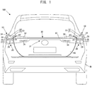
Fig. 1 is a rear view of an automobile in the embodiment according to the present invention. -
Fig. 2 is a side view of a vehicle rear portion of the automobile in the embodiment according to the present invention. -
Fig. 3 is a plan view of the vehicle rear potion of the automobile in the embodiment according to the present invention. -
Fig. 4 is a perspective view of the vehicle rear portion of the automobile in the embodiment according to the present invention. -
Fig. 5 is a perspective view showing a rear combination lamp case in the embodiment according to the present invention. -
Fig. 6 is a rear view showing the rear combination lamp case in the embodiment according to the present invention. -
Fig. 7 is a side view showing the rear combination lamp case in the embodiment according to the present invention. -
Fig. 8 is a plan view showing the rear combination lamp case in the embodiment according to the present invention. -
Fig. 9A is an end view showing the rear combination lamp case in the embodiment according to the present invention, the rear combination lamp case being sectioned along A-A cutting line inFig. 8 . -
Fig. 9B is an end view showing the rear combination lamp case in the embodiment according to the present invention, the rear combination lamp case being sectioned along B-B cutting line inFig. 8 . -
Fig. 9C is an end view showing the rear combination lamp case in the embodiment according to the present invention, the rear combination lamp case being sectioned along C-C cutting line inFig. 8 . -
Fig. 9D is an end view showing the rear combination lamp case in the embodiment according to the present invention, the rear combination lamp case being sectioned along D-D cutting line inFig. 8 . -
Fig. 9E is an end view showing the rear combination lamp case in the embodiment according to the present invention, the rear combination lamp case being sectioned along E-E cutting line inFig. 6 . -
Fig. 9F is an end view showing the rear combination lamp case in the embodiment according to the present invention, the rear combination lamp case being sectioned along F-F cutting line inFig. 6 . -
Fig. 10 is a perspective view showing fluid flow in a rear end portion of a left side face in the embodiment according to the present invention. -
Fig. 11 is a plan view showing the fluid flow in the rear end portion of the left side face in the embodiment according to the present invention. - The gist of the present invention lies in that a rear combination lamp case in a corner of a body rear portion is formed in a corner case having a substantial triangle pyramid shape by enclosing a rear plate, a side plate and a planner plate, wherein the rear plate forms a rear case face on which a concave notch portion is formed in a substantial center thereof, the side plate forms an air communication side face shaped so as to gradually become narrower width toward a rear thereof, the planner plate forms a concave air communication path a terminal end of which communicates with the concave notch portion of the rear plate in a center thereof, and the concave air communication path formed in the planner plate is formed so as to gradually become wider width from a body front over a body rear.
- The embodiment of the present invention will be described in detail with reference to
Figs. 1 to 11 . - In a rear portion of a
vehicle 100 of the present embodiment, as shown inFigs. 1 and4 , there are provided rearcombination lamp cases non-lighting area 30 arranged between the rearcombination lamp cases back door 60 positioned in front of thenon-lighting area 30. - Each of the rear
combination lamp cases rear plate 20 positioned at a rear portion of thevehicle 100, aside plate 40 formed at a side face of thevehicle 100 continuously to therear plate 20 and aplanner plate 50 continuing to an upper end portion of therear plate 20 and an upper end portion of theside plate 40. The rearcombination lamp case 10 is constituted in a substantial triangular pyramid shape by combining three plates. - As shown in
Figs. 1 and6 , therear plate 20 has a substantial rectangular shape in rear view and in therear plate 20, anotch portion 21 is formed to a side end portion 20' formed in an inner side along left and right direction of thevehicle 100 from a substantial center portion along left and right direction of the upper end portion. Further, it is formed aprotrusion 22 inclined in a climbing direction to a side face portion side of thevehicle 100 from a substantial center portion in left and right direction of the upper end portion of therear plate 20. Thisnotch portion 21 and theprotrusion 22 are smoothly connected with each other, thereby constitutes aconcave notch portion 23. - Inside the
rear plate 20, that is, in the rearcombination lamp case 10, there are arranged in a vehicle body B from an upper potion to a lower portion areflection plate 24, acomposite lamp 25, astop lamp 26 and aturn lamp 27. - The
reflection plate 24 is constituted in a substantial L-shape along theconcave notch portion 23 of therear plate 20. Further, thereflection plate 24 reflects light when light is illuminated from vehicle rear and can inform vehicle width of thevehicle 100 to a backward vehicle even if lamps of thevehicle 100 mentioned later are not turned on when parked/stopped. Based on that end portion of thereflection plate 24 at the side face portion side of thevehicle 100 is formed in a shape pushed up, positions of left and right end portions of thevehicle 100 can be easily recognized. - The
composite lamp 25 positions at a lower portion of thereflection plate 24 and is a lamp functioning in conjunction with thestop lamp 26 and theturn lamp 27 mentioned later. Thecomposite lamp 25 is formed in a substantial circle shape in rear view. - The
stop lamp 26 is formed in a substantial rectangular shape in rear view and is constituted from fourlight emitting portions 28, condenser lens (not shown) arranged to each rear portion of thelight emitting portion 28 to condense light illuminated from thelight emitting portion 28 and a reflection plate (not shown) arranged between thelight emitting portions 28 to reflect light being incident from therear plate 20. - Here, although the number of the
light emitting portion 28 in thestop lamp 26 is set to four in the present embodiment, such number of thelight emitting portion 28 is not limited to this. - The
turn lamp 27 is formed in a substantial rectangular shape in rear view and has alight emitting portion 29 arranged at a substantial center portion. To a rear portion of thelight emitting portion 29, it is arranged a condenser lens (not shown) to condense light illuminated from thelight emitting portion 29. Further, theturn lamp 27 is constituted in a stepwise fashion in planner view so as to gradually become wider width toward the rear direction of thevehicle 100. Reflection plate (not shown) are arranged on faces in a stepwise fashion. - As shown in
Figs. 2 ,7 ,9A and9D , theside plate 40 is formed in a substantial triangle shape in side view. Theside plate 40 constitutes anobtuse junction 46 by connecting tworidgeline portions Fig. 9D ) formed at a side end portion in the vehicle width direction of therear plate 20 and a ridgeline portion 56 (seeFig. 9A ) in the protrusive ridge portion 51 (seeFig. 9A ) of theplanner plate 50 with the substantial same shape in rear view as theprotrusion 22 of therear plate 20 extended to the front of thevehicle 100. - At an opposite side of the
junction 46, it is formed aninclined portion 43 which is gradually inclined downward in a rear direction of thevehicle 100 from afront end portion 52 of theplanner plate 50. Theinclined portion 43, as shown inFig. 7 , has a constitution that theinclined portion 43 rapidly descends while setting abent portion 44 formed in an obtuse angle as an inflection point. - In an outer side face 49 of the
side plate 40, as shown inFig. 9D , anair communication path 41 having a constant width is formed over a reference 48 (seeFigs. 7 and9C ) provided on theinclined portion 43 between thefront end portion 52 and thebent portion 44 from aridgeline center portion 47 formed at the substantial center portion in up and down direction of the sideend ridgeline portion 45. Thisair communication path 41, as shown in the end view ofFig. 9D , is substantially formed in a concave shape. Thus, theair communication path 41 functions so as to control air flow passing from a front to a rear when driving thevehicle 100. - On an inner side of the
side plate 40, that is, near the upper end of thevehicle 100 side face within the rearcombination lamp case 10, areflection plate 42 is installed in the vehicle body B. Thereflection plate 42 is constituted in a substantial similar shape to each side (substantial triangle portion enclosed by the sideend ridgeline portion 45 and the ridgeline portion 56) forming the substantial triangle portion in side view of theside plate 40. - The
planner plate 50, as shown inFigs. 3 and8 , has a substantial triangle shape in planner view and is constituted from the protrusive ridge portion 51 (seeFigs. 9D and 9F ) formed by extending theprotrusion 22 of therear plate 20 with the substantial same shape in rear view toward the front side of thevehicle 100, thefront end portion 52 to separate air passing toward a rear from a front of thevehicle 100 into left and right side faces of theprotrusive ridge portion 51 and a concaveair communication path 54 to pass air flowing in from thefront end portion 52 toward the rear of thevehicle 100. - The
protrusive ridge portion 51 is constituted so as to gradually become wider width in the inner direction of thevehicle 100 in planner view toward the rear of thevehicle 100 from thefront end portion 52. Arear end portion 53 of theprotrusive ridge portion 51 is smoothly connected with theprotrusion 22 by forming in the substantial same shape to theprotrusion 22 in rear view. Thus, theprotrusive ridge portion 51 is constituted so as not to inhibit air flow when driving thevehicle 100. - The
front end portion 52, as shown inFigs. 7, 8 and9A , is formed in a round shape so as to become an arc shape in side view, in planner view and in sectional end view. Therefore, thefront end portion 52 can separate fluid F communicating from the front when driving thevehicle 100 into left and right side face portions of theprotrusive ridge portion 51. That is, as shown inFig. 9A , the fluid F is separated into the outer side face 49 of theside plate 40 and the upper face of the concaveair communication path 54, thereafter passes toward the rear of thevehicle 100. - This concave
air communication path 54, as shown inFigs. 8 and9D , is constituted from aplanner portion 54a, a R-shapedface portion 54b with a substantial arc shape in sectional view and aconcave face portion 54c with a substantial concave shape. - As shown in
Fig. 8 , theplanner portion 54a is formed so as to gradually become wider width toward the inner side of thevehicle 100 as going to the rear of thevehicle 100 from thefront end portion 52. - Concretely, the
planner portion 54a, as shown inFig. 9A , is formed so as to become a plane with a narrower width near thefront end portion 52. Next, at the place shifted to the rear side of thevehicle 100 than the cutting line A, as shown inFig. 9B , theplanner portion 54a is formed so as to extend toward inner side in left and right direction of thevehicle 100. Next, at the place shifted to the rear side of thevehicle 100 than the cutting line B, as shown inFig. 9C , theplanner portion 54a is further formed so as to extend toward the inner side in left and right direction of thevehicle 100. Next, as shown inFig. 9D , theplanner portion 54a near therear end portion 55 has a width as same as the width of theplanner portion 54a at a point ofFig. 9C and theplanner portion 54a is formed so as to shift to the inner side in left and right direction of thevehicle 100 according to that theconcave face portion 54c mentioned later is formed. - As mentioned above, the
planner portion 54a is formed so as to gradually enlarge toward inner side in left and right direction of thevehicle 100 from thefront end portion 52 to therear end portion 55. Thereby, it concludes that theplanner portion 54a is formed so that flow path area of the fluid F when driving thevehicle 100 is gradually enlarged. - Further, the R-shaped
face portion 54b, as shown inFig. 9A , is arranged between theprotrusive ridge portion 51 and theplanner portion 54a and a cutting end face shape of the R-shapedface portion 54b is formed in a substantial arc shape. This R-shapedface portion 54b, as shown inFigs. 9A, 9B, 9C and9D , is always formed with a constant curvature radius from thefront end portion 52 to therear end portion 55. Therefore, the flow path area of the fluid F passing toward the rear while contacting with theprotrusive ridge portion 51 when driving thevehicle 100 becomes constant, thereby a pressure toward left and right direction occurring in theprotrusive ridge portion 51 can be always made constant. - The
concave face portion 54c, as shown inFig. 8 , positions near therear end portion 55 and, as shown inFig. 9D , theconcave face portion 54c is a hollow formed between theplanner portion 54a and the R-shapedface portion 54b. Therear end portion 55 and thenotch portion 21, as shown inFig. 9E , are smoothly continues. - The concave
air communication path 54, as shown inFig. 9E , is gradually inclined downward from thefront end portion 52 to therear end portion 55. The inclination angle increases in the hollow of theconcave face portion 54c near therear end portion 55, thereby the flow path area against up and down direction of the fluid F passing the upper face of the concaveair communication path 54 is enlarged. Therefore, downforce occurs at therear end portion 55 of the concaveair communication path 54, thereby it is reduced possibility that rear wheels of thevehicle 100 rises up from the road surface. - Further, as shown in
Fig. 1 , thenon-lighting area 30 is arranged between the rearcombination lamp cases vehicle 100. - The
non-lighting area 30 is formed in a substantial rectangular shape in rear view and has anotch portion 31 with a horizontal long shape at the substantial center lower portion. Further, it is formed aninclination portion 32 inclined downward toward the rear from the front of thevehicle 100 at the left and right upper end portions of thenon-lighting area 30. - Further, on inner side of the
non-lighting area 30, that is, near the upper end portion in the rear side of thevehicle 100, it is provided areflection plate 33 with a rectangular shape in rear view from one end portion of thenon-lighting area 30 to the other end thereof in left and right direction. Thisreflection plate 33 is arranged continuously to thereflection plate 24 formed on therear plate 20 mentioned above, thereby it can be given an impression as if thenon-lighting area 30 and the rearcombination lamp cases - Further,
fog lamps 34 are provided near left and right end portions of thenotch portion 31. Thefog lamp 34 has a substantial rectangular shape in rear view and is arranged under lower portion of thereflection plate 33. As shown inFig. 3 , thefog lamps 34 are arranged on steps (not shown) in stepwise shape in planner view formed along an arcuate shape in planner view at the rear end portion of the vehicle body B. Further, condenser lens (not shown) is arranged behind thefog lamps 34, thereby it is adopted constitution that visibility for a backward vehicle is improved when lighting and brightness equal to the conventional lamps can be realized in a case of low output. - Further, a baggage room at the vehicle rear is arranged in front of the
non-lighting area 30 and, to this baggage room, the openable and closableback door 60 is formed, as shown inFigs. 1 ,2 ,3 and4 . - Based on that the rear portion of the
vehicle 100 is constituted in the above, passing flow path of the fluid F (air) passing from the vehicle front can be controlled. Control contents of this passing flow path will be described in detail with reference toFigs. 10 and11 . In addition, it will be described below the reason why degree of freedom in design of the rearcombination lamp case 10 is improved. - The
vehicle 100 collides with the fluid F having a predetermined flow speed corresponding to driving speed thereof toward the rear from the front when driving. This fluid F contacts with thefront end portion 52 of eachprotrusive ridge portion 51 formed in each of the rearcombination lamp cases vehicle 100, thereby the fluid F is separated in left and right side faces of eachprotrusive ridge portion 51, that is , in the outer side face 49 of theside plate 40 and the upper face of the concaveair communication path 54 on theplanner plate 50, thereafter the fluid F flows to the rear of thevehicle 100. - Flow path area of the fluid F in left and right direction is reduced by the
protrusive ridge portion 51 and the fluid F becomes a dense state on the outer side face 49 of theside plate 40 and the upper face of the concaveair communication path 54, thereby flow speed thereof increases. As a result, the fluid F becomes a dense state on the outer side face 49 of theside plate 40 and the upper face of the concaveair communication path 54 and flow speed thereof increases. As a result, negative pressure occurs in the flow speed increase portion of the outer side face 49 of theside plate 40 and the concaveair communication path 54. Here, since the negative pressure equal to the left and right occurs on both the left and right faces of theprotrusive ridge portion 51, that is, on the inner side face (concave air communication path 54) and the outer side face (outer side face 49), theprotrusive ridge portion 51 is pulled by force equal to the left and right when driving thevehicle 100 and both forces counteract. Therefore, it will be reduced possibility that running of thevehicle 100 is hindered due to that thevehicle 100 is pulled in either of left and right directions. - Further, in a case that the
vehicle 100 shifts the body to the left direction as lane change when straightly running, the flow path area is reduced on the left side face of theprotrusive ridge portion 51 against running direction than on the right side face, thereby negative pressure state occurs. As a result, the rear portion of thevehicle 100 is pulled in the left side based on pressure difference occurring on the inner side face (concave air communication path 54) of theprotrusive ridge portion 51 and the outer side face (outer side face 49). Therefore, handle operation in lane change is promoted and lane change can be easily conducted. - Further, a driver feels that pressure change corresponding to the starting point in lane change existing to the most left direction occurs when the driver conducts lane change to the left side in the running direction and thereafter feels that displacement amount gradually decreases according to proceeding of lane change. Therefore, although pressure difference of the
vehicle 100 to the left direction occurs at the end of lane change and thevehicle 100 is also pulled to the left side, the driver remembers the pulling force at the start as a feeling. Since the pulling force difference to the left direction at the start and the end is large, the driver is hard to feel that pulling occurs by the negative pressure to the left side at the end of lane change, thereby it can be given an impression of easy operation. - Therefore, steering stability in driving of the vehicle can be secured in any case of straight driving and moving in left and right direction such as lane change.
- It will be described below lift and negative lift of the
vehicle 100 when driving the vehicle occurring by theconcave notch portion 23 formed in therear plate 20 and the concaveair communication path 54 formed in theplanner plate 50. - The concave
air communication path 54 formed on the upper face of theplanner plate 50 is gradually inclined downward from thefront end portion 52 to therear end portion 55 of the rear combination lamp case 10 (seeFig. 9E ) and the flow path area through which the fluid F passes increases and the flow speed of the fluid F decreases according to that the fluid F flown in thefront end portion 52 of the concaveair communication path 54 proceeds to therear end portion 55 of the concaveair communication path 54. As a result, the upper face of the concaveair communication path 54 becomes positive pressure and negative lift gradually rises up according to that the fluid F proceeds from thefront end portion 52 of the concaveair communication path 54 to therear end portion 55. That is, it concludes that the rear portion of thevehicle 100 is pressed down to the road surface by the fluid F, thereby there is an effect that steering stability can be improved by improving grip force of tires at driving. - Further, the
rear end portion 55 of the concaveair communication path 54 is constituted so as to be gradually inclined downward from thefront end portion 52 to therear end portion 55, thereby frictional resistance between the rearcombination lamp case 10 and the fluid F is reduced. As a result, the separation point where the fluid F separates from the rearcombination lamp case 10 can be shifted in the rear, thereby negative pressure area occurring in the rear of thevehicle 100 can be decreased and resistance force can be reduced. - Further, as shown in
Fig. 10 , in the present invention, steering stability of thevehicle 100 can be secured in a case that theprotrusive ridge portion 51, the concaveair communication path 54 and theprotrusion 22 are formed in the rearcombination lamp case 10, therefore the shape of resin parts (side plate 40 in the present invention) formed at the rear side face portions of thevehicle 100 can be voluntarily selected. Thus, resin area on which theside plate 40 of the rearcombination lamp case 10 is formed can be decreased and the side face portion of thevehicle 100 can be changed to metal having high processing accuracy. Accordingly, degree of freedom in design of the rearcombination lamp case 10 can be improved and strength of the side face portion of thevehicle 100 can be improved by the present invention. - Here, the present invention is not limited to the embodiment mentioned above and it is included in the scope of the present invention the constitution in which each constitution disclosed in the above embodiment is mutually substituted or combination thereof is changed or the constitution in which each constitution disclosed in well-known invention or the above embodiment is mutually substituted or combination thereof is changed. Further, the scope of the present invention is not limited to the above embodiment and is extended to matters described in claims of utility model application and equivalents thereof.
- Disclosed is a case structure for a rear combination lamp in an automobile in which a rear combination lamp case in a corner portion formed in a rear portion of a vehicle is formed in a corner case having a substantial triangle pyramid shape by a rear plate, a side plate and a planner plate,
wherein the rear plate forms a case rear face on which a concave notch portion is formed in a substantial center,
wherein the side plate forms an air communication side face which is formed so as to gradually become narrower width toward a rear thereof, and
wherein the planner plate forms a concave air communication path in a center thereof so that a terminal end of the concave air communication path communicates with the concave notch portion of the rear plate.
Claims (2)
- A case structure for a rear combination lamp in an automobile in which a rear combination lamp case in a corner portion formed in a rear portion of a vehicle is formed in a corner case having a substantial triangle pyramid shape by a rear plate, a side plate and a planner plate,
wherein the rear plate forms a case rear face on which a concave notch portion is formed in a substantial center,
wherein the side plate forms an air communication side face which is formed so as to gradually become narrower width toward a rear thereof, and
wherein the planner plate forms a concave air communication path in a center thereof so that a terminal end of the concave air communication path communicates with the concave notch portion of the rear plate. - The case structure according to claim 1,
wherein the concave air communication path formed in the planner plate is formed so as to gradually become wider width from a front to a rear thereof.
Applications Claiming Priority (1)
| Application Number | Priority Date | Filing Date | Title |
|---|---|---|---|
| JP2018033573A JP6951987B2 (en) | 2018-02-27 | 2018-02-27 | Rear combination lamp case structure for automobiles |
Publications (2)
| Publication Number | Publication Date |
|---|---|
| EP3552878A1 true EP3552878A1 (en) | 2019-10-16 |
| EP3552878B1 EP3552878B1 (en) | 2020-08-26 |
Family
ID=65576216
Family Applications (1)
| Application Number | Title | Priority Date | Filing Date |
|---|---|---|---|
| EP19159118.9A Not-in-force EP3552878B1 (en) | 2018-02-27 | 2019-02-25 | Case structure for rear combination lamp in automobile |
Country Status (4)
| Country | Link |
|---|---|
| US (1) | US10533725B2 (en) |
| EP (1) | EP3552878B1 (en) |
| JP (1) | JP6951987B2 (en) |
| CN (1) | CN110194217B (en) |
Families Citing this family (3)
| Publication number | Priority date | Publication date | Assignee | Title |
|---|---|---|---|---|
| JP7375660B2 (en) * | 2020-04-02 | 2023-11-08 | マツダ株式会社 | Vehicle rear body structure |
| CN111959612B (en) * | 2020-07-23 | 2021-10-26 | 浙江零跑科技股份有限公司 | Luggage-boot lid assembly of through type tail lamp |
| JP7174795B2 (en) * | 2021-03-10 | 2022-11-17 | 本田技研工業株式会社 | rear lamp control system |
Citations (3)
| Publication number | Priority date | Publication date | Assignee | Title |
|---|---|---|---|---|
| JP2004210138A (en) | 2002-12-27 | 2004-07-29 | Nissan Shatai Co Ltd | Rear fender panel |
| JP2015083459A (en) | 2010-05-07 | 2015-04-30 | トヨタ自動車株式会社 | Vehicle side structure |
| FR3021926A1 (en) * | 2014-06-10 | 2015-12-11 | Renault Sas | CLADDING MODULE FOR CUSTOMIZING A LIGHTING DEVICE FOR A MOTOR VEHICLE |
Family Cites Families (5)
| Publication number | Priority date | Publication date | Assignee | Title |
|---|---|---|---|---|
| JPH0628355Y2 (en) * | 1988-05-11 | 1994-08-03 | 三菱自動車工業株式会社 | Rear combination lamp bezel |
| JPH048681A (en) * | 1990-04-24 | 1992-01-13 | Honda Motor Co Ltd | Vehicle rear body structure |
| JP2008108470A (en) * | 2006-10-23 | 2008-05-08 | Ichikoh Ind Ltd | Vehicle lighting |
| JP5704403B2 (en) * | 2011-10-12 | 2015-04-22 | スズキ株式会社 | Car body rear structure |
| CN206623745U (en) * | 2017-03-31 | 2017-11-10 | 长城汽车股份有限公司 | taillight mounting assembly and vehicle body |
-
2018
- 2018-02-27 JP JP2018033573A patent/JP6951987B2/en not_active Expired - Fee Related
-
2019
- 2019-02-25 EP EP19159118.9A patent/EP3552878B1/en not_active Not-in-force
- 2019-02-26 CN CN201910141118.9A patent/CN110194217B/en not_active Expired - Fee Related
- 2019-02-27 US US16/287,095 patent/US10533725B2/en not_active Expired - Fee Related
Patent Citations (3)
| Publication number | Priority date | Publication date | Assignee | Title |
|---|---|---|---|---|
| JP2004210138A (en) | 2002-12-27 | 2004-07-29 | Nissan Shatai Co Ltd | Rear fender panel |
| JP2015083459A (en) | 2010-05-07 | 2015-04-30 | トヨタ自動車株式会社 | Vehicle side structure |
| FR3021926A1 (en) * | 2014-06-10 | 2015-12-11 | Renault Sas | CLADDING MODULE FOR CUSTOMIZING A LIGHTING DEVICE FOR A MOTOR VEHICLE |
Non-Patent Citations (1)
| Title |
|---|
| ANONYMOUS: "Lexus UX Rear Light Bar to Become "New Lexus Signature Feature" | Lexus Enthusiast", 22 March 2018 (2018-03-22), XP055606697, Retrieved from the Internet <URL:https://lexusenthusiast.com/2018/03/22/lexus-ux-rear-light-bar-to-become-new-lexus-signature-feature/> [retrieved on 20180322] * |
Also Published As
| Publication number | Publication date |
|---|---|
| JP2019147479A (en) | 2019-09-05 |
| US10533725B2 (en) | 2020-01-14 |
| JP6951987B2 (en) | 2021-10-20 |
| EP3552878B1 (en) | 2020-08-26 |
| CN110194217A (en) | 2019-09-03 |
| CN110194217B (en) | 2021-06-15 |
| US20190263459A1 (en) | 2019-08-29 |
Similar Documents
| Publication | Publication Date | Title |
|---|---|---|
| US10533725B2 (en) | Case structure for rear combination lamp in automobile | |
| EP2719607B1 (en) | Structure for rear portion of vehicle | |
| EP2757029A1 (en) | Saddle ride type vehicle | |
| EP1398256A2 (en) | Windscreen mounting structure for a motorcycle | |
| EP2195227A1 (en) | Vehicle and vehicle substructure | |
| EP2511162A1 (en) | Aerodynamic vehicle rear side body structure | |
| US20190092412A1 (en) | Saddle-type vehicle | |
| CN222202392U (en) | Variable spoiler lighting device for a vehicle | |
| EP2921351B1 (en) | Door mirror of vehicle | |
| EP2990310B1 (en) | Flow control device for vehicle | |
| JP2014054957A (en) | Vehicle front part structure | |
| WO2015001864A1 (en) | Door mirror device for vehicle | |
| JP6191550B2 (en) | Aerodynamic structure for vehicles | |
| JP5879056B2 (en) | Body structure | |
| EP1275315A2 (en) | Full-face type helmet for vehicular users | |
| CN218154140U (en) | Safety helmet LED indicating tail lamp | |
| CN217672860U (en) | Automobile front cover and automobile | |
| JP7155941B2 (en) | vehicle front structure | |
| JP4248758B2 (en) | Lamp device for vehicle | |
| US20250214659A1 (en) | Vehicle lower structure | |
| EP4303105B1 (en) | Bicycle handgrip device | |
| JP7790398B2 (en) | Door mirror structure | |
| EP4725809A1 (en) | Road vehicle with downforce wing provided with a deflector | |
| JP7735093B2 (en) | Side visor | |
| KR20250012409A (en) | Variable combination lamp and control method thereof |
Legal Events
| Date | Code | Title | Description |
|---|---|---|---|
| PUAI | Public reference made under article 153(3) epc to a published international application that has entered the european phase |
Free format text: ORIGINAL CODE: 0009012 |
|
| STAA | Information on the status of an ep patent application or granted ep patent |
Free format text: STATUS: REQUEST FOR EXAMINATION WAS MADE |
|
| 17P | Request for examination filed |
Effective date: 20190225 |
|
| AK | Designated contracting states |
Kind code of ref document: A1 Designated state(s): AL AT BE BG CH CY CZ DE DK EE ES FI FR GB GR HR HU IE IS IT LI LT LU LV MC MK MT NL NO PL PT RO RS SE SI SK SM TR |
|
| AX | Request for extension of the european patent |
Extension state: BA ME |
|
| GRAP | Despatch of communication of intention to grant a patent |
Free format text: ORIGINAL CODE: EPIDOSNIGR1 |
|
| STAA | Information on the status of an ep patent application or granted ep patent |
Free format text: STATUS: GRANT OF PATENT IS INTENDED |
|
| INTG | Intention to grant announced |
Effective date: 20200417 |
|
| GRAS | Grant fee paid |
Free format text: ORIGINAL CODE: EPIDOSNIGR3 |
|
| GRAA | (expected) grant |
Free format text: ORIGINAL CODE: 0009210 |
|
| STAA | Information on the status of an ep patent application or granted ep patent |
Free format text: STATUS: THE PATENT HAS BEEN GRANTED |
|
| AK | Designated contracting states |
Kind code of ref document: B1 Designated state(s): AL AT BE BG CH CY CZ DE DK EE ES FI FR GB GR HR HU IE IS IT LI LT LU LV MC MK MT NL NO PL PT RO RS SE SI SK SM TR |
|
| REG | Reference to a national code |
Ref country code: GB Ref legal event code: FG4D |
|
| REG | Reference to a national code |
Ref country code: CH Ref legal event code: EP |
|
| REG | Reference to a national code |
Ref country code: AT Ref legal event code: REF Ref document number: 1306073 Country of ref document: AT Kind code of ref document: T Effective date: 20200915 |
|
| REG | Reference to a national code |
Ref country code: IE Ref legal event code: FG4D |
|
| REG | Reference to a national code |
Ref country code: DE Ref legal event code: R096 Ref document number: 602019000528 Country of ref document: DE |
|
| REG | Reference to a national code |
Ref country code: LT Ref legal event code: MG4D |
|
| PG25 | Lapsed in a contracting state [announced via postgrant information from national office to epo] |
Ref country code: PT Free format text: LAPSE BECAUSE OF FAILURE TO SUBMIT A TRANSLATION OF THE DESCRIPTION OR TO PAY THE FEE WITHIN THE PRESCRIBED TIME-LIMIT Effective date: 20201228 Ref country code: NO Free format text: LAPSE BECAUSE OF FAILURE TO SUBMIT A TRANSLATION OF THE DESCRIPTION OR TO PAY THE FEE WITHIN THE PRESCRIBED TIME-LIMIT Effective date: 20201126 Ref country code: BG Free format text: LAPSE BECAUSE OF FAILURE TO SUBMIT A TRANSLATION OF THE DESCRIPTION OR TO PAY THE FEE WITHIN THE PRESCRIBED TIME-LIMIT Effective date: 20201126 Ref country code: LT Free format text: LAPSE BECAUSE OF FAILURE TO SUBMIT A TRANSLATION OF THE DESCRIPTION OR TO PAY THE FEE WITHIN THE PRESCRIBED TIME-LIMIT Effective date: 20200826 Ref country code: HR Free format text: LAPSE BECAUSE OF FAILURE TO SUBMIT A TRANSLATION OF THE DESCRIPTION OR TO PAY THE FEE WITHIN THE PRESCRIBED TIME-LIMIT Effective date: 20200826 Ref country code: SE Free format text: LAPSE BECAUSE OF FAILURE TO SUBMIT A TRANSLATION OF THE DESCRIPTION OR TO PAY THE FEE WITHIN THE PRESCRIBED TIME-LIMIT Effective date: 20200826 Ref country code: GR Free format text: LAPSE BECAUSE OF FAILURE TO SUBMIT A TRANSLATION OF THE DESCRIPTION OR TO PAY THE FEE WITHIN THE PRESCRIBED TIME-LIMIT Effective date: 20201127 Ref country code: FI Free format text: LAPSE BECAUSE OF FAILURE TO SUBMIT A TRANSLATION OF THE DESCRIPTION OR TO PAY THE FEE WITHIN THE PRESCRIBED TIME-LIMIT Effective date: 20200826 |
|
| REG | Reference to a national code |
Ref country code: NL Ref legal event code: MP Effective date: 20200826 |
|
| REG | Reference to a national code |
Ref country code: AT Ref legal event code: MK05 Ref document number: 1306073 Country of ref document: AT Kind code of ref document: T Effective date: 20200826 |
|
| PG25 | Lapsed in a contracting state [announced via postgrant information from national office to epo] |
Ref country code: RS Free format text: LAPSE BECAUSE OF FAILURE TO SUBMIT A TRANSLATION OF THE DESCRIPTION OR TO PAY THE FEE WITHIN THE PRESCRIBED TIME-LIMIT Effective date: 20200826 Ref country code: LV Free format text: LAPSE BECAUSE OF FAILURE TO SUBMIT A TRANSLATION OF THE DESCRIPTION OR TO PAY THE FEE WITHIN THE PRESCRIBED TIME-LIMIT Effective date: 20200826 Ref country code: NL Free format text: LAPSE BECAUSE OF FAILURE TO SUBMIT A TRANSLATION OF THE DESCRIPTION OR TO PAY THE FEE WITHIN THE PRESCRIBED TIME-LIMIT Effective date: 20200826 Ref country code: PL Free format text: LAPSE BECAUSE OF FAILURE TO SUBMIT A TRANSLATION OF THE DESCRIPTION OR TO PAY THE FEE WITHIN THE PRESCRIBED TIME-LIMIT Effective date: 20200826 Ref country code: IS Free format text: LAPSE BECAUSE OF FAILURE TO SUBMIT A TRANSLATION OF THE DESCRIPTION OR TO PAY THE FEE WITHIN THE PRESCRIBED TIME-LIMIT Effective date: 20201226 |
|
| PG25 | Lapsed in a contracting state [announced via postgrant information from national office to epo] |
Ref country code: EE Free format text: LAPSE BECAUSE OF FAILURE TO SUBMIT A TRANSLATION OF THE DESCRIPTION OR TO PAY THE FEE WITHIN THE PRESCRIBED TIME-LIMIT Effective date: 20200826 Ref country code: RO Free format text: LAPSE BECAUSE OF FAILURE TO SUBMIT A TRANSLATION OF THE DESCRIPTION OR TO PAY THE FEE WITHIN THE PRESCRIBED TIME-LIMIT Effective date: 20200826 Ref country code: DK Free format text: LAPSE BECAUSE OF FAILURE TO SUBMIT A TRANSLATION OF THE DESCRIPTION OR TO PAY THE FEE WITHIN THE PRESCRIBED TIME-LIMIT Effective date: 20200826 Ref country code: CZ Free format text: LAPSE BECAUSE OF FAILURE TO SUBMIT A TRANSLATION OF THE DESCRIPTION OR TO PAY THE FEE WITHIN THE PRESCRIBED TIME-LIMIT Effective date: 20200826 Ref country code: SM Free format text: LAPSE BECAUSE OF FAILURE TO SUBMIT A TRANSLATION OF THE DESCRIPTION OR TO PAY THE FEE WITHIN THE PRESCRIBED TIME-LIMIT Effective date: 20200826 |
|
| REG | Reference to a national code |
Ref country code: DE Ref legal event code: R097 Ref document number: 602019000528 Country of ref document: DE |
|
| PG25 | Lapsed in a contracting state [announced via postgrant information from national office to epo] |
Ref country code: AL Free format text: LAPSE BECAUSE OF FAILURE TO SUBMIT A TRANSLATION OF THE DESCRIPTION OR TO PAY THE FEE WITHIN THE PRESCRIBED TIME-LIMIT Effective date: 20200826 Ref country code: AT Free format text: LAPSE BECAUSE OF FAILURE TO SUBMIT A TRANSLATION OF THE DESCRIPTION OR TO PAY THE FEE WITHIN THE PRESCRIBED TIME-LIMIT Effective date: 20200826 Ref country code: ES Free format text: LAPSE BECAUSE OF FAILURE TO SUBMIT A TRANSLATION OF THE DESCRIPTION OR TO PAY THE FEE WITHIN THE PRESCRIBED TIME-LIMIT Effective date: 20200826 |
|
| PG25 | Lapsed in a contracting state [announced via postgrant information from national office to epo] |
Ref country code: SK Free format text: LAPSE BECAUSE OF FAILURE TO SUBMIT A TRANSLATION OF THE DESCRIPTION OR TO PAY THE FEE WITHIN THE PRESCRIBED TIME-LIMIT Effective date: 20200826 |
|
| PLBE | No opposition filed within time limit |
Free format text: ORIGINAL CODE: 0009261 |
|
| STAA | Information on the status of an ep patent application or granted ep patent |
Free format text: STATUS: NO OPPOSITION FILED WITHIN TIME LIMIT |
|
| PG25 | Lapsed in a contracting state [announced via postgrant information from national office to epo] |
Ref country code: IT Free format text: LAPSE BECAUSE OF FAILURE TO SUBMIT A TRANSLATION OF THE DESCRIPTION OR TO PAY THE FEE WITHIN THE PRESCRIBED TIME-LIMIT Effective date: 20200826 |
|
| 26N | No opposition filed |
Effective date: 20210527 |
|
| PG25 | Lapsed in a contracting state [announced via postgrant information from national office to epo] |
Ref country code: SI Free format text: LAPSE BECAUSE OF FAILURE TO SUBMIT A TRANSLATION OF THE DESCRIPTION OR TO PAY THE FEE WITHIN THE PRESCRIBED TIME-LIMIT Effective date: 20200826 |
|
| PG25 | Lapsed in a contracting state [announced via postgrant information from national office to epo] |
Ref country code: MC Free format text: LAPSE BECAUSE OF FAILURE TO SUBMIT A TRANSLATION OF THE DESCRIPTION OR TO PAY THE FEE WITHIN THE PRESCRIBED TIME-LIMIT Effective date: 20200826 |
|
| REG | Reference to a national code |
Ref country code: BE Ref legal event code: MM Effective date: 20210228 |
|
| PG25 | Lapsed in a contracting state [announced via postgrant information from national office to epo] |
Ref country code: LU Free format text: LAPSE BECAUSE OF NON-PAYMENT OF DUE FEES Effective date: 20210225 |
|
| PG25 | Lapsed in a contracting state [announced via postgrant information from national office to epo] |
Ref country code: IE Free format text: LAPSE BECAUSE OF NON-PAYMENT OF DUE FEES Effective date: 20210225 Ref country code: FR Free format text: LAPSE BECAUSE OF NON-PAYMENT OF DUE FEES Effective date: 20210228 |
|
| PGFP | Annual fee paid to national office [announced via postgrant information from national office to epo] |
Ref country code: DE Payment date: 20220224 Year of fee payment: 4 |
|
| PG25 | Lapsed in a contracting state [announced via postgrant information from national office to epo] |
Ref country code: BE Free format text: LAPSE BECAUSE OF NON-PAYMENT OF DUE FEES Effective date: 20210228 |
|
| REG | Reference to a national code |
Ref country code: CH Ref legal event code: PL |
|
| PG25 | Lapsed in a contracting state [announced via postgrant information from national office to epo] |
Ref country code: LI Free format text: LAPSE BECAUSE OF NON-PAYMENT OF DUE FEES Effective date: 20220228 Ref country code: CH Free format text: LAPSE BECAUSE OF NON-PAYMENT OF DUE FEES Effective date: 20220228 |
|
| PG25 | Lapsed in a contracting state [announced via postgrant information from national office to epo] |
Ref country code: CY Free format text: LAPSE BECAUSE OF FAILURE TO SUBMIT A TRANSLATION OF THE DESCRIPTION OR TO PAY THE FEE WITHIN THE PRESCRIBED TIME-LIMIT Effective date: 20200826 |
|
| PG25 | Lapsed in a contracting state [announced via postgrant information from national office to epo] |
Ref country code: HU Free format text: LAPSE BECAUSE OF FAILURE TO SUBMIT A TRANSLATION OF THE DESCRIPTION OR TO PAY THE FEE WITHIN THE PRESCRIBED TIME-LIMIT; INVALID AB INITIO Effective date: 20190225 |
|
| REG | Reference to a national code |
Ref country code: DE Ref legal event code: R119 Ref document number: 602019000528 Country of ref document: DE |
|
| GBPC | Gb: european patent ceased through non-payment of renewal fee |
Effective date: 20230225 |
|
| PG25 | Lapsed in a contracting state [announced via postgrant information from national office to epo] |
Ref country code: GB Free format text: LAPSE BECAUSE OF NON-PAYMENT OF DUE FEES Effective date: 20230225 |
|
| PG25 | Lapsed in a contracting state [announced via postgrant information from national office to epo] |
Ref country code: GB Free format text: LAPSE BECAUSE OF NON-PAYMENT OF DUE FEES Effective date: 20230225 Ref country code: DE Free format text: LAPSE BECAUSE OF NON-PAYMENT OF DUE FEES Effective date: 20230901 |
|
| PG25 | Lapsed in a contracting state [announced via postgrant information from national office to epo] |
Ref country code: MK Free format text: LAPSE BECAUSE OF FAILURE TO SUBMIT A TRANSLATION OF THE DESCRIPTION OR TO PAY THE FEE WITHIN THE PRESCRIBED TIME-LIMIT Effective date: 20200826 |
|
| PG25 | Lapsed in a contracting state [announced via postgrant information from national office to epo] |
Ref country code: TR Free format text: LAPSE BECAUSE OF FAILURE TO SUBMIT A TRANSLATION OF THE DESCRIPTION OR TO PAY THE FEE WITHIN THE PRESCRIBED TIME-LIMIT Effective date: 20200826 |
|
| PG25 | Lapsed in a contracting state [announced via postgrant information from national office to epo] |
Ref country code: MT Free format text: LAPSE BECAUSE OF FAILURE TO SUBMIT A TRANSLATION OF THE DESCRIPTION OR TO PAY THE FEE WITHIN THE PRESCRIBED TIME-LIMIT Effective date: 20200826 |