EP3552870A1 - Seat orientation adjustment device and safety seat - Google Patents
Seat orientation adjustment device and safety seat Download PDFInfo
- Publication number
- EP3552870A1 EP3552870A1 EP18881138.4A EP18881138A EP3552870A1 EP 3552870 A1 EP3552870 A1 EP 3552870A1 EP 18881138 A EP18881138 A EP 18881138A EP 3552870 A1 EP3552870 A1 EP 3552870A1
- Authority
- EP
- European Patent Office
- Prior art keywords
- seat
- locking
- adjustment device
- posture adjustment
- support rod
- Prior art date
- Legal status (The legal status is an assumption and is not a legal conclusion. Google has not performed a legal analysis and makes no representation as to the accuracy of the status listed.)
- Granted
Links
Images

Classifications
-
- B—PERFORMING OPERATIONS; TRANSPORTING
- B60—VEHICLES IN GENERAL
- B60N—SEATS SPECIALLY ADAPTED FOR VEHICLES; VEHICLE PASSENGER ACCOMMODATION NOT OTHERWISE PROVIDED FOR
- B60N2/00—Seats specially adapted for vehicles; Arrangement or mounting of seats in vehicles
- B60N2/24—Seats specially adapted for vehicles; Arrangement or mounting of seats in vehicles for particular purposes or particular vehicles
- B60N2/26—Seats specially adapted for vehicles; Arrangement or mounting of seats in vehicles for particular purposes or particular vehicles for children
- B60N2/28—Seats readily mountable on, and dismountable from, existing seats or other parts of the vehicle
- B60N2/2875—Seats readily mountable on, and dismountable from, existing seats or other parts of the vehicle inclinable, as a whole or partially
-
- A—HUMAN NECESSITIES
- A47—FURNITURE; DOMESTIC ARTICLES OR APPLIANCES; COFFEE MILLS; SPICE MILLS; SUCTION CLEANERS IN GENERAL
- A47D—FURNITURE SPECIALLY ADAPTED FOR CHILDREN
- A47D1/00—Children's chairs
- A47D1/002—Children's chairs adjustable
-
- B—PERFORMING OPERATIONS; TRANSPORTING
- B60—VEHICLES IN GENERAL
- B60N—SEATS SPECIALLY ADAPTED FOR VEHICLES; VEHICLE PASSENGER ACCOMMODATION NOT OTHERWISE PROVIDED FOR
- B60N2/00—Seats specially adapted for vehicles; Arrangement or mounting of seats in vehicles
- B60N2/24—Seats specially adapted for vehicles; Arrangement or mounting of seats in vehicles for particular purposes or particular vehicles
- B60N2/26—Seats specially adapted for vehicles; Arrangement or mounting of seats in vehicles for particular purposes or particular vehicles for children
- B60N2/28—Seats readily mountable on, and dismountable from, existing seats or other parts of the vehicle
-
- B—PERFORMING OPERATIONS; TRANSPORTING
- B60—VEHICLES IN GENERAL
- B60N—SEATS SPECIALLY ADAPTED FOR VEHICLES; VEHICLE PASSENGER ACCOMMODATION NOT OTHERWISE PROVIDED FOR
- B60N2/00—Seats specially adapted for vehicles; Arrangement or mounting of seats in vehicles
- B60N2/24—Seats specially adapted for vehicles; Arrangement or mounting of seats in vehicles for particular purposes or particular vehicles
- B60N2/26—Seats specially adapted for vehicles; Arrangement or mounting of seats in vehicles for particular purposes or particular vehicles for children
- B60N2/28—Seats readily mountable on, and dismountable from, existing seats or other parts of the vehicle
- B60N2/2821—Seats readily mountable on, and dismountable from, existing seats or other parts of the vehicle having a seat and a base part
-
- B—PERFORMING OPERATIONS; TRANSPORTING
- B60—VEHICLES IN GENERAL
- B60N—SEATS SPECIALLY ADAPTED FOR VEHICLES; VEHICLE PASSENGER ACCOMMODATION NOT OTHERWISE PROVIDED FOR
- B60N2/00—Seats specially adapted for vehicles; Arrangement or mounting of seats in vehicles
- B60N2/24—Seats specially adapted for vehicles; Arrangement or mounting of seats in vehicles for particular purposes or particular vehicles
- B60N2/26—Seats specially adapted for vehicles; Arrangement or mounting of seats in vehicles for particular purposes or particular vehicles for children
- B60N2/28—Seats readily mountable on, and dismountable from, existing seats or other parts of the vehicle
- B60N2/2869—Seats readily mountable on, and dismountable from, existing seats or other parts of the vehicle rotatable about a vertical axis
Definitions
- the present invention relates to the technical field of safety seats, in particular to a seat posture adjustment device and a safety seat.
- the posture (the tilt angle of the seat back) of a child safety seat is mostly adjustable.
- the posture of the child safety seat can be adjusted to a suitable angle at any time according to the child's age and safety.
- the child safety seat is generally provided with a seat posture adjustment device.
- the posture adjusting device includes a locking member divided into two sections which can move relative to each other, and when the locking member stretches out, the seat body and the seat support can be fixed relatively. When the locking member retracts, the locking between the seat body and the seat support is released, and the posture of the seat body can be adjusted; and after the adjustment is completed, the seat body and the seat support can be relocked by the reset of the locking member.
- the locking member usually needs to be placed in a special box together with a matched transmission mechanism, and then arranged between the seat body and the seat support, so that the posture adjusting device is relatively complicated in structure and occupies a large space which makes the overall volume of the seat body and the seat support be large.
- the two sections of the locking member retract from the seat body and the seat support, and the seat body and the seat support at the moment are disconnected.
- the seat body may deviate from the seat support, and the alignment of the seat body and the seat support cannot be ensured, which may cause the problem that the locking member cannot be reset successfully and cause unnecessary trouble.
- the objective of the present invention is to provide a seat posture adjustment device and a safety seat to improve the adjustment performance of the seat posture adjustment device as much as possible.
- the present invention provides a seat posture adjustment device including a locking member, a support rod arranged on a seat body and a guide groove formed in a seat support, wherein the support rod is inserted into the guide groove to connect the seat body and the seat support, the support rod is movable along the guide groove to realize the posture adjustment of the seat body, and the locking member is arranged on the support rod and movable relative to the support rod to realize locking or unlocking between the seat body and the seat support.
- the locking member is hollow and sleeved on the support rod, and is slidable relative to the support rod in the axial direction of the support rod.
- the seat posture adjustment device further includes a fitting structure, the fitting structure is fit with the locking member to realize relative locking of the seat body and the seat support when the locking member moves to a locking position, and disengages the fitting with the locking member to release the relative locking of the seat body and the seat support when the locking member departs from the locking position.
- the fitting structure includes a plurality of limit holes formed on the inner side of the seat support, the plurality of limit holes are arranged along the trajectory of the guide groove, and the locking member is inserted into a limit hole to realize the relative locking of the seat body and the seat support when the locking member moves to the locking position; and is disengaged from the limit hole to release the relative locking of the seat body and the seat support when the locking member departs from the locking position.
- the trajectory of the guide groove is an arc.
- the limit holes are counter bores.
- the seat posture adjustment device further includes a first elastic member for resetting the locking member.
- the seat posture adjustment device includes two locking members movable relative to the support rod, the first elastic member comprises a spring, the spring and the two locking members are sleeved on the support rod, and the spring is arranged between the two locking members.
- the seat posture adjustment device further includes an operation member, the operation member is configured to force the locking member to move relative to the support rod.
- the operation member includes a pull plate arranged on the seat body, the pull plate is provided with a chute arranged obliquely with respect to the axial direction of the support rod, the locking member is provided with a locking pillar which is inserted into the chute, and the locking pillar and the locking member are driven through the chute to move relative to the support rod when the pull plate is pulled.
- the seat posture adjustment device further includes a handle connected with the pull plate, and the handle is arranged on the bottom surface of the seat body and close to the front end of the seat body.
- the seat posture adjustment device further includes a second elastic member connected to the pull plate for resetting the pull plate.
- two second elastic members are arranged symmetrically about a center line of the pull plate.
- the seat posture adjustment device further includes a first limit structure for limiting the maximum movement distance of the pull plate.
- the first limit structure includes a first limit boss formed on the seat body and a limit slot formed in the pull plate, and the first limit boss is inserted into the limit slot to limit the maximum movement distance of the pull plate.
- the seat posture adjustment device further includes a second limit structure for limiting the movement path of the pull plate.
- the second limit structure includes a substantially L-shaped second limit boss on the seat body, the second limit boss extends in the front and rear direction of the seat body, the pull plate is located between the second limit boss and the bottom surface of the seat body, and the pull plate is supported by the second limit boss and movable in the extending direction of the second limit boss.
- the present invention further provides a safety seat including the above seat posture adjustment device.
- the seat support is provided with an open slot, the open slot communicates with the guide groove, and the support rod is assembled into the guide groove through the open slot.
- the locking member is arranged on the support rod, and moves relative to the support rod when the posture of the seat body is adjusted to realize locking or unlocking between the seat body and the seat support; in this way, the support rod plays a certain role in guiding the movement of the locking member, so that the reset of the locking member is smoother and more precise, and the reliability is improved.
- the support rod is arranged on the seat body and inserted into the guide groove formed in the seat support, and the support rod remains stationary and can always play a role in connecting the seat body and the seat support during the movement of the locking member, so during the posture adjustment of the seat body, the deviation between the seat body and the seat support can be avoided, and the alignment of the seat body and the seat support can be maintained, which can further ensure the smooth reset of the locking member and improve the adjustment performance of the seat posture adjustment device.
- the seat posture adjustment device includes a locking member 5, a support rod 3 arranged on a seat body 1 and a guide groove 4 formed in a seat support 2.
- the support rod 3 is inserted into the guide groove 4 to connect the seat body 1 and the seat support 2, and the support rod 3 can be moved in the guide groove 4 and guided via the guide groove 4 to realize the posture adjustment of the seat body 1.
- the locking member 5 is arranged on the support rod 3, and moves relative to the support rod 3 when the posture of the seat body 1 is adjusted to realize locking or unlocking between the seat body 1 and the seat support 2.
- the locking member 5 is arranged on the support rod 3, and moves relative to the support rod 3 when the posture of the seat body 1 is adjusted to realize locking or unlocking between the seat body 1 and the seat support 2, in this way, the support rod 3 plays a certain role in guiding the movement of the locking member 5, so that the reset of the locking member 5 is smoother and more precise, and the reliability is improved.
- the support rod 3 is arranged on the seat body 1 and inserted into the guide groove 4 formed in the seat support 2, and the support rod 3 remains stationary and can always play a role in connecting the seat body 1 and the seat support 2 during the movement of the locking member 5, so during the posture adjustment of the seat body 1, the deviation between the seat body 1 and the seat support 2 can be avoided, and the alignment of the seat body 1 and the seat support 2 can be maintained, which can further ensure the smooth reset of the locking member 5 and improve the adjustment performance of the seat posture adjustment device.
- the locking member 5 is of a hollow structure, is sleeved on the support rod 3, and can slide relative to the support rod 3 in the axial direction of the support rod 3.
- the locking member 5 is of a hollow structure and is sleeved on the support rod 3, so that the overall structure of the seat posture adjustment device can be more compact, and the occupied space is reduced.
- the support rod 3 can effectively guide the movement of the locking member 5, so that the movement of the locking member 5 is more precise.
- the seat posture adjustment device further includes a fitting structure for fitting with the locking member 5 to realize relative locking of the seat body 1 and the seat support 2 when the locking member 5 moves to a locking position capable of fitting with the fitting structure, and to release the relative locking of the seat body 1 and the seat support 2 when departing from the locking position.
- the specific structural form of the fitting structure may be various as long as it can fit with the locking member 5 to realize locking or unlocking between the seat body 1 and the seat support 2.
- the fitting structure includes a plurality of limit holes 10 formed on the inner side of the seat support 2, the plurality of limit holes 10 are arranged along the trajectory of the guide groove 4, and the locking member 5 can be inserted into a limit hole 10 when moving to the locking position to realize the relative locking of the seat body 1 and the seat support 2; and the locking member 5 is disengaged from the limit hole 10 when departing from the locking position to release the relative locking of the seat body 1 and the seat support 2.
- the seat body 1 can be fixed at different postures by using the limit holes 10 as a fitting structure.
- the limit holes 10 are counter bores, which can prevent the locking member 5 from penetrating through the outer side of the seat support 2, causing the problem that the locking member 5 interferes with other components or is easily lost or damaged, thereby improving the reliability.
- the trajectory of the guide groove 4 is an arc.
- the guide groove and the plurality of limit holes 10 are arranged along the arc to better fit the posture change of the seat body 1.
- the plurality of limit holes 10 are arranged along the trajectory of the guide groove 4, so that a plurality of locking positions of the locking member 5 can be kept in line with the moving direction of the support rod 3 to improve the overall coordination of the seat posture adjustment device.
- the plurality of limit holes 10 may be arranged at intervals, that is, the space occupied by each of the limit holes 10 does not overlap each other; the plurality of limit holes 10 may also be arranged in an overlapping manner, that is, a part of space may be shared by the two adjacent limit holes 10 to increase the number of the adjustable posture angles, so that the seat body 1 has more postures.
- the seat posture adjustment device further includes a first elastic member 6 for resetting the locking member 5.
- a first elastic member 6 for resetting the locking member 5.
- two locking members 5 are provided and can move relative to the support rod 3, the number of the first elastic member 6 is one and the first elastic member 6 includes a spring, the spring and the two locking members 5 are sleeved on the support rod 3, and the spring is arranged between the two locking members 5.
- One first elastic member 6 may be provided, one end of the first elastic member 6 is connected with one of the locking members 5, the other end is connected with the other locking member 5, and the positions of the first elastic member 6 and the two locking members 5 can be maintained under the action of a chute 12.
- two first elastic members 6 may also be provided, one end of each first elastic member 6 is connected with the support rod 3, and the other end is connected with the corresponding locking member 5.
- the seat posture adjustment device may further include an operation member for forcing the locking member 5 to move relative to the support rod 3.
- an operation member for forcing the locking member 5 to move relative to the support rod 3.
- the locking and unlocking of the seat body 1 can be realized through the movement of the locking member 5.
- the locking member 5 is locked in a normal state and unlocked when the posture of the seat body 1 needs to be adjusted.
- the specific structure of the operation member may be flexible as long as it can achieve its function.
- the operation member may include a pull plate 7 arranged on the seat body 1, the pull plate 7 is provided with a chute 12 arranged obliquely with respect to the axial direction of the support rod 3, the locking member 5 is provided with a locking pillar 8 which is inserted into the chute 12, and the locking pillar 8 and the locking member 5 are driven through the chute 12 to move relative to the support rod 3 when the pull plate 7 is pulled.
- the structure that movements of the locking pillar 8 and the locking member 5 are driven through the chute 12 is simple, compact and high in reliability, needs a few parts, occupies a small space, and can also effectively ensure the movement stability of the locking member 5.
- the pull plate 7 is connected with a handle, and the handle is arranged on the bottom surface of the seat body 1 and close to the front end of the seat body 1 such that the operator pulls the pull plate 7 through the handle at the front end of the seat body 1.
- the handle can bring convenience for the operator to pull the pull plate 7.
- the pull plate 7 is operated by pulling at the front end of the seat body 1, which is more in line with the manual operation habit, and is convenient for posture adjustment by one-hand operation.
- the seat posture adjustment device further includes a second elastic member 9 connected to the pull plate 7, and the second elastic member 9 is used for resetting the pull plate 7.
- the pull plate 7 can be smoothly reset without great effort of the operator.
- the bottom surface of the seat body 1 is provided with a connecting boss
- the second elastic member 9 may be a spring
- one end of the spring is connected with the pull plate 7
- the other end of the spring is connected with the connecting boss.
- two second elastic members 9 are provided and arranged symmetrically about the center line of the pull plate 7.
- the resetting ability can be enhanced, and the movement of the pull plate 7 is more stable and reliable.
- the seat posture adjustment device further includes a first limit structure for limiting the maximum movement distance of the pull plate 7.
- a first limit structure for limiting the maximum movement distance of the pull plate 7.
- the first limit structure includes a first limit boss 14 formed on the seat body 1 and a limit slot 13 formed in the pull plate 7, and the first limit boss 14 is inserted into the limit slot 13 to limit the maximum movement distance of the pull plate 7 through the length of the limit slot 13.
- the seat posture adjustment device further includes a second limit structure for limiting the movement path of the pull plate 7 and maintaining the stability of movement of the pull plate 7.
- a second limit structure for limiting the movement path of the pull plate 7 and maintaining the stability of movement of the pull plate 7.
- the second limit structure includes a substantially L-shaped second limit boss 15 formed on the seat body 1, the second limit boss 15 extends in the front and rear direction of the seat body 1, the pull plate 7 is located between the second limit boss 15 and the bottom surface of the seat body 1, and the pull plate 7 is supported by the second limit boss 15 and moved in the extending direction of the second limit boss 15.
- the present invention further provides a safety seat including the seat posture adjustment device.
- the safety seat further includes a seat support 2 provided with an open slot 11, and the open slot 11 communicates with the guide groove 4 to assemble the support rod 3 into the guide groove 4 through the open slot 11.
- the open slot 11 can facilitate the assembly of the support rod 3 and realize the detachable connection of the seat body 1 and the seat support 2.
- the seat posture adjustment device is arranged at a front end connection between the seat body 1 and the seat support 2, and the support rod can fit with the mounting groove at the rear end connection between the seat body 1 and the seat support 2 without resetting another seat posture adjustment device as long as the coordination of the front and rear adjustment is achieved.
- the seat body 1 is provided with the support rod 3, the seat support 2 is provided with the guide groove 4, and the support rod 3 is inserted into the guide groove 4.
- the support rod 3 is sleeved with two locking members 5 and a first elastic member 6, and each locking member 5 is provided with a locking pillar 8 extending in the radial direction of the locking member 5.
- the inner side surface of the seat body 1 is provided with three limit holes 10, and an open slot 11 communicating with the guide groove 4.
- the pull plate 7 and the second elastic member 9 are arranged on the bottom surface of the seat body 1, the pull plate 7 is provided with the chutes 12, the locking pillars 8 are inserted into the chutes 12, the pull plate 7 is further provided with the limit slot 13, the first limit boss 14 formed on the bottom surface of the seat body 1 is inserted into the limit slot 13, the bottom surface of the seat body 1 is further provided with the L-shaped second limit boss 15, the pull plate 7 is arranged on the second limit boss 15, and the pull plate 7 is supported, guided to move and limited by the second limit boss 15.
- the pull plate 7 is pulled forward by hand and slides forward in the limit direction of the second limit boss 15, the locking pillar 8 and the locking member 5 can be driven to move toward the middle under the action of the chute 12 during sliding, the locking member 5 is disengaged from the limit hole 10, the support rod 3 at the moment can slide freely in the guide groove 4 to realize the posture adjustment of the seat, the pull plate 7 is released when the locking member 5 moves to the next corresponding limit hole 10 and reset under the action of the second elastic member 9, the locking member 5 enters the limit hole 10 under the action of the first elastic member 6, and the support rod 3 at the moment cannot continue to slide, thereby achieving the purpose of locking the seat body 1.
- the first elastic member 6 is at a natural length
- the locking member 5 is inserted into the innermost limit hole 10, and the seat body 1 and the seat support 2 are locked.
- the pull plate 7 is pulled forward.
- the locking pillar 8 and the locking member 5 move inward relative to the support rod 3 under the drive of the chute 12, the first elastic member 6 is compressed, the locking member 5 is disengaged from the limit hole 10, the seat body 1 and the seat support 2 are unlocked, and the user can adjust the posture of the seat body 1 as needed.
- the seat body 1 is adjusted to align the locking member 5 with the outermost limit hole 10, and the posture of the seat body 1 has been changed.
- the pull plate 7 is released and reset under the action of the second elastic member 9.
- the locking member 5 moves outward relative to the support rod 3 till being inserted into the limit hole 10, the seat body 1 and the seat support 2 are relocked, and the posture adjustment process is completed.
- the seat posture adjustment device and the safety seat of the present invention have at least one or more of the following advantages:
Landscapes
- Engineering & Computer Science (AREA)
- Health & Medical Sciences (AREA)
- Child & Adolescent Psychology (AREA)
- General Health & Medical Sciences (AREA)
- Aviation & Aerospace Engineering (AREA)
- Transportation (AREA)
- Mechanical Engineering (AREA)
- Seats For Vehicles (AREA)
- Chairs For Special Purposes, Such As Reclining Chairs (AREA)
Abstract
Description
- This application claims the benefit of priority to China Patent Application No.
201711202455.1 filed on Nov. 27, 2017 - The present invention relates to the technical field of safety seats, in particular to a seat posture adjustment device and a safety seat.
- In order to better adapt to comfort and safety requirements of riding children, the posture (the tilt angle of the seat back) of a child safety seat is mostly adjustable. The posture of the child safety seat can be adjusted to a suitable angle at any time according to the child's age and safety.
- In order to realize the posture adjustment function, the child safety seat is generally provided with a seat posture adjustment device. In the relevant art, the posture adjusting device includes a locking member divided into two sections which can move relative to each other, and when the locking member stretches out, the seat body and the seat support can be fixed relatively. When the locking member retracts, the locking between the seat body and the seat support is released, and the posture of the seat body can be adjusted; and after the adjustment is completed, the seat body and the seat support can be relocked by the reset of the locking member.
- Although this structure can realize the adjustment of the seat posture, the locking member usually needs to be placed in a special box together with a matched transmission mechanism, and then arranged between the seat body and the seat support, so that the posture adjusting device is relatively complicated in structure and occupies a large space which makes the overall volume of the seat body and the seat support be large. In addition, when the posture of the seat body is adjusted, the two sections of the locking member retract from the seat body and the seat support, and the seat body and the seat support at the moment are disconnected. In the event of an accident during the adjustment, the seat body may deviate from the seat support, and the alignment of the seat body and the seat support cannot be ensured, which may cause the problem that the locking member cannot be reset successfully and cause unnecessary trouble.
- The objective of the present invention is to provide a seat posture adjustment device and a safety seat to improve the adjustment performance of the seat posture adjustment device as much as possible.
- To achieve the above objective, the present invention provides a seat posture adjustment device including a locking member, a support rod arranged on a seat body and a guide groove formed in a seat support, wherein the support rod is inserted into the guide groove to connect the seat body and the seat support, the support rod is movable along the guide groove to realize the posture adjustment of the seat body, and the locking member is arranged on the support rod and movable relative to the support rod to realize locking or unlocking between the seat body and the seat support.
- In some embodiments, the locking member is hollow and sleeved on the support rod, and is slidable relative to the support rod in the axial direction of the support rod.
- In some embodiments, the seat posture adjustment device further includes a fitting structure, the fitting structure is fit with the locking member to realize relative locking of the seat body and the seat support when the locking member moves to a locking position, and disengages the fitting with the locking member to release the relative locking of the seat body and the seat support when the locking member departs from the locking position.
- In some embodiments, the fitting structure includes a plurality of limit holes formed on the inner side of the seat support, the plurality of limit holes are arranged along the trajectory of the guide groove, and the locking member is inserted into a limit hole to realize the relative locking of the seat body and the seat support when the locking member moves to the locking position; and is disengaged from the limit hole to release the relative locking of the seat body and the seat support when the locking member departs from the locking position.
- In some embodiments, the trajectory of the guide groove is an arc.
- In some embodiments, the limit holes are counter bores.
- In some embodiments, the seat posture adjustment device further includes a first elastic member for resetting the locking member.
- In some embodiments, the seat posture adjustment device includes two locking members movable relative to the support rod, the first elastic member comprises a spring, the spring and the two locking members are sleeved on the support rod, and the spring is arranged between the two locking members.
- In some embodiments, the seat posture adjustment device further includes an operation member, the operation member is configured to force the locking member to move relative to the support rod.
- In some embodiments, the operation member includes a pull plate arranged on the seat body, the pull plate is provided with a chute arranged obliquely with respect to the axial direction of the support rod, the locking member is provided with a locking pillar which is inserted into the chute, and the locking pillar and the locking member are driven through the chute to move relative to the support rod when the pull plate is pulled.
- In some embodiments, the seat posture adjustment device further includes a handle connected with the pull plate, and the handle is arranged on the bottom surface of the seat body and close to the front end of the seat body.
- In some embodiments, the seat posture adjustment device further includes a second elastic member connected to the pull plate for resetting the pull plate.
- In some embodiments, two second elastic members are arranged symmetrically about a center line of the pull plate.
- In some embodiments, the seat posture adjustment device further includes a first limit structure for limiting the maximum movement distance of the pull plate.
- In some embodiments, the first limit structure includes a first limit boss formed on the seat body and a limit slot formed in the pull plate, and the first limit boss is inserted into the limit slot to limit the maximum movement distance of the pull plate.
- In some embodiments, the seat posture adjustment device further includes a second limit structure for limiting the movement path of the pull plate.
- In some embodiments, the second limit structure includes a substantially L-shaped second limit boss on the seat body, the second limit boss extends in the front and rear direction of the seat body, the pull plate is located between the second limit boss and the bottom surface of the seat body, and the pull plate is supported by the second limit boss and movable in the extending direction of the second limit boss.
- In order to achieve the above objective, the present invention further provides a safety seat including the above seat posture adjustment device.
- In some embodiments, the seat support is provided with an open slot, the open slot communicates with the guide groove, and the support rod is assembled into the guide groove through the open slot.
- Based on the above technical solution, the locking member is arranged on the support rod, and moves relative to the support rod when the posture of the seat body is adjusted to realize locking or unlocking between the seat body and the seat support; in this way, the support rod plays a certain role in guiding the movement of the locking member, so that the reset of the locking member is smoother and more precise, and the reliability is improved. Moreover, the support rod is arranged on the seat body and inserted into the guide groove formed in the seat support, and the support rod remains stationary and can always play a role in connecting the seat body and the seat support during the movement of the locking member, so during the posture adjustment of the seat body, the deviation between the seat body and the seat support can be avoided, and the alignment of the seat body and the seat support can be maintained, which can further ensure the smooth reset of the locking member and improve the adjustment performance of the seat posture adjustment device.
- The accompanying drawings described here are used for providing a further understanding on the present invention, and constitute a part of the present application. The schematic embodiments of the present invention and the descriptions thereof are used for interpreting the present invention, rather than constituting improper limitations to the present invention. In which:
-
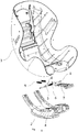
FIG. 1 is an exploded view of one embodiment of a safety seat according to the present invention. -
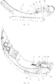
FIG. 2 is a structure diagram after a seat support in one embodiment of the safety seat according to the present invention is split from the middle. -
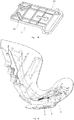
FIG. 3 is a structure diagram after a seat body in one embodiment of the safety seat according to the present invention is split from the middle. -
FIG. 4 is a structure diagram of a pull plate in one embodiment of a seat posture adjustment device according to the present invention. -
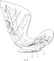
FIG. 5 is a structure diagram of one embodiment of the safety seat according to the present invention in a first state during posture adjustment. -
FIG. 6 is a structure diagram of one embodiment of the safety seat according to the present invention in a second state during posture adjustment. -
FIG. 7 is a structure diagram of one embodiment of the safety seat according to the present invention in a third state during posture adjustment. -
FIG. 8 is a structure diagram of one embodiment of the safety seat according to the present invention in a fourth state during posture adjustment. - In which:
1, seat body; 2, seat support; 3, support rod; 4, guide groove; 5, locking member; 6, first elastic member; 7, pull plate; 8, locking pillar; 10; limit hole; 11, open slot; 12, chute; 13, limit slot; 14, first limit boss; 15, second limit boss. - The following description will clearly and completely describe the technical solutions in the embodiments with reference to the accompanying drawings in the embodiments of the present invention. Apparently, the embodiments described are only part of the embodiments of the present invention, rather than all of them. All other embodiments obtained by those of ordinary skill in the art based on the embodiments of the present invention without any creative effort shall fall within the protection scope of the present invention.
- In the description of the present invention, it should be understood that the terms "center", "transverse", "longitudinal", "front", "back", "left", "right", "upper", "lower", "vertical", "horizontal", "top", "bottom", "inner", "outer" and the like indicate the orientations or positional relationships based on the orientation or position relationships shown in the drawings. The terms are only for the convenience of describing the present invention and simplification of the description, but do not indicate or imply that the referred devices or units must have specific orientations or be constructed and operated in specific orientations. Therefore, the terms should not be understood to limit the present invention.
- As shown in
FIG. 1 , in an exemplary embodiment of a seat posture adjustment device provided by the present invention, the seat posture adjustment device includes alocking member 5, asupport rod 3 arranged on aseat body 1 and aguide groove 4 formed in aseat support 2. Thesupport rod 3 is inserted into theguide groove 4 to connect theseat body 1 and theseat support 2, and thesupport rod 3 can be moved in theguide groove 4 and guided via theguide groove 4 to realize the posture adjustment of theseat body 1. Thelocking member 5 is arranged on thesupport rod 3, and moves relative to thesupport rod 3 when the posture of theseat body 1 is adjusted to realize locking or unlocking between theseat body 1 and theseat support 2. - In the above embodiment, the
locking member 5 is arranged on thesupport rod 3, and moves relative to thesupport rod 3 when the posture of theseat body 1 is adjusted to realize locking or unlocking between theseat body 1 and theseat support 2, in this way, thesupport rod 3 plays a certain role in guiding the movement of thelocking member 5, so that the reset of thelocking member 5 is smoother and more precise, and the reliability is improved. Moreover, thesupport rod 3 is arranged on theseat body 1 and inserted into theguide groove 4 formed in theseat support 2, and thesupport rod 3 remains stationary and can always play a role in connecting theseat body 1 and theseat support 2 during the movement of thelocking member 5, so during the posture adjustment of theseat body 1, the deviation between theseat body 1 and theseat support 2 can be avoided, and the alignment of theseat body 1 and theseat support 2 can be maintained, which can further ensure the smooth reset of thelocking member 5 and improve the adjustment performance of the seat posture adjustment device. - Further, the
locking member 5 is of a hollow structure, is sleeved on thesupport rod 3, and can slide relative to thesupport rod 3 in the axial direction of thesupport rod 3. Thelocking member 5 is of a hollow structure and is sleeved on thesupport rod 3, so that the overall structure of the seat posture adjustment device can be more compact, and the occupied space is reduced. In addition, thesupport rod 3 can effectively guide the movement of thelocking member 5, so that the movement of thelocking member 5 is more precise. - Optionally, the seat posture adjustment device further includes a fitting structure for fitting with the
locking member 5 to realize relative locking of theseat body 1 and theseat support 2 when thelocking member 5 moves to a locking position capable of fitting with the fitting structure, and to release the relative locking of theseat body 1 and theseat support 2 when departing from the locking position. - The specific structural form of the fitting structure may be various as long as it can fit with the locking
member 5 to realize locking or unlocking between theseat body 1 and theseat support 2. - In a preferred embodiment, as shown in
FIG. 2 , the fitting structure includes a plurality of limit holes 10 formed on the inner side of theseat support 2, the plurality of limit holes 10 are arranged along the trajectory of theguide groove 4, and the lockingmember 5 can be inserted into alimit hole 10 when moving to the locking position to realize the relative locking of theseat body 1 and theseat support 2; and the lockingmember 5 is disengaged from thelimit hole 10 when departing from the locking position to release the relative locking of theseat body 1 and theseat support 2. Theseat body 1 can be fixed at different postures by using the limit holes 10 as a fitting structure. - Optionally, the limit holes 10 are counter bores, which can prevent the locking
member 5 from penetrating through the outer side of theseat support 2, causing the problem that the lockingmember 5 interferes with other components or is easily lost or damaged, thereby improving the reliability. - Optionally, the trajectory of the
guide groove 4 is an arc. The guide groove and the plurality of limit holes 10 are arranged along the arc to better fit the posture change of theseat body 1. The plurality of limit holes 10 are arranged along the trajectory of theguide groove 4, so that a plurality of locking positions of the lockingmember 5 can be kept in line with the moving direction of thesupport rod 3 to improve the overall coordination of the seat posture adjustment device. - The plurality of limit holes 10 may be arranged at intervals, that is, the space occupied by each of the limit holes 10 does not overlap each other; the plurality of limit holes 10 may also be arranged in an overlapping manner, that is, a part of space may be shared by the two adjacent limit holes 10 to increase the number of the adjustable posture angles, so that the
seat body 1 has more postures. - Further, the seat posture adjustment device further includes a first
elastic member 6 for resetting the lockingmember 5. By providing the firstelastic member 6, the lockingmember 5 can be reset more smoothly and the operability can be improved. - Specifically, two locking
members 5 are provided and can move relative to thesupport rod 3, the number of the firstelastic member 6 is one and the firstelastic member 6 includes a spring, the spring and the two lockingmembers 5 are sleeved on thesupport rod 3, and the spring is arranged between the two lockingmembers 5. One firstelastic member 6 may be provided, one end of the firstelastic member 6 is connected with one of thelocking members 5, the other end is connected with the other lockingmember 5, and the positions of the firstelastic member 6 and the two lockingmembers 5 can be maintained under the action of achute 12. In other embodiments, two firstelastic members 6 may also be provided, one end of each firstelastic member 6 is connected with thesupport rod 3, and the other end is connected with the corresponding lockingmember 5. - Optionally, the seat posture adjustment device may further include an operation member for forcing the locking
member 5 to move relative to thesupport rod 3. By providing the operation member, the movement of the lockingmember 5 can be controlled. The locking and unlocking of theseat body 1 can be realized through the movement of the lockingmember 5. The lockingmember 5 is locked in a normal state and unlocked when the posture of theseat body 1 needs to be adjusted. - The specific structure of the operation member may be flexible as long as it can achieve its function.
- Specifically, as shown in
FIG. 3 andFIG. 4 , the operation member may include apull plate 7 arranged on theseat body 1, thepull plate 7 is provided with achute 12 arranged obliquely with respect to the axial direction of thesupport rod 3, the lockingmember 5 is provided with a lockingpillar 8 which is inserted into thechute 12, and the lockingpillar 8 and the lockingmember 5 are driven through thechute 12 to move relative to thesupport rod 3 when thepull plate 7 is pulled. The structure that movements of the lockingpillar 8 and the lockingmember 5 are driven through thechute 12 is simple, compact and high in reliability, needs a few parts, occupies a small space, and can also effectively ensure the movement stability of the lockingmember 5. - Further, the
pull plate 7 is connected with a handle, and the handle is arranged on the bottom surface of theseat body 1 and close to the front end of theseat body 1 such that the operator pulls thepull plate 7 through the handle at the front end of theseat body 1. The handle can bring convenience for the operator to pull thepull plate 7. Thepull plate 7 is operated by pulling at the front end of theseat body 1, which is more in line with the manual operation habit, and is convenient for posture adjustment by one-hand operation. - Optionally, the seat posture adjustment device further includes a second
elastic member 9 connected to thepull plate 7, and the secondelastic member 9 is used for resetting thepull plate 7. By providing the secondelastic member 9, thepull plate 7 can be smoothly reset without great effort of the operator. - Specifically, the bottom surface of the
seat body 1 is provided with a connecting boss, the secondelastic member 9 may be a spring, one end of the spring is connected with thepull plate 7, and the other end of the spring is connected with the connecting boss. When the spring is at a natural length, thepull plate 7 is located on the lower inner side of theseat body 1. After thepull plate 7 is pulled out, the spring is stretched. After the posture adjustment is completed, thepull plate 7 is released and can be reset under the action of the spring. - Optionally, two second
elastic members 9 are provided and arranged symmetrically about the center line of thepull plate 7. Thus, the resetting ability can be enhanced, and the movement of thepull plate 7 is more stable and reliable. - Optionally, the seat posture adjustment device further includes a first limit structure for limiting the maximum movement distance of the
pull plate 7. By providing the first limit structure, thepull plate 7 can be prevented from moving excessively to break thelocking pillar 8 so as to protect thelocking pillar 8. - Specifically, as shown in
FIG. 4 , the first limit structure includes afirst limit boss 14 formed on theseat body 1 and alimit slot 13 formed in thepull plate 7, and thefirst limit boss 14 is inserted into thelimit slot 13 to limit the maximum movement distance of thepull plate 7 through the length of thelimit slot 13. - Optionally, the seat posture adjustment device further includes a second limit structure for limiting the movement path of the
pull plate 7 and maintaining the stability of movement of thepull plate 7. By providing the second limit structure, the movement of thepull plate 7 can be guided to ensure that thepull plate 7 moves according to the preset route and is prevented from movement deviation to cause the unlocking failure of the lockingmember 5. - Specifically, the second limit structure includes a substantially L-shaped
second limit boss 15 formed on theseat body 1, thesecond limit boss 15 extends in the front and rear direction of theseat body 1, thepull plate 7 is located between thesecond limit boss 15 and the bottom surface of theseat body 1, and thepull plate 7 is supported by thesecond limit boss 15 and moved in the extending direction of thesecond limit boss 15. - Based on the seat posture adjustment device in each of the above embodiments, the present invention further provides a safety seat including the seat posture adjustment device.
- Optionally, the safety seat further includes a
seat support 2 provided with anopen slot 11, and theopen slot 11 communicates with theguide groove 4 to assemble thesupport rod 3 into theguide groove 4 through theopen slot 11. Theopen slot 11 can facilitate the assembly of thesupport rod 3 and realize the detachable connection of theseat body 1 and theseat support 2. - Optionally, the seat posture adjustment device is arranged at a front end connection between the
seat body 1 and theseat support 2, and the support rod can fit with the mounting groove at the rear end connection between theseat body 1 and theseat support 2 without resetting another seat posture adjustment device as long as the coordination of the front and rear adjustment is achieved. - The positive technical effects of the seat posture adjustment device in the above various embodiments are also applicable to the safety seat, and are not repeated herein.
- The operating process of one embodiment of the seat posture adjustment device and the safety seat according to the present invention will be described below with reference to
FIGS. 1-8 . - As shown in
FIGS. 1 to 4 , theseat body 1 is provided with thesupport rod 3, theseat support 2 is provided with theguide groove 4, and thesupport rod 3 is inserted into theguide groove 4. Thesupport rod 3 is sleeved with two lockingmembers 5 and a firstelastic member 6, and each lockingmember 5 is provided with a lockingpillar 8 extending in the radial direction of the lockingmember 5. The inner side surface of theseat body 1 is provided with threelimit holes 10, and anopen slot 11 communicating with theguide groove 4. Thepull plate 7 and the secondelastic member 9 are arranged on the bottom surface of theseat body 1, thepull plate 7 is provided with thechutes 12, the lockingpillars 8 are inserted into thechutes 12, thepull plate 7 is further provided with thelimit slot 13, thefirst limit boss 14 formed on the bottom surface of theseat body 1 is inserted into thelimit slot 13, the bottom surface of theseat body 1 is further provided with the L-shapedsecond limit boss 15, thepull plate 7 is arranged on thesecond limit boss 15, and thepull plate 7 is supported, guided to move and limited by thesecond limit boss 15. - Operation steps: the
pull plate 7 is pulled forward by hand and slides forward in the limit direction of thesecond limit boss 15, the lockingpillar 8 and the lockingmember 5 can be driven to move toward the middle under the action of thechute 12 during sliding, the lockingmember 5 is disengaged from thelimit hole 10, thesupport rod 3 at the moment can slide freely in theguide groove 4 to realize the posture adjustment of the seat, thepull plate 7 is released when the lockingmember 5 moves to the nextcorresponding limit hole 10 and reset under the action of the secondelastic member 9, the lockingmember 5 enters thelimit hole 10 under the action of the firstelastic member 6, and thesupport rod 3 at the moment cannot continue to slide, thereby achieving the purpose of locking theseat body 1. - Specifically, as shown in
FIG. 5 , in the normal state, the firstelastic member 6 is at a natural length, the lockingmember 5 is inserted into theinnermost limit hole 10, and theseat body 1 and theseat support 2 are locked. - As shown in
FIG. 6 , thepull plate 7 is pulled forward. During the sliding process of thepull plate 7, the lockingpillar 8 and the lockingmember 5 move inward relative to thesupport rod 3 under the drive of thechute 12, the firstelastic member 6 is compressed, the lockingmember 5 is disengaged from thelimit hole 10, theseat body 1 and theseat support 2 are unlocked, and the user can adjust the posture of theseat body 1 as needed. - As shown in
FIG. 7 , theseat body 1 is adjusted to align the lockingmember 5 with theoutermost limit hole 10, and the posture of theseat body 1 has been changed. - As shown in
FIG. 8 , thepull plate 7 is released and reset under the action of the secondelastic member 9. Under the action of thechute 12 and the firstelastic member 6, the lockingmember 5 moves outward relative to thesupport rod 3 till being inserted into thelimit hole 10, theseat body 1 and theseat support 2 are relocked, and the posture adjustment process is completed. - The terms "front", "rear", "inner" and "outer" mentioned in the description of the above process are based on the state after the seat is installed, but do not limit the structure and installation direction of the seat. Simple substitutions within the understandable scope of those skilled in the art shall be within the scope of the present invention.
- Through the description of various embodiments of the seat posture adjustment device and the safety seat of the present invention, it can be seen that the seat posture adjustment device and the safety seat of the present invention have at least one or more of the following advantages:
- 1. The locking member is arranged on the support rod, and the locking and unlocking between the seat body and the seat support are realized by the movement of the locking member relative to the support rod, so that in the unlocking state, the support rod can still play a role in connecting the seat body and the seat support, the alignment of the seat body and the seat support is ensured, the locking member can be smoothly reset, and the support rod itself has a certain guiding effect on the movement of the locking member;
- 2. The locking member is of a hollow structure and sleeved on the support rod, so that the overall structure is more compact and the occupied space is reduced;
- 3. The locking member is provided with a locking pillar, the pull plate is provided with a chute, and the locking pillar and the locking member can be driven to move through the chute when the pull plate is moved, so that the locking member is locked, the structure is simple, the movement is reliable, and the applicability is strong;
- 4. The seat body is provided with a limit structure for limiting the movement distance and movement path of the pull plate, thereby improving the accuracy and controllability of movement of the pull plate.
- Finally, it should be noted that the above embodiments are only for describing, instead of limiting, the technical solutions of the present invention. Although the present invention has been described in detail with reference to the preferred embodiments, those of ordinary skill in the art should understood that the specific embodiments of the present invention may still be modified, or part of the technical features may be equivalently substituted without departing from the spirit of the technical solutions of the present invention, and such modifications or substitutions shall fall within the scope of the technical solutions of the present invention.
Claims (19)
- A seat posture adjustment device, comprising a locking member (5), a support rod (3) arranged on a seat body (1) and a guide groove (4) formed in the seat support (2), wherein the support rod (3) is inserted into the guide groove (4) to connect the seat body (1) and the seat support (2), and the support rod (3) is movable along the guide groove (4) to realize the posture adjustment of the seat body (1), and the locking member (5) is arranged on the support rod (3) and movable relative to the support rod (3) to realize locking or unlocking between the seat body (1) and the seat support (2).
- The seat posture adjustment device according to claim 1, wherein the locking member (5) is hollow and sleeved on the support rod (3), and is slidable relative to the support rod (3) in the axial direction of the support rod (3).
- The seat posture adjustment device according to claim 1, further comprising a fitting structure, the fitting structure is fit with the locking member (5) to realize relative locking of the seat body (1) and the seat support (2) when the locking member (5) moves to a locking position, and disengages the fitting with the locking member (5) to release the relative locking of the seat body (1) and the seat support (2) when the locking member (5) departs from the locking position.
- The seat posture adjustment device according to claim 3, wherein the fitting structure comprises a plurality of limit holes (10) formed on the inner side of the seat support (2), the plurality of limit holes (10) are arranged along the trajectory of the guide groove (4), and the locking member (5) is inserted into a limit hole (10) to realize the relative locking of the seat body (1) and the seat support (2) when the locking member (5) moves to the locking position; and is disengaged from the limit hole (10) to release the relative locking of the seat body (1) and the seat support (2) when the locking member (5) departs from the locking position.
- The seat posture adjustment device according to claim 4, wherein the trajectory of the guide groove (4) is an arc.
- The seat posture adjustment device according to claim 4, wherein the limit holes (10) are counter bores.
- The seat posture adjustment device according to claim 1, further comprising a first elastic member (6) for resetting the locking member (5).
- The seat posture adjustment device according to claim 7, comprising two locking members (5) movable relative to the support rod (3), the first elastic member (6) comprises a spring, the spring and the two locking members (5) are sleeved on the support rod (3), and the spring is arranged between the two locking members (5).
- The seat posture adjustment device according to claim 1, further comprising an operation member, the operation member is configured to force the locking member (5) to move relative to the support rod (3).
- The seat posture adjustment device according to claim 9, wherein the operation member comprises a pull plate (7) arranged on the seat body (1), the pull plate (7) is provided with a chute (12) arranged obliquely with respect to the axial direction of the support rod (3), the locking member (5) is provided with a locking pillar (8) which is inserted into the chute (12), and the locking pillar (8) and the locking member (5) are driven through the chute (12) to move relative to the support rod (3) when the pull plate (7) is pulled.
- The seat posture adjustment device according to claim 10, further comprising a handle connected with the pull plate (7), and the handle is arranged on the bottom surface of the seat body (1) and close to the front end of the seat body (1).
- The seat posture adjustment device according to claim 10, further comprising a second elastic member (9) connected to the pull plate (7)for resetting the pull plate (7).
- The seat posture adjustment device according to claim 12, wherein two second elastic members (9) are arranged symmetrically about a center line of the pull plate (7).
- The seat posture adjustment device according to claim 10, further comprising a first limit structure for limiting the maximum movement distance of the pull plate (7).
- The seat posture adjustment device according to claim 14, wherein the first limit structure comprises a first limit boss (14) on the seat body (1) and a limit slot (13) in the pull plate (7), the first limit boss (14) is inserted into the limit slot (13) to limit the maximum movement distance of the pull plate (7).
- The seat posture adjustment device according to claim 10, further comprising a second limit structure for limiting the movement path of the pull plate (7).
- The seat posture adjustment device according to claim 16, wherein the second limit structure comprises a substantially L-shaped second limit boss (15) on the seat body (1), the second limit boss (15) extends in the front and rear direction of the seat body (1), the pull plate (7) is located between the second limit boss (15) and the bottom surface of the seat body (1), and the pull plate (7) is supported by the second limit boss (15) and movable in the extending direction of the second limit boss (15).
- A safety seat, comprising the seat posture adjustment device according to any one of claims 1-17.
- The safety seat according to claim 18, wherein the seat support (2) is provided with an open slot (11), the open slot (11) communicates with the guide groove (4), and the support rod (3) is assembled into the guide groove (4) through the open slot (11).
Applications Claiming Priority (2)
| Application Number | Priority Date | Filing Date | Title |
|---|---|---|---|
| CN201711202455.1A CN109835219B (en) | 2017-11-27 | 2017-11-27 | Seat posture adjustment device and safety seat |
| PCT/CN2018/072437 WO2019100567A1 (en) | 2017-11-27 | 2018-01-12 | Seat orientation adjustment device and safety seat |
Publications (3)
| Publication Number | Publication Date |
|---|---|
| EP3552870A1 true EP3552870A1 (en) | 2019-10-16 |
| EP3552870A4 EP3552870A4 (en) | 2020-07-22 |
| EP3552870B1 EP3552870B1 (en) | 2022-08-17 |
Family
ID=66631805
Family Applications (1)
| Application Number | Title | Priority Date | Filing Date |
|---|---|---|---|
| EP18881138.4A Active EP3552870B1 (en) | 2017-11-27 | 2018-01-12 | Seat orientation adjustment device and safety seat |
Country Status (4)
| Country | Link |
|---|---|
| US (1) | US11400838B2 (en) |
| EP (1) | EP3552870B1 (en) |
| CN (1) | CN109835219B (en) |
| WO (1) | WO2019100567A1 (en) |
Families Citing this family (6)
| Publication number | Priority date | Publication date | Assignee | Title |
|---|---|---|---|---|
| US11807141B2 (en) * | 2019-01-10 | 2023-11-07 | Clek Inc. | Child safety seat with energy absorber |
| CN112440840B (en) * | 2019-08-29 | 2025-02-11 | 珠海弘点科技有限公司 | Child safety seats |
| CN111184370B (en) * | 2020-02-26 | 2025-08-12 | 麦克英孚(宁波)婴童用品有限公司 | Chair back adjusting device and chair |
| CN111345611A (en) * | 2020-05-20 | 2020-06-30 | 成业兴 | Chair suitable for various body postures and table matched with chair |
| CN112498196B (en) * | 2020-11-30 | 2025-01-24 | 宁波宝贝第一母婴用品有限公司 | A safety seat |
| US12472853B2 (en) * | 2021-10-21 | 2025-11-18 | Dorel Juvenile Group, Inc. | Child restraint |
Family Cites Families (12)
| Publication number | Priority date | Publication date | Assignee | Title |
|---|---|---|---|---|
| US5551751A (en) * | 1994-07-12 | 1996-09-03 | Century Products Company | Reclining restraint (smart move) |
| DE19758433A1 (en) * | 1997-06-03 | 1998-12-10 | Richard Ambros | Vehicle safety seat, particularly for disabled passengers - has two head, shoulder and seat supports which can be moved across backrest individually so that they are better adapted to particular passenger using seat |
| US6739659B2 (en) * | 2002-02-11 | 2004-05-25 | David N. Dukes | Motorized remote controlled reclining child car seat |
| TW573636U (en) * | 2003-05-01 | 2004-01-21 | Wonderland Nursery Goods | Child safety seat for automobile |
| JP5667807B2 (en) * | 2010-07-28 | 2015-02-12 | アップリカ・チルドレンズプロダクツ合同会社 | Child seat for vehicle |
| CN204547845U (en) * | 2015-02-12 | 2015-08-12 | 宁波市博林日用品制造有限公司 | Automobile children safety chair |
| CN204712906U (en) * | 2015-05-07 | 2015-10-21 | 好孩子儿童用品有限公司 | A kind of child safety seat for automobiles |
| CN104890542B (en) * | 2015-06-29 | 2018-03-20 | 广东奥迪动漫玩具有限公司 | 0123 groups of child safety seats with ISOFIX interfaces |
| CN107199924B (en) * | 2016-03-16 | 2019-09-24 | 珠海阳光儿童用品有限公司 | Child safety seat |
| CN205632187U (en) * | 2016-03-16 | 2016-10-12 | 珠海阳光儿童用品有限公司 | Children's safety seat posture adjustment device and children's safety seat |
| CN205706270U (en) * | 2016-06-15 | 2016-11-23 | 珠海阳光儿童用品有限公司 | Seat |
| CN207496512U (en) * | 2017-11-27 | 2018-06-15 | 珠海阳光儿童用品有限公司 | A kind of seat device for adjusting posture and safety seat |
-
2017
- 2017-11-27 CN CN201711202455.1A patent/CN109835219B/en active Active
-
2018
- 2018-01-12 EP EP18881138.4A patent/EP3552870B1/en active Active
- 2018-01-12 WO PCT/CN2018/072437 patent/WO2019100567A1/en not_active Ceased
- 2018-01-12 US US16/763,108 patent/US11400838B2/en active Active
Also Published As
| Publication number | Publication date |
|---|---|
| EP3552870B1 (en) | 2022-08-17 |
| CN109835219B (en) | 2024-10-29 |
| WO2019100567A1 (en) | 2019-05-31 |
| US11400838B2 (en) | 2022-08-02 |
| EP3552870A4 (en) | 2020-07-22 |
| CN109835219A (en) | 2019-06-04 |
| US20200276920A1 (en) | 2020-09-03 |
Similar Documents
| Publication | Publication Date | Title |
|---|---|---|
| EP3552870B1 (en) | Seat orientation adjustment device and safety seat | |
| US9260128B2 (en) | Collapsible stroller having reversible seat | |
| EP2946985B1 (en) | Baby stroller | |
| US9707987B2 (en) | Stroller with wheel swivel mechanism | |
| EP4516631A2 (en) | Child stroller apparatus | |
| US9873358B2 (en) | Locking device for baby car seat | |
| KR102333831B1 (en) | Skid module detachable drone | |
| EP4049556B1 (en) | Locking mechanism | |
| US8985687B2 (en) | Infant chair apparatus | |
| US9315205B2 (en) | Folding mechanism of baby stroller | |
| US20240099916A1 (en) | Mobility device seat | |
| US10932539B2 (en) | Operating handle device | |
| CN207496512U (en) | A kind of seat device for adjusting posture and safety seat | |
| US8960801B2 (en) | Multi-functional structure for armchair armrest pad | |
| US7441835B2 (en) | Angle-adjustable backrest device for a child highchair | |
| CN111483508A (en) | Baby carriage and its carrier conversion mechanism | |
| GB2572867A (en) | Impact shield and safety seat therewith | |
| US8419558B2 (en) | Child carrier apparatus and its operating method | |
| CN108297767B (en) | Headrest adjustment device, headrest assembly structure, seat body and seat | |
| CN113071390B (en) | Chair body rotation and pitch angle adjusting mechanism and child safety seat | |
| CN207809119U (en) | Height of headrest regulating mechanism and child safety seat | |
| CN205706270U (en) | Seat | |
| CN110466398A (en) | Headrest and seat back connection mechanism and child safety seat | |
| CN109449679B (en) | Charging station and charging system for mobile robots | |
| CN210493319U (en) | Integrated optimized connecting structure for furniture drawer and sliding rail |
Legal Events
| Date | Code | Title | Description |
|---|---|---|---|
| STAA | Information on the status of an ep patent application or granted ep patent |
Free format text: STATUS: THE INTERNATIONAL PUBLICATION HAS BEEN MADE |
|
| PUAI | Public reference made under article 153(3) epc to a published international application that has entered the european phase |
Free format text: ORIGINAL CODE: 0009012 |
|
| STAA | Information on the status of an ep patent application or granted ep patent |
Free format text: STATUS: REQUEST FOR EXAMINATION WAS MADE |
|
| 17P | Request for examination filed |
Effective date: 20190708 |
|
| AK | Designated contracting states |
Kind code of ref document: A1 Designated state(s): AL AT BE BG CH CY CZ DE DK EE ES FI FR GB GR HR HU IE IS IT LI LT LU LV MC MK MT NL NO PL PT RO RS SE SI SK SM TR |
|
| AX | Request for extension of the european patent |
Extension state: BA ME |
|
| A4 | Supplementary search report drawn up and despatched |
Effective date: 20200622 |
|
| RIC1 | Information provided on ipc code assigned before grant |
Ipc: B60N 2/26 20060101AFI20200616BHEP Ipc: B60N 2/28 20060101ALI20200616BHEP |
|
| DAV | Request for validation of the european patent (deleted) | ||
| DAX | Request for extension of the european patent (deleted) | ||
| GRAP | Despatch of communication of intention to grant a patent |
Free format text: ORIGINAL CODE: EPIDOSNIGR1 |
|
| STAA | Information on the status of an ep patent application or granted ep patent |
Free format text: STATUS: GRANT OF PATENT IS INTENDED |
|
| INTG | Intention to grant announced |
Effective date: 20220316 |
|
| GRAS | Grant fee paid |
Free format text: ORIGINAL CODE: EPIDOSNIGR3 |
|
| GRAA | (expected) grant |
Free format text: ORIGINAL CODE: 0009210 |
|
| STAA | Information on the status of an ep patent application or granted ep patent |
Free format text: STATUS: THE PATENT HAS BEEN GRANTED |
|
| AK | Designated contracting states |
Kind code of ref document: B1 Designated state(s): AL AT BE BG CH CY CZ DE DK EE ES FI FR GB GR HR HU IE IS IT LI LT LU LV MC MK MT NL NO PL PT RO RS SE SI SK SM TR |
|
| REG | Reference to a national code |
Ref country code: CH Ref legal event code: EP |
|
| REG | Reference to a national code |
Ref country code: DE Ref legal event code: R096 Ref document number: 602018039538 Country of ref document: DE |
|
| REG | Reference to a national code |
Ref country code: IE Ref legal event code: FG4D |
|
| REG | Reference to a national code |
Ref country code: AT Ref legal event code: REF Ref document number: 1511967 Country of ref document: AT Kind code of ref document: T Effective date: 20220915 |
|
| REG | Reference to a national code |
Ref country code: NL Ref legal event code: MP Effective date: 20220817 |
|
| REG | Reference to a national code |
Ref country code: LT Ref legal event code: MG9D |
|
| PG25 | Lapsed in a contracting state [announced via postgrant information from national office to epo] |
Ref country code: SE Free format text: LAPSE BECAUSE OF FAILURE TO SUBMIT A TRANSLATION OF THE DESCRIPTION OR TO PAY THE FEE WITHIN THE PRESCRIBED TIME-LIMIT Effective date: 20220817 Ref country code: RS Free format text: LAPSE BECAUSE OF FAILURE TO SUBMIT A TRANSLATION OF THE DESCRIPTION OR TO PAY THE FEE WITHIN THE PRESCRIBED TIME-LIMIT Effective date: 20220817 Ref country code: PT Free format text: LAPSE BECAUSE OF FAILURE TO SUBMIT A TRANSLATION OF THE DESCRIPTION OR TO PAY THE FEE WITHIN THE PRESCRIBED TIME-LIMIT Effective date: 20221219 Ref country code: NO Free format text: LAPSE BECAUSE OF FAILURE TO SUBMIT A TRANSLATION OF THE DESCRIPTION OR TO PAY THE FEE WITHIN THE PRESCRIBED TIME-LIMIT Effective date: 20221117 Ref country code: NL Free format text: LAPSE BECAUSE OF FAILURE TO SUBMIT A TRANSLATION OF THE DESCRIPTION OR TO PAY THE FEE WITHIN THE PRESCRIBED TIME-LIMIT Effective date: 20220817 Ref country code: LV Free format text: LAPSE BECAUSE OF FAILURE TO SUBMIT A TRANSLATION OF THE DESCRIPTION OR TO PAY THE FEE WITHIN THE PRESCRIBED TIME-LIMIT Effective date: 20220817 Ref country code: LT Free format text: LAPSE BECAUSE OF FAILURE TO SUBMIT A TRANSLATION OF THE DESCRIPTION OR TO PAY THE FEE WITHIN THE PRESCRIBED TIME-LIMIT Effective date: 20220817 Ref country code: FI Free format text: LAPSE BECAUSE OF FAILURE TO SUBMIT A TRANSLATION OF THE DESCRIPTION OR TO PAY THE FEE WITHIN THE PRESCRIBED TIME-LIMIT Effective date: 20220817 |
|
| REG | Reference to a national code |
Ref country code: AT Ref legal event code: MK05 Ref document number: 1511967 Country of ref document: AT Kind code of ref document: T Effective date: 20220817 |
|
| PG25 | Lapsed in a contracting state [announced via postgrant information from national office to epo] |
Ref country code: PL Free format text: LAPSE BECAUSE OF FAILURE TO SUBMIT A TRANSLATION OF THE DESCRIPTION OR TO PAY THE FEE WITHIN THE PRESCRIBED TIME-LIMIT Effective date: 20220817 Ref country code: IS Free format text: LAPSE BECAUSE OF FAILURE TO SUBMIT A TRANSLATION OF THE DESCRIPTION OR TO PAY THE FEE WITHIN THE PRESCRIBED TIME-LIMIT Effective date: 20221217 Ref country code: HR Free format text: LAPSE BECAUSE OF FAILURE TO SUBMIT A TRANSLATION OF THE DESCRIPTION OR TO PAY THE FEE WITHIN THE PRESCRIBED TIME-LIMIT Effective date: 20220817 Ref country code: GR Free format text: LAPSE BECAUSE OF FAILURE TO SUBMIT A TRANSLATION OF THE DESCRIPTION OR TO PAY THE FEE WITHIN THE PRESCRIBED TIME-LIMIT Effective date: 20221118 |
|
| PG25 | Lapsed in a contracting state [announced via postgrant information from national office to epo] |
Ref country code: SM Free format text: LAPSE BECAUSE OF FAILURE TO SUBMIT A TRANSLATION OF THE DESCRIPTION OR TO PAY THE FEE WITHIN THE PRESCRIBED TIME-LIMIT Effective date: 20220817 Ref country code: RO Free format text: LAPSE BECAUSE OF FAILURE TO SUBMIT A TRANSLATION OF THE DESCRIPTION OR TO PAY THE FEE WITHIN THE PRESCRIBED TIME-LIMIT Effective date: 20220817 Ref country code: ES Free format text: LAPSE BECAUSE OF FAILURE TO SUBMIT A TRANSLATION OF THE DESCRIPTION OR TO PAY THE FEE WITHIN THE PRESCRIBED TIME-LIMIT Effective date: 20220817 Ref country code: DK Free format text: LAPSE BECAUSE OF FAILURE TO SUBMIT A TRANSLATION OF THE DESCRIPTION OR TO PAY THE FEE WITHIN THE PRESCRIBED TIME-LIMIT Effective date: 20220817 Ref country code: CZ Free format text: LAPSE BECAUSE OF FAILURE TO SUBMIT A TRANSLATION OF THE DESCRIPTION OR TO PAY THE FEE WITHIN THE PRESCRIBED TIME-LIMIT Effective date: 20220817 Ref country code: AT Free format text: LAPSE BECAUSE OF FAILURE TO SUBMIT A TRANSLATION OF THE DESCRIPTION OR TO PAY THE FEE WITHIN THE PRESCRIBED TIME-LIMIT Effective date: 20220817 |
|
| REG | Reference to a national code |
Ref country code: DE Ref legal event code: R097 Ref document number: 602018039538 Country of ref document: DE |
|
| PG25 | Lapsed in a contracting state [announced via postgrant information from national office to epo] |
Ref country code: SK Free format text: LAPSE BECAUSE OF FAILURE TO SUBMIT A TRANSLATION OF THE DESCRIPTION OR TO PAY THE FEE WITHIN THE PRESCRIBED TIME-LIMIT Effective date: 20220817 Ref country code: EE Free format text: LAPSE BECAUSE OF FAILURE TO SUBMIT A TRANSLATION OF THE DESCRIPTION OR TO PAY THE FEE WITHIN THE PRESCRIBED TIME-LIMIT Effective date: 20220817 |
|
| PLBE | No opposition filed within time limit |
Free format text: ORIGINAL CODE: 0009261 |
|
| STAA | Information on the status of an ep patent application or granted ep patent |
Free format text: STATUS: NO OPPOSITION FILED WITHIN TIME LIMIT |
|
| PG25 | Lapsed in a contracting state [announced via postgrant information from national office to epo] |
Ref country code: AL Free format text: LAPSE BECAUSE OF FAILURE TO SUBMIT A TRANSLATION OF THE DESCRIPTION OR TO PAY THE FEE WITHIN THE PRESCRIBED TIME-LIMIT Effective date: 20220817 |
|
| 26N | No opposition filed |
Effective date: 20230519 |
|
| PG25 | Lapsed in a contracting state [announced via postgrant information from national office to epo] |
Ref country code: SI Free format text: LAPSE BECAUSE OF FAILURE TO SUBMIT A TRANSLATION OF THE DESCRIPTION OR TO PAY THE FEE WITHIN THE PRESCRIBED TIME-LIMIT Effective date: 20220817 |
|
| REG | Reference to a national code |
Ref country code: CH Ref legal event code: PL |
|
| GBPC | Gb: european patent ceased through non-payment of renewal fee |
Effective date: 20230112 |
|
| PG25 | Lapsed in a contracting state [announced via postgrant information from national office to epo] |
Ref country code: LU Free format text: LAPSE BECAUSE OF NON-PAYMENT OF DUE FEES Effective date: 20230112 |
|
| REG | Reference to a national code |
Ref country code: BE Ref legal event code: MM Effective date: 20230131 |
|
| PG25 | Lapsed in a contracting state [announced via postgrant information from national office to epo] |
Ref country code: LI Free format text: LAPSE BECAUSE OF NON-PAYMENT OF DUE FEES Effective date: 20230131 Ref country code: GB Free format text: LAPSE BECAUSE OF NON-PAYMENT OF DUE FEES Effective date: 20230112 Ref country code: CH Free format text: LAPSE BECAUSE OF NON-PAYMENT OF DUE FEES Effective date: 20230131 |
|
| PG25 | Lapsed in a contracting state [announced via postgrant information from national office to epo] |
Ref country code: BE Free format text: LAPSE BECAUSE OF NON-PAYMENT OF DUE FEES Effective date: 20230131 |
|
| PG25 | Lapsed in a contracting state [announced via postgrant information from national office to epo] |
Ref country code: IE Free format text: LAPSE BECAUSE OF NON-PAYMENT OF DUE FEES Effective date: 20230112 |
|
| PG25 | Lapsed in a contracting state [announced via postgrant information from national office to epo] |
Ref country code: IT Free format text: LAPSE BECAUSE OF FAILURE TO SUBMIT A TRANSLATION OF THE DESCRIPTION OR TO PAY THE FEE WITHIN THE PRESCRIBED TIME-LIMIT Effective date: 20220817 |
|
| PG25 | Lapsed in a contracting state [announced via postgrant information from national office to epo] |
Ref country code: MC Free format text: LAPSE BECAUSE OF FAILURE TO SUBMIT A TRANSLATION OF THE DESCRIPTION OR TO PAY THE FEE WITHIN THE PRESCRIBED TIME-LIMIT Effective date: 20220817 |
|
| PG25 | Lapsed in a contracting state [announced via postgrant information from national office to epo] |
Ref country code: MC Free format text: LAPSE BECAUSE OF FAILURE TO SUBMIT A TRANSLATION OF THE DESCRIPTION OR TO PAY THE FEE WITHIN THE PRESCRIBED TIME-LIMIT Effective date: 20220817 |
|
| PG25 | Lapsed in a contracting state [announced via postgrant information from national office to epo] |
Ref country code: BG Free format text: LAPSE BECAUSE OF FAILURE TO SUBMIT A TRANSLATION OF THE DESCRIPTION OR TO PAY THE FEE WITHIN THE PRESCRIBED TIME-LIMIT Effective date: 20220817 |
|
| PG25 | Lapsed in a contracting state [announced via postgrant information from national office to epo] |
Ref country code: BG Free format text: LAPSE BECAUSE OF FAILURE TO SUBMIT A TRANSLATION OF THE DESCRIPTION OR TO PAY THE FEE WITHIN THE PRESCRIBED TIME-LIMIT Effective date: 20220817 |
|
| PGFP | Annual fee paid to national office [announced via postgrant information from national office to epo] |
Ref country code: FR Payment date: 20241223 Year of fee payment: 8 |
|
| PGFP | Annual fee paid to national office [announced via postgrant information from national office to epo] |
Ref country code: DE Payment date: 20241210 Year of fee payment: 8 |
|
| PG25 | Lapsed in a contracting state [announced via postgrant information from national office to epo] |
Ref country code: CY Free format text: LAPSE BECAUSE OF FAILURE TO SUBMIT A TRANSLATION OF THE DESCRIPTION OR TO PAY THE FEE WITHIN THE PRESCRIBED TIME-LIMIT; INVALID AB INITIO Effective date: 20180112 |
|
| PG25 | Lapsed in a contracting state [announced via postgrant information from national office to epo] |
Ref country code: HU Free format text: LAPSE BECAUSE OF FAILURE TO SUBMIT A TRANSLATION OF THE DESCRIPTION OR TO PAY THE FEE WITHIN THE PRESCRIBED TIME-LIMIT; INVALID AB INITIO Effective date: 20180112 |
|
| PG25 | Lapsed in a contracting state [announced via postgrant information from national office to epo] |
Ref country code: TR Free format text: LAPSE BECAUSE OF FAILURE TO SUBMIT A TRANSLATION OF THE DESCRIPTION OR TO PAY THE FEE WITHIN THE PRESCRIBED TIME-LIMIT Effective date: 20220817 |